

Page 1

INSTRUCTION MANUAL
Network Recorder (LITE version)
When you need to record and play the video, use the VA-SW3050 software.
The VA-SW3050 is the full-featured version of the VA-SW3050LITE and optionally available.
VA-SW3050LITE
Page 2

Table of Contents
Introduction ........................................... 2
■ Features ..................................................2
■ System requirements ............................2
Software Setup Procedure ................... 3
Installing the VA-SW3050LITE Software
.... 4
Starting and Logging in to the
VA-SW3050LITE Software .................... 5
■ Logging off .............................................. 6
■ Closing the screen ................................ 6
■ Opening the screen ............................... 6
■ Exiting from the software .....................6
Registering the Cameras with the
Software ................................................. 7
■ Using the Camera Search function ...... 8
■ Specifying the camera title ...................9
Viewing the Live Video ....................... 10
■ Menu bar functions and operating
privileges ..............................................11
■ Tool bar functions ............................... 13
Split Screen Layout .............................21
■ Changing image layout on the
16-part split screen............................... 22
■ Setting the image layout pattern
on the 4-part split screen..................... 22
Configuring Other Options .................23
■ [Proxy] setting ..................................... 23
■ [Clock] setting ...................................... 23
■ [Start Up] setting ................................. 24
■ [Buzzer] setting .................................... 24
■ [Display] setting ................................... 25
Operating the Cameras .......................15
■ Changing the configuration stored on
the camera.............................................16
Registering Users Accessing the
Camera ................................................. 17
■ User registration ..................................17
■ Changing the user password .............18
■ Deleting the registered user ............... 19
■ Setting the user privileges for
operating the camera ..........................20
English 1
Page 3

Introduction
The VA-SW3050LITE is a monitoring software for use with Sanyo’s CCD cameras.
Attaching the option board (VA-50LAN) to your camera and installing the software enable you to view
live video images from multiple cameras on your PC.
■ Features
• Views live video from up to 128 cameras
• Switches screen display between a single screen, 4-part split screen or 16-part split screen
• Operates the camera(s) remotely and configures the settings stored on the camera
• Prints the video image displayed on your monitor display
• Registers up to 10 users and sets operating privileges for each camera
■ System requirements
The system requirements for the VA-SW3050LITE are as follows:
•PC: IBM PC/AT and compatibles
•OS: Windows 2000 Professional SP4,
Windows XP Home Edition SP2, Windows XP Professional SP2
• CPU/Memory:
For configuration with 4 cameras:
CPU: Pentium 4, 2.0 GHz or higher, Memory: 512 MB or more
For configuration with 16 cameras:
CPU: Pentium 4, 3.0 GHz or higher, Memory: 1 GB or more
• Network interface: 100Base-TX
• Display card: 1024 x 768 pixels or higher, 16 million colors or higher
AGP graphics card supporting hardware overlay
Or PCI Express graphics card (Requires the latest DirectX 9.0c compatible driver. )
• Recommended graphics chip
ATI : RADEON9000 series or higher
nVidia : GeForce4 series or higher
: Quadro4 series or higher
Matrox : MillenniumP series or higher
2 English
Page 4

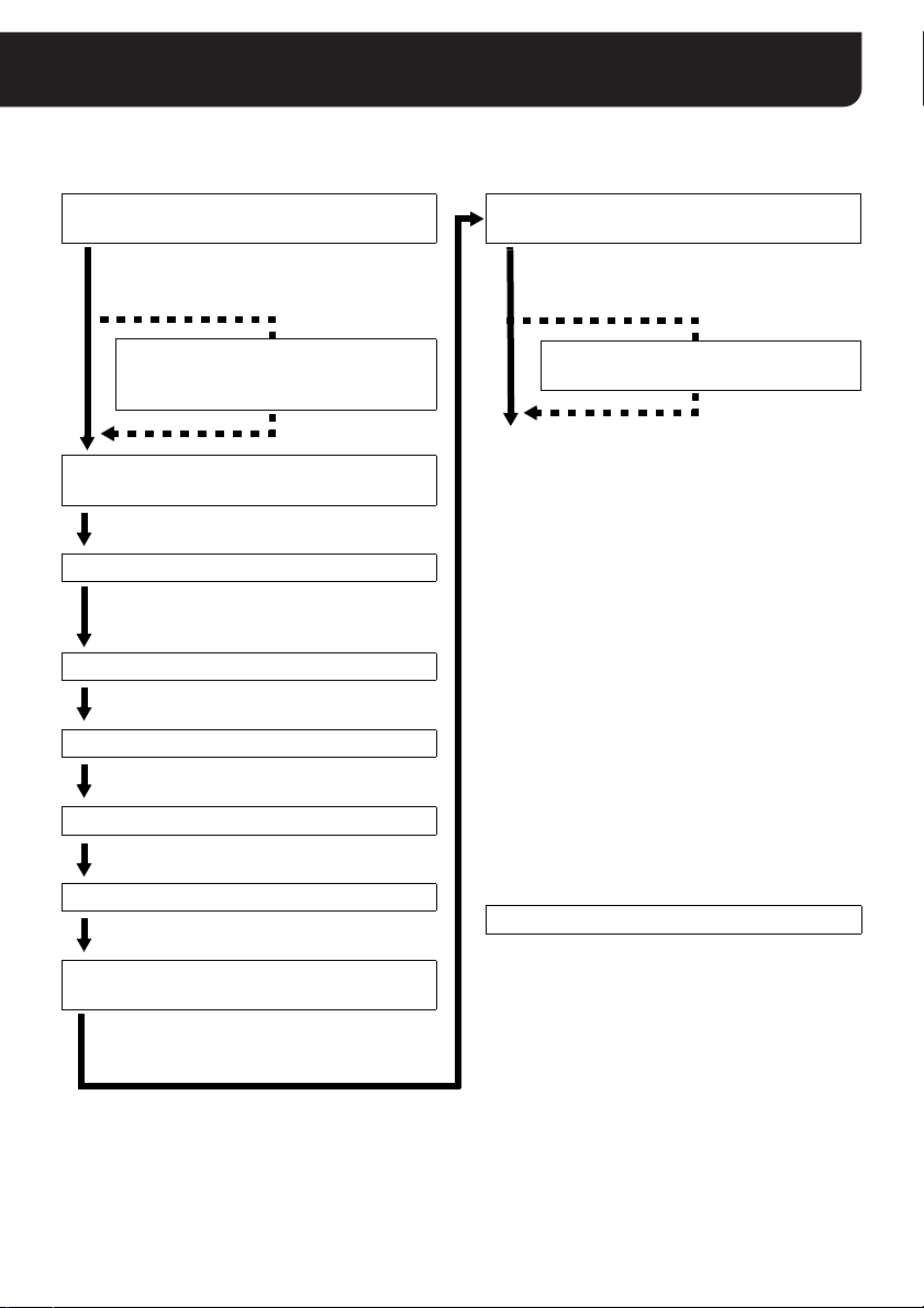
Software Setup Procedure
Perform the following procedures before using the VA-SW3050LITE software. For detailed instructions
on individual procedures, refer to the respective pages shown below.
1 Install the option board (VA-50LAN) on the camera(s)
Refer to the separate “INSTALLATION MANUAL” for how to install the option board on the
camera(s) and make connection using LAN cables.
Configure the TCP/IP settings on PC
To change the IP address for a camera, you must first change the subnet mask and
default gateway values (for the IP address) on the PC, according to the camera. Note that
you must use the same subnet mask and the default gateway values as those for the
camera.
2 Install the VA-SW3050LITE software
3 Start the VA-SW3050LITE software and perform the login
procedure
When you log in to the VA-SW3050LITE for the first time, the [Camera
Setting] screen appears.
4 Register the camera(s) with the software
Register the camera(s) to access, and configure the camera settings such as
IP address and camera title. After registering the camera(s), the live video is
displayed on the main screen.
5 View the live video
You can customize how the video is displayed using the controls on the main
screen.
6 Register users accessing the camera
Register users who log in to the VA-SW3050LITE to access the camera(s).
Page 4
Page 5
Page 7
Page 10
Page 17
English 3
Page 5
Installing the VA-SW3050LITE Software
Install the VA-SW3050LITE software on your PC. Start the installation program, and use the interactive
dialog boxes to advance the installation.
Double-click “Setup.exe” on the supplied
CD-ROM
The installer starts up.
1 Installation of the Microsoft
.NET Framework 1.1
(approximately 2 minutes)
2 [Welcome to the VA-SW3050 Setup
Wizard] dialog
Click [Next].
3 [License Agreement] dialog
Select the “I accept the agreement”
option and click [Next].
4 [Select Destination Location] dialog
Click [Next].
5 [Select Start Menu Folder] dialog
Click [Next].
6 [Ready to Install] dialog
Click [Install].
7 [Installing] dialog
After the installation is completed,
close the dialog
The shortcut icon for the
VA-SW3050LITE appears on the
desktop.
9 Installation of the Microsoft
.NET Framework Service Pack 1
MEMO:
• When you use the non-Japanese version of
Windows, English is used for the display
language during installation.
• Microsoft .NET Framework 1.1 and Service
Pack 1 are required to use the
VA-SW3050LITE software. If these
applications are not installed on your PC, the
install confirmation dialog appears, and the
files are installed automatically (steps 1,
9).
• If you want to change the install destination
folder, click [Browse] to select the desired
folder (step 4).
• If you want to change the Start menu folder,
type the new folder name into the box, or
select the desired folder from the existing
folder list (step 5).
• Restarting the system may be required after
completing the installation. When restarting
the system is required, follow the instruction
displayed on the screen.
To Uninstall the VA-SW3050LITE Software
8 [Completing the VA-SW3050 Setup
Wizard] dialog
Click [Finish].
To uninstall the VA-SW3050LITE software, open
the [Add or Remove Programs] window from the
Control Panel, and select “Network Recorder” to
begin the uninstall procedure.
4 English
Page 6
Starting and Logging in to the VA-SW3050LITE Software
1
3
2
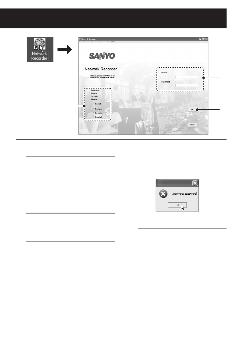
Double-click the shortcut icon on the
1
desktop.
The VA-SW3050LITE starts and the login
screen appears.
MEMO:
The VA-SW3050LITE icon appears in the
task tray at the right bottom corner of the
screen.
Click the appropriate radio button to
2
select the display language.
Available display languages:
English, French, German, and Spanish
Enter the user ID and password.
3
When you log in to the software for the first
time, use the factory setting values below.
USER ID : admin
PASSWORD : admin
Note:
If an invalid user ID or password is entered
three consecutive times, the dialog
displaying the authorization error message
appears. Clicking [OK] closes the login
screen automatically.
Click [OK].
4
• When you start the software for the
first time or no cameras are
registered:
The [Camera Setting] screen appears.
Be sure to register the camera before
starting to use VA-SW3050LITE.
(Refer to “Registering the Cameras
with the Software” on page 7)
• When cameras are registered:
The live video is displayed on the main
screen.
(Refer to “Viewing the Live Video” on
page 10)
4
English 5
Page 7
The following operations are common to each
screen following login.
■ Logging off
Click [Log Off] in the [File] menu.
The login screen is returned to.
■ Closing the screen
Click the button in the top right corner of
the screen.
Alternatively, click [Close] in the [File] menu (the
[Close] button on the login screen).
This operation closes the screen and stores the
software in the task tray icon.
Since this is continually activated as permanent
software, the software remains operating and
functional.
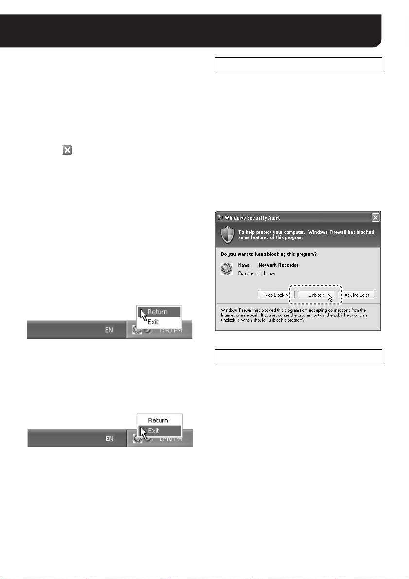
■ Opening the screen
Right-click the icon in the task tray to display
the context menu, and click [Return].
Alternatively, double-click the task tray icon.
The screen appears again.
Disabling the Firewall Protection
When Windows XP Firewall or some other
firewall program is active on your computer, the
computer is blocked from communicating with
the cameras and thus the system fails to operate
correctly. This means that you must disable the
firewall protection before you begin using the
VA-SW3050LITE software.
MEMO:
Note that, if you are using Windows XP SP2, its
firewall protection is enabled by default. When
the VA-SW3050LITE searches for cameras after
startup, the dialog confirming the firewall setting
appears. In this dialog, click [Unblock] to allow
the connection to the camera.
■ Exiting from the software
Right-click the icon in the task tray to display
the context menu, and click [Exit].
This exits from the software, and the task tray
icon disappears.
Concurrent Access via Web Browser
The camera can also be accessed concurrently
by multiple admin users via Web browsers.
However, when the user who uses the software
performs one of the following actions, other
Web-based concurrent admin users will be
disconnected:
• Camera registration
• Clock settings
6 English
Page 8
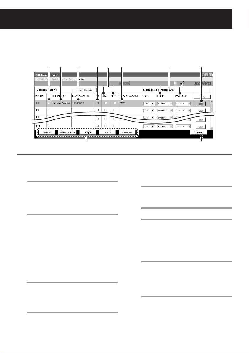
Registering the Cameras with the Software
9
In order to view the live video after logging in, it is necessary to register the connected camera(s) with
the VA-SW3050LITE.
When starting for the first time, or in other cases where the camera is unregistered, the [Camera
Setting] screen appears automatically.
186 3 4 7
(see page 9)
● When registering additional cameras or changing settings, select [Options] and then [Camera
Setting] from the menu bar.
Enter the IP address (or URL) for the camera.
1
If many cameras are connected or the
address is overlapping with another camera,
Using the Camera Search
refer to "
function
Setting communication conditions.
2
When you use the proxy server or SSL
encryption to connect to the camera, select
the appropriate check box respectively.
Note:
Enter the port number set in the camera.
3
The default value depends on the [SSL] setting.
Enter the password.
4
Enter the password for
setting value: guest) configured on the camera.
” on page 8.
• To use proxy server, complete the proxy
settings under the [Options] menu
(refer to “Configuring Other Options”
on page 23).
• Configure the SSL according to the
camera settings.
•SSL (OFF) : 80
• SSL (ON) : 443
guest
user (Factory
25
Set the picture quality and resolution of
5
live images.
In order to make the settings valid,
6
select the check box corresponding to
the camera.
Click [SET].
7
This completes the setting procedure and
the configuration is transferred to the
camera.
When you register multiple cameras, repeat
steps 1 to 7.
Specify the camera title.
8
Set while viewing image(s) for the
registered camera(s).
For details, refer to “Specifying the
camera title” on page 9.
Click [Close].
9
The [Camera Setting] screen closes, and
the main screen opens with the live video
from the camera registered.
English 7
Page 9
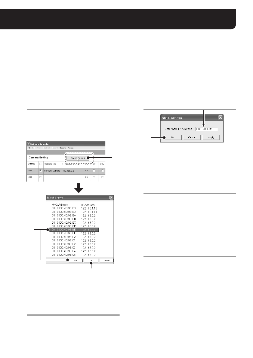
■ Using the Camera Search function
This function automatically searches all cameras connected to the network.
• All of the IP addresses for the detected cameras are listed on the [Camera Setting] screen.
• When there are overlapping IP addresses, you can specify the new IP address on the [Camera
Setting] screen.
MEMO:
At the time of factory shipment, the IP address for every camera is set to “192.168.0.2”. When you
connect multiple cameras with the factory setting, use the Camera Search function to configure the
unique IP address to the cameras.
Click [Search Camera].
1
The MAC and IP addresses for the cameras
detected are listed in the [Search Camera]
dialog. The addresses are displayed in
ascending order for the MAC address.
2
5
If there are any overlapping IP
2
addresses, in the [Search Camera]
dialog, select the camera(s) for which
the IP address needs to be changed and
click [Edit].
The [Edit IP Address] dialog appears.
1
Enter new IP address.
3
4
To change the IP address for a camera, you
must first change the subnet mask and
default gateway values (for the IP address)
on the PC, according to the camera. Note
that you must use the same subnet mask
and the default gateway values as those for
the camera.
Click [OK].
4
The new IP address is transferred to the
camera(s).
The [Edit IP Address] dialog closes, and the
IP address in the [Search Camera] dialog is
also updated.
Use the same procedure (steps 2 to 4) until
there are no overlapping addresses
remaining.
Click [OK] in the [Search Camera] dialog.
5
All the IP addresses displayed in the
[Search Camera] dialog are automatically
reflected in the [Camera Setting] screen.
Note:
If there are any overlapping IP addresses,
the “Duplication Error” message is
displayed. When this error occurs, configure
the IP address again.
8 English
Page 10

Registering the Cameras with the Software
■ Specifying the camera title
Name cameras according to their installed locations, etc. for easy tracking on screen.
1 2
1
Select the camera for which you want to
1
specify the title by clicking the
corresponding row.
The color of the row you selected changes.
Click [View Camera (4)].
2
The still image from the camera(s) you
selected is displayed in the dialog.
A message appears when an error occurs.
A [Reload] button
Updates the still image in the dialog.
B [Close] button
Closes the dialog.
Enter the camera title.
3
The title can be up to 16 alphanumeric
characters.
In order to make the settings valid,
4
select the check box corresponding to
the camera.
Click [SET].
5
This completes the setting procedure and
the camera title is transferred to the
camera(s).
34
AB
5
Other Buttons in the [Camera Setting]
Screen
1
Selecting the check box in the title row
selects all the check boxes corresponding to
the cameras listed on the [Camera Setting]
screen.
2 [Set All] button
Executes the [SET] command for all cameras.
3 4 5 6 7
3 [Reload] button
Reloads the setting information (Camera
Title, Quality, Resolution) to display.
4 [View Camera] button
Displays the still image for the selected
camera(s).
5 [Copy] button
Copies the setting for the selected camera(s)
and retains it in memory.
6 [Paste] button
Overrides the settings for a specified camera
with the copied contents.
7 [Paste All] button
Overrides the settings for all cameras with the
copied contents.
English 9
Page 11

Viewing the Live Video
After registering the camera(s), the live video is displayed on the main screen.
The main screen appears immediately after login when a camera has already been registered.
1
2
3
1 Menu bar (see page 11)
You can access various commands for the
VA-SW3050LITE from the menu bar.
Clicking the menu on the menu bar displays
the pull-down menu. Select the desired
command from the pull-down menu to
execute.
2 Tool bar (see page 13)
The tool bar contains the commands and
information display buttons that are frequently
used.
3 Camera title
The camera title that was set on the [Camera
Setting] screen is displayed.
4 Current date and time
Date and time are displayed according to the
Windows setting.
5 Video display area
Displays the live video.
You can use the button on the tool bar to
select the number of cameras to be displayed
(single screen, 4-part split screen and 16-par t
split screen) (see page 13 2).
6
4
5
6 Close button
Clicking the button closes the screen and
stores the software in the task tray icon
(refer to “Closing the screen” on page 6).
MEMO:
• Clicking the video displays the red frame
around it showing that the camera is
selected.
You need to select a camera before using the
camera controller (see page 15).
Clicking the video again cancels the selection
and the red frame disappears.
• In the following cases, only the message is
displayed with no video.
When image signals are interrupted for
approximately 30 seconds or more:
Communication Error
When no camera is registered:
SANYO
10 English
Page 12

Viewing the Live Video
■ Menu bar functions and operating privileges
• Certain features such as recording and playing the video are not available for the VA-SW3050LITE.
Those features (shaded in the table below) are grayed out and cannot be selected. If you need these
features, use the VA-SW3050 software, which is optionally available.
• The necessary privilege for executing individual operation is shown enclosed with the parentheses in
the Sub-menu column of the table below (ex. “Live View, Camera Control and Menu Setup”).
Configure user privileges on the [Edit Authentication] screen accessible from the [User Registration]
screen (see page 20).
1 2 3 4 5 6 7
Menu Sub-menu Description Refer to
1 File
2 Edit Search Image Searches images. –
3 View
4 Playback Plays the recorded video. –
5 Record Records live videos from all
Backup Backs up recorded data. –
◆ Print (Live View) Prints the live video. Page 13 - 7
Log Off
Close
◆ Full Screen (Live View)
◆ 4 x 4 (Live View)
◆ 1 x 1 (Live View)
◆ Camera
Controller
(Camera Control)
Play/Record
Logs off the software and
displays the login screen.
Closes the screen and stores
the software in the task tray
icon.
Displays the video in full
screen mode.
Displays videos in the 16-part
split screen.
Displays videos in the 4-part
split screen.
Displays video from a single
camera.
Displays the camera controller.
Displays the recording and
playback controller.
cameras simultaneously.
Page 6
Page 6
Page 13 - 1
Page 13 - 2◆ 2 x 2 (Live View)
Page 15
–
–
English 11
Page 13

Menu Sub-menu Description Refer to
6 Options
7 Ve rsion Web Page Displays Sanyo’s homepage. –
Camera Setting (Menu Setup)
Camera Layout Setting
Timer Setting Sets the timer record. –
Alarm Setting Sets the alarm record. –
Delete Data Deletes recorded data. –
Others
About
(Menu Setup)
Data Storage Stores recorded data. –
Proxy (Menu Setup) Sets the proxy server. Page 23
Clock (Menu Setup) Automatically adjusts the time. Page 23
User Registration
(Menu Setup)
Start Up
(Menu Setup)
Popup
Buzzer (Menu Setup) Sets the alarm buzzer. Page 24
Display (Menu Setup) Sets display information. Page 25
Registering the cameras with
the software.
Changes the layout of split
screen images.
Registers the user.
Automatically activates this
software.
Automatically displays the
alarm image.
Displays the version
information of the
VA-SW3050LITE.
Page 21
Page 17
Page 24
Page 7
–
–
MEMO:
The menu item with the ◆ mark can be operated using the tool bar buttons (see page 13).
12 English
Page 14

Viewing the Live Video
■ Tool bar functions
In the VA-SW3050LITE, the buttons used for record and playback operations (5, 6, 9) are grayed out
and cannot be operated.
If you need these features, use the VA-SW3050 software, which is optionally available.
1 2 3 4 5 6 F G7 8 9
1 Screen mode selection button
When selecting the full screen mode, the live
video is maximized across the display without
the title and menu bars displayed.
Full screen
Normal screen
2 Split screen mode selection button
The three modes are available for split screen
display.
4-part split screen mode
16-part split screen mode
Single screen mode
MEMO:
In 4-part or 16-part split screen mode,
double-clicking a specific video will display
the video in single screen mode.
3 Auto screen change button
Use this button to display all the pages
sequentially at specified intervals in the order
of the page number.
Enables or disables the auto
screen change function.
Sets the page switching
intervals as 1, 2 or 3 seconds.
MEMO:
The total number of pages depends on the
number of the cameras and the split screen
mode.
4 Screen change buttons
Switches the displayed page forward or
backward.
Goes back to the page before.
Goes to the next page.
The currently displayed page and
total number of pages
5 [Live All] button
Not available for the VA-SW3050LITE.
6 [Alarm] button
Not available for the VA-SW3050LITE.
7 Print button
Prints the image at the moment when you
click the live video.
Click this button to open the [Print]
dialog and configure the printing
preferences.
8 Button for displaying the camera
controller (see page 15)
Displays the camera controller to operate the
camera remotely from PC.
Displays the camera controller.
Note:
Cannot be operated when no camera is
selected.
English 13
Page 15

9 Button for displaying the recording and
playback controller
Not available for the VA-SW3050LITE.
F Indicator for available hard disk space
Not available for the VA-SW3050LITE.
G Lock button
This button can be used to lock the buttons
and controls for avoiding operation mistakes.
All screen operations are locked.
Releases the lock function.
Adjusting the Camera Orientation
If the camera has a panning-tilting function, in
the single screen mode, clicking the video image
changes the camera orientation so that the point
where you click is located at the center of the
image.
AChanging the camera orientation
Click on the video.
BChanging the camera orientation and
zooming-in
Double-click on the video.
CChanging the camera orientation and
zooming-out
Pressing down and holding the [Shift] key,
double-click on the video.
14 English
Page 16

Operating the Cameras
You can operate the camera remotely from your PC.
Click on the video from the camera you
1
want to operate.
The red frame appears on the selected
video.
Click in the tool bar.
2
Displays the camera controller.
2
3
4
5
1
Camera Controller Functions
If the camera is not equipped with panning-tilting
functions, certain buttons do not work (only the
shaded buttons are usable).
1 Close button
Closes the camera controller.
2 Control buttons
Changes the camera orientation
horizontally and vertically.
Changes the camera orientation
diagonally.
Scans the monitored area end to
end vertically or horizontally, and
stops at the current camera
position.
Starts or stops the sequence,
auto-panning or tour action mode,
respectively.
• The tour action mode is not
available for some models.
Displays the configuration menu
for the camera.
3 Preset position buttons
Applies the registered configuration
for camera orientation, zoom status
and focusing position.
• Select the number for registered
configuration from the pull down
menu and click the [GO] button.
Registers the current camera
orientation along with the zoom and
focus positions as the preset
configuration.
• Select the number to be used for
preset configuration from the pull
down menu and click the
[Memory] button.
English 15
Page 17

4 The shooting function buttons
Zooms in or out.
Adjusts the focus.
Performs automatic focus
adjustment.
Adjusts the iris level.
5 AUX
Used for extended settings.
Select an appropriate AUX
output from the pulldown menu
and then select the setting
between ON and OFF.
■ Changing the configuration stored on
the camera
You can change the shooting preferences stored
on the camera using the control buttons (2).
Displays the configuration menu for
the camera.
·SYNC
BLC
IRIS
WHITE BALANCE
AGC GAIN
GAMMA
SHUTTER
APERTURE
DAY/NIGHT
OPTION
PRESET
MENU
The configuration menu
example
Moves the cursor up/down in the
configuration menu.
Moves the cursor to the left/right in
the configuration menu or changes
the setting value.
Switches to the next screen or
confirms the setting value specified.
Note:
• “Camera Menu Setup” operating privilege is
required.
• The menus displayed depend on the camera
model. For details, refer to the instruction
manual supplied with the camera.
INT
OFF
SET y
ATW
NORM
0.45
60
HIGH
AUTO y
SET y
OFF
END
16 English
Page 18

Registering Users Accessing the Camera
You can register up to ten users (including “admin” user) to log in to the VA-SW3050LITE.
1
A
2
3
4
B
■ User registration
● In the menu bar, click [Options] and select [Others]. Then select [User Registration].
The [User Registration] screen appears.
Enter the user ID.
1
The user ID can be up to 16 alphanumeric
characters. The user ID is case sensitive.
Enter the password.
2
The password can be from 4 to 16
alphanumeric characters. The password is
case sensitive.
Enter the same password again for
3
confirmation.
Click [Add].
4
The new user is added to the [User ID] list
(A).
5
When you register multiple users, repeat
steps 1 to 4.
MEMO:
To configure the operating privileges for
individual users, select the user in the [User ID]
list (A) and click [Edit] (B).
The [Edit Authentication] screen appears (see
page 20).
Click [OK].
5
Click the [OK] button to complete the
registration and close the [User
Registration] screen.
MEMO:
The notations which can be used for user ID and
password are colon (:), period (.), slash (/) and
asterisk (*).
English 17
Page 19

A
2
3
4
■ Changing the user password
Double-click the user ID for which you
1
want to change the password in the
[User ID] list.
The user ID is highlighted in the [User ID]
list and is displayed in the [User ID] box
(A).
Enter the new password.
2
Enter the same password again for
3
confirmation.
Click [Change].
4
The [Change Password] dialog appears.
1
5
6
Enter the current password.
5
Click [OK].
6
Complete the password change.
18 English
Page 20

Registering Users Accessing the Camera
A
2
■ Deleting the registered user
Click the user you want to delete from
1
the [User ID] list.
The user ID is highlighted in the [User ID]
list.
MEMO:
Even when another user ID is displayed in
the [User ID] box (A), the user selected in
the [User ID] list is targeted for deletion.
1
Click [Delete].
2
The dialog confirming deletion of the user
ID appears.
3
Click [OK].
3
The user ID is deleted from the [User ID] list
(1).
Note:
The user “admin” cannot be deleted. Only the
password can be changed.
English 19
Page 21

E D C
■ Setting the user privileges for operating the camera
You can configure the user privileges for operating individual cameras.
Select the user ID for which you want to configure the privileges in the [User Id] list and click [Edit]. The
[Edit Authentication] screen appears. The [Edit Authentication] screen lists all of the registered cameras.
1 2 3 4 5
A
B
6
When granting the operating privilege, select the
corresponding check box under the operation
item, click [Apply] and then click [OK].
MEMO:
In the default settings, check boxes 1 - 5 are
all selected.
For the detailed operating privileges, see page
11.
1 Live View
For monitoring the live video.
2 Playback
For playing the recorded video.
(Not available for the VA-SW3050LITE.)
3 Record
For recording the live video.
(Not available for the VA-SW3050LITE.)
4 Camera Control
For operating the camera remotely.
5 Camera Menu Setup
For configuring the camera settings.
6 Menu Setup
For configuring settings for the [Options]
menu.
(This privilege is configured per user basis.)
Operation Buttons
A [Select All] button
Selects the check boxes for all cameras in the
column corresponding to the button.
B [Clear All] button
Deselects the check boxes for all cameras in
the column corresponding to the button.
C [Apply] button
Saves the settings.
D [Cancel] button
Cancels the settings.
E [OK] button
Completes setting and closes the screen.
Note:
In the case of the user “admin”, all administrative
user operating privileges are set as default. The
operating privileges cannot be changed.
20 English
Page 22

Split Screen Layout
5467
Up to 128 camera images can be viewed on the layout screen.
The image layout can be customized according to your preferences.
2
1
● Select [Camera Layout Setting] from [Options] in the menu bar.
The camera image layout screen appears.
1 Layout pattern
8 patterns (pages 1 - 8) of 16-part split
screens are displayed. Each layout pattern
shows the camera numbers and enables the
display positions of camera images to be
confirmed.
In the default settings, camera numbers are
displayed in their registered order from 001 to
128.
• The color of the camera number will
change depending on the camera’s
registration status.
White: the camera has been registered.
Gray: the camera has not been
registered yet.
• Clicking the camera number highlights the
selected camera on the camera list (3),
enabling the camera title to be confirmed.
2 [Test] button
Clicking the button switches to the [Check
Camera Layout] screen, enabling actual
images displayed on each page to be
confirmed. Click [Return] to return to the
previous screen.
3 Camera list
The camera registered with the
VA-SW3050LITE is listed with its title.
Clicking the camera displays the number of
the selected camera in red on the layout
screen, enabling the image layout to be
confirmed.
4 Quad TYPE
Selects the display pattern in the 4-part split
screen.
5 [Default] button
Resets the display pattern to the initial
setting, which displays the videos in the order
of the camera number.
6 [Set] button
Completes setting and closes the screen.
7 [Cancel] button
Cancels the settings.
3
English 21
Page 23

■ Changing image layout on the 16-part
split screen
Drag the camera number (ex. “001”) on the
1
display pattern diagram with the mouse and
drop it onto the destination (ex. “022”).
The color of the camera number you are
moving changes to red and the [Edit
Camera Layout] dialog appears.
Select the appropriate radio button to choose
2
the movement option and click [OK].
• When you select the option 1, the camera
number you want to move is duplicated and
displayed in the target position.
• When you select the option 2, the camera
number you want to move and the number in
the target position are exchanged.
When 1 is selected When 2 is selected
■ Setting the image layout pattern on
the 4-part split screen
Set the Quad TYPE with the radio button.
1
• Quad TYPE1:
Displays block by block. A block consists
of two rows and two columns.
• Quad TYPE2:
Displays row by row.
Click [Set].
2
Saves the layout settings and the main
screen appears.
1
2
MEMO:
When you select the option 1, the camera number
in the target position is deleted from the pattern
diagram but not from the camera list.
When you want to display the deleted camera
number again, drag the camera number from the
camera list directly and drop it into the target
position.
When you move multiple camera numbers,
repeat steps 1 and 2.
Click [Set].
3
Saves the layout settings and the main
screen appears.
22 English
Page 24

Configuring Other Options
You can configure the following options in relation to using the VA-SW3050LITE.
• Select [Others] from [Options] in the menu bar and then click the menu item you want to bring
up each setting screen.
After completing the settings on each screen, click [Apply] and then click [OK].
■ [Proxy] setting
When you select the [Proxy] check box in the
[Camera Setting] screen, you need to specify
the server information (see page 7).
1
2
1 IP address for the proxy server, and port
number used for connecting to the proxy
server
2 User name and password used for
authorization at the proxy server
• When user name and its password are
required to use the proxy server, select the
[Enable] check box and enter the valid
user name and password in the
appropriate boxes.
• For the valid user name and password,
consult your network administrator.
■ [Clock] setting
The built-in clocks in PCs and cameras can be
adjusted automatically by retrieving the correct
date and time information from the NTP server.
1
2
3
1 NTP Server
When using the automatic clock adjustment
function, enter the domain name or IP
address of the NTP server.
2 Enable
This is a PC setting.
By selecting this check box, the PC internal
clock is automatically adjusted at the
following intervals:
• When setting this function;
• When starting this software; or
• Every 24 hours after startup.
3 Camera
This is a camera setting.
This is only valid when the automatic
adjustment function is set on the PC by
means of the [Enable] setting.
By selecting this check box, the camera
internal clock is automatically adjusted every
time the PC time is adjusted.
English 23
Page 25

■ [Start Up] setting
This option can be used to start the
VA-SW3050LITE automatically at the Windows
startup.
Selecting the check box enables the automatic
startup function.
■ [Buzzer] setting
This option can be used to warn the user by
buzzer.
Selecting the check box enables the function to
activate the warning buzzer on the PC when the
status specified with the following options
occurs.
MEMO:
The buzzer sound is stored as a WAV file.
1
2
3
1 When the alarm is detected. (Alarm)
Clicking the [Alarm] button in the tool bar
stops the buzzer.
(This option is not available for the
VA-SW3050LITE.)
2 When available space on hard disk runs
out. (Disk Full)
Clicking the screen stops the buzzer.
(This option is not available for the
VA-SW3050LITE.)
3 When image signals are interrupted for
approximately 30 seconds or more.
(Communication Error)
Clicking the screen stops the buzzer.
24 English
Page 26

Configuring Other Options
■ [Display] setting
You can choose whether or not to display the
camera title and/or date/time information on
full-screen camera images and print images.
Select the appropriate check box for the item(s)
you want to display.
MEMO:
The camera title and date/time information are
always displayed on the normal screen.
English 25
Page 27

Copyright notice
This instruction manual is copyrighted by SANYO Electric Co., Ltd.
All materials contained in this manual may not be reproduced in any format without the prior permission of the
copyright holder.
• Microsoft, Windows and .NET Framework are registered trademarks or trademarks of Microsoft Corporation in
the United States and other countries.
• An official name for “Windows” used in this manual is Microsoft
note that the word “Windows” refers to both “Microsoft
®
Windows
XP Operating System”.
• Intel and Pentium is a registered trademark or trademark of Intel Corporation and its subsidiaries in the United
States and other countries.
• IBM and IBM PC/AT are trademarks of International Business Machines Corporation.
• Adobe Reader is a trademark of Adobe Systems Incorporated.
• UPnP is a trademark of UPnP Implementers Corporation, which is established by the UPnP Forum SC.
• Java is a trademark of Sun Microsystems, Inc.
All other brands and product names in this manual are the registered trademarks or trademarks of their respective
owners.
®
®
Windows® Operating System. In this manual,
Windows® 2000 Operating System” and “Microsoft®
Page 28

Printed on recycled paper
1AC6P1P3061-L9EBB/WA (0206KP-SY)
SANYO Electric Co., Ltd.
Printed i n Japan
 Loading...