

Page 1

INSTRUCTION MANUAL
Network Recorder
VA-SW3050
Page 2

Table of Contents
Introduction.....................................................2
■ Features...................................................2
■ System Requirements............................2
Installing the VA-SW3050 Software .............. 3
Starting and Logging in to the VA-SW3050
Software........................................................... 5
■ Logging Off .............................................6
■ Closing the Screen................................. 6
■ Opening the Screen................................ 6
■ Exiting From the Software.....................6
Registering the Camera with the Software
■ Using the Camera Search Function...... 8
■ Specifying the Camera Title .................. 9
Basic Operations in the Main Screen ......... 11
■ Menu Bar Functions and Operating
Privileges............................................... 13
■ Tool Bar Functions ............................... 15
Operating the Camera ..................................17
Changing the Camera Configuration
■
Recording Live Video................................... 19
■ About Live Video Recording ...............19
■ Recording Video Manually................... 20
■ Setting the Timer Recording ...............21
■ Setting the Alarm Recording ...............23
........7
... 18
■ Saving Video Found in the Search ..... 31
Checking Alarm Status ................................33
Backing up Recorded Data .......................... 34
User Registration.......................................... 35
■ Registering a New User ....................... 35
■ Changing the User Password.............. 36
■ Deleting a Registered User.................. 37
■ Setting the User Privileges for
Operating the Camera.......................... 38
Split Screen Layout...................................... 39
■ Changing Video Layout on the 16-part
Split Screen........................................... 40
Setting the Video Layout Pattern on the
■
4-part Split Screen................................ 40
Configuring the Options for Storing Videos
on HDD...........................................................41
Deleting Recorded Data............................... 42
Configuring Other Options.......................... 43
■ [Proxy] Setting ...................................... 43
■ [Clock] Setting ......................................43
■ [Start Up] Setting.................................. 44
■ [Popup] Setting.....................................44
■ [Buzzer] Setting .................................... 44
■ [Display] Setting ................................... 44
Playing Recorded Video............................... 25
■ Playback Operations Using the
Recording and Playback Controller.... 26
Printing and Saving Video Images.............. 27
■ Printing Video Images.......................... 27
■ Saving Video Images............................ 27
Video Search.................................................28
■ Search Procedure ................................. 29
■ Zooming in on Search Results ............ 30
■ Playing Video from Search Results .... 30
English 1
Appendix ....................................................... 45
■ Reference Table for Alarm Recording
Time .......................................................45
■ Setting Preference Chart ..................... 46
Page 3

Introduction
Network Recorder is an application software for use with Sanyo’s CCD cameras via network connection.
Installing the Network Recorder on your PC and connecting the PC to a CCD camera(s) through the
option board (VA-50LAN) enable you to operate the camera(s) remotely on the PC display.
■ Features
• Views live video from up to 128 cameras
• Switches screen display between single screen, 4-part split screen or 16-part split screen
• Records and plays live video
• Records live video automatically with timer or alarm recording functions
• Searches the recorded videos by specifying their recorded date and time
• Prints and saves the video images
• Operates cameras remotely and configures the settings stored on the camera
• Accesses cameras simultaneously from up to 16 PCs, including PCs using Web browser
• Registers up to 10 users per PC and sets operating privileges for each camera
• Provides various functions that support monitoring tasks
■ System Requirements
The system requirements for the VA-SW3050 are as follows:
•PC: IBM PC/AT and compatibles
•OS: Windows 2000 Professional SP4,
Windows XP Home Edition SP2, Windows XP Professional SP2
• CPU/Memory:
When the number of cameras connected is 4 or fewer:
CPU: Pentium 4, 2.0 GHz or higher, Memory: 512 MB or more
When the number of cameras connected is between 5 and 16:
CPU: Pentium 4, 3.0 GHz or higher, Memory: 1 GB or more
MEMO:
When you record live videos from 17 or more cameras simultaneously on a single PC,
recording operation may fail depending on your monitoring system configuration. When the
recording operation fails, add PCs used for recording so that the number of cameras to record
simultaneously per PC becomes 16 or fewer.
• Network interface: 100Base-TX
• Display card:
1024 x 768 pixels or higher, 16 million colors or higher
AGP graphics card supporting hardware overlay
Or PCI Express graphics card (Requires the latest DirectX 9.0c compatible driver.)
• Recommended graphics chip
ATI : RADEON9000 series or higher
nVidia : GeForce4 series or higher
Matrox : MillenniumP series or higher
: Quadro4 series or higher
2 English
Page 4
Installing the VA-SW3050 Software
Start the installation program, and use the interactive dialog boxes to advance the installation.
Set the supplied installation CD-ROM
1
into the drive.
The installation program starts
automatically.
Note:
If the VA-SW3050LITE, which is supplied
with the VA-50LAN option board, already
has been installed on your PC, uninstall the
VA-SW3050LITE before installing the
VA-SW3050.
In the [Welcome to the VA-SW3050 Setup
2
Wizard] dialog, click [Next].
The setup wizard for the VA-SW3050 starts.
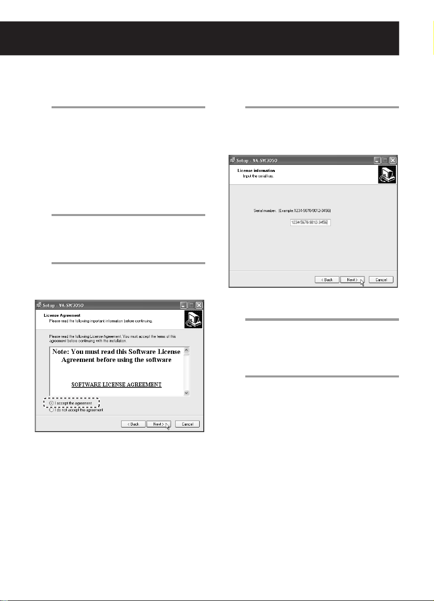
In the [License Agreement] dialog, select
3
the [I accept the agreement] option and
click [Next].
Be sure to read the license agreement
thoroughly before proceeding the
installation.
In the [License information] dialog, enter
4
the serial number and click [Next].
The serial number is shown on the
envelope containing the installation
CD-ROM.
Example: 1234-5678-9012-3456
In the [Select Destination Location]
5
dialog, click [Next].
If you want to change the install destination
folder, click [Browse] to select the desired
folder.
In the [Select Start Menu Folder] dialog,
6
click [Next].
If you want to change the Start menu folder,
type the new folder name into the box, or
select the desired folder from the existing
folder list.
English 3
Page 5

In the [Ready to Install] dialog, click
7
[Install].
The installation starts, and the status of the
installation progress is displayed in the
[Installing] dialog.
After the [Completing the VA-SW3050
8
Setup Wizard] dialog appears, click
[Finish].
This completes the software installation and
closes the dialog. The shortcut icon for the
VA-SW3050 appears on the desktop.
MEMO:
Depending on your system configuration,
restarting the operating system may be
required after installing the VA-SW3050.
When restarting the system is required,
follow the instruction displayed on the
screen.
Installing the .NET Framework
Components
The .NET Framework 1.1 and .NET
Framework Service Pack 1 are required for the
VA-SW3050 to work.
When these components have not been
installed on your PC, the confirmation dialog for
installing them appears automatically before and
after the setup wizard. Clicking [Yes] in the
dialog and following the instructions on the
screen install the .NET Framework components
along with the VA-SW3050.
To Uninstall the VA-SW3050 Software
To uninstall the VA-SW3050 software, open the
[Add or Remove Programs] window from the
Control Panel, and select “Network Recorder” to
begin the uninstall procedure.
MEMO:
Uninstalling the VA-SW3050 does not delete the
configured files and the recorded data stored on
the PC. When you install the VA-SW3050 again,
the newer installation inherits those files and
data.
PC Time Setting
Since the timing of recorded data on this
software is managed according to the PC’s
internal clock, before activating the software,
make sure that the correct time is set in the PC.
If the time setting of the PC is changed while the
software is activated, restart the software.
4 English
Page 6
Starting and Logging in to the VA-SW3050 Software
1
3
2
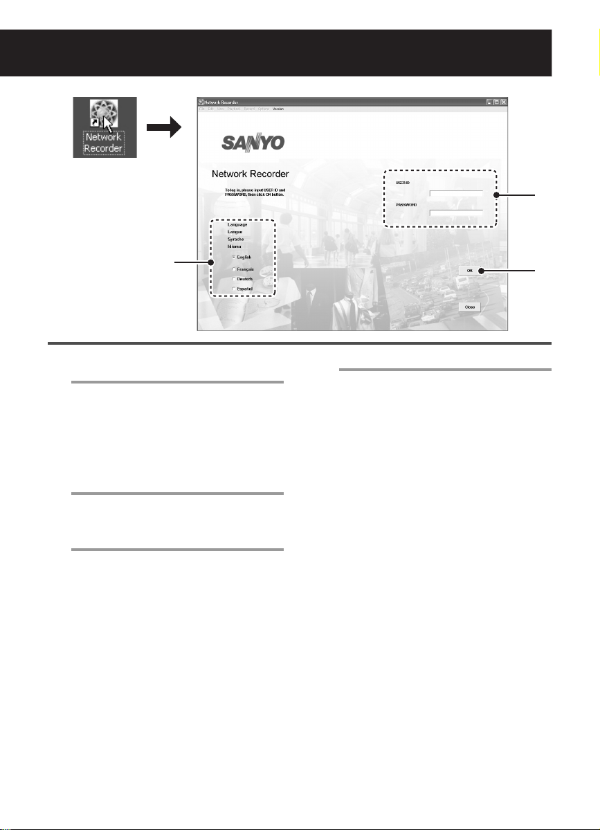
Double-click the shortcut icon on the
1
desktop.
The VA-SW3050 starts and the login screen
appears.
MEMO:
The VA-SW3050 icon appears in the task
tray in the right bottom corner of the screen.
Click the appropriate radio button to
2
select the display language.
Available display languages:
English, French, German, and Spanish
Enter the user ID and password.
3
When you log in to the software for the first
time, use the factory setting values below.
USER ID : admin
PASSWORD : admin
Note:
• For security reasons, be sure to change
the password for the “admin” user from
the factory setting value (see page 36).
• If an invalid user ID or password is
entered three consecutive times, the
dialog displaying the authentication error
message appears. Clicking [OK] closes
the login screen automatically.
Click [OK].
4
• When you start the software for the
first time or no cameras are
registered:
The [Camera Setting] screen appears.
Register the camera(s) with the software
(refer to “Registering the Camera with
the Software” on page 7).
• When cameras are registered:
Live video is displayed in the main
screen (refer to “Basic Operations in the
Main Screen” on page 11).
4
English 5
Page 7
The following operations are common to each
screen following login.
■ Logging Off
Click [Log Off] in the [File] menu.
The login screen is returned to.
■ Closing the Screen
Click the button in the top right corner of
the screen.
Alternatively, click [Close] in the [File] menu (the
[Close] button on the login screen).
This operation closes the screen and stores the
software in the task tray icon.
Since this is continually activated as permanent
software, the software remains operating and
functional.
■ Opening the Screen
Right-click the icon in the task tray to display
the context menu, and click [Return].
Alternatively, double-click the task tray icon.
The screen appears again.
Concurrent Access via Web Browser
The camera can also be accessed concurrently
by multiple admin users via Web browsers.
However, when the user who uses the software
performs one of the following actions, other
Web-based concurrent admin users are
disconnected:
• Camera registration
• Clock settings
• Alarm settings
Disabling the Firewall Protection
When Windows XP Firewall or some other
firewall program is active on your computer, the
computer is blocked from communicating with
the cameras and thus the system fails to operate
correctly. This means that you must disable the
firewall protection before you begin using the
VA-SW3050 software.
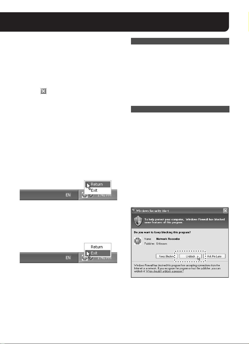
MEMO:
Note that, if you are using Windows XP SP2, its
firewall protection is enabled by default. When
the VA-SW3050 searches for cameras after
startup, the dialog confirming the firewall setting
appears. In this dialog, select [Unblock]. This
operation disables the protection against the
VA-SW3050 and allows the connection to the
camera.
■ Exiting from the Software
Right-click the icon in the task tray to display
the context menu, and click [Exit].
This exits from the software, and the task tray
icon disappears.
6 English
Page 8
Registering the Camera with the Software
3
Registering the cameras with the VA-SW3050 is required for accessing the cameras to display live video.
Set the IP address of registered cameras using “FIX” (manual) mode (see “NETWORK SETTINGS” on
page 12 in the option board instruction manual).
4
2
1
• When no cameras are registered:
After the login procedure, the [Camera Setting] screen automatically appears.
• When you register additional cameras or change the camera settings:
Select [Camera Setting] from [Options] in the menu bar.
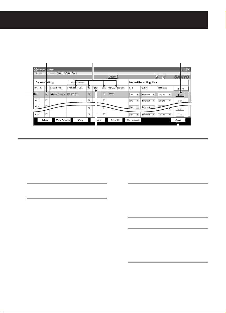
Click the camera number to register in
1
the [CAM No.] column.
The color of the clicked camera row changes.
Enter basic information for the camera.
2
Enter appropriate values according to the
camera settings.
1
IP Address or URL
When changing the address or URL, use the
camera search function (see page 8).
2
Port
The default setting can be “80” or “443”
depending on the [SSL] setting.
3
SSL
When you use the SSL communication for
accessing the camera, select the check box
corresponding to the camera.
4
Camera Password
Enter the password for a
configured on the camera. The default
setting is “guest”.
guest
user
When you use proxy server, select the
3
check box corresponding to the camera.
To use proxy server, complete the proxy
settings under the [Options] menu (see
page 43).
In order to make the settings valid,
4
select the check box corresponding to
the camera.
Click [SET].
5
This operation completes the registration
procedure and starts accessing the camera.
When you register multiple cameras, repeat
steps 1 to 5.
Click [Close].
6
The [Camera Setting] screen closes, and
the main screen opens with the live video
from the camera registered.
5
6
English 7
Page 9
■ Using the Camera Search Function
The camera search function automatically retrieves the IP addresses for all cameras connected to the network.
• This function configures the IP addresses all at once for the cameras found, eliminating the need
to enter IP addresses manually.
• When there are overlapping IP addresses, you can specify a new IP address on the [Camera
Setting] screen.
MEMO:
At the time of factory shipment, the IP address for every camera is set to “192.168.0.2”. When you
connect multiple cameras with the factory setting, use the camera search function to configure the
unique IP address to the cameras.
Note:
• When the confirmation dialog on firewall appears while performing the camera search function,
disable the firewall function to allow the connection to the camera (see page 6).
• The camera search function may detect network devices other than cameras.
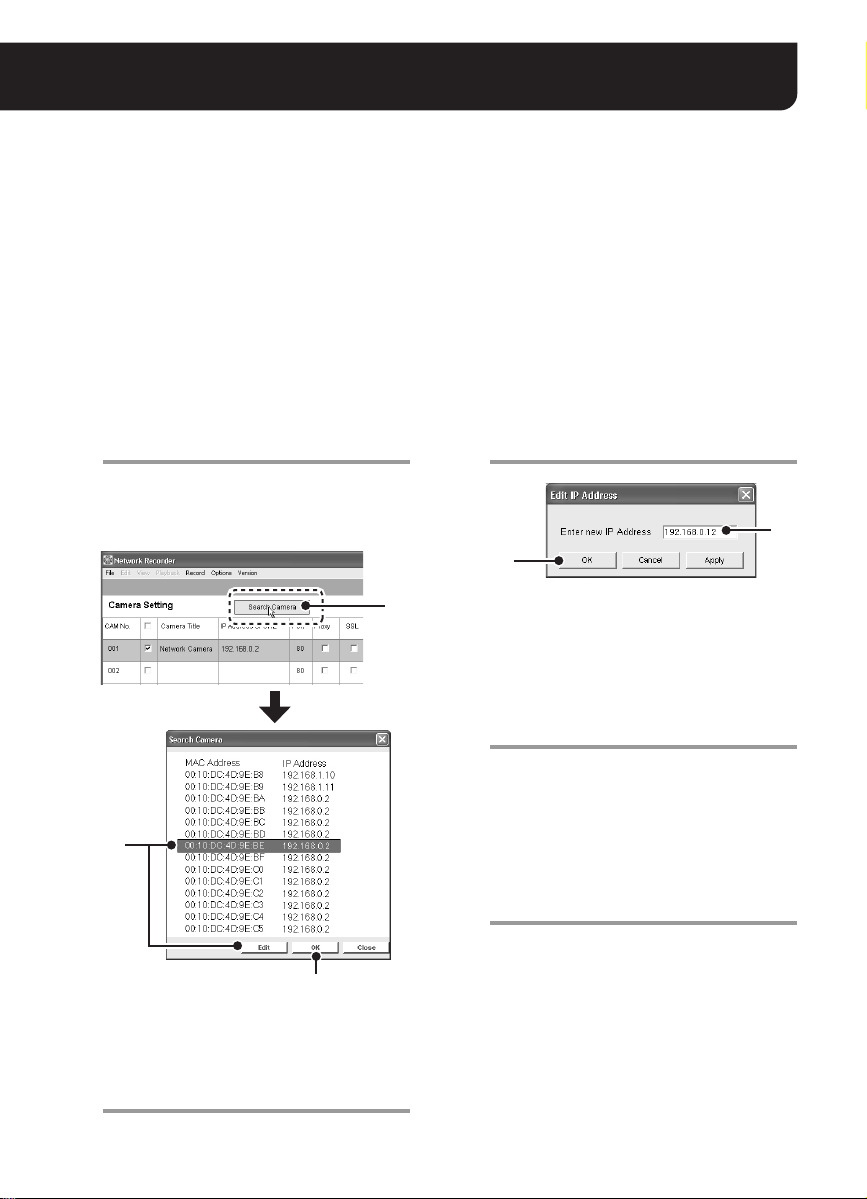
Click [Search Camera].
1
The MAC and IP addresses for the cameras
detected are listed in the [Search Camera]
dialog. The addresses are displayed in the
order of the MAC addresses.
2
5
If there are any overlapping IP
2
addresses, in the [Search Camera]
dialog, select the camera(s) for which
the IP address needs to be changed and
click [Edit].
The [Edit IP Address] dialog appears.
Enter new IP address.
3
4
1
To change the IP address for a camera, you
must first change the subnet mask and
default gateway values (for the IP address)
on the PC, according to the camera. Note
that you must use the same subnet mask
and the default gateway values as those for
the camera.
Click [OK].
4
The new IP address is transferred to the
camera.
The [Edit IP Address] dialog closes, and the
IP address in the [Search Camera] dialog is
also updated.
Use the same procedure (steps 2 to 4) until
there are no overlapping addresses remaining.
Click [OK] in the [Search Camera] dialog.
5
This operation closes the [Search Camera]
dialog, and all the IP addresses displayed in
the [Search Camera] dialog are
automatically reflected in the [Camera
Setting] screen.
Note:
If there are any overlapping IP addresses,
the “IP Address Duplication Error!!”
message is displayed. When this error
occurs, configure the IP address again.
8 English
3
Page 10
Registering the Camera with the Software
3
■ Specifying the Camera Title
For a registered camera, set the camera title while monitoring its live video.
4
1
2
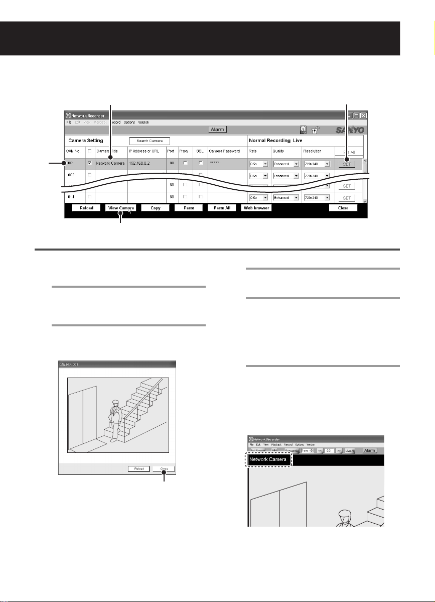
Select the camera for which you want to
1
specify the title by clicking the
corresponding row.
The color of the clicked camera row
changes.
Click [View Camera].
2
The still image from the camera you
selected is displayed in the popup window.
To update the displayed image, click [Reload].
5
Click [Close].
3
This closes the window.
Enter the camera title.
4
It is recommended to set the title according
to the camera location and so on for easier
management on the display.
The title can be up to 16 alphanumeric
characters.
Click [SET].
5
This completes the setting procedure and
the camera title is transferred to the
camera.
MEMO:
When the camera has not been registered
or is not registered appropriately, a
communication error occurs and the image
is not displayed.
English 9
The camera title you specified appears in the
main screen or other setting screens.
Page 11
3
1
2A B C
4 5 6 7
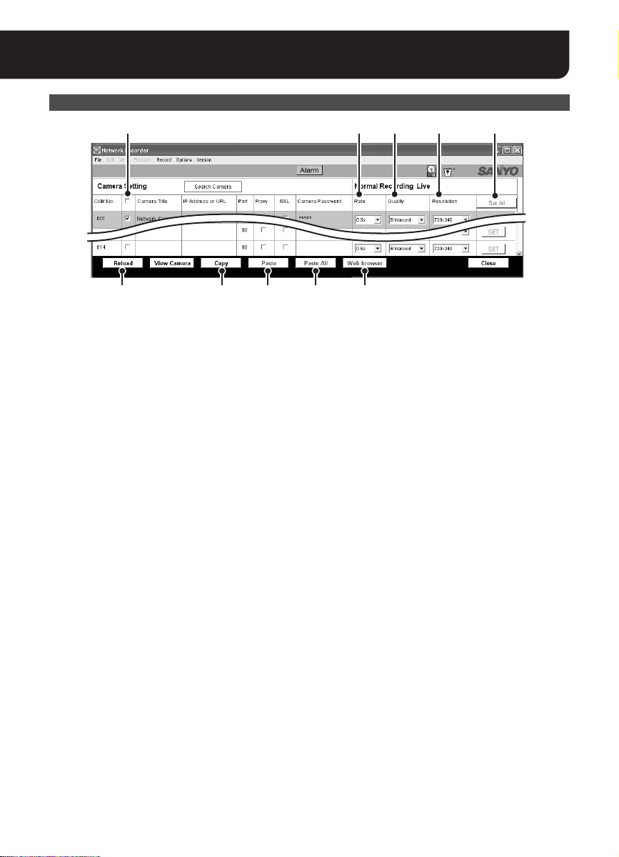
Other Setting Options and Buttons in the [Camera Setting] Screen
<Setting Options>
A Rate:
Specifies the recording interval for normal
recording.
B Quality:
Changes the video quality preferences for live
video and normal recording configured on the
camera.
C Resolution:
Changes the video resolution preferences for
live video and normal recording configured on
the camera.
After specifying the options above, select the
check box corresponding to the camera and
click [SET].
<Operation Buttons>
1 Select all check box
Selecting this check box in the title row
selects all the check boxes corresponding to
the cameras listed on the [Camera Setting]
screen.
2 [Set All] button
Executes the [SET] command for all cameras.
3 [Reload] button
Reloads the setting information (Camera
Title, Quality, Resolution) to display.
Note:
When registering cameras on two or more
PCs
If you don’t want to change the contents set in
the camera, after inputting the IP address and
camera password, load the current setting
information using the [Reload] button.
4 [Copy] button
Copies the settings for the selected camera
and retains them in memory.
5 [Paste] button
Overrides the settings for the selected
camera with the copied contents.
6 [Paste All] button
Overrides the settings for all cameras with the
copied contents.
7 [Web browser] button
Starts the Web browser to automatically
access the selected camera.
Refer to the option board instruction manual
for operations following access.
10 English
Page 12
Basic Operations in the Main Screen
After registering the camera(s), the live video is displayed in the main screen.
The main screen appears immediately after login when a camera has already been registered.
1
2
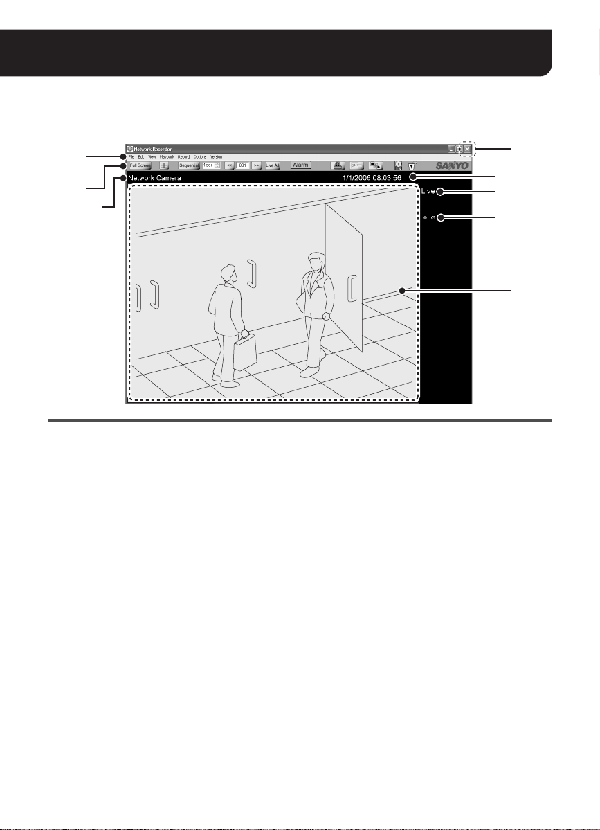
A
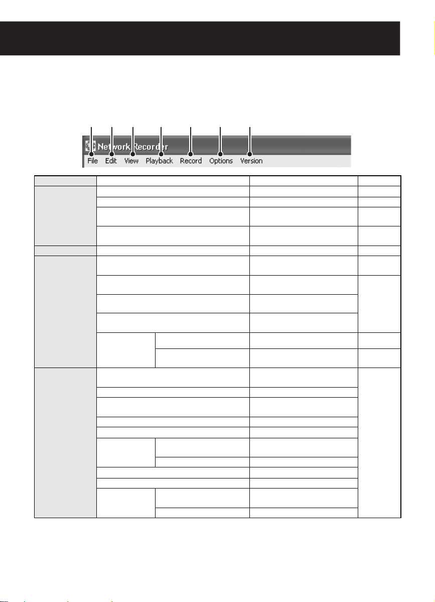
1 Menu bar (see page 13)
You can access various commands for the
VA-SW3050 from the menu bar.
Clicking the menu on the menu bar displays
the pull-down menu. Select the desired
command from the pull-down menu to
execute.
2 Tool bar (see page 15)
The tool bar contains the commands and
information display buttons that are frequently
used.
4
B
C
D
3
3 Video display area
Displays the live video and recorded data.
You can use the button on the tool bar to
select the number of cameras to be displayed
(single screen, 4-part split screen or 16-part
split screen) (see page 15).
MEMO:
In the following cases, only the following
message is displayed respectively with no
video.
When image signals are interrupted for
approximately 30 seconds or more:
Communication Error
When no camera is registered:
SANYO
When there is no video to display during
playback operation:
No Data
4 Close button
Clicking the button closes the screen and the
software is stored in the task tray icon (see
page 6).
11 English
Page 13
Information Displayed in the Monitor Section
The following information is displayed in the
video display area.
A Camera title
The camera title specified in the [Camera
Setting] screen is displayed.
B Date and time information
Live video Current date and time
Playback video
MEMO:
Date and time are displayed according to the
Windows setting.
C Video type
Live video Live
Playback
video
D Recording information
The recording status is displayed using marks
or text.
a(red) During recording
£(white) Timer recording standby
£(red) During timer recording
Alarm (red) During alarm recording
Recorded date and time
Play (Recorded video by
normal recording)
Play Alarm
(Recorded video by alarm
recording)
Still (Still image from
recorded video)
(manual, timer or alarm
recording)
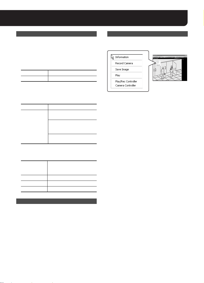
Using the Context Menu
Right-clicking the video displays the context
menu.
The context menu enables you to perform the
following commands without using the controller
or menu bar.
• Information:
Displays the camera information.
• Record Camera/Record Stop Camera:
Starts or stops recording.
• Save Image:
Saves the video image.
• Play/Live:
Starts or stops playing.
• Play/Rec Controller:
Displays the recording and playback
controller.
• Camera Controller:
Displays the camera controller.
Selecting the Camera to Operate
When a video is clicked, a red frame is displayed
around it showing that the camera has been
selected.
In this software, it is necessary to select a
camera in the following cases:
• When displaying the camera controller
• When performing recording, playback or
saving operation
Clicking the video again or clicking another
video deletes the red frame and disables
selection of the camera.
12 English
Page 14
Basic Operations in the Main Screen
■ Menu Bar Functions and Operating Privileges
The VA-SW3050 allows you to configure the user privileges (Live View, Playback, Record, Camera
Control, Camera Menu Setup, Menu Setup) on an individual camera basis. The necessary privileges for
executing individual operation are shown enclosed in parentheses in the sub-menu column of the table
below (see “Setting the User Privileges for Operating the Camera” on page 38).
1 2 3 4 5 6 7
Menu Sub-menu (Privilege) Description Refer to
1 File Backup
◆ Print
(Menu Setup)
(Live View)
Log Off
Close
2 Edit Search Image
3 View
◆ Full Screen
◆ 4 x 4
◆ 2 x 2
◆ 1 x 1
Controller
4 Playback
◆ Live
◆ Playback
◆ Reverse Playback
◆ Playback Speed
◆ Pause
Frame Skip
◆ Fast Forward
◆ Rewind
Alarm Skip
◆ Camera
◆ Play/Rec Controller
◆ Previous
◆ Next
◆ Previous
◆ Next
(Playback)
(Live View)
(Live View)
(Live View)
(Live View)
Controller
(Camera Control )
(Playback)
(Live View)
(Playback)
(Playback)
(Playback)
(Playback)
(Playback)
(Playback)
(Playback)
(Playback)
(Playback)
(Playback)
MEMO: The menu item with the ◆ mark can be operated using the tool bar buttons (see page 15).
Backs up recorded data.
Prints the video image.
Logs off the software and
displays the login screen.
Closes the screen and stores the
software in the task tray icon.
Searches videos.
Displays the video in the full
screen mode.
Displays videos in the 16-part
split screen.
Displays videos in the 4-part
split screen.
Displays video from a single
camera.
Displays the camera controller.
Displays the recording and
playback controller.
Stops the playback and displays
live video.
Starts playback.
Starts playback in reverse
direction.
Changes the playback speed.
Stops playback temporarily.
Plays the video frame-by-frame
in reverse direction.
Plays the video frame-by-frame.
Starts fast-forward playback.
Starts fast-rewind playback.
Skips to the previous alarm
video.
Skips to the next alarm video.
Page 34
Page 27
Page 6
Page 6
Page 28
Page
15 - 1
Page
15 - 2
Page 17
Pages 20, 26
Page 26
English 13
Page 15
Menu Sub-menu (Privilege) Description Refer to
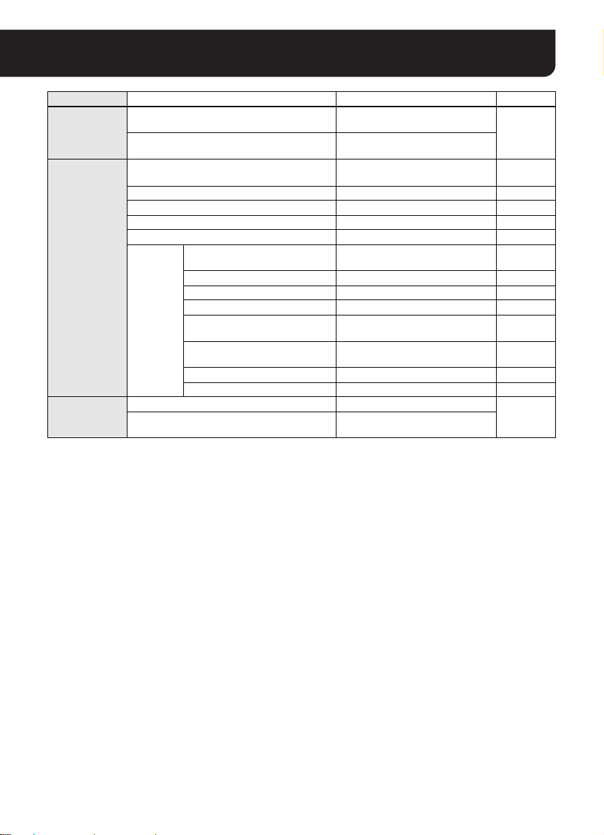
5 Record
Record All Camera
Record Stop All Camera
6 Options
Camera Setting
Camera Layout Setting
Timer Setting
Alarm Setting
Delete Data
Others
7 Version Web Page
About
DATA Storag e
Proxy
Clock
User Registration
Start Up
Popup
Buzzer
Display
(Menu Setup)
(Menu Setup)
(Menu Setup)
(Menu Setup)
(Menu Setup)
(Menu Setup)
(Menu Setup)
(Menu Setup)
(Menu Setup)
(Menu Setup)
(Menu Setup)
(Menu Setup)
(Menu Setup)
Records live videos from all
(Record)
cameras simultaneously.
Stops recording for all cameras
(Record)
simultaneously.
Registers the camera with the
software.
Changes the split screen layout.
Sets the timer recording.
Sets the alarm recording.
Deletes recorded data.
Configures the options for storing
videos on HDD.
Sets the proxy server.
Automatically adjusts the time.
Registers the user.
Automatically activates this
software.
Automatically displays the alarm
image.
Sets the alarm buzzer.
Sets display information.
Displays Sanyo’s homepage.
Displays the version information of
the VA-SW3050.
Page 20
Page 7
Page 39
Page 21
Page 23
Page 42
Page 41
Page 43
Page 43
Page 35
Page 44
Page 44
Page 44
Page 44
–
14 English
Page 16

Basic Operations in the Main Screen
■ Tool Bar Functions
1 2 3 4 5 6 F G7 8 9
1 Screen mode selection button
When selecting the full screen mode, live
video is maximized across the display without
the title and menu bars.
Full screen
Normal screen
2 Split screen mode selection button
Three modes are available for the screen
display pattern.
Single screen mode
4-part split screen mode
16-part split screen mode
MEMO:
In the 4-part or 16-part split screen mode,
double-clicking a specific video displays the
video in single screen mode.
3 Auto screen change button
Use this button to display all the pages
sequentially at specified intervals in the order
of the page number.
Enables or disables the auto
screen change function.
Sets the page switching
intervals as 1, 2 or 3 seconds.
MEMO:
• The total number of pages depends on the
number of the cameras and the split
screen mode.
• When the auto screen change function is
enabled, no operations can be executed
apart from setting the page switching
interval. To perform any other operations,
disable this function.
4 Screen change buttons
Switches the displayed page forward or
backward manually.
Goes back to the page before.
Goes to the next page.
The currently displayed page and
total number of pages
5 button
Stops the playback for all cameras
simultaneously and displays live video.
6 button (see page 33)
The color of the button indicates the alarm
status.
Clicking the button opens the [Alarm] dialog
for viewing the alarm history and image.
7 Print button (see page 27)
This button allows you to print out the image
from live video or recorded video.
Displays the dialog for printing out
the image.
8 Camera controller display button
(see page 17)
Displays the camera controller to operate the
camera remotely from PC.
Displays the camera controller.
Note:
Cannot be operated when no camera is
selected.
English 15
Page 17

9 Button for displaying the recording and
playback controller (see pages 20, 26)
Displays the recording and playback
controller that can be used to perform
recording or playback operations.
Displays the recording and
playback controller.
F Indicator for available hard disk space
The following icons are used for representing
the available hard disk space.
When the hard disk space is full, the
recording stops.
100% to 10% of the hard disk
space is available.
10% to 5% of the hard disk space
is available.
5% to 0% of the hard disk space is
available.
MEMO:
The icons above do not appear when the
[When HDD is fully recorded] option is set to
“Overwrite” in the [DATA Storage] screen
under the [Options] menu.
G Lock button
This button can be used to lock the buttons
and controls for avoiding operation mistakes.
All screen operations are locked.
Releases the lock function.
Adjusting the Camera Orientation
If the camera has a panning-tilting function, click
the video in the single screen mode for
exploiting the function.
Clicking the video in the single screen mode
changes the camera orientation so that the point
where you click is located at the center of the
image.
AChanging the camera orientation
Click on the video.
BChanging the camera orientation and
zooming-in
Double-click on the video.
CChanging the camera orientation and
zooming-out
Pressing down and holding the [Shift] key,
double-click on the video.
16 English
Page 18

Operating the Camera
The VA-SW3050 allows you to operate the camera remotely from PC using the camera controller on the
screen.
Click on the video from the camera you
1
want to operate.
A red frame appears around the selected
video.
Click in the tool bar.
2
Displays the camera controller.
1
2
3
4
5
Camera Controller Functions
If the camera is not equipped with panning-tilting
functions, certain buttons do not work (only the
shaded buttons are usable).
1 Control buttons
Changes the camera orientation
horizontally and vertically.
Changes the camera orientation
diagonally.
Scans the monitored area end to
end vertically or horizontally, and
stops at the current camera position.
Starts or stops the sequence,
auto-panning or tour action mode,
respectively.
• The tour action mode is not
available for some models.
Displays the configuration menu for
the camera.
2 Preset position buttons
Applies the registered configuration for
camera orientation, zoom status and
focusing position.
• Select the number for registered
configuration from the pull-down
menu and click [GO].
Registers the current camera
orientation along with the zoom and
focus positions as the preset
configuration.
• Select the number to be used for
preset configuration from the
pull-down menu and click
[Memory].
English 17
Page 19

3 Shooting function buttons
Zooms in or out.
Adjusts the focus.
Performs automatic focus
adjustment.
Adjusts the iris level.
4 ON/OFF buttons for extended settings
(AUX)
Select an appropriate number
from the pull-down menu and then
select the setting between ON and
OFF.
5 Close button
Closes the camera controller.
Note:
Depending on the functions or specifications of
the camera, some operations may not work
though the button is displayed.
■ Changing the Camera Configuration
You can change the shooting preferences stored
on the camera using the control buttons (1).
Displays the configuration menu for the
camera.
·SYNC
BLC
IRIS
WHITE BALANCE
AGC GAIN
GAMMA
SHUTTER
APERTURE
DAY/NIGHT
OPTION
PRESET
MENU
The configuration menu
example
Moves the cursor up/down in the
configuration menu.
Moves the cursor to the left/right in the
configuration menu or changes the
setting value.
Switches to the next screen or confirms
the setting value specified.
Note:
• “Camera Menu Setup” operating privilege is
required.
• The menus displayed depend on the camera
model. For details, refer to the instruction
manual supplied with the camera.
INT
OFF
SET y
ATW
NORM
0.45
60
HIGH
AUTO y
SET y
OFF
END
18 English
Page 20

Recording Live Video
■ About Live Video Recording
The VA-SW3050 enables you to record live video from cameras in the following four ways.
Recording
Mode
Normal
recording
Alarm
recording
Recording
Method
Records live video in manual operation.
In manual recording, the following recording
Manual
recording
Timer
recording
The alarm recording starts live video recording automatically, triggered by an input
signal from a device connected to the camera such as door switch or infrared sensor.
Recording on
the PC’s hard
disk drive
directly
Recording on
the camera’s
memory
temporarily
operations are available:
• Recording by specifying the camera to record the live
video
• Recording live videos from all cameras
simultaneously
The timer recording enables you to record live video
automatically by specifying the start and end times.
[Timer Setting]
Use the
recording.
Records the post-alarm video after the alarm signal
for specified duration on the PC’s hard disk drive.
[Alarm Setting]
Use the
recording duration.
Note:
In this recording method, the pre-alarm recording is
not available.
Records both the pre- and post-alarm video before
and after the alarm signal respectively on the
camera’s memory by specifying the recorded video
size. The recorded alarm video is transferred one by
one to the PC and stored on the hard disk drive.
[Alarm Setting]
Use the
alarm video size and the ratio between the pre- and
post-alarm video size in alarm recording.
Pre-alarm
recording
Description
screen to configure the timer
screen to configure the
screen to configure the total
Post-alarm recording
Refer
to
Page
20
Page
21
Page
23
Alarm detected
Alarm recording
When you perform the pre-alarm recording, you can
check the video from the point immediately before the
alarm signal while playing the alarm video.
MEMO:
• The recorded video data is stored on the PC’s hard disk drive. The preferences on storing the
recorded video can be configured in the [DATA Storage] screen (see page 41).
• Set video quality, etc. in normal recording on the [Camera Setting] screen (see page 10).
Note:
• If simultaneously accessing from multiple PCs, alarm recording can only be performed from one.
• Depending on the network environment, PC performance or number of PCs connected, it may not be
possible to record at the designated recording rate.
English 19
Page 21

■ Recording Video Manually
Recording by Specifying the Camera to
Record the Live Video
Click on the video from the camera you
1
want to record.
A red frame appears around the selected
video.
Click in the tool bar.
2
The recording and playback controller
appears.
2 1
Click (1) in the controller.
3
This starts recording and the a(red) mark
appears to the right of the live video.
You can record live video from multiple
cameras by repeating steps 1 and 3 above.
To stop recording:
4
Click the video you want to stop recording.
After confirming the red frame showing that
the video has been selected, click (2)
in the controller.
This stops recording and the a(red) mark
disappears.
MEMO:
• You can perform recording operations while
playing the video.
• You can also use the menu bar or context
menu to display the recording and playback
controller or to start and stop recording.
Recording Live Videos from All Cameras
Simultaneously
Select [Record All Camera] from
1
[Record] in the menu bar.
This starts recording for all cameras and the
a(red) mark appears to the right of each
live video.
To stop recording for all cameras
2
simultaneously:
Select [Record Stop All Camera] from
[Record] in the menu bar.
This stops recording for all cameras and the
a(red) marks disappear.
20 English
Page 22

Recording Live Video
■ Setting the Timer Recording
1
2
● Select [Timer Setting] from [Options] in the menu bar.
The [Timer Setting] screen appears. The timer recording is configured on an individual camera basis.
Click the camera number tab
1
corresponding to the camera for which
you want to configure the timer
recording.
Use the buttons to scroll the tab
display.
Select the day of the week (“SUN” to
2
“SAT”) from the pull-down menu under
the [Day] column.
When you want to record for the same time
everyday, select [DLY].
Specify the start and end times for
3
recording under the [Start] and [Stop]
columns respectively.
To enable the setting, select the “On”
4
radio button under the [Set] column.
3 4
6
When you configure multiple timer recording
settings, use the same procedure (steps 2 to
4) for the other timer setting rows.
You can configure up to 8 timer recording
settings per camera.
Click [Apply].
5
This saves the settings for timer recording.
Click [OK].
6
This completes settings and closes the
[Timer Setting] screen.
MEMO:
• After completing the timer recording
• The timer recording is performed
5
setting, the VA-SW3050 enters the
standby status for timer recording and
the £(white) mark appears to the right of
the video from the camera.
according to the clock on the PC where
the VA-SW3050 is installed.
English 21
Page 23

Setting the Timer Recording Across
Midnight
You can set the timer recording across midnight
by specifying the end time earlier than the start
time.
Example:
The recording starts at 20:00 on Sunday and
ends at 10:00 on the next Monday.
Setting the Timer Recording for 24 Hours
The timer recording is performed for 24 hours by
specifying the same time for both the start and
end times.
Example:
The recording starts at 00:00 on Sunday and
lasts for 24 hours.
Setting the Timer Recording for Longer
than 24 Hours
1 Click [Over 24H].
The two rows from the bottom (the 7th and
8th rows) are changed to the format for
specifying the over 24-hour timer recording.
2 In the upper row, specify the day of the
week and time for the start of recording.
3 In the lower row, specify the day of the
week and time for the end of recording.
Example:
Setting Holidays
By setting national holidays or anniversaries as
holiday, holidays are treated as Sunday and the
timer recording is performed accordingly.
Clicking the [Holiday Setting] tab displays the
screen for holiday setting. Use the pull-down
menu to select the date to treat as holiday.
MEMO:
• Up to 20 days can be set as holiday.
• If you select a day that has already been set
as holiday, the “HOLIDAY DUPLICATION
ERROR!!” message appears.
The timer recording is performed for 30
consecutive hours from 16:00 on Saturday
through 22:00 on the next Sunday.
MEMO:
• Only one setting can be made with the timer
recording for over 24 hours.
• Clicking [Over 24H] again restores the normal
format.
22 English
Page 24

Recording Live Video
■ Setting the Alarm Recording
1
1
32
2
4
3
● Select [Alarm Setting] from [Options] in the menu bar.
The [Alarm Setting] screen appears. The alarm recording is configured on an individual camera
basis.
Click the camera for which you want to configure the alarm recording.
1
The color of the clicked camera row changes.
Select the recording method.
2
You can record the alarm video on the PC’s hard disk drive directly or on the camera’s memory
temporarily. The alarm video on the camera is transferred to the PC later and stored on the hard
disk drive.
When Recording on the PC’s Hard Disk
Drive Directly
This recording method can set long recording
hours and is suitable when giving priority to
the recording time.
In this method, the pre-alarm recording is not
available.
• Alarm area:
Set this option to “PC”.
• Alarm Duration (Post):
Set the recording duration per alarm
recording. During an alarm recording, no
other alarms will be processed.
4 5 6
6
When Recording on the Camera’s
Memory Temporarily
This recording method can set the recording
rate high and is suitable when giving priority to
the recording rate.
In this method, the pre-alarm recording is
available.
• Alarm area:
Specify the amount of the memory on the
camera (“0.5MB” to “Max”) allocated to the
alarm recording (for detailed duration
available in alarm recording, see page 45).
• Alarm Duration (Pre/Post):
Specify the memory usage ratio between preand post-alarm recording.
5
English 23
Page 25

Specify the video options in alarm
3
recording.
• Rate:
Configures the recording rate for the
alarm recording.
The available options depend on the
[Alarm area] and [Resolution] settings.
•Quality:
Can change the alarm video quality
setting in the camera.
• Resolution:
Can change the alarm video resolution
setting in the camera.
In order to make the settings valid,
4
select the check box corresponding to
the camera.
Click [SET].
5
This completes the setting procedure and
the configuration is transferred to the
camera.
When you configure the alarm recording for
multiple cameras, repeat steps 1 to 5.
MEMO:
When the value for the [Alarm Duration] option is
not selected, the alarm recording for the camera
is disabled. Be sure to select the value
according to the message on the dialog.
Click [Close].
6
The [Alarm Setting] screen closes.
Note:
When recording on the camera’s memory
temporarily
• Pre-alarm video may not be recorded under
the following settings. Change one of the
settings according to the contents in the
parentheses.
Alarm area:0.5MB (increase capacity)
Alarm Duration (Pre/Post):
10%90% (raise the ratio)
Quality:Super Fine (lower picture quality)
• During alarm recording, the alarm video
being received from the camera is displayed.
Since there is a time lag before video is
received, the displayed video will differ from
the live video.
Other Buttons in the [Alarm Setting]
Screen
1 Select all check box
Selecting this check box in the title row
selects all the check boxes corresponding to
the cameras listed on the [Alarm Setting]
screen.
2 [Set All] button
Executes the [SET] command for all cameras.
MEMO:
When the value for the [Alarm Duration]
option is not selected, the alarm recording for
the camera is disabled. Be sure to select the
value according to the message on the
dialog.
3 [Reload] button
Reloads the setting information to display.
MEMO:
While the setting information is being
accessed concurrently, [Reload] button can
be used to load and check the current setting
information retained on the camera.
4 [Copy] button
Copies the settings for the selected camera
and retains them in memory.
5 [Paste] button
Overrides the settings for the selected
camera with the copied contents.
6 [Paste All] button
Overrides the settings for all cameras with the
copied contents.
24 English
Page 26

Playing Recorded Video
Click on live video from the camera for
1
which you want to play the recorded
video.
A red frame appears around the selected
video.
Click in the tool bar.
2
The recording and playback controller
appears.
B A C
Click (A) or (B) in the controller.
3
This starts playback (or reverse playback)
and the video type indicator changes from
“Live” to “Play”.
You can play recorded videos from multiple
cameras by repeating steps 1 and 3 above.
Operate the playback using the
4
controller.
Playback operations such as fast-forward
and pause can be made with the buttons on
the controller (see page 26).
MEMO:
You can also perform the playback
operations using the [Playback] menu
commands in the menu bar.
To stop playback:
5
Click the video you want to stop playback.
After confirming the red frame showing that
the video has been selected, click (C)
in the controller. This stops the playback
and the live video is displayed again.
MEMO:
Clicking in the tool bar
simultaneously stops the playback for all the
recorded videos currently played and all the
live videos of the cameras for which the
recorded video is played are displayed
again.
About Playback Basic Operations
• Whether normal or alarm recording, all the
recorded videos are played in chronological
order.
• When you play the recorded video next time,
the playback starts from the point where the
playback stopped last time.
• When you play the recorded video next time
after exiting from the VA-SW3050, the
playback starts from the oldest one.
• When the playback comes to the end of the
recorded videos, the playback pauses and
the still image is displayed.
Clicking (C) in the controller displays the
live video again.
• When the reverse or fast-rewind playback
goes to the beginning of the oldest video, the
normal playback starts. When the
frame-by-frame reverse playback goes to the
beginning of the oldest video, the playback
pauses and the still image is displayed.
• You can perform playback operations while
recording live video.
MEMO:
• You can also use the menu bar or context
menu to display the recording and playback
controller or to start and stop playback.
• You can use the video search function to play
the recorded video that matches the
conditions you specify (see page 28).
English 25
Page 27

■ Playback Operations Using the Recording and Playback Controller
1
2 3 4 5 6 7 8 9 F G
Normal display
A
B
Expanded display with the time scale panel
The Recording and Playback Controller
Displays the beginning of the alarm video
1 :
currently played (If you click the button
when the position near the beginning of
the video is played, this button displays the
beginning of the previous alarm video).
Displays the beginning of the next alarm
2 :
video.
Plays the video frame-by-frame in
3 :
reverse direction during playback pause.
Plays the video frame-by-frame in
4 :
forward direction during playback pause.
Fast-rewinds the video at 120X speed.
5 :
Fast-forwards the video at 120X speed.
6 :
Note:
When you want to fast-forward or fast-rewind the
video, press and hold the button.
Starts playback in reverse direction.
7 :
Stops the playback temporarily and
8 :
displays the still image.
Plays the video.
9 :
F :
MEMO:
• When “0.5S” is selected, video is played back at the
rate of two frames per second. The video is
continuously played back even when there is a break.
•
The playback speed remains the same even when
the playback video (red framed video) is changed.
If you want to change the playback speed, reset it
or click the playback button (
Changes the playback speed
(1/20X to 100X speed, 0.5S).
9).
H
Click this
button to
display the
expanded
controller
C
G :
H :
Clicking (H) displays the time scale panel in
the lower area of the controller.
A Time scale
B Scale
C (Close button)
Stops playing the recorded video and
displays the live video.
Opens the time scale panel.
Time Scale Panel
The center line of the time scale represents
the recorded date and time for the video
currently played.
MEMO:
Dragging the time scale to the left or right
changes the current play point of the
recorded video.
Drag to right Turns back the playing date
Drag to left Advances the playing date
Selects the unit used for the time scale.
MINUTE 60 scales for 60 minutes
HOUR 24 scales for 24 hours
DAY 30 (or 31) scales for 30 (or 31)
Closes the time scale panel.
and time.
and time.
days
26 English
Page 28
Printing and Saving Video Images
The VA-SW3050 allows you to print or save the video image from the live or recorded video displayed
on the screen.
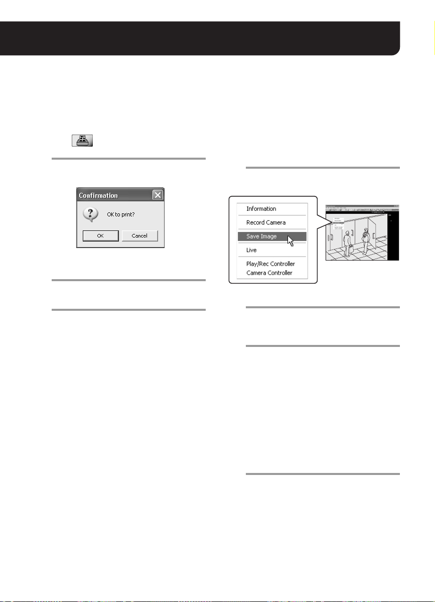
■ Printing Video Images
You can print the video image in the video
display area of the main screen.
Click in the toolbar while the live
1
or recorded video is played.
The video changes to the still image and the
confirmation dialog appears.
When you want to print the image, click
2
[OK].
The [Print] dialog appears.
Confirm the settings and click [OK].
3
The still image is printed out.
After the printing completes, the still image
changes back to the live or recorded video.
MEMO:
The preferences for displaying the camera title
and the date/time information can be configured
in the [Display] settings under the [Options]
menu (see page 44).
■ Saving Video Images
You can save the video image from the camera
you selected in JPEG format.
Right-click on the video image you want
1
to save while playing live or recorded
video.
A red frame appears around the selected
video and the context menu is displayed.
Click [Save Image].
2
The [Save As] dialog appears.
Specify the target folder and file name
3
for saved image and click [OK].
The still image at the moment when you
click [OK] is saved on the PC.
The “Image Viewer” (HTML file) used for
viewing the saved image is also saved to
the target folder.
Note:
When you use the “Image Viewer”, only the
most recently saved image file in the folder
is displayed. If you want to save and view
two or more image files, change the target
folder every time you save the image file.
To view the saved image:
4
Open the “Image Viewer” in the target
folder. The saved image file is displayed in
the frame of the Image Viewer (see page
32).
27 English
Page 29

Video Search
The VA-SW3050 enables you to search recorded videos by specifying the date and time.
13
2
5
B CA
● Select [Search Image] from [Edit] in the menu bar.
The [Search Image] screen appears.
1 The video to be searched
Use the following check boxes to specify the
video to be searched.
• Alarm (alarm recording video)
• Normal (normal recording video)
2 The beginning date and time and the
duration for search
A Year/Month/Day/Hour/Min
Specify the beginning date and time for
search by using the pull-down menu.
B Calendar icon
Clicking the icon opens the [Date and Time]
dialog. This dialog also can be used for
specifying the beginning date and time for
search.
C Length
Specify the duration from the beginning date
and time for search (3-Hour to 7-Day) by
using the pull-down menu.
Scale
4
3 Operation buttons
• [Search] button
Performs searching for the specified
period.
• [Zoom] button
Zooms in to enlarge the search result.
• [Copy] button
Saves video from the specified period.
4 Search result area
The search results are displayed using bars.
The bars correspond to cameras one by one.
• Blue : normal recording video
• Red : alarm recording video
MEMO:
The unit represented by a scale depends on
the searched period.
• Shorter than one hour: One scale for
10 minutes
• Shorter than 24 hours to one hour: One
scale for one hour
• 24 hours or longer: One scale for one
day
5 Close button
Closes the [Search Image] screen.
28 English
Page 30

Video Search
■ Search Procedure
<Search example>
In this section, the following conditions are used to
explain the search procedure.
• The cameras and recorded videos to be
searched:
Camera Nos. 1 to 4; alarm and normal
recordings
• Searched period:
18 hours from 12:00 pm, Jan. 10, 2006
Set the screen mode to 4-part split
1
screen mode and display the live videos
from camera Nos. 1 to 4.
In searching the recorded video, the
cameras from which the live video is
displayed are searched.
MEMO:
You can search recorded videos from 16
cameras simultaneously in the 16-part split
screen mode.
Select [Search Image] from [Edit] in the
2
menu bar.
The [Search Image] screen appears.
Select the [Alarm] and [Normal] check
3
boxes.
36
Using the [Date and Time] Dialog
Selecting the month and year displays the
calendar of that month. Click the date, specify
the time using the [Hour] and [Min] pull-down
menus and click [Set]. This sets the beginning of
the date and time and closes the dialog.
Set the period to “18-Hour” using the
5
[Length] pull-down menu.
Click [Search].
6
This starts searching the videos recorded
by alarm and normal recording for the
specified period.
The search result display
7
The search results are displayed in the
search result area. The alarm recording
video is shown as the red bar, and the
normal recording video is shown as the blue
bar.
Calendar
icon
Specify the beginning date and time to
4
“2006/1/10/12/00” using the [Year/Month/
Day/Hour/Min] pull-down menus.
By clicking the calendar icon on the left end,
you can also specify the beginning date and
time from the calendar in the [Date and Time]
dialog.
English 29
45
Alarm recording
(red)
Normal
recording
(blue)
Page 31

■ Zooming in on Search Results
You can zoom in on the search result to enlarge
the specific period by selecting the portion.
Specify the period to enlarge by clicking
1
and dragging the portion with the
mouse.
The black solid lines appear at the
beginning and end of the selected period
respectively.
Click the beginning of the period to
enlarge.
Drag your mouse to the end of the
period to enlarge.
Click [Zoom].
2
The period you specified is enlarged and
displayed in full for the time scale. The scale
unit depends on the enlarging ratio.
MEMO:
By performing the same procedure (steps 1
and 2 above), you can also zoom in the
enlarged period again for the search result
to be zoomed in further.
To restore the initial search result
3
display:
Click [Search].
■ Playing Video from Search Results
The videos found in the search can be played in
the following way.
Playing All the Videos Found in the
Search Simultaneously
Double-clicking the bar section in the search
result area starts playing all the videos from the
searched cameras simultaneously in the current
multi-part split screen.
Cursor line
• The video is played back from the
double-clicked point at the playback speed of
the camera video currently selected.
• The cursor line moves according to the
playback point.
• During playback, you can perform the playback
operations using the recording and playback
controller. Before performing the operations,
remember to select the video you want to
operate the playback (see page 26).
• When the playback comes to the end of the
video found, the playback pauses and the still
image is displayed.
Playing the Specified Video in Single Screen
In the 4- or 16-part split screen, right-clicking on
the search result bar displays the context menu.
In this menu, select [Playback in
single-screen] to start playing the video in
single screen from the point where you
right-click the bar.
30 English
Page 32

Video Search
■ Saving Video Found in the Search
The VA-SW3050 allows you to save video found in the search in JPEG format.
Specify the period to save by clicking
1
and dragging the portion with the
mouse.
The black solid lines appear at the
beginning and end of the selected period
respectively.
Click and drag the
portion to save
Click [Copy].
2
The [Browse For Folder] dialog appears.
Select the folder to save the video and
3
click [OK].
This saves the video.
The “Image Viewer” (HTML file) used for
viewing the saved video is also saved to the
target folder.
Note:
When you use the “Image Viewer”, only the
most recently saved video file in the folder is
displayed. If you want to save and view two
or more video files, change the target folder
every time you save the video file.
MEMO:
• The path for the target folder (Default)
C:\Program Files\SANYO\VA-SW3050
• File name convention
(CAM + camera number)_(the date of the
first image in the video)_(4-digit serial
number).(file extension (jpg))
Example:
CAM001_060125030450_0001.jpg
Note:
You can save up to 9999 images per saving
operation.
When the number of saved images exceeds the
limit, the dialog with the following message
appears to stop the saving operation.
End copying images!!
(Count reached 9999.)
English 31
Page 33

Viewing the Saved Video Using the Image Viewer
Open the “Image Viewer” in the target folder. The saved video file is displayed in the frame of the Image
Viewer.
MEMO:
Viewing the video files may be limited due to security protection by Internet Explorer.
In such case, click [Allow Blocked Content...], and select [Yes] in the [Security Warning] dialog.
1
2
1 Image display preferences
• Resolution:
Specifies the video resolution at four
levels. When you select the lower
resolution, the displayed video image
becomes smaller.
• Frame rate:
Specifies the frame rate at five levels.
•Image No.:
The number of the currently displayed
image out of the total number of images
appears here.
2 Playback operations
• Top: Jumps to the first image.
• Previous: Plays the video frame-by-frame
in reverse direction.
•R. Play: Plays the video in reverse
direction.
•Still: The playback pauses and the still
image is displayed.
•Play: Starts playback.
•Next: Plays the video frame-by-frame in
forward direction.
• Last: Jumps to the last image.
32 English
Page 34

Checking Alarm Status
2 3
You can find the alarm status from the color of the [Alarm] button in the tool bar.
Clicking the button opens the [Alarm] dialog for viewing the alarm history and image.
1
The [Alarm] Button Functions The [Alarm] Dialog Functions
•Blue:
Normal status.
• Red (flash):
Any of the cameras is performing the alarm
recording.
When the alarm recording completes, the
indicator turns red without flashing.
•Red:
There is an unchecked alarm recording.
Use the [Alarm] dialog to find the camera that
detected the alarm.
Clicking the [Alarm] button opens the [Alarm]
dialog and the indicator turns blue.
1 Camera number buttons
The color of the button allows you to confirm
the alarm status for the camera.
•Red:
From the newest alarm to the 4th newest
alarm
•Orange:
Between the 5th and 8th newest alarms
•Yellow:
Between the 9th and 12th newest alarms
•Blue:
13th or older alarms, or no alarms so far
•Gray:
No camera registration
Clicking the red, orange or yellow button
displays the newest alarm video for the
camera in single screen.
Clicking the blue button displays live video in
single screen.
2 [Clear] button
Clears the alarm history and turns the color of
all the buttons with the camera registered to
blue.
3 [Close] button
Closes the [Alarm] dialog.
33 English
Page 35

Backing up Recorded Data
The VA-SW3050 allows you to back up the recorded data on the PC to different folder.
11
22
3
● Select [Backup] from [File] in the menu bar.
The [Backup] screen appears.
Note:
• When you make backup of the recorded data, stop all recording and playback operations currently
performed.
• While performing backup or restoration, alarm or timer recording is not activated.
• Note that restoring the backup data deletes the recorded data currently stored on the PC.
Backing Up Recorded Data Restoring the Backup Data
Specify the target folder for backup.
1
Click [Browse] and select the target folder
for backup in the [Browse For Folder] dialog.
Note:
Be sure to specify the target folder for
backup that is different from the one for
saving video (see page 41).
Click [Backup].
2
This starts copying the data to the folder
you specified.
Click [Close].
3
This closes the [Backup] screen.
English 34
Specify the folder to be restored from.
1
Click [Browse] and select the folder to be
restored from in the [Browse For Folder]
dialog.
Click [Restore].
2
The confirmation dialog appears.
3
Click [Yes].
3
This restores the backup data.
Page 36

User Registration
You can register up to ten users (including “admin” user) who log in to the VA-SW3050.
1
A
2
3
4
B
■ Registering a New User
● In the menu bar, click [Options] and select [Others]. Then select [User Registration].
The [User Registration] screen appears.
5
Enter the user ID.
1
The user ID can be up to 16 alphanumeric
characters. The user ID is case sensitive.
Enter the password.
2
The password can be from 4 to 16
alphanumeric characters. The password is
case sensitive.
Enter the same password again for
3
confirmation.
Click [Add].
4
The new user is added to the [User ID] list
(A).
English 35
When you register multiple users, repeat
steps 1 to 4.
MEMO:
To configure the operating privileges for
individual users, select the user in the [User ID]
list (A) and click [Edit] (B).
The [Edit Authentication] screen appears (see
page 38).
Click [OK].
5
Click [OK] to complete the registration and
close the [User Registration] screen.
MEMO:
The notations which can be used for user ID and
password are colon (:), period (.), slash (/) and
asterisk (*).
Page 37

A
2
3
4
■ Changing the User Password
Double-click the user ID for which you
1
want to change the password in the
[User ID] list.
The user ID is highlighted in the [User ID]
list and is displayed in the [User ID] box
(A).
Enter the new password.
2
Enter the same password again for
3
confirmation.
Click [Change].
4
The [Change Password] dialog appears.
1
Click [OK].
6
The dialog confirming the password change
appears.
7
Click [OK].
7
Completes the password change.
5
6
Enter the current password.
5
36 English
Page 38

User Registration
A
■ Deleting a Registered User
Click the user you want to delete from
1
the [User ID] list.
The user ID is highlighted in the [User ID]
list.
MEMO:
Even when another user ID is displayed in
the [User ID] box (A), the user selected in
the [User ID] list is targeted for deletion.
Click [Delete].
2
The dialog confirming the deletion of the
user ID appears.
1
2
Note:
• The user “admin” cannot be deleted. Only the
password can be changed.
• The user ID for a registered user cannot be
changed.
When you want to change the user ID for a
registered user, delete the registered user at
first, and then register the user by specifying
the new user ID.
3
Click [Yes].
3
The user ID is deleted from the [User ID] list
(1).
English 37
Page 39

■ Setting the User Privileges for Operating the Camera
You can configure the user privileges for operating individual camera.
Select the user ID for which you want to configure the privileges in the [User ID] list and click [Edit]. The
[Edit Authentication] screen appears. The [Edit Authentication] screen lists all of the registered cameras.
1234 5
A
6
E D C
B
When granting the operating privileges, select
the corresponding check box under the
operation menu, click [Apply] and then click
[OK].
For the detailed operating privileges, see page
13.
1 Live View
For monitoring live video.
2 Playback . . . . . . . . . . . . . . . . . . . . . . . . .(1)
For playing recorded video.
3 Record . . . . . . . . . . . . . . . . . . . . . . . .(1, 2)
For recording live video.
4 Camera Control . . . . . . . . . . . . . . . . . . .(1)
For operating the camera remotely.
5 Camera Menu Setup. . . . . . . . . . . . . (1, 4)
For changing the camera settings.
6 Menu Setup
For configuring settings for the [Options] menu.
(Only set this operating privilege for
administrative level users.)
MEMO:
• In the default settings, check boxes 1 - 5
are all selected.
• The operations under the menu from 2 to 5
cannot be performed without the privileges
enclosed in parentheses.
Operation Buttons
A [Select All] button
Selects the check boxes for all cameras in the
column corresponding to the button.
B [Clear All] button
Deselects the check boxes for all cameras in
the column corresponding to the button.
C [Apply] button
Saves the settings.
D [Cancel] button
Cancels the settings.
E [OK] button
Completes setting and closes the screen.
Note:
In the case of the user “admin”, all administrative
user operating privileges are set as default. The
operating privileges cannot be changed.
38 English
Page 40

Split Screen Layout
5467
The layout screen for the videos from the cameras can be used to confirm and configure the video
display layout for up to 128 cameras.
The video display layout can be customized to your preferences.
2
1
● Select [Camera Layout Setting] from [Options] in the menu bar.
The video display layout screen appears.
1 The layout pattern diagram
8 patterns (pages 1 - 8) of 16-part split
screens are displayed. Each layout pattern
shows the camera numbers and enables the
display positions of videos to be confirmed.
In the default settings, camera numbers are
displayed in their registered order from 001 to
128.
• The color of the camera number changes
according to the camera’s registration
status.
White: the camera has been registered.
Gray : the camera has not been
registered yet.
• Clicking the camera number highlights the
selected camera on the camera list (3),
enabling the camera title to be confirmed.
2 [Test] button
Clicking the button switches to the [Check
Camera Layout] screen, enabling actual
videos displayed on each page to be
confirmed. Click [Return] to return to the
previous screen.
3 Camera list
The camera registered with the VA-SW3050
is listed with its title.
Clicking the camera displays the number of
the selected camera in red on the layout
screen, enabling the video layout to be
confirmed.
4 Quad TYPE
Selects the display pattern in the 4-part split
screen.
5 [Default] button
Resets the display pattern to the initial
setting, which displays the videos in the order
of the camera number.
6 [Set] button
Completes setting and closes the screen.
7 [Cancel] button
Cancels the settings.
3
English 39
Page 41

■ Changing Video Layout on the
16-part Split Screen
Drag the camera number (ex. “001”) on
1
the display pattern diagram with the
mouse and drop it onto the destination
(ex. “022”).
The color of the camera number you are
moving changes to red and the [Camera
Layout Setting] dialog appears.
Select the appropriate radio button to
2
choose the movement option and click
[OK].
• When you select option
number you want to move is duplicated and
displayed in the target position. When you
select option
to move and the number in the target position
are exchanged.
When 1 is selected When 2 is selected
2, the camera number you want
1, the camera
When you move multiple camera numbers,
repeat steps 1 and 2.
Click [Set].
3
Saves the layout settings and the main
screen appears.
■ Setting the Video Layout Pattern on
the 4-part Split Screen
Set the Quad TYPE with the radio button.
1
• Quad TYPE1:
Displays block by block. A block consists
of two rows and two columns.
• Quad TYPE2:
Displays row by row.
Click [Set].
2
Saves the layout settings and the main
screen appears.
1
2
MEMO:
When you select option 1, the camera number
in the target position is deleted from the pattern
diagram but not from the camera list.
When you want to display the deleted camera
number again, drag the camera number from the
camera list directly and drop it into the target
position.
40 English
Page 42

Configuring the Options for Storing Videos on HDD
The recorded video data is stored on the PC’s hard disk drive. Before performing the recording
operations, configure the options for saving data such as the target folder for saving.
1
2
3
4
5
● Select [DATA Storage] from [Options] in the menu bar.
The [DATA Storage] screen appears.
Specify the target folder for saving video
1
data.
Click [Browse] and select the target folder
for saving in the [Browse For Folder] dialog.
Set the hard disk space for recording.
2
Set the available hard disk space according
to the remaining capacity.
When the remaining capacity of the hard
disk space reaches the specified limit, the
available space is considered to be run out.
Set the recording option when the hard
3
disk space runs out.
• Overwrite:
Overwrites the oldest video data to
continue recording.
• Rec Stop:
Stops recording.
After deleting recorded data to free up
hard disk space, the recording operation
resumes (see page 42).
English 41
Set the automatic delete function (AUTO
4
DELETE).
This function allows the VA-SW3050 to
delete the recorded data that expires
automatically.
To use this function, select the “ON” radio
button and specify the saving duration.
Click [Apply] and then click [OK].
5
Completes setting and closes the screen.
Page 43

Deleting Recorded Data
The recorded data stored on the PC can be deleted on an individual camera basis.
AB C
1
3
● Select [Delete Data] from [Options] in the menu bar.
The [Delete Data] screen appears.
Click the camera for which you want to
1
delete the recorded data.
The color of the clicked camera row
changes.
Select the delete option.
2
The two following options are available for
deleting recorded data.
Selecting either of the options deselects the
[Not Delete] (A) radio button.
Delete All the Recorded Data
Click the [Delete All] (B) radio button.
Delete the Recorded Data by
Specifying the Period
Click [Select Date & Time] (C) radio button,
and select the date and time using the
[Year/Month/Day/Time] spin buttons.
The recorded data older than the specified
date and time is deleted.
When you delete the recorded data for
multiple cameras, repeat steps 1 and 2.
3
4
2
Click [Delete].
The confirmation dialog appears.
4
Click [OK].
This deletes the recorded data according to
the option you selected.
English 42
Page 44

Configuring Other Options
You can configure the following options in relation to using the VA-SW3050.
Select [Others] from the [Options] in the menu bar and click a menu command to open the
corresponding screen.
After completing the settings in the screen, click [Apply] and then click [OK].
■ [Proxy] Setting
When you select the [Proxy] check box in the
[Camera Setting] screen, you need to specify
the server information (see page 7).
1
2
1 IP address for the proxy server, and port
number used for connecting to the proxy
server
2 User name and password used for
authentication at the proxy server
• When user name and its password are
required to use the proxy server, select the
[Enable] check box and enter a valid user
name and password in the appropriate
boxes.
• For the valid user name and password,
consult your network administrator.
■ [Clock] Setting
The built-in clocks in PCs and cameras can be
adjusted automatically by retrieving the correct
date and time information from the NTP server.
1
2
3
1 NTP Server
When using the automatic clock adjustment
function, enter the domain name or IP
address of the NTP server.
2 PC
This is a PC setting.
When the check box is selected
time information is retrieved from the NTP
server and the PC internal clock is
automatically adjusted at the following
intervals:
• When setting this function
• When starting up this software
• At 24-hour intervals after startup
3 Camera
This is a camera setting.
When the check box is selected, date and time
information is retrieved from the PC internal
clock and the camera’s internal clock is
automatically adjusted at the following intervals:
• When setting this function
• When starting up this software
• At 24-hour intervals after startup
MEMO:
When starting up the software and acquiring
video images for the first time, if the time is not
set on the camera side, date and time
information is retrieved from the PC internal
clock and automatically configured to the
camera’s internal clock.
, date and
English 43
Page 45

■ [Start Up] Setting
This option can be used to start the VA-SW3050
automatically on Windows startup.
Selecting the check box enables the automatic
startup function.
■ [Popup] Setting
The option can be used to display the alarm
video automatically.
Selecting the check box enables the function,
and the alarm video is automatically displayed in
the popup window on the PC when the alarm is
detected.
■ [Buzzer] Setting
This option can be used to warn the user by
buzzer.
Selecting the check box enables the function to
activate the warning buzzer on the PC when the
status specified with the following options
occurs.
1
2
3
1 When the alarm is detected (Alarm)
Clicking the [Alarm] button in the tool bar
stops the buzzer.
2 When available space on hard disk runs
out (Disk Full)
Clicking the screen stops the buzzer.
3 When image signals are interrupted for
approximately 30 seconds or more
(Communication Error)
Clicking the screen stops the buzzer.
■ [Display] Setting
You can choose whether or not to display the
camera title and/or date/time information on
full-screen camera images and print images.
Select the appropriate check box for the item(s)
you want to display.
MEMO:
• This function works even while the
VA-SW3050 is stored in the task tray icon
with the screen closed or the screen of the
VA-SW3050 minimized.
• This function is disabled while you are logged
off the VA-SW3050.
MEMO:
The camera title and date/time information are
always displayed on the normal screen.
44 English
Page 46

Appendix
■ Reference Table for Alarm Recording Time
When you record alarm video on the camera’s memory temporarily, the available recording time
depends on the quality or frame rate options for recording.
While displaying the live video, the approximate available recording time for alarm recording using the
following options is shown in the table below.
<Recording options for alarm recording>
• Alarm area: Max (8MB)
• Rate: 30fps (NTSC) / 25 fps (PAL)
• Resolution: 720x240 (NTSC) / 720x286 (PAL)
TV format Quality
Basic
Normal
NTSC
PA L
Note:
• The values contained in the table above are only for reference purposes. The exact values depend
on the system configuration or operating environment.
• When you record the video in higher quality or multiple users access the camera simultaneously, the
recording may not be performed in the specified frame rate.
Enhanced
Fine
Super Fine
Basic
Normal
Enhanced
Fine
Super Fine
Video data size
(KByte)
15 30 18
22 30 12
30 30 9
42 30 7
50 26 6
15 25 22
22 25 15
30 25 11
42 25 8
50 22 7
Frame rate
<measurement> (fps)
Available recording
time (second)
English 45
Page 47

■ Setting Preference Chart
Setting
screen
Camera
Setting
Alarm Setting
DATA Storage
Setting menu Options (Default values are shown in bold.)
Port SSL
Rate
Quality Basic, Normal, Enhanced, Fine, Super Fine
Resolution
Alarm area PC, 0.5MB, 1MB, 2MB, 4MB, 6MB, MAX
Alarm Duration
Rate
Quality Basic, Normal, Enhanced, Fine, Super Fine
Resolution
DATA Folder
Keep remain. 100 MB, 200 MB - 900 MB, 1 GB (100 MB steps)
When HDD is
fully recorded
AUTO DELETE OFF, ON
Saving duration
(days)
Disabled: 80
Enabled: 443
MAX, 0.5s, 1s, 2s, 3s, 5s, 10s, 15s, 20s, 30s, 1m, 2m, 3m, 5m,
10m, 15m, 20m, 30m, 1h
NTSC: 180x120, 360x240, 720x240 pixel
PAL: 180x143, 360x286, 720x286 pixel
• When [Alarm area] is set to “PC”:
Post:
5s, 10s, 20s, 40s, 1m, 2m, 3m, 4m, 5m, 10m, 15m
• When [Alarm area] is set to the option other than “PC”:
Pre/Post:
0%100%, 10%90%, 20%80%, 30%70%, 40%60%, 50%50%
• When [Alarm area] is set to “PC”:
1fps, 2fps, 3fps, MAX
• When [Alarm area] is set to the option other than “PC”:
NTSC: 1fps, 2fps, 3fps, 5fps, 10fps, 15fps, 30fps
PAL: 1fps, 2fps, 3fps, 5fps, 8fps, 12.5fps, 25fps
(When you set the [Resolution] option to “640x480”, the
available options are 1fps, 2fps, and 3fps.)
NTSC: 180x120, 360x240, 720x240, 640x480 pixel
PAL: 180x143, 360x286, 720x286, 640x480 pixel
Installation folder for the VA-SW3050
(C:\Program Files\SANYO\VA-SW3050)
Overwrite, Rec Stop
1 - 99
46 English
Page 48

Copyright notice
This instruction manual is copyrighted by SANYO Electric Co., Ltd.All materials contained in this manual may not
be reproduced in any format without the prior permission of the copyright holder.A
• Microsoft, Windows and .NET Framework are registered trademarks or trademarks of Microsoft Corporation in
the United States and other countries.
• An official name for "Windows" used in this manual is Microsoft
brevity, in this manual, the word "Windows" is used for referring to both "Microsoft
System" and "Microsoft
• Intel and Pentium is a registered trademark or trademark of Intel Corporation and its subsidiar ies in the United
States and other countries.
• IBM and IBM PC/AT are trademarks of International Business Machines Corporation.
• Adobe Reader is a trademark of Adobe Systems Incor porated.
All other brands and product names are the registered trademarks or trademarks of their respective owners.
®
Windows® XP Operating System".
®
Windows® Operating System.For the sake of
®
Windows® 2000 Operating
Printed on recycled paper
SANYO Electric Co., Ltd.
1AC6P1P3061-L9EBB/WA (0406KP-SY) Printed in Japan
 Loading...