

Page 1

FILE NO.
Multimedia ProjectorSERVICE MANUAL
Model No. PDG-DXL2000
U.S.A, Canada, Europe,
U.K, Asia, Brazil
Original Version
Chassis No. KV8-DXL200000
PRODUCT CODE
1 122 529 00 (KV8AC) USA, Canada
1 122 529 04 (KV8EC) Brazil
1 122 530 00 (LV8AC) Asia
1 122 530 02 (LV8CC) HK
1 122 530 03 (LV8DC) Europe, UK
Match the Chassis No. on the rating label on the projector
with the Chassis No. in the Service Manual.
If the Original Version Service Manual Chassis No. does
not match the projector’s, additional Service Literature is
required. You must refer to “Notices” to the Original Service Manual prior to servicing.
REFERENCE NO. SM5111287-00
Page 2

Contents
SERVICE MANUAL ....................................................... 1
Contents ........................................................................2
Safety Instructions .........................................................
Safety Precautions .....................................................
Product Safety Notice .................................................
Service Personnel Warning ........................................
Specifications ................................................................4
Circuit Protections .........................................................
Thermal switch ...........................................................
Fuse ............................................................................ 5
Lamp cover switch ......................................................
Warning temperature and power failure protection ....
Maintenance .................................................................. 7
Replacing the Filter .....................................................
Resetting the Filter Counter ......................................
Lamp Replacement ....................................................
Resetting the Lamp Counter .....................................
How to check Lamp Used Time ................................
Cleaning ................................................................... 10
Security Function Notice ..............................................
Resetting procedure ................................................
Standby Mode Notice ..................................................
Mechanical Disassembly .............................................
Adjustments ................................................................. 22
Adjustments after Parts Replacement ......................
Note on Main Board Replacement ...........................
Service Adjustment Menu Operation ........................
Circuit Adjustments ...................................................
Service Adjustment Data Table ................................
Chassis Block Diagrams ..............................................
Chassis over view .....................................................
System control ..........................................................
Power supply & protection circuit .............................
Fan control circuit .....................................................
Troubleshooting ........................................................... 38
Indicators and Projector Condition ...........................
No Power ..................................................................
No Picture .................................................................
No Sound ..................................................................
Error Log ...................................................................
Control Port Functions .................................................
System Control (DDP, IC401) ..................................
IIC Bus D/A Converter (Fan Control, IC7881) ..........
11
11
12
13
22
22
22
23
26
34
34
35
36
37
38
39
40
41
42
43
43
44
IC Block Diagrams .......................................................
Parts Location Diagrams .............................................
3
Mechanical Parts List ..................................................
3
Electrical Parts List ......................................................
3
3
Diagrams & Drawings ..................................................
Parts description and reading in schematic diagram ...
5
Schematic Diagrams ...................................................
5
Printed Wiring Board Diagrams ...................................
Pin description of diode, transistor and IC .................
5
Note on Soldering ......................................................
6
7
7
8
9
9
45
50
54
55
A1
A2
A3
A9
A13
A14
-2-
Page 3

Safety Instructions
Safety Precautions
WARNING:
The chassis of this projector is isolated (COLD) from AC line by using the converter transformer. Primary side
of the converter and lamp power supply unit circuit is connected to the AC line and it is hot, which hot circuit is
identified with the line ( ) in the schematic diagram. For continued product safety and protection of personnel injury, servicing should be made with qualified personnel.
The following precautions must be observed.
1: An isolation transformer should be connected in
the power line between the projector and the AC
line before any service is performed on the projector.
DO NOT OPERATE THIS PROJECTOR WITHOUT
THE PROTECTIVE SHIELD IN POSITION AND PR
OPERLY SECURED.
2: Comply with all caution and safety-related notes
provided on the cabinet back, cabinet bottom, inside
the cabinet or on the chassis.
3: When replacing a chassis in the cabinet, always
be certain that all the protective devices are
installed properly, such as, control knobs, adjustment covers or shields, barriers, etc.
4: Before replacing the cabinet cover, thoroughly
inspect the inside of the cabinet to see that no stray
parts or tools have been left inside.
Before returning any projector to the customer, the
service personnel must be sure it is completely safe
to operate without danger of electric shock.
Product Safety Notice
Product safety should be considered when a component replacement is made in any area of the projector.
Components indicated by mark ! in the parts list and the schematic diagram designate components in which
safety can be of special significance. It is, therefore, particularly recommended that the replacement of there
parts must be made by exactly the same parts.
Service Personnel Warning
Eye damage may result from directly viewing the light produced by the Lamp used in this equipment. Always
turn off Lamp before opening cover. The Ultraviolet radiation eye protection required during this servicing.
Never turn the power on without the lamp to avoid electric-shock or damage of the devices since the stabilizer
generates high voltages (15kV - 25kV) at its starts.
Since the lamp is very high temperature during units operation replacement of the lamp should be done at least
45 minutes after the power has been turned off, to allow the lamp cool-off.
-3-
Page 4

Specifications
Mechanical Information
Projector Type Multi-media Projector
Dimensions (W x H x D) 12.6" x 6.7" x 15.2" (321.0 mm x 170.0 mm x 385.0 mm) (Not including protrusions)
Net Weight 13.7 lbs (6.2 kg)
Feet Adjustment ±1.0˚
DLP Chip
Projection System 0.55" Single DLP chip, 6 segment Color Wheel
Number of Pixels 786,432 pixels (1,024 x 768 dots)
Signal Compatibility
Color System
SD/HDTV Signal Component: 480i, 480p, 575i, 575p, 720p and 1080i
HDMI; 480p, 575p, 720p and 1080i
Input Scanning Frequency H-sync. 15 kHz-93 kHz, V-sync. 50-120 Hz
Optical Information
Projection Image Size (Diagonal) Adjustable from 55” to 90”
Throw Distance 0.82’ - 1.43' (25.1 cm - 43.7 cm)
Projection Lens F 2.5 lens with f 4.83 mm with manual focus
Projection Lamp 275 W
Interface
Video Input Jack RCA Type x 1
S-Video Input Jack Mini DIN 4 pin x 1
Audio Input Jacks RCA Type x 2
Computer Input 1 / Component Input Terminal
Computer Input 2 / Monitor Output Terminal
Computer 1/ Component Audio Input Jack
Computer 2 Audio Input Jack
Audio Output Jack Mini Jack (stereo) x 1 (Variable)
HDMI HDMI (V.1.3 with Deep Color) x 1
Control port D-sub 9 pin x 1
LAN Connection Terminal RJ-45 x 1
3D Sync Output Mini DIN 3 pin x 1
Audio
Internal Audio Amp 10 W RMS
Built-in Speaker 1 speaker, ø1.46" (37 mm)
Power
Voltage and Power Consumption AC 100–120 V (4.4 A Max. Ampere), 50/60 Hz (The U.S.A and Canada)
AC 100–240 V (4.4 - 2.3 A Max. Ampere), 50/60 Hz (For other countries)
Operating Environment
Operating Temperature 41˚F–104˚F (5 ˚C–40 ˚C)
Storage Temperature 14˚F–140˚F (-10˚C–60 ˚C)
Remote Control
Battery AAA or LR03 1.5V ALKALINE TYPE x 2
Operating Range 16.4' (5 m)/±30˚
Dimensions 2.0" (W) x 0.7" (H) x 4.3" (D) (52 mm x 18 mm x 110 mm)
Net Weight 2.37 oz (67 g) (including batteries)
PAL, SECAM, NTSC, NTSC4.43, PAL-M, and PAL-N
Analog RGB (Mini D-sub 15 pin) Terminal x 1
Analog RGB (Mini D-sub 15 pin) Terminal x 1 (In/Out switchable)
Mini Jack (stereo) x 1
Mini Jack (stereo) x 1
Accessories
q Owner’s Manual( CD-ROM)
q Quick Reference Guide
q AC Power Cord
q Remote Control and Batteries
q VGA Cable
q PIN Code Label
l The specifications are subject to change without notice.
l DLP chips are manufactured to the highest possible standards. A tiny fraction of pixels may be ineffective or always lit, but this is not a
malfunction.
This symbol on the nameplate means the product is Listed by Underwriters Laboratories Inc. It is designed and manufactured to meet rigid U.L. safety standards
against risk of fire, casualty and electrical hazards.
-4-
Page 5
Circuit Protections
This projector provides the following circuit protections to operate in safety. If the abnormality occurs inside the projector, it will automatically turn off by operating one of the following protection circuits.
Thermal switch
There is the thermal switch (SW902) inside of the projector to detect the internal temperature rising abnormally.
When the internal temperature reaches near 120˚C, the
thermal switch opens to cut off the power to the power
circuit.
The thermal switch can be reset itself automatically
when the internal temperature becomes normal.
When the internal temperature reaches near 80˚C, the
thermal switch returns automatically.
Fuse
A fuse is located inside of the projector. When the POWER indicator is not lighting, the fuse may be opened.
Check the fuse as following steps.
The fuse should be used with the type listed right;
How to replace the fuse
1. The fuse is placed on the filter board behind the optical unit. Remove the cabinet top.
2. Take the fuse off from the filter board, and replace the
new one with the specified type.
Lamp cover switch
The lamp cover switch (SW901) cuts off the drive signal
to the lamp circuit when the lamp cover is removed or
not closed completely. After opening the lamp cover for
replacing the lamp ass’y, place the lamp cover correctly
otherwise the projector can not turn on.
Fuse Part No.: 323 025 1204
TYPE 8A 250V FUSE
LITTLE FUSE INC. TYPE 215008
Thermal switch
(SW902)
Lamp cover switch
(SW901)
Fuse
(F601)
-5-
Page 6
Circuit Protections
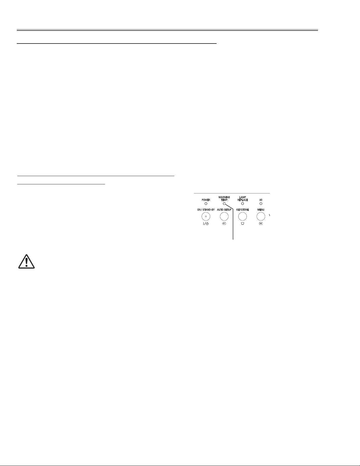
Warning temperature and power failure protection
The projector will be automatically turned off when the internal temperature of the projector is abnormally high, or the
cooling fans stop spinning, or the power supplies in the projector are failed.
- If both of the POWER and WARNING TEMP. indicators are flashing, it may detect the abnormal temperature inside
the projector. Check the following possible causes and wait until the POWER indicator stops flashing, and then try
to turn on the projector.
- If the WARNING TEMP. indicator lights red, it may defect the cooling fans or power supply circuits. Check fans
operation and power supply lines referring to the chapter “Power supply & protection circuit” in the Chassis Block
Diagram section.
Possible causes
- Air filters are clogged with dust particles. Remove dust from the air filters by following instructions in the “Air filter
care and cleaning” below.
- Ventilation slots of the projector are blocked. In such an event, reposition the projector so that ventilation slots are
not obstructed.
- Check if projector is used at higher temperature place (Normal operating temperature is 5 to 40 ˚C or 41 to 104˚F)
The projector is shut down and the WARNING
TEMP. indicator lights red.
When the projector detects an abnormal condition, it is automatically shut down to protect the inside of the projector
and the WARNING TEMP. indicator lights red. In this case,
unplug the AC power cord and reconnect it, and then turn the
projector on once again to verify operation. If the projector
cannot be turned on and the WARNING TEMP. indicator still
lights red, unplug the AC power cord and contact the service
station.
CAUTION
DO NOT LEAVE THE PROJECTOR WITH THE
AC POWER CORD CONNECTED UNDER AN ABNORMAL CONDITION. IT MAY RESULT IN FIRE
OR ELECTRIC SHOCK.
Indicators
WARNING TEMP.
emit a red light
-6-
Page 7
Maintenance
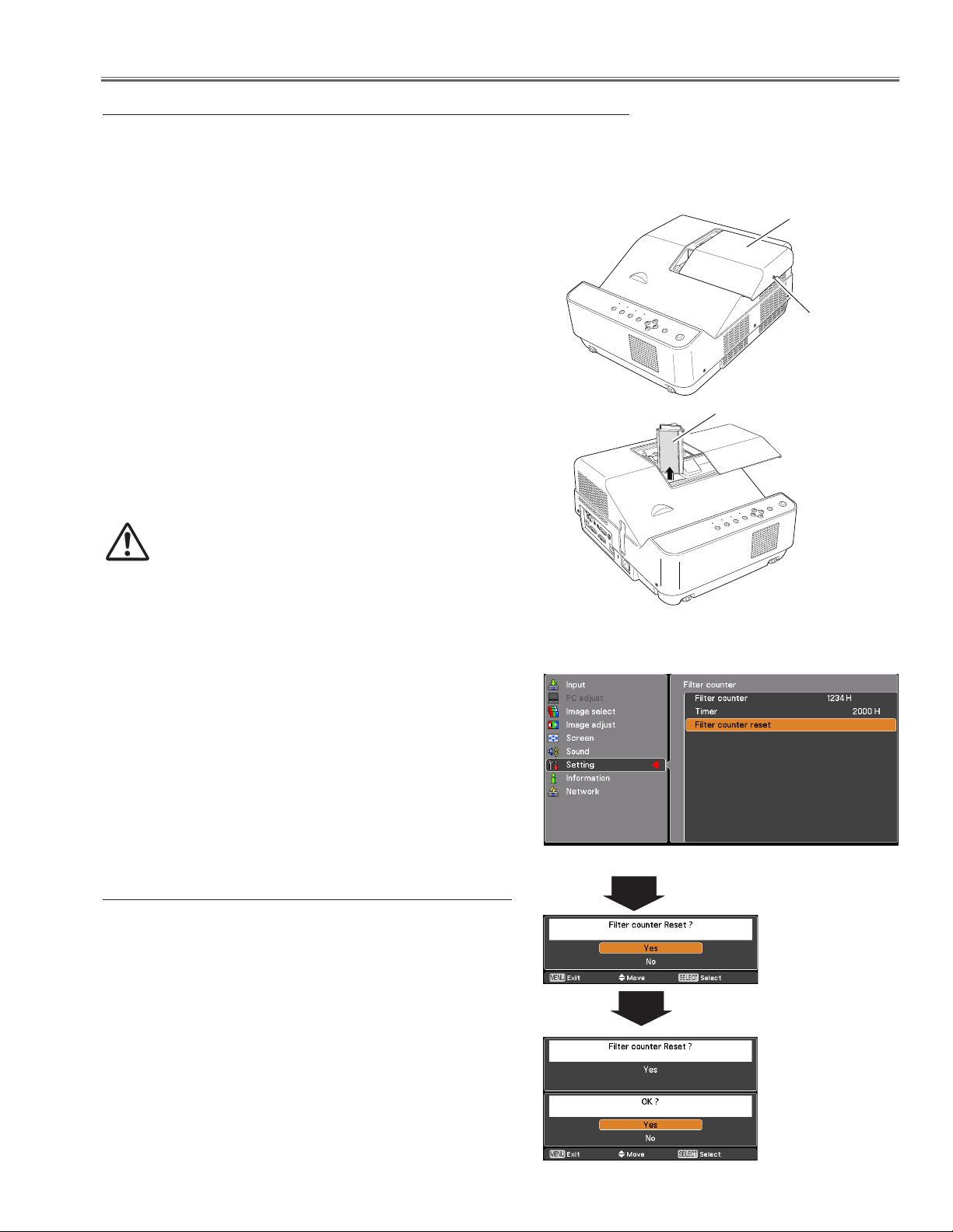
Replacing the Filter
Filter prevents dust from accumulating on the optical elements inside the projector. Should the filter become
clogged with dust particles, it will reduce cooling fans’ effectiveness and may result in internal heat buildup and
adversely affect the life of the projector. If a “Filter warning” icon appears on the screen, replace the filter immediately by following the steps below.
Turn off the projector, and unplug the AC power cord
1
from the AC outlet.
First, clean up the dust on the projector and around the
2
air vents.
Loosen the screw and open the lamp cover and lift the
3
filter out of the projector.
Reinstall the filter completely and close the lamp cover
4
and secure the screw.
Connect the AC power cord to the projector and turn on
5
the projector.
Reset the filter counter.
6
CAUTION
- Do not operate the projector with the filter removed. Dust may accumulate on the optical elements degrading picture quality.
- Do not put anything into the air vents. Doing so
may result in malfunction of the projector.
- Do not wash the filter with water or any other liquid matter. Otherwise the filter may be damaged.
RECOMMENDATION
We recommend avoiding dusty/smoky environments when
you operate the projector. Usage in these environments may
cause poor image quality.
When using the projector under dusty or smoky conditions,
dust may accumulate on a lens, or optical elements inside
the projector degrading the quality of a projected image.
When the symptoms above are noticed, clean up the lens
or other optical parts by referring to the chapter "Cleaning
the projector".
Filter
Filter counter
Lamp cover
Screw
Resetting the Filter Counter
Be sure to reset the Filter counter after replacing the filter.
Press the MENU button to display the On-Screen
1
Menu. Use the Point ed buttons to select Setting and
then press the Point 8 or SELECT button.
Use the Point ed buttons to select Filter counter and
2
then press the Point 8 or the SELECT button. Use the
Point ed buttons to select Filter counter reset and
then press the SELECT button. Filter counter Reset?
appears. Select Yes to continue.
Another confirmation dialog box appears, select Yes to
3
reset the Filter counter.
-7-
Filter counter
Reset? appears.
Select Yes, then
another confirmation
box appears.
Select Yes again to
reset the Filter coun
ter.
-
Page 8
Maintenance
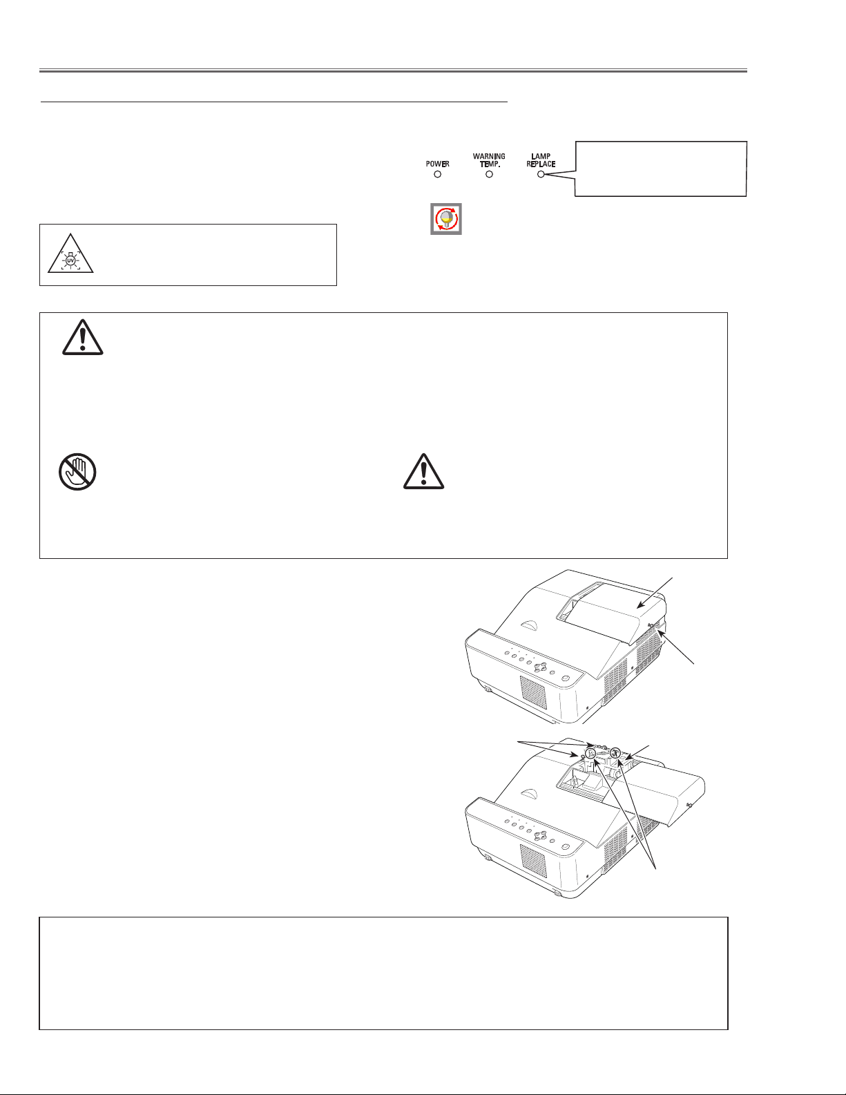
Lamp Replacement
When the projection lamp of the projector reaches its end
of life, the Lamp replacement icon appears on the screen
and LAMP REPLACE indicator lights yellow. Replace the
lamp with a new one promptly. The timing when the LAMP
REPLACE indicator should light is depending on the lamp
mode.
WARNING:
TURN OFF THE UV LAMP BEFORE
OPENING THE LAMP COVER
Top Panel
This indicator turns yellow
when the projection lamp
reaches the end of its life.
Lamp replacement icon
Note:
The Lamp replacement icon will not appear when the
Display function is set to Off, during Freeze, or No show.
CAUTION
When replacing the lamp because it has stopped illuminating, there is a possibility that the lamp may be bro
ken. If replacing the lamp of a projector which has been installed on the ceiling, you should always assume
that the lamp is broken, and you should stand to the side of the lamp cover, not underneath it. Remove the
lamp cover gently. Small pieces of glass may fall out when the lamp cover is opened. If pieces of glass get
into your eyes or mouth, seek medical advice immediately.
CAUTION
Allow a projector to cool for at least 45 minutes
before you open the Lamp Cover. The inside of
the projector can become very hot.
For continued safety, replace with a lamp of the
same type. Do not drop a lamp or touch a glass
bulb! The glass can shatter and may cause injury.
CAUTION
-
Follow these steps to replace the lamp.
Turn off the projector and unplug the AC power cord. Let
1
the projector cool for at least 45 minutes.
Loosen the screw and open the lamp cover.
2
Loosen the two (2) screws that secure the lamp. Lift the
3
lamp out of the projector by using the handle.
Replace the lamp with a new one and secure the two (2)
4
screws. Make sure that the lamp is set properly. Close
the lamp cover and secure the screw.
Connect the AC power cord to the projector and turn on
5
the projector.
Reset the lamp counter.
6
See “Resetting the Lamp Counter” on the next page.
Screws
Lamp Cover
Screw
Lamp
Handle
ORDER REPLACEMENT LAMP
Replacement lamp can be ordered through your dealer. When ordering a projection lamp, give the following
information to the dealer.
Replacement Lamp Type No. : POA-LMP143
Service Parts No. : 610 351 3744
-8-
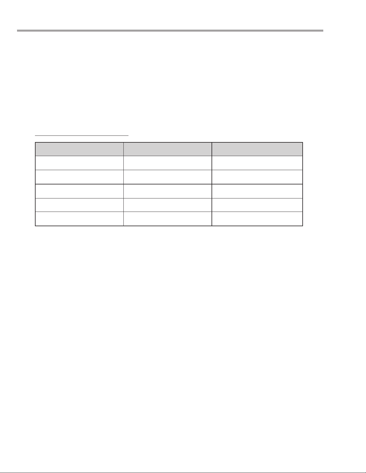
Page 9
Counter
Projector 500H
Lamp
Normal 200 H
Eco 300 H
Corresponding value 600 H
Maintenance
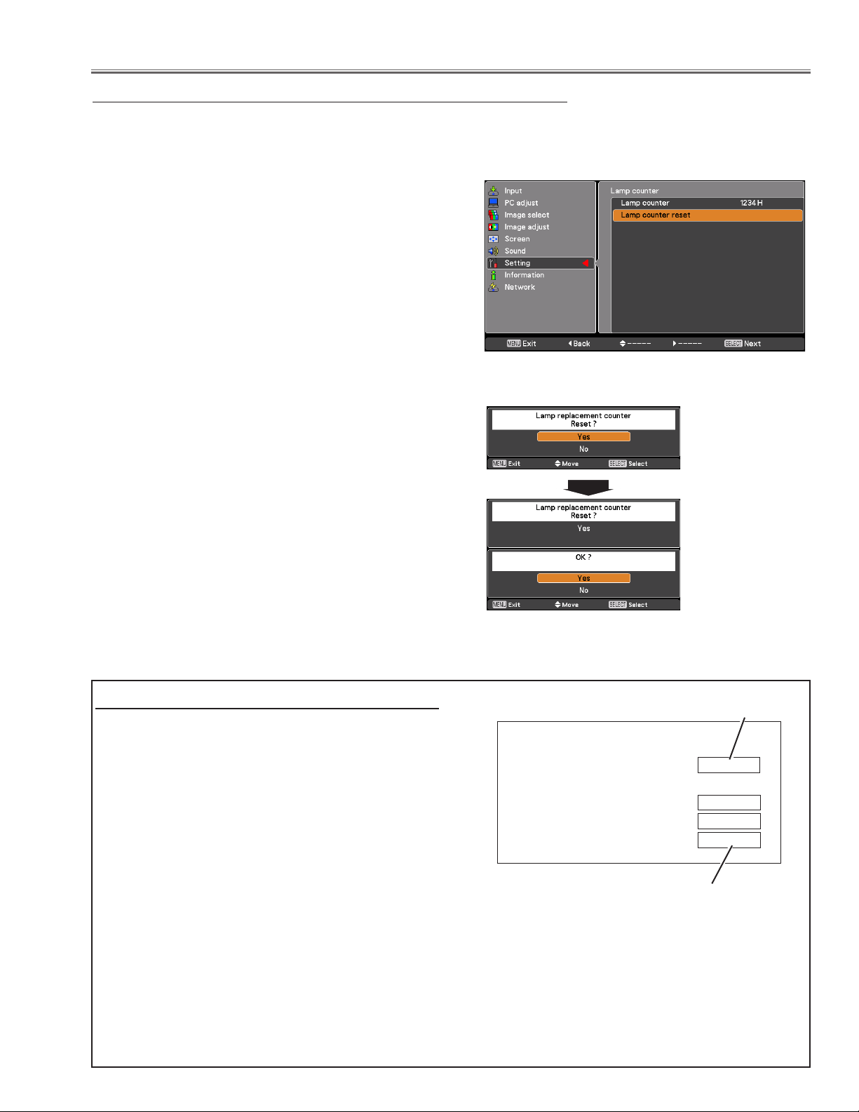
Resetting the Lamp Counter
Be sure to reset the Lamp counter after the lamp is replaced. When the Lamp counter is reset, the LAMP REPLACE
indicator stops lighting and the Lamp replacement icon disappears.
Press the MENU button to display the On-Screen
1
Menu. Use the Point ed buttons to select Setting
and then press the Point 8 or the SELECT button.
Use the Point ed buttons to select Lamp counter
2
and then press the SELECT button. Use the Point ed
buttons to select Lamp counter reset and then press
SELECT button. Lamp replacement counter Reset?
appears. Select Yes to continue.
Another confirmation dialog box appears, select Yes to
3
reset the Lamp counter.
Note:
Do not reset the Lamp counter without implementing lamp
replacement. Be sure to reset the Lamp counter only after
replacing the lamp.
Lamp counter reset
Lamp replacement
counter Reset?
appears.
Select Yes, then
another confirma
tion box appears.
-
How to check Lamp Used Time
The LAMP REPLACE indicator will light yellow when
the total lamp used time (Corresponding value) reaches
3,000 hours. This is to indicate that lamp replacement
is required.
The total lamp used time is calculated by using the below expression,
Total lamp used time (Corresponding value)
= Teco + Tnormal x 1.5
Tnormal : used time in the normal mode
Teco : used time in the eco mode
You can check the lamp used time following to the below procedure.
1 Press and hold the ON/STAND-BY button on the re-
mote control for more than 20 seconds.
2 The projector used time and lamp used time will be
displayed on the screen briefly as follows.
Select Yes again
to reset the Lamp
counter.
Projector used time
Total lamp used time
-9-
Page 10
Maintenance
Cleaning
After long periods of use, dust and other particles will accumulate on the optical parts, mirror, color wheel, lens etc.,
causing the picture to darken or color to blur. If this occurs, remove dust and other particles using air spray. Before
taking the cleaning, turn off the projector and allow the projector to cool for more than 45 minutes. Never disassemble the optical unit, mirror or projection lens because those parts are aligned preciously in the factory . If do so,
the projector may have the miss-alignment in optical and reduce the optical performance.
Cleaning the Color Wheel
- The color wheel is made of thin glass. Be very careful
when handing the color wheel.
- In case of fingerprints, etc. on the surface, gently wipe
with a Cleaning Cloth for optical parts that contains a
small amount of non-abrasive camera lens cleaner to
clean the surface.
- Do not use detergents as this could cause peeling of
the color filter.
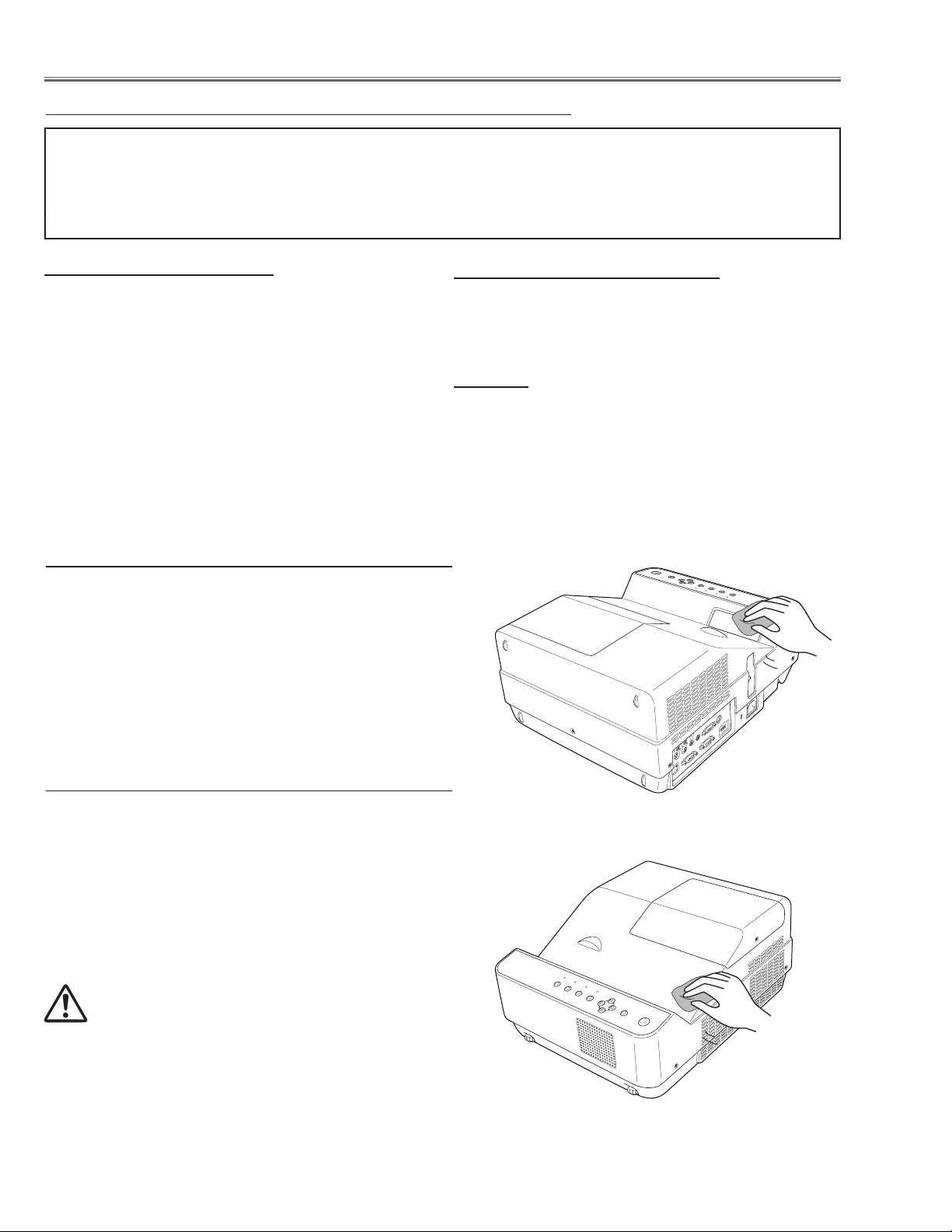
Cleaning the Projection Window
Unplug the AC power cord before cleaning.
First, remove the dust with a commercially available air blower. Then gently wipe the projection window surface. Use a
cleaning paper moistened with methyl alcohol (methanol).
Avoid using an excessive amount of cleaner.
Do not use abrasive cleaners, solvents, or other harsh
chemical cleaners to avoid damaging the projection window.
Cleaning the Reflecting Mirror
- Be careful not to touch the reflecting mirror. Touching
it directly with the hands may cause reducing the burnishing.
- Do not clean other than with air.
Caution:
The optical components may have a crack or spot when
you use the air spray directly to the optical components
while they are in the state of hot. Use a commercial (inert
gas) air spray designed for cleaning camera and computer equipment. Use a resin-based nozzle only. Be very
careful not to damage optical parts with the nozzle tip.
Cleaning the Projector Cabinet
Unplug the AC power cord before cleaning.
Gently wipe the projector body with a soft dry cleaning cloth.
When the cabinet is heavily soiled, use a small amount of
mild detergent and finish with a soft dry cleaning cloth. Avoid
using an excessive amount of cleaner. Abrasive cleaners,
solvents, or other harsh chemicals might scratch the surface of the cabinet.
When the projector is not in use, put the projector in an appropriate carrying case to protect it from dust and scratches.
CAUTION
Do not use any flammable solvents or air sprays on the projector and in its vicinity. The explosion or fire hazard may
occur even after the AC power cord is unplugged because
the temperature inside the projector is extremely high due to
the lamps. In addition, there is a risk that the internal parts
may be damaged not only by the flammable air spray but
also by the cold air.
-10-
Page 11
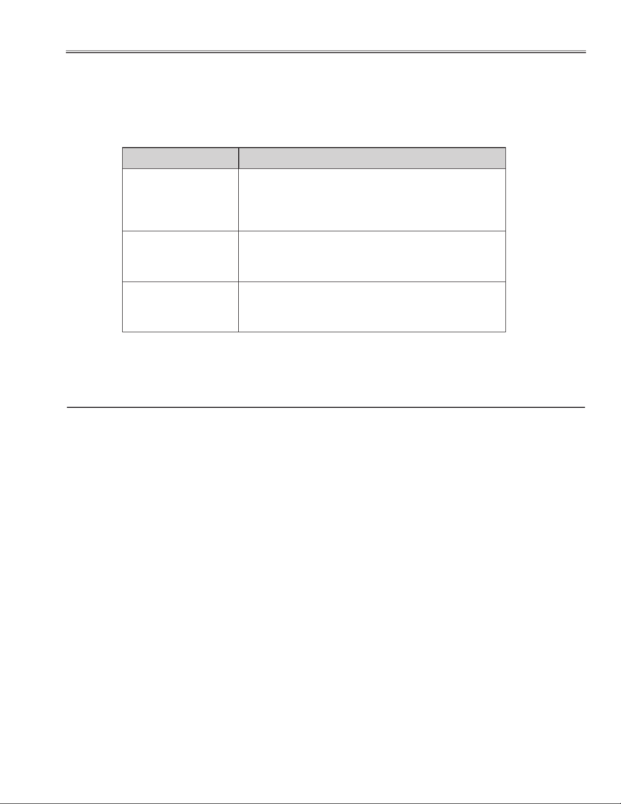
Security Function Notice
This projector provides security functions such as "Key lock", "PIN code lock" and "Logo PIN code lock". When the
projector has set these security function on, you are required to enter correct PIN code to use the projector. If you
do not know the correct PIN code to the projector, the projector can no longer be operated or started. In this case,
you must reset those function first according to the resetting procedure described below and then check up on the
projector.
Function Description
Locks operation of the side control or the remote control.
Key lock
PIN code lock
Logo PIN code lock
If the Key lock is enabled with side control lock, the projector can no longer be started.
Initial setting: Key lock function is disabled
Prevents the projector from being operated by an unauthorized person.
Initial code: “1234”
Prevents an unauthorized person for changing the startup logo on the screen.
Initial code: “4321”
Resetting procedure
1 Disconnect the AC power cord from the AC outlet.
2 As pressing the SELECT button, connect the AC power cord into an AC outlet again.
3 Keep pressing the SELECT button and then press the ON/STAND-BY button.
4 Release the ON/STAND-BY button first and then release the SELECT button.
- The PIN code lock and Logo PIN code lock will be reset as the initial PIN code at the factory and the Key lock
function is disabled.
Please refer to the owner's manual for further information of the security functions.
-11-
Page 12
Standby Mode Notice
This projector provides 2 types of standby mode, Eco standby and Network standby. According to the standby mode
"Eco" or "Network", several functions are restricted as shown in the table below. To change the standby mode, use
the projector's menu "Setting".
Network ............ Supply the power to the network function even after turning off the projector. You can turn on /off
the projector via network, modify network environment, and receive an e-mail about projector status
while the projector is powered off.
Eco ................... Select "Eco" when you do not use the projector via network. The projector's network function will stop
when turning off the projector.
When "Eco" is selected, several functions will be restricted.
Function in the standby mode
Function Eco Network
Serial command control -- *1
Network Function --
Monitor Out --
Audio Out -- --
Direct On
*1 Effective only Power-On command.
4 4
4
4
4
-12-
Page 13
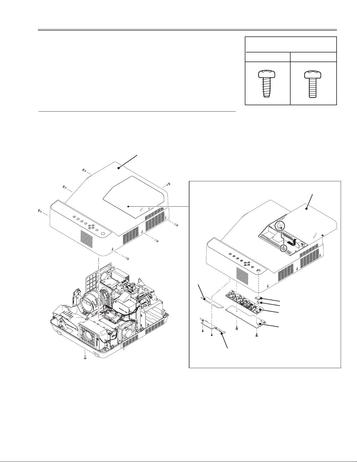
Mechanical Disassembly
Mechanical disassembly should be made following procedures in numerical
order.
Following steps show the basic procedures, therefore unnecessary step may
be ignored.
Caution:
The parts and screws should be placed exactly the same position as the original otherwise it may cause loss of performance and product safety.
z Cabinet Top removal
1. Remove 8 screws A(M3x8) to remove the cabinet top assy upward
off.
Cabinet top assy
A
A
A
A
Screws Expression
(Type Diameter x Length) mm
T type M Type
Lamp cover
A
A
A
A
Optical
filter
RC Window
RC Reflector
Control buttons
Key sw board
(T3x8)x2
(T3x8)x2
Glass holder
Fig.1
-13-
Page 14
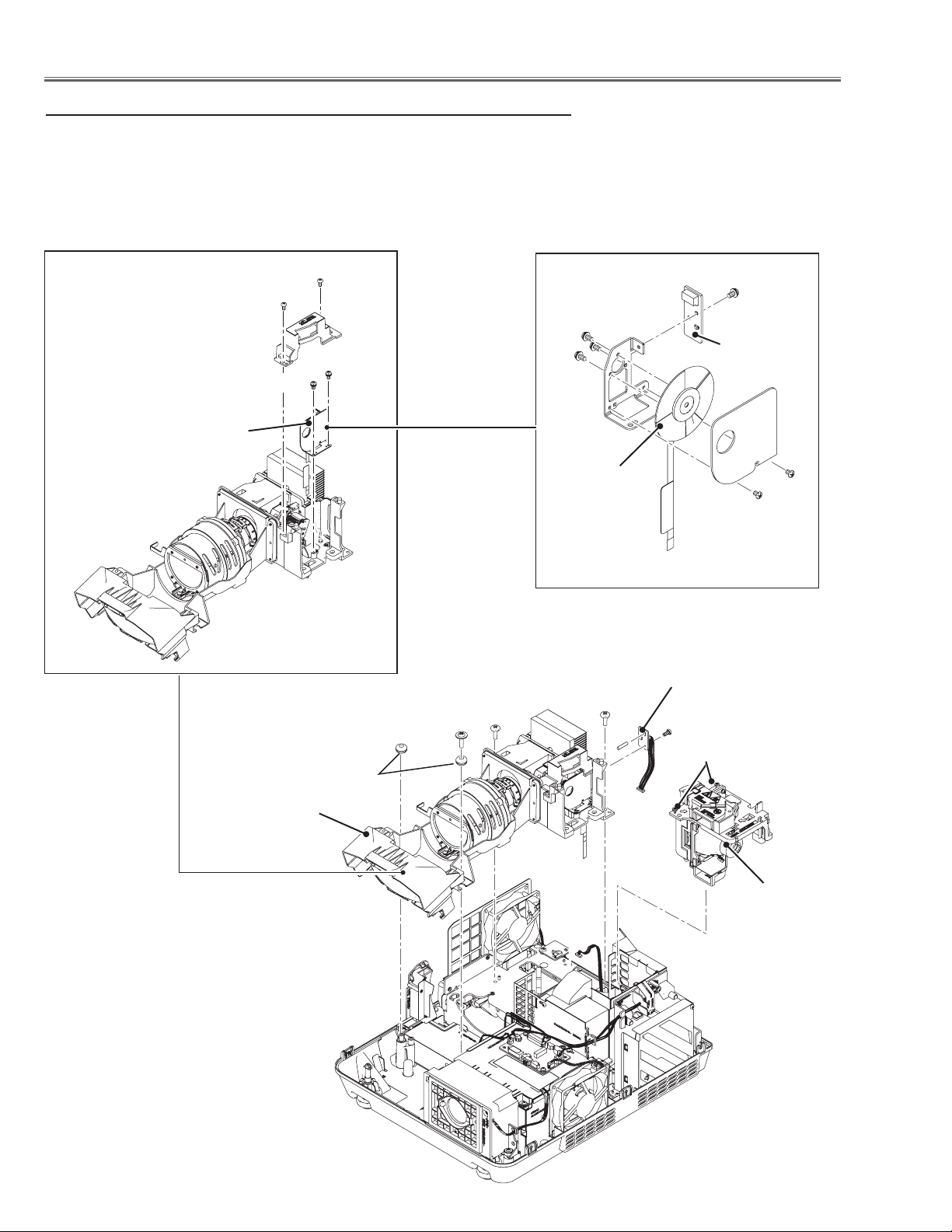
Mechanical Disassembly
x Optical unit Lamp and CW removal
1. Loosen 2 screws A and pull the Lamp assy upward off.
2. Remove 1 screw B(M2.5x6) to remove Temp. Sensor 2 board.
3. Remove 1 screw C(T3x12)x2 and 2 screws D (M4x8) to remove the Optical Unit upward
off.
Color Wheel
assy
(M2x8)x2
(M2x6)x2
(M2x8)x1
(M2x8)x3
CW Sensor
board
Color Wheel
(M2x6)x2
Temp Sensor 2
board
D
C
D
B
Optical unit
Fig.2
A
Bushes
Lamp assy
-14-
Page 15
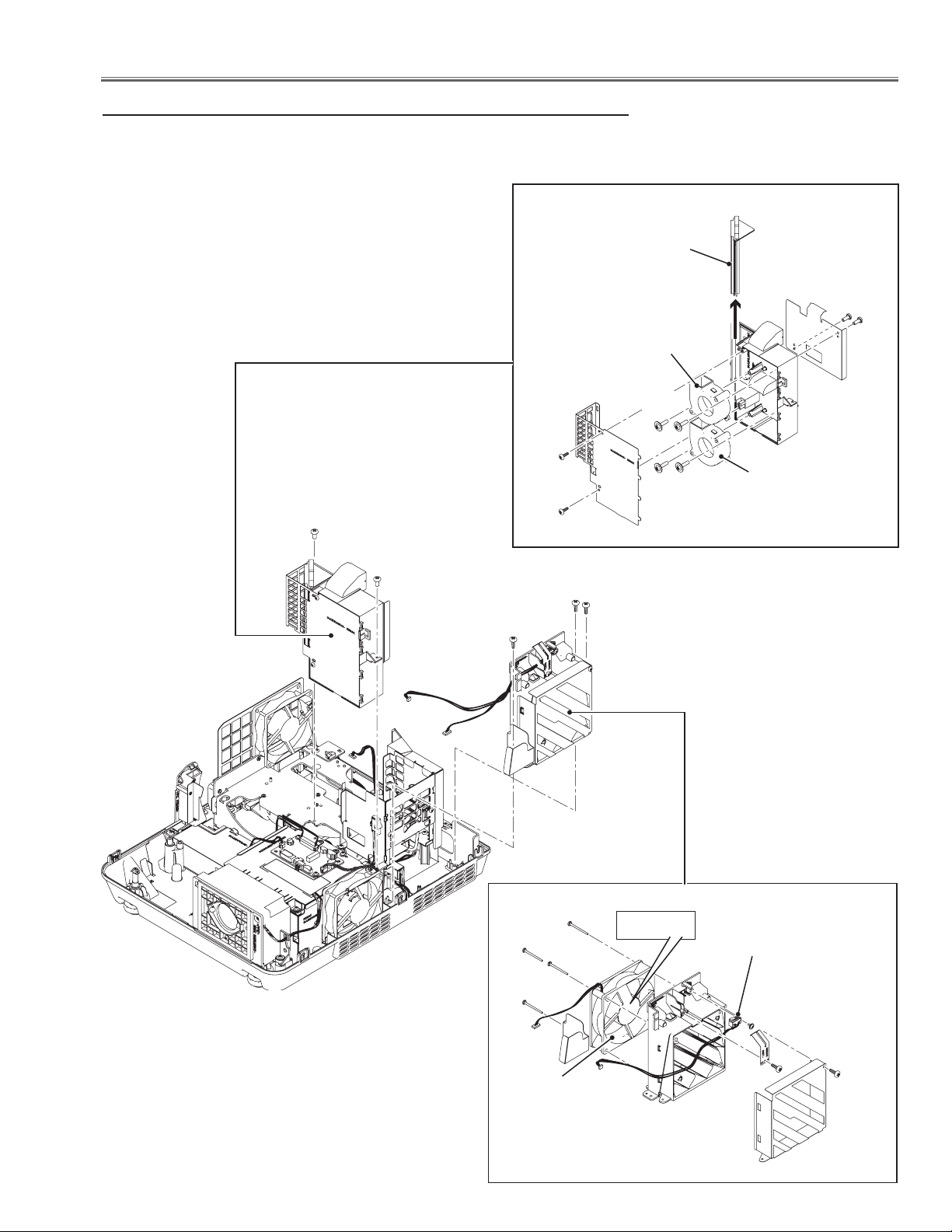
Mechanical Disassembly
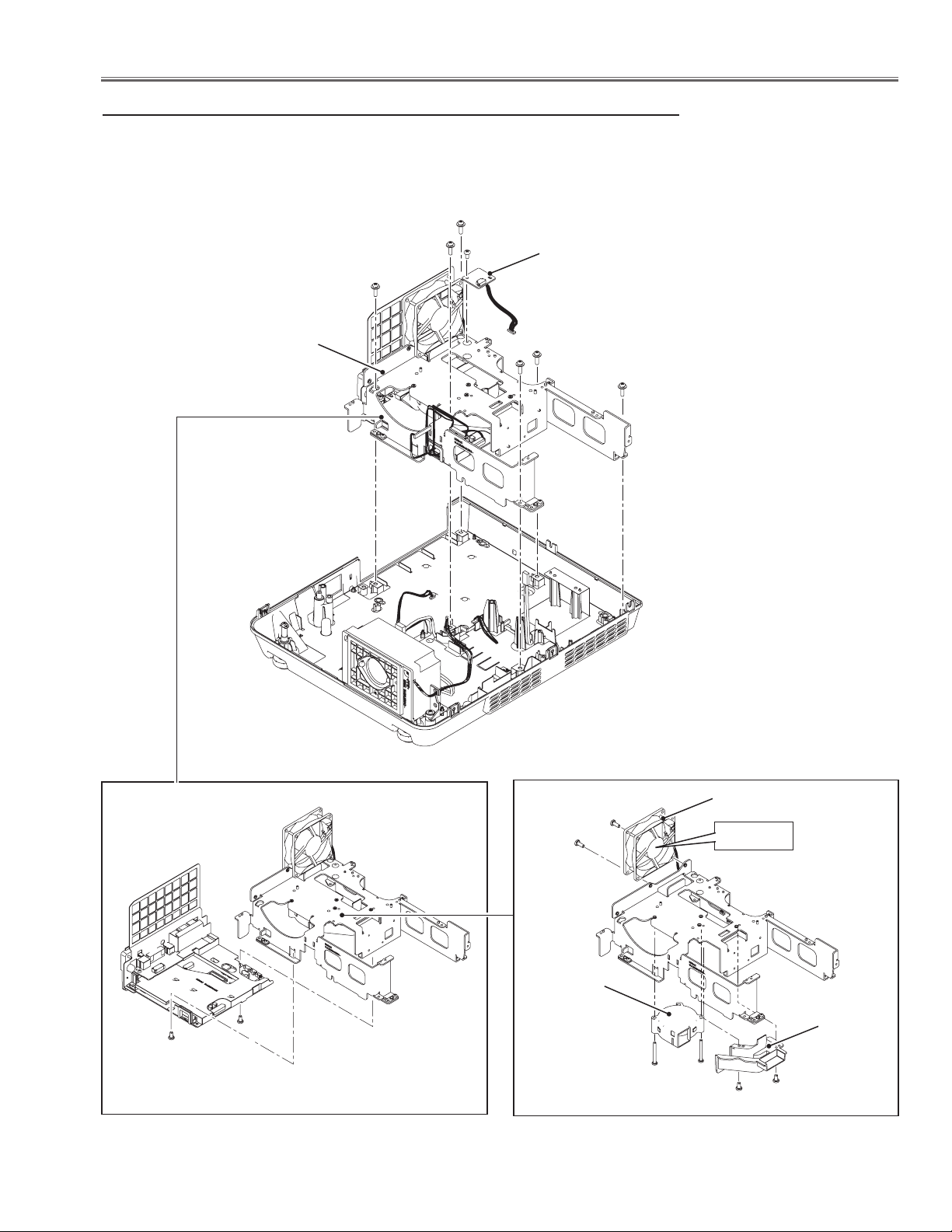
c Fans (FN902, FN903, FN904) and SW901 removal
1. Remove 3 screws A(T3x8) to remove the exhaust fan assy.
2. Remove 2 screws B(M3x6) to remove the fan duct assy.
Air Filter
(T3x8)x2
FN902
(T3x12)x2
Fan duct assy
(T3x8)x2
(T3x12)x2
FN903
B
B
A
A
A
Exhaust fan assy
(T3x32)x4
Label side
SW901
Lamp cover switch
Fig.3
(T3x6)x1
(T3x8)x1
(T3x8)x1
FN904
-15-
Page 16
Mechanical Disassembly
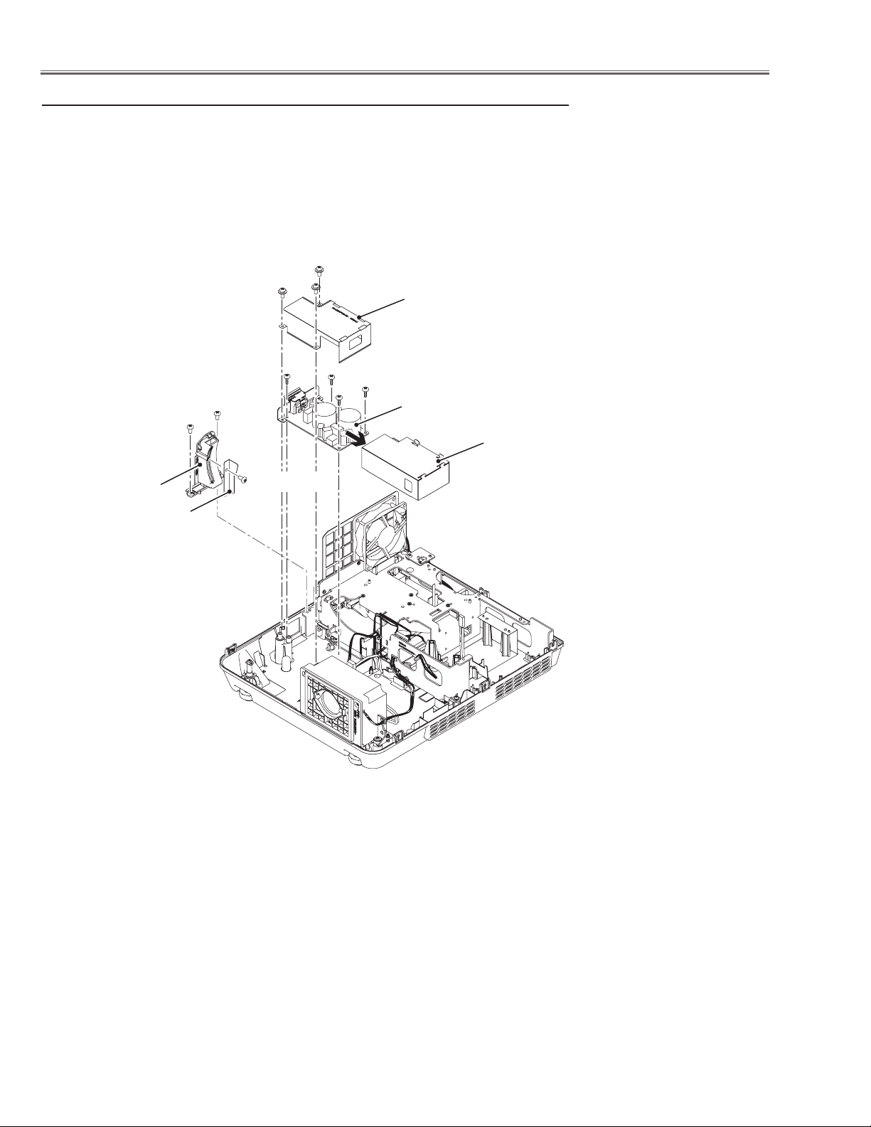
v Power and FanNet Board and fan(FN905) removal
1. Remove 2 screws A(M3x8) to remove the FanNet board.
2. Remove 4 screws B(M3x8) to remove the Power box cover.
3. Remove 2 screws C(M3x8) and 1 screw D(M3x8) to remove the Power board and insulation sheet.
4. Remove 4 screws E(M3x8) to remove the Power box frame assy.
A
A
B
B
B
FanNet Board
B
Power box cover
Fig.4
C
C
Insulation sheet
Power Board
D
E
E
E
Power box frame assy
E
-16-
(M3x10)x3
FN905
Gasket
Label side
Page 17
Mechanical Disassembly
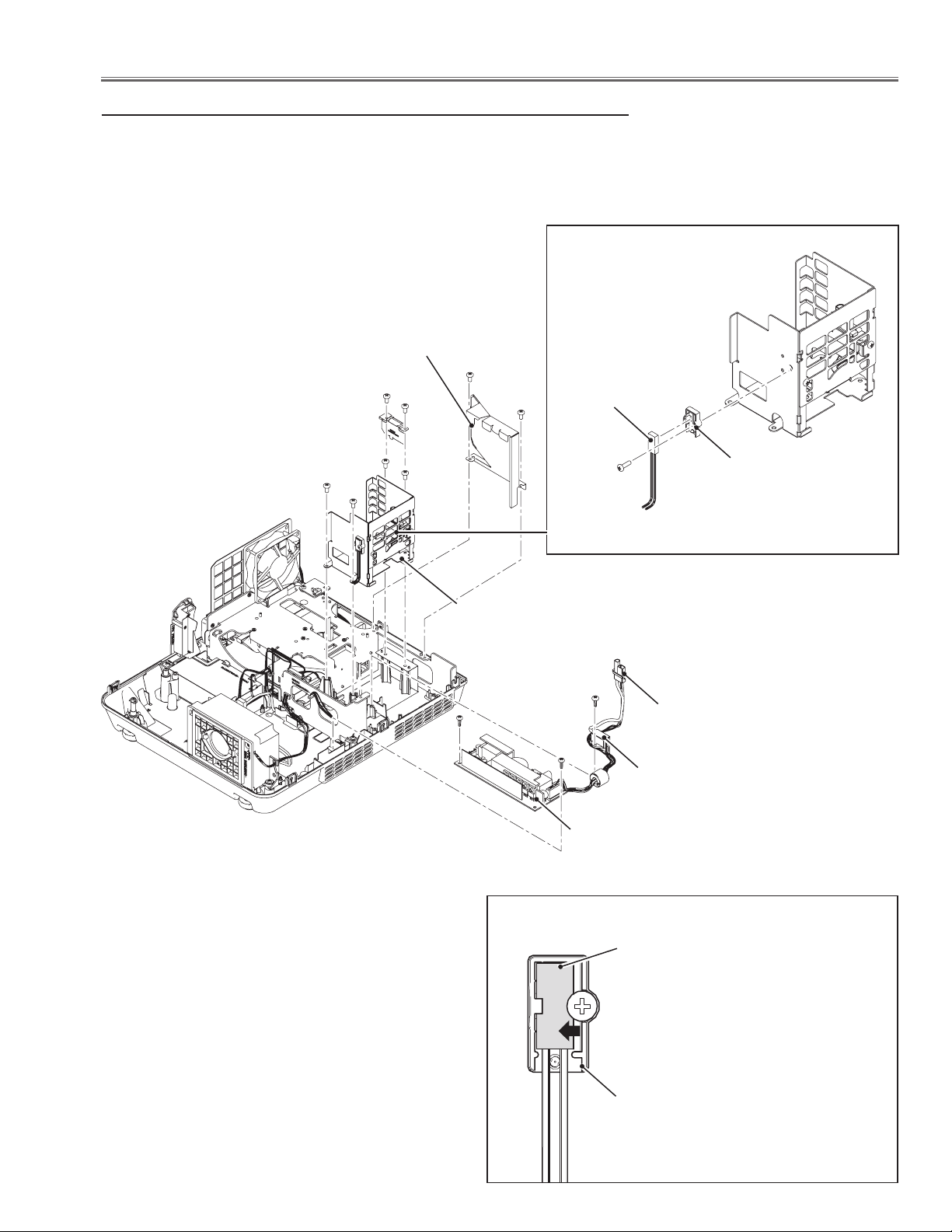
b Ballast Board and Thermal Switch(SW902) removal
1. Remove 2 screws A(M3x6) to remove Side lamp shield.
2. Remove 4 screws B(M3x8) to remove the Lamp house frame.
3. Remove 2 screws C(T3x8) to remove the Ballast board, remove 1 screw
D(T3x8) to remove the Trigger box , remove 2 screws E(M3x6) to remove
the Ballast socket.
Side lamp
shield
E
E
B
B
B
A
A
Thermal switch
SW902
B
(M3x10)x1
Thermal switch
holder
Fig.5
Lamp house
frame
C
Note on mounting the thermal switch (SW902)
D
Socket
C
Trigger box
Ballast board
SW902
Thermal switch
Put the thermal switch on the
holder and slide it in the arrow
direction and then tighten the
screw to fix the thermal switch.
-17-
Thermal switch
holder
Page 18
Mechanical Disassembly
n Line Filter Board removal
1. Remove 2 screw A(M3x6) to remove the Focus lever cover.
2. Remove 3 screws B(M3x8) to remove the Line filter shield.
3. Remove 4 screws C(T3x8) to remove the Line filter board and insulation sheet.
B
Focus lever cover
Spacer
sheet
B
C
A
A
(M2.6x6)x1
B
Line filter shield
C
C
C
Line filter board
Insulation sheet
Fig.6
-18-
Page 19
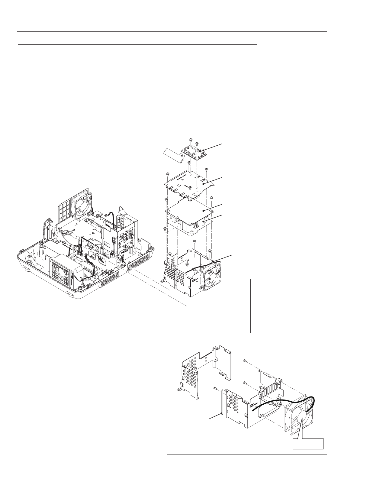
Mechanical Disassembly
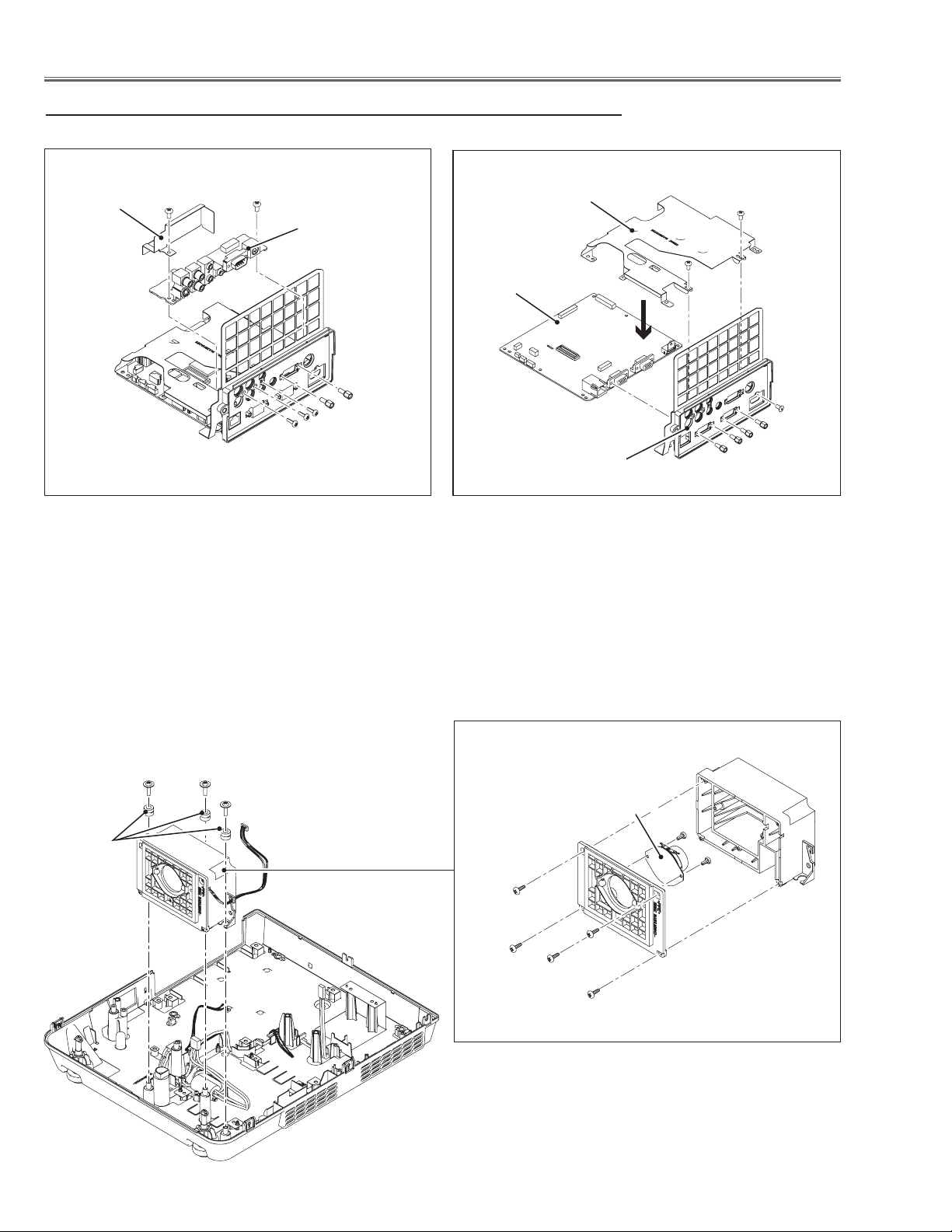
m Main, AV Board and Fans (FN901, FN906) removal-1
1. Remove 1 screw A(M3x6) to remove the Temp. sensor 1 board.
2. Remove 6 screws B(M3x12) to remove the Main and AV board assy.
B
B
A
B
Temp sensor 1 board
Main and AV board
assy
Fig.7
B
B
B
(M3x6)x2
-19-
(M3x10)x2
FN906
FN901
Label side
Fan Duct
(M3x28)x2
(M3x6)x2
Page 20
Mechanical Disassembly
, Main, AV Board and Fans (FN901, FN906) removal-2
Insulation
sheet
(M3x6)x2
AV board
(T3x6)x3
(Hex bolt)
x2
Shield cover
Main board
AV panel
(M3x6)x2
(M3x6)x1
(Hex bolt) x4
Bushes
Fig.8
AA
A
Speaker
(T3x6)x2
(T3x8)x5
-20-
Page 21

Mechanical Disassembly
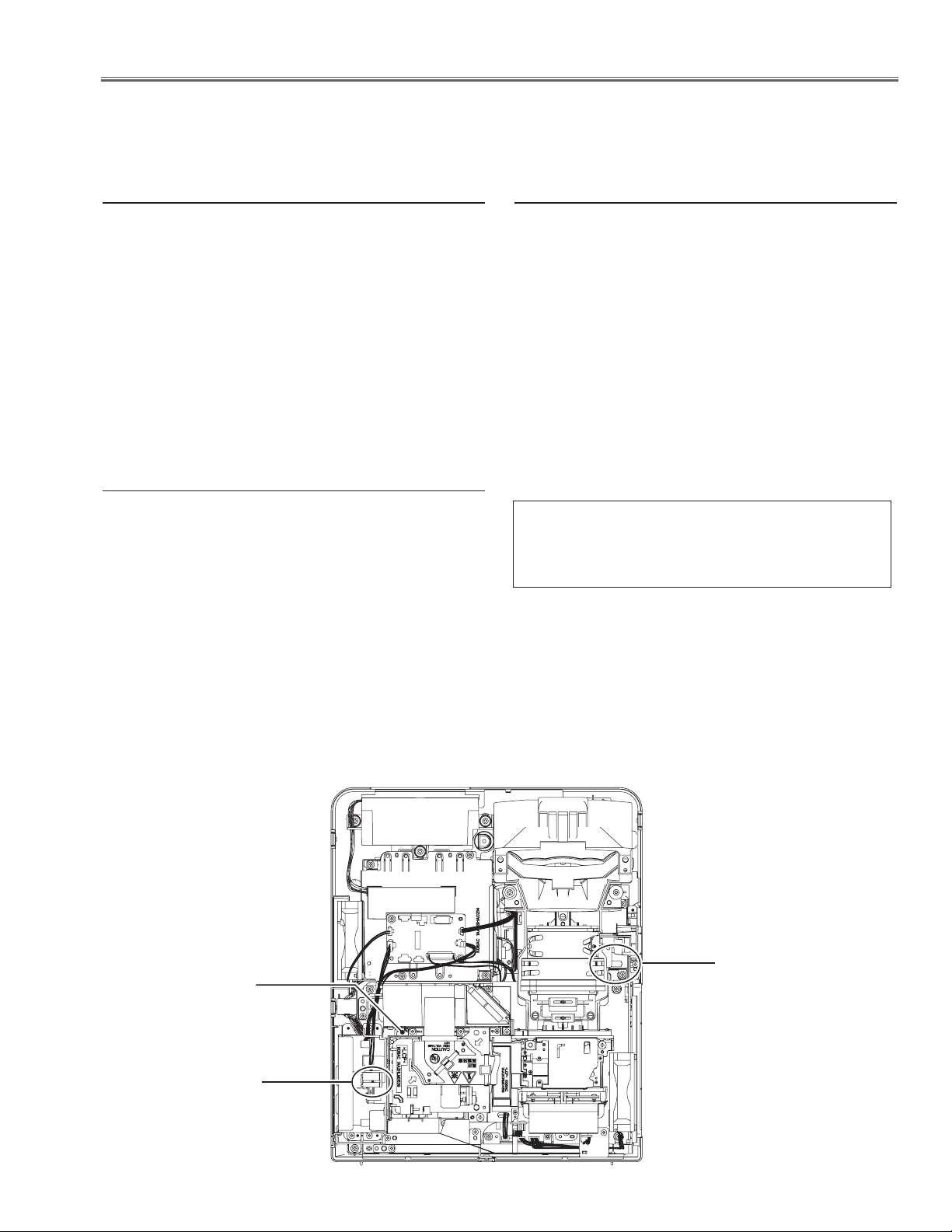
⁄0 Note on wiring
After disassembling the mechanical parts or electrical parts, the wiring cables
must be placed in the original position.
Especially the cable dressing indicated in the figure below, use a fixer not to
touch the cable to the parts on the primary power circuit.
Fix the cables connected to SW902
by using a fixer not to touch the radia
tor on the ballast board.
-
Fig.9
Fix the cables by using a fixer not
to touch the radiator on the ballast
board.
-21-
Page 22
Service Mode
Input Input 1
Image Standard
Group No. Data
0 0 32
Ver. 1.00
Adjustments
Adjustments after Parts Replacement
Optical Unit Color Wheel Power Board Main Board
l : Adjustment necessary ❍ : Check necessary
Disassembly / Replaced Parts
Fan voltage adjustment
Adjustments
Auto calibration adjustment [PC]
Auto calibration adjustment [Component]
Color Index Adjustment-1
Color Index Adjustment-2
Serial no. setting
l l
l
l l
❍
❍
l
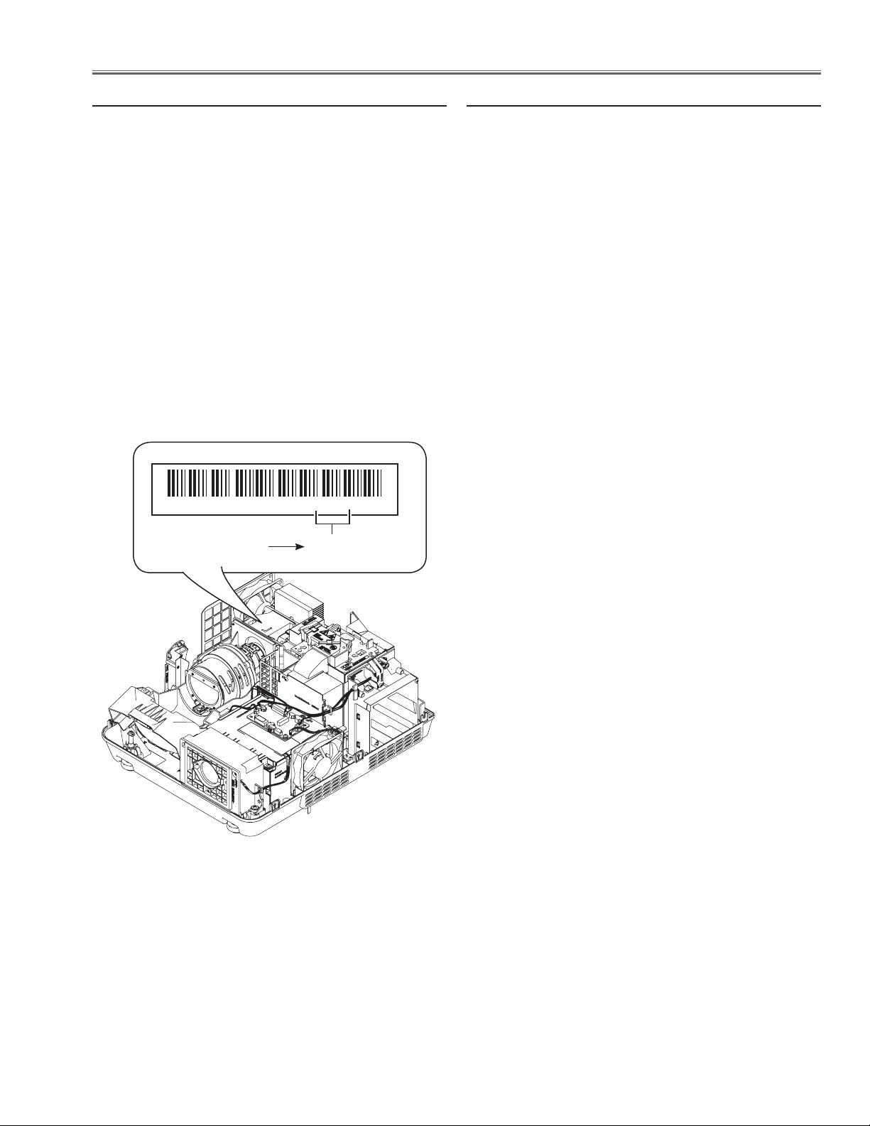
Note on Main Board Replacement
l Memory IC replacement (IC1431)
Memory IC on the main board stores the user control value including lamp used time and product serial no. When
the main board is replaced with new one, the lamp used time and serial no. have a null value. To keep the lamp use
time and serial no., the memory IC should be replaced with the one on the previous main board.
l Serial No. Setting
The serial no. displayed on the on-screen menu "Information" is stored in the memory IC on the main board. After
replacing the memory IC on the main board, if the serial no. on the "Information" menu is not displayed correctly,
use the serial no. setting tool to write the correct serial no. referring to the serial no. printed on the rating label. For
further details, refer to the operation manual of the serial no. setting tool [SST LITE v1.00]. The serial no. setting
tool is included in the service CD-RO below;
PROJECTOR SERVICE TOOL CD-ROM v4.20
SERVICE CODE: 610 343 5596
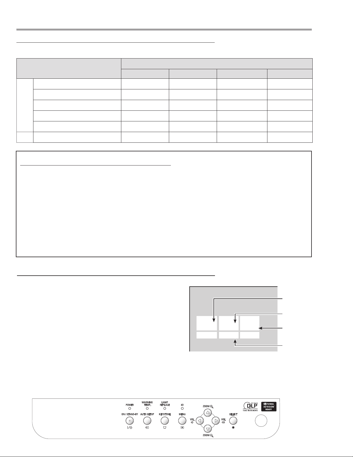
Service Adjustment Menu Operation
To enter the service mode
To enter the “Service Mode”, press and hold the MENU and SELECT button for more than 3 seconds, or press and hold the
MENU button on the remote control for more than 20 seconds.
The service menu appears on the screen as follows.
To adjust service data
Select the adjustment group no. by pressing the MENU button
(increase) or SELECT button (decrease), and select the adjustment item no. by pressing the pointer e or d button, and change
the data value by pressing the 7 or 8 button. Refer to the “Service Adjustment Data Table” for further description of adjustment
group no., item no. and data value.
To exit the service mode
To exit the service mode, press the ON/STAND-BY button.
-22-
Group No.
Item No.
Data value
Firmware
Version No.
Page 23
Adjustments
White 100%
Black 100%
W
Y C
G
M
R
B
BLK
BK-W
BK-R
BK-G
BK-B
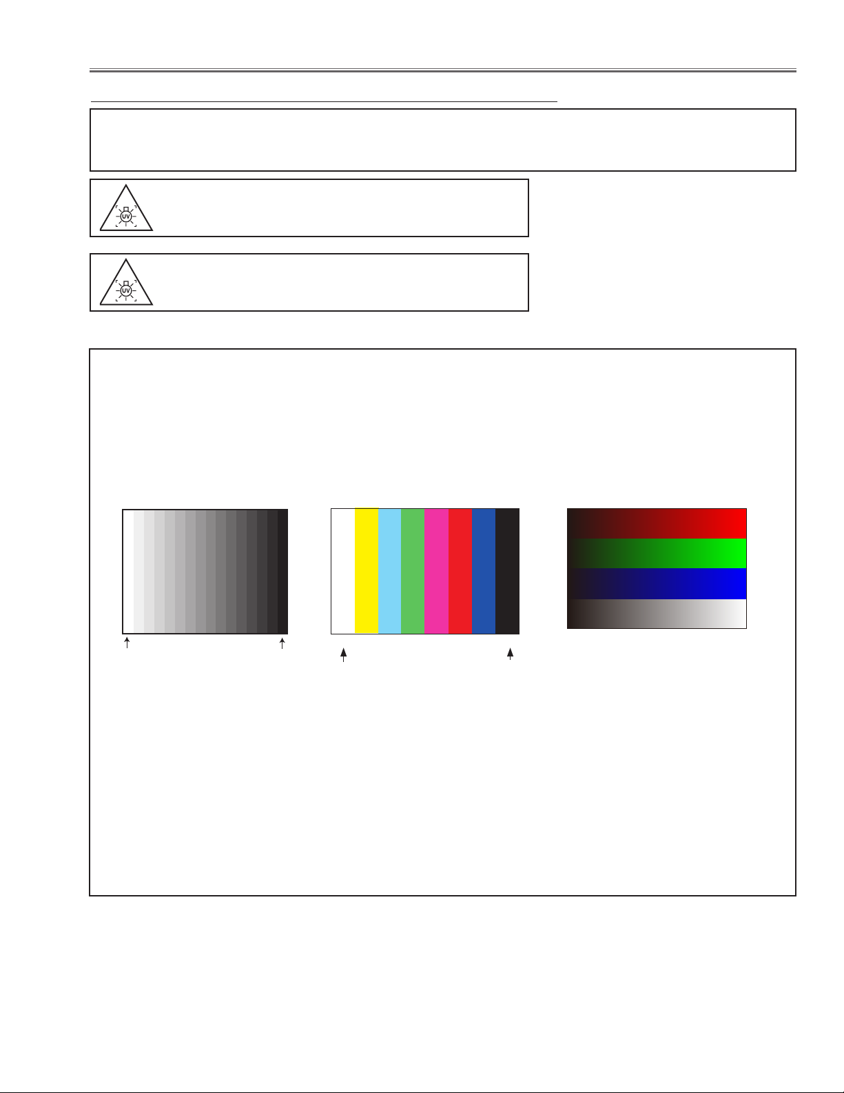
Circuit Adjustments
CAUTION: The each circuit has been made by the fine adjustment at factory. Do not attempt to adjust the following
adjustments except requiring the readjustments in servicing otherwise it may cause loss of performance
and product safety. Before adjustment, please turn on the projector more than ten minutes.
WARNING : USE UV RADIATION EYE AND SKIN
PROTECTION DURING SERVICING.
CAUTION:
To prevent suffer of UV radiation, those adjust
ments must be completed within 25 minutes.
[Adjustment Condition]
l Input signal
Analog Computer signal ..... 0.7Vp-p/75W terminated (XGA)
Composite Video signal ....
Component Video signal .... 0.7Vp-p/75W terminated (480i)
1.0Vp-p/75W terminated (NTSC / PAL)
-
l Input signal patterns
RGBW Ramp pattern
16 steps gray scale pattern
l Image mode ........................
l Lamp control .......................
White 100%
Standard
Normal
8 color 100% color bar
Black 100%
(Internal signal)
l 3D mode ............................ Off
Note:
* Please refer to “Service Adjustment Menu Operation” for entering the service mode and adjusting the service data.
-23-
Page 24
Adjustments
K47A
1
2
49
50
K07A
2
29
30
K07B
K00A
K77B
K77C
K77D
K77E
K77F
K47B
TPFAN1
TPFAN2
TPFAN3
TPFAN4
TPFAN5
TPFAN6
TPFANGND
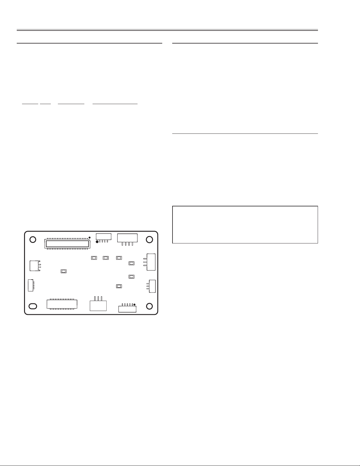
z Fan Voltages adjustment
Equipment Digital voltmeter
1. Enter the service mode.
2. Connect the Digital voltmeter to the test point listed
below.
3. Adjust the voltage on each test point by changing the
data values of the Group - No.
Group No. Test Point Adjustment value
250 - 0 TPFAN1 4.5 -0 +0.1Vdc
250 - 1 TPFAN1 13.8 -0 +0.1Vdc
250 - 2 TPFAN1 4.5 -0 +0.1Vdc
250 - 3 TPFAN2 13.8 -0 +0.1Vdc
250 - 4 TPFAN3 4.5 -0 +0.1Vdc
250 - 5 TPFAN3 13.8 -0 +0.1Vdc
250 - 6 TPFAN4 4.5 -0 +0.1Vdc
250 - 7 TPFAN4 13.8 -0 +0.1Vdc
250 - 8 TPFAN5 4.5 -0 +0.1Vdc
250 - 9 TPFAN5 13.8 -0 +0.1Vdc
250 - 10 TPFAN6 4.5 -0 +0.1Vdc
250 - 11 TPFAN6 13.8 -0 +0.1Vdc
x PC Auto calibration
Input mode Computer 1 (RGB) mode
Input signal 16-step gray scale computer signal
1. Enter the service mode.
2.
Select Group "260", No. "0" and set data value "0" to
"1".
The projector begins auto-calibration and then "OK"
will appear on the screen.
c
Component Auto calibration
Input mode Computer 1 (Component) mode
Input signal 100% color bar signal (480i)
1. Enter the service mode.
2.
Select Group "260", No. "0" and set data value "0" to
"1".
The projector begins auto-calibration and then "OK"
will appear on the screen.
FANNET Board
Adjustments item no. [2] to [3] are carried out at the
spare parts shipment in the factory, therefore they are
not required when the main board is replaced with
new one.
-24-
Page 25
Adjustments
�
9 0 0 0 0 0 0 0 0 2 W 0 7 0
�
“ 0 7 0 ”
v Color Index adjustment-1
Condition Dark room
Input mode Computer 1 (RGB) mode
Image mode Dynamic
Input signal RGBW-Ramp pattern (Internal sig-
nal)
1. Enter the service mode.
2.
Select Group "151", No. "21" and set data value to
"1". The RGBW-Ramp internal pattern is displayed on
the screen.
3.
Select Group "151", No. "0" and set data value to the
specified index value which is printed on the label of
the optical unit.
4. Check that the proper gradation color image is reproduced on the screen.
* Only this adjustment is needed when the Optical unit or
Main board is replaced.
Label on the optical unit
b Color Index adjustment-2
Condition Dark room
Input mode Computer 1 (RGB) mode
Image mode Dynamic
Input signal RGBW-Ramp pattern (Internal sig-
nal)
1. Enter the service mode.
2.
Select Group "151", No. "21" and set data value to
"1". The RGBW-Ramp internal pattern is displayed on
the screen.
3.
Select Group "151", No. "0" and change data value to
obtain the proper gradation color image is reproduced
on the screen
* Only this adjustment is needed when the Color Wheel
is replaced.
3-digit index value
-25-
Page 26

Adjustments
Service Adjustment Data Table
These initial values are the reference data written from the CPU
ROM to memory IC when replaced new memory IC. The adjust
ment items indicated with “
to the “Electrical adjustments”. Other items should be used with
the initial data value.
Group/
Group 0 AD Converter (AF1000)
Group 60 Image
Item Name Function Initial Range Note
Item
0 Green Offset PC / Component 512/512 0 - 4095
1 Red Offset PC / Component 512/512 0 - 4095
2 Blue Offset PC / Component 512/512 0 - 4095
3 Green Coarse Gain PC / Component 7/7 0 - 15
4 Red Coarse Gain PC / Component 7/7 0 - 15
5 Blue Coarse Gain PC / Component 7/7 0 - 15
6 Green Fine Gain PC / Component 0/0 0 - 255
7 Red Fine Gain PC / Component 0/0 0 - 255
8 Blue Fine Gain PC / Component 0/0 0 - 255
9 SCART SOG Thresh SCART only 12 0 - 31
0 Center Contrast
1 Center Brightness
2 Center Color
3 Center Tint
4 Fixed Sharpness (Up scaling)
5 Fixed Sharpness (Down scaling)
6 Center Sharpness (not FPGA)
7 Center WB Red
8 Center WB Green
9 Center WB Blue
10 Center BB Red
11 Center BB Green
12 Center BB Blue
13 Alpha Contrast
14 Alpha Brightness
15 Alpha Color
16 Alpha Tint
17 Alpha Sharpness
18 Alpha WB Red
19 ALpha WB Green
20 Alpha WB Blue
21 Alpha BB Red
22 Alpha BB Green
23 Alpha BB Blue
Group:
Composite/S-Video/Component/Digital/D-RGBVideo/Alanou RGB
RGB-Video/HDCP-PC/HDCP-AV/SCART
98/98/106/98/98/106
106/98/98/106/100
0/0/0/0/0/0
0/0/0/0/0
100/100/100/100100/100
100/100/100/100/100
0/0/0/0/00
0/0/0/0/0
8/8/8/12/8/12
8/12/8/8/8
8/8/8/8/8/8
8/8/8/8/8
16/16/16/16/16/16
16/16/16/16/16
512/512/512/512/512/512
512/512/512/512/512
512/512/512/512/512/512
512/512/512/512/512
512/512/512/512/512/512
512/512/512/512/512
512/512/512/512/512/512
512/512/512/512/512
512/512/512/512/512/512
512/512/512/512/512
512/512/512/512/512/512
512/512/512/512/512
60/60/60/60/60/60
60/60/60/60/60
90/90/90/90/90/90
90/90/90/90/90
40/140/140/140/140/140
140/140/140/140/140
10/10/10/10/10/10
10/10/10/10/10
10/10/10/10/10/10
10/10/10/10/10
40/40/40/40/40/40
40/40/40/40/40
40/40/40/40/40/40
40/40/40/40/40
40/40/40/40/40/40
40/40/40/40/40
20/20/20/20/20/20
20/20/20/20/20
20/20/20/20/20/20
20/20/20/20/20
20/20/20/20/20/20
20/20/20/20/20
-
✻” are required to readjust following
0 - 1023
0 - 1023
0 - 1023
0-180
0 - 37
0 - 37
0 - 37
0 - 1023
0 - 1023
0 - 1023
0 - 1023
0 - 1023
0 - 1023
0 - 1000
0 - 1000
0 - 1000
0 - 1000
0 - 1000
0 - 1000
0 - 1000
0 - 1000
0 - 1000
0-1000
Group 151 Color Wheel
0 Index Delay Index Value of Color Wheel 70 0 - 360
20 Raster Pattern
0: Off
1: Blue Back 2: Green Back
3: Red Back 4: Black Back
5: White Back 6: 60% Blue Back
7: 10% Gray Back 8: 30% Gray Back
9: 50% Gray Back 10: Cyan Back
11: Magenta Back 12: Yellow Back
0 0 - 12
-26-
Page 27

Adjustments
Group/
Group 155 CCA
Group 156 Color Matching - Measured Data
Group 160 Waveform Index
Item Name Function Initial Range Note
Item
21 Test Pattern
0 CCA Disable 0: CCA Enable, 1: Disable 0 0 - 1
0 Measured Red -X
1 Measured Red -Y 0 - 1000
2 Measured Red -Luma 0 - 32767
10 Measured Green -X 0 - 1000
11 Measured Green -Y 0 - 1000
12 Measured Green -Luma 0 - 32767
20 Measured Blue -X 0 - 1000
21 Measured Blue -Y 0 - 1000
22 Measured Blue -Luma 0 - 32767
70 Measured Full White -X 0 - 1000
71 Measured Full White -Y 0 - 1000
72 Measured Full White -Luma 0 - 32767
100 measured Data Update
120 Measured Test Pattern OFF / Red / Green / Blue / Full White 0 - 4
0 Bright Image Mode Image = Dynamic 0 0 - 10
1 Normal Image Mode Image = Standard 0 0 - 10
2 Color Image Mode Image = Cinema 0 0 - 10
3 Normal 120Hz 120Hz Mode 0 0 -10
4 3D Image Mode 3D Mode 0 0 - 10
0: Off 1: Color Ramp
2: Color Bar 3: 16 step
4: Grid 5: Green Grid
6: 1-line Pattern 7: 1-dot Pattern
8: BC Calibration 9: Half Cross
Adjust Color matching Data
0: Image = Dynamic mode
1: Image = Standard mode
2: Image = Cinema mode
3: 120Hz Output mde
4: 3D mode
* This data will be effective after executing the
item 100.
Update the Measured Data when the value is
set to 10.
0 0 - 9
0 - 1000
0 - 10
Group 161 Lamp Sync Delay
0 Bright Image Mode Image = Dynamic 190 0 - 32767
1 Normal Image Mode Image = Standard 190 0 - 32767
2 Color Image Mode Image = Cinema 190 0 - 32767
3 Normal 120Hz 120Hz Mode 190 0 - 32767
4 3D Image Mode 3D Mode 190 0 - 32767
Group 200 Option
0
Logo Prohibition (Forced No Brand)
1 RS232C Baudrate Baud Rate 0: 19200bps, 1: 9600bps 0 0 - 1
4 CABLE SW Long Cable 0: Disable, 1: Enable 0 0 - 1
5 PW Debug Command Enable
8 Network Hung up Check 0: Enable, 1: Disable 0 0 - 1
51 Filter Warning Display Filter Waring Display On/Off 0: Off, 1: On 1 0 - 1
53 Filter Counter Reset Times Reset Times 0 0 - 255
54 Factory Default Execute Times Reset Times 0 0 - 255
63 Source Search Enable Siurce Search Enable o: Disable, 1: Enable 1 0 - 1
80 Destination Setting Shipping Destination 0: English, 1: Japanese 0 0 - 1
111 Sound Mute 0: work alone, 1: Work with Video Mute 1 0 - 1
120 HDMI CONT
Group 201 Option (signal)
0 VSBEG 8 0 - 255
Group 220 Error Log
0 Waring Log 1 Latest Error Log 0 0 - 32767
~ Warning Log x th x th old Error Log 0 0 - 32767
49 Warinig Log 50 50th old Error Log 0 0 - 32767
50 Warinig Log Reset
Logo Prohibition (0: Menu, 1: Forced, 2: China,
3-9: not used) Effective after AC On
0:Disable (Serial Command Eanble)
1: Enable (PW Debug Mode)
0: EDID/HPD Manual Control in the Standby
1: EDID/HPD Auto Control in the Standby
Resets All Warning Logs when the value is set
to 10.
0 0 - 2
0 0 - 1
1 0 - 1
0 0 - 10
Group 250 FAN Voltage Adjustment
0 Fan1 Min. Adjust (DAC) 25 0 - 255
1 Fan1 Max. Adjustt(DAC) 235 0 - 255
2 Fan2 Min. Adjust (DAC) 27 0 - 255
3 Fan2 Max. Adjust (DAC) 237 0 - 255
-27-
Page 28
Adjustments
L3
L2
L4
L1
Group/
Group 252 Fan Option
Item Name Function Initial Range Note
Item
4 Fan3 Min. Adjust (DAC) 31 0 - 255
5 Fan3 Max. Adjust (DAC) 234 0 - 255
6 Fan4 Min. Adjust (DAC) 27 0 - 255
7 Fan4 Max. Adjust (DAC) 237 0 - 255
8 Fan5 Min. Adjust (DAC) 28 0 - 255
9 Fan5 Max. Adjust (DAC) 239 0 - 255
10 Fan6 Min. Adjust (DAC) 28 0 - 255
11 Fan6 Max. Adjust (DAC) 238 0 - 255
1 Safety Switch For Safety Application purpose 0 0 - 4
2 Fan Manual Switch 0: Auto, 1: Manual 0 0 - 1
3 Fan1 Manual Voltage Fan1 Voltage (x0.1V) 100 0 - 145
4 Fan2 Manual Voltage Fan2 Voltage (x0.1V) 100 0 - 145
5 Fan3 Manual Voltage Fan3 Voltage (x0.1V) 100 0 - 145
6 Fan4 Manual Voltage Fan4 Voltage (x0.1V) 100 0 - 145
7 Fan5 Manual Voltage Fan5 Voltage (x0.1V) 100 0 - 145
8 Fan6 Manual Voltage Fan6 Voltage (x0.1V) 100 0 - 145
9 All Fan MaxMin Control
Forced Fan Mode
0: Normal, 1: Normal-Min, 2: Normal-Max,
3: Eco-Min, 4: Eco Mox
0 0 - 4
Group 253 FAN Error Setting
L1
0 Temp A Warning (Normal)
1 Temp B Warning (Normal)
2 Temp C Warning (Normal)
3 Temp B-A Waninig (Normal)
4 Temp C-A Warning (Normal)
5 Temp A Warning (Eco)
6 Temp B Warning (Eco)
7 Temp C Warning (Eco)
8 Temp B-A Warninig (Eco)
9 Temp C-A Warning (Eco)
10 Temp A Warning Offset (Temp) 12 0 - 100
11 Temp B Warning Offset (Temp) 11 0 - 100
12 Temp C Warning Offset (Temp) 13 0 - 100
13 Temp B-A Warning Offset (Temp) 11 0 - 100
14 Temp C-A Warning Offset (Temp) 13 0 - 100
15 Temp A Warning Offset (Time) 30 0 - 40
16 Temp B Warning Offset (Time) 15 0 - 40
17 Temp C Warning Offset (Time) 15 0 - 40
18 Temp B-A Warning Offset (Time) 15 0 - 40
19 Temp C-A Warning Offset (Time) 15 0 - 40
Temperature A to judge the Temp. Failure
Outside at Normal
Temperature B to judge the Temp. Failure DMD
at Normal
Temperature C to judge the Temp. Failure Lamp
at Normal
Temperature B-A to judge the Temp. Failure
Filter Clogged at Normal
Temperature C-A to judge the Temp. Failure
Filter Clogged at Normal
Temperature A to judge the Temp. Failure
Outside at Eco
Temperature B to judge the Temp. Failure DMD
at Eco
Temperature C to judge the Temp. Failure Lamp
at Eco
Temperature B-A to judge the Temp. Failure
Filter Clogged at Eco
Temperature C-A to judge the Temp. Failure
Filter Clogged at Eco
NormalL2CeilingL3BottomL4Up
48 48 48 48 30 - 100
68 67 67 68 30-100
68 67 68 68 30-100
100 100 100 100 0-100
100 100 100 100 0-100
50 49 49 49 30 - 100
71 71 70 70 0 - 100
73 72 73 73 0 - 100
100 100 100 100 0 - 100
100 100 100 100 0 - 100
-28-
Page 29

Adjustments
Group/
Group 254 FAN Control Range Setting (Temp./Voltage)
Item Name Function Initial Range Note
Item
L1
0 Normal Fan Control Min. Temp Temp Sensor Control Start/End at Normal 27 27 27 27 20 - 100
1 Normal Fan Control Max. Temp 36 36 36 36 20 - 100
2 Normal Fan1 Min. Fan Voltage at Normal (x0.1V) 62 62 62 62 0 - 255
3 Normal Fan1 Max. 138 138 138 138 0 - 255
4 Normal Fan2 Min. 90 70 105 55 0 - 255
5 Normal Fan2 Max. 95 70 110 70 0 - 255
6 Normal Fan3 Min. 75 95 55 115 0 - 255
7 Normal Fan3 Max. 75 105 75 120 0 - 255
8 Normal Fan4 Min. 80 80 80 80 0 - 255
9 Normal Fan4 Max. 138 138 138 138 0 - 255
10 Normal Fan5 Min. 75 78 78 75 0 - 255
11 Normal Fan5 Max. 138 138 138 138 0 - 255
12 Normal Fan6 Min. 55 55 55 55 0 - 255
13 Normal Fan6 Max. 135 135 135 135 0 - 255
16 Eco Fan Control Min. Temp Temp Sensor Control Start/End at Eco 27 27 27 27 20 - 100
17 Eco Fan Control Max. Temp 37 37 37 37 20 - 100
18 Eco Fan1 Min. Fan Voltage at Eco (x0.1V) 60 60 60 60 0 - 255
19 Eco Fan1 Max. 70 70 70 70 0 - 255
20 Eco Fan2 Min. 60 50 60 45 0 - 255
21 Eco Fan2 Max. 70 55 70 50 0 - 255
22 Eco Fan3 Min. 50 65 50 65 0 - 255
23 Eco Fan3 Max. 55 75 55 75 0 - 255
24 Eco Fan4 Min. 60 60 60 60 0 - 255
25 Eco Fan4 Max. 120 120 120 120 0 - 255
26 Eco Fan5 Min. 52 55 55 52 0 - 255
27 Eco Fan5 Max. 110 110 110 110 0 - 255
28 Eco Fan6 Min. 50 50 50 50 0 - 255
29 Eco Fan6 Max. 115 115 115 115 0 - 255
NormalL2CeilingL3BottomL4Up
Group 255 FAN Start/Cooling Setting
0 Fan1 Initial Volt Fan Voltage at Startup (x0.1V) 70 0 - 255
1 Fan2 Initial Volt 60 0 - 255
2 Fan3 Initial Volt 60 0 - 255
3 Fan4 Initial Volt 65 0 - 255
4 Fan5 Initial Volt 70 0 - 255
5 Fan6 Initial Volt 60 0 - 255
7 Cooling Time L1 Cooling Time at L1 (x 30 sec.) 2 1 - 15
8 Cooling Time L2 Cooling Time at L2 (x 30 sec.) 3 1 - 15
9 Temp Error Cooling Time Cooling Time at Temp Error (x 30sec.) 3 1 - 15
10 onStart Cooling Start Threshold Cooling Star t Threshold Temp at On Start 46 0 - 100
11 After Shutdown Cooling Cooling On/Off After Shutdown 1 0 - 1
12 L1 Cooling Volt Fan2 Cooling Fan Voltage at L1 (x0.1V) 40 0 - 255
13 L1 Cooling Volt Fan3 40 0 - 255
14 L1 Cooling Volt Fan4 60 0 - 255
Group 259 FAN Atmosphere Setting
Temp A Warning (Normal, High-
10
Land ON1)
Temp B Warning (Normal, High-
11
Land ON1)
Temp C Warning (Normal, High-
12
Land ON1)
Temp A Warning (Eco, HighLand
13
ON1)
Temp B Warning (Eco, HighLand
14
ON1)
Temp C Warning (Eco, HighLand
15
ON1)
Temp A Warning (Normal, High-
16
Land ON2)
Temp B Warning (Normal, High-
17
Land ON2)
Temp C Warning (Normal, High-
18
Land ON2)
Temp A Warning (Eco, HighLand
19
ON1)
Temp B Warning (Eco, HighLand
20
ON1)
Temp C Warning (Eco, HighLand
21
ON1)
Temperature A to judge the Temp. Failure
Outside at Normal and HighLand ON1
Temperature B to judge the Temp. Failure DMD
at Normal and HighLand ON1
Temperature C to judge the Temp. Failure Lamp
at Normal and HighLand ON1
Temperature A to judge the Temp. Failure
Outside at Eco and HighLand ON1
Temperature B to judge the Temp. Failure DMD
at Eco and HighLand ON1
Temperature C to judge the Temp. Failure Lamp
at Eco and HighLand ON1
Temperature A to judge the Temp. Failure
Outside at Normal and HighLand ON2
Temperature B to judge the Temp. Failure DMD
at Normal and HighLand ON2
Temperature C to judge the Temp. Failure Lamp
at Normal and HighLand ON2
Temperature A to judge the Temp. Failure
Outside at Eco and HighLand ON2
Temperature B to judge the Temp. Failure DMD
at Eco and HighLand ON2
Temperature C to judge the Temp. Failure Lamp
at Eco and HighLand ON2
42 0 - 100
62 0 - 100
62 0 - 100
42 0 - 100
61 0 - 100
64 0 - 100
37 0 - 100
58 0 - 100
53 0 - 100
59 0 - 100
38 0 - 100
58 0 - 100
Group 260 Auto Calibration (Commn) * Auto Calibration
0 Execute Calibration
Executes Auto-Calibration when the value is set
to1
0 0 - 1
-29-
Page 30

Adjustments
Group/
Group 261 Auto Calibration (RGB)
Group 262 Auto Calibration (CVBS/SVIDEO/YCbCr 480i)
Item Name Function Initial Range Note
Item
1 Loop Count Maximum Execution Times (OFFSET->GAIN) 20 1 - 30
2 Auto Status
3 AutoWait Wait Value for each setting - 1 - 20
4 CHECK -Tolelance Torelance of OFFSET 16 1 - 255
5 Time out Wait Wait Time until Time out 20 1 - 255
0 OFFSET AREA H START Black Level Acquiring Area H-Start Position 975 0 - 1000
1 OFFSET AREA V START Black Level Acquiring Area V-Start Position 500 0 - 1000
2 GAIN AREA H START White Level Acquiring Area H-Start Position 25 0 - 1000
3 GAIN AREA V START White Level Acquiring Area V-Star t Position 500 0 - 1000
4 Image AREA H WIDTH Black/White Level Acquiring Area 13 0 - 4095
5 Image AREA V HIGHT Black/White Level Acquiring Area Height 9 0 - 4095
6 OFFSET target Target Value of Black Level Adj. 0 0 - 1023
7 OFFSET torelance Torelance of Black Level Adj. 8 1 - 1023
8 GAIN target Target Value of White Level Adj. 940 0 - 1023
9 GAIN torelance Torelance of White Level Adj. 2 1 - 1023
10 Image Level Tolerance Tolerance of Image Level Adj. 4 1 - 255
0 Y Image Area Start X Y Acquiring Area H-Star t Position 0 - 1000
1 Y Image Area Start Y Y Acquiring Area V-Start Position 0 - 1000
6 Image Area H Width Image Level Acquiring Area 0 - 4095
7 Image Area V Hight Image Level Acquiring Area Height 0 - 4095
8 Y Target Level Target Value of Y Level Adj. 0 - 1023
11 Gain Tolerance Torelance of Level Adj. 1 - 255
12 Image Level Tolerance Tolerance of Image Level Adj. 1 - 255
Result of Auto-Calibration (Last Memory)
0: OK, 1: Adjusting, 2: Error
0 0 / 1 / 9
Group 264 Auto Calibration (YCbCr)
0 Y-OFFSET AREA H START Y - Offset Acquiring Area H-Start Position 925 0 - 1000
1 Y-OFFSET AREA V START Y - Offset Acquiring Area V-Start Position 500 0 - 1000
2 CB - OFFSET AREA H START CB - Offset Acquiring Area H-Start Position 925 0 - 1000 If not used: use Y's value
3 CB - OFFSET AREA V START CB - Offset Acquiring Area V-Start Position 500 0 - 1000 If not used: use Y's value
4 CR - OFFSET AREA H START CR - Offset Acquiring Area H-Star t Position 925 0 - 1000 If not used: use Y's value
5 CR - OFFSET AREA V START CR - Offset Acquir ing Area V-Start Position 500 0 - 1000 If not used: use Y's value
6 Y - GAIN AREA H START Y-Gain 50 0 - 1000
7 Y - GAIN AREA V START Y-Gain 500 0 - 1000
8 CB - GAIN AREA H START CB-Gain 800 0 - 1000
9 CB - GAIN AREA V START CB-Gain 500 0 - 1000
10 CR - GAIN AREA H START CR-Gain 700 0 - 1000
11 CR - GAIN AREA V START CR-Gain 500 0 - 1000
12 Image AREA H WIDTH YCBCR Level Acquiring Area 13 0 - 4095
13 Image AREA V HIGHT YCBCR Level Acquiring Area Height 9 0 - 4095
14 Y - OFFSET TARTGET 1 0 - 1023
15 CB OFFSET TARGET 512 0 - 1023
16 CR OFFSET TARGET 512 0 - 1023
17 Y - GAIN TARGET 808 0 - 1023
18 CB - GAIN TARGET 892 0 - 1023
19 CR - GAIN TARGET 892 0 - 1023
20 OFFSET torelance Torelance of OFFSET Adj. 4 1 - 255
21 GAIN torelance Torelance of GAIN Adj. 4 1 - 255
22 Image Level Tolerance Tolerance of Image Level Adj. 4 1 - 255
Group 500 SCART (480i)
2 H Back Porch 119 0 ~ 4095
3 V Back Porch 19 0 ~ 4095
7 Overscan 52 0 - 255
8 VSBEG 14 0 - 255
16 Field Diff Even/Odd Phase Compensation 1 0 - 2
Group 501 SCART (525i)
2 H Back Porch 128 0 ~ 4095
3 V Back Porch 24 0 ~ 4095
7 Overscan 66 0 - 255
8 VSBEG 14 0 - 255
16 Field Diff Even/Odd Phase Compensation 1 0 - 2
Group 510 RGB Video (480i)
2 H Back Porch 116 0 ~ 4095
3 V Back Porch 19 0 ~ 4095
7 Overscan 52 0 - 255
-30-
Page 31

Adjustments
Group/
Group 511 RGB Video (575i)
Group 512 RGB Video (480p)
Group 513 RGB Video (575p)
Group 514 RGB Video (720p - 60)
Group 515 RGB Video (720p - 50)
Group 516 RGB Video (1080i - 60)
Group 517 RGB Video (1080i - 50)
Group 519 RGB Video (1080p - 60)
Group 520 RGB Video (1080p -50)
Group 521 RGB Video (1080p - 30)
Group 522 RGB Video (1080p - 25)
Group 523 RGB Video (1080p - 24)
Item Name Function Initial Range Note
Item
8 VSBEG 66 0 - 255
15 Field Diff (SEP) Even/Odd Phase Compensation on HV Sync 0 0 - 2
16 Field (SOG) Even/Odd Phase Compensation on SOG Sync 1 0 - 2
2 H Back Porch 134 0 ~ 4095
3 V Back Porch 22 0 ~ 4095
7 Overscan 68 0 - 255
8 VSBEG 50 0 - 255
15 Field Diff (SEP) Even/Odd Phase Compensation on HV Sync 1 0 - 2
16 Field (SOG) Even/Odd Phase Compensation on SOG Sync 1 0 - 2
2 H Back Porch 123 0 ~ 4095
3 V Back Porch 36 0 ~ 4095
7 Overscan 48 0 - 255
8 VSBEG 9 0 - 255
2 H Back Porch 133 0 ~ 4095
3 V Back Porch 44 0 ~ 4095
7 Overscan 38 0 - 255
8 VSBEG 9 0 - 255
2 H Back Porch 300 0 ~ 4095
3 V Back Porch 25 0 ~ 4095
7 Overscan 24 0 - 255
8 VSBEG 10 0 - 255
2 H Back Porch 298 0 ~ 4095
3 V Back Porch 25 0 ~ 4095
7 Overscan 24 0 - 255
8 VSBEG 10 0 - 255
2 H Back Porch 236 0 ~ 4095
3 V Back Porch 20 0 ~ 4095
7 Overscan 26 0 - 255
8 VSBEG 11 0 - 255
15 Field Diff (SEP) Even/Odd Phase Compensation on HV Sync 1 0 - 2
16 Field (SOG) Even/Odd Phase Compensation on SOG Sync 1 0 - 2
2 H Back Porch 236 0 ~ 4095
3 V Back Porch 22 0 ~ 4095
7 Overscan 24 0 - 255
8 VSBEG 9 0 - 255
15 Field Diff (SEP) Even/Odd Phase Compensation on HV Sync 0 0 - 2
16 Field (SOG) Even/Odd Phase Compensation on SOG Sync 1 0 - 2
2 H Back Porch 236 0 ~ 4095
3 V Back Porch 41 0 ~ 4095
7 Overscan 25 0 - 255
8 VSBEG 5 0 - 255
2 H Back Porch 236 0 ~ 4095
3 V Back Porch 41 0 ~ 4095
7 Overscan 25 0 - 255
8 VSBEG 5 0 - 255
2 H Back Porch 236 0 ~ 4095
3 V Back Porch 41 0 ~ 4095
7 Overscan 25 0 - 255
8 VSBEG 9 0 - 255
2 H Back Porch 236 0 ~ 4095
3 V Back Porch 41 0 ~ 4095
7 Overscan 25 0 - 255
8 VSBEG 9 0 - 255
2 H Back Porch 236 0 ~ 4095
3 V Back Porch 41 0 ~ 4095
7 Overscan 25 0 - 255
8 VSBEG 8 0 - 255
-31-
Page 32

Adjustments
Group/
Group 526 RGB Video (1080PSF - 24)
Group 530 Composite (NTSC) For Composite / S-Video
Group 531 Composite (PAL) For Composite / S-Video
Group 540 YCbCr (480i)
Group 541 YCbCr (575i)
Group 542 YCbCr (480p)
Group 543 YCrCb (575p)
Group 544 YCrCb (720p - 60)
Group 545 YCrCb (720p - 50)
Group 546 YCrCb (1080i - 60)
Group 547 YCbCr (1080i - 50)
Group 549 YCrCb (1080p - 60)
Group 550 YCrCb (1080p - 50)
Group 551 YCrCb (1080p - 30)
Item Name Function Initial Range Note
Item
2 H Back Porch 242 0 ~ 4095
3 V Back Porch 20 0 ~ 4095
7 Overscan 22 0 - 255
8 VSBEG 8 0 - 255
15 Field Diff (SEP) Even/Odd Phase Compensation on HV Sync 1 0 - 2
16 Field (SOG) Even/Odd Phase Compensation on SOG Sync 1 0 - 2
2 H Back Porch 78 0 ~ 4095
3 V Back Porch 18 0 ~ 4095
7 Overscan 54 0 - 255
2 H Back Porch 2 0 ~ 4095
3 V Back Porch 20 0 ~ 4095
7 Overscan 70 0 - 255
2 H Back Porch 124 0 ~ 4095
3 V Back Porch 18 0 ~ 4095
7 Overscan 36 0 - 255
8 VSBEG 8 0 - 255
16 Field (SOG) Even/Odd Phase Compensation 1 0 - 2
2 H Back Porch 134 0 ~ 4095
3 V Back Porch 23 0 ~ 4095
7 Overscan 52 0 - 255
8 VSBEG 8 0 - 255
16 Field (SOG) Even/Odd Phase Compensation 1 0 - 2
2 H Back Porch 125 0 ~ 4095
3 V Back Porch 38 0 ~ 4095
7 Overscan 30 0 - 255
8 VSBEG 8 0 - 255
2 H Back Porch 133 0 ~ 4095
3 V Back Porch 44 0 ~ 4095
7 Overscan 22 0 - 255
8 VSBEG 8 0 - 255
2 H Back Porch 300 0 ~ 4095
3 V Back Porch 26 0 ~ 4095
7 Overscan 26 0 - 255
8 VSBEG 9 0 - 255
2 H Back Porch 298 0 ~ 4095
3 V Back Porch 26 0 ~ 4095
7 Overscan 26 0 - 255
8 VSBEG 9 0 - 255
2 H Back Porch 236 0 ~ 4095
3 V Back Porch 20 0 ~ 4095
7 Overscan 26 0 - 255
8 VSBEG 9 0 - 255
2 H Back Porch 236 0 ~ 4095
3 V Back Porch 20 0 ~ 4095
7 Overscan 26 0 - 255
8 VSBEG 9 0 - 255
16 Field (SOG) Even/Odd Phase Compensation 1 0 - 2
2 H Back Porch 234 0 ~ 4095
3 V Back Porch 42 0 ~ 4095
7 Overscan 28 0 - 255
8 VSBEG 8 0 - 255
2 H Back Porch 234 0 ~ 4095
3 V Back Porch 42 0 ~ 4095
7 Overscan 28 0 - 255
8 VSBEG 8 0 - 255
-32-
Page 33

Adjustments
Group/
Group 552 YCrCb (1080p - 25)
Group 553 YCrCb (1080p - 24)
Item Name Function Initial Range Note
Item
2 H Back Porch 236 0 ~ 4095
3 V Back Porch 42 0 ~ 4095
7 Overscan 26 0 - 255
8 VSBEG 9 0 - 255
2 H Back Porch 236 0 ~ 4095
3 V Back Porch 42 0 ~ 4095
7 Overscan 26 0 - 255
8 VSBEG 9 0 - 255
2 H Back Porch 236 0 ~ 4095
3 V Back Porch 42 0 ~ 4095
7 Overscan 26 0 - 255
8 VSBEG 9 0 - 255
Group 900 Lamp Option
0 Lamp Replace Display
Group 901 Lamp Warning Time
0 Lamp Warning Time (Normal) Lamp Life at Normal (x 500) 4 1 - 16
1 Lamp Warning Time (Eco) Lamp Life at Eco (x 500) 6 1 - 16
Group 902 Lamp Reset Counter
0 Lamp Counter Reset Times Reset Times - 0 - 255
Lamp Warning Display On/Off
0: Off, 1: On
1 0 - 1
-33-
Page 34

IC8001
HDMI
RECEIVER
<SII9127>
IC8201
A/D
CONVERTER
AFE1000
<2509209>
IC6201
DDC
HDMI
M
M
M
M
M
M
M
IC401
DLP DATA
RPOCESSOR
DDP2431
<2509006>
IC1421
IC1411
IC1431
IC1401
Dsub15Dsub15
TMDS
DIN4CVBS
SCL2/SDA2
RGB/YCbCr/YPbPr
RGB/YCbCr/YPbPr
S-VIDEO
COMPOSITE
RGB 10bits
HS/VS/CS
CLK
IC3501
DMD POWER &
RESET DRIVER
DAD2000
<2506593>
IC2501
DMD POWER &
MOTOR DRIVER
PMD1000
<2506224>
DMD
DDR2
SRAM
FLASH EEPROM
USB Dsub9RJ45
SCL1/SDA1
SCL0/SDA0
SCL0/SDA0
SCL0/SDA0
PIN-JACKJACK
IC5101
AUDIO SW
<NJM1156>
IC001
AUDIO OUT
<LV49152>
PC_IN1 L/R
PC_IN2 L/R
VIDEO L/R
AUDIO_OUT L/R
USB D+/D-/VBUS
IC4501
SUB-MICOM
<LC87F2G08>
IC8301
NETWORK
<PIC18F67J>
IC3811
RS232C
<ICL3232>
IC3821
IC3831
KEY SW
IN+/-
OUT+/-
RX/TX MCI
R/C
RX/TX
RX/TX MCU
RX/TX DDP
<POWER>
COLOR
WHEEL
FN901
FANNET
FN902
FN903
P3P3V
P1P2V
P2P5V
P1P8V
A1P8V
P5V
LAMP BALLAST
POWER
UNIT
12V
AC CORD
LAMP
DIN3
3D SYNC OUT
IC8821
TEMP SENSOR B
(LAMP)
IC8801
TEMP SENSOR A
(ROOM)
IC8811
TEMP SENSOR C
(DMD)
SCL2_SDA2
SCL2_SDA2
LED
IC8151
HDMI AUDIO
<PCM1754>
HDMI L/R
LVDS
SDI/SDO/SCK MCU
RX/TX PMD
RX/TX BALLAST
LAMPCTRL
HDMI
PC Analog
AV Analog
Monitor OUT
PC Analog
AV analog
S-Video
Video
AUDIO IN
AUDIO OUT
USB
LAN
SERIAL
RS232C
R/C
CONTROL
KEY SW
AUDIO
R/C
Drive
Position
Bus
Bus
Bus
SP_OUT
AV
DMD MODULE
PC IN1PC IN2VIDEO IN DIGITAL
KEY
LED
FN905
FN906
SW901
LAMP
COVER
SW
FN904
P12V
DC-DC
Q5611
DC-DC
Q5641
DC-DC
Q5642
Q5661
Q5651
ES16V
12V
ES3.3V
S-5V
16VA
16VF
IC7881
FAN DAC
<M62393>
Reg.
Reg.
Reg.
Reg.
Reg.
Reg.
IC7811
IC7821
IC7831
IC7841
IC7851
IC7861
IC8911
G-SENSOR
Chassis Block Diagrams
Chassis over view
-34-
Page 35

Chassis Block Diagrams
POWERMAIN
FANNET
KEY
LAMP BALLAST
IC001
AUDIO-OUT
<LV49152>
IC5101
AUDIO-SW
<NJW1156>
RC
RECEIVER
POWER SUPPLY
SW901
LAMP
COVER
SWITCH
P.F. CONTROL
SP901
SPEAKER
MUTE
OUT_DET
LAMPDC_ON
POWER_SW_A
Q2816
R/CLP_IR
IR0
4
ON:H
ON:H
ON:H
ON:H
ERROR:H
P-ON:H
2
1
1
Mute On:H
Power On:L
L/R
VOLUME
LAMPCTRL
FAN_ERR
LAMP_SYNC
139
ON:H
DDP_RDY_LED
42
229
137
138
276
98
43
DDP_3D_LED
MCU_LAMP_LED
MCU_RDY_LED
MCU_PWR_LED
140
PFAIL
DDP_LAMP_LED
143
FAN_SW_BUFF
135
230,141,
44
228
UART3_LMPCTL_TXD
BALLAST_TXD
BALLAST_RXD
LAMPSTAT
KEY
CONTROLS
KEY
CONTROLS
SCL1/SDA1
SCL2/SDA2
226,307
SCL0/SDA0
274,351
223,304
IC401
DLP DATA PROCESSOR
DDP2431
Q2813
Q2814
Q2812
Q2811
D2813
D2816
D2818
Q5152
Q4501
Q5151
LAMP REPLACE
D2811
3D
WARNING
POWER
IC4721
NAND
IC4701
8
1
4
12
19
17
18
7,8,9
11
4
1
13
13
16
15
12
10
K8A
K6R
K47A
CN2
1
4
5
FAN
CONTROL
CIRCUIT
KEY SWITCH
SCL0_5V/SDA0_5V
1
3
K00A
K47B
1
3
1
2
IC2851
IC4511
IC4501
SUB-MICOM
<LC87F2G>
DDP_SDO/DDP_SDI
DDP_SCK
KEYPD_PWR
UART2_232C_MCU
UART2_MCU_232C
K8B K07A
K68AK07B
15
17
19
21
23
10
3
|
11
29
23
25
27
29
314733 |49
48
1
3
40
42
44
LAMPCTRL
Power-On: H
Standby: L
Power-On: H
Error: H
Error: L
Network Standby: L
Eco Standby: H
Power Failure: H
LAMPDC_ON
305
POWER_SW_A
POWER_SW_A
DDP_TEMP_LED
DDP_PWR_LED
System control
-35-
Page 36

Chassis Block Diagrams
Q3651
9,22,27,37,42
14
10
45
463324
29
26
PFAIL_-5V
ES3.3V
P3P3VA3P3V_AFE
P3P3V_HDMI
P1P9V_AFE
P3P3V_SYNC
P1P8V
P5V
P2P5V
A1P8V
RC3.3V
ES16V ES16V
Q5611
K6RK8A
12V
P12V
12V_AUDIO
Q5641
Q5101
Q2524
P1P2V
Q2516
P1P2V_EDRAM
A1P8V_PLLD
A1P8V_PLLM
P1P2V_PLLD
P1P2V_PLLM
Q1482
IC8281
P1P2V_HDMI
IC8081
3.3V_LAN
Q8371
P5V_HDMI
IC8071
S-5V
Q5642
16VF
Q5651
16VA
Q5661
Q5091
Q5662
IC5631
IC2501
DLP
POWER
&
MOTOR
DRIVER
IC401
DLP DATA
PROCESSOR
IC4501
SUB-
MICOM
POWERMAIN
S16V
IC5611
PFAIL_16VA
PFAIL_FAN
AUDIO_PWR_ON
POWER_SW_B
Q5652
Q5631 Q5632
12V_AUDIO_SW
AUDIO_PWR_ON
LAMPDC_ON LAMPDC_ON
POWER_SW_A POWER_SW_A
Q5102
Q4501
Q8372
Q8091
Q8291
Q1481
39
45
143
378
305
FAN CONTROL
PFAIL_P1P9V_AFE
PFAIL_P1P2V_HDMI
PWR_CTRL
310
12V_AUDIO_SW
PWR_SW_LAN
Err: L
Err: H
Err: H
Err: H
Err: H
Err: H
ON: H
ON: H
Power fail: L
ON: H
ON: H
Err: L
PFAIL_16V
PFAIL_P1P9V_AFE
PFAIL_P1P2V_HDMI
PFAIL
IC5851
IC5852
POWER FAIL LOGIC
3
9
|
11
1
Power supply & protection circuit
L H H
L H L
H L L
Mode POWER_SW_A POWER_SW_B LAMPDC_ON
Network Standby
Eco Standby
Normal operation
-36-
Page 37

Chassis Block Diagrams
Q7891
TEMP SENSOR 2
<DMD>
TEMP SENSOR 1
<ROOM>
<LAMP>
LAMP
BALLAST
BOARD
K77B
FN902
1
2
2 1
IC7881
DAC
<M62393>
PFAIL
D7702
K77C
FN903
1
2
D7703
K77D
FN904
1
2
D7704
K77E
FN905
1
2
D7705
K77F
FN906
1
2
D7706
IC8801
TEMP.
SENSOR A
<MCP9801>
2 1
IC8821
TEMP.
SENSOR B
<MCP9801>
MAIN
FANNET
IC401
DLP DATA PROCESSOR
DDP2431
IC4721
NAND
2
1
4
135
223,304
SCL2
SDA2
SCL2_DAC
SDA2_DAC
Q7871
Q7872
Fan Error: On
Error: L
Error: H
Fan Error: H
SIGNAL/MODE
POWER-ON STAND-BY
H L
POWER-ON STAND-BY
H L
NORMAL ERROR
L H
FAN_SW_BUFF
LAMPCTRL
PFAIL
PFAIL_FAN
FAN_ERR
K47A
K07AK8B
K8E
3
LAMPCTRL
143
98
5
2,3
4
15
14
13
12
34
2 1
IC8811
TEMP.
SENSOR C
<MCP9801>
K8H
34
K8F
FN901
1
2
D7812
D7811
D7821
D7831
D7841
D7851
D7861
FAN1
16VF
FAN3
FAN4
FAN5
FAN6
FAN_LOCK
IC7811
IC7821
IC7831
IC7841
IC7851
IC7861
PFAIL LOGC ICs
IC5851, IC5852
Q7801
Q7802
Q7821
Q7811
Q7831
Q7841
Q7851
Q7861
FAN2
FAN_CONT6
FAN_CONT5
FAN_CONT4
FAN_CONT2
FAN_SW_BUFF
FAN_CONT1
FAN_CONT3
PFAIL_FAN
SW901
LAMP
COVER
SW
K47B
1
1
2
4
LAMP_SYNC
9
11
13
15
17
5
40
Fan control circuit
-37-
Page 38

Troubleshooting
Indicators and Projector Condition
Check the indicators for projector condition.
Indicators
POWER
red/green
WARNING
TEMP
red
LAMP RE-
PLACE
yellow
3D
blue
Projector Condition
j j j j
J
red
Normal condition
J
green
K
red
K
green
J
green
K
red
Abnormal condition
j
j
j
j
j
K
]
]
]
]
]
]
v
v
v
v
J
v
The projector is off. (The AC power cord is unplugged.)
The projector is in stand-by mode. Press the ON/STANDBY button to turn on the projector.
The projector is operating normally.
The projector is preparing for stand-by or the projection lamp
is being cooled down. The projector cannot be turned on
until cooling is completed and the POWER indicator stops
blinking.
The projector is in the Power management mode.
The projector is in 3D display mode.
The temperature inside the projector is abnormally high.
The projector cannot be turned on. When the projector is
cooled down enough and the temperature returns to normal,
the POWER indicator stops blinking and the projector can
be turned on. (The WARNING TEMP indicator keeps blinking.)
J
] /v
J
red
K
j J
J
green
• • • on
• • • Differs according to conditions
j J
]
]
K j
The projector has been cooled down enough and the tem-
v
v
v
• • • blinking • • • off
perature returns to normal. When turning on the projector,
the WARNING TEMP indicator stops blinking.
The projector detects an abnormal condition and cannot be
turned on. Unplug the AC power cord and plug it again to
turn on the projector. If the projector is turned off again, unplug the AC power cord and contact the dealer or the service
center for service and checkup. Do not leave the projector
on. It may cause an electric shock or a fire hazard.
The lamp has been used overtime. Replace the lamp immediately and then reset the lamp counter. The indicator will be
turned off after resetting the counter.
-38-
Page 39

Troubleshooting
No Power
This projector provides a function which can be specified a defective area simply by indicating the LEDs. Connect the
AC cord and press the Power button once and then check the LED indication.
- When all of LED indicators are not lighting, the symptom indicates that the primary power supply circuit does
not operate properly. Check the power primary circuit and parts as follow;
AC cord, F601 (Fuse), Line Filter board,
SW902 (Thermal sw.) ............... short in normal
SW902 opens when the surrounding temperature of the switch exceeds 120°C.
- When the WARNING TEMP (red) and POWER (red) indicators are blinking, the symptom indicates that the
projector detected an abnormal temperature risen inside the projector. Check the air filter and remove the object
near the intake and exhaust fan openings, and wait until the POWER indicator stops blinking, and then try to turn
on the projector.
The internal temperature is monitored by sensor ICs, IC8801 on the Temp Sensor 1 board, IC8811 on the Temp
Sensor 2 board, IC8821 on the Main board.
- When the WARNING TEMP indicator lights red, the symptom indicates that the projector detected an abnor-
mality in the cooling fan operation or in the power supply secondary circuits. Check fan operation and power supply lines, and the driving signal status.
The PFAIL signal (Error: H) is sent to pin 143 of IC401<DLP DATA PROCESSOR> when the abnormality oc-
curred inside the projector, and then the IC401 sends the shutdown signal, LAMPDC_ON, to the power supply
circuit to stop its operation, and signal LAMPSYNC is supplied to the lamp ballast board via SW901<lamp cover
switch> to stop operation of the lamp circuit. The LAMPSYNC signal is output from pin 98 of IC401 as the name
of LAMPCTRL signal.
An abnormality occurs on the secondary power supply;
Check power supplies 12V, S-5V, 16VF, 16VA. The PFAIL signal becomes “High” when the abnormality occurs
on any of the power supply lines.
An abnormality occurs on the fan control circuit;
Check FN901, FN902, FN903, FN904, FN905, FN906 and 16VF and peripheral circuit.
If any of the fans has an error, the fan lock signal drives Q7891 becomes "High". As the result, signal PFAIL_
FAN becomes Low. This error signal is supplied to the P-Fail logic ICs and it is finally supplied to the pin 143 of
IC401 as the PFAIL signal.
An abnormality occurs on the drive signals;
PWR_SW_LAN signal (Power-on: H) is output from pin 39 of IC401 to switch Q8372, 3.3V_LAN supply cir-
cuit. PWR_CTRL signal (Power-on: H) is output from pin 45 to switch Q1482, P1P2V_EDRAM supply circuit.
AUDIO_12V_SW signal (Poweron:H) is output from pin 310 to switch Q5101, 12V_AUDIO supply circuit. AUDIO_PWR_ON signal (Power-on:H) is output from pin 378 to switch Q5661, 16VA supply circuit.
POWER_SW_B signal (Power-on:H) is output from pin 14 of IC4501 to drive IC5631 (12V, S-5V) and
Q5651(16VF).
LAMPDC_ON signal (Power-on: H) is output from pin 305 of IC401 to drive the PFC circuit , IC621, on the power
supply board through PC661.
LAMPSTAT signal at the pin 276 of IC401 is applied from the lamp ballast unit. If the abnormality occurred on
the lamp ballast unit, LAMPSTAT signal becomes “High” and then IC401 shuts down the power supply circuit.
Lamp Cover switch
Make sure that the lamp cover is mounted correctly.
If not or the lamp cover removed, the lamp does
not light on for the safety. Check the lamp cover and
lamp cover switch (SW901).
SW901
Lamp Cover Switch
-39-
Page 40

Troubleshooting
No Picture
Check following steps.
No picture with all of input sources
No
No picture with PC1 [Analog RGB] input source
only
No
No picture with PC2
[Analog RGB] input
source only
No
Yes
Yes
Yes
Check signal processing stage and DMD driving stage;
Check IC401 <DLP Data Processor>, IC2501 <DMD Power&Motor Drive>,
IC3501 <DMD Power&Reset Drive>
or DMD module and peripheral cir-
cuits.
Check IC8201 <A/D Converter> and peripheral circuit.
The R1_IN, G1_IN, B1_IN, H1_IN,V1_IN signals are applied to pins
11, 2, 18, 81, 78.
Check IC8201 <A/D Converter> and peripheral circuit.
The R2_IN, G2_IN, B2_IN, H2_IN,V2_IN signals are applied to pins
10, 100, 17, 82, 79.
No picture with all of
computer input sources
No
No picture with video input sources
Yes
Check PC/AV source selecting stage and processing stage;
Check IC8201 <A/D Converter> and IC401 <DLP Data Processor>
and peripheral circuit.
Check AV source selecting and decoding stage;
Check IC8201 <A/D Converter> and IC401 <DLP Data Processor> and
peripheral circuit.
S-Video source
Check S-video signal (Y/C).
SC_IN signal is applied to pin 9 of IC8201, and SY_IN signal is applied on pin
98 of IC8201.
Composite video source
Check composite video signal (Video).
The CVBS signal is applied to pin 16 of IC8201.
The SCART_CV signal is applied to pin 97 of IC8201.
-40-
Page 41

Troubleshooting
No Sound
Check following steps.
Check if the audio signal is observed at pins 7
and 15 of IC5101.
Yes
Check if the audio signal is observed at pin 3
of IC001.
Yes
Check Audio Output circuit or Muting circuit.
The Mute signal is output from pin 137 of IC401<DLP Data Processor>. The
OUT_DET signal is sent from Audio Out terminal.
Mute-On: H at pin 137 of IC401, L at pin 1 of IC001
Check IC001 <Audio Output> or speaker drive circuit and peripheral circuit.
Check 16VA power supply and the speaker terminal connection.
No
No
Check IC5101 <Audio Selector> and Audio Input stage and peripheral
circuit.
Check 12V_AUDIO power supply.
Check IC5101 and peripheral circuit.
-41-
Page 42

Troubleshooting
Error Log
This projector provides the error history log function. To
check the logs, you need to enter the service mode and select Group No. "220" and Item No. "0" to "49". The error
code is displayed on the Data column. The description of the
error code is listed on the table below.
* How to enter the service mode and select the group, item
and data value, see "Service Adjustment Menu Operation".
Error Error Code Error Infomation
Normal 0 -
Power Failure
Temperature Error
Lamp Error
1000 MAIN, P_FAIL Errors on the power supply lines or Fan control
1001 WHEEL, ERROR Error on the color wheel
2000 Sensor A detects abnormal temperature. (IC8801-ROOM)
2001 Sensor A fails measurement. (IC8801)
2100 Sensor B detects abnormal temperature. (IC8821-LAMP)
2101 Sensor B fails measurement. (IC8821)
2102 Sensors B-A temperature error.
2200 Sensor C detects abnormal temperature. (IC8811-DMD)
2201 Sensor C fails measurement. (IC8811)
2202 Sensors C-A temperature error.
3000 Lamp1 fails on
3001 Lamp1 goes out
3002 Communication Error on Lamp1
Group
No.
220 0
Item
No.
1
2
3
:
:
49
Data
(Error Code)
✻
✻
✻
✻
:
:
✻
<- Latest Error
How to reset the Error Log
1. Enter the Service Mode, and select Group No. "220" and Item No. "50".
2 The history log will be reset when the Data Value is set to "10". The value automatically returns to "0".
* How to enter the service mode and select the group, item and data value, see "Service Adjustment Menu Operation".
-42-
Page 43

Control Port Functions
System Control (DDP, IC401)
PIN NO. PORT NO. SIGNAL NAME DESCRIPTION I/O
98 D1 LAMPCTRL Lamp On: H O
276 D3 LAMPSTAT Lamp Error: H I
190 E2 USB_DAT_PS USB I
275 E3 USB_DAT_NS USB I
274 F3 SCL0 IIC Bus Control Clock O
351 F4 SDA0 IIC Bus Control Data I/O
304 M23 SDA2 IIC Bus Control Data I/O
223 M24 SCL2 IIC Bus Control Clock O
134 M25 UART1_MCI_DDP Serial Control Rxd I
37 M26 UART1_DDP_MCI Serial Control Txd O
192 N2 CWINDEX Color Wheel Index O
267 N3 CW_PWM Color Wheel PWM O
378 N22 AUDIO_PWR_ON Audio Power Drive Power-On: H O
305 N23 LAMPDC_ON Lamp Power Drive Power-On: H O
224 N24 UART_SELECT Serial Select O
135 N25 FAN_SW_BUFF Fan Power Drive Power-On: H O
181 P2 A_DDCSW1 DDC Switch O
39 P26 PWR_SW_LAN LAN Power Drive Power-On: H O
307 R23 SDA1 IIC Bus Control Data I/O
226 R24 SCL1 IIC Bus Control Clock O
137 R25 MUTE Sound Mute Output O
40 R26 S_SW S-Video Detect Input I
138 T25 UART3_LMPCTL_TXD Serial Control Txd O
309 U23 3D_TOGGLE 3D Switch O
228 U24 DDP_LAMP_LED Lamp LED Drive O
139 U25 DDP_PWR_LED Power LED Drive O
42 U26 DDP_RDY_LED Ready LED Drive O
310 V23 12V_AUDIO_SW 12V Audio Power Drive Power-On: H O
229 V24 IR0 Remote Control Input I
140 V25 DDP_3D_LED 3D LED Drive O
43 V26 DDP_TEMP_LED Warning LED Drive O
311 W23 SCART_SW SCART Input Switch O
230 W24 DDP_SDC 3 Serial Data Output O
141 W25
44 W26 DDP_SCK 3 Serial Clock O
142 Y25 UART2_DDP_232C Serial Control Txd O
45 Y26 PWR_CTRL RAM Power Drive O
143 AA25 PFAIL Power Fail Detection Input H: Error I
45 AA26 UART2_232C_DDP Serial Control Rxd I
329 AC9 P1_FIELD Field Input I
328 AC10 P1_VSYNC VSYNC Input I
320 AC18 ALF_HSYNC HSYNC Input I
320 AC20 KEYPD_KEYSTONE Key COntrol Input KeyStone I
317 AC21 KEYPD_SETUP Key Control Input Setup I
230 AD9 P1_HSYNC HSYNC Input I
240 AD19 ALF_VSYNC VSYNC Input I
239 AD20 KEYPD_SEL Key Control Input Select I
238 AD21 KEYPD_DOWN Key Control Input Down I
237 AD22 CABLE_SW Cable Switch Drive O
152 AE20 KEYPAD_PWR_DDP Key Control Input Pwer I
151 AE21
150 AE22 KEYPAD_RIGHT Key Control Input + I
57 AF19 ALF_CSYNC CSYNC Input I
56 AF21 KEYPD_MENU Key Control Input Menu I
55 AF22 KEYPD_LEFT Key Control Input - I
54 AF23 MONITOR_OUT Monitor Out Switch Output O
DDP_SDI
KEYPAD_UP
3 Serial Data Input I
Key Control Input Up I
-43-
Page 44

Control Port Functions
IIC Bus D/A Converter (Fan Control, IC7881)
PIN NO. FUNCTION NAME FUNCTION POL.
1 Reset Input I ->
2 IIC BUS SCL I ->
IIC BUS SDA I/O ->
3
4 FAN_CONT5 FN905 C ontrol Voltage (Power Box Exh aust Fan) AO -> 0:FAN Max ~ 255: FAN Min
5 FAN_CONT6 FN906 C ontrol Vol tage (Color Wh eel Inta ke Fan) AO -> 0: FAN Max ~ 255:FAN Min
6 ->
7
8 GND - ->
9 DAC Upper Ref. Voltage(CH5~CH8) - ->
10 GND - ->
11 DAC Upper Ref. Volt age (CH1~CH4 ) - ->
FAN_CONT1 FN901 Con trol Voltage (Int ake Fan) AO -> 0:FAN Max ~ 255: FAN Min
12
13 FAN_CONT2 FN902 Contro l Voltage ( Lamp Intake Fan Top) AO -> 0 :FAN Max ~ 255: FAN Min
14 FAN_CONT3 FN903 Contro l Voltage ( Lamp Intake Fan Bot tom AO - > 0 :FAN Ma x ~ 255:FAN Min
15 FAN_CONT4 FN904 Control Voltage ( Lamp Exhaust Fan) AO -> 0: FAN Max ~ 255:FAN Mi n
16
Power for Output Buf fer (4.5V ~ 5. 5V) - ->
17 Power Supply +5V ±10% - - >
18
Slave Address Setting Pin2 ( Vdd) I -> H
19 Slave Add ress Set ting Pin1 (Vdd) I -> H
20 Slave Ad dress Setting Pin0 (Vdd ) I -> H
FAN_FN9 02 Control Voltage (PBS Co oling ) AO -> 0: FAN Max ~ 255 :FAN Min
Stand- by Power On
ACTION
-44-
Page 45

DGND
IN2
AGND
IN1
AGND
IN0
V
EE
V
CC
V
CC
OUT2
V
EE
OUT1
V
CC
OUT0
V
EE
AD8074 /AD8075
1
2
3
4
5
6
7
8
16
15
14
13
12
11
10
9
G =
+1/+2
G =
+1/+2
G =
+1/+2
IC Block Diagrams
l AD8075ARU <RGB Switch, IC4001>
l FA5550NG <P.F. Control, IC621>
-45-
Page 46

IC Block Diagrams
FA7701
+
–
+
P WM
–
+
E R. A M P
ON/OFF
V RE F
O SC
BIAS
U VL O
5.5V
–
+
–
+
ON/OFF
S.C.DET
0.3V
1.5V
1.5V
–
+
S.C.P
2.2V
OFF
RT
REF
4
FB
IN–
1
2
3
8
7
6
5
CS
VCC
OUT
GND
0.88V
Power Good Signal
VREF
2.2V
9121316 15 14 11 10
54
1 2
3 6
7 8
REG VCCCUT1SEL1FB1IN1-REFDT1
RT OUT2GNDFB2IN2-IN2+DT2CS
OSC
Power Good Signal
BIAS
UVL0
BIAS
2.2V
1V
lcs
+
_
_
+
+++
_
+++
_
+
_
_
+
_
1.5V
1.27V
2.0V
ON/OFF
ON/OFF
S.C.P
S.C.DET
Error AMP1
Error AMP2
Pedestal
Voltage
PWM
Comparator1
PWM
Comparator2
l FA7701 <DC-DC Control, IC5611>
l FA7703 <DC-DC Control, IC5631>
-46-
Page 47

IC Block Diagrams
l LC87F2G08A <Sub Micom, IC4501>
l LV49152V <Audio Output, IC001>
-47-
Page 48

IC Block Diagrams
l M62393 <DAC,IC7881>
l MR4010 <Power Switching, IC631>
-48-
Page 49

IC Block Diagrams
l NJW1156 <Audio Selector,IC5101>
l PIC18F67J60 <Network, IC8301>
-49-
Page 50

Parts Location Diagrams
Cabinet top assembly
KV8-DXL200000
L02
C13
S04
C03
A6801
KEY BOARD
S04
S04
C03-1
C06
S02
S04
S04
S04
S04
C09
C02
S04
Cabinet bottom-1 assembly
A9701
FANNET BOARD
A601
POWER BOARD
M08
C05
C10
L01
S05
FN905
S06
A8801
TEMP SENSOR1 BOARD
LP900
FN904
M10
C12
FN902
M02
FN903
SW901
LAMP COVER SW
-50-
Page 51

Parts Location Diagrams
Cabinet bottom-2 assembly
M06
KV8-DXL200000
C15
A8811
TEMP SENSOR2 BOARD
A602
LINE FILTER BOARD
M04
SP901
M05
M09
Cabinet bottom-3 assembly
K30A1-A2
K30B1-B2
K38A1-A2
S03
M11
C07
C11
S01
C14
Z602&6C
(SW902)
FN901
M07
M03
A901A
A901
BALLAST BOARD
A1001
AV BOARD
A401
MAIN BOARD
C01
FN906
M01
C04
C08
C01
-51-
Page 52

Parts Location Diagrams
Color Wheel
KV8-DXL200000
A6701
CW SENSOR BOARD
L01-1
L01
* L01 provides with A6701 and L01-1.
-52-
Page 53

Parts Location Diagrams
l Accessories (see accessories parts list)
REMOTE CONTROL MANUALs CD-ROMs
VGA CABLE AC CORD
KV8-DXL200000
-53-
Page 54

Mechanical Parts List
Note: Parts order must contain Chassis No., Part No., and Descriptions.
Key No. Part No. Description
Key No. Part No. Description
PACKING MATERIALS
610 352 3736 CARTON CASE-KV8AC
610 346 9249 POLY BAG
610 351 3782 CASE ACCESSORY-KG8AC
610 351 3652 CUSHION BOTTOM-KG8AC
610 351 3690 CUSHION TOP-KG8AC
Key No. Part No. Description
Key No. Part No. Description
SCREWS
S01 411 185 8802 SCR S-TPG PAN 3X8
S02 412 079 6409 SPECIAL SCREW
S03 412 077 6401 SPECIAL SCREW
S04 411 031 9304 SCR BIN 3X8
S05 411 221 3303 SCR SET HEX-SCT 2.5X12
S06 411 192 7607 SCR BIN 2.5X6
OPTICAL PARTS DIR
KV8-DXL200000
ACCESSORIES
OWNER’S MANUAL
610 352 5778 CD-ROM,OWNERS MANUAL-KV8AC
610 352 5501 SETUP INST MANUAL-KV8AC
REMOTE CONTROL
645 103 3048 ASSY,REMOCON MXBT
610 344 9944 RC-BATTERY LID-MXAC
!AC CORD
US 945 064 6363 CORD,POWER-3.0MK,US
EU 945 054 1156 CORD,POWER-3.0MK
UK 945 054 1149 CORD,POWER-3.138MK
BRA 645 102 6996 CORD,POWER-2.5MK,BRA
MISCELLANEOUS
945 073 4855 CABLE,INTERFACE VGA
645 093 1642 CABLE,INTERFACE VGA
652 002 9552 CABLE,INTERFACE VGA
MECHANICAL PARTS
CABINET PARTS
C01 610 350 5954 ASSY,STAND LEG-KG8AC
C02 610 350 5961 BUTTON CONTROL-KG8AC
C03 610 353 4312 CABINET TOP SERVICE KV8AC
C03-1 610 353 1366 DEC CONTROL SHEET A-KV8AC
C04 610 353 2967 CABINET BOTTOM A-KG8AC
C05 610 350 6005 CAP FOCUS LEVER-KG8AC
C06 610 350 6050 COVER LMP-KG8AC
C07 610 351 9845 DAMPER,BUSH-KG8AC
C08 610 346 8495 DEC LEG-KA8AL
C09 610 350 6098 DEC RC-KG8AC
C10 610 353 0741 BUSH OPTICAL LNS-KG8AC
C11 610 350 6081 DEC AV SHEET-KG8AC
C12 610 350 6111 FLT BASE LMP IN-KG8AC
C13 610 350 6265 MOUNTING COVER GL-KG8AC
C14 610 350 6296 PANEL AV-KG8AC
C15 610 353 3131 PANEL LEVER -KG8AC
CHASSIS PARTS
M01 610 351 6547 COVER DUCT CW-KG8AC
M02 610 350 6173 HOLDER FN LMP IN-KG8AC
M03 610 350 6180 HOLDER TMP SW-KG8AC
M04 610 350 6258 HOLDER SP BACK-KG8AC
M05 610 350 6241 HOLDER SP FRONT-KG8AC
M06 610 350 6326 SPACER SHEET AC-KG8AC
M07 610 350 6371 SPACER SHEET BST B-KG8AC
M08 610 351 3638 SPACER SHEET POW T-KG8AC
M09 610 351 3539 SPACER SP-KG8AC
M10 610 353 7306 SHIELD LMP EXH C-KG8AC
M11 610 353 2509 STOPPER BOSS A-KG8AC
L01* 610 352 5839 COMPL,OPT MIR ENG-KV8AC
A6701 610 348 4785 ASSY,PWB,CW SENSER KG8AC
L01-1 645 103 3789 OPTICAL FILTER(CW)
L02 645 103 3819 OPTICAL FILTER (B270)
* L01 provides Key No. A6701 and L01-1.
-54-
Page 55

Read description in the Capacitor and Resistor as follows:
CAPACITOR
CERAMIC 100P K 50V
Rated Voltage
Tolerance Symbols:
Less than 10pF
A : Not specified B : ±0.1pF C : ±0.25pF
D : ±0.5pF E : +0 -1pF F : ±1PF
G : ±2pF H : +0.1 -0pF L : +0 -0.1pF
R : ±0.25 -0pF S : +0-0.25pF
More than 10pF
A : Not specified B : ±0.1% C : ±0.25%
D : ±0.5% F : ±1% G : ±2%
H : ±3% J : ±5% K : ±10%
L : ±15% M : ±20% N : ±30%
P : +100-0% Q : +30-10% T : +50-10%
U : +75-10% V : +20-10% W : +100-10%
X : +40-20% Y : +150-10% Z : +80-20%
Rated value: P=pico farad, U=micro farad
Material:
CERAMIC........... Ceramic
MT-PAPER......... Metallized Paper
POLYESTER...... Polyester
MT-POLYEST.....Metallized Polyester
POLYPRO.......... Polypropylene
MT-POLYPRO....Metallized Polypropylene
COMPO FILM.....Composite film
MT-COMPO........Metallized Composite
STYRENE...........Styrene
TA-SOLID........... Tantalum Oxide Solid Electrolytic
AL-SOLID........... Aluminium Solid Electrolytic
ELECT................ Aluminum Foil Electrolytic
NP-ELECT..........Non-polarised Electrolytic
OS-SOLID.......... Aluminium Solid with Organic Semiconductive Electrolytic
POS-SOLID........ Polymerized Organic Semiconductive
DL-ELECT.......... Double Layered Electrolytic
PPS-FILM...........Polyphenylene Sulfide Film
MT-PPS-FILM.....Metalized Polyphenylene Sulfide Film
MT-PEN-FILM.....Metalized Polyethylenenaphthalate Film
CAPACITOR.......Other
CARBON 4.7K J A 1/4W
Rated Wattage
Performance Symbols:
A: General B: Non flammable Z: Low noise
Other: Temperature coefficient
Tolerance Symbols:
A: ±0.05% B: ±0.1% C: ±0.25% D: ±0.5%
F: ±1% G: ±2% J: ±5% K: ±10%
M: ±20% P: +5-15% Z: 0 ohm
Rated value, ohms:
K: 1,000, M: 1,000,000
Material:
CARBON........... Carbon
MT-FILM............ Metal Film
OXIDE-MT......... Oxide Metal Film
SOLID................ Composition
MT-GLAZE......... Metal Glaze
WIRE WOUND...Wire Wound
CERAMIC RES.. Ceramic
FUSIBLE RES....Fusible
RESISTOR ........Other
T: ±10ppm/°C U: ±25ppm/°C C: ±50ppm/°C
D: ±100ppm/°C E: ±200ppm/°C F: ±250ppm/°C
G: ±350ppm/°C H: ±1000ppm/°C±10% W: ±1200ppm/°C±10%
Y: ±1400ppm/°C±10% J: ±2000ppm/°C±10% K: ±2400ppm/°C±10%
L: ±2700ppm/°C±10% M: ±3000ppm/°C±10% N: ±3300ppm/°C±10%
P: ±3600ppm/°C±10% Q: ±3900ppm/°C±10% R: ±4200ppm/°C±10%
S: ±4300ppm/°C±10% V: ±4500ppm/°C±10% X: ±8000ppm/°C±10%
RESISTOR
Electrical Parts List
Product safety should be considered when a component replacement is made in any area of a projector.
Components indicated by a ! mark in this parts list and the circuit diagram show components whose value have special
significance to product safety. It is particularly recommended that only parts specified on the following parts list be used
for components replacement pointed out by the mark.
Read Description in the parts list
l
KV8-DXL200000
-55-
Page 56

Electrical Parts List
Key No. Part No. Description Key No. Part No. Description
303 453 8610 CERAMIC 0.1U K 16V
ASSEMBLED BOARDS
! A1001 610 350 0072 ASSY,PWB,AV KG8AC
! A6801 610 350 0119 ASSY,PWB,KEY KG8AC
! A8801 610 350 0102 ASSY,PWB,TEMP SENSOR1 KG8AC
! A8811 610 350 0126 ASSY,PWB,TEMP SENSOR2 KG8AC
! A9701 610 350 1161 ASSY,PWB,FANNET KG8AC
! A401 610 352 6034 ASSY,PWB,MAIN KV8AC
! A601 610 350 1406 ASSY,PWB,POWER.KG8AC
! A602 610 350 1420 ASSY,PWB,LINE FILTER KG8AC
OUT OF CIRCUIT BOARD
L901 945 023 4959 CORE,CLAMP
L902 945 033 2228 CORE,FERRITE
645 085 6051 CORE,FERRITE
L903 945 003 3835 CORE,FERRITE
652 003 1098 CORE,CLAMP
L904 945 003 3835 CORE,FERRITE
652 003 1098 CORE,CLAMP
L905 945 003 3835 CORE,FERRITE
652 003 1098 CORE,CLAMP
! LP901 610 351 3744 COMPL,OPT LMP-KG8AC
! A901 645 103 0627 UNIT,BALLAST
! A901A 610 351 3768 CABLE,BALLAST KG8AC
! FN901 645 103 5080 MOTOR,FAN DC 2.28W
! FN902 645 103 5097 MOTOR,BLW DC 3.96W
! FN903 645 103 5103 MOTOR,BLW DC 3.96W
! FN904 645 103 5073 MOTOR,FAN DC 3.0W
! FN905 645 103 5080 MOTOR,FAN DC 2.28W
! FN906 645 103 5110 MOTOR,BLW DC 3.96W
K30A1 312 073 0406 SPECIAL SCREW
K30A2 312 073 0406 SPECIAL SCREW
K30B1 312 073 0406 SPECIAL SCREW
K30B2 312 073 0406 SPECIAL SCREW
K38A1 312 073 0406 SPECIAL SCREW
K38A2 312 073 0406 SPECIAL SCREW
SP901 652 003 2699 SPEAKER,8
! SW901 645 097 3925 SWITCH,MICRO 1P-2T
! Z602&6C 652 003 3092 ASSY,WIRE+SW902
A1001 610 350 0072 ASSY,PWB,AV KG8AC
CAPACITOR
C2001 303 453 6913 CERAMIC 330P J 50V
303 305 4715 CERAMIC 330P J 50V
C2002 303 157 6813 CERAMIC 680P K 50V
304 091 4900 CERAMIC 680P K 50V
C2003 303 453 6913 CERAMIC 330P J 50V
303 305 4715 CERAMIC 330P J 50V
C2004 303 438 0219 CERAMIC 0.1U K 16V
303 453 8917 CERAMIC 0.1U K 16V
303 453 8610 CERAMIC 0.1U K 16V
303 409 3426 CERAMIC 0.1U K 16V
C5021 303 453 6319 CERAMIC 100P J 50V
303 454 0910 CERAMIC 100P J 50V
303 294 6110 CERAMIC 100P J 50V
C5022 303 453 6319 CERAMIC 100P J 50V
303 454 0910 CERAMIC 100P J 50V
303 294 6110 CERAMIC 100P J 50V
C9701 303 438 0219 CERAMIC 0.1U K 16V
303 453 8917 CERAMIC 0.1U K 16V
303 409 3426 CERAMIC 0.1U K 16V
C9702 303 438 0219 CERAMIC 0.1U K 16V
303 453 8917 CERAMIC 0.1U K 16V
303 453 8610 CERAMIC 0.1U K 16V
303 409 3426 CERAMIC 0.1U K 16V
C9703 303 438 0219 CERAMIC 0.1U K 16V
303 453 8917 CERAMIC 0.1U K 16V
303 453 8610 CERAMIC 0.1U K 16V
303 409 3426 CERAMIC 0.1U K 16V
RESISTOR
R2001 301 294 2712 MT-GLAZE 150 FA 1/16W
R2002 301 294 2712 MT-GLAZE 150 FA 1/16W
R2003 301 225 8110 MT-GLAZE 10 JA 1/16W
R2004 301 294 2712 MT-GLAZE 150 FA 1/16W
R2006 301 294 2712 MT-GLAZE 150 FA 1/16W
R2007 301 225 8110 MT-GLAZE 10 JA 1/16W
R2008 301 294 2712 MT-GLAZE 150 FA 1/16W
R2009 301 294 2712 MT-GLAZE 150 FA 1/16W
R2011 301 225 8110 MT-GLAZE 10 JA 1/16W
R2012 301 224 8814 MT-GLAZE 100 JA 1/16W
R3801 301 225 8110 MT-GLAZE 10 JA 1/16W
R3802 301 225 8110 MT-GLAZE 10 JA 1/16W
R5001 301 225 1418 MT-GLAZE 47K JA 1/16W
R5002 301 225 1418 MT-GLAZE 47K JA 1/16W
R5011 301 225 1418 MT-GLAZE 47K JA 1/16W
R5012 301 225 1418 MT-GLAZE 47K JA 1/16W
R5013 301 225 1418 MT-GLAZE 47K JA 1/16W
R5014 301 225 1418 MT-GLAZE 47K JA 1/16W
R5021 301 224 8913 MT-GLAZE 100K JA 1/16W
R5022 301 224 8913 MT-GLAZE 100K JA 1/16W
R5023 301 224 8814 MT-GLAZE 100 JA 1/16W
R5024 301 224 8814 MT-GLAZE 100 JA 1/16W
R5026 301 226 1516 MT-GLAZE 0.000 ZA 1/16W
R9701 301 226 1516 MT-GLAZE 0.000 ZA 1/16W
R9703 301 150 6014 MT-GLAZE 0.000 ZA 1/10W
COIL
L2001 945 086 7461 FILTER,EMI 100MHZ
L2002 945 086 7461 FILTER,EMI 100MHZ
L2003 945 086 7461 FILTER,EMI 100MHZ
L2006 945 001 5923 INDUCTOR,2.2U M
L2007 945 001 5923 INDUCTOR,2.2U M
L3801 945 068 8325 FILTER,EMI 20MHZ
L3802 945 068 8325 FILTER,EMI 20MHZ
L5001 945 068 8325 FILTER,EMI 20MHZ
L5002 945 068 8325 FILTER,EMI 20MHZ
L5011 945 068 8325 FILTER,EMI 20MHZ
L5012 945 068 8325 FILTER,EMI 20MHZ
L5013 945 068 8325 FILTER,EMI 20MHZ
L5014 945 068 8325 FILTER,EMI 20MHZ
L5021 945 068 8325 FILTER,EMI 20MHZ
L5022 945 068 8325 FILTER,EMI 20MHZ
MISCELLANEOUS
K20A 945 067 6124 TERMINAL,BOARD
952 001 7932 TERMINAL, BOARD
K38A 652 002 8135 PLUG,D-SUB 9P
K50A 952 001 9585 JACK,RCA-2
K50B 945 076 2742 JACK,PHON D3.6
652 002 1808 JACK,PHONE D3.6
652 002 4847 JACK,PHONE D3.6
K50C 945 006 4792 JACK,PHONE D3.6
952 001 0070 JACK,PHONE D3.6
952 001 0971 JACK,PHONE D3.5
K97A 652 003 2774 SOCKET,DIN 3P
SC2001 945 076 3503 SURGE-ABSORBER
KV8-DXL200000
-56-
Page 57

Electrical Parts List
Key No. Part No. Description Key No. Part No. Description
KV8-DXL200000
SC2002 945 076 3503 SURGE-ABSORBER
SC2003 945 076 3503 SURGE-ABSORBER
SC3801 945 076 3503 SURGE-ABSORBER
SC3802 945 076 3503 SURGE-ABSORBER
SC5001 945 076 3503 SURGE-ABSORBER
SC5002 945 076 3503 SURGE-ABSORBER
SC5011 945 076 3503 SURGE-ABSORBER
SC5012 945 076 3503 SURGE-ABSORBER
SC5013 945 076 3503 SURGE-ABSORBER
SC5014 945 076 3503 SURGE-ABSORBER
SC5021 945 076 3503 SURGE-ABSORBER
SC5022 945 076 3503 SURGE-ABSORBER
SC9701 945 076 3503 SURGE-ABSORBER
A6801 610 350 0119 ASSY,PWB,KEY KG8AC
TRANSISTOR
Q2811 305 014 4512 TR 2SC2412K T146 R
305 014 4611 TR 2SC2412K T146 S
305 015 8727 TR 2SC2812-L6-TB
305 015 8925 TR 2SC2812-L7-TB
305 163 1615 TR 2SC2812N-L6-TB0
305 173 9816 TR 2SC3928A1R
305 173 9915 TR 2SC3928A1S
Q2812 305 014 4512 TR 2SC2412K T146 R
305 014 4611 TR 2SC2412K T146 S
305 015 8727 TR 2SC2812-L6-TB
305 015 8925 TR 2SC2812-L7-TB
305 163 1615 TR 2SC2812N-L6-TB0
305 173 9816 TR 2SC3928A1R
305 173 9915 TR 2SC3928A1S
Q2813 305 014 4512 TR 2SC2412K T146 R
305 014 4611 TR 2SC2412K T146 S
305 015 8727 TR 2SC2812-L6-TB
305 015 8925 TR 2SC2812-L7-TB
305 163 1615 TR 2SC2812N-L6-TB0
305 173 9816 TR 2SC3928A1R
305 173 9915 TR 2SC3928A1S
Q2814 305 014 4512 TR 2SC2412K T146 R
305 014 4611 TR 2SC2412K T146 S
305 015 8727 TR 2SC2812-L6-TB
305 015 8925 TR 2SC2812-L7-TB
305 163 1615 TR 2SC2812N-L6-TB0
305 173 9816 TR 2SC3928A1R
305 173 9915 TR 2SC3928A1S
Q2816 305 014 4512 TR 2SC2412K T146 R
305 014 4611 TR 2SC2412K T146 S
305 015 8727 TR 2SC2812-L6-TB
305 015 8925 TR 2SC2812-L7-TB
305 163 1615 TR 2SC2812N-L6-TB0
305 173 9816 TR 2SC3928A1R
305 173 9915 TR 2SC3928A1S
CAPACITOR
C2801 403 455 1012 CERAMIC 1U K 10V
303 433 1112 CERAMIC 1U K 10V
C2802 403 457 3311 CERAMIC 47U M 6.3V
303 380 0114 CERAMIC 47U M 6.3V
C2803 303 453 8719 CERAMIC 470P K 50V
303 453 9211 CERAMIC 470P K 50V
303 282 5118 CERAMIC 470P K 50V
C2811 303 438 0219 CERAMIC 0.1U K 16V
303 453 8917 CERAMIC 0.1U K 16V
303 453 8610 CERAMIC 0.1U K 16V
303 409 3426 CERAMIC 0.1U K 16V
C6801 303 438 0219 CERAMIC 0.1U K 16V
303 453 8917 CERAMIC 0.1U K 16V
303 453 8610 CERAMIC 0.1U K 16V
303 409 3426 CERAMIC 0.1U K 16V
RESISTOR
R2801 301 225 1814 MT-GLAZE 47 JA 1/16W
R2802 301 224 8814 MT-GLAZE 100 JA 1/16W
R2811 301 224 8814 MT-GLAZE 100 JA 1/16W
R2812 301 224 8814 MT-GLAZE 100 JA 1/16W
R2814 301 229 3913 MT-GLAZE 180 JA 1/16W
R2816 301 229 3913 MT-GLAZE 180 JA 1/16W
R2818 301 229 3913 MT-GLAZE 180 JA 1/16W
R2819 301 229 3913 MT-GLAZE 180 JA 1/16W
R2822 301 225 8011 MT-GLAZE 330 JA 1/16W
R2823 301 225 8011 MT-GLAZE 330 JA 1/16W
R2826 301 229 3913 MT-GLAZE 180 JA 1/16W
R2827 301 229 3913 MT-GLAZE 180 JA 1/16W
R6801 301 226 1516 MT-GLAZE 0.000 ZA 1/16W
R6803 301 226 1516 MT-GLAZE 0.000 ZA 1/16W
R6806 301 226 1516 MT-GLAZE 0.000 ZA 1/16W
R6808 301 226 1516 MT-GLAZE 0.000 ZA 1/16W
R6811 301 226 1516 MT-GLAZE 0.000 ZA 1/16W
R6813 301 226 1516 MT-GLAZE 0.000 ZA 1/16W
R6816 301 226 1516 MT-GLAZE 0.000 ZA 1/16W
R6818 301 226 1516 MT-GLAZE 0.000 ZA 1/16W
R6821 301 226 1516 MT-GLAZE 0.000 ZA 1/16W
DIODE
D2811 407 259 7515 LED SMLE12BC7TT86
D2812 307 223 0514 ZENER DIODE 02DZ12Y(TPH3)
307 221 7119 ZENER DIODE UDZS-TE-1712B
408 063 1802 ZENER DIODE MM3Z12B
D2813 407 264 6312 LED SMLE12Y8W T86
D2814 307 223 0514 ZENER DIODE 02DZ12Y(TPH3)
307 221 7119 ZENER DIODE UDZS-TE-1712B
408 063 1802 ZENER DIODE MM3Z12B
D2816 407 264 6510 LED SMLE12V8W T86
D2817 307 223 0514 ZENER DIODE 02DZ12Y(TPH3)
307 221 7119 ZENER DIODE UDZS-TE-1712B
408 063 1802 ZENER DIODE MM3Z12B
D2818 307 222 4810 LED SML-521MUW T86
D2819 307 223 0514 ZENER DIODE 02DZ12Y(TPH3)
307 221 7119 ZENER DIODE UDZS-TE-1712B
408 063 1802 ZENER DIODE MM3Z12B
D2821 307 223 0514 ZENER DIODE 02DZ12Y(TPH3)
307 221 7119 ZENER DIODE UDZS-TE-1712B
408 063 1802 ZENER DIODE MM3Z12B
MISCELLANEOUS
A2801 645 102 3773 UNIT,REMOCON RECEIVER
SW6801 945 026 2792 SWITCH,PUSH 1P-1TX1
952 001 8830 SWITCH,PUSH 1P-1TX1
SW6802 945 026 2792 SWITCH,PUSH 1P-1TX1
952 001 8830 SWITCH,PUSH 1P-1TX1
SW6803 945 026 2792 SWITCH,PUSH 1P-1TX1
952 001 8830 SWITCH,PUSH 1P-1TX1
SW6804 945 026 2792 SWITCH,PUSH 1P-1TX1
952 001 8830 SWITCH,PUSH 1P-1TX1
SW6806 945 026 2792 SWITCH,PUSH 1P-1TX1
952 001 8830 SWITCH,PUSH 1P-1TX1
SW6807 945 026 2792 SWITCH,PUSH 1P-1TX1
952 001 8830 SWITCH,PUSH 1P-1TX1
SW6808 945 026 2792 SWITCH,PUSH 1P-1TX1
952 001 8830 SWITCH,PUSH 1P-1TX1
SW6809 945 026 2792 SWITCH,PUSH 1P-1TX1
952 001 8830 SWITCH,PUSH 1P-1TX1
SW6811 945 026 2792 SWITCH,PUSH 1P-1TX1
952 001 8830 SWITCH,PUSH 1P-1TX1
-57-
Page 58

Electrical Parts List
Key No. Part No. Description Key No. Part No. Description
KV8-DXL200000
A8801 610 350 0102 ASSY,PWB,TEMP SENSOR1 KG8AC
CAPACITOR
C8801 303 438 0219 CERAMIC 0.1U K 16V
303 453 8917 CERAMIC 0.1U K 16V
303 453 8610 CERAMIC 0.1U K 16V
303 409 3426 CERAMIC 0.1U K 16V
C8911 303 438 0219 CERAMIC 0.1U K 16V
303 453 8917 CERAMIC 0.1U K 16V
303 453 8610 CERAMIC 0.1U K 16V
303 409 3426 CERAMIC 0.1U K 16V
C8912 303 358 3215 CERAMIC 10U K 6.3V
303 370 0018 CERAMIC 10U K 6.3V
303 368 7319 CERAMIC 10U K 6.3V
RESISTOR
R8801 301 226 1516 MT-GLAZE 0.000 ZA 1/16W
R8802 301 226 1516 MT-GLAZE 0.000 ZA 1/16W
R8803 301 226 1516 MT-GLAZE 0.000 ZA 1/16W
R8804 301 226 1516 MT-GLAZE 0.000 ZA 1/16W
R8809 301 224 9019 MT-GLAZE 10K JA 1/16W
R8911 301 225 1210 MT-GLAZE 4.7K JA 1/16W
R8914 301 225 1210 MT-GLAZE 4.7K JA 1/16W
R8916 301 226 1516 MT-GLAZE 0.000 ZA 1/16W
R8917 301 226 1516 MT-GLAZE 0.000 ZA 1/16W
A8811 610 350 0126 ASSY,PWB,TEMP SENSOR2 KG8AC
CAPACITOR
C8811 303 438 0219 CERAMIC 0.1U K 16V
303 453 8917 CERAMIC 0.1U K 16V
303 453 8610 CERAMIC 0.1U K 16V
303 409 3426 CERAMIC 0.1U K 16V
RESISTOR
R8811 301 226 1516 MT-GLAZE 0.000 ZA 1/16W
R8812 301 226 1516 MT-GLAZE 0.000 ZA 1/16W
R8813 301 226 1516 MT-GLAZE 0.000 ZA 1/16W
R8818 301 224 9019 MT-GLAZE 10K JA 1/16W
R8819 301 224 9019 MT-GLAZE 10K JA 1/16W
A9701 610 350 1161 ASSY,PWB,FANNET KG8AC
CAPACITOR
C4751 303 438 0219 CERAMIC 0.1U K 16V
303 453 8917 CERAMIC 0.1U K 16V
303 453 8610 CERAMIC 0.1U K 16V
303 409 3426 CERAMIC 0.1U K 16V
C701 303 438 0219 CERAMIC 0.1U K 16V
303 453 8917 CERAMIC 0.1U K 16V
303 453 8610 CERAMIC 0.1U K 16V
303 409 3426 CERAMIC 0.1U K 16V
C7702 303 438 0219 CERAMIC 0.1U K 16V
303 453 8917 CERAMIC 0.1U K 16V
303 453 8610 CERAMIC 0.1U K 16V
303 409 3426 CERAMIC 0.1U K 16V
C7703 303 438 0219 CERAMIC 0.1U K 16V
303 453 8917 CERAMIC 0.1U K 16V
303 453 8610 CERAMIC 0.1U K 16V
303 409 3426 CERAMIC 0.1U K 16V
C7704 303 438 0219 CERAMIC 0.1U K 16V
303 453 8917 CERAMIC 0.1U K 16V
303 453 8610 CERAMIC 0.1U K 16V
303 409 3426 CERAMIC 0.1U K 16V
C7705 303 438 0219 CERAMIC 0.1U K 16V
303 453 8917 CERAMIC 0.1U K 16V
303 453 8610 CERAMIC 0.1U K 16V
303 409 3426 CERAMIC 0.1U K 16V
C7706 303 438 0219 CERAMIC 0.1U K 16V
303 453 8917 CERAMIC 0.1U K 16V
303 453 8610 CERAMIC 0.1U K 16V
303 409 3426 CERAMIC 0.1U K 16V
RESISTOR
R7702 301 224 9019 MT-GLAZE 10K JA 1/16W
R7703 301 224 9019 MT-GLAZE 10K JA 1/16W
R7704 301 224 9019 MT-GLAZE 10K JA 1/16W
R7705 301 224 9019 MT-GLAZE 10K JA 1/16W
R7706 301 224 9019 MT-GLAZE 10K JA 1/16W
COIL
L4751 645 092 3616 IMPEDANCE,22 OHM P
L4752 945 041 1978 INDUCTOR,330 OHM
L4753 645 092 3616 IMPEDANCE,22 OHM P
L4754 645 092 3616 IMPEDANCE,22 OHM P
L4756 645 092 3616 IMPEDANCE,22 OHM P
L701 945 041 1978 INDUCTOR,330 OHM
L702 645 092 3616 IMPEDANCE,22 OHM P
L703 645 092 3616 IMPEDANCE,22 OHM P
L704 645 092 3616 IMPEDANCE,22 OHM P
L706 645 092 3616 IMPEDANCE,22 OHM P
L707 645 092 3616 IMPEDANCE,22 OHM P
L7702 945 041 1978 INDUCTOR,330 OHM
L7703 945 041 1978 INDUCTOR,330 OHM
L7704 945 041 1978 INDUCTOR,330 OHM
L7705 945 041 1978 INDUCTOR,330 OHM
L7706 945 041 1978 INDUCTOR,330 OHM
DIODE
D7702 307 163 0414 DIODE 1SS352-(TPH3)
307 149 0810 DIODE 1SS355-TE-17
408 062 7201 DIODE 1SS35
D7703 307 163 0414 DIODE 1SS352-(TPH3)
307 149 0810 DIODE 1SS355-TE-17
408 062 7201 DIODE 1SS35
D7704 307 163 0414 DIODE 1SS352-(TPH3)
307 149 0810 DIODE 1SS355-TE-17
408 062 7201 DIODE 1SS35
D7705 307 163 0414 DIODE 1SS352-(TPH3)
307 149 0810 DIODE 1SS355-TE-17
408 062 7201 DIODE 1SS35
D7706 307 163 0414 DIODE 1SS352-(TPH3)
307 149 0810 DIODE 1SS355-TE-17
408 062 7201 DIODE 1SS35
MISCELLANEOUS
SC001 945 076 3503 SURGE-ABSORBER
SC002 945 076 3503 SURGE-ABSORBER
A401 610 352 6034 ASSY,PWB,MAIN KV8AC
TRANSISTOR
Q1481 305 014 4512 TR 2SC2412K T146 R
305 014 4611 TR 2SC2412K T146 S
305 015 8727 TR 2SC2812-L6-TB
305 015 8925 TR 2SC2812-L7-TB
305 163 1615 TR 2SC2812N-L6-TB0
305 173 9816 TR 2SC3928A1R
305 173 9915 TR 2SC3928A1S
-58-
Page 59

Electrical Parts List
Key No. Part No. Description Key No. Part No. Description
KV8-DXL200000
Q1482 305 200 9314 TR 2SK3492-TL-E
Q2021 305 014 4512 TR 2SC2412K T146 R
305 014 4611 TR 2SC2412K T146 S
305 015 8727 TR 2SC2812-L6-TB
305 015 8925 TR 2SC2812-L7-TB
305 163 1615 TR 2SC2812N-L6-TB0
305 173 9816 TR 2SC3928A1R
305 173 9915 TR 2SC3928A1S
Q2031 305 014 4512 TR 2SC2412K T146 R
305 014 4611 TR 2SC2412K T146 S
305 015 8727 TR 2SC2812-L6-TB
305 015 8925 TR 2SC2812-L7-TB
305 163 1615 TR 2SC2812N-L6-TB0
305 173 9816 TR 2SC3928A1R
305 173 9915 TR 2SC3928A1S
Q2041 305 014 4512 TR 2SC2412K T146 R
305 014 4611 TR 2SC2412K T146 S
305 015 8727 TR 2SC2812-L6-TB
305 015 8925 TR 2SC2812-L7-TB
305 163 1615 TR 2SC2812N-L6-TB0
305 173 9816 TR 2SC3928A1R
305 173 9915 TR 2SC3928A1S
Q2516 305 200 9314 TR 2SK3492-TL-E
Q2524 305 200 9314 TR 2SK3492-TL-E
Q2851 305 014 4512 TR 2SC2412K T146 R
305 014 4611 TR 2SC2412K T146 S
305 015 8727 TR 2SC2812-L6-TB
305 015 8925 TR 2SC2812-L7-TB
305 163 1615 TR 2SC2812N-L6-TB0
305 173 9816 TR 2SC3928A1R
305 173 9915 TR 2SC3928A1S
Q3001 305 014 4512 TR 2SC2412K T146 R
305 014 4611 TR 2SC2412K T146 S
305 015 8727 TR 2SC2812-L6-TB
305 015 8925 TR 2SC2812-L7-TB
305 163 1615 TR 2SC2812N-L6-TB0
305 173 9816 TR 2SC3928A1R
305 173 9915 TR 2SC3928A1S
Q3011 305 014 4512 TR 2SC2412K T146 R
305 014 4611 TR 2SC2412K T146 S
305 015 8727 TR 2SC2812-L6-TB
305 015 8925 TR 2SC2812-L7-TB
305 163 1615 TR 2SC2812N-L6-TB0
305 173 9816 TR 2SC3928A1R
305 173 9915 TR 2SC3928A1S
Q3021 305 014 4512 TR 2SC2412K T146 R
305 014 4611 TR 2SC2412K T146 S
305 015 8727 TR 2SC2812-L6-TB
305 015 8925 TR 2SC2812-L7-TB
305 163 1615 TR 2SC2812N-L6-TB0
305 173 9816 TR 2SC3928A1R
305 173 9915 TR 2SC3928A1S
Q3031 305 014 4512 TR 2SC2412K T146 R
305 014 4611 TR 2SC2412K T146 S
305 015 8727 TR 2SC2812-L6-TB
305 015 8925 TR 2SC2812-L7-TB
305 163 1615 TR 2SC2812N-L6-TB0
305 173 9816 TR 2SC3928A1R
305 173 9915 TR 2SC3928A1S
Q3032 305 014 4512 TR 2SC2412K T146 R
305 014 4611 TR 2SC2412K T146 S
305 015 8727 TR 2SC2812-L6-TB
305 015 8925 TR 2SC2812-L7-TB
305 163 1615 TR 2SC2812N-L6-TB0
305 173 9816 TR 2SC3928A1R
305 173 9915 TR 2SC3928A1S
Q3033 305 014 4512 TR 2SC2412K T146 R
305 014 4611 TR 2SC2412K T146 S
305 015 8727 TR 2SC2812-L6-TB
305 015 8925 TR 2SC2812-L7-TB
305 163 1615 TR 2SC2812N-L6-TB0
305 173 9816 TR 2SC3928A1R
305 173 9915 TR 2SC3928A1S
Q3051 305 014 4512 TR 2SC2412K T146 R
305 014 4611 TR 2SC2412K T146 S
305 015 8727 TR 2SC2812-L6-TB
305 015 8925 TR 2SC2812-L7-TB
305 163 1615 TR 2SC2812N-L6-TB0
305 173 9816 TR 2SC3928A1R
305 173 9915 TR 2SC3928A1S
Q3052 305 134 5928 TR 2SA1037AK-T146-R
305 147 2218 TR 2SA1037AK-S-T146
305 173 9618 TR 2SA1235A1E
305 173 9717 TR 2SA1235A1F
405 220 3115 TR ISA1235AC1E
405 220 3016 TR ISA1235AC1F
Q3061 305 014 4512 TR 2SC2412K T146 R
305 014 4611 TR 2SC2412K T146 S
305 015 8727 TR 2SC2812-L6-TB
305 015 8925 TR 2SC2812-L7-TB
305 163 1615 TR 2SC2812N-L6-TB0
305 173 9816 TR 2SC3928A1R
305 173 9915 TR 2SC3928A1S
Q3062 305 134 5928 TR 2SA1037AK-T146-R
305 147 2218 TR 2SA1037AK-S-T146
305 173 9618 TR 2SA1235A1E
305 173 9717 TR 2SA1235A1F
405 220 3115 TR ISA1235AC1E
405 220 3016 TR ISA1235AC1F
Q3071 305 014 4512 TR 2SC2412K T146 R
305 014 4611 TR 2SC2412K T146 S
305 015 8727 TR 2SC2812-L6-TB
305 015 8925 TR 2SC2812-L7-TB
305 163 1615 TR 2SC2812N-L6-TB0
305 173 9816 TR 2SC3928A1R
305 173 9915 TR 2SC3928A1S
Q3072 305 134 5928 TR 2SA1037AK-T146-R
305 147 2218 TR 2SA1037AK-S-T146
305 173 9618 TR 2SA1235A1E
305 173 9717 TR 2SA1235A1F
405 220 3115 TR ISA1235AC1E
405 220 3016 TR ISA1235AC1F
Q3081 305 014 4512 TR 2SC2412K T146 R
305 014 4611 TR 2SC2412K T146 S
305 015 8727 TR 2SC2812-L6-TB
305 015 8925 TR 2SC2812-L7-TB
305 163 1615 TR 2SC2812N-L6-TB0
305 173 9816 TR 2SC3928A1R
305 173 9915 TR 2SC3928A1S
Q3082 305 014 4512 TR 2SC2412K T146 R
305 014 4611 TR 2SC2412K T146 S
305 015 8727 TR 2SC2812-L6-TB
305 015 8925 TR 2SC2812-L7-TB
305 163 1615 TR 2SC2812N-L6-TB0
305 173 9816 TR 2SC3928A1R
305 173 9915 TR 2SC3928A1S
Q3083 305 014 4512 TR 2SC2412K T146 R
305 014 4611 TR 2SC2412K T146 S
305 015 8727 TR 2SC2812-L6-TB
305 015 8925 TR 2SC2812-L7-TB
305 163 1615 TR 2SC2812N-L6-TB0
305 173 9816 TR 2SC3928A1R
305 173 9915 TR 2SC3928A1S
Q3084 305 014 4512 TR 2SC2412K T146 R
-59-
Page 60

Electrical Parts List
Key No. Part No. Description Key No. Part No. Description
KV8-DXL200000
305 014 4611 TR 2SC2412K T146 S
305 015 8727 TR 2SC2812-L6-TB
305 015 8925 TR 2SC2812-L7-TB
305 163 1615 TR 2SC2812N-L6-TB0
305 173 9816 TR 2SC3928A1R
305 173 9915 TR 2SC3928A1S
Q3651 305 014 4512 TR 2SC2412K T146 R
305 014 4611 TR 2SC2412K T146 S
305 015 8727 TR 2SC2812-L6-TB
305 015 8925 TR 2SC2812-L7-TB
305 163 1615 TR 2SC2812N-L6-TB0
305 173 9816 TR 2SC3928A1R
305 173 9915 TR 2SC3928A1S
Q3831 305 014 4512 TR 2SC2412K T146 R
305 014 4611 TR 2SC2412K T146 S
305 015 8727 TR 2SC2812-L6-TB
305 015 8925 TR 2SC2812-L7-TB
305 163 1615 TR 2SC2812N-L6-TB0
305 173 9816 TR 2SC3928A1R
305 173 9915 TR 2SC3928A1S
Q4011 305 134 5928 TR 2SA1037AK-T146-R
305 147 2218 TR 2SA1037AK-S-T146
305 173 9618 TR 2SA1235A1E
305 173 9717 TR 2SA1235A1F
405 220 3115 TR ISA1235AC1E
405 220 3016 TR ISA1235AC1F
Q4012 305 014 4512 TR 2SC2412K T146 R
305 014 4611 TR 2SC2412K T146 S
305 015 8727 TR 2SC2812-L6-TB
305 015 8925 TR 2SC2812-L7-TB
305 163 1615 TR 2SC2812N-L6-TB0
305 173 9816 TR 2SC3928A1R
305 173 9915 TR 2SC3928A1S
Q4021 305 014 4512 TR 2SC2412K T146 R
305 014 4611 TR 2SC2412K T146 S
305 015 8727 TR 2SC2812-L6-TB
305 015 8925 TR 2SC2812-L7-TB
305 163 1615 TR 2SC2812N-L6-TB0
305 173 9816 TR 2SC3928A1R
305 173 9915 TR 2SC3928A1S
Q4051 305 014 4512 TR 2SC2412K T146 R
305 014 4611 TR 2SC2412K T146 S
305 015 8727 TR 2SC2812-L6-TB
305 015 8925 TR 2SC2812-L7-TB
305 163 1615 TR 2SC2812N-L6-TB0
305 173 9816 TR 2SC3928A1R
305 173 9915 TR 2SC3928A1S
Q4052 305 134 5928 TR 2SA1037AK-T146-R
305 147 2218 TR 2SA1037AK-S-T146
305 173 9618 TR 2SA1235A1E
305 173 9717 TR 2SA1235A1F
405 220 3115 TR ISA1235AC1E
405 220 3016 TR ISA1235AC1F
Q4053 305 014 4512 TR 2SC2412K T146 R
305 014 4611 TR 2SC2412K T146 S
305 015 8727 TR 2SC2812-L6-TB
305 015 8925 TR 2SC2812-L7-TB
305 163 1615 TR 2SC2812N-L6-TB0
305 173 9816 TR 2SC3928A1R
305 173 9915 TR 2SC3928A1S
Q4501 305 014 4512 TR 2SC2412K T146 R
305 014 4611 TR 2SC2412K T146 S
305 015 8727 TR 2SC2812-L6-TB
305 015 8925 TR 2SC2812-L7-TB
305 163 1615 TR 2SC2812N-L6-TB0
305 173 9816 TR 2SC3928A1R
305 173 9915 TR 2SC3928A1S
Q4701 305 134 5928 TR 2SA1037AK-T146-R
305 147 2218 TR 2SA1037AK-S-T146
305 173 9618 TR 2SA1235A1E
305 173 9717 TR 2SA1235A1F
405 220 3115 TR ISA1235AC1E
405 220 3016 TR ISA1235AC1F
Q4702 305 191 5814 TR 3LN01C-TB-E
Q4703 305 191 5814 TR 3LN01C-TB-E
Q5061 305 014 4512 TR 2SC2412K T146 R
305 014 4611 TR 2SC2412K T146 S
305 015 8727 TR 2SC2812-L6-TB
305 015 8925 TR 2SC2812-L7-TB
305 163 1615 TR 2SC2812N-L6-TB0
305 173 9816 TR 2SC3928A1R
305 173 9915 TR 2SC3928A1S
Q5091 305 014 4512 TR 2SC2412K T146 R
305 014 4611 TR 2SC2412K T146 S
305 015 8727 TR 2SC2812-L6-TB
305 015 8925 TR 2SC2812-L7-TB
305 163 1615 TR 2SC2812N-L6-TB0
305 173 9816 TR 2SC3928A1R
305 173 9915 TR 2SC3928A1S
Q5101 305 217 6917 TR TPC6107 TE85L
Q5102 305 014 4512 TR 2SC2412K T146 R
305 014 4611 TR 2SC2412K T146 S
305 015 8727 TR 2SC2812-L6-TB
305 015 8925 TR 2SC2812-L7-TB
305 163 1615 TR 2SC2812N-L6-TB0
305 173 9816 TR 2SC3928A1R
305 173 9915 TR 2SC3928A1S
Q5121 305 014 4512 TR 2SC2412K T146 R
305 014 4611 TR 2SC2412K T146 S
305 015 8727 TR 2SC2812-L6-TB
305 015 8925 TR 2SC2812-L7-TB
305 163 1615 TR 2SC2812N-L6-TB0
305 173 9816 TR 2SC3928A1R
305 173 9915 TR 2SC3928A1S
Q5122 305 014 4512 TR 2SC2412K T146 R
305 014 4611 TR 2SC2412K T146 S
305 015 8727 TR 2SC2812-L6-TB
305 015 8925 TR 2SC2812-L7-TB
305 163 1615 TR 2SC2812N-L6-TB0
305 173 9816 TR 2SC3928A1R
305 173 9915 TR 2SC3928A1S
Q5123 305 014 4512 TR 2SC2412K T146 R
305 014 4611 TR 2SC2412K T146 S
305 015 8727 TR 2SC2812-L6-TB
305 015 8925 TR 2SC2812-L7-TB
305 163 1615 TR 2SC2812N-L6-TB0
305 173 9816 TR 2SC3928A1R
305 173 9915 TR 2SC3928A1S
Q5124 305 014 4512 TR 2SC2412K T146 R
305 014 4611 TR 2SC2412K T146 S
305 015 8727 TR 2SC2812-L6-TB
305 015 8925 TR 2SC2812-L7-TB
305 163 1615 TR 2SC2812N-L6-TB0
305 173 9816 TR 2SC3928A1R
305 173 9915 TR 2SC3928A1S
Q5131 305 134 5928 TR 2SA1037AK-T146-R
305 147 2218 TR 2SA1037AK-S-T146
305 173 9618 TR 2SA1235A1E
305 173 9717 TR 2SA1235A1F
405 220 3115 TR ISA1235AC1E
405 220 3016 TR ISA1235AC1F
Q5141 305 014 4512 TR 2SC2412K T146 R
305 014 4611 TR 2SC2412K T146 S
305 015 8727 TR 2SC2812-L6-TB
-60-
Page 61

Electrical Parts List
Key No. Part No. Description Key No. Part No. Description
KV8-DXL200000
305 015 8925 TR 2SC2812-L7-TB
305 163 1615 TR 2SC2812N-L6-TB0
305 173 9816 TR 2SC3928A1R
305 173 9915 TR 2SC3928A1S
Q5142 305 014 4512 TR 2SC2412K T146 R
305 014 4611 TR 2SC2412K T146 S
305 015 8727 TR 2SC2812-L6-TB
305 015 8925 TR 2SC2812-L7-TB
305 163 1615 TR 2SC2812N-L6-TB0
305 173 9816 TR 2SC3928A1R
305 173 9915 TR 2SC3928A1S
Q5151 305 014 4512 TR 2SC2412K T146 R
305 014 4611 TR 2SC2412K T146 S
305 015 8727 TR 2SC2812-L6-TB
305 015 8925 TR 2SC2812-L7-TB
305 163 1615 TR 2SC2812N-L6-TB0
305 173 9816 TR 2SC3928A1R
305 173 9915 TR 2SC3928A1S
Q5152 305 014 4512 TR 2SC2412K T146 R
305 014 4611 TR 2SC2412K T146 S
305 015 8727 TR 2SC2812-L6-TB
305 015 8925 TR 2SC2812-L7-TB
305 163 1615 TR 2SC2812N-L6-TB0
305 173 9816 TR 2SC3928A1R
305 173 9915 TR 2SC3928A1S
Q5611 305 217 8515 TR RSQ025P03-TR
Q5621 305 014 4512 TR 2SC2412K T146 R
305 014 4611 TR 2SC2412K T146 S
305 015 8727 TR 2SC2812-L6-TB
305 015 8925 TR 2SC2812-L7-TB
305 163 1615 TR 2SC2812N-L6-TB0
305 173 9816 TR 2SC3928A1R
305 173 9915 TR 2SC3928A1S
Q5622 305 014 4512 TR 2SC2412K T146 R
305 014 4611 TR 2SC2412K T146 S
305 015 8727 TR 2SC2812-L6-TB
305 015 8925 TR 2SC2812-L7-TB
305 163 1615 TR 2SC2812N-L6-TB0
305 173 9816 TR 2SC3928A1R
305 173 9915 TR 2SC3928A1S
Q5631 305 014 4512 TR 2SC2412K T146 R
305 014 4611 TR 2SC2412K T146 S
305 015 8727 TR 2SC2812-L6-TB
305 015 8925 TR 2SC2812-L7-TB
305 163 1615 TR 2SC2812N-L6-TB0
305 173 9816 TR 2SC3928A1R
305 173 9915 TR 2SC3928A1S
Q5632 305 014 4512 TR 2SC2412K T146 R
305 014 4611 TR 2SC2412K T146 S
305 015 8727 TR 2SC2812-L6-TB
305 015 8925 TR 2SC2812-L7-TB
305 163 1615 TR 2SC2812N-L6-TB0
305 173 9816 TR 2SC3928A1R
305 173 9915 TR 2SC3928A1S
Q5641 305 217 8515 TR RSQ025P03-TR
Q5642 305 217 8515 TR RSQ025P03-TR
Q5651 305 047 9010 TR 2SB1204-S-TL-E
Q5652 305 014 4512 TR 2SC2412K T146 R
305 014 4611 TR 2SC2412K T146 S
305 015 8727 TR 2SC2812-L6-TB
305 015 8925 TR 2SC2812-L7-TB
305 163 1615 TR 2SC2812N-L6-TB0
305 173 9816 TR 2SC3928A1R
305 173 9915 TR 2SC3928A1S
Q5661 305 217 6917 TR TPC6107 TE85L
Q5662 305 014 4512 TR 2SC2412K T146 R
305 014 4611 TR 2SC2412K T146 S
305 015 8727 TR 2SC2812-L6-TB
305 015 8925 TR 2SC2812-L7-TB
305 163 1615 TR 2SC2812N-L6-TB0
305 173 9816 TR 2SC3928A1R
305 173 9915 TR 2SC3928A1S
Q6201 305 014 4512 TR 2SC2412K T146 R
305 014 4611 TR 2SC2412K T146 S
305 015 8727 TR 2SC2812-L6-TB
305 015 8925 TR 2SC2812-L7-TB
305 163 1615 TR 2SC2812N-L6-TB0
305 173 9816 TR 2SC3928A1R
305 173 9915 TR 2SC3928A1S
Q6221 305 191 5814 TR 3LN01C-TB-E
Q6222 305 191 5814 TR 3LN01C-TB-E
Q7801 305 217 5019 TR RN1117 TE85L
Q7802 305 217 5019 TR RN1117 TE85L
Q7811 305 014 4512 TR 2SC2412K T146 R
305 014 4611 TR 2SC2412K T146 S
305 015 8727 TR 2SC2812-L6-TB
305 015 8925 TR 2SC2812-L7-TB
305 163 1615 TR 2SC2812N-L6-TB0
305 173 9816 TR 2SC3928A1R
305 173 9915 TR 2SC3928A1S
Q7821 305 014 4512 TR 2SC2412K T146 R
305 014 4611 TR 2SC2412K T146 S
305 015 8727 TR 2SC2812-L6-TB
305 015 8925 TR 2SC2812-L7-TB
305 163 1615 TR 2SC2812N-L6-TB0
305 173 9816 TR 2SC3928A1R
305 173 9915 TR 2SC3928A1S
Q7831 305 014 4512 TR 2SC2412K T146 R
305 014 4611 TR 2SC2412K T146 S
305 015 8727 TR 2SC2812-L6-TB
305 015 8925 TR 2SC2812-L7-TB
305 163 1615 TR 2SC2812N-L6-TB0
305 173 9816 TR 2SC3928A1R
305 173 9915 TR 2SC3928A1S
Q7841 305 014 4512 TR 2SC2412K T146 R
305 014 4611 TR 2SC2412K T146 S
305 015 8727 TR 2SC2812-L6-TB
305 015 8925 TR 2SC2812-L7-TB
305 163 1615 TR 2SC2812N-L6-TB0
305 173 9816 TR 2SC3928A1R
305 173 9915 TR 2SC3928A1S
Q7851 305 014 4512 TR 2SC2412K T146 R
305 014 4611 TR 2SC2412K T146 S
305 015 8727 TR 2SC2812-L6-TB
305 015 8925 TR 2SC2812-L7-TB
305 163 1615 TR 2SC2812N-L6-TB0
305 173 9816 TR 2SC3928A1R
305 173 9915 TR 2SC3928A1S
Q7861 305 014 4512 TR 2SC2412K T146 R
305 014 4611 TR 2SC2412K T146 S
305 015 8727 TR 2SC2812-L6-TB
305 015 8925 TR 2SC2812-L7-TB
305 163 1615 TR 2SC2812N-L6-TB0
305 173 9816 TR 2SC3928A1R
305 173 9915 TR 2SC3928A1S
Q7871 305 191 5814 TR 3LN01C-TB-E
Q7872 305 191 5814 TR 3LN01C-TB-E
Q7891 305 014 4512 TR 2SC2412K T146 R
305 014 4611 TR 2SC2412K T146 S
305 015 8727 TR 2SC2812-L6-TB
305 015 8925 TR 2SC2812-L7-TB
305 163 1615 TR 2SC2812N-L6-TB0
305 173 9816 TR 2SC3928A1R
305 173 9915 TR 2SC3928A1S
-61-
Page 62

Electrical Parts List
Key No. Part No. Description Key No. Part No. Description
KV8-DXL200000
Q8091 305 014 4512 TR 2SC2412K T146 R
305 014 4611 TR 2SC2412K T146 S
305 015 8727 TR 2SC2812-L6-TB
305 015 8925 TR 2SC2812-L7-TB
305 163 1615 TR 2SC2812N-L6-TB0
305 173 9816 TR 2SC3928A1R
305 173 9915 TR 2SC3928A1S
Q8291 305 014 4512 TR 2SC2412K T146 R
305 014 4611 TR 2SC2412K T146 S
305 015 8727 TR 2SC2812-L6-TB
305 015 8925 TR 2SC2812-L7-TB
305 163 1615 TR 2SC2812N-L6-TB0
305 173 9816 TR 2SC3928A1R
305 173 9915 TR 2SC3928A1S
Q8371 305 217 6917 TR TPC6107 TE85L
Q8372 305 014 4512 TR 2SC2412K T146 R
305 014 4611 TR 2SC2412K T146 S
305 015 8727 TR 2SC2812-L6-TB
305 015 8925 TR 2SC2812-L7-TB
305 163 1615 TR 2SC2812N-L6-TB0
305 173 9816 TR 2SC3928A1R
305 173 9915 TR 2SC3928A1S
INTEGRATED CIRCUIT
IC1401 410 719 5300 IC M29DW128G70NF6E-1317
IC1411 410 711 7104 IC CY62157EV30LL-45ZSXIT
410 714 1604 IC IS62WV51216BLL-55TLI
IC1421 410 645 8505 IC EDE5116AJBG-6E-E
IC1431 310 538 4907 IC 24LC64T-I/SNG
IC1451 410 659 6504 IC PQ1DX095MZPQ
IC1491 309 487 5727 IC TC7SZ125FU
IC1492 410 677 2205 IC TC7PA05FU(TE85L,F)
IC2501 410 678 9708 IC 2506224-0004
IC2571 409 695 6817 IC UPC393GR-9LG-E1-A
IC3501 410 707 2502 IC 2506593-0005B
IC3811 410 630 1603 IC ICL3232ECV-16Z-T
IC3821 309 439 8919 IC TC7WH125FU
IC3831 309 439 8919 IC TC7WH125FU
IC4011 310 358 1506 IC TC74HC4053AFT(EL)
IC4021 309 439 8919 IC TC7WH125FU
IC4051 309 400 7118 IC TC7W53FU-(TE12L)
IC4511 309 155 8019 IC TC7S04F-TE85L
IC4721 309 404 7213 IC TC7SET00FU-(TE85L)
IC491 310 616 3402 IC PST413A300NR
IC5081 310 479 4004 IC TC7WBD125AFK
IC5101 409 683 5716 IC NJW1156AV
IC5151 309 487 5727 IC TC7SZ125FU
IC5611 309 531 6229 IC FA7701V-TE1
IC5631 309 675 1316 IC FA7703V-H1
IC5851 309 395 5915 IC TC7SH00FU-(TE85L)
IC5852 309 585 9419 IC TC74VCX32FT
IC6201 309 462 0327 IC 24LC21AT/SN
IC6202 310 517 6809 IC TC74LVX4053FT
IC7811 309 461 7822 IC PQ20WZ11
IC7821 309 461 7822 IC PQ20WZ11
IC7831 309 461 7822 IC PQ20WZ11
IC7841 309 461 7822 IC PQ20WZ11
IC7851 309 461 7822 IC PQ20WZ11
IC7861 309 461 7822 IC PQ20WZ11
IC7881 309 458 3414 IC M62393FP
IC8001 409 698 5510 IC SII9127ACTU
IC8071 309 545 5710 IC XC6202P502M
IC8081 409 699 6615 IC BD7820FP
IC8281 409 699 6615 IC BD7820FP
IC8302 410 656 8600 IC 24AA64T-I/MS
IC8303 410 681 5506 IC LE25FU106BMA-TLM-H
IC9711 309 487 5727 IC TC7SZ125FU
IC9801 309 487 5727 IC TC7SZ125FU
CAPACITOR
C001 303 400 9110 ELECT 470U M 25V
C002 303 396 9613 CERAMIC 1U K 25V
303 397 7618 CERAMIC 1U K 25V
403 478 5912 CERAMIC 1U K 25V
C004 303 396 9613 CERAMIC 1U K 25V
303 397 7618 CERAMIC 1U K 25V
403 478 5912 CERAMIC 1U K 25V
C006 303 396 9613 CERAMIC 1U K 25V
303 397 7618 CERAMIC 1U K 25V
403 478 5912 CERAMIC 1U K 25V
C007 303 396 9613 CERAMIC 1U K 25V
303 397 7618 CERAMIC 1U K 25V
403 478 5912 CERAMIC 1U K 25V
C008 303 396 9613 CERAMIC 1U K 25V
303 397 7618 CERAMIC 1U K 25V
403 478 5912 CERAMIC 1U K 25V
C009 303 396 9613 CERAMIC 1U K 25V
303 397 7618 CERAMIC 1U K 25V
403 478 5912 CERAMIC 1U K 25V
C011 303 396 9613 CERAMIC 1U K 25V
303 397 7618 CERAMIC 1U K 25V
403 478 5912 CERAMIC 1U K 25V
C012 303 396 9613 CERAMIC 1U K 25V
303 397 7618 CERAMIC 1U K 25V
403 478 5912 CERAMIC 1U K 25V
C013 303 403 1319 ELECT 22U M 25V
C014 303 396 9613 CERAMIC 1U K 25V
303 397 7618 CERAMIC 1U K 25V
403 478 5912 CERAMIC 1U K 25V
C016 303 396 9613 CERAMIC 1U K 25V
303 397 7618 CERAMIC 1U K 25V
403 478 5912 CERAMIC 1U K 25V
C017 403 455 1012 CERAMIC 1U K 10V
303 433 1112 CERAMIC 1U K 10V
C018 303 367 0410 CERAMIC 0.1U K 50V
303 370 1510 CERAMIC 0.1U K 50V
304 091 2609 CERAMIC 0.1U K 50V
C019 303 281 2415 CERAMIC 0.22U K 16V
303 364 5913 CERAMIC 0.22U K 16V
C021 303 367 0410 CERAMIC 0.1U K 50V
303 370 1510 CERAMIC 0.1U K 50V
304 091 2609 CERAMIC 0.1U K 50V
C022 303 367 0410 CERAMIC 0.1U K 50V
303 370 1510 CERAMIC 0.1U K 50V
304 091 2609 CERAMIC 0.1U K 50V
C023 303 281 2415 CERAMIC 0.22U K 16V
303 364 5913 CERAMIC 0.22U K 16V
C024 303 367 0410 CERAMIC 0.1U K 50V
303 370 1510 CERAMIC 0.1U K 50V
304 091 2609 CERAMIC 0.1U K 50V
C026 303 367 0410 CERAMIC 0.1U K 50V
303 370 1510 CERAMIC 0.1U K 50V
304 091 2609 CERAMIC 0.1U K 50V
C027 303 367 0410 CERAMIC 0.1U K 50V
303 370 1510 CERAMIC 0.1U K 50V
304 091 2609 CERAMIC 0.1U K 50V
C028 403 469 6317 CERAMIC 0.47U K 50V
C1401 303 438 0219 CERAMIC 0.1U K 16V
303 453 8917 CERAMIC 0.1U K 16V
303 453 8610 CERAMIC 0.1U K 16V
303 409 3426 CERAMIC 0.1U K 16V
C1411 303 438 0219 CERAMIC 0.1U K 16V
303 453 8917 CERAMIC 0.1U K 16V
303 453 8610 CERAMIC 0.1U K 16V
-62-
Page 63

Electrical Parts List
Key No. Part No. Description Key No. Part No. Description
KV8-DXL200000
303 409 3426 CERAMIC 0.1U K 16V
C1412 303 438 0219 CERAMIC 0.1U K 16V
303 453 8917 CERAMIC 0.1U K 16V
303 453 8610 CERAMIC 0.1U K 16V
303 409 3426 CERAMIC 0.1U K 16V
C1416 303 438 0219 CERAMIC 0.1U K 16V
303 453 8917 CERAMIC 0.1U K 16V
303 453 8610 CERAMIC 0.1U K 16V
303 409 3426 CERAMIC 0.1U K 16V
C1421 303 438 0219 CERAMIC 0.1U K 16V
303 453 8917 CERAMIC 0.1U K 16V
303 453 8610 CERAMIC 0.1U K 16V
303 409 3426 CERAMIC 0.1U K 16V
C1422 303 438 0219 CERAMIC 0.1U K 16V
303 453 8917 CERAMIC 0.1U K 16V
303 453 8610 CERAMIC 0.1U K 16V
303 409 3426 CERAMIC 0.1U K 16V
C1423 303 438 0219 CERAMIC 0.1U K 16V
303 453 8917 CERAMIC 0.1U K 16V
303 453 8610 CERAMIC 0.1U K 16V
303 409 3426 CERAMIC 0.1U K 16V
C1424 303 438 0219 CERAMIC 0.1U K 16V
303 453 8917 CERAMIC 0.1U K 16V
303 453 8610 CERAMIC 0.1U K 16V
303 409 3426 CERAMIC 0.1U K 16V
C1426 303 438 0219 CERAMIC 0.1U K 16V
303 453 8917 CERAMIC 0.1U K 16V
303 453 8610 CERAMIC 0.1U K 16V
303 409 3426 CERAMIC 0.1U K 16V
C1427 303 438 0219 CERAMIC 0.1U K 16V
303 453 8917 CERAMIC 0.1U K 16V
303 453 8610 CERAMIC 0.1U K 16V
303 409 3426 CERAMIC 0.1U K 16V
C1428 303 438 0219 CERAMIC 0.1U K 16V
303 453 8917 CERAMIC 0.1U K 16V
303 453 8610 CERAMIC 0.1U K 16V
303 409 3426 CERAMIC 0.1U K 16V
C1429 303 438 0219 CERAMIC 0.1U K 16V
303 453 8917 CERAMIC 0.1U K 16V
303 453 8610 CERAMIC 0.1U K 16V
303 409 3426 CERAMIC 0.1U K 16V
C1431 303 438 0219 CERAMIC 0.1U K 16V
303 453 8917 CERAMIC 0.1U K 16V
303 453 8610 CERAMIC 0.1U K 16V
303 409 3426 CERAMIC 0.1U K 16V
C1432 303 438 0219 CERAMIC 0.1U K 16V
303 453 8917 CERAMIC 0.1U K 16V
303 453 8610 CERAMIC 0.1U K 16V
303 409 3426 CERAMIC 0.1U K 16V
C1433 303 438 0219 CERAMIC 0.1U K 16V
303 453 8917 CERAMIC 0.1U K 16V
303 453 8610 CERAMIC 0.1U K 16V
303 409 3426 CERAMIC 0.1U K 16V
C1434 303 438 0219 CERAMIC 0.1U K 16V
303 453 8917 CERAMIC 0.1U K 16V
303 453 8610 CERAMIC 0.1U K 16V
303 409 3426 CERAMIC 0.1U K 16V
C1436 303 438 0219 CERAMIC 0.1U K 16V
303 453 8917 CERAMIC 0.1U K 16V
303 453 8610 CERAMIC 0.1U K 16V
303 409 3426 CERAMIC 0.1U K 16V
C1437 303 438 0219 CERAMIC 0.1U K 16V
303 453 8917 CERAMIC 0.1U K 16V
303 453 8610 CERAMIC 0.1U K 16V
303 409 3426 CERAMIC 0.1U K 16V
C1438 303 438 0219 CERAMIC 0.1U K 16V
303 453 8917 CERAMIC 0.1U K 16V
303 453 8610 CERAMIC 0.1U K 16V
303 409 3426 CERAMIC 0.1U K 16V
C1439 303 358 3215 CERAMIC 10U K 6.3V
303 370 0018 CERAMIC 10U K 6.3V
303 368 7319 CERAMIC 10U K 6.3V
C1441 303 438 0219 CERAMIC 0.1U K 16V
303 453 8917 CERAMIC 0.1U K 16V
303 453 8610 CERAMIC 0.1U K 16V
303 409 3426 CERAMIC 0.1U K 16V
C1442 303 438 0219 CERAMIC 0.1U K 16V
303 453 8917 CERAMIC 0.1U K 16V
303 453 8610 CERAMIC 0.1U K 16V
303 409 3426 CERAMIC 0.1U K 16V
C1451 403 455 1012 CERAMIC 1U K 10V
303 433 1112 CERAMIC 1U K 10V
C1452 403 455 1012 CERAMIC 1U K 10V
303 433 1112 CERAMIC 1U K 10V
C1453 303 358 3215 CERAMIC 10U K 6.3V
303 370 0018 CERAMIC 10U K 6.3V
303 368 7319 CERAMIC 10U K 6.3V
C1454 303 358 3215 CERAMIC 10U K 6.3V
303 370 0018 CERAMIC 10U K 6.3V
303 368 7319 CERAMIC 10U K 6.3V
C1456 403 455 1012 CERAMIC 1U K 10V
303 433 1112 CERAMIC 1U K 10V
C1461 303 438 0219 CERAMIC 0.1U K 16V
303 453 8917 CERAMIC 0.1U K 16V
303 453 8610 CERAMIC 0.1U K 16V
303 409 3426 CERAMIC 0.1U K 16V
C1462 303 438 0219 CERAMIC 0.1U K 16V
303 453 8917 CERAMIC 0.1U K 16V
303 453 8610 CERAMIC 0.1U K 16V
303 409 3426 CERAMIC 0.1U K 16V
C1463 303 438 0219 CERAMIC 0.1U K 16V
303 453 8917 CERAMIC 0.1U K 16V
303 453 8610 CERAMIC 0.1U K 16V
303 409 3426 CERAMIC 0.1U K 16V
C1464 303 438 0219 CERAMIC 0.1U K 16V
303 453 8917 CERAMIC 0.1U K 16V
303 453 8610 CERAMIC 0.1U K 16V
303 409 3426 CERAMIC 0.1U K 16V
C1466 303 438 0219 CERAMIC 0.1U K 16V
303 453 8917 CERAMIC 0.1U K 16V
303 453 8610 CERAMIC 0.1U K 16V
303 409 3426 CERAMIC 0.1U K 16V
C1467 303 438 0219 CERAMIC 0.1U K 16V
303 453 8917 CERAMIC 0.1U K 16V
303 453 8610 CERAMIC 0.1U K 16V
303 409 3426 CERAMIC 0.1U K 16V
C1468 303 438 0219 CERAMIC 0.1U K 16V
303 453 8917 CERAMIC 0.1U K 16V
303 453 8610 CERAMIC 0.1U K 16V
303 409 3426 CERAMIC 0.1U K 16V
C1469 303 438 0219 CERAMIC 0.1U K 16V
303 453 8917 CERAMIC 0.1U K 16V
303 453 8610 CERAMIC 0.1U K 16V
303 409 3426 CERAMIC 0.1U K 16V
C1471 303 438 0219 CERAMIC 0.1U K 16V
303 453 8917 CERAMIC 0.1U K 16V
303 453 8610 CERAMIC 0.1U K 16V
303 409 3426 CERAMIC 0.1U K 16V
C1472 303 438 0219 CERAMIC 0.1U K 16V
303 453 8917 CERAMIC 0.1U K 16V
303 453 8610 CERAMIC 0.1U K 16V
303 409 3426 CERAMIC 0.1U K 16V
C1481 303 438 0219 CERAMIC 0.1U K 16V
303 453 8917 CERAMIC 0.1U K 16V
-63-
Page 64

Electrical Parts List
Key No. Part No. Description Key No. Part No. Description
KV8-DXL200000
303 453 8610 CERAMIC 0.1U K 16V
303 409 3426 CERAMIC 0.1U K 16V
C1482 303 358 3215 CERAMIC 10U K 6.3V
303 370 0018 CERAMIC 10U K 6.3V
303 368 7319 CERAMIC 10U K 6.3V
C1483 303 453 8511 CERAMIC 1000P K 50V
303 454 1214 CERAMIC 1000P K 50V
303 276 1317 CERAMIC 1000P K 50V
C1484 303 358 3215 CERAMIC 10U K 6.3V
303 370 0018 CERAMIC 10U K 6.3V
303 368 7319 CERAMIC 10U K 6.3V
C1485 303 453 8511 CERAMIC 1000P K 50V
303 454 1214 CERAMIC 1000P K 50V
303 276 1317 CERAMIC 1000P K 50V
C1486 303 358 3215 CERAMIC 10U K 6.3V
303 370 0018 CERAMIC 10U K 6.3V
303 368 7319 CERAMIC 10U K 6.3V
C1487 303 438 0219 CERAMIC 0.1U K 16V
303 453 8917 CERAMIC 0.1U K 16V
303 453 8610 CERAMIC 0.1U K 16V
303 409 3426 CERAMIC 0.1U K 16V
C1488 303 438 0219 CERAMIC 0.1U K 16V
303 453 8917 CERAMIC 0.1U K 16V
303 453 8610 CERAMIC 0.1U K 16V
303 409 3426 CERAMIC 0.1U K 16V
C1489 303 438 0219 CERAMIC 0.1U K 16V
303 453 8917 CERAMIC 0.1U K 16V
303 453 8610 CERAMIC 0.1U K 16V
303 409 3426 CERAMIC 0.1U K 16V
C1491 303 438 0219 CERAMIC 0.1U K 16V
303 453 8917 CERAMIC 0.1U K 16V
303 453 8610 CERAMIC 0.1U K 16V
303 409 3426 CERAMIC 0.1U K 16V
C1492 303 438 0219 CERAMIC 0.1U K 16V
303 453 8917 CERAMIC 0.1U K 16V
303 453 8610 CERAMIC 0.1U K 16V
303 409 3426 CERAMIC 0.1U K 16V
C2021 303 358 3215 CERAMIC 10U K 6.3V
303 370 0018 CERAMIC 10U K 6.3V
303 368 7319 CERAMIC 10U K 6.3V
C2022 303 438 0219 CERAMIC 0.1U K 16V
303 453 8917 CERAMIC 0.1U K 16V
303 453 8610 CERAMIC 0.1U K 16V
303 409 3426 CERAMIC 0.1U K 16V
C2031 303 438 0219 CERAMIC 0.1U K 16V
303 453 8917 CERAMIC 0.1U K 16V
303 453 8610 CERAMIC 0.1U K 16V
303 409 3426 CERAMIC 0.1U K 16V
C2032 303 438 0219 CERAMIC 0.1U K 16V
303 453 8917 CERAMIC 0.1U K 16V
303 453 8610 CERAMIC 0.1U K 16V
303 409 3426 CERAMIC 0.1U K 16V
C2041 303 358 3215 CERAMIC 10U K 6.3V
303 370 0018 CERAMIC 10U K 6.3V
303 368 7319 CERAMIC 10U K 6.3V
C2042 303 438 0219 CERAMIC 0.1U K 16V
303 453 8917 CERAMIC 0.1U K 16V
303 453 8610 CERAMIC 0.1U K 16V
303 409 3426 CERAMIC 0.1U K 16V
C2501 403 455 1616 CERAMIC 10U K 16V
403 478 5813 CERAMIC 10U K 16V
C2504 303 401 5715 CERAMIC 0.33U K 16V
304 103 6304 CERAMIC 0.33U K 16V
C2506 303 401 5715 CERAMIC 0.33U K 16V
304 103 6304 CERAMIC 0.33U K 16V
C2507 303 401 5715 CERAMIC 0.33U K 16V
304 103 6304 CERAMIC 0.33U K 16V
C2508 303 401 5715 CERAMIC 0.33U K 16V
304 103 6304 CERAMIC 0.33U K 16V
C2511 303 392 1215 ELECT 47U M 6.3V
303 387 5310 ELECT 47U M 6.3V
C2512 303 358 3215 CERAMIC 10U K 6.3V
303 370 0018 CERAMIC 10U K 6.3V
303 368 7319 CERAMIC 10U K 6.3V
C2513 303 358 3215 CERAMIC 10U K 6.3V
303 370 0018 CERAMIC 10U K 6.3V
303 368 7319 CERAMIC 10U K 6.3V
C2516 303 392 1215 ELECT 47U M 6.3V
303 387 5310 ELECT 47U M 6.3V
C2522 303 383 5215 CERAMIC 4.7U K 6.3V
303 393 2112 CERAMIC 4.7U K 6.3V
C2526 303 392 1215 ELECT 47U M 6.3V
303 387 5310 ELECT 47U M 6.3V
C2527 303 392 1215 ELECT 47U M 6.3V
303 387 5310 ELECT 47U M 6.3V
C2531 303 392 5015 CERAMIC 22U M 6.3V
403 455 9216 CERAMIC 22U M 6.3V
303 443 9214 CERAMIC 22U M 6.3V
C2532 303 453 8511 CERAMIC 1000P K 50V
303 454 1214 CERAMIC 1000P K 50V
303 276 1317 CERAMIC 1000P K 50V
C2533 303 453 8511 CERAMIC 1000P K 50V
303 454 1214 CERAMIC 1000P K 50V
303 276 1317 CERAMIC 1000P K 50V
C2534 303 453 8511 CERAMIC 1000P K 50V
303 454 1214 CERAMIC 1000P K 50V
303 276 1317 CERAMIC 1000P K 50V
C2536 303 281 2415 CERAMIC 0.22U K 16V
303 364 5913 CERAMIC 0.22U K 16V
C2537 303 281 2415 CERAMIC 0.22U K 16V
303 364 5913 CERAMIC 0.22U K 16V
C2539 303 438 0219 CERAMIC 0.1U K 16V
303 453 8917 CERAMIC 0.1U K 16V
303 453 8610 CERAMIC 0.1U K 16V
303 409 3426 CERAMIC 0.1U K 16V
C2543 303 438 0219 CERAMIC 0.1U K 16V
303 453 8917 CERAMIC 0.1U K 16V
303 453 8610 CERAMIC 0.1U K 16V
303 409 3426 CERAMIC 0.1U K 16V
C2571 303 438 0219 CERAMIC 0.1U K 16V
303 453 8917 CERAMIC 0.1U K 16V
303 453 8610 CERAMIC 0.1U K 16V
303 409 3426 CERAMIC 0.1U K 16V
C2572 303 438 0219 CERAMIC 0.1U K 16V
303 453 8917 CERAMIC 0.1U K 16V
303 453 8610 CERAMIC 0.1U K 16V
303 409 3426 CERAMIC 0.1U K 16V
C2851 303 438 0219 CERAMIC 0.1U K 16V
303 453 8917 CERAMIC 0.1U K 16V
303 453 8610 CERAMIC 0.1U K 16V
303 409 3426 CERAMIC 0.1U K 16V
C2852 303 453 7217 CERAMIC 47P J 50V
303 454 1610 CERAMIC 47P J 50V
303 305 8812 CERAMIC 47P J 50V
C3001 303 438 0219 CERAMIC 0.1U K 16V
303 453 8917 CERAMIC 0.1U K 16V
303 453 8610 CERAMIC 0.1U K 16V
303 409 3426 CERAMIC 0.1U K 16V
C3002 303 438 0219 CERAMIC 0.1U K 16V
303 453 8917 CERAMIC 0.1U K 16V
303 453 8610 CERAMIC 0.1U K 16V
303 409 3426 CERAMIC 0.1U K 16V
C3011 303 438 0219 CERAMIC 0.1U K 16V
303 453 8917 CERAMIC 0.1U K 16V
-64-
Page 65

Electrical Parts List
Key No. Part No. Description Key No. Part No. Description
KV8-DXL200000
303 453 8610 CERAMIC 0.1U K 16V
303 409 3426 CERAMIC 0.1U K 16V
C3012 303 438 0219 CERAMIC 0.1U K 16V
303 453 8917 CERAMIC 0.1U K 16V
303 453 8610 CERAMIC 0.1U K 16V
303 409 3426 CERAMIC 0.1U K 16V
C3021 303 438 0219 CERAMIC 0.1U K 16V
303 453 8917 CERAMIC 0.1U K 16V
303 453 8610 CERAMIC 0.1U K 16V
303 409 3426 CERAMIC 0.1U K 16V
C3022 303 438 0219 CERAMIC 0.1U K 16V
303 453 8917 CERAMIC 0.1U K 16V
303 453 8610 CERAMIC 0.1U K 16V
303 409 3426 CERAMIC 0.1U K 16V
C3031 303 438 0219 CERAMIC 0.1U K 16V
303 453 8917 CERAMIC 0.1U K 16V
303 453 8610 CERAMIC 0.1U K 16V
303 409 3426 CERAMIC 0.1U K 16V
C3041 303 358 3215 CERAMIC 10U K 6.3V
303 370 0018 CERAMIC 10U K 6.3V
303 368 7319 CERAMIC 10U K 6.3V
C3051 303 438 0219 CERAMIC 0.1U K 16V
303 453 8917 CERAMIC 0.1U K 16V
303 453 8610 CERAMIC 0.1U K 16V
303 409 3426 CERAMIC 0.1U K 16V
C3052 303 438 0219 CERAMIC 0.1U K 16V
303 453 8917 CERAMIC 0.1U K 16V
303 453 8610 CERAMIC 0.1U K 16V
303 409 3426 CERAMIC 0.1U K 16V
C3061 303 438 0219 CERAMIC 0.1U K 16V
303 453 8917 CERAMIC 0.1U K 16V
303 453 8610 CERAMIC 0.1U K 16V
303 409 3426 CERAMIC 0.1U K 16V
C3062 303 438 0219 CERAMIC 0.1U K 16V
303 453 8917 CERAMIC 0.1U K 16V
303 453 8610 CERAMIC 0.1U K 16V
303 409 3426 CERAMIC 0.1U K 16V
C3071 303 438 0219 CERAMIC 0.1U K 16V
303 453 8917 CERAMIC 0.1U K 16V
303 453 8610 CERAMIC 0.1U K 16V
303 409 3426 CERAMIC 0.1U K 16V
C3072 303 438 0219 CERAMIC 0.1U K 16V
303 453 8917 CERAMIC 0.1U K 16V
303 453 8610 CERAMIC 0.1U K 16V
303 409 3426 CERAMIC 0.1U K 16V
C3081 303 438 0219 CERAMIC 0.1U K 16V
303 453 8917 CERAMIC 0.1U K 16V
303 453 8610 CERAMIC 0.1U K 16V
303 409 3426 CERAMIC 0.1U K 16V
C3501 303 391 5511 ELECT 10U M 16V
303 175 7212 ELECT 10U M 16V
C3502 303 438 0219 CERAMIC 0.1U K 16V
303 453 8917 CERAMIC 0.1U K 16V
303 453 8610 CERAMIC 0.1U K 16V
303 409 3426 CERAMIC 0.1U K 16V
C3503 303 438 0219 CERAMIC 0.1U K 16V
303 453 8917 CERAMIC 0.1U K 16V
303 453 8610 CERAMIC 0.1U K 16V
303 409 3426 CERAMIC 0.1U K 16V
C3504 403 455 1012 CERAMIC 1U K 10V
303 433 1112 CERAMIC 1U K 10V
C3505 303 438 0219 CERAMIC 0.1U K 16V
303 453 8917 CERAMIC 0.1U K 16V
303 453 8610 CERAMIC 0.1U K 16V
303 409 3426 CERAMIC 0.1U K 16V
C3506 303 453 6319 CERAMIC 100P J 50V
303 454 0910 CERAMIC 100P J 50V
303 294 6110 CERAMIC 100P J 50V
C3507 303 453 6319 CERAMIC 100P J 50V
303 454 0910 CERAMIC 100P J 50V
303 294 6110 CERAMIC 100P J 50V
C3508 303 391 5511 ELECT 10U M 16V
303 175 7212 ELECT 10U M 16V
C3511 303 438 0219 CERAMIC 0.1U K 16V
303 453 8917 CERAMIC 0.1U K 16V
303 453 8610 CERAMIC 0.1U K 16V
303 409 3426 CERAMIC 0.1U K 16V
C3512 303 367 0410 CERAMIC 0.1U K 50V
303 370 1510 CERAMIC 0.1U K 50V
304 091 2609 CERAMIC 0.1U K 50V
C3513 303 367 0410 CERAMIC 0.1U K 50V
303 370 1510 CERAMIC 0.1U K 50V
304 091 2609 CERAMIC 0.1U K 50V
C3514 303 367 0410 CERAMIC 0.1U K 50V
303 370 1510 CERAMIC 0.1U K 50V
304 091 2609 CERAMIC 0.1U K 50V
C3515 303 401 5616 ELECT 4.7U M 35V
C3516 303 438 0219 CERAMIC 0.1U K 16V
303 453 8917 CERAMIC 0.1U K 16V
303 453 8610 CERAMIC 0.1U K 16V
303 409 3426 CERAMIC 0.1U K 16V
C3517 303 367 0410 CERAMIC 0.1U K 50V
303 370 1510 CERAMIC 0.1U K 50V
304 091 2609 CERAMIC 0.1U K 50V
C3518 303 437 4614 CERAMIC 10U K 25V
403 478 5714 CERAMIC 10U K 25V
C3521 303 401 5616 ELECT 4.7U M 35V
C3522 303 367 0410 CERAMIC 0.1U K 50V
303 370 1510 CERAMIC 0.1U K 50V
304 091 2609 CERAMIC 0.1U K 50V
C3523 303 367 0410 CERAMIC 0.1U K 50V
303 370 1510 CERAMIC 0.1U K 50V
304 091 2609 CERAMIC 0.1U K 50V
C3524 303 438 0219 CERAMIC 0.1U K 16V
303 453 8917 CERAMIC 0.1U K 16V
303 453 8610 CERAMIC 0.1U K 16V
303 409 3426 CERAMIC 0.1U K 16V
C3525 303 367 0410 CERAMIC 0.1U K 50V
303 370 1510 CERAMIC 0.1U K 50V
304 091 2609 CERAMIC 0.1U K 50V
C3531 303 438 0219 CERAMIC 0.1U K 16V
303 453 8917 CERAMIC 0.1U K 16V
303 453 8610 CERAMIC 0.1U K 16V
303 409 3426 CERAMIC 0.1U K 16V
C3532 303 438 0219 CERAMIC 0.1U K 16V
303 453 8917 CERAMIC 0.1U K 16V
303 453 8610 CERAMIC 0.1U K 16V
303 409 3426 CERAMIC 0.1U K 16V
C3533 303 438 0219 CERAMIC 0.1U K 16V
303 453 8917 CERAMIC 0.1U K 16V
303 453 8610 CERAMIC 0.1U K 16V
303 409 3426 CERAMIC 0.1U K 16V
C3534 303 438 0219 CERAMIC 0.1U K 16V
303 453 8917 CERAMIC 0.1U K 16V
303 453 8610 CERAMIC 0.1U K 16V
303 409 3426 CERAMIC 0.1U K 16V
C3651 303 438 0219 CERAMIC 0.1U K 16V
303 453 8917 CERAMIC 0.1U K 16V
303 453 8610 CERAMIC 0.1U K 16V
303 409 3426 CERAMIC 0.1U K 16V
C3811 303 438 0219 CERAMIC 0.1U K 16V
303 453 8917 CERAMIC 0.1U K 16V
303 453 8610 CERAMIC 0.1U K 16V
303 409 3426 CERAMIC 0.1U K 16V
-65-
Page 66

Electrical Parts List
Key No. Part No. Description Key No. Part No. Description
KV8-DXL200000
C3812 303 438 0219 CERAMIC 0.1U K 16V
303 453 8917 CERAMIC 0.1U K 16V
303 453 8610 CERAMIC 0.1U K 16V
303 409 3426 CERAMIC 0.1U K 16V
C3813 303 438 0219 CERAMIC 0.1U K 16V
303 453 8917 CERAMIC 0.1U K 16V
303 453 8610 CERAMIC 0.1U K 16V
303 409 3426 CERAMIC 0.1U K 16V
C3814 303 438 0219 CERAMIC 0.1U K 16V
303 453 8917 CERAMIC 0.1U K 16V
303 453 8610 CERAMIC 0.1U K 16V
303 409 3426 CERAMIC 0.1U K 16V
C3816 403 455 1012 CERAMIC 1U K 10V
303 433 1112 CERAMIC 1U K 10V
C3821 403 455 1012 CERAMIC 1U K 10V
303 433 1112 CERAMIC 1U K 10V
C3831 403 455 1012 CERAMIC 1U K 10V
303 433 1112 CERAMIC 1U K 10V
C3832 403 455 1012 CERAMIC 1U K 10V
303 433 1112 CERAMIC 1U K 10V
C4001 403 455 1012 CERAMIC 1U K 10V
303 433 1112 CERAMIC 1U K 10V
C4002 303 438 0219 CERAMIC 0.1U K 16V
303 453 8917 CERAMIC 0.1U K 16V
303 453 8610 CERAMIC 0.1U K 16V
303 409 3426 CERAMIC 0.1U K 16V
C4003 403 455 1012 CERAMIC 1U K 10V
303 433 1112 CERAMIC 1U K 10V
C4004 303 438 0219 CERAMIC 0.1U K 16V
303 453 8917 CERAMIC 0.1U K 16V
303 453 8610 CERAMIC 0.1U K 16V
303 409 3426 CERAMIC 0.1U K 16V
C4006 303 438 0219 CERAMIC 0.1U K 16V
303 453 8917 CERAMIC 0.1U K 16V
303 453 8610 CERAMIC 0.1U K 16V
303 409 3426 CERAMIC 0.1U K 16V
C401 303 358 3215 CERAMIC 10U K 6.3V
303 370 0018 CERAMIC 10U K 6.3V
303 368 7319 CERAMIC 10U K 6.3V
C4011 303 438 0219 CERAMIC 0.1U K 16V
303 453 8917 CERAMIC 0.1U K 16V
303 453 8610 CERAMIC 0.1U K 16V
303 409 3426 CERAMIC 0.1U K 16V
C4012 303 438 0219 CERAMIC 0.1U K 16V
303 453 8917 CERAMIC 0.1U K 16V
303 453 8610 CERAMIC 0.1U K 16V
303 409 3426 CERAMIC 0.1U K 16V
C4013 303 438 0219 CERAMIC 0.1U K 16V
303 453 8917 CERAMIC 0.1U K 16V
303 453 8610 CERAMIC 0.1U K 16V
303 409 3426 CERAMIC 0.1U K 16V
C402 303 358 3215 CERAMIC 10U K 6.3V
303 370 0018 CERAMIC 10U K 6.3V
303 368 7319 CERAMIC 10U K 6.3V
C403 303 358 3215 CERAMIC 10U K 6.3V
303 370 0018 CERAMIC 10U K 6.3V
303 368 7319 CERAMIC 10U K 6.3V
C4031 303 438 0219 CERAMIC 0.1U K 16V
303 453 8917 CERAMIC 0.1U K 16V
303 453 8610 CERAMIC 0.1U K 16V
303 409 3426 CERAMIC 0.1U K 16V
C404 303 438 0219 CERAMIC 0.1U K 16V
303 453 8917 CERAMIC 0.1U K 16V
303 453 8610 CERAMIC 0.1U K 16V
303 409 3426 CERAMIC 0.1U K 16V
C405 303 438 0219 CERAMIC 0.1U K 16V
303 453 8917 CERAMIC 0.1U K 16V
303 453 8610 CERAMIC 0.1U K 16V
303 409 3426 CERAMIC 0.1U K 16V
C4051 303 438 0219 CERAMIC 0.1U K 16V
303 453 8917 CERAMIC 0.1U K 16V
303 453 8610 CERAMIC 0.1U K 16V
303 409 3426 CERAMIC 0.1U K 16V
C4052 303 438 0219 CERAMIC 0.1U K 16V
303 453 8917 CERAMIC 0.1U K 16V
303 453 8610 CERAMIC 0.1U K 16V
303 409 3426 CERAMIC 0.1U K 16V
C4053 303 438 0219 CERAMIC 0.1U K 16V
303 453 8917 CERAMIC 0.1U K 16V
303 453 8610 CERAMIC 0.1U K 16V
303 409 3426 CERAMIC 0.1U K 16V
C406 303 438 0219 CERAMIC 0.1U K 16V
303 453 8917 CERAMIC 0.1U K 16V
303 453 8610 CERAMIC 0.1U K 16V
303 409 3426 CERAMIC 0.1U K 16V
C407 303 438 0219 CERAMIC 0.1U K 16V
303 453 8917 CERAMIC 0.1U K 16V
303 453 8610 CERAMIC 0.1U K 16V
303 409 3426 CERAMIC 0.1U K 16V
C408 303 438 0219 CERAMIC 0.1U K 16V
303 453 8917 CERAMIC 0.1U K 16V
303 453 8610 CERAMIC 0.1U K 16V
303 409 3426 CERAMIC 0.1U K 16V
C409 303 438 0219 CERAMIC 0.1U K 16V
303 453 8917 CERAMIC 0.1U K 16V
303 453 8610 CERAMIC 0.1U K 16V
303 409 3426 CERAMIC 0.1U K 16V
C411 303 438 0219 CERAMIC 0.1U K 16V
303 453 8917 CERAMIC 0.1U K 16V
303 453 8610 CERAMIC 0.1U K 16V
303 409 3426 CERAMIC 0.1U K 16V
C412 303 438 0219 CERAMIC 0.1U K 16V
303 453 8917 CERAMIC 0.1U K 16V
303 453 8610 CERAMIC 0.1U K 16V
303 409 3426 CERAMIC 0.1U K 16V
C413 303 438 0219 CERAMIC 0.1U K 16V
303 453 8917 CERAMIC 0.1U K 16V
303 453 8610 CERAMIC 0.1U K 16V
303 409 3426 CERAMIC 0.1U K 16V
C414 303 438 0219 CERAMIC 0.1U K 16V
303 453 8917 CERAMIC 0.1U K 16V
303 453 8610 CERAMIC 0.1U K 16V
303 409 3426 CERAMIC 0.1U K 16V
C416 303 438 0219 CERAMIC 0.1U K 16V
303 453 8917 CERAMIC 0.1U K 16V
303 453 8610 CERAMIC 0.1U K 16V
303 409 3426 CERAMIC 0.1U K 16V
C417 303 438 0219 CERAMIC 0.1U K 16V
303 453 8917 CERAMIC 0.1U K 16V
303 453 8610 CERAMIC 0.1U K 16V
303 409 3426 CERAMIC 0.1U K 16V
C418 303 438 0219 CERAMIC 0.1U K 16V
303 453 8917 CERAMIC 0.1U K 16V
303 453 8610 CERAMIC 0.1U K 16V
303 409 3426 CERAMIC 0.1U K 16V
C419 303 438 0219 CERAMIC 0.1U K 16V
303 453 8917 CERAMIC 0.1U K 16V
303 453 8610 CERAMIC 0.1U K 16V
303 409 3426 CERAMIC 0.1U K 16V
C421 303 438 0219 CERAMIC 0.1U K 16V
303 453 8917 CERAMIC 0.1U K 16V
303 453 8610 CERAMIC 0.1U K 16V
303 409 3426 CERAMIC 0.1U K 16V
C422 303 438 0219 CERAMIC 0.1U K 16V
-66-
Page 67

Electrical Parts List
Key No. Part No. Description Key No. Part No. Description
KV8-DXL200000
303 453 8917 CERAMIC 0.1U K 16V
303 453 8610 CERAMIC 0.1U K 16V
303 409 3426 CERAMIC 0.1U K 16V
C423 303 438 0219 CERAMIC 0.1U K 16V
303 453 8917 CERAMIC 0.1U K 16V
303 453 8610 CERAMIC 0.1U K 16V
303 409 3426 CERAMIC 0.1U K 16V
C424 303 438 0219 CERAMIC 0.1U K 16V
303 453 8917 CERAMIC 0.1U K 16V
303 453 8610 CERAMIC 0.1U K 16V
303 409 3426 CERAMIC 0.1U K 16V
C426 303 438 0219 CERAMIC 0.1U K 16V
303 453 8917 CERAMIC 0.1U K 16V
303 453 8610 CERAMIC 0.1U K 16V
303 409 3426 CERAMIC 0.1U K 16V
C427 303 438 0219 CERAMIC 0.1U K 16V
303 453 8917 CERAMIC 0.1U K 16V
303 453 8610 CERAMIC 0.1U K 16V
303 409 3426 CERAMIC 0.1U K 16V
C428 303 438 0219 CERAMIC 0.1U K 16V
303 453 8917 CERAMIC 0.1U K 16V
303 453 8610 CERAMIC 0.1U K 16V
303 409 3426 CERAMIC 0.1U K 16V
C429 303 438 0219 CERAMIC 0.1U K 16V
303 453 8917 CERAMIC 0.1U K 16V
303 453 8610 CERAMIC 0.1U K 16V
303 409 3426 CERAMIC 0.1U K 16V
C431 303 358 3215 CERAMIC 10U K 6.3V
303 370 0018 CERAMIC 10U K 6.3V
303 368 7319 CERAMIC 10U K 6.3V
C432 303 438 0219 CERAMIC 0.1U K 16V
303 453 8917 CERAMIC 0.1U K 16V
303 453 8610 CERAMIC 0.1U K 16V
303 409 3426 CERAMIC 0.1U K 16V
C433 303 438 0219 CERAMIC 0.1U K 16V
303 453 8917 CERAMIC 0.1U K 16V
303 453 8610 CERAMIC 0.1U K 16V
303 409 3426 CERAMIC 0.1U K 16V
C434 303 438 0219 CERAMIC 0.1U K 16V
303 453 8917 CERAMIC 0.1U K 16V
303 453 8610 CERAMIC 0.1U K 16V
303 409 3426 CERAMIC 0.1U K 16V
C436 303 438 0219 CERAMIC 0.1U K 16V
303 453 8917 CERAMIC 0.1U K 16V
303 453 8610 CERAMIC 0.1U K 16V
303 409 3426 CERAMIC 0.1U K 16V
C437 303 438 0219 CERAMIC 0.1U K 16V
303 453 8917 CERAMIC 0.1U K 16V
303 453 8610 CERAMIC 0.1U K 16V
303 409 3426 CERAMIC 0.1U K 16V
C438 303 438 0219 CERAMIC 0.1U K 16V
303 453 8917 CERAMIC 0.1U K 16V
303 453 8610 CERAMIC 0.1U K 16V
303 409 3426 CERAMIC 0.1U K 16V
C439 303 438 0219 CERAMIC 0.1U K 16V
303 453 8917 CERAMIC 0.1U K 16V
303 453 8610 CERAMIC 0.1U K 16V
303 409 3426 CERAMIC 0.1U K 16V
C441 303 438 0219 CERAMIC 0.1U K 16V
303 453 8917 CERAMIC 0.1U K 16V
303 453 8610 CERAMIC 0.1U K 16V
303 409 3426 CERAMIC 0.1U K 16V
C442 303 438 0219 CERAMIC 0.1U K 16V
303 453 8917 CERAMIC 0.1U K 16V
303 453 8610 CERAMIC 0.1U K 16V
303 409 3426 CERAMIC 0.1U K 16V
C443 303 438 0219 CERAMIC 0.1U K 16V
303 453 8917 CERAMIC 0.1U K 16V
303 453 8610 CERAMIC 0.1U K 16V
303 409 3426 CERAMIC 0.1U K 16V
C444 303 438 0219 CERAMIC 0.1U K 16V
303 453 8917 CERAMIC 0.1U K 16V
303 453 8610 CERAMIC 0.1U K 16V
303 409 3426 CERAMIC 0.1U K 16V
C446 303 438 0219 CERAMIC 0.1U K 16V
303 453 8917 CERAMIC 0.1U K 16V
303 453 8610 CERAMIC 0.1U K 16V
303 409 3426 CERAMIC 0.1U K 16V
C447 303 438 0219 CERAMIC 0.1U K 16V
303 453 8917 CERAMIC 0.1U K 16V
303 453 8610 CERAMIC 0.1U K 16V
303 409 3426 CERAMIC 0.1U K 16V
C448 303 358 3215 CERAMIC 10U K 6.3V
303 370 0018 CERAMIC 10U K 6.3V
303 368 7319 CERAMIC 10U K 6.3V
C4501 303 438 0219 CERAMIC 0.1U K 16V
303 453 8917 CERAMIC 0.1U K 16V
303 453 8610 CERAMIC 0.1U K 16V
303 409 3426 CERAMIC 0.1U K 16V
C4502 303 392 1215 ELECT 47U M 6.3V
303 387 5310 ELECT 47U M 6.3V
C4503 303 438 0219 CERAMIC 0.1U K 16V
303 453 8917 CERAMIC 0.1U K 16V
303 453 8610 CERAMIC 0.1U K 16V
303 409 3426 CERAMIC 0.1U K 16V
C4504 303 453 7019 CERAMIC 33P J 50V
303 453 9617 CERAMIC 33P J 50V
303 276 3113 CERAMIC 33P J 50V
C4506 303 438 0219 CERAMIC 0.1U K 16V
303 453 8917 CERAMIC 0.1U K 16V
303 453 8610 CERAMIC 0.1U K 16V
303 409 3426 CERAMIC 0.1U K 16V
C4508 303 453 9716 CERAMIC 0.022U K 25V
303 442 0410 CERAMIC 0.022U K 25V
C451 303 358 3215 CERAMIC 10U K 6.3V
303 370 0018 CERAMIC 10U K 6.3V
303 368 7319 CERAMIC 10U K 6.3V
C452 303 358 3215 CERAMIC 10U K 6.3V
303 370 0018 CERAMIC 10U K 6.3V
303 368 7319 CERAMIC 10U K 6.3V
C453 303 438 0219 CERAMIC 0.1U K 16V
303 453 8917 CERAMIC 0.1U K 16V
303 453 8610 CERAMIC 0.1U K 16V
303 409 3426 CERAMIC 0.1U K 16V
C454 303 438 0219 CERAMIC 0.1U K 16V
303 453 8917 CERAMIC 0.1U K 16V
303 453 8610 CERAMIC 0.1U K 16V
303 409 3426 CERAMIC 0.1U K 16V
C456 303 438 0219 CERAMIC 0.1U K 16V
303 453 8917 CERAMIC 0.1U K 16V
303 453 8610 CERAMIC 0.1U K 16V
303 409 3426 CERAMIC 0.1U K 16V
C457 303 438 0219 CERAMIC 0.1U K 16V
303 453 8917 CERAMIC 0.1U K 16V
303 453 8610 CERAMIC 0.1U K 16V
303 409 3426 CERAMIC 0.1U K 16V
C458 303 438 0219 CERAMIC 0.1U K 16V
303 453 8917 CERAMIC 0.1U K 16V
303 453 8610 CERAMIC 0.1U K 16V
303 409 3426 CERAMIC 0.1U K 16V
C459 303 438 0219 CERAMIC 0.1U K 16V
303 453 8917 CERAMIC 0.1U K 16V
303 453 8610 CERAMIC 0.1U K 16V
303 409 3426 CERAMIC 0.1U K 16V
-67-
Page 68

Electrical Parts List
Key No. Part No. Description Key No. Part No. Description
KV8-DXL200000
C461 303 438 0219 CERAMIC 0.1U K 16V
303 453 8917 CERAMIC 0.1U K 16V
303 453 8610 CERAMIC 0.1U K 16V
303 409 3426 CERAMIC 0.1U K 16V
C462 303 438 0219 CERAMIC 0.1U K 16V
303 453 8917 CERAMIC 0.1U K 16V
303 453 8610 CERAMIC 0.1U K 16V
303 409 3426 CERAMIC 0.1U K 16V
C463 303 438 0219 CERAMIC 0.1U K 16V
303 453 8917 CERAMIC 0.1U K 16V
303 453 8610 CERAMIC 0.1U K 16V
303 409 3426 CERAMIC 0.1U K 16V
C464 303 438 0219 CERAMIC 0.1U K 16V
303 453 8917 CERAMIC 0.1U K 16V
303 453 8610 CERAMIC 0.1U K 16V
303 409 3426 CERAMIC 0.1U K 16V
C4701 303 438 0219 CERAMIC 0.1U K 16V
303 453 8917 CERAMIC 0.1U K 16V
303 453 8610 CERAMIC 0.1U K 16V
303 409 3426 CERAMIC 0.1U K 16V
C471 303 358 3215 CERAMIC 10U K 6.3V
303 370 0018 CERAMIC 10U K 6.3V
303 368 7319 CERAMIC 10U K 6.3V
C472 303 438 0219 CERAMIC 0.1U K 16V
303 453 8917 CERAMIC 0.1U K 16V
303 453 8610 CERAMIC 0.1U K 16V
303 409 3426 CERAMIC 0.1U K 16V
C4721 303 438 0219 CERAMIC 0.1U K 16V
303 453 8917 CERAMIC 0.1U K 16V
303 453 8610 CERAMIC 0.1U K 16V
303 409 3426 CERAMIC 0.1U K 16V
C473 303 438 0219 CERAMIC 0.1U K 16V
303 453 8917 CERAMIC 0.1U K 16V
303 453 8610 CERAMIC 0.1U K 16V
303 409 3426 CERAMIC 0.1U K 16V
C474 303 438 0219 CERAMIC 0.1U K 16V
303 453 8917 CERAMIC 0.1U K 16V
303 453 8610 CERAMIC 0.1U K 16V
303 409 3426 CERAMIC 0.1U K 16V
C475 303 438 0219 CERAMIC 0.1U K 16V
303 453 8917 CERAMIC 0.1U K 16V
303 453 8610 CERAMIC 0.1U K 16V
303 409 3426 CERAMIC 0.1U K 16V
C476 303 438 0219 CERAMIC 0.1U K 16V
303 453 8917 CERAMIC 0.1U K 16V
303 453 8610 CERAMIC 0.1U K 16V
303 409 3426 CERAMIC 0.1U K 16V
C477 303 438 0219 CERAMIC 0.1U K 16V
303 453 8917 CERAMIC 0.1U K 16V
303 453 8610 CERAMIC 0.1U K 16V
303 409 3426 CERAMIC 0.1U K 16V
C478 303 438 0219 CERAMIC 0.1U K 16V
303 453 8917 CERAMIC 0.1U K 16V
303 453 8610 CERAMIC 0.1U K 16V
303 409 3426 CERAMIC 0.1U K 16V
C479 303 438 0219 CERAMIC 0.1U K 16V
303 453 8917 CERAMIC 0.1U K 16V
303 453 8610 CERAMIC 0.1U K 16V
303 409 3426 CERAMIC 0.1U K 16V
C481 403 455 5713 CERAMIC 15P J 50V
403 455 5218 CERAMIC 15P J 50V
303 305 8515 CERAMIC 15P J 50V
C482 303 453 8214 CERAMIC 10P J 50V
303 453 9013 CERAMIC 10P J 50V
303 279 6210 CERAMIC 10P J 50V
C483 303 453 9815 CERAMIC 0.01U K 25V
303 369 0527 CERAMIC 0.01U K 25V
C491 303 453 9815 CERAMIC 0.01U K 25V
303 369 0527 CERAMIC 0.01U K 25V
C492 303 453 8511 CERAMIC 1000P K 50V
303 454 1214 CERAMIC 1000P K 50V
303 276 1317 CERAMIC 1000P K 50V
C5061 303 438 0219 CERAMIC 0.1U K 16V
303 453 8917 CERAMIC 0.1U K 16V
303 453 8610 CERAMIC 0.1U K 16V
303 409 3426 CERAMIC 0.1U K 16V
C5062 403 455 1012 CERAMIC 1U K 10V
303 433 1112 CERAMIC 1U K 10V
C5081 303 438 0219 CERAMIC 0.1U K 16V
303 453 8917 CERAMIC 0.1U K 16V
303 453 8610 CERAMIC 0.1U K 16V
303 409 3426 CERAMIC 0.1U K 16V
C5101 303 396 9613 CERAMIC 1U K 25V
303 397 7618 CERAMIC 1U K 25V
403 478 5912 CERAMIC 1U K 25V
C5102 303 396 9613 CERAMIC 1U K 25V
303 397 7618 CERAMIC 1U K 25V
403 478 5912 CERAMIC 1U K 25V
C5103 303 396 9613 CERAMIC 1U K 25V
303 397 7618 CERAMIC 1U K 25V
403 478 5912 CERAMIC 1U K 25V
C5104 303 396 9613 CERAMIC 1U K 25V
303 397 7618 CERAMIC 1U K 25V
403 478 5912 CERAMIC 1U K 25V
C5106 303 396 9613 CERAMIC 1U K 25V
303 397 7618 CERAMIC 1U K 25V
403 478 5912 CERAMIC 1U K 25V
C5107 303 396 9613 CERAMIC 1U K 25V
303 397 7618 CERAMIC 1U K 25V
403 478 5912 CERAMIC 1U K 25V
C5108 303 396 9613 CERAMIC 1U K 25V
303 397 7618 CERAMIC 1U K 25V
403 478 5912 CERAMIC 1U K 25V
C5109 303 396 9613 CERAMIC 1U K 25V
303 397 7618 CERAMIC 1U K 25V
403 478 5912 CERAMIC 1U K 25V
C5111 303 394 5815 CERAMIC 4.7U K 16V
303 441 5515 CERAMIC 4.7U K 16V
C5112 303 394 5815 CERAMIC 4.7U K 16V
303 441 5515 CERAMIC 4.7U K 16V
C5113 303 394 5815 CERAMIC 4.7U K 16V
303 441 5515 CERAMIC 4.7U K 16V
C5114 303 396 9613 CERAMIC 1U K 25V
303 397 7618 CERAMIC 1U K 25V
403 478 5912 CERAMIC 1U K 25V
C5116 403 455 1616 CERAMIC 10U K 16V
403 478 5813 CERAMIC 10U K 16V
C5117 303 438 0219 CERAMIC 0.1U K 16V
303 453 8917 CERAMIC 0.1U K 16V
303 453 8610 CERAMIC 0.1U K 16V
303 409 3426 CERAMIC 0.1U K 16V
C5118 403 455 1616 CERAMIC 10U K 16V
403 478 5813 CERAMIC 10U K 16V
C5119 403 455 1012 CERAMIC 1U K 10V
303 433 1112 CERAMIC 1U K 10V
C5121 403 455 1616 CERAMIC 10U K 16V
403 478 5813 CERAMIC 10U K 16V
C5122 403 455 1616 CERAMIC 10U K 16V
403 478 5813 CERAMIC 10U K 16V
C5141 303 396 9613 CERAMIC 1U K 25V
303 397 7618 CERAMIC 1U K 25V
403 478 5912 CERAMIC 1U K 25V
C5151 303 453 9815 CERAMIC 0.01U K 25V
303 369 0527 CERAMIC 0.01U K 25V
-68-
Page 69

Electrical Parts List
Key No. Part No. Description Key No. Part No. Description
KV8-DXL200000
C5152 303 453 9815 CERAMIC 0.01U K 25V
303 369 0527 CERAMIC 0.01U K 25V
C5153 303 438 0219 CERAMIC 0.1U K 16V
303 453 8917 CERAMIC 0.1U K 16V
303 453 8610 CERAMIC 0.1U K 16V
303 409 3426 CERAMIC 0.1U K 16V
C5601 303 437 4614 CERAMIC 10U K 25V
403 478 5714 CERAMIC 10U K 25V
C5602 303 437 4614 CERAMIC 10U K 25V
403 478 5714 CERAMIC 10U K 25V
C5603 403 455 1012 CERAMIC 1U K 10V
303 433 1112 CERAMIC 1U K 10V
C5604 403 455 1012 CERAMIC 1U K 10V
303 433 1112 CERAMIC 1U K 10V
C5606 303 398 5415 ELECT 47U M 25V
303 387 7314 ELECT 47U M 25V
C5611 303 396 9613 CERAMIC 1U K 25V
303 397 7618 CERAMIC 1U K 25V
403 478 5912 CERAMIC 1U K 25V
C5612 303 396 9613 CERAMIC 1U K 25V
303 397 7618 CERAMIC 1U K 25V
403 478 5912 CERAMIC 1U K 25V
C5613 303 367 0410 CERAMIC 0.1U K 50V
303 370 1510 CERAMIC 0.1U K 50V
304 091 2609 CERAMIC 0.1U K 50V
C5614 303 367 0410 CERAMIC 0.1U K 50V
303 370 1510 CERAMIC 0.1U K 50V
304 091 2609 CERAMIC 0.1U K 50V
C5615 303 396 9613 CERAMIC 1U K 25V
303 397 7618 CERAMIC 1U K 25V
403 478 5912 CERAMIC 1U K 25V
C5616 303 398 4111 ELECT 47U M 16V
303 421 8710 ELECT 47U M 16V
303 387 6515 ELECT 47U M 16V
C5617 303 438 0219 CERAMIC 0.1U K 16V
303 453 8917 CERAMIC 0.1U K 16V
303 453 8610 CERAMIC 0.1U K 16V
303 409 3426 CERAMIC 0.1U K 16V
C5618 303 398 5415 ELECT 47U M 25V
303 387 7314 ELECT 47U M 25V
C5624 303 438 0219 CERAMIC 0.1U K 16V
303 453 8917 CERAMIC 0.1U K 16V
303 453 8610 CERAMIC 0.1U K 16V
303 409 3426 CERAMIC 0.1U K 16V
C5631 303 336 3510 CERAMIC 0.47U K 16V
C5632 303 396 9613 CERAMIC 1U K 25V
303 397 7618 CERAMIC 1U K 25V
403 478 5912 CERAMIC 1U K 25V
C5633 303 367 0410 CERAMIC 0.1U K 50V
303 370 1510 CERAMIC 0.1U K 50V
304 091 2609 CERAMIC 0.1U K 50V
C5634 303 367 0410 CERAMIC 0.1U K 50V
303 370 1510 CERAMIC 0.1U K 50V
304 091 2609 CERAMIC 0.1U K 50V
C5636 303 367 0410 CERAMIC 0.1U K 50V
303 370 1510 CERAMIC 0.1U K 50V
304 091 2609 CERAMIC 0.1U K 50V
C5641 303 398 4111 ELECT 47U M 16V
303 421 8710 ELECT 47U M 16V
303 387 6515 ELECT 47U M 16V
C5642 303 438 0219 CERAMIC 0.1U K 16V
303 453 8917 CERAMIC 0.1U K 16V
303 453 8610 CERAMIC 0.1U K 16V
303 409 3426 CERAMIC 0.1U K 16V
C5643 403 455 1616 CERAMIC 10U K 16V
403 478 5813 CERAMIC 10U K 16V
C5644 303 438 0219 CERAMIC 0.1U K 16V
303 453 8917 CERAMIC 0.1U K 16V
303 453 8610 CERAMIC 0.1U K 16V
303 409 3426 CERAMIC 0.1U K 16V
C5645 403 455 1616 CERAMIC 10U K 16V
403 478 5813 CERAMIC 10U K 16V
C5651 303 398 5415 ELECT 47U M 25V
303 387 7314 ELECT 47U M 25V
C5652 403 455 1012 CERAMIC 1U K 10V
303 433 1112 CERAMIC 1U K 10V
C5661 303 398 5415 ELECT 47U M 25V
303 387 7314 ELECT 47U M 25V
C5811 403 455 1012 CERAMIC 1U K 10V
303 433 1112 CERAMIC 1U K 10V
C5812 403 455 1012 CERAMIC 1U K 10V
303 433 1112 CERAMIC 1U K 10V
C5813 403 455 1012 CERAMIC 1U K 10V
303 433 1112 CERAMIC 1U K 10V
C5814 403 455 1012 CERAMIC 1U K 10V
303 433 1112 CERAMIC 1U K 10V
C5815 403 455 1012 CERAMIC 1U K 10V
303 433 1112 CERAMIC 1U K 10V
C5816 403 455 1012 CERAMIC 1U K 10V
303 433 1112 CERAMIC 1U K 10V
C5817 403 455 1012 CERAMIC 1U K 10V
303 433 1112 CERAMIC 1U K 10V
C5818 403 455 1012 CERAMIC 1U K 10V
303 433 1112 CERAMIC 1U K 10V
C5819 403 455 1012 CERAMIC 1U K 10V
303 433 1112 CERAMIC 1U K 10V
C5821 303 438 0219 CERAMIC 0.1U K 16V
303 453 8917 CERAMIC 0.1U K 16V
303 453 8610 CERAMIC 0.1U K 16V
303 409 3426 CERAMIC 0.1U K 16V
C5822 303 438 0219 CERAMIC 0.1U K 16V
303 453 8917 CERAMIC 0.1U K 16V
303 453 8610 CERAMIC 0.1U K 16V
303 409 3426 CERAMIC 0.1U K 16V
C5823 303 438 0219 CERAMIC 0.1U K 16V
303 453 8917 CERAMIC 0.1U K 16V
303 453 8610 CERAMIC 0.1U K 16V
303 409 3426 CERAMIC 0.1U K 16V
C5824 303 438 0219 CERAMIC 0.1U K 16V
303 453 8917 CERAMIC 0.1U K 16V
303 453 8610 CERAMIC 0.1U K 16V
303 409 3426 CERAMIC 0.1U K 16V
C5825 303 438 0219 CERAMIC 0.1U K 16V
303 453 8917 CERAMIC 0.1U K 16V
303 453 8610 CERAMIC 0.1U K 16V
303 409 3426 CERAMIC 0.1U K 16V
C5826 303 438 0219 CERAMIC 0.1U K 16V
303 453 8917 CERAMIC 0.1U K 16V
303 453 8610 CERAMIC 0.1U K 16V
303 409 3426 CERAMIC 0.1U K 16V
C5827 303 438 0219 CERAMIC 0.1U K 16V
303 453 8917 CERAMIC 0.1U K 16V
303 453 8610 CERAMIC 0.1U K 16V
303 409 3426 CERAMIC 0.1U K 16V
C5828 303 438 0219 CERAMIC 0.1U K 16V
303 453 8917 CERAMIC 0.1U K 16V
303 453 8610 CERAMIC 0.1U K 16V
303 409 3426 CERAMIC 0.1U K 16V
C5829 303 438 0219 CERAMIC 0.1U K 16V
303 453 8917 CERAMIC 0.1U K 16V
303 453 8610 CERAMIC 0.1U K 16V
303 409 3426 CERAMIC 0.1U K 16V
C5851 303 438 0219 CERAMIC 0.1U K 16V
303 453 8917 CERAMIC 0.1U K 16V
-69-
Page 70

Electrical Parts List
Key No. Part No. Description Key No. Part No. Description
KV8-DXL200000
303 453 8610 CERAMIC 0.1U K 16V
303 409 3426 CERAMIC 0.1U K 16V
C5852 303 438 0219 CERAMIC 0.1U K 16V
303 453 8917 CERAMIC 0.1U K 16V
303 453 8610 CERAMIC 0.1U K 16V
303 409 3426 CERAMIC 0.1U K 16V
C6201 303 438 0219 CERAMIC 0.1U K 16V
303 453 8917 CERAMIC 0.1U K 16V
303 453 8610 CERAMIC 0.1U K 16V
303 409 3426 CERAMIC 0.1U K 16V
C6202 303 438 0219 CERAMIC 0.1U K 16V
303 453 8917 CERAMIC 0.1U K 16V
303 453 8610 CERAMIC 0.1U K 16V
303 409 3426 CERAMIC 0.1U K 16V
C7801 403 455 1616 CERAMIC 10U K 16V
403 478 5813 CERAMIC 10U K 16V
C7802 403 455 1616 CERAMIC 10U K 16V
403 478 5813 CERAMIC 10U K 16V
C7803 403 455 1616 CERAMIC 10U K 16V
403 478 5813 CERAMIC 10U K 16V
C7804 403 455 1616 CERAMIC 10U K 16V
403 478 5813 CERAMIC 10U K 16V
C7805 403 455 1616 CERAMIC 10U K 16V
403 478 5813 CERAMIC 10U K 16V
C7806 403 455 1616 CERAMIC 10U K 16V
403 478 5813 CERAMIC 10U K 16V
C7811 303 438 0219 CERAMIC 0.1U K 16V
303 453 8917 CERAMIC 0.1U K 16V
303 453 8610 CERAMIC 0.1U K 16V
303 409 3426 CERAMIC 0.1U K 16V
C7813 303 367 0410 CERAMIC 0.1U K 50V
303 370 1510 CERAMIC 0.1U K 50V
304 091 2609 CERAMIC 0.1U K 50V
C7814 303 438 0219 CERAMIC 0.1U K 16V
303 453 8917 CERAMIC 0.1U K 16V
303 453 8610 CERAMIC 0.1U K 16V
303 409 3426 CERAMIC 0.1U K 16V
C7816 303 398 4111 ELECT 47U M 16V
303 421 8710 ELECT 47U M 16V
303 387 6515 ELECT 47U M 16V
C7817 303 438 0219 CERAMIC 0.1U K 16V
303 453 8917 CERAMIC 0.1U K 16V
303 453 8610 CERAMIC 0.1U K 16V
303 409 3426 CERAMIC 0.1U K 16V
C7818 303 438 0219 CERAMIC 0.1U K 16V
303 453 8917 CERAMIC 0.1U K 16V
303 453 8610 CERAMIC 0.1U K 16V
303 409 3426 CERAMIC 0.1U K 16V
C7821 303 438 0219 CERAMIC 0.1U K 16V
303 453 8917 CERAMIC 0.1U K 16V
303 453 8610 CERAMIC 0.1U K 16V
303 409 3426 CERAMIC 0.1U K 16V
C7823 303 367 0410 CERAMIC 0.1U K 50V
303 370 1510 CERAMIC 0.1U K 50V
304 091 2609 CERAMIC 0.1U K 50V
C7824 303 438 0219 CERAMIC 0.1U K 16V
303 453 8917 CERAMIC 0.1U K 16V
303 453 8610 CERAMIC 0.1U K 16V
303 409 3426 CERAMIC 0.1U K 16V
C7826 303 398 4111 ELECT 47U M 16V
303 421 8710 ELECT 47U M 16V
303 387 6515 ELECT 47U M 16V
C7828 303 438 0219 CERAMIC 0.1U K 16V
303 453 8917 CERAMIC 0.1U K 16V
303 453 8610 CERAMIC 0.1U K 16V
303 409 3426 CERAMIC 0.1U K 16V
C7831 303 438 0219 CERAMIC 0.1U K 16V
303 453 8917 CERAMIC 0.1U K 16V
303 453 8610 CERAMIC 0.1U K 16V
303 409 3426 CERAMIC 0.1U K 16V
C7833 303 367 0410 CERAMIC 0.1U K 50V
303 370 1510 CERAMIC 0.1U K 50V
304 091 2609 CERAMIC 0.1U K 50V
C7834 303 438 0219 CERAMIC 0.1U K 16V
303 453 8917 CERAMIC 0.1U K 16V
303 453 8610 CERAMIC 0.1U K 16V
303 409 3426 CERAMIC 0.1U K 16V
C7836 303 398 4111 ELECT 47U M 16V
303 421 8710 ELECT 47U M 16V
303 387 6515 ELECT 47U M 16V
C7838 303 438 0219 CERAMIC 0.1U K 16V
303 453 8917 CERAMIC 0.1U K 16V
303 453 8610 CERAMIC 0.1U K 16V
303 409 3426 CERAMIC 0.1U K 16V
C7841 303 438 0219 CERAMIC 0.1U K 16V
303 453 8917 CERAMIC 0.1U K 16V
303 453 8610 CERAMIC 0.1U K 16V
303 409 3426 CERAMIC 0.1U K 16V
C7843 303 367 0410 CERAMIC 0.1U K 50V
303 370 1510 CERAMIC 0.1U K 50V
304 091 2609 CERAMIC 0.1U K 50V
C7844 303 438 0219 CERAMIC 0.1U K 16V
303 453 8917 CERAMIC 0.1U K 16V
303 453 8610 CERAMIC 0.1U K 16V
303 409 3426 CERAMIC 0.1U K 16V
C7846 303 398 4111 ELECT 47U M 16V
303 421 8710 ELECT 47U M 16V
303 387 6515 ELECT 47U M 16V
C7848 303 438 0219 CERAMIC 0.1U K 16V
303 453 8917 CERAMIC 0.1U K 16V
303 453 8610 CERAMIC 0.1U K 16V
303 409 3426 CERAMIC 0.1U K 16V
C7851 303 438 0219 CERAMIC 0.1U K 16V
303 453 8917 CERAMIC 0.1U K 16V
303 453 8610 CERAMIC 0.1U K 16V
303 409 3426 CERAMIC 0.1U K 16V
C7853 303 367 0410 CERAMIC 0.1U K 50V
303 370 1510 CERAMIC 0.1U K 50V
304 091 2609 CERAMIC 0.1U K 50V
C7854 303 438 0219 CERAMIC 0.1U K 16V
303 453 8917 CERAMIC 0.1U K 16V
303 453 8610 CERAMIC 0.1U K 16V
303 409 3426 CERAMIC 0.1U K 16V
C7856 303 398 4111 ELECT 47U M 16V
303 421 8710 ELECT 47U M 16V
303 387 6515 ELECT 47U M 16V
C7858 303 438 0219 CERAMIC 0.1U K 16V
303 453 8917 CERAMIC 0.1U K 16V
303 453 8610 CERAMIC 0.1U K 16V
303 409 3426 CERAMIC 0.1U K 16V
C7861 303 438 0219 CERAMIC 0.1U K 16V
303 453 8917 CERAMIC 0.1U K 16V
303 453 8610 CERAMIC 0.1U K 16V
303 409 3426 CERAMIC 0.1U K 16V
C7863 303 367 0410 CERAMIC 0.1U K 50V
303 370 1510 CERAMIC 0.1U K 50V
304 091 2609 CERAMIC 0.1U K 50V
C7864 303 438 0219 CERAMIC 0.1U K 16V
303 453 8917 CERAMIC 0.1U K 16V
303 453 8610 CERAMIC 0.1U K 16V
303 409 3426 CERAMIC 0.1U K 16V
C7866 303 398 4111 ELECT 47U M 16V
303 421 8710 ELECT 47U M 16V
303 387 6515 ELECT 47U M 16V
-70-
Page 71

Electrical Parts List
Key No. Part No. Description Key No. Part No. Description
KV8-DXL200000
C7868 303 438 0219 CERAMIC 0.1U K 16V
303 453 8917 CERAMIC 0.1U K 16V
303 453 8610 CERAMIC 0.1U K 16V
303 409 3426 CERAMIC 0.1U K 16V
C7881 303 438 0219 CERAMIC 0.1U K 16V
303 453 8917 CERAMIC 0.1U K 16V
303 453 8610 CERAMIC 0.1U K 16V
303 409 3426 CERAMIC 0.1U K 16V
C7883 303 438 0219 CERAMIC 0.1U K 16V
303 453 8917 CERAMIC 0.1U K 16V
303 453 8610 CERAMIC 0.1U K 16V
303 409 3426 CERAMIC 0.1U K 16V
C7884 303 438 0219 CERAMIC 0.1U K 16V
303 453 8917 CERAMIC 0.1U K 16V
303 453 8610 CERAMIC 0.1U K 16V
303 409 3426 CERAMIC 0.1U K 16V
C7886 303 438 0219 CERAMIC 0.1U K 16V
303 453 8917 CERAMIC 0.1U K 16V
303 453 8610 CERAMIC 0.1U K 16V
303 409 3426 CERAMIC 0.1U K 16V
C7887 303 438 0219 CERAMIC 0.1U K 16V
303 453 8917 CERAMIC 0.1U K 16V
303 453 8610 CERAMIC 0.1U K 16V
303 409 3426 CERAMIC 0.1U K 16V
C7891 303 438 0219 CERAMIC 0.1U K 16V
303 453 8917 CERAMIC 0.1U K 16V
303 453 8610 CERAMIC 0.1U K 16V
303 409 3426 CERAMIC 0.1U K 16V
C7892 303 438 0219 CERAMIC 0.1U K 16V
303 453 8917 CERAMIC 0.1U K 16V
303 453 8610 CERAMIC 0.1U K 16V
303 409 3426 CERAMIC 0.1U K 16V
C8001 303 358 3215 CERAMIC 10U K 6.3V
303 370 0018 CERAMIC 10U K 6.3V
303 368 7319 CERAMIC 10U K 6.3V
C8002 303 358 3215 CERAMIC 10U K 6.3V
303 370 0018 CERAMIC 10U K 6.3V
303 368 7319 CERAMIC 10U K 6.3V
C8003 303 438 0219 CERAMIC 0.1U K 16V
303 453 8917 CERAMIC 0.1U K 16V
303 453 8610 CERAMIC 0.1U K 16V
303 409 3426 CERAMIC 0.1U K 16V
C8004 303 438 0219 CERAMIC 0.1U K 16V
303 453 8917 CERAMIC 0.1U K 16V
303 453 8610 CERAMIC 0.1U K 16V
303 409 3426 CERAMIC 0.1U K 16V
C8006 303 453 8214 CERAMIC 10P J 50V
303 453 9013 CERAMIC 10P J 50V
303 279 6210 CERAMIC 10P J 50V
C8007 303 453 8214 CERAMIC 10P J 50V
303 453 9013 CERAMIC 10P J 50V
303 279 6210 CERAMIC 10P J 50V
C8008 303 438 0219 CERAMIC 0.1U K 16V
303 453 8917 CERAMIC 0.1U K 16V
303 453 8610 CERAMIC 0.1U K 16V
303 409 3426 CERAMIC 0.1U K 16V
C8009 303 438 0219 CERAMIC 0.1U K 16V
303 453 8917 CERAMIC 0.1U K 16V
303 453 8610 CERAMIC 0.1U K 16V
303 409 3426 CERAMIC 0.1U K 16V
C8011 303 438 0219 CERAMIC 0.1U K 16V
303 453 8917 CERAMIC 0.1U K 16V
303 453 8610 CERAMIC 0.1U K 16V
303 409 3426 CERAMIC 0.1U K 16V
C8013 303 438 0219 CERAMIC 0.1U K 16V
303 453 8917 CERAMIC 0.1U K 16V
303 453 8610 CERAMIC 0.1U K 16V
303 409 3426 CERAMIC 0.1U K 16V
C8014 303 438 0219 CERAMIC 0.1U K 16V
303 453 8917 CERAMIC 0.1U K 16V
303 453 8610 CERAMIC 0.1U K 16V
303 409 3426 CERAMIC 0.1U K 16V
C8016 303 438 0219 CERAMIC 0.1U K 16V
303 453 8917 CERAMIC 0.1U K 16V
303 453 8610 CERAMIC 0.1U K 16V
303 409 3426 CERAMIC 0.1U K 16V
C8017 303 358 3215 CERAMIC 10U K 6.3V
303 370 0018 CERAMIC 10U K 6.3V
303 368 7319 CERAMIC 10U K 6.3V
C8018 303 358 3215 CERAMIC 10U K 6.3V
303 370 0018 CERAMIC 10U K 6.3V
303 368 7319 CERAMIC 10U K 6.3V
C8019 303 358 3215 CERAMIC 10U K 6.3V
303 370 0018 CERAMIC 10U K 6.3V
303 368 7319 CERAMIC 10U K 6.3V
C8022 303 438 0219 CERAMIC 0.1U K 16V
303 453 8917 CERAMIC 0.1U K 16V
303 453 8610 CERAMIC 0.1U K 16V
303 409 3426 CERAMIC 0.1U K 16V
C8023 303 438 0219 CERAMIC 0.1U K 16V
303 453 8917 CERAMIC 0.1U K 16V
303 453 8610 CERAMIC 0.1U K 16V
303 409 3426 CERAMIC 0.1U K 16V
C8024 303 438 0219 CERAMIC 0.1U K 16V
303 453 8917 CERAMIC 0.1U K 16V
303 453 8610 CERAMIC 0.1U K 16V
303 409 3426 CERAMIC 0.1U K 16V
C8026 303 438 0219 CERAMIC 0.1U K 16V
303 453 8917 CERAMIC 0.1U K 16V
303 453 8610 CERAMIC 0.1U K 16V
303 409 3426 CERAMIC 0.1U K 16V
C8027 303 358 3215 CERAMIC 10U K 6.3V
303 370 0018 CERAMIC 10U K 6.3V
303 368 7319 CERAMIC 10U K 6.3V
C8028 303 438 0219 CERAMIC 0.1U K 16V
303 453 8917 CERAMIC 0.1U K 16V
303 453 8610 CERAMIC 0.1U K 16V
303 409 3426 CERAMIC 0.1U K 16V
C8029 303 438 0219 CERAMIC 0.1U K 16V
303 453 8917 CERAMIC 0.1U K 16V
303 453 8610 CERAMIC 0.1U K 16V
303 409 3426 CERAMIC 0.1U K 16V
C8031 303 438 0219 CERAMIC 0.1U K 16V
303 453 8917 CERAMIC 0.1U K 16V
303 453 8610 CERAMIC 0.1U K 16V
303 409 3426 CERAMIC 0.1U K 16V
C8032 303 438 0219 CERAMIC 0.1U K 16V
303 453 8917 CERAMIC 0.1U K 16V
303 453 8610 CERAMIC 0.1U K 16V
303 409 3426 CERAMIC 0.1U K 16V
C8033 303 438 0219 CERAMIC 0.1U K 16V
303 453 8917 CERAMIC 0.1U K 16V
303 453 8610 CERAMIC 0.1U K 16V
303 409 3426 CERAMIC 0.1U K 16V
C8034 303 358 3215 CERAMIC 10U K 6.3V
303 370 0018 CERAMIC 10U K 6.3V
303 368 7319 CERAMIC 10U K 6.3V
C8036 303 438 0219 CERAMIC 0.1U K 16V
303 453 8917 CERAMIC 0.1U K 16V
303 453 8610 CERAMIC 0.1U K 16V
303 409 3426 CERAMIC 0.1U K 16V
C8037 303 438 0219 CERAMIC 0.1U K 16V
303 453 8917 CERAMIC 0.1U K 16V
303 453 8610 CERAMIC 0.1U K 16V
-71-
Page 72

Electrical Parts List
Key No. Part No. Description Key No. Part No. Description
KV8-DXL200000
303 409 3426 CERAMIC 0.1U K 16V
C8038 303 438 0219 CERAMIC 0.1U K 16V
303 453 8917 CERAMIC 0.1U K 16V
303 453 8610 CERAMIC 0.1U K 16V
303 409 3426 CERAMIC 0.1U K 16V
C8039 303 358 3215 CERAMIC 10U K 6.3V
303 370 0018 CERAMIC 10U K 6.3V
303 368 7319 CERAMIC 10U K 6.3V
C8041 303 438 0219 CERAMIC 0.1U K 16V
303 453 8917 CERAMIC 0.1U K 16V
303 453 8610 CERAMIC 0.1U K 16V
303 409 3426 CERAMIC 0.1U K 16V
C8071 303 438 0219 CERAMIC 0.1U K 16V
303 453 8917 CERAMIC 0.1U K 16V
303 453 8610 CERAMIC 0.1U K 16V
303 409 3426 CERAMIC 0.1U K 16V
C8072 403 455 1012 CERAMIC 1U K 10V
303 433 1112 CERAMIC 1U K 10V
C8081 403 455 1012 CERAMIC 1U K 10V
303 433 1112 CERAMIC 1U K 10V
C8082 303 358 3215 CERAMIC 10U K 6.3V
303 370 0018 CERAMIC 10U K 6.3V
303 368 7319 CERAMIC 10U K 6.3V
C8083 403 455 1012 CERAMIC 1U K 10V
303 433 1112 CERAMIC 1U K 10V
C8084 303 358 3215 CERAMIC 10U K 6.3V
303 370 0018 CERAMIC 10U K 6.3V
303 368 7319 CERAMIC 10U K 6.3V
C8151 303 358 3215 CERAMIC 10U K 6.3V
303 370 0018 CERAMIC 10U K 6.3V
303 368 7319 CERAMIC 10U K 6.3V
C8152 303 438 0219 CERAMIC 0.1U K 16V
303 453 8917 CERAMIC 0.1U K 16V
303 453 8610 CERAMIC 0.1U K 16V
303 409 3426 CERAMIC 0.1U K 16V
C8153 303 358 3215 CERAMIC 10U K 6.3V
303 370 0018 CERAMIC 10U K 6.3V
303 368 7319 CERAMIC 10U K 6.3V
C8201 303 438 0219 CERAMIC 0.1U K 16V
303 453 8917 CERAMIC 0.1U K 16V
303 453 8610 CERAMIC 0.1U K 16V
303 409 3426 CERAMIC 0.1U K 16V
C8202 303 453 9815 CERAMIC 0.01U K 25V
303 369 0527 CERAMIC 0.01U K 25V
C8203 303 438 0219 CERAMIC 0.1U K 16V
303 453 8917 CERAMIC 0.1U K 16V
303 453 8610 CERAMIC 0.1U K 16V
303 409 3426 CERAMIC 0.1U K 16V
C8204 303 453 9815 CERAMIC 0.01U K 25V
303 369 0527 CERAMIC 0.01U K 25V
C8206 303 438 0219 CERAMIC 0.1U K 16V
303 453 8917 CERAMIC 0.1U K 16V
303 453 8610 CERAMIC 0.1U K 16V
303 409 3426 CERAMIC 0.1U K 16V
C8207 303 438 0219 CERAMIC 0.1U K 16V
303 453 8917 CERAMIC 0.1U K 16V
303 453 8610 CERAMIC 0.1U K 16V
303 409 3426 CERAMIC 0.1U K 16V
C8208 303 453 9815 CERAMIC 0.01U K 25V
303 369 0527 CERAMIC 0.01U K 25V
C8209 303 438 0219 CERAMIC 0.1U K 16V
303 453 8917 CERAMIC 0.1U K 16V
303 453 8610 CERAMIC 0.1U K 16V
303 409 3426 CERAMIC 0.1U K 16V
C8211 303 438 0219 CERAMIC 0.1U K 16V
303 453 8917 CERAMIC 0.1U K 16V
303 453 8610 CERAMIC 0.1U K 16V
303 409 3426 CERAMIC 0.1U K 16V
C8212 303 438 0219 CERAMIC 0.1U K 16V
303 453 8917 CERAMIC 0.1U K 16V
303 453 8610 CERAMIC 0.1U K 16V
303 409 3426 CERAMIC 0.1U K 16V
C8213 303 438 0219 CERAMIC 0.1U K 16V
303 453 8917 CERAMIC 0.1U K 16V
303 453 8610 CERAMIC 0.1U K 16V
303 409 3426 CERAMIC 0.1U K 16V
C8214 303 438 0219 CERAMIC 0.1U K 16V
303 453 8917 CERAMIC 0.1U K 16V
303 453 8610 CERAMIC 0.1U K 16V
303 409 3426 CERAMIC 0.1U K 16V
C8216 303 438 0219 CERAMIC 0.1U K 16V
303 453 8917 CERAMIC 0.1U K 16V
303 453 8610 CERAMIC 0.1U K 16V
303 409 3426 CERAMIC 0.1U K 16V
C8217 303 454 1917 CERAMIC 4700P K 50V
303 379 7315 CERAMIC 4700P K 50V
C8218 303 438 0219 CERAMIC 0.1U K 16V
303 453 8917 CERAMIC 0.1U K 16V
303 453 8610 CERAMIC 0.1U K 16V
303 409 3426 CERAMIC 0.1U K 16V
C8221 303 438 0219 CERAMIC 0.1U K 16V
303 453 8917 CERAMIC 0.1U K 16V
303 453 8610 CERAMIC 0.1U K 16V
303 409 3426 CERAMIC 0.1U K 16V
C8222 303 358 3215 CERAMIC 10U K 6.3V
303 370 0018 CERAMIC 10U K 6.3V
303 368 7319 CERAMIC 10U K 6.3V
C8223 303 438 0219 CERAMIC 0.1U K 16V
303 453 8917 CERAMIC 0.1U K 16V
303 453 8610 CERAMIC 0.1U K 16V
303 409 3426 CERAMIC 0.1U K 16V
C8224 303 453 8511 CERAMIC 1000P K 50V
303 454 1214 CERAMIC 1000P K 50V
303 276 1317 CERAMIC 1000P K 50V
C8226 303 453 8511 CERAMIC 1000P K 50V
303 454 1214 CERAMIC 1000P K 50V
303 276 1317 CERAMIC 1000P K 50V
C8227 303 438 0219 CERAMIC 0.1U K 16V
303 453 8917 CERAMIC 0.1U K 16V
303 453 8610 CERAMIC 0.1U K 16V
303 409 3426 CERAMIC 0.1U K 16V
C8228 303 453 8511 CERAMIC 1000P K 50V
303 454 1214 CERAMIC 1000P K 50V
303 276 1317 CERAMIC 1000P K 50V
C8229 303 453 8511 CERAMIC 1000P K 50V
303 454 1214 CERAMIC 1000P K 50V
303 276 1317 CERAMIC 1000P K 50V
C8231 303 438 0219 CERAMIC 0.1U K 16V
303 453 8917 CERAMIC 0.1U K 16V
303 453 8610 CERAMIC 0.1U K 16V
303 409 3426 CERAMIC 0.1U K 16V
C8232 303 358 3215 CERAMIC 10U K 6.3V
303 370 0018 CERAMIC 10U K 6.3V
303 368 7319 CERAMIC 10U K 6.3V
C8233 303 438 0219 CERAMIC 0.1U K 16V
303 453 8917 CERAMIC 0.1U K 16V
303 453 8610 CERAMIC 0.1U K 16V
303 409 3426 CERAMIC 0.1U K 16V
C8234 303 453 8511 CERAMIC 1000P K 50V
303 454 1214 CERAMIC 1000P K 50V
303 276 1317 CERAMIC 1000P K 50V
C8236 303 453 8511 CERAMIC 1000P K 50V
303 454 1214 CERAMIC 1000P K 50V
303 276 1317 CERAMIC 1000P K 50V
-72-
Page 73

Electrical Parts List
Key No. Part No. Description Key No. Part No. Description
KV8-DXL200000
C8237 303 453 8511 CERAMIC 1000P K 50V
303 454 1214 CERAMIC 1000P K 50V
303 276 1317 CERAMIC 1000P K 50V
C8238 303 438 0219 CERAMIC 0.1U K 16V
303 453 8917 CERAMIC 0.1U K 16V
303 453 8610 CERAMIC 0.1U K 16V
303 409 3426 CERAMIC 0.1U K 16V
C8239 303 453 8511 CERAMIC 1000P K 50V
303 454 1214 CERAMIC 1000P K 50V
303 276 1317 CERAMIC 1000P K 50V
C8241 303 392 1215 ELECT 47U M 6.3V
303 387 5310 ELECT 47U M 6.3V
C8242 303 453 9815 CERAMIC 0.01U K 25V
303 369 0527 CERAMIC 0.01U K 25V
C8243 303 438 0219 CERAMIC 0.1U K 16V
303 453 8917 CERAMIC 0.1U K 16V
303 453 8610 CERAMIC 0.1U K 16V
303 409 3426 CERAMIC 0.1U K 16V
C8244 303 453 8511 CERAMIC 1000P K 50V
303 454 1214 CERAMIC 1000P K 50V
303 276 1317 CERAMIC 1000P K 50V
C8246 303 453 8511 CERAMIC 1000P K 50V
303 454 1214 CERAMIC 1000P K 50V
303 276 1317 CERAMIC 1000P K 50V
C8247 303 438 0219 CERAMIC 0.1U K 16V
303 453 8917 CERAMIC 0.1U K 16V
303 453 8610 CERAMIC 0.1U K 16V
303 409 3426 CERAMIC 0.1U K 16V
C8248 303 358 3215 CERAMIC 10U K 6.3V
303 370 0018 CERAMIC 10U K 6.3V
303 368 7319 CERAMIC 10U K 6.3V
C8249 303 438 0219 CERAMIC 0.1U K 16V
303 453 8917 CERAMIC 0.1U K 16V
303 453 8610 CERAMIC 0.1U K 16V
303 409 3426 CERAMIC 0.1U K 16V
C8251 303 453 8511 CERAMIC 1000P K 50V
303 454 1214 CERAMIC 1000P K 50V
303 276 1317 CERAMIC 1000P K 50V
C8252 303 438 0219 CERAMIC 0.1U K 16V
303 453 8917 CERAMIC 0.1U K 16V
303 453 8610 CERAMIC 0.1U K 16V
303 409 3426 CERAMIC 0.1U K 16V
C8253 303 453 8511 CERAMIC 1000P K 50V
303 454 1214 CERAMIC 1000P K 50V
303 276 1317 CERAMIC 1000P K 50V
C8254 303 358 3215 CERAMIC 10U K 6.3V
303 370 0018 CERAMIC 10U K 6.3V
303 368 7319 CERAMIC 10U K 6.3V
C8256 303 438 0219 CERAMIC 0.1U K 16V
303 453 8917 CERAMIC 0.1U K 16V
303 453 8610 CERAMIC 0.1U K 16V
303 409 3426 CERAMIC 0.1U K 16V
C8257 303 453 8511 CERAMIC 1000P K 50V
303 454 1214 CERAMIC 1000P K 50V
303 276 1317 CERAMIC 1000P K 50V
C8258 303 453 8511 CERAMIC 1000P K 50V
303 454 1214 CERAMIC 1000P K 50V
303 276 1317 CERAMIC 1000P K 50V
C8259 303 438 0219 CERAMIC 0.1U K 16V
303 453 8917 CERAMIC 0.1U K 16V
303 453 8610 CERAMIC 0.1U K 16V
303 409 3426 CERAMIC 0.1U K 16V
C8261 303 453 8511 CERAMIC 1000P K 50V
303 454 1214 CERAMIC 1000P K 50V
303 276 1317 CERAMIC 1000P K 50V
C8262 303 453 8511 CERAMIC 1000P K 50V
303 454 1214 CERAMIC 1000P K 50V
303 276 1317 CERAMIC 1000P K 50V
C8263 303 438 0219 CERAMIC 0.1U K 16V
303 453 8917 CERAMIC 0.1U K 16V
303 453 8610 CERAMIC 0.1U K 16V
303 409 3426 CERAMIC 0.1U K 16V
C8264 303 358 3215 CERAMIC 10U K 6.3V
303 370 0018 CERAMIC 10U K 6.3V
303 368 7319 CERAMIC 10U K 6.3V
C8281 403 455 1012 CERAMIC 1U K 10V
303 433 1112 CERAMIC 1U K 10V
C8282 303 358 3215 CERAMIC 10U K 6.3V
303 370 0018 CERAMIC 10U K 6.3V
303 368 7319 CERAMIC 10U K 6.3V
C8301 303 438 0219 CERAMIC 0.1U K 16V
303 453 8917 CERAMIC 0.1U K 16V
303 453 8610 CERAMIC 0.1U K 16V
303 409 3426 CERAMIC 0.1U K 16V
C8302 303 438 0219 CERAMIC 0.1U K 16V
303 453 8917 CERAMIC 0.1U K 16V
303 453 8610 CERAMIC 0.1U K 16V
303 409 3426 CERAMIC 0.1U K 16V
C8303 303 438 0219 CERAMIC 0.1U K 16V
303 453 8917 CERAMIC 0.1U K 16V
303 453 8610 CERAMIC 0.1U K 16V
303 409 3426 CERAMIC 0.1U K 16V
C8304 303 438 0219 CERAMIC 0.1U K 16V
303 453 8917 CERAMIC 0.1U K 16V
303 453 8610 CERAMIC 0.1U K 16V
303 409 3426 CERAMIC 0.1U K 16V
C8306 303 438 0219 CERAMIC 0.1U K 16V
303 453 8917 CERAMIC 0.1U K 16V
303 453 8610 CERAMIC 0.1U K 16V
303 409 3426 CERAMIC 0.1U K 16V
C8307 303 438 0219 CERAMIC 0.1U K 16V
303 453 8917 CERAMIC 0.1U K 16V
303 453 8610 CERAMIC 0.1U K 16V
303 409 3426 CERAMIC 0.1U K 16V
C8308 303 438 0219 CERAMIC 0.1U K 16V
303 453 8917 CERAMIC 0.1U K 16V
303 453 8610 CERAMIC 0.1U K 16V
303 409 3426 CERAMIC 0.1U K 16V
C8309 303 438 0219 CERAMIC 0.1U K 16V
303 453 8917 CERAMIC 0.1U K 16V
303 453 8610 CERAMIC 0.1U K 16V
303 409 3426 CERAMIC 0.1U K 16V
C8311 303 438 0219 CERAMIC 0.1U K 16V
303 453 8917 CERAMIC 0.1U K 16V
303 453 8610 CERAMIC 0.1U K 16V
303 409 3426 CERAMIC 0.1U K 16V
C8312 303 453 7019 CERAMIC 33P J 50V
303 453 9617 CERAMIC 33P J 50V
303 276 3113 CERAMIC 33P J 50V
C8313 303 453 7019 CERAMIC 33P J 50V
303 453 9617 CERAMIC 33P J 50V
303 276 3113 CERAMIC 33P J 50V
C8314 303 438 0219 CERAMIC 0.1U K 16V
303 453 8917 CERAMIC 0.1U K 16V
303 453 8610 CERAMIC 0.1U K 16V
303 409 3426 CERAMIC 0.1U K 16V
C8316 303 438 0219 CERAMIC 0.1U K 16V
303 453 8917 CERAMIC 0.1U K 16V
303 453 8610 CERAMIC 0.1U K 16V
303 409 3426 CERAMIC 0.1U K 16V
C8317 303 438 0219 CERAMIC 0.1U K 16V
303 453 8917 CERAMIC 0.1U K 16V
303 453 8610 CERAMIC 0.1U K 16V
303 409 3426 CERAMIC 0.1U K 16V
-73-
Page 74

Electrical Parts List
Key No. Part No. Description Key No. Part No. Description
KV8-DXL200000
C8318 303 438 0219 CERAMIC 0.1U K 16V
303 453 8917 CERAMIC 0.1U K 16V
303 453 8610 CERAMIC 0.1U K 16V
303 409 3426 CERAMIC 0.1U K 16V
C8341 303 438 0219 CERAMIC 0.1U K 16V
303 453 8917 CERAMIC 0.1U K 16V
303 453 8610 CERAMIC 0.1U K 16V
303 409 3426 CERAMIC 0.1U K 16V
C8342 303 438 0219 CERAMIC 0.1U K 16V
303 453 8917 CERAMIC 0.1U K 16V
303 453 8610 CERAMIC 0.1U K 16V
303 409 3426 CERAMIC 0.1U K 16V
C8361 303 438 0219 CERAMIC 0.1U K 16V
303 453 8917 CERAMIC 0.1U K 16V
303 453 8610 CERAMIC 0.1U K 16V
303 409 3426 CERAMIC 0.1U K 16V
C8371 303 358 3215 CERAMIC 10U K 6.3V
303 370 0018 CERAMIC 10U K 6.3V
303 368 7319 CERAMIC 10U K 6.3V
C8372 403 455 1012 CERAMIC 1U K 10V
303 433 1112 CERAMIC 1U K 10V
C8821 303 438 0219 CERAMIC 0.1U K 16V
303 453 8917 CERAMIC 0.1U K 16V
303 453 8610 CERAMIC 0.1U K 16V
303 409 3426 CERAMIC 0.1U K 16V
C8841 303 438 0219 CERAMIC 0.1U K 16V
303 453 8917 CERAMIC 0.1U K 16V
303 453 8610 CERAMIC 0.1U K 16V
303 409 3426 CERAMIC 0.1U K 16V
C8851 303 438 0219 CERAMIC 0.1U K 16V
303 453 8917 CERAMIC 0.1U K 16V
303 453 8610 CERAMIC 0.1U K 16V
303 409 3426 CERAMIC 0.1U K 16V
C9711 303 438 0219 CERAMIC 0.1U K 16V
303 453 8917 CERAMIC 0.1U K 16V
303 453 8610 CERAMIC 0.1U K 16V
303 409 3426 CERAMIC 0.1U K 16V
C9801 303 438 0219 CERAMIC 0.1U K 16V
303 453 8917 CERAMIC 0.1U K 16V
303 453 8610 CERAMIC 0.1U K 16V
303 409 3426 CERAMIC 0.1U K 16V
RESISTOR
R001 301 150 6014 MT-GLAZE 0.000 ZA 1/10W
R002 301 150 6014 MT-GLAZE 0.000 ZA 1/10W
R003 301 226 1516 MT-GLAZE 0.000 ZA 1/16W
R004 301 294 3016 MT-GLAZE 10K FA 1/16W
R008 301 224 9019 MT-GLAZE 10K JA 1/16W
R1001 401 333 0525 MT-GLAZE 1.2 JA 1/16W
R1002 401 333 0525 MT-GLAZE 1.2 JA 1/16W
R1003 401 333 0525 MT-GLAZE 1.2 JA 1/16W
R1004 401 333 0525 MT-GLAZE 1.2 JA 1/16W
R1006 401 333 0525 MT-GLAZE 1.2 JA 1/16W
R1007 401 333 0525 MT-GLAZE 1.2 JA 1/16W
R1008 401 333 0525 MT-GLAZE 1.2 JA 1/16W
R1009 401 333 0525 MT-GLAZE 1.2 JA 1/16W
R1013 301 226 1516 MT-GLAZE 0.000 ZA 1/16W
R1016 301 225 1418 MT-GLAZE 47K JA 1/16W
R1017 301 225 1418 MT-GLAZE 47K JA 1/16W
R1401 301 224 9019 MT-GLAZE 10K JA 1/16W
R1402 301 226 1516 MT-GLAZE 0.000 ZA 1/16W
R1403 301 226 1516 MT-GLAZE 0.000 ZA 1/16W
R1404 301 224 9019 MT-GLAZE 10K JA 1/16W
R1405 301 226 1516 MT-GLAZE 0.000 ZA 1/16W
R1407 301 226 1516 MT-GLAZE 0.000 ZA 1/16W
R1408 301 226 1516 MT-GLAZE 0.000 ZA 1/16W
R1409 301 226 1516 MT-GLAZE 0.000 ZA 1/16W
R1411 301 226 1516 MT-GLAZE 0.000 ZA 1/16W
R1412 301 226 1516 MT-GLAZE 0.000 ZA 1/16W
R1413 301 226 1516 MT-GLAZE 0.000 ZA 1/16W
R1418 301 225 8110 MT-GLAZE 10 JA 1/16W
R1419 301 225 8110 MT-GLAZE 10 JA 1/16W
R1421 301 225 1913 MT-GLAZE 68 JA 1/16W
R1422 301 225 1913 MT-GLAZE 68 JA 1/16W
R1423 301 225 1913 MT-GLAZE 68 JA 1/16W
R1424 301 225 1913 MT-GLAZE 68 JA 1/16W
R1426 301 225 1913 MT-GLAZE 68 JA 1/16W
R1427 301 225 1913 MT-GLAZE 68 JA 1/16W
R1428 301 225 1913 MT-GLAZE 68 JA 1/16W
R1429 301 225 1913 MT-GLAZE 68 JA 1/16W
R1431 301 225 1913 MT-GLAZE 68 JA 1/16W
R1432 301 225 1913 MT-GLAZE 68 JA 1/16W
R1433 301 225 1913 MT-GLAZE 68 JA 1/16W
R1434 301 225 1913 MT-GLAZE 68 JA 1/16W
R1436 301 225 1913 MT-GLAZE 68 JA 1/16W
R1437 301 225 1913 MT-GLAZE 68 JA 1/16W
R1438 301 225 1913 MT-GLAZE 68 JA 1/16W
R1439 301 225 1913 MT-GLAZE 68 JA 1/16W
R1441 301 225 1913 MT-GLAZE 68 JA 1/16W
R1442 301 225 1913 MT-GLAZE 68 JA 1/16W
R1443 301 225 1913 MT-GLAZE 68 JA 1/16W
R1444 301 225 1913 MT-GLAZE 68 JA 1/16W
R1446 301 225 1913 MT-GLAZE 68 JA 1/16W
R1451 301 226 1516 MT-GLAZE 0.000 ZA 1/16W
R1452 301 226 1516 MT-GLAZE 0.000 ZA 1/16W
R1476 301 224 8814 MT-GLAZE 100 JA 1/16W
R1477 301 224 8814 MT-GLAZE 100 JA 1/16W
R1481 301 224 9019 MT-GLAZE 10K JA 1/16W
R1482 301 224 8913 MT-GLAZE 100K JA 1/16W
R1483 301 224 9316 MT-GLAZE 1K JA 1/16W
R1491 301 224 9019 MT-GLAZE 10K JA 1/16W
R1492 301 224 9019 MT-GLAZE 10K JA 1/16W
R1493 301 224 9019 MT-GLAZE 10K JA 1/16W
R1494 301 224 9019 MT-GLAZE 10K JA 1/16W
R1495 301 224 9019 MT-GLAZE 10K JA 1/16W
R1496 301 224 9019 MT-GLAZE 10K JA 1/16W
R1498 301 224 9019 MT-GLAZE 10K JA 1/16W
R1499 301 224 9316 MT-GLAZE 1K JA 1/16W
R2021 301 225 8110 MT-GLAZE 10 JA 1/16W
R2022 301 225 1418 MT-GLAZE 47K JA 1/16W
R2023 301 225 0718 MT-GLAZE 56K JA 1/16W
R2024 301 225 1319 MT-GLAZE 470 JA 1/16W
R2026 301 224 9316 MT-GLAZE 1K JA 1/16W
R2027 301 224 8814 MT-GLAZE 100 JA 1/16W
R2031 301 225 8110 MT-GLAZE 10 JA 1/16W
R2032 301 225 1418 MT-GLAZE 47K JA 1/16W
R2033 301 225 0718 MT-GLAZE 56K JA 1/16W
R2034 301 225 1319 MT-GLAZE 470 JA 1/16W
R2036 301 224 9316 MT-GLAZE 1K JA 1/16W
R2037 301 224 8814 MT-GLAZE 100 JA 1/16W
R2041 301 225 8110 MT-GLAZE 10 JA 1/16W
R2042 301 225 1418 MT-GLAZE 47K JA 1/16W
R2043 301 225 0718 MT-GLAZE 56K JA 1/16W
R2044 301 225 1319 MT-GLAZE 470 JA 1/16W
R2046 301 224 9316 MT-GLAZE 1K JA 1/16W
R2047 301 224 8814 MT-GLAZE 100 JA 1/16W
R2049 301 224 8814 MT-GLAZE 100 JA 1/16W
R2517 301 304 3616 MT-GLAZE 1K DA 1/16W
R2518 401 345 6215 MT-GLAZE 2K DA 1/16W
R2519 301 290 1511 MT-GLAZE 0.1 JE 1/2W
R2522 401 345 6215 MT-GLAZE 2K DA 1/16W
R2523 301 338 6713 MT-GLAZE 1.6K FA 1/16W
R2525 401 345 6215 MT-GLAZE 2K DA 1/16W
R2526 301 338 6713 MT-GLAZE 1.6K FA 1/16W
-74-
Page 75

Electrical Parts List
Key No. Part No. Description Key No. Part No. Description
KV8-DXL200000
R2528 301 225 0213 MT-GLAZE 3.3K JA 1/16W
R2529 301 294 3016 MT-GLAZE 10K FA 1/16W
R2533 301 294 2712 MT-GLAZE 150 FA 1/16W
R2536 301 225 0213 MT-GLAZE 3.3K JA 1/16W
R2537 301 225 0213 MT-GLAZE 3.3K JA 1/16W
R2538 301 225 0213 MT-GLAZE 3.3K JA 1/16W
R2539 301 225 0213 MT-GLAZE 3.3K JA 1/16W
R2553 301 294 2712 MT-GLAZE 150 FA 1/16W
R2554 301 294 2712 MT-GLAZE 150 FA 1/16W
R2556 301 264 0311 MT-GLAZE 1 JA 1/10W
R2557 301 226 1516 MT-GLAZE 0.000 ZA 1/16W
R2558 301 226 1516 MT-GLAZE 0.000 ZA 1/16W
R2559 301 226 1516 MT-GLAZE 0.000 ZA 1/16W
R2561 301 264 0311 MT-GLAZE 1 JA 1/10W
R2562 301 150 6014 MT-GLAZE 0.000 ZA 1/10W
R2571 301 225 0213 MT-GLAZE 3.3K JA 1/16W
R2572 301 224 8913 MT-GLAZE 100K JA 1/16W
R2573 301 226 1516 MT-GLAZE 0.000 ZA 1/16W
R2574 301 224 9019 MT-GLAZE 10K JA 1/16W
R2576 301 224 9019 MT-GLAZE 10K JA 1/16W
R2578 301 225 9018 MT-GLAZE 470K JA 1/16W
R2831 301 225 1210 MT-GLAZE 4.7K JA 1/16W
R2832 301 225 1210 MT-GLAZE 4.7K JA 1/16W
R2833 301 225 1210 MT-GLAZE 4.7K JA 1/16W
R2834 301 225 1210 MT-GLAZE 4.7K JA 1/16W
R2836 301 225 1210 MT-GLAZE 4.7K JA 1/16W
R2837 301 225 1210 MT-GLAZE 4.7K JA 1/16W
R2838 301 225 1210 MT-GLAZE 4.7K JA 1/16W
R2839 301 225 1210 MT-GLAZE 4.7K JA 1/16W
R2851 301 226 1516 MT-GLAZE 0.000 ZA 1/16W
R2852 301 226 1516 MT-GLAZE 0.000 ZA 1/16W
R2853 301 226 1516 MT-GLAZE 0.000 ZA 1/16W
R2854 301 224 9316 MT-GLAZE 1K JA 1/16W
R2856 301 224 9019 MT-GLAZE 10K JA 1/16W
R2857 301 226 1516 MT-GLAZE 0.000 ZA 1/16W
R2858 301 224 9019 MT-GLAZE 10K JA 1/16W
R2859 301 225 8110 MT-GLAZE 10 JA 1/16W
R2861 301 224 8814 MT-GLAZE 100 JA 1/16W
R3001 301 265 4912 MT-GLAZE 75 FA 1/10W
R3004 301 225 1814 MT-GLAZE 47 JA 1/16W
R3006 301 225 3818 MT-GLAZE 1.5K JA 1/16W
R3007 301 225 8110 MT-GLAZE 10 JA 1/16W
R3011 301 265 4912 MT-GLAZE 75 FA 1/10W
R3014 301 225 1814 MT-GLAZE 47 JA 1/16W
R3016 301 225 3818 MT-GLAZE 1.5K JA 1/16W
R3017 301 225 8110 MT-GLAZE 10 JA 1/16W
R3021 301 265 4912 MT-GLAZE 75 FA 1/10W
R3024 301 225 1814 MT-GLAZE 47 JA 1/16W
R3026 301 225 3818 MT-GLAZE 1.5K JA 1/16W
R3027 301 225 8110 MT-GLAZE 10 JA 1/16W
R3031 301 225 1418 MT-GLAZE 47K JA 1/16W
R3032 301 225 1418 MT-GLAZE 47K JA 1/16W
R3033 301 224 9316 MT-GLAZE 1K JA 1/16W
R3034 301 294 2811 MT-GLAZE 2.2K FA 1/16W
R3036 301 224 9019 MT-GLAZE 10K JA 1/16W
R3037 301 224 9019 MT-GLAZE 10K JA 1/16W
R3038 301 224 9019 MT-GLAZE 10K JA 1/16W
R3041 301 226 1516 MT-GLAZE 0.000 ZA 1/16W
R3042 301 226 1516 MT-GLAZE 0.000 ZA 1/16W
R3051 301 265 4912 MT-GLAZE 75 FA 1/10W
R3054 301 225 1814 MT-GLAZE 47 JA 1/16W
R3056 301 225 3818 MT-GLAZE 1.5K JA 1/16W
R3057 301 225 8110 MT-GLAZE 10 JA 1/16W
R3058 301 224 9316 MT-GLAZE 1K JA 1/16W
R3059 301 302 5414 MT-GLAZE 220 FA 1/16W
R3061 301 265 4912 MT-GLAZE 75 FA 1/10W
R3064 301 225 1814 MT-GLAZE 47 JA 1/16W
R3066 301 225 3818 MT-GLAZE 1.5K JA 1/16W
R3067 301 225 8110 MT-GLAZE 10 JA 1/16W
R3068 301 224 9316 MT-GLAZE 1K JA 1/16W
R3069 301 302 5414 MT-GLAZE 220 FA 1/16W
R3071 301 265 4912 MT-GLAZE 75 FA 1/10W
R3074 301 225 1814 MT-GLAZE 47 JA 1/16W
R3076 301 225 3818 MT-GLAZE 1.5K JA 1/16W
R3077 301 225 8110 MT-GLAZE 10 JA 1/16W
R3078 301 224 9316 MT-GLAZE 1K JA 1/16W
R3079 301 302 5414 MT-GLAZE 220 FA 1/16W
R3081 301 225 1418 MT-GLAZE 47K JA 1/16W
R3082 301 225 1418 MT-GLAZE 47K JA 1/16W
R3083 301 294 2811 MT-GLAZE 2.2K FA 1/16W
R3084 301 224 9316 MT-GLAZE 1K JA 1/16W
R3086 301 224 9316 MT-GLAZE 1K JA 1/16W
R3087 301 226 1516 MT-GLAZE 0.000 ZA 1/16W
R3088 301 226 1516 MT-GLAZE 0.000 ZA 1/16W
R3091 301 225 1210 MT-GLAZE 4.7K JA 1/16W
R3092 301 225 1210 MT-GLAZE 4.7K JA 1/16W
R3093 301 224 9019 MT-GLAZE 10K JA 1/16W
R3094 301 225 1418 MT-GLAZE 47K JA 1/16W
R3511 301 226 1516 MT-GLAZE 0.000 ZA 1/16W
R3512 301 226 1516 MT-GLAZE 0.000 ZA 1/16W
R3513 301 226 1516 MT-GLAZE 0.000 ZA 1/16W
R3514 301 226 1516 MT-GLAZE 0.000 ZA 1/16W
R3516 301 226 1516 MT-GLAZE 0.000 ZA 1/16W
R3517 301 226 1516 MT-GLAZE 0.000 ZA 1/16W
R3518 301 226 1516 MT-GLAZE 0.000 ZA 1/16W
R3519 301 226 1516 MT-GLAZE 0.000 ZA 1/16W
R3521 301 226 1516 MT-GLAZE 0.000 ZA 1/16W
R3522 301 226 1516 MT-GLAZE 0.000 ZA 1/16W
R3523 301 226 1516 MT-GLAZE 0.000 ZA 1/16W
R3651 301 225 1418 MT-GLAZE 47K JA 1/16W
R3652 301 259 7823 MT-GLAZE 20K JA 1/16W
R3653 301 224 9019 MT-GLAZE 10K JA 1/16W
R3654 301 224 9019 MT-GLAZE 10K JA 1/16W
R3811 301 225 8110 MT-GLAZE 10 JA 1/16W
R3812 301 225 8110 MT-GLAZE 10 JA 1/16W
R3821 301 226 1516 MT-GLAZE 0.000 ZA 1/16W
R3822 301 226 1516 MT-GLAZE 0.000 ZA 1/16W
R3823 301 226 1516 MT-GLAZE 0.000 ZA 1/16W
R3824 301 224 9019 MT-GLAZE 10K JA 1/16W
R3826 301 226 1516 MT-GLAZE 0.000 ZA 1/16W
R3827 301 226 1516 MT-GLAZE 0.000 ZA 1/16W
R3831 301 226 1516 MT-GLAZE 0.000 ZA 1/16W
R3832 301 226 1516 MT-GLAZE 0.000 ZA 1/16W
R3833 301 224 9019 MT-GLAZE 10K JA 1/16W
R3834 301 224 9019 MT-GLAZE 10K JA 1/16W
R3836 301 226 1516 MT-GLAZE 0.000 ZA 1/16W
R4001 301 224 8814 MT-GLAZE 100 JA 1/16W
R4002 301 224 8814 MT-GLAZE 100 JA 1/16W
R4003 301 224 8814 MT-GLAZE 100 JA 1/16W
R4004 301 263 7420 MT-GLAZE 75 JA 1/16W
R4006 301 263 7420 MT-GLAZE 75 JA 1/16W
R4007 301 263 7420 MT-GLAZE 75 JA 1/16W
R401 301 224 9415 MT-GLAZE 1M JA 1/16W
R4011 301 224 9316 MT-GLAZE 1K JA 1/16W
R4012 301 224 9316 MT-GLAZE 1K JA 1/16W
R4013 301 294 2811 MT-GLAZE 2.2K FA 1/16W
R4014 301 224 9019 MT-GLAZE 10K JA 1/16W
R4016 301 294 2811 MT-GLAZE 2.2K FA 1/16W
R4017 301 225 1418 MT-GLAZE 47K JA 1/16W
R402 301 225 3818 MT-GLAZE 1.5K JA 1/16W
R4021 301 224 8814 MT-GLAZE 100 JA 1/16W
R4022 301 224 8814 MT-GLAZE 100 JA 1/16W
R4023 301 224 9019 MT-GLAZE 10K JA 1/16W
R4024 301 225 1418 MT-GLAZE 47K JA 1/16W
-75-
Page 76

Electrical Parts List
Key No. Part No. Description Key No. Part No. Description
KV8-DXL200000
R403 301 264 4616 MT-GLAZE 180 FA 1/10W
R404 301 264 4616 MT-GLAZE 180 FA 1/10W
R4051 301 225 1814 MT-GLAZE 47 JA 1/16W
R4052 301 225 1210 MT-GLAZE 4.7K JA 1/16W
R4053 301 225 1210 MT-GLAZE 4.7K JA 1/16W
R4054 301 225 1210 MT-GLAZE 4.7K JA 1/16W
R4055 301 225 1319 MT-GLAZE 470 JA 1/16W
R4056 301 224 9019 MT-GLAZE 10K JA 1/16W
R4057 301 225 8011 MT-GLAZE 330 JA 1/16W
R4058 301 224 9019 MT-GLAZE 10K JA 1/16W
R4059 301 225 1210 MT-GLAZE 4.7K JA 1/16W
R406 301 224 9316 MT-GLAZE 1K JA 1/16W
R407 301 225 0213 MT-GLAZE 3.3K JA 1/16W
R408 301 225 0312 MT-GLAZE 33 JA 1/16W
R411 301 226 1516 MT-GLAZE 0.000 ZA 1/16W
R412 301 226 1516 MT-GLAZE 0.000 ZA 1/16W
R413 301 225 0312 MT-GLAZE 33 JA 1/16W
R414 301 226 1516 MT-GLAZE 0.000 ZA 1/16W
R416 301 225 0312 MT-GLAZE 33 JA 1/16W
R417 301 225 0312 MT-GLAZE 33 JA 1/16W
R418 301 225 0312 MT-GLAZE 33 JA 1/16W
R419 301 225 0312 MT-GLAZE 33 JA 1/16W
R421 301 225 0312 MT-GLAZE 33 JA 1/16W
R422 301 225 0312 MT-GLAZE 33 JA 1/16W
R423 301 225 0312 MT-GLAZE 33 JA 1/16W
R424 301 225 0312 MT-GLAZE 33 JA 1/16W
R426 301 224 9316 MT-GLAZE 1K JA 1/16W
R427 301 224 9316 MT-GLAZE 1K JA 1/16W
R431 301 225 1210 MT-GLAZE 4.7K JA 1/16W
R432 301 225 0312 MT-GLAZE 33 JA 1/16W
R433 301 225 1210 MT-GLAZE 4.7K JA 1/16W
R434 301 226 1516 MT-GLAZE 0.000 ZA 1/16W
R436 301 224 9316 MT-GLAZE 1K JA 1/16W
R437 301 225 0213 MT-GLAZE 3.3K JA 1/16W
R438 301 225 0213 MT-GLAZE 3.3K JA 1/16W
R439 301 225 0213 MT-GLAZE 3.3K JA 1/16W
R441 301 225 0312 MT-GLAZE 33 JA 1/16W
R442 301 225 0312 MT-GLAZE 33 JA 1/16W
R443 301 225 0312 MT-GLAZE 33 JA 1/16W
R444 301 224 9316 MT-GLAZE 1K JA 1/16W
R445 301 226 1516 MT-GLAZE 0.000 ZA 1/16W
R446 301 294 2811 MT-GLAZE 2.2K FA 1/16W
R447 301 294 2811 MT-GLAZE 2.2K FA 1/16W
R448 301 226 1516 MT-GLAZE 0.000 ZA 1/16W
R449 301 226 1516 MT-GLAZE 0.000 ZA 1/16W
R4501 301 224 8913 MT-GLAZE 100K JA 1/16W
R4503 301 225 3818 MT-GLAZE 1.5K JA 1/16W
R4504 301 225 8011 MT-GLAZE 330 JA 1/16W
R4505 301 225 1418 MT-GLAZE 47K JA 1/16W
R4506 301 224 9514 MT-GLAZE 2.2K JA 1/16W
R4507 301 225 8110 MT-GLAZE 10 JA 1/16W
R4508 301 224 9019 MT-GLAZE 10K JA 1/16W
R4509 301 225 8110 MT-GLAZE 10 JA 1/16W
R451 301 294 2811 MT-GLAZE 2.2K FA 1/16W
R4511 301 224 9019 MT-GLAZE 10K JA 1/16W
R4512 301 225 8110 MT-GLAZE 10 JA 1/16W
R4513 301 224 9019 MT-GLAZE 10K JA 1/16W
R4514 301 225 8110 MT-GLAZE 10 JA 1/16W
R4516 301 226 1516 MT-GLAZE 0.000 ZA 1/16W
R4517 301 226 1516 MT-GLAZE 0.000 ZA 1/16W
R452 301 294 2811 MT-GLAZE 2.2K FA 1/16W
R4521 301 225 8110 MT-GLAZE 10 JA 1/16W
R4522 301 224 8814 MT-GLAZE 100 JA 1/16W
R4523 301 224 8814 MT-GLAZE 100 JA 1/16W
R4527 301 224 9019 MT-GLAZE 10K JA 1/16W
R4528 301 224 9712 MT-GLAZE 22 JA 1/16W
R4529 301 224 9019 MT-GLAZE 10K JA 1/16W
R453 301 225 1913 MT-GLAZE 68 JA 1/16W
R4531 301 224 9712 MT-GLAZE 22 JA 1/16W
R4532 301 224 9019 MT-GLAZE 10K JA 1/16W
R4533 301 224 9712 MT-GLAZE 22 JA 1/16W
R4534 301 224 9019 MT-GLAZE 10K JA 1/16W
R454 301 225 1913 MT-GLAZE 68 JA 1/16W
R4541 301 255 7312 MT-GLAZE 510K JA 1/10W
R4542 301 224 9019 MT-GLAZE 10K JA 1/16W
R4543 301 224 9019 MT-GLAZE 10K JA 1/16W
R4544 301 224 8913 MT-GLAZE 100K JA 1/16W
R455 301 226 1516 MT-GLAZE 0.000 ZA 1/16W
R456 301 294 2811 MT-GLAZE 2.2K FA 1/16W
R457 301 294 2811 MT-GLAZE 2.2K FA 1/16W
R458 301 226 1516 MT-GLAZE 0.000 ZA 1/16W
R459 301 226 1516 MT-GLAZE 0.000 ZA 1/16W
R461 301 226 1516 MT-GLAZE 0.000 ZA 1/16W
R465 301 226 1516 MT-GLAZE 0.000 ZA 1/16W
R466 301 226 1516 MT-GLAZE 0.000 ZA 1/16W
R467 301 226 1516 MT-GLAZE 0.000 ZA 1/16W
R468 301 226 1516 MT-GLAZE 0.000 ZA 1/16W
R469 301 226 1516 MT-GLAZE 0.000 ZA 1/16W
R4701 301 225 1210 MT-GLAZE 4.7K JA 1/16W
R4702 301 226 1516 MT-GLAZE 0.000 ZA 1/16W
R4703 301 225 0213 MT-GLAZE 3.3K JA 1/16W
R4707 301 224 8814 MT-GLAZE 100 JA 1/16W
R4708 301 224 8814 MT-GLAZE 100 JA 1/16W
R4709 301 226 1516 MT-GLAZE 0.000 ZA 1/16W
R471 301 226 1516 MT-GLAZE 0.000 ZA 1/16W
R4713 301 226 1516 MT-GLAZE 0.000 ZA 1/16W
R4714 301 294 2811 MT-GLAZE 2.2K FA 1/16W
R4716 301 224 9514 MT-GLAZE 2.2K JA 1/16W
R4718 301 226 1516 MT-GLAZE 0.000 ZA 1/16W
R4719 301 225 0213 MT-GLAZE 3.3K JA 1/16W
R472 301 226 1516 MT-GLAZE 0.000 ZA 1/16W
R4721 301 225 8110 MT-GLAZE 10 JA 1/16W
R4723 301 225 8110 MT-GLAZE 10 JA 1/16W
R4724 301 224 8814 MT-GLAZE 100 JA 1/16W
R475 301 226 1516 MT-GLAZE 0.000 ZA 1/16W
R477 301 226 1516 MT-GLAZE 0.000 ZA 1/16W
R478 301 226 1516 MT-GLAZE 0.000 ZA 1/16W
R479 301 226 1516 MT-GLAZE 0.000 ZA 1/16W
R493 301 225 8110 MT-GLAZE 10 JA 1/16W
R494 301 225 8110 MT-GLAZE 10 JA 1/16W
R496 301 226 1516 MT-GLAZE 0.000 ZA 1/16W
R497 301 226 1516 MT-GLAZE 0.000 ZA 1/16W
R498 301 224 9019 MT-GLAZE 10K JA 1/16W
R5051 301 224 8814 MT-GLAZE 100 JA 1/16W
R5052 301 224 8814 MT-GLAZE 100 JA 1/16W
R5053 301 224 8814 MT-GLAZE 100 JA 1/16W
R5054 301 224 8814 MT-GLAZE 100 JA 1/16W
R5056 301 224 8814 MT-GLAZE 100 JA 1/16W
R5057 301 224 8814 MT-GLAZE 100 JA 1/16W
R5058 301 224 8814 MT-GLAZE 100 JA 1/16W
R5059 301 224 8814 MT-GLAZE 100 JA 1/16W
R5061 301 224 8913 MT-GLAZE 100K JA 1/16W
R5062 301 224 8913 MT-GLAZE 100K JA 1/16W
R5063 301 224 9415 MT-GLAZE 1M JA 1/16W
R5064 301 287 2227 MT-GLAZE 22K FA 1/16W
R5081 301 225 1210 MT-GLAZE 4.7K JA 1/16W
R5082 301 225 1210 MT-GLAZE 4.7K JA 1/16W
R5093 301 299 5312 MT-GLAZE 12K FA 1/16W
R5094 301 338 8113 MT-GLAZE 1.2K FA 1/16W
R5096 301 224 9019 MT-GLAZE 10K JA 1/16W
R5101 301 225 8110 MT-GLAZE 10 JA 1/16W
R5102 301 225 8110 MT-GLAZE 10 JA 1/16W
R5103 301 150 6014 MT-GLAZE 0.000 ZA 1/10W
R5104 301 224 9316 MT-GLAZE 1K JA 1/16W
-76-
Page 77

Electrical Parts List
Key No. Part No. Description Key No. Part No. Description
KV8-DXL200000
R5106 301 224 8814 MT-GLAZE 100 JA 1/16W
R5107 301 224 9316 MT-GLAZE 1K JA 1/16W
R5108 301 224 8814 MT-GLAZE 100 JA 1/16W
R5111 301 224 9019 MT-GLAZE 10K JA 1/16W
R5112 301 224 9019 MT-GLAZE 10K JA 1/16W
R5113 301 225 1210 MT-GLAZE 4.7K JA 1/16W
R5114 301 224 9019 MT-GLAZE 10K JA 1/16W
R5121 301 225 0213 MT-GLAZE 3.3K JA 1/16W
R5123 301 224 9316 MT-GLAZE 1K JA 1/16W
R5124 301 265 1614 MT-GLAZE 470 FA 1/10W
R5126 301 225 0213 MT-GLAZE 3.3K JA 1/16W
R5128 301 224 9316 MT-GLAZE 1K JA 1/16W
R5129 301 265 1614 MT-GLAZE 470 FA 1/10W
R5131 301 294 3016 MT-GLAZE 10K FA 1/16W
R5132 301 294 3016 MT-GLAZE 10K FA 1/16W
R5141 301 225 0213 MT-GLAZE 3.3K JA 1/16W
R5142 301 224 9316 MT-GLAZE 1K JA 1/16W
R5143 301 225 0213 MT-GLAZE 3.3K JA 1/16W
R5144 301 224 9316 MT-GLAZE 1K JA 1/16W
R5146 301 224 9316 MT-GLAZE 1K JA 1/16W
R5147 301 224 8913 MT-GLAZE 100K JA 1/16W
R5151 301 224 9019 MT-GLAZE 10K JA 1/16W
R5152 301 299 4810 MT-GLAZE 2.7K FA 1/16W
R5153 301 224 9316 MT-GLAZE 1K JA 1/16W
R5154 301 224 9019 MT-GLAZE 10K JA 1/16W
R5157 301 226 1516 MT-GLAZE 0.000 ZA 1/16W
R5158 301 224 9316 MT-GLAZE 1K JA 1/16W
R5601 301 225 8110 MT-GLAZE 10 JA 1/16W
R5602 301 224 9019 MT-GLAZE 10K JA 1/16W
R5603 301 225 8110 MT-GLAZE 10 JA 1/16W
R5604 301 224 9019 MT-GLAZE 10K JA 1/16W
R5611 301 224 9415 MT-GLAZE 1M JA 1/16W
R5612 301 226 1516 MT-GLAZE 0.000 ZA 1/16W
R5613 301 224 9019 MT-GLAZE 10K JA 1/16W
R5614 301 259 7823 MT-GLAZE 20K JA 1/16W
R5616 301 304 3616 MT-GLAZE 1K DA 1/16W
R5617 301 299 4810 MT-GLAZE 2.7K FA 1/16W
R5621 301 224 8913 MT-GLAZE 100K JA 1/16W
R5622 301 224 8913 MT-GLAZE 100K JA 1/16W
R5623 301 224 8913 MT-GLAZE 100K JA 1/16W
R5624 301 224 9415 MT-GLAZE 1M JA 1/16W
R5630 301 224 9514 MT-GLAZE 2.2K JA 1/16W
R5631 301 224 9019 MT-GLAZE 10K JA 1/16W
R5632 301 224 9415 MT-GLAZE 1M JA 1/16W
R5633 301 259 7823 MT-GLAZE 20K JA 1/16W
R5634 301 224 9019 MT-GLAZE 10K JA 1/16W
R5635 301 224 9019 MT-GLAZE 10K JA 1/16W
R5636 301 224 9019 MT-GLAZE 10K JA 1/16W
R5637 401 345 6215 MT-GLAZE 2K DA 1/16W
R5638 301 287 2227 MT-GLAZE 22K FA 1/16W
R5639 301 259 7823 MT-GLAZE 20K JA 1/16W
R5641 401 345 6215 MT-GLAZE 2K DA 1/16W
R5642 301 287 2227 MT-GLAZE 22K FA 1/16W
R5643 301 226 1516 MT-GLAZE 0.000 ZA 1/16W
R5644 301 226 1516 MT-GLAZE 0.000 ZA 1/16W
R5651 301 224 9019 MT-GLAZE 10K JA 1/16W
R5652 301 230 8013 MT-GLAZE 1K JA 1/3W
R5653 301 224 9514 MT-GLAZE 2.2K JA 1/16W
R5654 301 224 9019 MT-GLAZE 10K JA 1/16W
R5661 301 224 9019 MT-GLAZE 10K JA 1/16W
R5662 301 225 1715 MT-GLAZE 39K JA 1/16W
R5663 301 224 9019 MT-GLAZE 10K JA 1/16W
R5664 301 224 9019 MT-GLAZE 10K JA 1/16W
R5803 301 224 9019 MT-GLAZE 10K JA 1/16W
R5811 645 100 9340 IMPEDANCE,120 OHM P
645 093 1048 IMPEDANCE,120 OHM P
R5812 645 100 9340 IMPEDANCE,120 OHM P
645 093 1048 IMPEDANCE,120 OHM P
R5813 645 100 9340 IMPEDANCE,120 OHM P
645 093 1048 IMPEDANCE,120 OHM P
R5814 645 100 9340 IMPEDANCE,120 OHM P
645 093 1048 IMPEDANCE,120 OHM P
R5815 645 100 9340 IMPEDANCE,120 OHM P
645 093 1048 IMPEDANCE,120 OHM P
R5816 645 100 9340 IMPEDANCE,120 OHM P
645 093 1048 IMPEDANCE,120 OHM P
R5817 645 100 9340 IMPEDANCE,120 OHM P
645 093 1048 IMPEDANCE,120 OHM P
R5818 645 100 9340 IMPEDANCE,120 OHM P
645 093 1048 IMPEDANCE,120 OHM P
R5819 645 100 9340 IMPEDANCE,120 OHM P
645 093 1048 IMPEDANCE,120 OHM P
R5821 301 224 9316 MT-GLAZE 1K JA 1/16W
R5822 301 224 9316 MT-GLAZE 1K JA 1/16W
R5823 301 224 9316 MT-GLAZE 1K JA 1/16W
R5824 301 224 9316 MT-GLAZE 1K JA 1/16W
R5825 301 224 9316 MT-GLAZE 1K JA 1/16W
R5826 301 224 9316 MT-GLAZE 1K JA 1/16W
R5827 301 224 9316 MT-GLAZE 1K JA 1/16W
R5829 301 224 9316 MT-GLAZE 1K JA 1/16W
R5831 301 224 9019 MT-GLAZE 10K JA 1/16W
R5851 301 226 1516 MT-GLAZE 0.000 ZA 1/16W
R5852 301 226 1516 MT-GLAZE 0.000 ZA 1/16W
R5853 301 226 1516 MT-GLAZE 0.000 ZA 1/16W
R5854 301 226 1516 MT-GLAZE 0.000 ZA 1/16W
R5856 301 226 1516 MT-GLAZE 0.000 ZA 1/16W
R5857 301 226 1516 MT-GLAZE 0.000 ZA 1/16W
R5858 301 224 9019 MT-GLAZE 10K JA 1/16W
R6201 301 225 1210 MT-GLAZE 4.7K JA 1/16W
R6202 301 225 1210 MT-GLAZE 4.7K JA 1/16W
R6203 301 224 9019 MT-GLAZE 10K JA 1/16W
R6204 301 224 9019 MT-GLAZE 10K JA 1/16W
R6206 301 224 9019 MT-GLAZE 10K JA 1/16W
R6221 301 225 1210 MT-GLAZE 4.7K JA 1/16W
R6222 301 225 1210 MT-GLAZE 4.7K JA 1/16W
R6223 301 226 1516 MT-GLAZE 0.000 ZA 1/16W
R6224 301 226 1516 MT-GLAZE 0.000 ZA 1/16W
R7801 301 224 9019 MT-GLAZE 10K JA 1/16W
R7802 301 224 9019 MT-GLAZE 10K JA 1/16W
R7803 301 224 9019 MT-GLAZE 10K JA 1/16W
R7804 301 224 9019 MT-GLAZE 10K JA 1/16W
R7805 301 224 9019 MT-GLAZE 10K JA 1/16W
R7806 301 224 9019 MT-GLAZE 10K JA 1/16W
R7807 301 224 9316 MT-GLAZE 1K JA 1/16W
R7808 301 224 9316 MT-GLAZE 1K JA 1/16W
R7809 301 224 9019 MT-GLAZE 10K JA 1/16W
R7811 301 224 9514 MT-GLAZE 2.2K JA 1/16W
R7812 301 284 3613 MT-GLAZE 16K JA 1/16W
R7813 301 225 0510 MT-GLAZE 33K JA 1/16W
R7814 301 224 9316 MT-GLAZE 1K JA 1/16W
R7815 301 224 9019 MT-GLAZE 10K JA 1/16W
R7816 301 224 9316 MT-GLAZE 1K JA 1/16W
R7817 301 261 1014 MT-GLAZE 2.4K JA 1/16W
R7818 301 336 8818 MT-GLAZE 6.8K FA 1/16W
R7819 301 294 2811 MT-GLAZE 2.2K FA 1/16W
R7821 301 224 9514 MT-GLAZE 2.2K JA 1/16W
R7822 301 284 3613 MT-GLAZE 16K JA 1/16W
R7823 301 225 0510 MT-GLAZE 33K JA 1/16W
R7824 301 224 9316 MT-GLAZE 1K JA 1/16W
R7826 301 224 9316 MT-GLAZE 1K JA 1/16W
R7827 301 261 1014 MT-GLAZE 2.4K JA 1/16W
R7828 301 336 8818 MT-GLAZE 6.8K FA 1/16W
R7829 301 294 2811 MT-GLAZE 2.2K FA 1/16W
R7831 301 224 9514 MT-GLAZE 2.2K JA 1/16W
-77-
Page 78

Electrical Parts List
Key No. Part No. Description Key No. Part No. Description
KV8-DXL200000
R7832 301 284 3613 MT-GLAZE 16K JA 1/16W
R7833 301 225 0510 MT-GLAZE 33K JA 1/16W
R7834 301 224 9316 MT-GLAZE 1K JA 1/16W
R7836 301 224 9316 MT-GLAZE 1K JA 1/16W
R7837 301 261 1014 MT-GLAZE 2.4K JA 1/16W
R7838 301 336 8818 MT-GLAZE 6.8K FA 1/16W
R7839 301 294 2811 MT-GLAZE 2.2K FA 1/16W
R7841 301 224 9514 MT-GLAZE 2.2K JA 1/16W
R7842 301 284 3613 MT-GLAZE 16K JA 1/16W
R7843 301 225 0510 MT-GLAZE 33K JA 1/16W
R7844 301 224 9316 MT-GLAZE 1K JA 1/16W
R7846 301 224 9316 MT-GLAZE 1K JA 1/16W
R7847 301 261 1014 MT-GLAZE 2.4K JA 1/16W
R7848 301 336 8818 MT-GLAZE 6.8K FA 1/16W
R7849 301 294 2811 MT-GLAZE 2.2K FA 1/16W
R7851 301 224 9514 MT-GLAZE 2.2K JA 1/16W
R7852 301 284 3613 MT-GLAZE 16K JA 1/16W
R7853 301 225 0510 MT-GLAZE 33K JA 1/16W
R7854 301 224 9316 MT-GLAZE 1K JA 1/16W
R7856 301 224 9316 MT-GLAZE 1K JA 1/16W
R7857 301 261 1014 MT-GLAZE 2.4K JA 1/16W
R7858 301 336 8818 MT-GLAZE 6.8K FA 1/16W
R7859 301 294 2811 MT-GLAZE 2.2K FA 1/16W
R7861 301 224 9514 MT-GLAZE 2.2K JA 1/16W
R7862 301 284 3613 MT-GLAZE 16K JA 1/16W
R7863 301 225 0510 MT-GLAZE 33K JA 1/16W
R7864 301 224 9316 MT-GLAZE 1K JA 1/16W
R7866 301 224 9316 MT-GLAZE 1K JA 1/16W
R7867 301 261 1014 MT-GLAZE 2.4K JA 1/16W
R7868 301 336 8818 MT-GLAZE 6.8K FA 1/16W
R7869 301 294 2811 MT-GLAZE 2.2K FA 1/16W
R7871 301 225 1210 MT-GLAZE 4.7K JA 1/16W
R7872 301 225 1210 MT-GLAZE 4.7K JA 1/16W
R7873 301 226 1516 MT-GLAZE 0.000 ZA 1/16W
R7874 301 226 1516 MT-GLAZE 0.000 ZA 1/16W
R7881 301 225 8110 MT-GLAZE 10 JA 1/16W
R7882 301 225 8110 MT-GLAZE 10 JA 1/16W
R7883 301 226 1516 MT-GLAZE 0.000 ZA 1/16W
R7884 301 226 1516 MT-GLAZE 0.000 ZA 1/16W
R7886 301 226 1516 MT-GLAZE 0.000 ZA 1/16W
R7887 301 226 1516 MT-GLAZE 0.000 ZA 1/16W
R7888 301 226 1516 MT-GLAZE 0.000 ZA 1/16W
R7889 301 226 1516 MT-GLAZE 0.000 ZA 1/16W
R7892 301 224 9019 MT-GLAZE 10K JA 1/16W
R7894 301 224 9019 MT-GLAZE 10K JA 1/16W
R7896 301 224 9019 MT-GLAZE 10K JA 1/16W
R7897 301 225 0619 MT-GLAZE 5.6K JA 1/16W
R7898 301 225 0619 MT-GLAZE 5.6K JA 1/16W
R7899 301 225 3818 MT-GLAZE 1.5K JA 1/16W
R8001 301 264 5316 MT-GLAZE 2.2 JA 1/10W
R8002 301 264 5316 MT-GLAZE 2.2 JA 1/10W
R8003 301 226 1516 MT-GLAZE 0.000 ZA 1/16W
R8004 301 224 9415 MT-GLAZE 1M JA 1/16W
R8011 301 225 1210 MT-GLAZE 4.7K JA 1/16W
R8012 301 225 1210 MT-GLAZE 4.7K JA 1/16W
R8013 301 225 0312 MT-GLAZE 33 JA 1/16W
R8014 301 225 0312 MT-GLAZE 33 JA 1/16W
R8018 301 225 1210 MT-GLAZE 4.7K JA 1/16W
R8019 301 226 1516 MT-GLAZE 0.000 ZA 1/16W
R8022 301 225 8110 MT-GLAZE 10 JA 1/16W
R8023 301 225 8110 MT-GLAZE 10 JA 1/16W
R8025 301 225 1210 MT-GLAZE 4.7K JA 1/16W
R8026 301 225 1210 MT-GLAZE 4.7K JA 1/16W
R8027 301 226 1516 MT-GLAZE 0.000 ZA 1/16W
R8029 301 264 5316 MT-GLAZE 2.2 JA 1/10W
R8035 301 225 0312 MT-GLAZE 33 JA 1/16W
R8037 301 225 0312 MT-GLAZE 33 JA 1/16W
R8038 301 225 0312 MT-GLAZE 33 JA 1/16W
R8039 301 225 0312 MT-GLAZE 33 JA 1/16W
R8041 301 225 0312 MT-GLAZE 33 JA 1/16W
R8042 301 225 0312 MT-GLAZE 33 JA 1/16W
R8043 301 225 0312 MT-GLAZE 33 JA 1/16W
R8044 301 225 0312 MT-GLAZE 33 JA 1/16W
R8046 301 225 0312 MT-GLAZE 33 JA 1/16W
R8047 301 225 0312 MT-GLAZE 33 JA 1/16W
R8048 301 225 0312 MT-GLAZE 33 JA 1/16W
R8081 301 150 6014 MT-GLAZE 0.000 ZA 1/10W
R8082 301 224 9019 MT-GLAZE 10K JA 1/16W
R8083 301 298 5511 MT-GLAZE 8.2K F A 1/16W
R8084 301 298 5818 MT-GLAZE 9.1K FA 1/16W
R8086 301 294 3511 MT-GLAZE 27K FA 1/16W
R8087 301 150 6014 MT-GLAZE 0.000 ZA 1/10W
R8097 301 225 1210 MT-GLAZE 4.7K JA 1/16W
R8098 301 224 9019 MT-GLAZE 10K JA 1/16W
R8099 301 224 9019 MT-GLAZE 10K JA 1/16W
R8151 301 224 9712 MT-GLAZE 22 JA 1/16W
R8152 301 224 8913 MT-GLAZE 100K JA 1/16W
R8153 301 224 9712 MT-GLAZE 22 JA 1/16W
R8154 301 224 8913 MT-GLAZE 100K JA 1/16W
R8156 301 226 1516 MT-GLAZE 0.000 ZA 1/16W
R8158 301 226 1516 MT-GLAZE 0.000 ZA 1/16W
R8159 301 226 1516 MT-GLAZE 0.000 ZA 1/16W
R8201 301 226 1516 MT-GLAZE 0.000 ZA 1/16W
R8202 301 226 1516 MT-GLAZE 0.000 ZA 1/16W
R8203 301 226 1516 MT-GLAZE 0.000 ZA 1/16W
R8204 301 226 1516 MT-GLAZE 0.000 ZA 1/16W
R8205 301 264 0311 MT-GLAZE 1 JA 1/10W
R8206 301 226 1516 MT-GLAZE 0.000 ZA 1/16W
R8207 301 226 1516 MT-GLAZE 0.000 ZA 1/16W
R8208 301 226 1516 MT-GLAZE 0.000 ZA 1/16W
R8209 301 225 3818 MT-GLAZE 1.5K JA 1/16W
R8211 301 226 1516 MT-GLAZE 0.000 ZA 1/16W
R8212 301 226 1516 MT-GLAZE 0.000 ZA 1/16W
R8213 301 226 1516 MT-GLAZE 0.000 ZA 1/16W
R8214 301 226 1516 MT-GLAZE 0.000 ZA 1/16W
R8216 301 226 1516 MT-GLAZE 0.000 ZA 1/16W
R8217 301 226 1516 MT-GLAZE 0.000 ZA 1/16W
R8218 301 226 1516 MT-GLAZE 0.000 ZA 1/16W
R8219 301 226 1516 MT-GLAZE 0.000 ZA 1/16W
R8221 301 226 1516 MT-GLAZE 0.000 ZA 1/16W
R8222 301 226 1516 MT-GLAZE 0.000 ZA 1/16W
R8223 301 225 0312 MT-GLAZE 33 JA 1/16W
R8224 301 225 0312 MT-GLAZE 33 JA 1/16W
R8226 301 225 0312 MT-GLAZE 33 JA 1/16W
R8227 301 225 0312 MT-GLAZE 33 JA 1/16W
R8228 301 225 0312 MT-GLAZE 33 JA 1/16W
R8229 301 225 0312 MT-GLAZE 33 JA 1/16W
R8232 301 224 9019 MT-GLAZE 10K JA 1/16W
R8281 301 150 6014 MT-GLAZE 0.000 ZA 1/10W
R8282 301 224 9019 MT-GLAZE 10K JA 1/16W
R8283 301 294 3511 MT-GLAZE 27K FA 1/16W
R8284 301 299 5312 MT-GLAZE 12K FA 1/16W
R8285 301 299 4810 MT-GLAZE 2.7K FA 1/16W
R8286 301 294 3511 MT-GLAZE 27K FA 1/16W
R8287 301 150 6014 MT-GLAZE 0.000 ZA 1/10W
R8291 301 299 5312 MT-GLAZE 12K FA 1/16W
R8292 301 294 3016 MT-GLAZE 10K FA 1/16W
R8293 301 224 9019 MT-GLAZE 10K JA 1/16W
R8301 301 224 9019 MT-GLAZE 10K JA 1/16W
R8302 301 225 1210 MT-GLAZE 4.7K JA 1/16W
R8303 301 224 9316 MT-GLAZE 1K JA 1/16W
R8304 301 224 9019 MT-GLAZE 10K JA 1/16W
R8308 301 226 1516 MT-GLAZE 0.000 ZA 1/16W
R8309 301 226 1516 MT-GLAZE 0.000 ZA 1/16W
-78-
Page 79

Electrical Parts List
Key No. Part No. Description Key No. Part No. Description
KV8-DXL200000
R8311 301 226 1516 MT-GLAZE 0.000 ZA 1/16W
R8312 301 224 9316 MT-GLAZE 1K JA 1/16W
R8314 301 224 9019 MT-GLAZE 10K JA 1/16W
R8316 301 224 9019 MT-GLAZE 10K JA 1/16W
R8317 301 226 1516 MT-GLAZE 0.000 ZA 1/16W
R8318 301 226 1516 MT-GLAZE 0.000 ZA 1/16W
R8319 301 224 8913 MT-GLAZE 100K JA 1/16W
R8321 301 224 9415 MT-GLAZE 1M JA 1/16W
R8322 301 225 1210 MT-GLAZE 4.7K JA 1/16W
R8323 301 150 6014 MT-GLAZE 0.000 ZA 1/10W
R8324 301 294 2811 MT-GLAZE 2.2K FA 1/16W
R8341 301 302 5414 MT-GLAZE 220 FA 1/16W
R8342 301 302 5414 MT-GLAZE 220 FA 1/16W
R8343 301 341 0616 MT-GLAZE 49.9 FA 1/16W
R8344 301 341 0616 MT-GLAZE 49.9 FA 1/16W
R8346 645 100 9340 IMPEDANCE,120 OHM P
645 093 1048 IMPEDANCE,120 OHM P
R8347 645 100 9340 IMPEDANCE,120 OHM P
645 093 1048 IMPEDANCE,120 OHM P
R8348 301 226 1516 MT-GLAZE 0.000 ZA 1/16W
R8349 301 226 1516 MT-GLAZE 0.000 ZA 1/16W
R8351 301 150 6014 MT-GLAZE 0.000 ZA 1/10W
R8352 301 341 0616 MT-GLAZE 49.9 FA 1/16W
R8353 301 341 0616 MT-GLAZE 49.9 FA 1/16W
R8354 301 224 9712 MT-GLAZE 22 JA 1/16W
R8361 301 224 8814 MT-GLAZE 100 JA 1/16W
R8362 301 226 1516 MT-GLAZE 0.000 ZA 1/16W
R8363 301 226 1516 MT-GLAZE 0.000 ZA 1/16W
R8371 301 224 9019 MT-GLAZE 10K JA 1/16W
R8372 301 224 9316 MT-GLAZE 1K JA 1/16W
R8373 301 224 9019 MT-GLAZE 10K JA 1/16W
R8374 301 225 1210 MT-GLAZE 4.7K JA 1/16W
R8821 301 225 8110 MT-GLAZE 10 JA 1/16W
R8822 301 225 8110 MT-GLAZE 10 JA 1/16W
R8823 301 226 1516 MT-GLAZE 0.000 ZA 1/16W
R8826 301 226 1516 MT-GLAZE 0.000 ZA 1/16W
R8828 301 224 9019 MT-GLAZE 10K JA 1/16W
R8841 301 225 8110 MT-GLAZE 10 JA 1/16W
R8842 301 225 8110 MT-GLAZE 10 JA 1/16W
R8851 301 225 8110 MT-GLAZE 10 JA 1/16W
R8852 301 225 8110 MT-GLAZE 10 JA 1/16W
R8853 301 226 1516 MT-GLAZE 0.000 ZA 1/16W
R9711 301 226 1516 MT-GLAZE 0.000 ZA 1/16W
R9712 301 265 4912 MT-GLAZE 75 FA 1/10W
R9801 301 226 1516 MT-GLAZE 0.000 ZA 1/16W
R9802 301 226 1516 MT-GLAZE 0.000 ZA 1/16W
R9803 301 294 3511 MT-GLAZE 27K FA 1/16W
R9804 301 225 3818 MT-GLAZE 1.5K JA 1/16W
R9806 301 225 0213 MT-GLAZE 3.3K JA 1/16W
RB403 645 049 0675 R-NETWORK 33X4 1/32W
945 049 0690 R-NETWORK 33X4 1/16W
RB404 645 049 0675 R-NETWORK 33X4 1/32W
945 049 0690 R-NETWORK 33X4 1/16W
RB406 645 049 0675 R-NETWORK 33X4 1/32W
945 049 0690 R-NETWORK 33X4 1/16W
RB4501 645 049 0675 R-NETWORK 33X4 1/32W
945 049 0690 R-NETWORK 33X4 1/16W
RB8001 645 049 0675 R-NETWORK 33X4 1/32W
945 049 0690 R-NETWORK 33X4 1/16W
RB8002 645 049 0675 R-NETWORK 33X4 1/32W
945 049 0690 R-NETWORK 33X4 1/16W
RB8003 645 049 0675 R-NETWORK 33X4 1/32W
945 049 0690 R-NETWORK 33X4 1/16W
RB8004 645 049 0675 R-NETWORK 33X4 1/32W
945 049 0690 R-NETWORK 33X4 1/16W
RB8005 645 049 0675 R-NETWORK 33X4 1/32W
945 049 0690 R-NETWORK 33X4 1/16W
RB8006 645 049 0675 R-NETWORK 33X4 1/32W
945 049 0690 R-NETWORK 33X4 1/16W
RB8007 645 049 0675 R-NETWORK 33X4 1/32W
945 049 0690 R-NETWORK 33X4 1/16W
RB8201 645 049 0675 R-NETWORK 33X4 1/32W
945 049 0690 R-NETWORK 33X4 1/16W
RB8202 645 049 0675 R-NETWORK 33X4 1/32W
945 049 0690 R-NETWORK 33X4 1/16W
RB8203 645 049 0675 R-NETWORK 33X4 1/32W
945 049 0690 R-NETWORK 33X4 1/16W
RB8204 645 049 0675 R-NETWORK 33X4 1/32W
945 049 0690 R-NETWORK 33X4 1/16W
RB8206 645 049 0675 R-NETWORK 33X4 1/32W
945 049 0690 R-NETWORK 33X4 1/16W
RB8207 645 049 0675 R-NETWORK 33X4 1/32W
945 049 0690 R-NETWORK 33X4 1/16W
COIL
L001 945 041 1978 INDUCTOR,330 OHM
L002 945 038 4579 INDUCTOR,33U M
945 075 1012 INDUCTOR,33U M
L003 945 038 4579 INDUCTOR,33U M
945 075 1012 INDUCTOR,33U M
L1001 945 070 3660 INDUCTOR,90 OHM
L1002 945 070 3660 INDUCTOR,90 OHM
L1003 945 070 3660 INDUCTOR,90 OHM
L1004 945 070 3660 INDUCTOR,90 OHM
L1421 645 053 5482 IMPEDANCE,68 OHM P
L1481 645 053 5482 IMPEDANCE,68 OHM P
L1482 645 053 5482 IMPEDANCE,68 OHM P
L1483 645 053 5482 IMPEDANCE,68 OHM P
L1484 645 053 5482 IMPEDANCE,68 OHM P
L2511 645 099 4920 INDUCTOR,10U M
L2512 645 099 4920 INDUCTOR,10U M
L2516 645 099 4937 INDUCTOR,15U M
L2518 645 099 4951 INDUCTOR,3.8U N
L2531 645 099 4944 INDUCTOR,33U M
L2541 945 041 1954 INDUCTOR,100 OHM
L2542 945 041 1954 INDUCTOR,100 OHM
L2543 945 041 1954 INDUCTOR,100 OHM
L2544 945 041 1954 INDUCTOR,100 OHM
L2546 945 041 1954 INDUCTOR,100 OHM
L2822 645 092 3616 IMPEDANCE,22 OHM P
L3001 945 086 7577 FILTER,EMI 400MHZ
L3011 945 086 7577 FILTER,EMI 400MHZ
L3021 945 086 7577 FILTER,EMI 400MHZ
L3031 945 086 7560 FILTER,EMI 200MHZ
L3032 945 086 7560 FILTER,EMI 200MHZ
L3041 945 086 6037 IMPEDANCE,330 OHM P
L3051 945 086 7577 FILTER,EMI 400MHZ
L3061 945 086 7577 FILTER,EMI 400MHZ
L3071 945 086 7577 FILTER,EMI 400MHZ
L3081 945 086 7560 FILTER,EMI 200MHZ
L3082 945 086 7560 FILTER,EMI 200MHZ
L3501 945 086 5368 IMPEDANCE,220 OHM P
L3506 945 086 5368 IMPEDANCE,220 OHM P
L3514 645 099 4913 INDUCTOR,22U M
L3517 645 099 4913 INDUCTOR,22U M
L3531 945 086 5368 IMPEDANCE,220 OHM P
L3532 645 053 5482 IMPEDANCE,68 OHM P
L4711 645 092 3616 IMPEDANCE,22 OHM P
L4714 645 092 3616 IMPEDANCE,22 OHM P
L4716 645 092 3616 IMPEDANCE,22 OHM P
L5101 945 041 1978 INDUCTOR,330 OHM
L5601 645 053 5482 IMPEDANCE,68 OHM P
L5602 645 053 5482 IMPEDANCE,68 OHM P
L5611 945 033 7995 INDUCTOR,100U M
-79-
Page 80

Electrical Parts List
Key No. Part No. Description Key No. Part No. Description
KV8-DXL200000
L5613 301 150 6014 MT-GLAZE 0.000 ZA 1/10W
L5641 645 099 4920 INDUCTOR,10U M
L5642 945 033 7995 INDUCTOR,100U M
L7811 945 041 1978 INDUCTOR,330 OHM
L7882 945 086 6037 IMPEDANCE,330 OHM P
L8001 945 086 6037 IMPEDANCE,330 OHM P
L8002 945 086 6037 IMPEDANCE,330 OHM P
L8003 945 086 6037 IMPEDANCE,330 OHM P
L8006 945 086 6037 IMPEDANCE,330 OHM P
L8007 945 086 6037 IMPEDANCE,330 OHM P
L8008 945 086 6037 IMPEDANCE,330 OHM P
L8081 945 041 1954 INDUCTOR,100 OHM
L8201 945 086 5368 IMPEDANCE,220 OHM P
L8202 945 086 5368 IMPEDANCE,220 OHM P
L8204 945 086 5368 IMPEDANCE,220 OHM P
L8341 945 086 7461 FILTER,EMI 100MHZ
L8371 945 041 1954 INDUCTOR,100 OHM
L9801 945 086 6037 IMPEDANCE,330 OHM P
DIODE
D2511 307 250 0716 DIODE RB060M-30-TR
D2512 307 250 0716 DIODE RB060M-30-TR
D2513 307 250 0716 DIODE RB060M-30-TR
D2514 307 250 0716 DIODE RB060M-30-TR
D2519 307 201 2724 DIODE RB051L-40-TE25
D2531 307 250 0716 DIODE RB060M-30-TR
D2541 307 205 5216 DIODE RB521S-30-TE61
D2542 307 205 5216 DIODE RB521S-30-TE61
D2543 307 205 5216 DIODE RB521S-30-TE61
D2544 307 205 5216 DIODE RB521S-30-TE61
D2546 307 205 5216 DIODE RB521S-30-TE61
D2547 307 205 5216 DIODE RB521S-30-TE61
D2548 307 205 5216 DIODE RB521S-30-TE61
D2549 307 205 5216 DIODE RB521S-30-TE61
D2831 307 163 0414 DIODE 1SS352-(TPH3)
307 149 0810 DIODE 1SS355-TE-17
408 062 7201 DIODE 1SS35
D2832 307 163 0414 DIODE 1SS352-(TPH3)
307 149 0810 DIODE 1SS355-TE-17
408 062 7201 DIODE 1SS35
D2833 307 163 0414 DIODE 1SS352-(TPH3)
307 149 0810 DIODE 1SS355-TE-17
408 062 7201 DIODE 1SS35
D2834 307 163 0414 DIODE 1SS352-(TPH3)
307 149 0810 DIODE 1SS355-TE-17
408 062 7201 DIODE 1SS35
D2836 307 163 0414 DIODE 1SS352-(TPH3)
307 149 0810 DIODE 1SS355-TE-17
408 062 7201 DIODE 1SS35
D2837 307 163 0414 DIODE 1SS352-(TPH3)
307 149 0810 DIODE 1SS355-TE-17
408 062 7201 DIODE 1SS35
D2838 307 163 0414 DIODE 1SS352-(TPH3)
307 149 0810 DIODE 1SS355-TE-17
408 062 7201 DIODE 1SS35
D2839 307 163 0414 DIODE 1SS352-(TPH3)
307 149 0810 DIODE 1SS355-TE-17
408 062 7201 DIODE 1SS35
D2851 307 223 1115 ZENER DIODE 02DZ6.2Y(TPH3
307 209 1214 ZD UDZS-TE-176.2B
408 063 7507 ZENER DIODE MM3Z6V2B
D3041 307 223 0514 ZENER DIODE 02DZ12Y(TPH3)
307 221 7119 ZENER DIODE UDZS-TE-1712B
408 063 1802 ZENER DIODE MM3Z12B
D3042 307 223 0514 ZENER DIODE 02DZ12Y(TPH3)
307 221 7119 ZENER DIODE UDZS-TE-1712B
408 063 1802 ZENER DIODE MM3Z12B
D3043 307 205 5216 DIODE RB521S-30-TE61
D3044 307 205 5216 DIODE RB521S-30-TE61
D3046 307 223 1115 ZENER DIODE 02DZ6.2Y(TPH3
307 209 1214 ZD UDZS-TE-176.2B
408 063 7507 ZENER DIODE MM3Z6V2B
D3508 407 266 1414 ZENER DIODE TDZTR10
D3514 407 251 2825 DIODE CMS14-TE12L
D3517 407 251 2825 DIODE CMS14-TE12L
D3651 307 163 0414 DIODE 1SS352-(TPH3)
307 149 0810 DIODE 1SS355-TE-17
408 062 7201 DIODE 1SS35
D4054 307 205 5216 DIODE RB521S-30-TE61
D4701 307 223 1115 ZENER DIODE 02DZ6.2Y(TPH3
307 209 1214 ZD UDZS-TE-176.2B
408 063 7507 ZENER DIODE MM3Z6V2B
D5061 307 163 0414 DIODE 1SS352-(TPH3)
307 149 0810 DIODE 1SS355-TE-17
408 062 7201 DIODE 1SS35
D5611 307 201 2724 DIODE RB051L-40-TE25
D5621 307 223 0514 ZENER DIODE 02DZ12Y(TPH3)
307 221 7119 ZENER DIODE UDZS-TE-1712B
408 063 1802 ZENER DIODE MM3Z12B
D5641 307 201 2724 DIODE RB051L-40-TE25
D5642 307 201 2724 DIODE RB051L-40-TE25
D5801 307 205 5216 DIODE RB521S-30-TE61
D7811 307 163 0414 DIODE 1SS352-(TPH3)
307 149 0810 DIODE 1SS355-TE-17
408 062 7201 DIODE 1SS35
D7812 307 163 0414 DIODE 1SS352-(TPH3)
307 149 0810 DIODE 1SS355-TE-17
408 062 7201 DIODE 1SS35
D7821 307 163 0414 DIODE 1SS352-(TPH3)
307 149 0810 DIODE 1SS355-TE-17
408 062 7201 DIODE 1SS35
D7831 307 163 0414 DIODE 1SS352-(TPH3)
307 149 0810 DIODE 1SS355-TE-17
408 062 7201 DIODE 1SS35
D7841 307 163 0414 DIODE 1SS352-(TPH3)
307 149 0810 DIODE 1SS355-TE-17
408 062 7201 DIODE 1SS35
D7851 307 163 0414 DIODE 1SS352-(TPH3)
307 149 0810 DIODE 1SS355-TE-17
408 062 7201 DIODE 1SS35
D7861 307 163 0414 DIODE 1SS352-(TPH3)
307 149 0810 DIODE 1SS355-TE-17
408 062 7201 DIODE 1SS35
D7891 307 163 0414 DIODE 1SS352-(TPH3)
307 149 0810 DIODE 1SS355-TE-17
408 062 7201 DIODE 1SS35
MISCELLANEOUS
FB5601 945 041 1954 INDUCTOR,100 OHM
FB5602 945 041 1954 INDUCTOR,100 OHM
FB5603 945 041 1954 INDUCTOR,100 OHM
FB5604 945 041 1954 INDUCTOR,100 OHM
K10A 645 095 3637 SOCKET,IF(HDMI) 19P
652 003 2194 SOCKET,HDMI 19P
K30A 645 089 7696 SOCKET,D-SUB 15P
952 001 8601 SOCKET,D-SUB 15P
K30B 645 089 7702 SOCKET,D-SUB 15P
952 001 8571 SOCKET,D-SUB 15P
K38C 645 095 2647 SOCKET,USB 4P
K83A 645 093 6760 TRANS,PULSE
652 003 2743 TRANS,PULSE
SC1001 945 076 3503 SURGE-ABSORBER
SC1002 945 076 3503 SURGE-ABSORBER
SC3031 945 076 3503 SURGE-ABSORBER
-80-
Page 81

Electrical Parts List
Key No. Part No. Description Key No. Part No. Description
KV8-DXL200000
SC3032 945 076 3503 SURGE-ABSORBER
SC3081 945 076 3503 SURGE-ABSORBER
SC3082 945 076 3503 SURGE-ABSORBER
SW491 945 026 2792 SWITCH,PUSH 1P-1TX1
952 001 8830 SWITCH,PUSH 1P-1TX1
X401 645 102 7696 OSC,CRYSTAL 32MHZ
X4501 945 060 9900 OSC,CERAMIC 8.00MHZ
X8001 945 088 7179 OSC,CRYSTAL 27.0MHZ
X8301 945 083 7556 OSC,CRYSTAL 25.0MHZ
A601 610 350 1406 ASSY,PWB,POWER.KG8AC
TRANSISTOR
Q611 405 218 6002 TR 2SK3934 LBS1
Q612 405 218 6002 TR 2SK3934 LBS1
Q621 305 014 4512 TR 2SC2412K T146 R
305 014 4611 TR 2SC2412K T146 S
305 015 8727 TR 2SC2812-L6-TB
305 015 8925 TR 2SC2812-L7-TB
305 163 1615 TR 2SC2812N-L6-TB0
305 173 9816 TR 2SC3928A1R
305 173 9915 TR 2SC3928A1S
Q622 305 014 4512 TR 2SC2412K T146 R
305 014 4611 TR 2SC2412K T146 S
305 015 8727 TR 2SC2812-L6-TB
305 015 8925 TR 2SC2812-L7-TB
305 163 1615 TR 2SC2812N-L6-TB0
305 173 9816 TR 2SC3928A1R
305 173 9915 TR 2SC3928A1S
Q641 305 014 4512 TR 2SC2412K T146 R
305 014 4611 TR 2SC2412K T146 S
305 015 8727 TR 2SC2812-L6-TB
305 015 8925 TR 2SC2812-L7-TB
305 163 1615 TR 2SC2812N-L6-TB0
305 173 9816 TR 2SC3928A1R
305 173 9915 TR 2SC3928A1S
Q642 305 014 4512 TR 2SC2412K T146 R
305 014 4611 TR 2SC2412K T146 S
305 015 8727 TR 2SC2812-L6-TB
305 015 8925 TR 2SC2812-L7-TB
305 163 1615 TR 2SC2812N-L6-TB0
305 173 9816 TR 2SC3928A1R
305 173 9915 TR 2SC3928A1S
Q643 405 223 4406 TR 2S4085LS
Q651 305 134 5928 TR 2SA1037AK-T146-R
305 147 2218 TR 2SA1037AK-S-T146
305 173 9618 TR 2SA1235A1E
305 173 9717 TR 2SA1235A1F
405 220 3115 TR ISA1235AC1E
405 220 3016 TR ISA1235AC1F
INTEGRATED CIRCUIT
IC621 409 690 7918 IC FA5550N
IC631 309 653 7405 IC MR4010-7101
IC671 409 692 2515 IC TA76L431FB
CAPACITOR
! C611 303 222 1316 CERAMIC 1000P K 1K
! C612 303 222 1316 CERAMIC 1000P K 1K
! C613 303 371 8518 MT-POLYEST 1U K 400V
303 427 2019 MT-POLYEST 1U K 400V
303 451 4119 MT-POLYEST 1U K 450V
! C614 303 371 8518 MT-POLYEST 1U K 400V
303 427 2019 MT-POLYEST 1U K 400V
303 451 4119 MT-POLYEST 1U K 450V
C615 404 115 2704 ELECT 330U M 420V
404 115 6306 ELECT 330U M 420V
C621 303 336 3510 CERAMIC 0.47U K 16V
403 459 8017 CERAMIC 0.47U K 16V
304 110 9800 CERAMIC 0.47U K 16V
C622 303 356 5112 CERAMIC 0.047U K 50V
303 323 3615 CERAMIC 0.047U K 50V
304 091 4504 CERAMIC 0.047U K 50V
C623 303 215 2214 CERAMIC 0.01U K 50V
303 224 6111 CERAMIC 0.01U K 50V
304 090 1207 CERAMIC 0.01U K 50V
C625 303 215 2214 CERAMIC 0.01U K 50V
303 224 6111 CERAMIC 0.01U K 50V
304 090 1207 CERAMIC 0.01U K 50V
C626 303 396 9613 CERAMIC 1U K 25V
303 397 7618 CERAMIC 1U K 25V
403 478 5912 CERAMIC 1U K 25V
C627 303 113 4112 CERAMIC 2200P K 50V
303 224 5817 CERAMIC 2200P K 50V
304 091 3309 CERAMIC 2200P K 50V
C629 303 265 3216 CERAMIC 1000P J 50V
303 357 8815 CERAMIC 1000P J 50V
304 094 6505 CERAMIC 1000P J 50V
C631 303 157 4215 CERAMIC 220P J 50V
303 235 1013 CERAMIC 220P J 50V
304 094 7700 CERAMIC 220P J 50V
C632 303 245 4427 CERAMIC 470P K 2K
C633 303 265 3216 CERAMIC 1000P J 50V
303 357 8815 CERAMIC 1000P J 50V
304 094 6505 CERAMIC 1000P J 50V
C634 303 113 4112 CERAMIC 2200P K 50V
303 224 5817 CERAMIC 2200P K 50V
304 091 3309 CERAMIC 2200P K 50V
C641 303 367 0410 CERAMIC 0.1U K 50V
303 370 1510 CERAMIC 0.1U K 50V
304 091 2609 CERAMIC 0.1U K 50V
C644 303 417 9912 CERAMIC 4.7U K 25V
303 452 5016 CERAMIC 4.7U K 25V
C651 303 410 7618 ELECT 220U M 35V
C653 303 367 0410 CERAMIC 0.1U K 50V
303 370 1510 CERAMIC 0.1U K 50V
304 091 2609 CERAMIC 0.1U K 50V
C654 303 367 0410 CERAMIC 0.1U K 50V
303 370 1510 CERAMIC 0.1U K 50V
304 091 2609 CERAMIC 0.1U K 50V
C661 303 445 4405 ELECT 1800U M 25V
C662 303 367 0410 CERAMIC 0.1U K 50V
303 370 1510 CERAMIC 0.1U K 50V
304 091 2609 CERAMIC 0.1U K 50V
C663 303 445 4405 ELECT 1800U M 25V
C671 303 367 0410 CERAMIC 0.1U K 50V
303 370 1510 CERAMIC 0.1U K 50V
304 091 2609 CERAMIC 0.1U K 50V
C672 303 410 7113 ELECT 100U M 25V
C673 303 410 7113 ELECT 100U M 25V
! C674 403 477 6514 MT-POLYEST 0.01U J 630V
403 478 9019 MT-POLYEST 0.01U J 630V
RESISTOR
R611 401 353 0212 MT-GLAZE 360K JA 1/3W
R612 401 353 0311 MT-GLAZE 430K JA 1/3W
R613 301 256 6314 MT-GLAZE 47K JA 1/10W
R614 402 109 8206 RESISTER 0.15 JB 5W
R615 401 361 2611 MT-GLAZE 680K DA 1/4W
402 122 0409 MT-GLAZE 680K DD 1/4W
R616 401 361 2611 MT-GLAZE 680K DA 1/4W
402 122 0409 MT-GLAZE 680K DD 1/4W
R617 301 256 6314 MT-GLAZE 47K JA 1/10W
-81-
Page 82

Electrical Parts List
Key No. Part No. Description Key No. Part No. Description
KV8-DXL200000
R618 301 188 3313 MT-GLAZE 680K JA 1/4W
R619 301 256 0718 MT-GLAZE 33 JA 1/10W
R620 301 256 6512 MT-GLAZE 68 JA 1/10W
R621 301 326 1812 MT-GLAZE 8.2K D A 1/10W
R622 401 360 4616 MT-GLAZE 620 DA 1/10W
R623 301 150 6014 MT-GLAZE 0.000 ZA 1/10W
R624 301 162 2912 MT-GLAZE 220 JA 1/10W
R625 301 256 6512 MT-GLAZE 68 JA 1/10W
R626 301 256 0718 MT-GLAZE 33 JA 1/10W
R627 301 150 5918 MT-GLAZE 10K JA 1/10W
R628 301 150 5918 MT-GLAZE 10K JA 1/10W
R629 301 256 5812 MT-GLAZE 270K JA 1/10W
R631 301 255 7718 MT-GLAZE 11K JA 1/10W
R632 301 188 3313 MT-GLAZE 680K JA 1/4W
R633 301 150 6014 MT-GLAZE 0.000 ZA 1/10W
R634 301 256 1715 MT-GLAZE 33K JA 1/10W
R635 401 361 2710 MT-FILM 0.39 JA 1W
402 122 1802 OXIDE-MT 0.39JA 1W
302 099 6308 OXIDE-MT 0.39JA 1W
R636 301 162 3018 MT-GLAZE 22K JA 1/10W
R637 301 256 7212 MT-GLAZE 18K JA 1/10W
R638 301 256 6314 MT-GLAZE 47K JA 1/10W
R641 301 150 5918 MT-GLAZE 10K JA 1/10W
R642 301 256 6611 MT-GLAZE 68K JA 1/10W
R643 301 150 5918 MT-GLAZE 10K JA 1/10W
R644 301 150 5918 MT-GLAZE 10K JA 1/10W
R646 301 256 7212 MT-GLAZE 18K JA 1/10W
R648 301 256 7212 MT-GLAZE 18K JA 1/10W
R651 301 150 5918 MT-GLAZE 10K JA 1/10W
R652 301 113 2114 MT-GLAZE 22 JA 1/2W
R662 301 152 3219 MT-GLAZE 330 JA 1/10W
R665 301 242 2313 MT-GLAZE 82K JA 1/2W
R671 301 256 7618 MT-GLAZE 3.9K JA 1/10W
R672 301 150 6212 MT-GLAZE 1K JA 1/10W
R673 301 265 2611 MT-GLAZE 5.1K FA 1/10W
R674 301 265 4417 MT-GLAZE 6.8K FA 1/10W
R675 301 162 3711 MT-GLAZE 4.7K JA 1/10W
R676 301 264 6511 MT-GLAZE 2.2K FA 1/10W
R685 402 109 8206 RESISTER 0.15 JB 5W
R686 301 258 8217 MT-GLAZE 680 JA 1/3W
R687 302 080 8809 MT-GLAZE 680 KA 1W
R689 301 242 2313 MT-GLAZE 82K JA 1/2W
R690 301 242 2313 MT-GLAZE 82K JA 1/2W
R691 301 242 2313 MT-GLAZE 82K JA 1/2W
R692 301 162 2912 MT-GLAZE 220 JA 1/10W
R701 301 190 1413 MT-GLAZE 0.000 ZA 1/2W
R702 301 035 4111 MT-GLAZE 0.000 ZA 1/8W
R703 301 035 4111 MT-GLAZE 0.000 ZA 1/8W
R704 301 190 1413 MT-GLAZE 0.000 ZA 1/2W
R707 301 035 4111 MT-GLAZE 0.000 ZA 1/8W
R711 301 190 1413 MT-GLAZE 0.000 ZA 1/2W
R712 301 190 1413 MT-GLAZE 0.000 ZA 1/2W
R721 301 190 1413 MT-GLAZE 0.000 ZA 1/2W
TRANSFORMER
! T651 645 103 3536 TRANS,POWER,PULSE
COIL
! L611 945 081 4878 LINE FILTER
L612 645 089 2561 INDUCTOR,700U
L613 910 229 3532 CORE
L614 910 229 3532 CORE
L631 910 078 5954 PIPE CORE
L661 910 229 3532 CORE
DIODE
D611 307 225 4401 DIODE FMX-G26S
D611C 645 098 1715 CORE,FERRITE
D611D 645 098 1715 CORE,FERRITE
D612 307 163 0414 DIODE 1SS352-(TPH3)
307 149 0810 DIODE 1SS355-TE-17
408 062 7201 DIODE 1SS35
D613 307 163 0414 DIODE 1SS352-(TPH3)
307 149 0810 DIODE 1SS355-TE-17
408 062 7201 DIODE 1SS35
D631 307 163 0414 DIODE 1SS352-(TPH3)
307 149 0810 DIODE 1SS355-TE-17
408 062 7201 DIODE 1SS35
D632 307 247 8827 DIODE RF101L2S
D633 307 146 8116 DIODE EG01C
D651 307 247 8827 DIODE RF101L2S
D661 407 261 9504 DIODE YG862C10R
D665 408 070 8702 THYRISTOR TFA87S LF675
D666 307 146 8116 DIODE EG01C
DB611 408 069 8904 DIODE RBV-1506 LF035-40
MISCELLANEOUS
! F631 424 007 3305 FUSE 250V 2.0A
! PC661 407 265 7813 PC TLP781F(D4-GB-TP7)
! PC663 407 265 7813 PC TLP781F(D4-GB-TP7)
! PC671 407 265 7813 PC TLP781F(D4-GB-TP7)
PTH611 308 037 4603 THERMISTOR NTPDB8R0LD7B0
PTH641 408 068 9803 TH PRF18BD471QB5RB
ZD631 307 206 5413 ZD UDZS-TE-178.2B
A602 610 350 1420 ASSY,PWB,LINE FILTER KG8AC
CAPACITOR
! C601 404 113 2904 MT-POLYEST 0.33U K 275V
! C602 404 113 2904 MT-POLYEST 0.33U K 275V
! C603 304 104 9502 CERAMIC 1500P M 250V
! C604 304 104 9502 CERAMIC 1500P M 250V
! C605 404 113 2904 MT-POLYEST 0.33U K 275V
! C607 304 073 4508 CERAMIC 2200P M 250V
! C608 304 073 4508 CERAMIC 2200P M 250V
RESISTOR
! R600 401 353 0212 MT-GLAZE 360K JA 1/3W
! R601 401 353 0311 MT-GLAZE 430K JA 1/3W
VARIABLE RESISTOR
! VA601 408 066 1700 VD TND14SE471KB0SLAA0
COIL
! L601 945 050 2232 LINE FILTER
! L602 945 050 2232 LINE FILTER
MISCELLANEOUS
! F601 323 025 1204 FUSE 250V 8A
! K601 645 093 1765 SOCKET,INLET AC 3P
-82-
Page 83

Electrical Parts List
Key No. Part No. Description Key No. Part No. Description
KV8-DXL200000
-83-
Page 84

(KV8AC) Oct. / 2010 DC 50 Printed in Japan
SANYO Electric Co., Ltd.
Page 85

Diagrams & Drawings
Schematic Diagrams
Printed Wiring Board Drawings
Model Chassis No.
PDG-DXL2000 KV8-DXL200000
KV8-DXL200000
These schematic diagrams and printed wiring board drawings are part of
the service manual original for chassis No. KV8-DXL200000 model PDGDXL2000.
File with the service manual No. SM5111287-00
Note:
All the information of part numbers and values indicated on these diagrams are at the
beginning of production. To improve the performance, there may be some differences to
the actual set. When you order the service parts, use service parts code mentioned on the
parts list in this service manual.
A1
Page 86

Parts description and reading in schematic diagram
KV8-DXL200000
1. The parts specification of resistors, capacitors and
coils are expressed in designated code. Please check
the parts description by the following code table.
2. Some of transistors and diodes are indicated in mark
for the substitution of parts name. Please check the
parts name by the following code table.
3. Voltages and waveforms were taken with a video
color bar signal (1Vp-p at 75 ohms terminated) and
controls to normal.
4. Voltages were taken with a high-impedance digital
voltmeter.
Capacitor Reading
Example 2000 K K 1000 BG
Example 160 E M 10
Capacitance value
Excepting electric capacitors, all
capacitance values of less than 1
are expressed in µF and more than 1
are in pF.
Tolerance
Type
Rated voltage
l Material table
Mark Material
E Electrolytic
P Electrolytic (non-polarized)
C Ceramic (temperature compensation)
K Ceramic
F Polyester
N Polypropylene
M Metalized polypropylene
H Metalized polypromylar
B Ceramic (semiconductor)
G Metalized polyestel
Y Composite film
S Styrol
T Tantalum oxide solid electrolytic
U Organic semiconductive electrolyte
D Electric double layer electrolytic
Characteristic
l Tolerance table
Mark Tolerance
A not specified
B ±0.1
C ±0.25
D ±0.5
F ±1
G ±2
E ±2.5
H ±3
J ±5
K ±10
M ±20
N ±30
P +100 -0
Q +30 -10
T +50 -10
U +75 -10
V +20 -10
W +100 -10
X +40 -20
Y +150 -10
Z +80 -20
Resistor Reading
Example 1/2 D J 10K B
Characteristic
Example 6 W K 8.2
Example 1/2 C K 1M
Resistance value
Tolerance (see below table)
Material (see below table)
Rated wattage (W)
Note: Resistor which is indicated with resistance value only are
1/6W carbon resistor. Resistor which is indicated with
material, tolerance and value are 1/4W rated wattage.
l Material table
Mark Material
D Carbon
N Metal film
S Oxide metal film
C Solid
G Metal glaze
W Wire wounding or cement
H Ceramic
F Fusible
l Tolerance table
Z (Carbon fuse)
B (Non-burnable)
K indicates in KW
M indicate in M
Mark Tolerance
A ±0.05
B ±0.1
C ±0.25
D ±0.5
F ±1
G ±2
J ±5
K ±10
M ±20
P +5 -15
Z used in 0 ohm
Diode/Transistor Type Reading
l Diode
Mark Type number
R 1S2076A,1S2473,1N4148
AA 1S2076A,1S2473,1SS133,1N4148
l Transistor
(1) NPN type
Mark Type number
-- 2SC536 2SC945A 2SC1815 2SC1740S
AD NF, NG PA, QA Y, GR Q, R, S
AE NF, NG PA, QA, RA O, Y, GR Q, R, S
W
Coil Reading
Example L2 C1 4R7 K N
Tolerance
Inductance value
Manufacture code
Unique code
Mark Tolerance (nH) Mark Tolerance (%)
C ±0.25 G ±2
D ±0.5 J ±5
S ±0.3 K ±10
A ±0.2 L ±15
M ±20
A2
(2) PNP type
Mark Type number
-- 2SA608 2SA564A 2SA1015 2SA933S
AB NF R Y, GR R
AC NF Q, R O, Y, GR Q, R
(3) Chip type
Mark Type number
-- 2SA1179N 2SA1037K 2SA1037AK 2SC2812/N 2SC2412K
AJ M6, M7 R, S R, S
AH L6, L7 R, S
Page 87

Pin description of diode, transistor and IC
"
,
$
# &
$
$
# #
&
$
$# &
,
"
$
#
&
#
#
$
$
&
&
#
$
#
#
$
$
&
#
#
$
$
&
&
,
" "
"
, ,
,
"
,
"
$
#
&
$
#
&
$
#
&
*OEFY
/
*OEFY
*OEFY
/
*/
065
(/%
*OEFY
/
*OEFY
/
*OEFY
/
*OEFY
/
*OEFY
/
*OEFY
/
3&4&5
(/%
7EE
%
(
4
%
(
4
,$BUIPEF
""OPEF
$$PMMFDUPS
##BTF
&&NJUUFS
%%SBJO
((BUF
44PVSDF
L%JPEF
L5SBOTJTUPS'&5
L*$
&
$
& $
#
#
*OEFY
l Diode
KV8-DXL200000
l Transistor/FET
l IC
FET
A13
Page 88

Note on Soldering
Do not use solder containing lead.
This product has been manufactured using lead-free
solder in order to help preserve the environment.
Because of this, be sure to u s e lead-free solder
when carrying out repair work, and never use solder
containing lead.
Lead-free solder has a melting point that is 30–40 °C
(86–104 °F) higher than solder containing lead, and
moreover it does not contain lead which attaches easily
to other metals. As a result, it does not melt as easily
as solder containing lead, and soldering will be more
difficult even if the temperature of the soldering iron is
increased.
The extra difficulty in soldering means that soldering
time will increase and damage to the components or
the circuit board may easily occur.
Be cause of this, you should use a soldering iron
and solder that satisfy the following conditions when
carrying out repair work. Also, soldering work must be
done in a short time.
Solder
Use solder with the metal content and composition ratio
by weight given in the table below. Do not use solders
which do not meet these conditions.
Metal content Tin (Sn) Silver (Ag) Copper (Cu)
Composition
ratio by weight
Note:
If replacing existing solder containing lead with leadfree solder in the soldered parts of products that have
been manufactured up until now, remove all of the
existing solder at those parts before applying the leadfree solder.
96.5 % 3.0 % 0.5 %
Soldering iron
Use a soldering iron which is 70 W or equivalent, and
which lets you adjust the tip temperature up to 450
°C (842 °F) It should also have as good temperature
recovery characteristics as possible.
Diagrams & Drawings (KV8-DXL200000)
Page 89

HOT
COLD
POWER
LAMP BALLAST
A/V
CW SENSOR
MAIN
DMD MODULE
FILTER
FAN NET
TEMP SENSOR1
TEMP SENSOR2
KEY
CW
(ROOM)
(DMD
)
P.F CONTROL
MR4010-7101
IC631
FA5550NG
IC621
TA76L431FBP
IC671
D
D
POWER FACTOR CORRECTION
PROJECTION LENS
D
D
D
E
E
D
D
D
1AV4M10B50400
FN901
1AV4M10B50500
FN902
1AV4M10B50501
FN903
1AV4M5B48102
FN904
1AV4M10B50400
FN905
1AV4M10B50502
FN906
1LB4A10B12700
SP901
COM
NO
NC
1AV4S10B8270N
SW901
12
3
J10XC300G
K96A
1
122
34
56
78
9
10
1112
1314
1516
1718
1920
2122
2324
2526
2728
292930
30
J10XE300G
K96B
1
122
34
56
78
9
10
1112
1314
1516
1718
1920
2122
2324
2526
2728
292930
30
J10EP121G
K8A
1
1
2
3
4
10
5
11
6
12
12
7
8
9
J10QG505G
K8B
20
21 22
23 24
25
1
1
26
2
2
27328
4
29
5 6
7 8
9
30
31 32
33 34
35 36
37 38
39 40
41 42
43 44
451046
114712
48
13
49
49
14
15 16
17 18
19
50
50
J10ES036G
K8F
1
1
2
3
3
J10QF045G
K8H
1
4
J10ES056G
K8E
1
5
J11RC043G
K8D
1
4
AC CORD
W901
AC100-120V
AC100-240V
CN2
1
5
CN3
1
2
3
4
J10ES046G
K8C
1
4
S40B0170N
SW902
1
2
LAMPDC_ON
POWER_SW_A
ES16V
P5V
OUT_A
CWINDEX
OUT_B
OUT_C
CWCTR
1
2
3
4
CN1
1
2
3
4
CN4
1
2
3
4
SDA2
SCL2
SDA2
SCL2
P3P3V
P3P3V
FAN_LOCK
FAN1
P5V
J10QF045G
K88H
1
4
J10ES056G
K88E
1
5
J10EG045G
K67A
1
4
GND
OUT
VCC
R/C PRE AMP
LAMP_LED
1/16GJ
100A
R2811
02DZ12YG
D2812
TEMP_LED
X
R2813
1/16GJ330A
R2823
02DZ12YG
D2821
SML-521MUWG
D2818
READY
(RED)
POWER ON
(GREEN)
12
RED
3
GREEN
4
AH
Q2812
AH
Q2816
X
R2828
SMLE12BC7TG
D2811
3D
(BLUE)
X
R2821
1/16GJ
180A
R2826
1/16GJ180A
R2819
1/16GJ180A
R2827
1/16GJ
180A
R2818
SMLE12Y8WG
D2813
LAMP REPLACE
(YELLOW)
SMLE12V8WG
D2816
TEMP WARNING
(RED)
AH
Q2811
02DZ12YG
D2819
AH
Q2813
1/16GJ
180A
R2814
X
R2817
02DZ12YG
D2817
1/16GJ180A
R2816
POWER_LED
3D_LED
READY_LED
1/16GJ100A
R2812
AH
Q2814
X
R2824
1/16GJ
330A
R2822
02DZ12YG
D2814
S10B3530G
SW6806
UP
12
34
S10B3530G
SW6811
KEYSTONE
12
34
S10B3530G
SW6802
RIGHT
12
34
S10B3530G
SW6807
SELECT
12
34
S10B3530G
SW6804
DOWN
12
34
S10B3530G
SW6803
LEFT
12
34
S10B3530G
SW6808
MENU
12
34
S10B3530G
SW6809
SETUP
12
34
S10B3530G
SW6801
POWER
12
34
KEYSTONE
1/16GZ0A
R6816
DOWN
SETUP
1/16GZ0A
R6806
MENU
1/16GZ0A
R6803
1/16GZ0A
R6811
LEFT
1/16GZ0A
R6808
SELECT
1/16GZ0A
R6818
RIGHT
UP
1/16GZ0A
R6813
1/16GZ0A
R6821
P0WER
1/16GZ0A
R6801
1/16GJ
100A
R2802
U20C47500
A2801
1 2 3
X
D2801
KK470MN
C2803
1/16GJ47A
R2801
X
D2802
6.3KM47PCH
C2802
10KK1MN
C2801
K68A_19
K68A_27
RIGHT
16KK
0.1MN
C6801
READY_LED
SELECT
K68A_G1
LAMP_LED
K68A_17
UP
TEMP_LED
P0WER
DOWN
K68A_23
3D_LED
K68A_G2
R/C
KEYSTONE
POWER_LED
SETUP
J10XC300G
K68A
112
2
3 4
5 6
7 8
9
10
11 12
13 14
15 16
17 18
19 20
21 22
23 24
25 26
27 28
292930
30
K68A_21
K68A_15
MENU
RC3.3V
LEFT
R/C
K68A_11
K68A_10
K68A_9
K68A_8
K68A_7
K68A_6
K68A_5
K68A_4
K68A_3
K68A_29
16KK
0.1MN
C2811
RC3.3V
RC3.3V
1SS352G
D7702
1/16GJ10KA
R7702
FAN2
P5V
16KK
0.1MN
C7702
L26B
3470G
L7702
1/16GJ10KA
R7703
L26B
3470G
L7703
FAN3
1SS352G
D7703
16KK
0.1MN
C7703
P5V
FAN4
P5V
16KK
0.1MN
C7704
1SS352G
D7704
1/16GJ10KA
R7704
L26B
3470G
L7704
FAN5
P5V
16KK
0.1MN
C7705
1SS352G
D7705
1/16GJ10KA
R7705
L26B
3470G
L7705
1/16GJ10KA
R7706
L26B
3470G
L7706
FAN6
1SS352G
D7706
16KK
0.1MN
C7706
P5V
FAN2
FAN6
FAN4
FAN1
FAN3
FAN5
J10EP032G
K00A
AUDIO
1
1
2
3
3
SP-
SP+
FAN_LOCK
RC3.3V
READY_LED
LAMP_LED
TEMP_LED
3D_LED
POWER_LED
L26B3470G
L701
16KK
0.1MN
C701
L3CZ220PG
L702
L3CZ220PG
L703
L3CZ220PG
L704
L3CZ220PG
L706
L3CZ220PG
L707
DOWN
KEYSTONE
SETUP
MENU
LEFT
RIGHT
SELECT
UP
POWER
R/C
K07A_3
K07A_1
K07A_5
K07A_7
K07A_9
K07A_11
K07A_13
K07A_15
K07A_17
K07A_19
K07A_20
K07A_23
K07A_25
K07A_27
K07A_31
K07A_41
K07A_42
K07A_48
K07A_40
K07A_29
K07A_49
K07A_44
K07A_37
K07A_G1
K07A_G2
K00A-G
K07B_27
K07B_15
K07B_G2
K07B_17
K07B_19
K07B_21
K07B_23
K07B_G1
K77C-1
K77C-2
K77C-G
K77B-1
K77B-G
K77B-2
K77D-1
K77D-G
K77D-2
K77E-1
K77E-G
K77E-2
K77F-1
K77F-G
K77F-2
K07A_43
J10EX052G
K47A
BALLAST
1
RXD
GND
5V
ON/SYNC
5
TXD
BALLAST_RXD
BALLAST_TXD
LAMP_SYNC
P5V
L26B3470G
L4752
L3CZ220PG
L4751
L3CZ220PG
L4753
L3CZ220PG
L4754
L3CZ220PG
L4756
X
R4751
16KK0.1MN
C4751
K47A-3
K47A-1
K47A-5
K47A-4
K47A-G
K47B-2
K47B-1
K47B-G
K07A_33
K07A_35
K07A_39
K07A_47
K07A_45
POWER_LED
POWER
FAN2
3D_LED
SP-
KEYSTONE
FAN6
BALLAST_RXD
DOWN
READY_LED
J10QG505G
K07A
20
2122
2324
25
1
1
26
2
2
27328
4
29
56
78
9
30
3132
3334
3536
3738
3940
4142
4344
451046
114712
48
13
49
49
14
1516
1718
19
50
50
LAMP_SYNC
UP
FAN3
BALLAST_TXD
LEFT
FAN_LOCK
LAMP_LED
MENU
FAN4
RIGHT
RC3.3V
TEMP_LED
FAN1
SELECT
P5V
FAN5
R/C
SETUP
SP+
J10XC300G
K07B
TO:KEY UNIT
112
2
3 4
5 6
7 8
9
10
11 12
13 14
15 16
17 18
19 20
21 22
23 24
25 26
27 28
292930
30
J10ES046G
K77B
FAN2
1
4
J10ES036G
K77E
FAN5
1
1
2
3
3
J10QF035G
K77D
FAN4
1
1
2
3
3
J10QF045G
K77C
FAN3
1
4
J10ES056G
K77F
FAN6
1
5
J10EG025G
K47B
COVER SW
1
2
SCREW_14
X
SCREW71
1
2
3
4
5
6 7
8
9
10
11
12
13 14
SCREW_14
X
SCREW73
1
2
3
4
5
6 7
8
9
10
11
12
13 14
SCREW_14
X
SCREW74
1
2
3
4
5
6 7
8
9
10
11
12
13 14
SCREW_14
X
SCREW72
1
2
3
4
5
6 7
8
9
10
11
12
13 14
J30B1640G
TPFAN1
J30B1640G
TPFAN2
J30B1640G
TPFAN3
J30B1640G
TPFAN4
J30B1640G
TPFAN5
J30B1640G
TPFAN6
J30B1640G
TPFANGND
Z30B0220G
SC002
1
2
Z30B0220G
SC001
1
2
2
S16V
1
Z/CFBGND VCCEMVin
CC
D611E D611F
Z21B
1630N
Z21B
1630N
LAMPDC_ON
POWER_SW_MCU
SW_IC_VCC
1SS352G
D613
GND
1SS352G
D612
2000KK
470NH
C632
1/10GJ68C
R625
1/10GJ3.9KC
R671
1/10GJ270KC
R629
1/10GJ18KC
R648
5XJ0.15VBE
R685
GND
1/10GJ
47KC
R617
L26B5410N
L612
1 2
3 4
RF101L2SP
D651
1/3GJ680
R686
1/10GJ10KC
R628
FMX-G26S
D611
1/10GF6.8KC
R674
1/10GJ10KC
R627
1/10GJ
10KC
R651
F35B1470N
L611
450GK1BS
C614
TLP781F-GBP
PC663
12
3 4
1
FB
2
COMP
3
MUL
4
IS
5
SLOPE
6
GND
7
OUT
8
VCC
1SS352G
D631
GND
Z20051---
L613
Z20051---
L661
EG01C
D666
1/10GZ0C
R633
25EM1005D
C673
2SK3934LBS1
Q612
G
D
S
TLP781F-GBP
PC671
12
3 4
Z20051---
L614
1000KK
1000NH
C611
1/10GJ330C
R662
RF101L2SP
D632
GND
GD680KB
R616
AH
Q642
ZZ0122
L631
1/10GJ68KC
R642
1/10GJ
11KC
R631
DHXAVB002
PTH611
GND
AH
Q641
1/10GF5.1KC
R673
1/10GJ
47KC
R613
1/10GJ4.7KC
R675
1/10GJ22KC
R636
25EM18005F
C661
GND
1/10GJ33KC
R634
GD680KB
R615
1/2GJ22
R652
2SK3934LBS1
Q611
G
D
S
1/10GJ220C
R624
1/10GJ
10KC
R643
1/10GJ1KC
R672
2SK4085LS
Q643
1/10GJ68C
R620
UDZS8.2BG
ZD631
1/10GJ33C
R619
1/2GJ
82K
R689
1/10GJ18KC
R646
1/10GF2.2KC
R676
GND
1/10GJ33C
R626
EG01C
D633
AK
Q651
1/2GJ
82K
R690
YG862C10R
D661
1NJ0.39E
R635
1000KK
1000NH
C612
DDXAVB029
DB611
1
2
3
4
7
1
2
3
4
5
9
TLP781F-GBP
PC661
12
3 4
J10AV123N
K6R
1
1
2
3
4
5
6
7
8
9
10
11
12
12
AH
Q621
1/10GJ18KC
R637
1/10GJ47KC
R638
AH
Q622
1/2GJ
82K
R691
1/2GJ
82K
R665
630GJ0.01FD
C674
CEXAVB
01100
C615
25EM18005F
C663
1GK680VB
R687
1/2GZ0
R704
1/10GJ220C
R692
GJ680KB
R618
GJ680KB
R632
1/8GZ000
R707
K6A_1B K6A_1A
K6A_2AK6A_2B
1/2GZ0
R711
1/2GZ0
R712
T651H1
T651H3
T651H7
T651H12
DB611H1DB611H4
DB611H3
DB611H2
D611H1 D611H2
L612H2L612H1
L611H1 L611H2
Q612HS
Q612HD
Q611HS
Q611HD
C615H1
C615H2
PTH611H1 PTH611H2
T651H6
VCC
IC621VCC
FB
Z/C
EM
CC
VIN
K6R_1
K6R_2
K6R_3
K6R_7
K6R_8
K6_10
K6R_9
C615_A
C615_B
seiryu+
seiryu-
K6C_2A
K6C_2B
K6C_1B K6C_1A
IC621FB
T651H11
L612H3 L612H4
TP_L612_4TP_L612_3
5XJ0.15VBE
R614
25EM1005D
C672
1/10GJ10KC
R641
D665H2
D665H1
Q611HG
Q612HG
D665H3
35EM2205D
C651
DHXAVB032G
PTH641
J10EM024N
K6C
1
2
1/2GZ0
R701
1/10GD
620C
R622
1/10GD
8.2KC
R621
1/3GJ360K
R611
1/3GJ430K
R612
KK0.01GQ
C625
25KK11D
C626
16KK0.47GQ
C621
KK0.047GQ
C622
KK0.01GQ
C623
KK2200GQ
C627
25KK4.7BB
C644
KK0.1GQ
C654
CJ1000CGQ
C633
CJ220CGQ
C631
KK2200GQ
C634
KK0.1GQ
C641
CJ1000CGQ
C629
KK0.1GQ
C653
KK0.1GQ
C662
KK0.1GQ
C671
1/10GJ10KC
R644
1/8GZ000
R703
1/8GZ000
R702
L51B7400N
T651
2
3
5
6
7
8
9
11
1
12
FFXAVB009SGJ
F631
1/2GZ0
R721
2EAF0208--
PB601A
1
2
3
2HEA0344C-
DB611H
1
2
1/10GZ0C
R623
DTXAVB002
D665
K6_11
450GK1BS
C613
AC100-120V
(NEUT)
F601
6.3A250VTS
F.G.
(NEUT)
(LIVE)
AC100-240V
(LIVE)
250KK1500XH
C603
K602_1B K602_1A
SCB1
1 2 3 4 5 6 7
8 9
10 11 12 13 14
K602_2B
L601H1
K602_2A
L601H2
L601
F35B1010N
1
2
3
4
L601H3L601H4
J11B8790N
K601
1
2
3
LF601_2A
LF601_1A
K601H2
K601H1
SCB2
1 2 3 4 5 6 7
8 9
10 11 12 13 14
J20B0040N
F601
1/3GJ360K
R600
1/3GJ430K
R601
250KK2200XH
C608
250KK2200XH
C607
275GK
0.33VBBC
C601
275GK
0.33VBBC
C602
275GK
0.33VBBC
C605
250KK1500XH
C604
DVXAVB013
VA601
1
2
J10B1010N
K602
1
2
L602H1
L602H3L602H4
L602H2
L602
F35B1010N
1
2
3
4
K40A
K35C
LP900
ECO
LAMP_SW
LAMP_DET
GND
5V
A901
THERMOSTAT SW
81N83K2R0
SW902A
SW902B
81N83K2R0
INTAKE FAN
OF LAMP (TOP PART)
INTAKE FAN
OF LAMP (BOTTOM PART)
EXHAUST FAN
OF LAMP
EXHAUST FAN
OF POWER BOX
INTAKE FAN
OF COLOR WHEEL
INTAKE FAN
80X80X25
10W 8ohm
53X43-21
1AA9HDFBE300Z
Z07B&68A
1AA9KBABE280Z
Z8B&97A
1AA95AYBE100Z
Z8E&88E
Z8H&88H
1AA94BGAF100Z
1AA9HDFBE100Z
Z96B&96A
Z8C&67A
1AA95AYBE200Z
Z47A&CN2
1AA95BFBE1408
1AA9CBGAC120Z
Z6R&8A
1LB9W03BC006A
K6A&CN1
A901A
1AA4W30B50002
1 2 3 4 5 6 7 8 9 10 11 12 13 14 15 16
A
B
C
D
E
F
G
H
I
J
K
L
A
B
C
D
E
F
G
H
I
J
K
L
KG8AC-01
E
D
S
Power Failure, Fan Failure Detection Signals
- NO POWER when one of those signals detects a failure.
電源異常、ファン異常検出信号
-異常検出でスタンバイになります
Power Drive, Fan Drive Signals
- NO POWER when one of those signals has a failure.
電源ドライブ、ファンドライブ信号
-異常発生でスタンバイになります
Switch Signals [AV switch, Mute, etc]
- NO PICTIER or NO SOUND when one of those signals
has a failure.
各種スイッチ信号(AV切替、ミュートなど)
-異常発生で映像出ず、音声出ずになります
Indication of Signals / 信号の表示について
Schematic Diagrams
充電部
非充電部
Components indicated by a mark ! in this schematic diagram have
the special significance in the safety. It is therefore, particularly rec
ommended that the replacement of those parts must be made by
exactly the same parts. Must be used with a specified fuse. Unau
thorized substitutions may result in fire or accident.
This projector is isolated from AC line by using the internal converter
transformer. Please pay attention to the following notes in servicing.
1. Do not touch the part on hot side (primary circuit) or both parts on
the hot and cold sides (secondary circuit) at the same time.
2. Do not shorten the circuit between hot and cold sides.
3. The grounding lead must be connected to the ground of the same
circuit when measuring the voltages and waveform.
印の部品は、安全上重要な部品です。交換をするときは安全および性能
!
維持のため必ず指定の部品をご使用ください。
ヒュ−ズは必ず指定品番のものをご使用ください。指定品番以外のヒュ−ズを
使用しますと事故や、火災の原因となります。
本機は充電部と非充電部のア−スが異なりますので下記の事項にご注意くだ
さい。
1.充電部に触れたり、充電部と非充電部に同時に触れると感電することが
あります。
2.充電部、非充電部の間を短絡しないでください。故障の原因になります。
3.測定器をつなぐ際、ア−スは測定点と同じ回路のア−スから取ってくださ
い。
CAUTION
注 意
-
-
SCH_KG8AC
A3
Page 90

A/V
S-VIDEO
VIDEO
RCA
AUDIO
PC1
AUDIO
PC2
AUDIO
AUDIO
_OUT
CONTROL
PORT
(RS232C)
MAIN
"K96B"
SYNC OUT
3D
S
S
S
S
R
L
<TO:MAIN>
B4J12B11200
K50A
1 2
3
4
K20A
B4J31B01100
;J31B06701
1 2
3
4
5
6
78
9
J12B4250N
K50B
;B4J12B11800
;B4J12B12300
23
21
3
1
11
10
22
2
X
SC3804
1
2
1/16GJ10A
R3801
X
SC3803
1
2
X
R3804
Z30B0220G
SC3802
1
2
1/16GJ10A
R3802
B4J10B0190N
K38A
123
45
6
789
1011
X
R3803
Z30B0220G
SC3801
1
2
P5V_3D
B4J11B0800N
K97A
1
2
3
J10XC300G
K96A
1
122
3 4
5 6
7 8
9
10
11 12
13 14
15 16
17 18
19 20
21 22
23 24
25 26
27 28
292930
30
1/16GJ100A
R5024
1/16GF150A
R2006
1/16GJ
47KA
R5001
1/16GF150A
R2008
X
D2001
Z30B0220G
SC5021
1
2
VIDEO_R_EXT
Z30B0220G
SC5022
1
2
S_CHROMA_EXT
F34DG206G
L5021
123
1/16GJ100A
R2012
1/16GJ100A
R5023
1/16GF150A
R2004
J12B06000
K50C
;B4J12B02100
;B4J12B02600
7
1
6
2
3
4
5
F34DG206G
L5001
123
VIDEO_EXT
Z30B
0220G
SC2003
1
2
1/16GJ10A
R2003
OUT_DET_EXT
S_SW_EXT
F34DG206G
L5022
123
1/16GJ
47KA
R5002
CJ100CM
C5021
CJ100CM
C5022
1/16GJ
100KA
R5021
Z30B
0220G
SC2002
1
2
F34DH107G
L2002
123
1/16GJ10A
R2007
Z30B
0220G
SC2001
1
2
Z30B0220G
SC5001
1
2
Z30B0220G
SC5002
1
2
F34DG206G
L5002
123
F34DH107G
L2003
123
1/16GJ
100KA
R5022
X
SC2004
1
2
S_Y_EXT
F34DH107G
L2001
123
1/16GF150A
R2002
1/16GF150A
R2001
1/16GJ10A
R2011
1/16GF150A
R2009
OUT_R
OUT_L
VIDEO_L_EXT
F34DG206G
L5014
123
Z30B
0220G
SC5013
1
2
PC2_L_EXT
1/16GJ47KA
R5013
1/16GJ47KA
R5014
F34DG206G
L5013
123
Z30B
0220G
SC5014
1
2
PC2_R_EXT
F34DG206G
L5012
123
Z30B
0220G
SC5011
1
2
PC1_L_EXT
1/16GJ47KA
R5011
1/16GJ47KA
R5012
F34DG206G
L5011
123
Z30B
0220G
SC5012
1
2
PC1_R_EXT
SERIAL_RXD
SERIAL_TXD
SERIAL_CTS
SERIAL_RTS
3D_TOGGLE_OUT
1/16GZ0A
R9701
VIDEO_EXT
S_SW_EXT
S_CHROMA_EXT
S_Y_EXT
VIDEO_L_EXT
VIDEO_R_EXT
PC1_L_EXT
PC2_R_EXT
PC1_R_EXT
PC2_L_EXT
OUT_R
OUT_L
OUT_DET_EXT
SERIAL_RXD
SERIAL_CTS
SERIAL_TXD
SERIAL_RTS
3D_TOGGLE_OUT
1/16GZ0A
R5026
K20A_7
K20A_3
K20A_6
K20A_4
K20A_G
K50A_2
K50A_1
K50A_G
K50B_23
K50C_2
K38A_2
K97A_3
K50B_22
K50B_3
K50B_2
K50B_G
K50C_3
K50C_6
K50C_G
K38A_3
K38A_8
K38A_7
K38A_G
K97A_1
K97A_G
K96A_1
K96A_5
K96A_3
K96A_7
K96A_11
K96A_13
K96A_15
K96A_17
K96A_14
K96A_16
K96A_18
K96A_21
K96A_22
K96A_23
K96A_24
K96A_25
K96A_29
K96A_G
K96A_12
SCREW_10
X
SCREW101
1
2
3
4
5
6
7
8
9
10
SCREW_10
X
SCREW102
1
2
3
4
5
6
7
8
9
10
L2A92R2MG
L2006
L2A92R2MG
L2007
CJ330CM
C2001
CJ330CM
C2003
KK680GQ
C2002
16KK0.1MN
C2004
F34DG206G
L3801
123
F34DG206G
L3802
123
X
L3803
123
X
L3804
123
SCREW_10
X
SCREW103
1
2
3
4
5
6
7
8
9
10
SCREW_10
X
SCREW104
1
2
3
4
5
6
7
8
9
10
16KK0.1MN
C9701
Z30B0220G
SC9701
1
2
K96A_28
P5V_3D
X
D9701
16KK0.1MN
C9703
16KK0.1MN
C9702
X
D9702
X
R9702
1/10GZ0C
R9703
1 2 3 4 5 6 7 8 9 10 11 12 13 14 15 16
A
B
C
D
E
F
G
H
I
J
K
L
A
B
C
D
E
F
G
H
I
J
K
L
KG8AC-02
A4
SCH_KG8AC
Page 91

HDMI
AD8075ARUP
IC4001
TC7WH125FUK
TC74HC4053AFT
IC4011
DDC BUS-SW
SYNC OUT SW
TC7WD125AFK
IC5081
NJM1156AVM
IC5101
AUDIO SW
ICL3232ECV
IC3811
TC7SZ125FUK
IC9711
IC3821
TC7WH125FUK
IC3831
TC7WH125FUK
RS-232C
DRIVE
TC7W53FUP
IC4051
RD74LVC14BTELL
;74LVC14APW,18
IC4031
TC7SZ125FUK
IC5151
AUDIO
OUTPUT
LV49152V-EP
IC001
BD7820FPP
IC8081
XC6202P502MP
IC8071
SII9127ACTUM
IC8001
HDMI RECEIVER
PCM1754DBQRP
IC8151
TC74LVX4053FT
IC6202
DDC BUS-SW
DDC MEMORY
24LC21A/SNP
IC6201
2509209-0001
IC8201
AD CONVRTETR
BD7820FPP
IC8281
S
MAIN-1
INPUT2
OUTPUT
RGB-IN/
RGB-OUT
INPUT1
RGB/
COMPONENT/
SCART
IC4021
A/V
"K96A"
IC8201
A/V
"K96A"
IC401
IC8201
IC8201
IC401
IC8001
"K10A"
S
D
S
S
SS
S
E
E
E
ON BOARD CONTACT
SCREW
<SIDE B><SIDE A>
<IC401>
<IC401>
<IC401>
<IC401>
<IC401>
<IC401>
<IC401>
<IC401>
LOW
UART_SELECT FUNCTION
RS-232C to DDP
HIGH
RS-232C to MCU
<TO IC8001>
<FROM IC8001>
<FROM K10A>
27.000MHz
<FROM K10A>
<FROM K10A>
<TO K10A>
TO K8B
<IC5852>
<IC401>
<IC401>
<IC401>
<IC401>
<IC401>
<IC401>
<IC401>
<IC401>
<IC401>
<IC401>
<IC401>
<IC401>
<IC401>
<IC401>
<IC401>
<IC401>
<IC5852>
<IC5852>
<IC401>
<IC401>
<IC4501>
<IC4501>
<IC401>
<IC401>
<IC001>
<IC401>
<IC401>
<IC401>
<IC401>
<IC401>
H:SCART
L:OTHERS
L6 SIDE L1 SIDE
<TO:IC4031>
<TO:IC4031>
<TO:IC4031>
<TO:IC4031>
<TO:IC8201>
<TO:IC8201>
<TO:IC8201>
<TO:IC8201>
<FROM IC2501>
B[9]
B[8]
B[7]
B[6]
B[5]
B[4]
B[3]
B[2]
B[1]
B[0]
G[7]
G[8]
G[9]
G[5]
G[1]
G[0]
G[6]
G[3]
G[4]
G[2]
R[2]
R[7]
R[3]
R[1]
R[4]
R[5]
R[6]
R[8]
R[9]
R[0]
R[0]
B[0]
R[7]
G[8]
B[8]
R[3]
B[4]
B[2]
B[3]
R[8]
G[5]
R[9]
G[9]
G[7]
R[5]
B[9]
R[2]
R[4]
G[6]
B[1]
G[2]
R[1]
G[4]
G[1]
R[6]
G[0]
B[7]
B[6]
B[5]
G[3]
RB521S-30G
D3043
RB521S-30G
D3044
6.3KK10BA
C3041
5VPCDDC_A
J30B2140G
TPG02
J30B2140G
TPG04
J30B2140G
TPG01
J30B2140G
TPG03
UDZS6.2BG
D3046
SCREW_10
X
SCREW2
1
2
3
4
5
6
7
8
9
10
SCREW_10
X
SCREW1
1
2
3
4
5
6
7
8
9
10
SCREW_10
X
SCREW4
1
2
3
4
5
6
7
8
9
10
V2_IN
H2_IN
F34DH207G
L3081
123
16KK
0.1MN
C4013
AK
Q3052
1/10GF75C
R3011
AK
Q4011
P5V
1/10GF75C
R3001
Z30B0220G
SC3081
1
2
R3068
1/16GJ1KA
1/10GF75C
R3061
1/16GJ100A
R4001
J11B8382N
K30A
;B4J11B0380N
1
3
4
5
6
7
8
9
10
11
12
13
14
15
2
16
17
S-5V
16KK0.1MN
C4012
P5V
R4007
1/16GJ75A
16KK0.1MN
C4004
R4006
1/16GJ75A
P5V
1/16GF2.2KA
R3034
1/16GJ
1KA
R4012
16KK0.1MN
C3031
1/16GF
2.2KA
R4013
J11B8383N
K30B
;B4J11B0381N
1
3
4
5
6
7
8
9
10
11
12
13
14
15
2
16
17
1/16GJ
100A
R4022
H
L
H
C
L
B
A
H
L
A
B
C
1
2
3
4
5
6
7
8
9
10
11
12
13
14
15
16
S-5V
G=+2
G=+2
G=+2
1
2
3
4
5
6
7
89
10
11
12
13
14
15
16
AK
Q3072
X
SC3001
1
2
1/16GJ47KA
R3032
1/16
GZ0A
R3087
1/16GJ1KA
R3033
Z30B0220G
SC3031
1
2
R3069
1/16GF220A
1/16GF
2.2KA
R4016
1/16
GZ0A
R3088
F34DH407G
L3071
123
F34DH207G
L3031
123
1/16GJ
100A
R4021
F34DH407G
L3021
123
1/16GJ100A
R4003
F34DH207G
L3032
123
Z30B0220G
SC3032
1
2
S-5V
1/16GJ47KA
R3031
1/10GF75C
R3021
1/16GJ75A
R4004
16KK0.1MN
C4011
F34DH407G
L3001
123
F34DH207G
L3082
123
F34DH407G
L3051
123
F34DH407G
L3061
123
MONITOR_OUT
LOW:IN
HIGH:MONITOR OUT
X
SC3051
1
2
1/16GJ1KA
R4011
1/16GJ
10KA
R4014
1/16GJ
47KA
R3082
AK
Q3062
F34DH407G
L3011
123
1/16GJ100A
R4002
1/16GJ
47KA
R3081
1
2
3
4
GND
5
6
7
8
VCC
2
GIN_1
3
AGND
4
AVDD
5
AGND
6
AVDD
7
AVDD
8
AGND
9
RIN_3
10
RIN_2
11
RIN_1
12
A33GND
13
A33VDD
14
A33VDD
15
A33GND
16
BIN_3
17
BIN_2
18
BIN_1
19
AVDD
20
AGND
21
NSUB
22
TESTOUT
23
VSOUT
24
HSOUT
25
SOGOUT
26
IOVDD27IOGND
28
DCLK
29B930
B831B732B633B534B435B336B237B138B0
39
DVDD
40
GND41IOVDD42IOGND
43
G944G845G746G647G548G449G350G2
51
G1
52
G0
53
IOVDD
54
IOGND
55
R9
56
R8
57
R7
58
R6
59
R5
60
IOGND
61
R4
62
R3
63
R2
64
R1
65
R0
66
IOVDD
67
IOGND
68
GND
69
DVDD
70
GPIO_0
71
RESETZ
72
TMS
73
GPIO_1
74
SCL
75
SDA
76
COAST77CLAMP78VSINA
79
GPIO_280EXTCLK
81
HSINA
82
GPIO_3
83
PLL_AGND
84
PLL_AVDD
85
PLL_AVDD
86
PLL_AGND
87
FILT188FILT289PLL_F
90
PLL_AGND
91
NSUB
92
A33GND93A33VDD94A33VDD95A33GND
96
GIN_4
97
SOGIN_3
98
GIN_3
99
SOGIN_2
100
GIN_2
1
SOGIN_1
101
GND
V1_IN
H1_IN
P3P3V_SYNC
16KK0.1MN
C4031
B1_IN
R1_IN
G1_IN
B2_IN
G2_IN
R2_IN
16KK0.1MN
C8201
25KK0.01MN
C8202
16KK0.1MN
C8213
16KK0.1MN
C8209
16KK0.1MN
C8214
16KK0.1MN
C8211
16KK0.1MN
C8203
25KK0.01MN
C8204
V2_IN
H2_IN
V1_IN
H1_IN
R1JA3304G
RB8207
;R1EB3304G
R1JA3304G
RB8206
;R1EB3304G
1/16GJ33A
R8229
1/16GJ33A
R8228
R1JA3304G
RB8202
;R1EB3304G
R1JA3304G
RB8201
;R1EB3304G
1/16GJ33A
R8224
1/16GJ33A
R8223
P1P9V_AFE
P3P3V
KK1000MN
C8224
KK1000MN
C8226
KK1000MN
C8236
KK1000MN
C8237
KK1000MN
C8234
KK1000MN
C8239
KK1000MN
C8262
KK1000MN
C8261
KK1000MN
C8258
KK1000MN
C8257
KK1000MN
C8228
KK1000MN
C8229
16KK0.1MN
C8212
SC_IN
16KK0.1MN
C8206
SY_IN
16KK0.1MN
C8216
CVBS_IN
SCART_CV
16KK0.1MN
C8207
25KK0.01MN
C8208
1/16GZ0A
R8201
1/16GZ0A
R8202
1/16GZ0A
R8204
1/16GZ0A
R8206
KK4700MN
C8217
16KK0.1MN
C8218
1/16GJ1.5KA
R8209
EXT_CLK
ADC_CLAMP
ADC_COAST
1/16GZ0A
R8207
1/16GZ0A
R8208
SDA0
SCL0
1/16GZ0A
R8222
1/16GZ0A
R8221
1/16GZ0A
R8216
1/16GZ0A
R8219
1/16GZ0A
R8218
ALF_HSYNC
ALF_VSYNC
ALF_CSYNC
1/16GZ0A
R8217
AFE_RSTZ
P1_CLK
1/16GZ0A
R8214
1/16GZ0A
R8211
P1_HSYNC
1/16GZ0A
R8213
P1_VSYNC
1/16GZ0A
R8212
1/16GJ100A
R5056
1/16GJ10A
R2021
1/16GJ10A
R2031
1/16GJ100A
R5059
1/16GJ100A
R2049
1/16GJ10A
R2041
1/16GJ100A
R5058
PC2_R
PC2_L
1/16GJ100A
R5057
R1_IN
G1_IN
B1_IN
1/16GJ10A
R3067
1/16GJ47A
R3054
1/16GJ10A
R3057
AH
Q3061
1/16GJ10A
R3077
1/16GJ1.5KA
R3056
AH
Q3051
16KK0.1MN
C3052
16KK0.1MN
C3062
16KK0.1MN
C3072
AH
Q3071
P5V
R2_IN
G2_IN
B2_IN
10KK1MN
C4003
10KK1MN
C4001
P5V
1/16GJ47A
R3064
1/16GJ1.5KA
R3066
1/16GJ47A
R3074
1/16GJ1.5KA
R3076
P5V
1/16GJ10KA
R4023
AH
Q3001
1/16GJ10A
R3017
AH
Q3011
AH
Q3021
1/16GJ47A
R3004
1/16GJ1.5KA
R3006
P5V
16KK0.1MN
C3022
1/16GJ10A
R3027
1/16GJ1.5KA
R3026
1/16GJ10A
R3007
16KK0.1MN
C3002
1/16GJ1.5KA
R3016
1/16GJ47A
R3014
16KK0.1MN
C3012
1/16GJ47A
R3024
AH
Q2021
1/16GJ100A
R2037
AH
Q2031
AH
Q2041
1/16GJ56KA
R2033
C2021
6.3KK10BA
1/16GJ47KA
R2042
1/16GJ470A
R2024
1/16GJ1KA
R2026
P5V
16KK0.1MN
C2042
1/16GJ100A
R2047
1/16GJ1KA
R2046
1/16GJ100A
R2027
1/16GJ56KA
R2043
1/16GJ47KA
R2022
16KK0.1MN
C2022
1/16GJ1KA
R2036
1/16GJ56KA
R2023
1/16GJ47KA
R2032
1/16GJ470A
R2034
C2041
6.3KK10BA
16KK0.1MN
C2032
1/16GJ470A
R2044
CVBS_IN
SY_IN
SC_IN
CABLE_SW
1/16GJ1KA
R3086
16KK0.1MN
C3081
1/16GF
2.2KA
R3083
P5V
1/16GJ1KA
R3084
X
SC3061
1
2
R3058
1/16GJ1KA
1/10GF75C
R3051
R3059
1/16GF220A
1/10GF75C
R3071
R3079
1/16GF220A
R3078
1/16GJ1KA
X
SC3071
1
2
Z30B0220G
SC3082
1
2
16KK0.1MN
C4006
16KK
0.1MN
C4002
P5V
5VPCDDC_A
AH
Q6201
H
L
INH
VEE
H
L
L
H
1
2
3
4
5
6
7
8
GND
9
10
11
12
13
14
15
16
VCC
DDC2_PCA
DDC1_PCA
1/16GJ10KA
R6203
SCL2_EDID
1/16GJ10KA
R6204
1/16GJ4.7KA
R6202
1
A0
2
A1
3
A2
4
VSS
5
SDA
6
SCL
7
TEST
8
VDD
1/16GJ4.7KA
R6201
SDA2_EDID
16KK0.1MN
C6202
1/16GJ10KA
R6206
16KK
0.1MN
C6201
DDC2_PCA
DDC1_PCA
02DZ12YG
D3042
1/16GZ0A
R3041
1/16GZ0A
R3042
02DZ12YG
D3041
X
SC3011
1
2
X
SC3021
1
2
1/16GJ33A
R8227
1/16GJ33A
R8226
R1JA3304G
RB8204
;R1EB3304G
R1JA3304G
RB8203
;R1EB3304G
OUT_R
OUT_L
16KK0.1MN
C8252
KK1000MN
C8251
6.3KK10BA
C8248
16KK0.1MN
C8249
KK1000MN
C8253
A1P9V_AFE
25KK0.01MN
C8242
16KK0.1MN
C8243
16KK0.1MN
C8247
KK1000MN
C8246
KK1000MN
C8244
16KK0.1MN
C8221
A3P3V_AFE
P3P3V
6.3KK10BA
C8222
L3BE221PG
L8201
A3P3V_AFE
16KK0.1MN
C8238
16KK0.1MN
C8233
16KK0.1MN
C8223
16KK0.1MN
C8227
6.3KK10BA
C8254
16KK0.1MN
C8256
16KK0.1MN
C8259
1/10GZ0C
R8281
10KK1MN
C8281
1/16GF27KA
R8286
1/16GF27KA
R8283
1/16GF12KA
R8284
1/16GJ10KA
R8282
1/10GZ0C
R8287
P1P9V_AFE
P3P3V
P3P3V_SYNC
L3BE221PG
L8204
6.3KK10BA
C8264
A3P3V_AFE
16KK0.1MN
C8263
PC1_L
1/16GJ100A
R5053
PC1_R
1/16GJ100A
R5054
VIDEO_R
VIDEO_L
1/16GJ100A
R5051
1/16GJ100A
R5052
1/16GJ
100A
R5106
1/16GJ3.3KA
R5141
SCL0
AH
Q5151
1/16GJ
1KA
R5123
16KK0.1MN
C5081
1/16GJ10KA
R5151
1/16GJ1KA
R5142
1/16GF
10KA
R5131
SDA0_5V
1/16GJ1KA
R5107
AH
Q5122
AH
Q5152
AH
Q5141
AH
Q5121
X
R5156
OUT_L
1/16GF2.7KA
R5152
P5V
1/16GJ
1KA
R5128
AH
Q5142
25KK0.01MN
C5151
1/16GJ
100A
R5108
MUTE
AK
Q5131
1/16GJ1KA
R5144
P5V
12V_AUDIO
1/10GF470C
R5124
1/16GJ
1KA
R5153
1/16GJ
1KA
R5104
1/16GJ3.3KA
R5143
1/16GJ
3.3KA
R5126
1/16GJ
3.3KA
R5121
1/16GJ100KA
R5147
12V_AUDIO
AH
Q5124
AH
Q5123
1/10GF
470C
R5129
X
R5127
1
2
A1
3
B2
4
GND
5
A2
6
B1
7
8
VCC
SCL0_5V
OUT_R
X
R5122
OUT_DET
SDA0
1/16GJ
4.7KA
R5081
1/16GF
10KA
R5132
1/10GZ0C
R001
1/16GJ
4.7KA
R5082
B[0-9]
G[0-9]
R[0-9]
X
TPG1
X
TPB1
X
TPR1
X
TPSC
X
TPCV
X
TPSY
X
TPSCART
X
TPG2
X
TPB2
X
TPR2
X
TPV1XTPV2XTPH2
X
TPH1
X
TPCOASTXTPCLAMPXTPINCLK
6.3KK10BA
C8282
L3BE331PG
L3041
16KK0.1MN
C5117
6.3KK10BA
C8232
P1P9V_AFE
16KK0.1MN
C8231
L3BE221PG
L8202
A1P9V_AFE
A1P9V_AFE
1/16GJ4.7KA
R6221
SCL2
SDA2
SDA2_EDID
SCL2_EDID
5VPCDDC_A
1/16GJ4.7KA
R6222
X
TPTEST
A_DDCSW1
X
R8231
1/16GJ10KA
R8232
P1P9V_AFE
1/16GF12KA
R8291
1/16GF10KA
R8292
AH
Q8291
1/16GJ10KA
R8293
P3P3V
PFAIL_P1P9V_AFE
16VA
AH
Q5091
1/16GF12KA
R5093
1/16GJ10KA
R5096
PFAIL_16VA
1/16GF1.2KA
R5094
P3P3V
S_SW
S-5V
16KK0.1MN
C3001
16KK0.1MN
C3011
16KK0.1MN
C3021
S-5V
16KK0.1MN
C3051
16KK0.1MN
C3061
16KK0.1MN
C3071
SCREW_10
X
SCREW3
1
2
3
4
5
6
7
8
9
10
3D_TOGGLE
1/10GF75C
R9712
P3P3V
16KK0.1MN
C9711
1/16GZ0A
R9711
1
2
3
4
5
1
MUTE
2
STBY
3
VIN1+
4
VIN1-
5
PLC
6
VIN2-
7
VIN2+
8
MUTECAP
9
VCC
10
BIASCAP
11
VBIAS
12
VREG5
13
GND
14
NC
15
NC
16
NC
17
NC
18
NC
19
NC
20
NC
21
NC
22
NC
23
PVD2
24
PVD2
25
OUT2+
26
OUT2+
27
BOOT2+
28
VDD2
29
BOOT2-
30
OUT2-
31
OUT2-
32
PGND2
33
PGND2
34
PGND1
35
PGND1
36
OUT1-
37
OUT1-
38
BOOT1-
39
VDD1
40
BOOT1+
41
OUT1+
42
OUT1+
43
PVD1
44
PVD1
45
OUT_DET
AH
Q5061
1/16GF22KA
R5064
16KK0.1MN
C5061
10KK1MN
C5062
1SS352G
D5061
1/16GJ100KA
R5062
R5063
1/16GJ1MA
R5061
1/16GJ100KA
P5V
1/16GJ10KA
R3834
1/16GZ0A
R3822
UART2_DDP_232C
UART2_232C_DDP
ES3.3V
UART2_232C_MCU
1/16GJ10A
R3811
1/16GZ0A
R3821
UART2_232C_CPUUART2_CPU_232C
1/16GZ0A
R3826
ES3.3V
UART2_232C_CPU
1/16GJ10A
R3812
UART2_CPU_232C
UART_SELECT
10KK1MN
C3821
1/16GZ0A
R3831
1/16GZ0A
R3832
X
R3813
ES3.3V
10KK1MN
C3816
X
R3814
UART2_MCU_232C
1/16GZ0A
R3827
10KK1MN
C3831
J10XE300G
K96B
1
122
34
56
78
9
10
1112
1314
1516
1718
1920
2122
2324
2526
2728
292930
30
VIDEO_L
VIDEO_R
25KK
11D
C5114
25KK11D
C5109
1
GND
2
R1IN
3
R2IN
4
R3IN
5
R4IN
6
R5IN
7
ROUT
8
VSSOUT
9
SCL
10
SDA11VDDOUT
12
VREFOUT
13
V+
14
VREFIN
15
LOUT
16
L5IN
17
L4IN
18
L3IN
19
L2IN
20
L1IN
25KK11D
C5104
PC2_L
25KK11D
C5101
PC1_L
1/16GJ10A
R5101
SDA0_5V
PC2_R
1/16GJ10A
R5102
16KK
4.7BA
C5111
PC1_R
1/10GZ0C
R5103
16KK
4.7BA
C5113
16KK101G
C5116
25KK11D
C5108
25KK11D
C5103
SCL0_5V
HDMI_R
25KK11D
C5102
25KK11D
C5107
HDMI_L
MUTE
16KK
101G
C5121
1/16GJ1.2A
R1008
1/16GJ1.2A
R1004
Z30B0220G
SC1001
1
2
HDMI_RXC+
R1HPDOUT
L26B4940G
L1003
1
2 3
4
1/16GZ0A
R1013
R1HPDIN
1/16GJ47KA
R1017
1/16GJ1.2A
R1001
HDMI_RX2+
1/16GJ1.2A
R1009
Z30B0220G
SC1002
1
2
1/16GJ1.2A
R1003
1/16GJ1.2A
R1006
X
TPHDMHPD
X
D1002
HDMI_RXC-
R1DDCSDA
HDMI_RX1-
1/16GJ1.2A
R1002
L26B4940G
L1004
1
2 3
4
HDMI_RX1+
B4J11B0780M
K10A
1
2
3
4
10
5
11
6
12
7
13
8
9
14
15
16
17
18
19
20
212223
R1DDCSCL
X
D1001
L26B4940G
L1001
1
2 3
4
1/16GJ1.2A
R1007
HDMI_RX0-
CEC_A
HDMI_RX2-
HDMI_RX0+
L26B4940G
L1002
1
2 3
4
1/16GJ47KA
R1016
L3BE331PG
L8007
1/16GJ33A
R8042
6.3KK10BA
C8001
P5V
1/16GJ10A
R8022
1/16GJ33A
R8013
1/16GJ4.7KA
R8026
16KK0.1MN
C8024
1/16GJ33A
R8014
1/16GJ4.7KA
R8011
X
C8012
HDMI_RX0+
1/16GZ0A
R8003
16KK0.1MN
C8038
HDMI_RX2-
SCL0
HDMI_RXC+
16KK0.1MN
C8003
V10B8440G
X8001
P2_CLK
16KK0.1MN
C8028
SISCDT
P1P2V_HDMI
R1DDCSDA
1/16GJ33A
R8038
SIMCLK
HDMI_RXC-
R1JA3304G
RB8001
1/16GJ
22A
R8151
16KK0.1MN
C8009
16KK0.1MN
C8016
1/10GJ2.2C
R8002
6.3KK10BA
C8019
X
R8016
P5V
CEC
L3BE331PG
L8001
SIWS
X
R8028
16KK0.1MN
C8031
L3BE331PG
L8008
HDMI_RX1+
L3BE331PG
L8006
1/16GJ33A
R8046
16KK0.1MN
C8004
L3BE331PG
L8002
X
R8024
HDMI_R
1/16GJ4.7KA
R8097
P1_DATAEN
X
L8004
1/16GJ33A
R8037
HDMI_L
SIMCLK
1/16GJ1MA
R8004
1/16GJ33A
R8043
16KK0.1MN
C8023
HDMI_INT
16KK0.1MN
C8014
1/16GJ4.7KA
R8025
16KK0.1MN
C8008
1/16GJ33A
R8044
CJ10CM
C8006
1/16GJ10KA
R8098
SI_RST
16KK0.1MN
C8041
1
BCK
2
DATA
3
LRCK
4
DGND
5
NC
6
VCC
7
VOUTL
8
VOUTR
9
AGND
10
VCOM
11
ZEROA
12
TEST
13
DEMP
14
MUTE
15
FMT
16
SCK
6.3KK10BA
C8002
X
R8009
CJ10CM
C8007
1/16GJ
100KA
R8152
1/16GJ
22A
R8153
6.3KK10BA
C8018
1/16GZ0A
R8019
SISDO
P1_HSYNC
SISCLK
R1HPDOUT
AH
Q8091
SIWS
R1JA3304G
RB8007
16KK0.1MN
C8029
P1_VSYNC
SIRST
L3BE331PG
L8003
X
R8036
16KK0.1MN
C8011XR8017
1/16GJ4.7KA
R8012
P1P2V_HDMI
HDMI_RX0-
SISDO
16KK0.1MN
C8022
1/10GJ2.2C
R8001
SISCLK
16KK0.1MN
C8033
1/16GJ4.7KA
R8018
16KK0.1MN
C8026
105
R1XC+
58
Q19
106
R1X0-
59
Q18
107
R1X0+
108
R1X1-
109
R1X1+
60
DE
61
VSYNC
62
HSYNC
110
R1X2-
63
CVCC12
111
R1X2+
64
IOVCC33
112
AVCC33
65
ODCK
113
R2XC-
66
Q17
114
R2XC+
67
Q16
115
R2X0-
68
Q15
116
R2X0+
69
Q14
117
R2X1-
118
R2X1+
119
R2X2-
70
Q1371Q1272Q11
120
R2X2+
73
Q10
74Q975
CVCC12
76
IOVCC33
77Q878Q779Q680Q581Q482Q383
Q284Q185Q0
86
CVCC12
87
IOVCC33
88WS89
SCK90SD0
91
RSVDNC
92
RSVDNC
93
RSVDNC
94
MCLK
95
SPDIF
96
GPIO3/MUTEOUT
97
AVCC33
98
NC
99
NC
1
APVCC12
2
XTALVCC33
3
XTALOUT
4
XTALIN
5
XTALGND6IOVCC33
7
CVCC128RSVDNC9RSVDL
10
RSVDL
11
GPIO0/XCLKOUT
12
GPIO1/SCDT13GPIO2/EVNODD
14
RSVDNC15RSVDNC16RSVDNC17RSVDNC18RSVDNC
19
RSVDNC20RSVDNC21RESET#
22
INT
23
CSCL24CSDA
25
CI2CA26CEC_A
27
CEC_D
28
SBVCC5
29
R1PWR5V30HPD1
31
DSCL132DSDA1
33
R2PWR5V
34
HPD2
35
DSCL2
36
DSDA2
37
RSVDNC
38
RSVDNC
39
GND
40
Q35
41
Q34
42
Q33
43
Q32
44
Q31
45
Q30
46
Q29
47
Q28
48
Q27
49
CVCC12
50
IOVCC33
51
Q26
52
Q25
100
NC
53
Q24
101
NC
54
Q23
102
NC
55
Q22
103
AVCC12
56
Q21
104
R1XC-
57
Q20
121
AVCC12
122
NC
123
NC
124
NC
125
NC
126
NC
127
AVCC33
128
EXTRES
129
GND
R1DDCSCL
X
R8021
16KK0.1MN
C8152
P1P2V_HDMI
HDMI_RX2+
B[0-9]
G[0-9]
P5V_HDMI
1/16GJ10A
R8023
P1P2V_HDMI
1/16GJ33A
R8047
R1HPDIN
SIMUTE
6.3KK10BA
C8034
R1JA3304G
RB8004
X
R8157
PFAIL_P1P2V_HDMI
6.3KK10BA
C8039
X
R8008
P1_FIELD
1/16GJ33A
R8041
1/16GZ0A
R8158
1/16GJ33A
R8039
R1JA3304G
RB8002
SDA0
HDMI_RX1-
R[0-9]
6.3KK10BA
C8017
16KK0.1MN
C8032
1/16GJ33A
R8048
16KK0.1MN
C8037
1/10GJ2.2C
R8029
CEC_A
16KK0.1MN
C8013
6.3KK10BA
C8027
SIMUTE
R1JA3304G
RB8006
R1JA3304G
RB8003
SPDIF
1/16GZ0A
R8027
P1P2V_HDMI
1/16GJ33A
R8035
P3P3V
16KK0.1MN
C8036
1/16GJ10KA
R8099
R1JA3304G
RB8005
1/16GJ
100KA
R8154
X
R8150
1/16GZ0A
R8159
6.3KK10BA
C8151
6.3KK10BA
C8153
1/16GZ0A
R8156
X
R8155
10KK1MN
C017
25EM221W
C013
1/16GF10KA
R004
1/16GJ1KA
R5146
1/16GF1.2KA
R003
X
D001
L26B3470G
L001
16KK0.22GQ
C023
KK0.47BA
C028
25KK11D
C5106
25KK11D
C006
16KK
4.7BA
C5112
X
D002
1/10GZ0C
R002
25EM4701W
C001
25KK11D
C002
GND3
GND3
X
C003
25KK11D
C004
25KK0.01MN
C5152
P5V
GND3
L26B3470G
L5101
12V_AUDIO
16KK101G
C5118
SP+
SP-
1
C1+
2
V+
3
C1-
4
C2+
5
C2-
6
V-
7
T2OUT
8
R2IN
9
R2OUT
10
T2IN
11
T1IN
12
R1OUT
13
R1IN
14
T1OUT
15
GND
16
VCC
16KK0.1MN
C3811
16KK0.1MN
C3813
16KK0.1MN
C3814
16KK0.1MN
C3812
UART2_RTSZ
UART2_CTSZ
1
2
3
4
GND
5
6
7
8
VCC
1
2
3
4
GND
5
6
7
8
VCC
AH
Q3831
ES3.3V
1/16GZ0A
R3823
1/16GZ0A
R3836
1/16GJ10KA
R3833
10KK1MN
C3832
UART_SELECT
1/16GJ10KA
R3824
K10A-G
K96B_3
K96B_1
K96B_5
K96B_7
K96B_11
K96B_25
K96B_23
K96B_21
K96B_12
K96B_13
K96B_14
K96B_15
K96B_16
K96B_17
K96B_18
K96B_22
K96B_24
K96B_29
K96B_G
K96B_28
K30A_1
K30A_2
K30A_3
K30A_9
K30A_15
K30A_14
K30A_13
K30A_12
K30A_G
K30B_1
K30B_2
K30B_3
K30B_13
K30B_14
K30B_G
P3P3V
3LN01C-EP
Q6222
3LN01C-EP
Q6221
1/16GZ0A
R6223
1/16GZ0A
R6224
L26B3450G
L8081
P3P3V_HDMI
10KK1MN
C8083
6.3KK10BA
C8084
P3P3V
P3P3V_HDMI
P3P3V_HDMI
P3P3V_HDMI
X
R3816
X
R3817
P12V
12
3
10KK1MN
C8072
P5V_HDMI
16KK0.1MN
C8071
SCREW_14
X
SCREW6
1
2
3
4
5
6 7
8
9
10
11
12
13 14
SCREW_14
X
SCREW5
1
2
3
4
5
6 7
8
9
10
11
12
13 14
SCREW_14
X
SCREW8
1
2
3
4
5
6 7
8
9
10
11
12
13 14
SCREW_14
X
SCREW7
1
2
3
4
5
6 7
8
9
10
11
12
13 14
SCREW_14
X
SCREW10
1
2
3
4
5
6 7
8
9
10
11
12
13 14
SCREW_14
X
SCREW9
1
2
3
4
5
6 7
8
9
10
11
12
13 14
SCREW_14
X
SCREW12
1
2
3
4
5
6 7
8
9
10
11
12
13 14
SCREW_14
X
SCREW11
1
2
3
4
5
6 7
8
9
10
11
12
13 14
16KK0.1MN
C2031
1/16GJ
10KA
R5154
1/16GJ10KA
R008
16VA
P5V
HDMI_3.3V
HDMI_5V
AFE_1.9V
1
CTL2VCC4OUT5ADJ
6
1/16GF27KA
R8086
1/16GF8.2KA
R8083
1
CTL2VCC4OUT5ADJ
6
1/16GF9.1KA
R8084
1/16GJ10KA
R8082
10KK1MN
C8081
1/10GZ0C
R8081
1/10GZ0C
R8087
6.3KK10BA
C8082
HDMI_1.2V
P1P2V_HDMI
P3P3V
1/16GJ10KA
R4056
L
H
1
2
3
VEE
4
GND
5
6
7
8
VCC
16KK0.1MN
C4052
1/16GJ330A
R4057
SCART_CV
1/16GJ47A
R4051
AH
Q4051
P5V
S-5V
1/16GJ4.7KA
R4052
1/16GJ4.7KA
R4053
AK
Q4052
1/16GJ
4.7KA
R4054
16KK0.1MN
C4051
P5V
S-5V
SCART_SW
P5V
1/16GJ10KA
R4058
P5V
J30B2140G
TPG08
J30B2140G
TPG07
J30B2140G
TPG06
J30B2140G
TPG05
16KK
101G
C5122
H_PC1
V_PC1
V_PC1
V_PC2
H_PC2
1
2
3
4
5
6
7
GND
8
9
10
11
12
13
14
VCC
V_PC1
H_PC1
H_PC2
V_PC2
AH
Q4053
1/16GJ4.7KA
R4059
AH
Q4021
1/16GJ47KA
R4024
1/16GJ47KA
R4017
AH
Q4012
L2PK330MG
L002
L2PK330MG
L003
1/16GJ10KA
R3036
1/16GJ10KA
R3037
1/16GJ10KA
R3038
AH
Q3033
AH
Q3031
AH
Q3032
1/16GJ47KA
R3094
1/16GJ10KA
R3093
1/16GJ4.7KA
R3091
1/16GJ4.7KA
R3092
AH
Q3083
AH
Q3081
AH
Q3082
AH
Q3084
25KK11D
C007
25KK11D
C009
25KK11D
C011
25KK11D
C012
25KK11D
C014
25KK11D
C016
25KK11D
C008
KK0.1GQ
C024
KK0.1GQ
C026
KK0.1GQ
C022
KK0.1GQ
C027
KK0.1GQ
C021
KK0.1GQ
C018
1
2
3
4
5
1/16GZ0A
R5157
P3P3V
16KK0.1MN
C5153
1/16GJ1KA
R5158
PWRGOOD
AUDIO_12V
AH
Q5102
1/16GJ4.7KA
R5113
12V_AUDIO_SW
1/16GJ
10KA
R5112
1/16GJ10KA
R5114
1/16GJ10KA
R5111
TPC6107P
Q5101
1
2
3
4
5
6
P12V
10KK1MN
C5119
25KK11D
C5141
SN001
SN002
1/16GJ470A
R4055
1/16GJ1MA
R8236
1/16GJ1MA
R8237
1/16GJ
1MA
R8238
16KK0.22GQ
C019
6.3EM473T
C8241
1/16GZ0A
R8203
1/10GJ1C
R8205
1/16GF2.7KA
R8285
1 2 3 4 5 6 7 8 9 10 11 12 13 14 15 16
A
B
C
D
E
F
G
H
I
J
K
L
A
B
C
D
E
F
G
H
I
J
K
L
KG8AC-03
E1
OE2
SCH_KG8AC
A5
Page 92

IC8001
IC8201
DMD
MODULE
TC7SH00FUP
IC5851
TC74VCX32FTP
IC5852
TC7SZ125FUK
IC1491
TC7PA05FU
IC1492
PST413A300NR
IC491
USB-B
TC7SZ125FUK
IC9801
2509006-0002
IC401
DLP DATA PROCESSOR
EDE5116AJBG
;A3R12E4JFF
IC1421
CY62157EV30LL
;IS62WV51216BLL
IC1411
IC1401
M29DW256G70NF6E
FLASH MEMORY
24LC64T
IC1431
CONTROL
MEMORY
PQ1DX095MZPQ
IC1451
E
MAIN-2
SRAM
E
E
E
E
E
E
D
D
S
D
D
S
D
D
S
D
D
D
D
DDR2 MEMORY
OUTPUT
DEVICE
AFE1000
SII9127CTU
OUTPUT
BUSSES
Red
Green
Blue
INPUT
DDP ASIC
BUSSES
Red
Blue
Green
Green
Blue
Red
Green
Blue
Red
<32.0MHz>
<IC8201>
<P.2,3,4>
<P.2,3,4>
PFAIL FUNCTION
NORMAL OPERATION
POWER-FAIL
LOW
HIGH
<TO MCU>
FROM K8E
<IC8201>
<IC8001>
<IC8001>
<IC8001/8201>
<IC8001/8201>
<IC8201>
<IC8001>
<IC8001/8201>
<IC8001/8201>
<IC8001/8201>
<IC8201>
<IC8001>
<IC8201>
<IC8201>
<IC8201>
<IC8201>
IIC BUS FUNCTION
EEPROM for DDP2431
CONTROL AFE1000
SII9127
AUDIO(5V)
SCL1/SDA1
SCL2/SDA2
SCL0/SDA0
THERMO SENSOR
INPUT EDID(5V)
FUN CONTROL(5V)
G[0-9]
G[0]
G[1]
G[2]
G[3]
G[4]
G[5]
G[6]
G[8]
B[0]
B[1]
B[2]
B[3]
B[4]
B[5]
B[6]
B[7]
B[8]
B[9]
G[7]
G[9]
R[9]
R[8]
R[7]
R[6]
R[5]
R[4]
R[3]
R[2]
R[1]
R[0]
PM_DAT[0-15]
PM_ADR[0-22]
PM_ADR[17]
PM_ADR[16]
PM_ADR[14]
PM_ADR[15]
PM_ADR[13]
PM_ADR[12]
PM_ADR[10]
PM_ADR[9]
PM_ADR[8]
PM_ADR[7]
PM_ADR[6]
PM_ADR[5]
PM_ADR[4]
PM_ADR[3]
PM_ADR[2]
PM_ADR[1]
PM_ADR[0]
PM_ADR[11]
PM_DAT[0-15]
PM_DAT[7]
PM_DAT[6]
PM_DAT[5]
PM_DAT[4]
PM_DAT[3]
PM_DAT[2]
PM_DAT[1]
PM_DAT[8]
PM_DAT[9]
PM_DAT[10]
PM_DAT[11]
PM_DAT[12]
PM_DAT[13]
PM_DAT[14]
PM_DAT[15]
PM_DAT[0]
PM_ADR[0-22]
PM_ADR[0]
PM_ADR[1]
PM_ADR[2]
PM_ADR[3]
PM_ADR[4] PM_ADR[5]
PM_ADR[6]
PM_ADR[7]
PM_ADR[8]
PM_ADR[9]
PM_ADR[10]
PM_ADR[11]
PM_ADR[12]
PM_ADR[13]
PM_ADR[14]
PM_ADR[15]
PM_ADR[19]
PM_ADR[21]
PM_ADR[20]
PM_ADR[22]
PM_ADR[18]
PM_DAT[3]
PM_DAT[4]
PM_DAT[1]
PM_DAT[6]
PM_DAT[2]
PM_DAT[5]
PM_DAT[7]
PM_DAT[8]
PM_DAT[10]
PM_DAT[0]
PM_DAT[11]
PM_DAT[12]
PM_DAT[9]
PM_DAT[13]
PM_DAT[14]
PM_DAT[15]
PM_ADR[21]
PM_ADR[16] PM_ADR[17]
PM_ADR[18]
PM_ADR[22]
PM_ADR[15]
PM_ADR[14]
PM_ADR[13]
PM_ADR[12]
PM_ADR[11]
PM_ADR[10]
PM_ADR[9]
PM_ADR[8]
PM_ADR[19]
PM_ADR[20]
PM_ADR[18]
PM_ADR[17]
PM_ADR[7]
PM_ADR[6]
PM_ADR[5]
PM_ADR[4]
PM_ADR[3]
PM_ADR[2]
PM_ADR[1]
PM_ADR[0]
PM_DAT[0]
PM_DAT[8]
PM_DAT[1]
PM_DAT[9]
PM_DAT[2]
PM_DAT[10]
PM_DAT[3]
PM_DAT[11]
PM_DAT[4]
PM_DAT[12]
PM_DAT[5]
PM_DAT[13]
PM_DAT[6]
PM_DAT[14]
PM_DAT[7]
PM_DAT[15]
PM_ADR[16]
<TOP_VIEW>
280
D7
281
D8
282
D9
283
D10
284
D11
285
D12
30
E26
286
D13
31
F26
287
D14
32
G26
288
D15
33
H26
34
J26
289
D16
35
K26
36
L26
37
M26
38
N26
39
P26
290
D17
291
D18
292
D19
293
D20
294
D21
40
R26
295
D22
41
T26
296
D23
42
U26
297
E23
43
V26
298
F23
44
W26
299
G23
45
Y26
46
AA26
47
AB26
48
AC26
49
AD26
50
AE26
51
AF26
52
AF25
53
AF24
54
AF23
55
AF22
56
AF21
57
AF20
58
AF19
59
AF18
60
AF17
61
AF16
62
AF15
63
AF14
64
AF13
65
AF12
66
AF11
67
AF10
68
AF9
69
AF8
100
B1
101
B2
102
B3
103
B4
104
B5
70
AF7
105
B6
71
AF6
106
B7
72
AF5
107
B8
73
AF4
108
B9
74
AF3
109
B10
75
AF2
76
AF1
77
AE178AD179AC1
110
B11
111
B12
112
B13
113
B14
114
B15
80
AB1
115
B16
81
AA1
116
B17
82
Y1
117
B18
83
W1
118
B19
84
V1
119
B20
85U186
T187R1
88P189
N1
120
B21
121
B22
122
B23
123
B24
124
B25
90
M1
125
C25
91
L1
126
D25
92
K1
127
E25
93
J1
128
F25
94
H1
129
G25
95G196
F197E198D199C1
130
H25
131
J25
132
K25
133
L25
134
M25
135
N25
136
P25
137
R25
138
T25
139
U25
300
H23
140
V25
301
J23
141
W25
302
K23
142
Y25
303
L23
143
AA25
304
M23
144
AB25
305
N23
145
AC25
306
P23
146
AD25
307
R23
147
AE25
308
T23
148
AE24
309
U23
149
AE23
310
V23
311
W23
150
AE22
312
Y23
151
AE21
313
AA23
152
AE20
314
AB23
153
AE19
315
AC23
154
AE18
316
AC22
155
AE17
317
AC21
156
AE16
318
AC20
157
AE15
319
AC19
158
AE14
159
AE13
320
AC18
321
AC17
160
AE12
322
AC16
161
AE11
323
AC15
162
AE10
324
AC14
163
AE9
325
AC13
164
AE8
326
AC12
165
AE7
327
AC11
166
AE6
328
AC10
167
AE5
329
AC9
168
AE4
169
AE3
330
AC8
331
AC7
170
AE2
332
AC6
171
AD2
333
AC5
172
AC2
334
AC4
173
AB2
335
AB4
174
AA2
336
AA4
175
Y2
337
Y4
176
W2
338
W4
177
V2
339
V4
178U2179
T2
340U4341
T4
180
R2
342
R4
181
P2
343
P4
182
N2
344
N4
183
M2
345
M4
184
L2
346
L4
185
K2
347
K4
186
J2
348
J4
187
H2
349
H4
188G2189
F2
350G4351
F4
190
E2
352
E4
191
D2
353
E5
192
C2
354
E6
193
C3
355
E7
194
C4
356
E8
195
C5
357
E9
196
C6
358
E10
197
C7
359
E11
198
C8
199
C9
360
E12
361
E13
362
E14
363
E15
364
E16
365
E17
366
E18
367
E19
368
E20
369
E21
370
E22
371
F22
372
G22
373
H22
374
J22
375
K22
376
L22
377
M22
378
N22
379
P22
380
R22
381
T22
382
U22
383
V22
384
W22
385
Y22
386
AA22
387
AB22
388
AB21
389
AB20
390
AB19
391
AB18
392
AB17
393
AB16
394
AB15
395
AB14
396
AB13
397
AB12
398
AB11
399
AB10
1
A1
2
A2
3
A3
4
A4
5
A5
6
A6
7
A7
8
A8
9
A9
200
C10
201
C11
202
C12
203
C13
204
C14
205
C15
206
C16
207
C17
208
C18
209
C19
210
C20
211
C21
212
C22
213
C23
214
C24
215
D24
216
E24
217
F24
218
G24
219
H24
220
J24
221
K24
222
L24
223
M24
224
N24
225
P24
226
R24
227
T24
228
U24
229
V24
230
W24
231
Y24
232
AA24
233
AB24
234
AC24
235
AD24
236
AD23
237
AD22
238
AD21
239
AD20
400
AB9
401
AB8
240
AD19
402
AB7
241
AD18
403
AB6
242
AD17
404
AB5
243
AD16
405
AA5
244
AD15
406
Y5
245
AD14
407
W5
246
AD13
408
V5
247
AD12
409
U5
248
AD11
249
AD10
410
T5
411
R5
250
AD9
412
P5
251
AD8
413
N5
252
AD7
414
M5
253
AD6
415
L5
254
AD5
416
K5
255
AD4
417
J5
256
AD3
418
H5
257
AC3
419
G5
258
AB3
259
AA3
420
F5
260
Y3
261W3262V3263U3264
T3
265
R3
10
A10
266
P3
11
A11
267
N3
12
A12
268
M3
13
A13
269
L3
14
A14
15
A15
16
A16
17
A17
18
A18
19
A19
270K3271J3272
H3
273G3274
F3
275
E3
20
A20
276
D3
21
A21
277
D4
22
A22
278
D5
23
A23
279
D6
24
A24
25
A25
26
A26
27
B26
28
C26
29
D26
421
L11
422
L12
423
L13
424
L14
425
L15
426
L16
427
M16
428
N16
429
P16
430
R16
431
T16
432
T15
433
T14
434
T13
435
T12
436
T11
437
R11
438
P11
439
N11
440
M11
441
M12
442
M13
443
M14
444
M15
445
N15
446
P15
447
R15
448
R14
449
R13
450
R12
451
P12
452
N12
453
N13
454
N14
455
P14
456
P13
P1P2V
P1P8V
P3P3V
P3P3V
P1P2V_EDRAM
P1P8V
16KK0.1MN
C404
6.3KK10BA
C401
6.3KK10BA
C402
6.3KK10BA
C403
16KK0.1MN
C433
16KK
0.1MN
C427
16KK0.1MN
C409
16KK0.1MN
C413
16KK0.1MN
C405
16KK0.1MN
C406
16KK0.1MN
C407
16KK0.1MN
C408
16KK0.1MN
C411
16KK0.1MN
C412
16KK0.1MN
C414
16KK
0.1MN
C416
16KK
0.1MN
C417
16KK0.1MN
C418
16KK0.1MN
C419
16KK0.1MN
C421
16KK0.1MN
C422
16KK0.1MN
C423
16KK0.1MN
C424
16KK0.1MN
C426
16KK
0.1MN
C428
16KK0.1MN
C429
6.3KK10BA
C431
16KK0.1MN
C432
16KK0.1MN
C434
16KK0.1MN
C436
16KK0.1MN
C437
16KK0.1MN
C438
16KK0.1MN
C439
16KK0.1MN
C441
16KK0.1MN
C442
16KK0.1MN
C443
16KK0.1MN
C444
16KK0.1MN
C446
16KK0.1MN
C447
6.3KK10BA
C448
6.3KK10BA
C451
16KK0.1MN
C453
16KK0.1MN
C454
6.3KK10BA
C452
16KK0.1MN
C456
16KK0.1MN
C457
16KK
0.1MN
C458
16KK0.1MN
C459
16KK
0.1MN
C461
16KK0.1MN
C462
16KK0.1MN
C463
16KK0.1MN
C464
6.3KK10BA
C471
16KK0.1MN
C472
16KK0.1MN
C473
16KK0.1MN
C474
16KK0.1MN
C475
16KK0.1MN
C476
16KK0.1MN
C477
16KK0.1MN
C478
16KK0.1MN
C479
P1_CLK
P2_CLK
P1_DATAEN
P1_HSYNC
P1_VSYNC
P1_FIELD
B[0-9]
G[0-9]
R[0-9]
ALF_VSYNC
ALF_HSYNC
ALF_CSYNC
HDMI_INT
EXT_CLK
AFE_RSTZ
1/16GZ0A
R414
1/16GJ33A
R413
X
TPCLK
X
TPDCLK
X
TPVSXTPHS
X
TPFLD
X
TPDE
X
TPACSXTPAVSXTPAHS
DDB01_P
DDB01_N
DDB03_P
DDB03_N
DDB07_P
DDB05_P
DDB07_N
DDB05_N
DDB13_P
DDB11_P
DDB09_P
DDB11_N
DDB09_N
DDB15_N
DDB13_N
DDB15_P
DDA05_P
DDA15_P
DDA03_P
DDA09_N
DDA15_N
DDA13_N
DDA11_P
DDA01_P
DDA13_P
DDA03_N
DDA01_N
DDA07_N
DDA11_N
DDA05_N
DDA07_P
DDA09_P
DCLKB_P
DCLKB_N
DCLKA_N
DCLKA_P
SCTRLA_N
SCTRLA_P
SCTRLB_N
SCTRLB_P
DAD_ADDR_BS[1]
DAD_ADDR_BS[3]
DAD_ADDR_BS[2]
DAD_ADDR_BS[0]
DAD_SEL_BS[0]
DAD_SEL_BS[1]
DAD_MODE_BS[0]
DAD_MODE_BS[1]
DAD_OEZ_BS
DAD_STRB_BS
DAD_INTZ_BS
1/16GJ1KA
R426
1/16GJ1KA
R427
1/16GJ1.5KA
R402
1/16GJ
1MA
R401
CJ15CM
C481
CJ10CM
C482
CWINDEX
CW_PWM
OCLKA
1/16GJ33A
R424
PMD_INTZ
PWRGOOD
POSENSE
1/16GJ1KA
R406
25KK0.01MN
C483
EXT_ARSTZ
MTR_ARSTZ
1/16GJ3.3KA
R407
TMS1
TDI
TDO1
TCK
TRSTZ
TMS2
TDO2
P3P3V
TDI
TMS2
TCK
TDO2
RTCK
1
2
3 4
5
TRSTZ
1/16GJ10KA
R1491
X
R1497
1/16GJ10KA
R1492
1/16GJ10KA
R1493
1/16GJ10KA
R1494
1/16GJ10KA
R1496
1/16GJ
10KA
R1498
1/16GJ1KA
R1499
R1JA3304G
RB403
R1JA3304G
RB404
R1JA3304G
RB406
1/16GJ4.7KA
R431
RTCK
1/16GJ33A
R408
PM_DAT[0-15]
PM_ADR[0-22]
PM_SRAM_CSSZ
FLASH_CSSZ
PM_WESZ
1/16GJ33A
R423
1/16GJ33A
R422
1/16GJ33A
R421
1/16GJ33A
R419
1/16GJ33A
R418
PM_OESZ
PM_BLS1S
PM_BLS0S
1/16GJ33A
R417
1/16GJ33A
R416
P1P2V_PLLD
P1P2V_PLLM
A1P8V_PLLD
A1P8V_PLLM
DDR2_VREF
1
A4
2
A3
3
A2
4
A1
5
A0
6
7
DQ0
8
DQ1
9
DQ2
10
DQ3
11
VCC
12
VSS
13
DQ4
14
DQ5
15
DQ6
16
DQ7
17
18
A15
19
A14
20
A13
21
A12
22
A16
23
A17
24
A11
25
A10
26A9
27A8
28
A18
29
DQ8
30
DQ9
31
DQ10
32
DQ11
33
VCC
34
VSS
35
DQ12
36
DQ13
37
DQ14
38
DQ15
39
40
41
42A7
43A6
44A5
PM_DAT[0-15]
PM_ADR[0-22]
PM_SRAM_CSSZ
P3P3V
PM_WESZ
16KK
0.1MN
C1411
16KK
0.1MN
C1412
PM_OESZ
PM_BLS1S
PM_BLS0S
P3P3V
FLASH_CSSZ
PM_OESZ
16KK0.1MN
C1401
1/16GJ
10KA
R1401
1/16GJ10KA
R1404
1/16GZ0A
R1403
PM_WESZ
X
R1406
1/16GJ10KA
R428
1/16GZ0A
R1402
POSENSE
1/10GF180C
R403
1/10GF180C
R404
DDR2_BA[1]
DDR2_BA[0]
DDR2_RASZ
DDR2_CASZ
DDR2_CSZ
DDR2_WEZ
DDR2_CKE
DDR2_CK_N
DDR2_CK_P
DDR2_ODT
DDR2_LDQS_N
DDR2_LDQS_P
DDR2_UDQS_N
DDR2_UDQS_P
DDR2_UDM
DDR2_LDM
P1P8V
1/16GJ68A
R1436
1/16GJ68A
R1434
1/16GJ68A
R1433
1/16GJ68A
R1432
1/16GJ68A
R1431
1/16GJ68A
R1429
1/16GJ68A
R1428
1/16GJ68A
R1427
1/16GJ68A
R1426
1/16GJ68A
R1422
1/16GJ68A
R1423
1/16GJ68A
R1424
1/16GJ68A
R1421
0.9V_DDRA
DDR2_ADDR[12]
DDR2_ADDR[11]
DDR2_ADDR[10]
DDR2_ADDR[9]
DDR2_ADDR[5]
DDR2_ADDR[8]
DDR2_ADDR[7]
DDR2_ADDR[6]
DDR2_ADDR[1]
DDR2_ADDR[4]
DDR2_ADDR[3]
DDR2_ADDR[2]
DDR2_ADDR[0]
DDR2_ADDR[5]
DDR2_ADDR[6]
DDR2_ADDR[9]
DDR2_ADDR[12]
DDR2_ADDR[3]
DDR2_ADDR[2]
DDR2_ADDR[7]
DDR2_ADDR[4]
DDR2_ADDR[11]
DDR2_ADDR[10]
DDR2_ADDR[1]
DDR2_ADDR[8]
DDR2_ADDR[0]
1/16GJ68A
R1446
1/16GJ68A
R1439
1/16GJ68A
R1443
1/16GJ68A
R1442
1/16GJ68A
R1441
1/16GJ68A
R1444
1/16GJ68A
R1437
1/16GJ68A
R1438
DDR2_DQ[15]
DDR2_DQ[14]
DDR2_DQ[12]
DDR2_DQ[13]
DDR2_DQ[10]
DDR2_DQ[9]
DDR2_DQ[11]
DDR2_DQ[8]
DDR2_DQ[6]
DDR2_DQ[0]
DDR2_DQ[2]
DDR2_DQ[5]
DDR2_DQ[3]
DDR2_DQ[1]
DDR2_DQ[7]
DDR2_DQ[4]
DDR2_DQ[4]
DDR2_DQ[14]
DDR2_DQ[0]
DDR2_DQ[8]
DDR2_DQ[3]
DDR2_DQ[10]
DDR2_DQ[13]
DDR2_DQ[7]DDR2_DQ[6]
DDR2_DQ[2]
DDR2_DQ[11]
DDR2_DQ[9]
DDR2_DQ[5]
DDR2_DQ[15]
DDR2_DQ[1]
DDR2_DQ[12]
L7
63
L2
61
K7
57
M2
65
J7
52
H7
46
G7
40
M3
66
F7
34
E7
28
D7
22
M767M8
68
L8
64
K8
58
J8
53
H8
47
G8
41
F8
35
E8
29
D8
23
D3
21
E3
27
F3
33
G3
39
H3
45
J3
51
K3
56
L3
62
A1
1
D1
19
E1
25
F1
31
G1
37
H1
43
J1
49
L1
60
N271N3
72
N773N8
74
M9
69
K9
59
J9
54
H9
48
G9
42
F9
36
E9
30
D9
24
A9
6
A8
5
A2
2
D2
20
E2
26
F2
32
G2
38
H2
44
J2
50
K2
55
P2
75P376
P7
77P878
R8
84
R7
83
R3
82
R2
81
B17B28B3
9
B710B811B9
12
C113C214C3
15
C716C817C9
18
A3
3
A7
4
N1
70
R1
80
P9
79
16KK0.1MN
C1421
16KK0.1MN
C1422
16KK0.1MN
C1423
16KK0.1MN
C1424
16KK0.1MN
C1426
16KK0.1MN
C1433
16KK0.1MN
C1432
16KK0.1MN
C1431
16KK0.1MN
C1429
16KK0.1MN
C1428
16KK0.1MN
C1427
16KK0.1MN
C1434
16KK0.1MN
C1437
16KK0.1MN
C1436
16KK0.1MN
C1438
1/16GJ100A
R1476
L3DD680PG
L1421
16KK
0.1MN
C1441
16KK0.1MN
C1442
DDR2_BA[1]
DDR2_BA[0]
DDR2_CKE
DDR2_WEZ
DDR2_CSZ
DDR2_CASZ
DDR2_RASZ
DDR2_CK_P
DDR2_CK_N
DDR2_ODT
DDR2_UDQS_P
DDR2_UDQS_N
DDR2_LDQS_N
DDR2_LDQS_P
DDR2_UDM
DDR2_LDM
6.3KK10BA
C1439
2SK3492EP
Q1482
AH
Q1481
P1P2V
P1P2V_EDRAM
P12V
1/16GJ100KA
R1482
1/16GJ10KA
R1481
PWR_CTRL
P1P2V
L3DD680PG
L1481
L3DD680PG
L1482
P1P2V_PLLD
P1P2V_PLLM
1/16GJ1KA
R1483
16KK0.1MN
C1481
KK1000MN
C1483
KK1000MN
C1485
6.3KK10BA
C1482
6.3KK10BA
C1484
L3DD680PG
L1483
L3DD680PG
L1484
A1P8V
A1P8V_PLLD
A1P8V_PLLM
6.3KK10BA
C1486
16KK0.1MN
C1487
16KK0.1MN
C1489
16KK0.1MN
C1488
X
K401C
1
122
3 4
5 6
7 8
9
10
11 12
13 14
15 16
17 18
19 20
21 22
23 24
25 26
27 28
29 30
31 32
33 34
35 36
37
373838
41
1/16GJ33A
R432
PIPESTAT[0]
PIPESTAT[1]
PIPESTAT[2]
TRACESYNC
TRACECLK
TRACEPKT[0]
TRACEPKT[1]
TRACEPKT[2]
TRACEPKT[3]
TRACEPKT[4]
TRACEPKT[5]
TRACEPKT[6]
TRACEPKT[7]
1/16GJ
4.7KA
R433
P3P3V
ICE_RSTZ
TRACECLK
TDO2
TMS2
TCK
RTCK
TDI
TRSTZ
TRACEPKT[7]
TRACEPKT[6]
TRACEPKT[5]
TRACEPKT[4]
TRACEPKT[3]
TRACEPKT[2]
TRACEPKT[1]
TRACEPKT[0]
TRACESYNC
PIPESTAT[2]
PIPESTAT[1]
PIPESTAT[0]
1/16GZ0A
R434
SSP0_RXD
SSP0_CSZ2
SSP0_TXD
SSP0_CLK
1/16GJ1KA
R436
1/16GJ3.3KA
R437
1/16GJ3.3KA
R438
1/16GJ3.3KA
R439
UART2_232C_DDP
UART2_DDP_232C
UART2_CTSZ
UART2_RTSZ
1/16GJ1KA
R444
SCL0
SDA0
1/16GF2.2KA
R446
1/16GF2.2KA
R447
X
R440
USB_DAT_NS
USB_DAT_PS
ADC_CLAMP
ADC_COAST
SDA1
SCL1
1/16GF2.2KA
R451
1/16GF2.2KA
R452
1/16GJ68A
R453
1/16GJ68A
R454
1/16GF2.2KA
R457
1/16GF2.2KA
R456
1/16GZ0A
R458
1/16GZ0A
R459
UART3_LMPCTL_TXD
1/16GZ0A
R466
1/16GZ0A
R467
1/16GZ0A
R469
1/16GZ0A
R471
1/16GZ0A
R472
1/16GZ0A
R468
DDP_PWR_LED
DDP_LAMP_LED
DDP_TEMP_LED
IR0
X
R473
X
R474
USB_ENZ
X
TPTRST
SCL1
1/16GZ0A
R1412
1/16GZ0A
R1411
1/16GJ10A
R1419
P3P3V
SDA1
16KK0.1MN
C1416
1/16GZ0A
R1413
P3P3V
X
R1414
1/16GJ10A
R1418
X
R1416XR1417
ICE_RSTZ
KEYPD_SETUP
KEYPD_KEYSTONE
KEYPD_MENU
KEYPD_UP
1/16GJ1KA
R5821
1/16GJ1KA
R5822
1/16GJ1KA
R5827
KEYPD_LEFT
R5815
R5813
KEYPD_DOWN
R5816
R5819
R5814
1/16GJ1KA
R5823
1/16GJ1KA
R5825
R5817
KEYPD_RIGHT
R5812
R5811
KEYPD_SEL
KEYPD_MENU
1/16GJ1KA
R5826
KEYPD_SETUP
1/16GJ1KA
R5829
KEYPD_KEYSTONE
R5818
1/16GJ1KA
R5824
KEYPD_PWR
1/16GJ10KA
R5803
P3P3V
KEYPD_PWR_DDP
1/16GJ10KA
R429
X
TPRESET
1
1A
2
GND
3
2A
4
2Y
5
VCC
6
1Y
PWRGOOD
X
TPGOOD
P3P3V
16KK0.1MN
C1491
16KK0.1MN
C1492
1
GND
2
VOUT
3
VDD
P3P3V
25KK0.01MN
C491
KK1000MN
C492
1/16GJ10A
R493
S10B3530G
SW491
12
34
1/16GJ10A
R494
V10B9420G
X401
4
1
2
3
SDA2
SCL2
X
TPBOOT
UART1_DDP_MCI
UART1_MCI_DDP
TRSTZ
X
K401B
1
2
3
4
5
6
TDI
TMS1
TDO1
TCK
DDP_RDY_LED
KEYPD_LEFT
KEYPD_RIGHT
KEYPD_UP
KEYPD_DOWN
KEYPD_PWR_DDP
KEYPD_SEL
GPIO_5
GPIO_31
GPIO_37
GPIO_46
GPIO_48
GPIO_45
GPIO_44
GPIO_47
GPIO_50
GPIO_49
GPIO_41
GPIO_43
GPIO_40
GPIO_42
PMCSZ2
1/16GJ100A
R1477
1
A0
2
A1
3
A2
4
VSS
5
SDA
6
SCL
7
TEST
8
VDD
PFAIL_-5V
PFAIL_16VA
PFAIL_P1P2V_HDMI
PFAIL_P1P9V_AFE
16KK0.1MN
C5851
1/16GZ0A
R5851
1/16GZ0A
R5853
1
2
3
4
5
6
7
GND
8
9
10
11
12
13
14
VCC
16KK0.1MN
C5852
P3P3V
1/16GZ0A
R5856
1/16GZ0A
R5854
P3P3V
1/16GZ0A
R5857
LMPSTAT
DDP_3D_LED
A_DDCSW1
DDP_NMCLR
DDP_NET_H/L
DDP_UPDATE
PWR_SW_LAN
AUDIO_PWR_ON
LAMPDC_ON
LMPCTRL
MONITOR_OUT
CABLE_SW
PFAIL
PFAIL
GPIO_34
GPIO_33
GPIO_32
GPIO_30
GPIO_19
GPIO_24
GPIO_26
GPIO_23
GPIO_22
GPIO_21
GPIO_25
GPIO_11
GPIO_10
GPIO_12
GPIO_9
GPIO_13
GPIO_8
DDP_SDO
DDP_SDI
DDP_SCK
GPIO_6
GPIO_7
GPIO_16
UART_SELECT
1/16GZ0A
R461
1/16GZ0A
R1407
1/16GZ0A
R1408
1/16GZ0A
R1409
MUTE
1/16GZ0A
R478
PWR_CTRL
S_SW
P3P3V
1/16GJ
10KA
R5831
ES3.3V
GPIO_27
X
TPSRAM
X
TPFLASH
GPIO_18
LAMPSTAT
LAMPCTRL
X
TPGND2
X
TPGND1XTPGND3XTPGND4XTPGND5XTPGND6XTPGND7XTPGND8XTPGND9
X
TPGND10
X
TPBGND
SIRST
3D_TOGGLE
GPIO_20
1/16GZ0A
R448
1/16GZ0A
R449
1/16GZ0A
R445
LAMPSTAT
X
R464
GPIO_17
1/16GZ0A
R465
GPIO_4
1/16GZ0A
R477
1/16GZ0A
R475
1/16GZ0A
R479
1/16GZ0A
R411
1/16GZ0A
R412
GPIO_0
GPIO_1
1/16GZ0A
R496
GPIO_38
GPIO_29
GPIO_28
1/16GZ0A
R497
1/16GZ0A
R455
1/16GJ10KA
R1495
SSP0_CSZ0
SSPORX
SSPOCLK
SSPOTX
SSPOCS0
SSPOCS1
SSPOCS2
DADSTRB
1/16GZ0A
R9802
L3BE331PG
L9801
USB_ENZ
1/16GZ0A
R9801
2 1
43
J11B3652N
K38C
1
2
3
4
5
6
7
8
USB_DAT_NS
16KK0.1MN
C9801
USB_DAT_PS
1/16GJ1.5KA
R9804
P3P3V
1/16GJ3.3KA
R9806
1
2
3 4
5
1/16GF27KA
R9803
RB521S-30G
D5801
1
2
3 4
5
PFAIL_FAN
1/16GZ0A
R5852
1/16GJ33A
R443
SSP0_TXD_DMD
SSP0_CSZ1_DMD
1/16GJ33A
R441
SSP0_CLK_DMD
1/16GJ33A
R442
J10ES096G
K401A
1
9
RIGHT
DOWN
LEFT
KEYSTONE
UP
MENU
SELECT
POWER
SETUP
FAN_SW_BUFF
10KK1MN
C5819
10KK1MN
C5818
10KK1MN
C5817
10KK1MN
C5816
10KK1MN
C5815
10KK1MN
C5814
10KK1MN
C5813
10KK1MN
C5812
10KK1MN
C5811
1
GND
2
VTT_S1
3
VTT_S2
4
VREF5VDDQ
6
VCC
7
VTT_IN
8
VTT
P1P8V
P3P3V
0.9V_DDRA
DDR2_VREF
6.3KK10BA
C1453
10KK1MN
C1451
10KK1MN
C1452
10KK1MN
C1456
DDR2_VREF
6.3KK10BA
C1454
16KK0.1MN
C1461
16KK0.1MN
C1462
16KK0.1MN
C1463
16KK0.1MN
C1464
16KK0.1MN
C1466
16KK0.1MN
C1467
16KK0.1MN
C1469
16KK0.1MN
C1471
16KK0.1MN
C1472
16KK0.1MN
C1468
1/16GZ0A
R1451
1/16GZ0A
R1452
1/16GJ10KA
R498
HOLD_BOOT
HOLD_BOOT
1/16GJ10KA
R5858
P3P3V
DDR2_0.9V
12V_AUDIO_SW
SCART_SW
1
NC
2
A22
3
A15
4
A14
5
A13
6
A12
7
A11
8
A10
9
A9
10 A8
11
A19
12
A20
13
WE#
14
RESET#
15
A21
16
WP#/ACC
17
RY/BY#
18
A18
19
A17
20 A7
21 A6
22 A5
23 A4
24 A3
25 A2
26 A1
27 NC
28 NC 29
VIO
30NC
31A0
32
CE#
33
VSS
34
OE#
35
DQ0
36
DQ8
37
DQ1
38
DQ9
39
DQ2
40
DQ10
41
DQ3
42
DQ11
43
VCC
44
DQ4
45
DQ12
46
DQ5
47
DQ13
48
DQ6
49
DQ14
50
DQ7
51
DQ15
52
VSS
53
BYTE#
54
A16
55NC
56NC
X
R1400
1/16GZ0A
R1405
L3CC120PG
L3CC120PG
L3CC120PG
L3CC120PG
L3CC120PG
L3CC120PG
L3CC120PG
L3CC120PG
L3CC120PG
1 2 3 4 5 6 7 8 9 10 11 12 13 14 15 16
A
B
C
D
E
F
G
H
I
J
K
L
A
B
C
D
E
F
G
H
I
J
K
L
KG8AC-04
CE
WE
LB
UB
OE
A6
SCH_KG8AC
Page 93

OCLKA
L2YN100MG
L2511
16KK0.33GQ
C2506
1/16GD2KA
R2525
1/16GF1.6KA
R2523
MTR_ARSTZ
CW_PWM
1/2GJ0.1E
R2519
16KK0.33GQ
C2508
1/16GD1KA
R2517
P2P5V
PWRGOOD
16KK
0.33GQ
C2504
A1P8V
SSP0_RXD
SSP0_CLK
CWCTR
KK1000MN
C2534
P1P2V
RB060M-30G
D2512
POSENSE
OUTB
P3P3V
SSP0_TXD
2SK3492EP
Q2516
1
G
2D3
S
L2YP3R8NG
L2518
6.3KM22BA
C2531
1/16GF1.6KA
R2526
P1P8V
2SK3492EP
Q2524
1
G
2D3
S
16KK0.1MN
C2539
1/10GJ1C
R2556
OUTA
OUTC
L2YP330MG
L2531
L2YN150MG
L2516
1/16GD2KA
R2518
1/16GF10KA
R2529
P2P5V
L2YN100MG
L2512
1
DOUT
2
CLK3DIN
4
CSZ
5
TACH
6
OSC7GND
8
GMIN
9
VBB
10
VMSW
11VM12
OUTA
13
CTAP
14
SENSE
15
OUTB
16
OUTC
17
CP2
18
CP1
19
GND
20
VREG
21
VCP
22
VBB
23
LX5
24
V5
25
LXC
26
GDC
27
ISENK
28
ISEN
29
VLIN1
30
FBC
31
FB132FB2
33
GD2
34
POSENSE
35
PWRGOOD
36
PMDINTZ
37
VBB
38
F3SW
39
F2SW
40
F1SW
41
LX25
42
VBB
43
LX33
44
GND
45
V3P3
46
V2P5
47
TRIM
48
RESETZ
49
GND
1/10GJ1C
R2561
1/16GD2KA
R2522
16KK0.33GQ
C2507
P5V
1/16GJ3.3KA
R2528
P3P3V
RB051L-40G
D2519
6.3KK4.7GQ
C2522
KK1000MN
C2532
1/16GF150A
R2553
KK1000MN
C2533
1/16GF150A
R2533
1/16GF150A
R2554
1/16GJ3.3KA
R2536
1/16GJ3.3KA
R2537
1/16GJ3.3KA
R2538
1/16GJ3.3KA
R2539
P3P3V
16KK101G
C2501
P12V
1/16GZ0A
R2557
1/16GZ0A
R2558
1/16GZ0A
R2559
X
D2551
X
D2552
X
R2544
X
R2546
X
R2547
X
Q2527
X
R2548
X
Q2526
P12V
12V
PMD_INTZ
PMD_INTZ
X
R2527
DDB15_P
DDB11_P
DDB09_N
D
CL
K
B_
P
D
D
B0
5
_N
DDB09_P
D
D
B03_
N
DDB01_N
D
D
B
05
_P
SCTRLB_P
DDB13_P
DDB01_P
D
CL
KB
_
N
DDB11_N
DDB13_N
DDB07_N
DDB15_N
D
D
B
07
_P
SCTRLB_N
D
D
B03_P
SSP0_CSZ2
6.3EM473T
C2527
6.3EM473T
C2516
RB060M-30G
D2511
RB060M-30G
D2531
RB060M-30G
D2513
RB060M-30G
D2514
L26B3450G
L2546
DDA15_P
DDA15_N
DDA13_N
DDA13_P
DDA11_N
DDA11_P
DDA09_N
DDA09_P
DDA07_N
DDA07_P
DDA05_N
DDA05_P
DDA03_N
DDA03_P
DDA01_P
DDA01_N
DCLKA_N
DCLKA_P
SCTRLA_N
SCTRLA_P
L3BE221PG
L3531
16KK0.1MN
C3531
P3P3V
VCC2
SSP0CS3
J10TNA00G
K35C
1
1
2
2
3 4
5 6
7 8
9
10
11 12
13 14
15 16
17 18
19 20
21 22
23 24
25 26
27 28
29 30
31 32
33 34
35 36
37 38
39 40
41 42
43 44
45 46
47 484949
50
50
51 52
53 54
55 56
57 58
59 60
61 62
63 64
65 66
67 68
69 70
71 72
73 74
75 76
77 78
79 80
81 82
83 84
85 86
87 88
89 90
91 92
93 94
95 96
97 98
99
99
100
100
6.3KK10BA
C2512
6.3KK10BA
C2513
VRST_1
MBRST[14]
DAD_ADDR[3]
16EM101V
C3508
VCC2
DAD_MODE[0]
KK0.1GQ
C3517
16KK0.1MN
C3516
MBRST[13]
VBIAS
VRST
MBRST[5]
SSP0_RXD
35EM4.71X
C3515
MBRST[2]
CMS14P
D3514
VCC2
TDZTR10G
D3508
SSP0_CSZ0
MBRST[9]
MBRST[10]
CJ100CM
C3507
L2YM220MG
L3514
P12VFLT
DAD_OEZ
KK0.1GQ
C3522
16KK0.1MN
C3503
L3BE221PG
L3501
DAD_MODE[1]
SSP0_TXD
L2YM220MG
L3517
MBRST[1]
DAD_SEL[0]
VRST
L3BE221PG
L3506
VRST
MBRST[8]
DAD_ADDR[2]
KK0.1GQ
C3512
KK0.1GQ
C3525
MBRST[15]
16KK0.1MN
C3502
DAD_INTZ
MBRST[6]
35EM4.71X
C3521
DAD_ADDR[0]
1
GND
2
MODE1
3
MODE0
4
SEL1
5
SEL0
6
OEZ
7
GND
8
VBIAS_SWL
9
VBIAS
10
VBIAS_LHI
11
P12V
12
VRESET_SWL
13
VRESET
14
GND
15
STROBE
16
A3
17
A2
18
A1
19
A0
20
GND
21
VBIAS_RAIL
22
OUT00
23
VOFFSET_RAIL
24
OUT01
25
VRESET_RAIL26VRESET_RAIL
27
OUT02
28
VOFFSET_RAIL
29
OUT03
30
VBIAS_RAIL31VBIAS_RAIL
32
OUT04
33
VOFFSET_RAIL
34
OUT05
35
VRESET_RAIL36VRESET_RAIL
37
OUT06
38
VOFFSET_RAIL
39
OUT07
40
VBIAS_RAIL
41
GND
42
SCPD0
43
IRQZ
44
DEV_ID0
45
DEV_ID1
46
GND
47
V5REG
48
P12V
49
VOFFSET
50
P12V
51
NC
52
NC
53
GND
54
NC
55
GND
56
SCPCK
57
SCPDI
58
SCPENZ
59
RESETZ
60
GND
61
VBIAS_RAIL
62
OUT08
63
VOFFSET_RAIL
64
OUT09
65
VRESET_RAIL66VRESET_RAIL
67
OUT10
68
VOFFSET_RAIL
69
OUT11
70
VBIAS_RAIL
71
VBIAS_RAIL
72
OUT12
73
VOFFSET_RAIL
74
OUT13
75
VRESET_RAIL76VRESET_RAIL
77
OUT14
78
VOFFSET_41IL
79
OUT15
80
VBIAS_RAIL
81
VRST
MBRST[4]
DAD_SEL[1]
CJ100CM
C3506
16KK0.1MN
C3511
16KK0.1MN
C3524
P12VFLT
EXT_ARSTZ
CMS14P
D3517
16KK0.1MN
C3505
MBRST[7]
MBRST[12]
MBRST[0]
KK0.1GQ
C3513
KK0.1GQ
C3523
DAD_ADDR[1]
P12V
KK0.1GQ
C3514
16EM101V
C3501
VBIAS
MBRST[3]
VBIAS
10KK1MN
C3504
VRST_1
VCC2
MBRST[11]
SSP0_CLK
DAD_STRB
25KK10BB
C3518
MBRST[14]
MBRST[11]
MBRST[8]
MBRST[10]
MBRST[9]
MBRST[12]
MBRST[15]
MBRST[13]
MBRST[6]
MBRST[5]
MBRST[3]
MBRST[4]
MBRST[0]
MBRST[2]
MBRST[1]
MBRST[7]
SSP0_RXD
EXT_ARSTZ
SSP0_CLK_DMD
SSP0_TXD_DMD
SSP0_CSZ1_DMD
16KK0.1MN
C3533
L3DD680PG
L3532
16KK0.1MN
C2543
X
R3531XR3532
6.3EM473T
C2526
6.3EM473T
C2511
DC12V
16KK0.1MN
C3534
16KK0.1MN
C3532
SN2501
SN2502
SN2503
SN2504
SN2506
SN2507
SN2508
SN2509
SN2511
SN2512
SN3501
SN3502
16KK0.22GQ
C2537
16KK0.22GQ
C2536
1/10GZ0C
R2562
1 2 3 4 5 6 7 8 9 10 11 12 13 14 15 16
A
B
C
D
E
F
G
H
I
J
K
L
A
B
C
D
E
F
G
H
I
J
K
L
KG8AC-05
2506244-0004
IC2501
POWER &
MOTOR DRIVER
2506593-0005B
IC3501
DMD POWER &
RESET DRIVER
MAIN-3
DMD MODULE
"K40A"
SCH_KG8AC
A7
Page 94

FA7701VG
IC5611
FA7703V
IC5631
SUB-MICOM
LC87F2G08AUSSOP
IC4501
TC7S04FP
IC4511
24AA64T
IC8302
PIC18F67J60-I
IC8301
WIRED
NETWORK
IC8303
LE25FU106BMA
MAIN-4
TEMP SENSOR2
TEMP SENSOR1
M62393FPP
IC7881
DAC
PQ20WZ11P
IC7811
PQ20WZ11P
IC7821
PQ20WZ11P
IC7831
PQ20WZ11P
IC7841
PQ20WZ11P
IC7851
PQ20WZ11P
IC7861
74LVC14PW,118
;RD74LVC14BTELL
IC2851
74LVC14PW,118
;RD74LVC14BTELL
IC4701
TC7SET00FUP
IC4721
UPC393GR
IC2571
MCP9801T
IC8821
(DMD)
TEMP SENSOR(B)
(LAMP)
MCP9801T
IC8801
LIS331DLHTRJ
IC8911
MCP9801T
IC8811
LAN
CW
POWER
"K6R"
FANNET
"K07A"
CW
SENSOR
"K67A"
"K8B"
FN901
D
E
D
D
D
D
D
E
D
E
E
E
E
E
E
E
E
TEMP SENSOR(C)
(ROOM)
TEMP SENSOR(A)
ACCELERATION
SENSOR
E
D
D
D
D
D
D
J30B1640G
TPFN6
TPINDEX
D
<TO IC401(DDP)>
<TO IC4501(MCU)>
POWER
<FROM:IC1801>
<FAN>
<AUDIO>
<IC401>
<IC401>
J10ES066G
K4501
1
2
3
4
5
6
X
R4536
1
P70/INT0/TOLCP/AN8
2
3
VSS1
4
CF1/XT1
5
CF2/XT2
6
VDD1
7
P10/SO0
8
P11/SI0/SB0
9
P12/SCK0
10
P13/SO1/DBGP12
11
P14/SI1/SB1/DBGP11
12
P15/SCK1/INT3/T0IN/DBGP10
13
P16/T1PWML/INT2/T0IN
14
P17/T1PWMH/BUZ/INT1/T0HCP
15
P20/UTX/INT4/T1IN
16
P21/URX/INT4/T1IN
17
P00/AN0
18
P01/AN1
19
P02/AN2
20
P03/AN3
21
P04/AN4
22
P05/AN5/CKO/DBGP00
23
P06/AN6/T6O/DBGP01
24
P07/T7O/DBGP02
16KK0.1MN
C4506
MCU_RDY_LED
1/16GJ330A
R4504
1/16GJ100KA
R4544
MCU_PWR_LED
1/16GJ10KA
R4508
1/16GJ10A
R4509
1/16GJ10KA
R4529
1/16GJ10KA
R4542
1/16GJ22A
R4533
1/16GJ2.2KA
R4506
LAN_STAT
X
R4538
1/16GJ10A
R4514
MCU_LAMP_LED
1/16GJ10KA
R4532
1/16GJ10KA
R4543
1/16GJ22A
R4531
CJ33CM
C4504
1/16GJ10A
R4512
1/16GJ10A
R4521
1/16GJ10KA
R4534
6.3EM
473T
C4502
1/16GJ22A
R4528
1/10GJ510KC
R4541
16KK
0.1MN
C4501
1/16GZ0A
R4516
X
R4502
1/16GJ100A
R4522
X
R4537
X
R4526
1/16GJ10KA
R4513
1/16GJ
100KA
R4501
1/16GJ100A
R4523
1/16GJ10KA
R4527
1/16GJ1.5KA
R4503
V11B1771G
X4501
25KK0.022MN
C4508
1/16GJ10A
R4507
1/16GJ10KA
R4511
16KK0.1MN
C4503
ES3.3V
ES3.3V
ES3.3V
UART2_MCU_232C
LP_IR
UART2_232C_MCU
1SS352G
D2832
POWER_LED
POWER_LED
READY_LED
1/16GJ4.7KA
R2832
1/16GJ4.7KA
R2837
1/16GJ4.7KA
R2838
MCU_PWR_LED
1/16GJ4.7KA
R2833
1SS352G
D2831
1SS352G
D2838
1/16GJ4.7KA
R2836
1SS352G
D2836
1SS352G
D2837
TEMP_LED
DDP_PWR_LED
1/16GJ4.7KA
R2831
1SS352G
D2834
LAMP_LED
DDP_LAMP_LED
LAMP_LED
1/16GJ4.7KA
R2834
READY_LED
DDP_TEMP_LED
MCU_LAMP_LED
TEMP_LED
MCU_RDY_LED
1SS352G
D2833
1
A0
2
A1
3
A2
4
VSS
5
SDA
6
SCL
7
WP
8
VCC
TPIN-
1/16GZ0A
R8348
LAN_STAT_ACT
CJ33CM
C8313
X
R8327
16KK0.1MN
C8302
1/16GJ100KA
R8319
NMCLR
16KK0.1MN
C8317
1/16GJ10KA
R8314
16KK0.1MN
C8311
3.3V_LAN
X
R8331
L18B0720M
K83A
1
1
2
2
3
4
5
6
7
7
8
8
9
10
11
12
PGD
1/16GZ0A
R8363
1/16GF49.9A
R8353
LAN_STAT
TPOUT+
X
D8301
1
2
SO
3
4
VSS
5
SI
6
SCK
7
8
VDD
16KK0.1MN
C8304
V10B8150G
X8301
1/16GF220A
R8342
1/16GF220A
R8341
16KK0.1MN
C8361
1/16GJ10KA
R8316
1/16GJ10KA
R8301
PGC
3.3V_LAN
PGD
16KK0.1MN
C8341
1/16GJ1MA
R8321
1/16GZ0A
R8311
X
R8336
3.3V_LAN
X
R8313
16KK0.1MN
C8308
1
RE1/P2C
2
RE0/P2D
3
RB0/INT0/FLT0
4
RB1/INT1
5
RB2/INT2
6
RB3/INT3
7
8
RG4/CCP5/P1D
9
VSS
10
VDDCORE/VCAP
11
12
RF6/AN11
13
RF5/AN10/CVREF
14
RF4/AN9
15
RF3/AN8
16
RF2/AN7/C1OUT
17
RF1/AN6/C2OUT
18
ENVREG
19
AVDD20AVSS
21
RA3/AN3/VREF+22RA2/AN2/VREF-
23
RA1/LEDB/AN124RA0/LEDA/AN0
25
VSS26VDD
27
RA5/AN4
28
RA4/T0CKI
29
RC1/T10SI/ECCP2/P2A
30
RC0/T1OSO/T13CKI
31
RC6/TX1/CK1
32
RC7/RX1/DT1
33
RC2/ECCP1/P1A
34
RC3/SCK1/SCL1
35
RC4/SDI1/SDA1
36
RC5/SDO1
37
RB7/KBI3/PGD
38
VDD
39
OSC1/CLK1
40
OSC2/CLKO
41
VSS
42
RB6/KBI2/PGC
43
RB5/KBI1
44
RB4/KBI0
45
VSSRX
46
TPIN-
47
TPIN+
48
VDDRX
49
VDDTX
50
TPOUT-51TPOUT+
52
VSSTX53RBIAS
54
VDDPLL55VSSPLL
56
VSS57VDD
58
RD2/CCP4/P3D
59
RD1/ECCP3/P3A
60
RD0/P1B
61
RE5/P1C62RE4/P3B63RE3/P3C64RE2/P2B
3.3V_LAN
16KK0.1MN
C8316
16KK0.1MN
C8314
1/16GJ100A
R8361
TPOUT-
SS1
1/16GF49.9A
R8352
1/16GZ0A
R8309
1/16GJ22A
R8354
X
K8301
1
4
X
R8307
1/16GF2.2KA
R8324
CJ33CM
C8312
X
R8332
X
R8334
16KK0.1MN
C8303
X
R8306
X
R8326
16KK0.1MN
C8342
R8346
16KK0.1MN
C8318
16KK0.1MN
C8301
1/16GZ0A
R8317
1/16GJ1KA
R8303
LAN_STAT_ACT
SS1
1/16GJ1KA
R8312
1/16GZ0A
R8362
TPIN-
NMCLR
16KK0.1MN
C8309
X
R8328
1/16GZ0A
R8318
LAN_STAT_LINK
J10XF050G
K8361
1
5
F34DH107G
L8341
123
1/10GZ0C
R8351
16KK0.1MN
C8306
1/16GJ4.7KA
R8302
3.3V_LAN
1/16GJ10KA
R8304
PGC
X
R8337
3.3V_LAN
1/10GZ0C
R8323
16KK0.1MN
C8307
1/16GZ0A
R8349
LAN_STAT_LINK
1/16GJ4.7KA
R8322
R8347
3.3V_LAN
1/16GZ0A
R8308
X
R8329
1/16GF49.9A
R8343
X
R8333
1/16GF
49.9A
R8344
TPOUT+
TPOUT-
TPIN+
TPIN+
POWER_SW_A
UART1_DDP_MCI
UART1_MCI_DDP
DDP_RDY_LED
DDP_SDO
DDP_SDI
DDP_SCK
DDP_NET_H/L
DDP_UPDATE
DDP_NMCLR
1/16GJ10A
R5603
LAMPDC_ON
1/16GJ10A
R5601
L26B3450G
FB5602
POWER_SW_A
ES16V
25KK10BB
C5601
L26B3450G
FB5601
K8A
J10EP121G
1
1
2
3
4
10
5
11
6
12
12
7
8
9
ES3.3V
16KK0.1MN
C5624
L3DD680PG
L5602
L3DD680PG
L5601
1/16GJ10KA
R2574
R4721
1/16GJ10A
1/16GJ100A
R4708
L26B3450G
L2541
X
R4711
CWINDEX
16KK0.1MN
C4701
OUTC
1/16GF
2.2KA
R4714
1/16GJ10KA
R2576
RB521S
-30G
D2543
L26B3450G
L2544
1/16GZ0A
R4718
X
R4717
X
R4712
X
R4722
L26B3450G
L2542
R4724
1/16GJ100A
AK
Q4701
16KK0.1MN
C2572
OUTA
LAMPCTRL
X
TPLCTRL
P5V
1/16GJ100A
R4707
1/16GJ
4.7KA
R4701
J11RB041G
K8D
1
4
P5V
P12V
CWCTR
L26B3450G
L2543
1/16GZ0A
R2573
RB521S
-30G
D2547
1/16GJ2.2KA
R4716
RB521S
-30G
D2546
1/16GZ0A
R4713
16KK0.1MN
C2571
1/16GJ
100KA
R2572
X
TPLRX
+
+ -
-
1
2
3
4 5
6
7
8
OUTB
RB521S
-30G
D2549
1/16GJ
3.3KA
R2571
RB521S
-30G
D2544
1/16GJ
2.4KA
R7817
RB521S
-30G
D2541
16EM473T
C7816
RB521S
-30G
D2542
1/16GJ470KA
R2578
RB521S
-30G
D2548
1/16GJ47KA
R3651
1/16GJ20KA
R3652
16KK0.1MN
C3651
S-5V
1/16GJ10KA
R3653
AH
Q3651
1SS352G
D3651
P3P3V
1/16GJ10KA
R3654
PFAIL_-5V
LAMPSTAT
UART3_LMPCTL_TXD
TPTI0SI
TPTI0SO
R1JA3304G
RB4501
;R1EB3304G
1/16GZ0A
R4709
1/16GZ0A
R4702
1/16GJ10KA
R5602
1/16GJ10KA
R5604
10KK1MN
C5604
10KK1MN
C5603
1/16GF
2.2KA
R7819
1/16GF
6.8KA
R7818
1 2 3
4 5
6
16VF
L26B
3470G
L7811
16KK
0.1MN
C7817
KEYPD_PWR
1/16GZ0A
R4517
L3CZ220PG
L2822
UDZS6.2BG
D2851
1/16GJ100A
R2861
R/C
CJ47CM
C2852
R/C
1/16GZ0A
R2851
1/16GZ0A
R2857
ES3.3V
LP_IR
16KK0.1MN
C2851
1
2
3
4
5
6
7
8
9
10
11
12
13
14
1/16GJ10KA
R2856
1/16GZ0A
R2853
1
2
3
4
5
6
7
8
9
10
11
12
13
14
1/16GZ0A
R2852
1/16GJ1KA
R2854
1/16GJ10KA
R2858
IR0
1/16GJ10A
R2859
AH
Q2851
P3P3V
1
2
34
5
X
R4539
POWER_SW_B
X
R7891
SDA2_DAC
SCL2_DAC
FAN_CONT1
FAN_CONT5
16KK0.1MN
C7887
X
R7895
X
R7893
1/16GJ10A
R7882
1
2
SCL
3
SDA
4
Ao5
5
Ao6
6
Ao7
7
Ao8
8
VrefL
9
VrefU1
10
GND11VrefU2
12
Ao1
13
Ao2
14
Ao3
15
Ao4
16
VCC
17
VDD
18
CS2
19
CS1
20
CS0
FAN_CONT6
1/16GJ10KA
R7892
16KK0.1MN
C7883
1/16GZ0A
R7884
FAN_CONT3
P5V
1/16GJ10A
R7881
1/16GZ0A
R7883
1/16GZ0A
R7889
FAN_CONT2
16KK0.1MN
C7886
FAN_CONT4
16KK0.1MN
C7881
1/16GZ0A
R7886
1/16GJ10KA
R7896
1/16GJ10KA
R7894
1/16GZ0A
R7888
16KK0.1MN
C7884
P5V
1/16GZ0A
R7887
1SS352G
D7811
PFAIL_FAN
P5V
FAN_SW_BUFF
AH
Q7811
1/16GJ
1KA
R7816
FAN_CONT1
1/16GJ33KA
R7813
1/16GJ
1KA
R7814
1/16GJ1KA
R7807
1/16GJ2.2KA
R7811
1/16GJ10KA
R7809
1/16GJ16KA
R7812
16VF
Q7802
RN1117P
Q7801
RN1117P
1/16GJ1KA
R7808
1/16GJ
10KA
R7801
16KK101G
C7801
16KK
0.1MN
C7811
1/16GJ
1KA
R7824
1/16GJ16KA
R7822
1/16GF
6.8KA
R7828
16KK
0.1MN
C7824
1/16GJ
1KA
R7826
1/16GJ2.2KA
R7821
16VF
1 2 3
4 5
6
1/16GJ33KA
R7823
AH
Q7821
16VF
FAN_CONT2
16EM473T
C7826
1SS352G
D7821
1/16GF
2.2KA
R7829
1/16GJ
10KA
R7802
16KK
0.1MN
C7821
1/16GJ
2.4KA
R7827
1/16GJ
1KA
R7834
1/16GJ16KA
R7832
1/16GF
6.8KA
R7838
16KK
0.1MN
C7834
1/16GJ
1KA
R7836
1/16GJ2.2KA
R7831
16VF
1 2 3
4 5
6
1/16GJ33KA
R7833
AH
Q7831
16VF
FAN_CONT3
16EM473T
C7836
1SS352G
D7831
1/16GF
2.2KA
R7839
1/16GJ
10KA
R7803
16KK
0.1MN
C7831
1/16GJ
2.4KA
R7837
1/16GJ
1KA
R7844
1/16GJ16KA
R7842
1/16GF
6.8KA
R7848
16KK
0.1MN
C7844
1/16GJ
1KA
R7846
1/16GJ2.2KA
R7841
16VF
1 2 3
4 5
6
1/16GJ33KA
R7843
AH
Q7841
16VF
FAN_CONT4
16EM473T
C7846
1SS352G
D7841
1/16GF
2.2KA
R7849
1/16GJ
10KA
R7804
16KK
0.1MN
C7841
1/16GJ
2.4KA
R7847
1/16GJ
1KA
R7854
1/16GJ16KA
R7852
1/16GF
6.8KA
R7858
16KK
0.1MN
C7854
1/16GJ
1KA
R7856
1/16GJ2.2KA
R7851
16VF
1 2 3
4 5
6
1/16GJ33KA
R7853
AH
Q7851
16VF
FAN_CONT5
16EM473T
C7856
1SS352G
D7851
1/16GF
2.2KA
R7859
1/16GJ
10KA
R7805
16KK
0.1MN
C7851
1/16GJ
2.4KA
R7857
1/16GJ
1KA
R7864
1/16GJ16KA
R7862
1/16GF
6.8KA
R7868
16KK
0.1MN
C7864
1/16GJ
1KA
R7866
1/16GJ2.2KA
R7861
16VF
1 2 3
4 5
6
1/16GJ33KA
R7863
AH
Q7861
16VF
FAN_CONT6
16EM473T
C7866
1SS352G
D7861
1/16GF
2.2KA
R7869
1/16GJ
10KA
R7806
16KK
0.1MN
C7861
1/16GJ
2.4KA
R7867
PFAIL_FAN
PFAIL_FAN
PFAIL_FAN
PFAIL_FAN
PFAIL_FAN
16KK0.1MN
C8851
16KK0.1MN
C8821
X
R8829
SCL2
P3P3V
X
R8827
1
SDA
2
SCL
3
ALERT
4
GND
5
A2
6
A1
7
A0
8
VDD
1/16GJ10A
R8821
1/16GJ10A
R8852
1/16GJ10A
R8822
X
R8824
1/16GZ0A
R8826
SDA2
P3P3V
1/16GJ10A
R8851
1/16GJ10KA
R8828
SCL2
1/16GZ0A
R8823
SDA2
1/16GJ10KA
R8373
P3P3V
10KK1MN
C8372
PWR_SW_LAN
TPC6107P
Q8371
1
2
3
4
5
6
1/16GJ1KA
R8372
6.3KK10BA
C8371
1/16GJ10KA
R8371
3.3V_LAN
L26B3450G
L8371
1/16GJ4.7KA
R8374
AH
Q8372
1/16GJ5.6KA
R7898
1/16GJ1.5KA
R7899
1/16GJ5.6KA
R7897
P5V
AH
Q7891
PFAIL_FAN
1SS352G
D7891
FAN_ERR
P5V
FAN1
FAN2
FAN3
FAN4
FAN5
FAN6
FAN1
FAN2
FAN3
FAN4
FAN5
FAN6
FAN_LOCK
FAN_LOCK
ES3.3V
SP+
SP-
DOWN
UP
LEFT
MENU
RIGHT
SELECT
SETUP
POWER
KEYSTONE
J10ES036G
K8F
FAN1
1
1
2
3
3
FAN1
25KK10BB
C5602
L26B3450G
FB5604
L26B3450G
FB5603
KK0.1GQ
C5614
123
4 5
678
1/16GZ0A
R5612
1/16GJ
1MA
R5611
25KK1GQ
C5612
L2PJ101MG
L5611
KK0.1GQ
C5613
RB051L-40G
D5611
1/16GJ10KA
R5613
1/16GJ20KA
R5614
1/16GF2.7KA
R5617
ES16V
16EM473T
C5616
RSQ025P03G
Q5611
1
2
3
4
5
6
1/16GD1KA
R5616
25KK1GQ
C5632
16KK0.1MN
C5644
1/16GJ20KA
R5633
RB051L-40G
D5642
KK0.1GQ
C5634
1/16GD2KA
R5641
1/16GF22KA
R5642
1/16GJ
10KA
R5631
KK0.1GQ
C5633
RSQ025P03G
Q5642
1
2
3
4
5
6
L2PJ101MG
L5642
1RT2CS3
DT24IN2+5IN2-6FB27GND8OUT2
9
VCC
10
OUT111SEL1
12
FB1
13
IN1-
14
REF15DT116REG
1/16GJ1MA
R5632
AH
Q5631
POWER_SW_B
1/16GJ
2.2KA
R5653
1/16GJ10KA
R5654
1/16GJ
20KA
R5639
KK0.1GQ
C5636
1/16GJ10KA
R5634
1/16GJ10KA
R5636
1/16GF22KA
R5638
1/16GD2KA
R5637
RSQ025P03G
Q5641
1
2
3
4
5
6
1/16GZ0A
R5643
1/16GZ0A
R5644
16EM473T
C5641
RB051L-40G
D5641
L2YN100MG
L5641
12V
S-5V
ES16V
25EM
473T
C5651
2SB
1204SP
Q5651
1/16GJ10KA
R5651
1/3GJ1000
R5652
AH
Q5652
16VF
AH
Q5662
AUDIO_PWR_ON
25EM
473T
C5661
1/16GJ10KA
R5664
1/16GJ10KA
R5663
1/16GJ10KA
R5661
1/16GJ
39KA
R5662
C5662TM
16KK0.1MN
16VA
TPC6107P
Q5661
1
2
3
4
5
6
P5V
1SS352G
D7812
1/16GJ10KA
R7815
L3CZ220PG
L4711
P3P3V
1/16GJ3.3KA
R4719
3LN01C-EP
Q4702
BALLAST_RXD
LAMP_SYNC
L3CZ220PG
L4714
L3CZ220PG
L4716
LAMP_SYNC
BALLAST_RXD
BALLAST_TXD
BALLAST_TXD
1SS352G
D2839
3D_LED
1/16GJ4.7KA
R2839
3D_LED
1
IN B
2
3 4
OUT Y
5
FAN_ERR
16KK0.1MN
C4721
P5V
R4723
1/16GJ10A
K8A_9
K8A_10
K8A_11
K8A_12
K8A_1
K8A_3
K8A_G1
K8A_G2
K8B_3
K8B_1
K8B_5
K8B_9
K8B_11
K8B_13
K8B_15
K8B_17
K8B_19
K8B_7
K8B_20
K8B_31
UDZS6.2BG
D4701
K8B_29
K8B_27
K8B_25
K8B_23
K8B_33
K8B_35
K8B_37
K8B_39
K8B_41
K8B_43
K8B_45
K8B_47
K8B_49
K8B_48
K8B_44
K8B_42
K8B_40
K8B_G2
K8B_G1
K8D_4
K8D_3
K8D_2
K8D_1
K8C_1
K8C_2
K8C_G
K8D_G
K8F_1
K8F_2
K8F_G
K8E_3
K8E_4
K8E_1
K8E_G
L3BE331PG
L7882
J10QG505G
K8B
20
21 22
23 24
25
1
1
26
2
2
27328
4
29
5 6
7 8
9
30
31 32
33 34
35 36
37 38
39 40
41 42
43 44
451046
114712
48
13
49
49
14
15 16
17 18
19
50
50
P5V
DDP_3D_LED
SDA2_DAC
3LN01C-EP
Q7871
SCL2_DAC
1/16GJ4.7KA
R7871
1/16GZ0A
R7873
1/16GZ0A
R7874
P5V
SCL2
3LN01C-EP
Q7872
P3P3V
1/16GJ4.7KA
R7872
SDA2
16KK0.1MN
C8841
1/16GJ10A
R8841
K8H_4
SCL2
K8H_3
K8H_G
SDA2
K8H_1
1/16GJ10A
R8842
P3P3V
P12V
AH
Q5632
J10ES046G
K8C
1
4
J10ES056G
K8E
TEMP SENSOR
1
5
16KK0.1MN
C5617
16KK0.1MN
C5642
25KK1GQ
C5611
25KK1GQ
C5615
J10QF045G
K8H
DMD TEMP.
1
4
1/10GZ0C
L5613
25EM
473T
C5606
25EM
473T
C5618
1/16GJ
2.2KA
R5630
1/16GJ10KA
R5635
1/16GZ0A
R8853
P5V
K8E_5
LAN_3.3V
AUDIO_16V
FAN_16V
DC_-5V
P5V
P3P3V
16KK101G
C7802
16KK101G
C7803
16KK101G
C7804
16KK101G
C7805
16KK101G
C7806
1/16GJ
100KA
R5623
1/16GJ
100KA
R5622
AH
Q5622
1/16GJ
1MA
R5624
AH
Q5621
1/16GJ
100KA
R5621
02DZ12YG
D5621
KK0.1GQ
C7813
16KK
0.1MN
C7814
KK0.1GQ
C7823
KK0.1GQ
C7833
KK0.1GQ
C7843
KK0.1GQ
C7853
KK0.1GQ
C7863
1/16GJ
47KA
R4505
AH
Q4501
16KK101G
C5643
16KK101G
C5645
SN8301
SN8302
16KK0.1MN
C5821
16KK0.1MN
C5822
16KK0.1MN
C5823
16KK0.1MN
C5824
16KK0.1MN
C5826
16KK0.1MN
C5827
16KK0.1MN
C5828
16KK0.1MN
C5829
16KK0.1MN
C5825
16KK0.1MN
C7891
16KK0.47GQ
C5631
3LN01C-EP
Q4703
P3P3V
1/16GJ3.3KA
R4703
16KK0.1MN
C7818
16KK0.1MN
C7828
16KK0.1MN
C7838
16KK0.1MN
C7848
16KK0.1MN
C7858
16KK0.1MN
C7868
16KK0.1MN
C7892
SCL2
SDA2
1/16GZ0A
R8916
X
R8912
GND
16KK0.1MN
C8911
GND
1/16GJ
4.7KA
R8914
GND
P3P3V
GND
1/16GJ
4.7KA
R8911
1/16GZ0A
R8917
GND
6.3KK10MB
C8912
P3P3V
X
R8913
1
Vdd_IO
2
NC
3
NC
4
SCL/SPC
5
GND
6
SDA/SDI/SDO
7
SDO
8
CS
9
INT2
10
Reserved
11
INT1
12
GND
13
GND
14
Vdd
15
Reserved
16
GND
P3P3V
X
R8807
1/16GZ0A
R8803XR8806
K88E_3
X
R8808
J10EG055G
K88E
1
5
K88E_1
1/16GJ10KA
R8809
1/16GZ0A
R8801
1/16GZ0A
R8804
1/16GZ0A
R8802
K88E_G
K88E_4
16KK0.1MN
C8801
P3P3V
P3P3V
1
SDA
2
SCL
3
ALERT
4
GND
5
A2
6
A1
7
A0
8
VDD
X
R8919
X
R8918
1/16GJ10KA
R8818
P3P3V
1
SDA
2
SCL
3
ALERT
4
GND
5
A2
6
A1
7
A0
8
VDD
X
R8814
16KK0.1MN
C8811
1/16GJ10KA
R8819
1/16GZ0A
R8813XR8816
X
R8817
K88H_3
K88H_4
K88H_1
K88H_G
P3P3V
1/16GZ0A
R8811
1/16GZ0A
R8812
J10QF045G
K88H
1
4
L3CC120PG
L3CC120PG
1 2 3 4 5 6 7 8 9 10 11 12 13 14 15 16
A
B
C
D
E
F
G
H
I
J
K
L
A
B
C
D
E
F
G
H
I
J
K
L
KG8AC-06
CS
WP
HOLD
RES
MCLR
RF7/SS1
R
NO DATA
A8
SCH_KG8AC
Page 95

A9
PCB_KG8AC
1AA4B10C6720F
R8801
85
1
4
IC8801
C8801
R8802
R8803
R8804
R8806
R8807
R8808
R8809
R8911
C8911
R8912
C8912
R8913
R8914
R8916
R8917
5
1
R8918
R8919
5
1
9
13
1614
8
6
IC8911
K88E
L701
C701
R7702
L702
L7702
D7702
C7702
R7703
L703
L7703
D7703
C7703
R7704
L704
L7704
D7704
C7704
R7705
L7705
D7705
C7705
R7706
L706
L7706
D7706
C7706
L707
R4751
C4751
L4752
L4751
L4753
L4754
L4756
5
1
1
2
49
50
1
2
29
30
1
3
1
4
1
4
1
3
1
3
1
5
1
2
TPFAN1
TPFAN2
TPFAN3
TPFAN4
TPFAN5
TPFAN6
TPFANGND
SC001
SC002
A30C5
1AA4B10C6720H
PWB,FANNET KG8AC
K77E
K77D
K77F
K00A
K07B
K47A
K47B
K07A
K77B
K77C
1
4
A30C5
1AA4B10C6720G
TEMP SENSOR2
K88H
SELECT
RIGHT/
VOL+
LEFT/
VOL-
UP/
ZOOM+
DOWN/
ZOOM-
MENU
KEYSTONE
AUTO SETUP
ON/STAND-BY
POWER
WARNING
LAMP
3D
A2801
SW6801
SW6802
SW6803
SW6804SW6806
SW6807
SW6808
SW6809
R6803
SW6811
R6806
R6811
R6813
R6818
D2811
D2813
D2816
D2818
1
2
29
30
C6801
A30C5
1AA4B10C6720C
PWB,KEY KG8AC
K68A
1AA4B10C6720B
PWB,A/V KG8AC
K50C
K20A
K50B
K38A
K97A
K50A
1
2
29
30
C2001
C2003
L2006
L2007
C2002
D9701
C9702
C9703
R9702
D9702
R9703
A30C5
K96A
Printed Wiring Board Diagrams
! CAUTION
This projector is isolated from AC line by using the internal converter transformer.
Please pay attention to the following notes in servicing
1. Do not touch the part on hot side (primary circuit) or both parts on hot and cold
sides (secondary circuit) at the same time.
2. Do not shorten the circuit between hot and cold sides.
3. The grounding lead must be connected to the ground of the same circuit when
measuring of voltages and waveforms.
A/V (SIDE:A)
MAIN
“K8H”
TEMP SENSOR1 (SIDE:A)
FAN NET (SIDE:A)
MAIN
“K8E”
KEY (SIDE:B)
A/V (SIDE:B)
MAIN
“K96B”
KEY (SIDE:A)
FAN NET
“K07B”
FN905
FN906
SP901
FN904
FN903
FN902
LAMP BALLAST
“CN2”
SW901
KEY
“K68A”
MAIN
“K8B”
TEMP SENSOR2 (SIDE:A) TEMP SENSOR2 (SIDE:B)
1AA4B10C6720B
K50C
K20A
K50B
K38A
K97A
K50A
SC2004
SC2003
SC2001
SC2002
L2003
L2002
L2001
C2004
D2001
R2012
R2003
R2002
R2001
R2004
R2006
R2008
R2009
R2011
SC5001
SC5002
L5001
L5002
R5001
R5002
SC5011
SC5014
L5011
L5012
L5013
L5014
R5011
R5012
R5013
R5014
C5021
C5022
R5021
R5022
SC5021
SC5022
R5023
L5021
L5022
R5024
R5026
SC3801
SC3802
SC3803
SC3804
R3801
R3802
R3803
R3804
C9701
R9701
R2007
SC5013
SC5012
L3801
L3802
L3803
L3804
SC9701
A30C5
1AA4B10C6720C
PWB,KEY KG8AC
A2801
C2811
Q2811
Q2812
Q2813
Q2814
Q2816
D2812
D2814
R2811
R2812
D2817
R2813
R2814
D2819
R2816
R2817
R2818
R2819
D2821
R2821
R2822
R2823
R2824
R2826
R2827
R2828
R6816
R6808
R6801
R6821
C2803
R2802D2802
D2801
C2801
R2801
C2802
A30C5
IC8811
4
1
8
5
C8811
R8811
R8812
R8813
R8814
R8816
R8818
R8819
R8817
A30C5
Page 96

A10
PCB_KG8AC
K30A
K30B
100
99
1
2
K38C
1
2
38
37
K401C
K83A
19
1
K10A
SN001
SN002
SN2501
SN2502
SN2511
SN2512
SN8301
SN8302
SN3501
SN3502
R8238
R7874
R8044
C8261
R3031
R401
R8046
C8262
R3032
R402
TPVS
R8047
C8263
R3033
R8048
C8841
C3061
C3062
R7881
R8821
D3041
Q3061
R7882
R8822
D3042
R8823
R8824
D3044
R3811
R3041
R3812
R7886
R8826
R3042
D3046
R3813
R7887
R8827
R3814
R7888
R8828
R7889
R8829
1
4
5
8
IC8821
C8851
L3506
C8083
C8084
9
16
1
8
IC3811
D7891
C4011
C3071
C4012
C3072
C4013
L5641
Q4011
SC1001
Q3071
C3651
Q4012
SC1002
R3821
C8281
R3051
Q3651
R3822
C8282
R3823
R7897
R3824
TPRESET
R7898
R3054
R7899
C001
R3826
DADSTRB
R3056
R3827
C003
R3057
R428
Q8091
4
1
8
5
IC3821
R429
R8841
1
5
Q4021
L1001
X4501
R8842
L1002
L1003
L1004
R3061
R432
R3064
R3066
R436
R3067
R437
R438
TPLRX
R8851
R8852
R8853
R440
R4011
R3071
D3651
L3532
R4012
R4013
R4014
R3074
R3651
R4016
R3076
R3652
R4017
R3077
R3653
TPCOAST
R3654
9
8
1
16
IC4011
R8281
R8282
R8283
R8284
6
1
X401
R8286
TPAHS
R8287
GPIO_4
IC8281
R4021
GPIO_5
R3081
R4022
GPIO_6
R3082
TPINCLK
R4023
R8097
R4024
GPIO_8
R8098
R8099
TPTI0SI
R455
R456
R3087
R457
R3088
4
1
8
5
IC4021
RB8001
R459
RB8002
RB8003
TPTI0SO
TPBGND
RB8004
Q4051
RB8005
Q4052
RB8006
RB8007
L8371
R461
SSPORX
C2511
SW491
C2513
R479
Q2516
R4051
R4052
R4053
TPGOOD
C2531
483637
25
24
13
12
1
IC2501
C5606
TPCLK
R494
TPB1
X8001
D2511
TPB2
D2512
D2513
D2514
C2539
Q5611
12
1
R2519
1
2
49
50
C5616
C8302
C8303
C2543
1
4
1
4
C5618
1
5
1
3
1
4
TPBOOT
C5818
R2529
C8312
C8313
TPGND10
D2531
TPCLAMP
L5101
TPGND1
L7811
TPGND2
TPGND3
TPGND4
D5801
TPGND5
IC401
C481
TPGND6
C482
TPGND7
TPGND8
D5611
TPGND9
D8301
D2541
C3506
D2542
C3507
D2543
D2544
TPDE
C5061
TPG05
TPCV
C5062
TPG06
R8303
TPG07
R8304
R2544
TPG08
C5641
Q5061
C5642
R2546
C5643
R8307
R2547
R8308
C5645
C2571
Q5641
C3511
R8309
64
1
16
17
32
33
49
48
IC8301
R5811
C2572
C3512
R5812
C3513
R5813
C3514
R5814
C3515
C6201
D2551
R5815
C3516
D2552
R5816
R5817
R5818
R5819
L8002
R8313
L8003
L8004
TPFLASH
SC3001
2
1
29
30
R8317
R2557
R8318
R2558
Q5651
C3521
C3522
C3523
C3524
TPG1
C3525
L8201
TPG2
L8202
C8153
TPTRST
L8204
C5081
R8321
C5851
C5852
TPDCLK
R8323
R8324
C5661
D5061
L3001
SC3011
R8326
R8327
TPINDEX
R8328
C3531
6 4
3
1
Q5661
D5641
R5061
R8329
R5831
C3532
R5062
C3533
R5063
C3534
R5064
TPH1
C1401
TPH2
Q6221
R2571
R8331
R3512
R2573
L3011
SC3021
R3516
R3517
R6203
R3518
R2578
R3519
4
1
8
5
IC2571
C8361
R5651
R1001
1
8
9
16
IC6202
R1002
R1003
R1004
R3521
R8341
R8342
R1006
C1416
R1007
R8150
R1008
R8151
R1009
L3021
SC3031
R8346
SC3032
R8347
R8153
R8348
R8349
R5081
C8371
R8155
R5851
R5852
R5082
R8156
R8157
R8158
R5854
R5661
6 4
3
1
Q8371
R8159
8
1
16
9
IC8151
TPHS
R1013
R5857
R5858
R3531
1
8
4
5
IC5081
IC5851
R3532
7
1
14
8
IC5852
R1400
L3031
R6221
R1401
L3032
R6222
R1402
R6223
R1403
R1404
R1405
C4502
R1406
C4504
29
56
1
28
IC1401
Q4501
C4508
R8361
C4701
SC3051
R1411
R1412
TPAVS
R1413
R1414
R1416
R1417
R1418
R1419
SPDIF
L3051
SC3061
TPSCART
IC1421
9
1
R4502
1
6
K401B
R4503
R4504
R4505
L3061
SC3071
R4506
R4507
13
24
1
12
IC4501
R4509
R4701
TPSRAM
4
1
8
5
IC1431
R4702
L8081
C7802
R4512
C7804
R4514
R4709
7
1
14
8
IC4701
C2021
L3071
SC3081
C7806
SC3082
R4516
R4521
R4522
R4523
6 4
1
3
Q5101
C2031
L3081
L3082
R4526
C7817
R4527
R4528
R4529
R4723
C7821
R4531
R4532
Q1482
C7823
R4533
C7824
R4534
C2041
Q7821
C7826
C5116
R4536
C5117
R4537
C5118
R4538
R4539
R7802
R7804
R2021
R7806
R2022
R2023
R2024
R4541
GPIO_12
C8003
GPIO_13
C8006
C8007
GPIO_17
SSPOCS0
L001
GPIO_19
R5103
TPTEST
TPR1
R2031
TPR2
R2032
R5106
R2033
TPFLD
R2034
R5108
GPIO_21
C7841
C8012
GPIO_22
C7843
GPIO_23
C7844
Q7841
D7821
GPIO_25
C3001
C7846
C8016
GPIO_26
C3002
R1482
C8017
R1483
GPIO_28
R5111
C8019
X8301
Q3001
R7821
R5112
R7822
R7823
RB403
R7824
RB404
R2041
R7826
R2042
RB406
R7827
R2043
R2044
R7828
GPIO_30
C5141
R7829
IC7821
GPIO_31
FB5601
FB5602
GPIO_32
SSP0CS3
FB5603
GPIO_33
FB5604
Q5141
C3011
Q5142
C3012
R1492
GPIO_37
Q3011
R8003
R8004
L2511
C8221
L2512
C8222
TPSC
C8223
R8008
GPIO_40
C8224
R8009
GPIO_41
128
1
32
33
64
6596
97
IC8001
C7861
GPIO_42
L2516
C8226
C7863
GPIO_43
C8227
C7864
GPIO_44
L2518
C8228
C2851
Q7861
D7841
GPIO_45
C8229
C3021
C7866
GPIO_46
C3022
GPIO_47
GPIO_48
GPIO_49
1
4
K8301
Q3021
R7841
R8012
R8206
R7842
R7843
R7844
R3001
C8231
R7846
C8232
R7847
R8017
C8233
TPLCTRL
R7848
C8234
R3004
TPHDMHPD
R7849
IC7841
C8236
R3006
C8237
R3007
C8238
TPSY
C8239
C3031
Q7872
R5141
R5142
R8022
R5143
R8023
R5144
TPV1
L2531
R3011
TPV2
R5146
C8242
R5147
C8243
C8244
R3014
C8821
R8029
C8246
R3016
C8247
R3017
C8248
C3811
D7861
R001
C8249
C3812
R002
C3813
C7887
C3814
L5611
R7861
C3816
R7862
R7863
R7864
R8035
L2541
C8251
R3021
RB4501
R2852
R7866
L2542
C8252
R7867
R8037
L2543
C8253
R2854
R7868
R8038
L2544
C8254
R3024
R7869
IC7861
R8039
R2856
C8256
R3026
L2546
R2857
C8257
R3027
C8258
8
14
1
7
IC2851
Q7891
C8259
C3051
C3821
C3052
R7871
R8041
Q3051
R8236
R7872
R8042
R8237
TPACS
R8043
L3531
C8241
R2556
R2561
R8205
R2562
R4703
Q4703
R8285
R465
R4704
R4705
D001
D002
A30C5
A
A
B
B
C
C
D
D
PWB,MAIN KG8AC
1AA4B10C6720A
2nd Reflow
E
E
K8C
K8D
K8F
K8E
K8H
K401A
K8361
K96B
K8A
K8B
K4501
K35C
MAIN (SIDE:A)
CW
FN901
TEMP SENSOR1
“K88E”
CW SENSOR
FAN NET
“K07A”
POWER
“K6R”
A/V
“K96A”
TEMP SENSOR2
“K88H”
DMD MODULE
“K40A”
Page 97

A11
PCB_KG8AC
MAIN (SIDE:B)
1
4
5
8
K30A
K30B
K38C
K83A
SN2503
SN2504
SN2506
SN2507
SN2508
SN2509
R2861
R403
C8264
R3034
R404
C8071
R3036
R406
C8072
R3037
R407
R3038
R408
C3831
C4001
C3832
C4002
C4003
C4004
Q3831
C4006
Q3062
R7883
D3043
R7884
L3501
R411
R412
R413
R414
10
11
20
1
IC7881
C8081
PMCSZ2
C8082
R416
R3816
R417
R3817
R418
R419
R7891
L5642
R7892
Q3072
R7893
R7894
R7895
R421
R7896
R422
R423
L3514
R424
C9801
C002
R426
L3517
R427
C004
R3058
C3081
R3059
C006
C007
C008
C009
Q3081
Q3082
Q3083
Q3084
R3831
L8341
R4001
R431
R3832
R4002
R3833
R4003
R433
R3834
R4004
R434
C011
Q8291
IC8071
R3836
C012
R4006
C013
R4007
C014
R3068
1
4
5
8
IC3831
C4031
9
8
1
16
IC4001
R3069
R439
C016
C017
C018
C019
R8081
C401
R8082
C402
C403
R8083
C404
R8084
R441
C405
R8086
R442
C406
R8087
R443
C407
C408
R444
IC8081
C021
C409
R445
C022
R446
C023
R447
C024
R3078
R448
R3079
R449
C026
C027
C028
GPIO_0
R9801
GPIO_1
C411
R9802
C412
R9803
C413
R9804
C414
R451
R9806
C416
R452
GPIO_7
R3083
C417
R453
GPIO_50
R3084
C418
R454
IC9801
GPIO_9
C419
R3086
R458
C4051
R8291
C4052
R8292
R8293
C421
C422
Q4053
C423
C424
R3091
C2501
R3092
C426
R3093
C427
R3094
C2504
C428
R464
RB8201
L1421
C429
C2506
RB8202
R466
C2507
RB8203
R467
C2508
RB8204
R468
1
7
8
14
IC4031
R469
RB8206
RB8207
C431
C432
C433
C434
R471
C2512
C436
R472
C437
R473
C438
R474
C439
R475
C2516
R477
R478
C441
C442
C443
C444
C2522
C446
C447
R4054
SSPOTX
C448
R4055
R4056
C2526
R4057
C2527
R4058
Q2524
R4059
8
5
4
1
IC4051
Q2526
Q2527
L4711
C5601
C451
C5602
C452
C5603
C453
C5604
L4714
LMPCTRL
C454
L4716
C2532
C456
C2533
C457
R493
C2534
C458
C459
R496
R497
R498
D2519
C461
C5611
C5612
C462
C5613
R2517
C463
C5614
R2518
C464
C8301
C5615
C5617
C8304
1
22
23
44
IC001
C8306
C8307
C8308
C5811
C8309
C5812
R2522
C5813
R2523
C5814
C5815
R2525
C471
C5816
R2526
C472
C5817
R2527
C473
C5624
R2528
C474
Q5621
C5819
C8311
C475
Q5622
C476
C477
C8314
C478
R5601
C479
R5602
C8316
R5603
C8317
R5604
C8318
R2533
C5632
R2536
C5633
R2537
C483
C5634
R2538
Q5631
C3501
R2539
C5636
C3502
Q5632
C3503
R5803
C3504
R5611
C3505
TPG01
L1481
R5612
TPG02
L1482
R5613
TPG03
L1483
R5614
C3508
TPG04
L1484
R8301
R5616
R8302
D2546
R5617
D2547
D2548
IC5611
D2549
C491
R8306
C492
C5644
R2548
D5621
Q5642
8
5
4
1
IC8302
5
8
1
4
IC8303
R5621
R5622
C6202
R5623
C3517
R5624
C3518
R8311
L8001
Q6201
R8312
R2553
R8314
R2554
C5651
R8316
L8006
L2822
L8007
L8008
R5051
C8341
R8319
R2559
R5821
Q5652
R5052
C8342
R5822
R5053
R5823
R5630
R5054
SISCDT
R5824
R5631
C8151
R5825
R5632
R5056
C8152
R5826
R5633
R5057
R5827
R5634
R5058
R5635
R5059
R5829
R5636
R8322
R5637
R5638
D3508
R5639
16
9
8
1
IC5631
1
20
41
60
61
80
40
21
IC3501
Q5662
D5642
R5641
R5642
R5643
R5644
D3514
R3511
Q6222
R2572
R8332
R3513
D3517
R8333
R3514
R2574
R8334
R6201
Q5091
R2576
R8336
R6202
R8337
R6204
D1001
R6206
D1002
4
5
8
1
IC6201
C1411
R5652
C1412
R5653
R5654
R3522
R3523
R8343
R8344
R8152
R8154
C8372
R5853
C1421
R5662
Q8372
R5856
C1422
R5663
C1423
R5664
C1424
R8351
R8352
R1016
C1426
R8353
R1017
C1427
R8354
C1428
C1429
R6224
C4501
R5093
C4503
R1407
R5094
R1408
R1409
C1431
R5096
C4506
C1432
C1433
C1434
C9711
L7882
R8362
C1436
R8363
C1437
C1438
L3041
C1439
Q4701
Q4702
23
22
1
44
IC1411
C1441
C1442
R8371
R8372
R8373
R8374
R1421
R1422
R1423
R1424
R1426
R1427
CEC
R1428
C1451
R1429
C1452
C1453
C1454
R4501
C1456
R1431
C4721
IC491
R1432
R1433
R1434
R4508
D4701
R9711
R1436
R9712
R1437
R1438
C1461
R1439
C1462
C1463
C1464
IC9711
C7801
R4511
C1466
C1467
R4707
C7803
R4513
C1468
R4708
C1469
R1441
C7805
Q7801
R1442
Q7802
C2022
R1443
R4517
R1444
Q2021
IC4511
R1446
C1471
R4711
C1472
R4712
R4713
R4714
C7811
C5101
L9801
R4716
C5102
R4717
C5103
C7813
R4718
C5104
C7814
R1451
R4719
Q7811
Q5102
C2032
C5106
C7816
R1452
C5107
C5108
Q2031
C5109
5
1
4
8
IC1451
R4721
C1481
R4722
C1482
C1483
R4724
C1484
C5111
Q1481
C1485
C5112
C1486
C5113
C1487
C5114
C1488
IC4721
C1489
C2042
C5119
Q2041
R7801
R7803
R7805
C1491
C1492
R7807
R7808
GPIO_10
C7831
C5121
R7809
C8001
GPIO_11
C5122
C8002
R2026
R4542
R2027
C7833
R4543
C7834
C8004
R4544
Q7831
Q5121
D7811
D7812
C7836
Q5122
GPIO_16
Q5123
Q5124
C8008
GPIO_18
R5101
SSPOCS1
C8009
R7811
R7812
L002
R5102
SSPOCS2
R1476
R7813
L003
R1477
R7814
R5104
R7815
C8201
R7816
C8202
R5107
R7817
C8203
R7818
C8204
GPIO_20
1
10
11
20
IC5101
R7819
C8011
IC7811
R2036
C8206
R2037
C8013
C8207
C8014
GPIO_24
C8208
Q5131
C8209
R1481
GPIO_27
C8018
LMPSTAT
R5113
R5114
C8211
C8212
C8213
C8214
C7851
R2046
C8022
C8216
R2047
C8023
C8217
C7853
C7854
C8024
C8218
GPIO_34
Q7851
R2049
D7831
R1491
C7856
C8026
C8027
R1493
C8028
GPIO_38
R1494
R5121
R1495
C8029
R8001
R7831
R5122
R8002
R7832
R1496
R5123
R7833
R1497
R7834
R5124
R1498
IC1491
R1499
R7836
R5126
4
6
1
3
IC1492
R7837
R5127
R7838
R5128
C5151
R7839
R5129
C8031
IC7831
C5152
C8032
C5153
SSPOCLK
C8033
C8034
Q5151
R8201
C2852
Q5152
C8036
R8202
C8037
R8203
C8038
R8204
D2831
Q2851
R5131
C8039
R8011
D2832
R5132
D2833
R8013
R8207
D2834
R8014
R8208
R2831
76
75
51
50
25
26
1
100
IC8201
R8209
D2836
R2832
R8016
D2837
R2833
D2838
R2834
R8018
D2839
C8041
R8019
R2836
R2837
R2838
SI_RST
Q7871
R2839
D7851
R8211
R8212
R8213
R8214
L5601
R8021
Q3031
R7851
L5602
R8216
Q3032
R7852
R8217
Q3033
R7853
R7854
R8024
R8218
R8219
R8025
R7856
R8026
R7857
R8027
R7858
R8028
C7881
R7859
IC7851
C7883
C7884
R8221
C3041
C7886
R8222
R003
R8223
R004
R8224
D2851
R5151
R5152
R8226
R5153
R8227
L5613
R5154
R008
R8228
R2851
R8229
R5156
R8036
R5157
R2853
R5158
IC5151
R2858
R2859
R8231
R8232
Q3052
R7873
C2536
C2537
C5827
C5828
C5824
C5826
C5821
C5823
C5822
C5829
C5825
C7891
C5631
C7848
C7858
C7838
C7892
C7828
C7868
C7818
GPIO_29
A30C5
1AA4B10C6720A
1st Reflow
a
a
b
b
Page 98

A12
PCB_KG8AC
H
HH
H
HH
H
H
H
H
H
H
1AA4B10C6820B
??? ***
T8AH250V
PARTS SIDE
2
1
K601A
C603
C604
C607
C608
F601
K601
VA601
L601
L602
C601
C602
C605
A30C5
L601H2
K601H1
L602H1
K601H2
L601H1
L602H3
L602H2
L601H3
L602H4
L601H4
K602
H H
HH
H
H
H
H
H
HH
H
H
H
H H
H
HH
H
H
H
H
H
H
H
H
H
H
H
H
H
H
1AA4B10C6820A
PARTS SIDE
C672
L661
F631
C674
C673
R685
C611
D661
IC631
L631
R635
C632
C612
R614
D633
D666
J81
L613
J21
J22
C663
C661
Q643
C651
J51
J52
J32
J31
J12
J61
J71
J11
3
1
J96
J91
1
6
7
12
T651
PB601A
L614
DB611H
C615
PTH611
Q612
Q611
D665
+
-
DB611
D611
L612
L611
C613
C614
1
12
A30C5
T651H12
T651H1
Q611HG
Q611HS
L612H2
DB611H2
D665H3
Q612HD
D665H1
C615H1
PTH611H2
L611H1
L612H3
Q612HS
Q612HG
L611H2
C615H2
T651H3
D611H2
D665H2
T651H11
D611H1
PTH611H1
T651H6
DB611H4
L612H4
DB611H3
Q611HD
T651H7
L612H1
DB611H1
K6C
K6R
K6A_1
K6A_2
POWER (SIDE:A) POWER (SIDE:B)
FILTER (SIDE:A) FILTER (SIDE:B)
MAIN
"K8A"
LAMP BALLAST
“CN1”
FILTER "K602"
/SW902
POWER "K6C"
/SW902
1AA4B10C6820A
SOLDER SIDE
PWB,POWER KG8AC
K6A_1
K6A_2
C672
L661
F631
C674
C673
R685
C611
D661
IC631
L631
R635
C632
C612
R614
D633
D666
J81
L613
J21
J22
C663
C661
Q643
C651
J51
J52
J32
J31
J12
J61
J71
J11
1
3
K6C
J96
J91
1
12
7
6
T651
PB601A
L614
DB611H
C615
PTH611
Q612
Q611
D665
DB611
D611
L612
L611
C613
C614
1
12
K6R
Q641
C634
R633
C625
R676
R641
C644
C627
R644
R691
D631
C622
R675
R637
Q651
IC671
R690
C621
R674
R636
D651
R665
R615
R646
R627
C623
R692
R638
R624
R689
R671
R651
R634
R619
R662
R642
R625
R613
PTH641
C633
R617
R672
R620
C631
R629
C629
R648
R628
R652
C653
R673
R621
R686
C671
R631
Q621
C662
C641
C626
R643
R626
1
2
3
4
PC661
1
2
3
4
PC663
1
2
3
4
PC671
R701
R703
R704
R707
R616
R687
1
4
8
5
IC621
C654
R712
R711
R702
D612D613
R618
R632
Q642
R622
Q622
R611
R612
D632
ZD631
R721
R623
T651H12
T651H1
Q611HG
Q611HS
L612H2
DB611H2
D665H3
Q612HD
D665H1
C615H1
PTH611H2
L611H1
L612H3
Q612HS
Q612HG
L611H2
C615H2
T651H3
D611H2
D665H2
T651H11
D611H1
PTH611H1
T651H6
DB611H4
L612H4
DB611H3
Q611HD
T651H7
L612H1
DB611H1
A30C5
1AA4B10C6820B
??? ***
PWB,FILTER KG8AC
SOLDER SIDE
1
2
K601A
C603
C604
C607
C608
F601
K601
VA601
K602
SCB2
SCB1
L601
L602
C601
C602
C605
R600
R601
L601H2
K601H1
L602H1
K601H2
L601H1
L602H3
L602H2
L601H3
L602H4
L601H4
A30C5
 Loading...