

Page 1
Multimedia Projector
MODEL PDG-DXL100
Owner's Manual
Page 2

English
1
English
Table of Contents
Table of Contents
Table of Contents
Usage Notice
Precautions ............................................................2
Introduction
Product Features ...................................................5
Package Overview .................................................6
Product Overview ..................................................7
Projector .............................................................7
Connection Ports ................................................ 8
Control Panel ...................................................... 8
Remote Control ...................................................9
Remote Control Battery Installation .................. 12
Remote Control Operating Range .................... 12
Installation
Connecting the Projector ..................................... 13
Connect to Computer/Notebook ....................... 13
Connect to Video .............................................. 14
Powering On/Off the Projector ............................. 15
Powering On the Projector ................................15
Powering Off the Projector ................................16
Warning Indicator ..............................................17
Adjusting the Projected Image .............................18
Adjusting the Height of Projector Image ........... 18
Adjusting the Projector Focus ........................... 19
Adjusting Projection Image Size ....................... 19
Network Setting Page ....................................... 37
Security Setting Page ....................................... 38
Alert Setting Page ............................................. 39
Logout Page .....................................................40
Appendices
Troubleshooting ................................................... 41
Replacing the lamp .............................................. 46
Cleaning the Air Filters ........................................48
Specications.......................................................49
Computer Compatibility (Analog) ......................... 50
Computer Compatibility (Digital-HDMI)................51
Congurations of Terminals ................................. 53
Terminal : Analog RGB (Mini D-sub 15 pin) ...... 53
Terminal : Mini DIN 8-pin .................................. 53
Regulation & Safety Notices ................................ 54
Serial Control Interface ........................................ 56
Operation .......................................................... 56
Functional Execution Command ....................... 57
Status Read Command ....................................58
Use of Telnet ........................................................59
PJLink Notice .......................................................60
Dimensions .......................................................... 61
User Controls
On Screen Display ...............................................20
How to operate .................................................20
Image(PC Mode) ..............................................21
Image(Video Mode) .......................................... 23
Screen ..............................................................25
Setting ...............................................................27
Setting/Network ................................................30
Language .......................................................... 31
Information ........................................................ 31
Controlling the Projector From Web ....................32
Conguring the Network Setting ....................... 32
Home Page ....................................................... 35
Control Panel Page ...........................................36
Page 3

2
English
Usage Notice
Precautions
Follow all warnings, precautions and maintenance as recommended in this user’s guide to maximize the life of your unit.
■ Warning-
■ Warning-
■ Warning-
■ Warning-
■ Warning-
■ Warning-
■ Warning-
■ Warning-
■ Warning-
■ Warning-
■ Warning-
This apparatus must be earthed.
Do not look into the projector’s lens when the
lamp is on. The bright light may hurt your eyes.
To reduce the risk of re or electric shock, do not
expose this projector to rain or moisture.
Please do not open or disassemble the projector
as this may cause electric shock.
When replacing the lamp, please allow unit to
cool down, and follow all replacement instruc-
tions..
This projector will detect the life of the lamp
itself. Please be sure to change the lamp when it
shows warning messages.
Reset the “Lamp Counter Reset” function from
the on-screen display “Setting” menu after replacing the lamp module (refer to page 29).
When switching the projector off, please ensure
the cooling cycle has been completed before
disconnecting power. Allow 120 seconds for the
projector to cool down.
Do not use lens cap when projector is powered
on.
Turn on the projector rst and then the signal
sources.
When the lamp reaches the end of its life, it will
burn out and may make a loud popping sound.
If this happens, the projector will not turn back
on until the lamp module has been replaced. To
replace the lamp, follow the procedures listed
under “Replacing the Lamp”.
Page 4
English
3
English
Usage Notice
1.5' (50 cm)
1.5' (50 cm) 1.5' (50 cm)
3' (1 m)
■ Warning-
■ Warning-
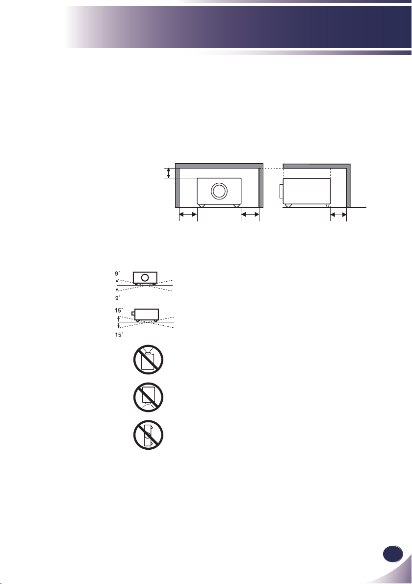
Allowing the proper amount of space on the
top, sides, and rear of the projector cabinet is
critical for proper air circulation and cooling of
the unit. The dimensions shown here indicate the
minimum space required. If the projector is to be
built into a compartment or similarly enclosed,
these minimum distances must be maintained.
SIDE and TOP REAR
Avoid positioning the projector as described
below when installing.
Do not roll the projector more than 9 degrees
from side to side.
Do not pitch the projector more than 15 degrees
from above and below.
Do not point the projector up to project an image.
Do not point the projector down to project an
image.
Do not put the projector on either side to project
an image.
Page 5

4
English
Usage Notice
Do:
■ Turn off the product before cleaning.
■ Use a soft cloth moistened with mild detergent to clean the
display housing.
■ Disconnect the power plug from AC outlet if the product is not
being used for a long period of time.
Do not:
■ Block the slots and openings on the unit provided for ventila-
tion.
■ Use abrasive cleaners, waxes or solvents to clean the unit.
■ Use under the following conditions:
- Extremely heat, cold or humidity.
- In areas susceptible to excessive dust and dirt.
- Near any appliance generating a strong magnetic eld.
- In direct sunlight.
Page 6

English
5
English
Introduction
Introduction
Product Features
This product is an XGA single chip 0.55” DLP® projector. Outstanding features include:
■ True XGA, 1024 x 768 addressable pixels
■ Single chip DLP® technology
■ NTSC3.58/NTSC4.43/PAL(B/D/G/H/I/M/N)/
SECAM (B/D/G/K/K1/L) and SDTV(480i/576i),
EDTV(480p/576p), HDTV(720p/1080i/1080p) compat-
ible
■ Multi-Auto functions: Auto detection, Auto image and
Auto saving the adjustments
■ Full function remote control
■ User friendly multilingual on screen display
■ Advanced digital keystone correction and high quality
full screen image re-scaling
■ Built-in mono 8-Watt speaker.
■ UXGA, WXGA, SXGA+, SXGA compression and VGA,
SVGA re-sizing
■ Macintosh compatible
Page 7
6
English
Introduction
N
o
t
e
Package Overview
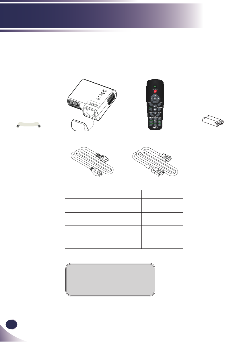
This projector comes with all the items shown below. Check to
make sure your unit is complete. Contact your dealer immediately if anything is missing.
Due to the differ-
ence in applications
for each country, some
regions may have different accessories.
Projector with lens cap
Power Cable VGA Cable
Wireless Remote Control
Cable Factory code
AC Power Cable (for U.S.A.) 42.00105G011
AC Power Cable (for Continental
Europe)
AC Power Cable (for UK) 42.00110G011
VGA Cable 42.00200G005
42.00120G011
Documentation:
CD-ROM User’s Manual
Quick Reference Guide
2 x AAA Batteries
Page 8
English
7
English
Introduction
Product Overview
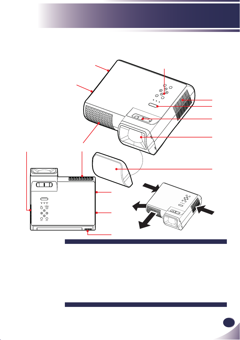
Projector
7
4
1
7
2
3
5
7
4
6
Air Flow
4
7
8
1. Control Panel
2. Remote Sensor
3. Focus Ring
4. Ventilation (outlet)
5. Lens
6. Lens Cap (with String)
7. Ventilation (inlet)
8. Speaker
Page 9
8
English
Introduction
SERVICE
PORT
COMPUTER IN 1
COMPONENT IN 1
(
VARIABLE
)
AUDIO OUT
MONITOR OUT
S-VIDEO IN
VIDEO IN
AUDIO IN
COMPUTER IN 2
COMPONENT IN 2
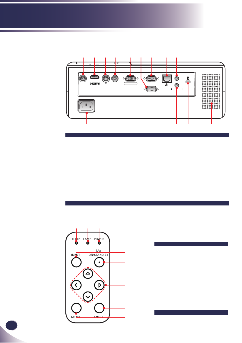
Connection Ports
1 2 3 4 5
10 13
1. SERVICE Port
2. HDMI Port
3. S-VIDEO IN Connector
4. VIDEO IN Connector
5. MONITOR OUT Con-
nector
6. COMPUTER IN 2/
COMPONENT 2 Con-
nector
7 8 9
6
11 12
7. COMPUTER IN 1/
COMPONENT 1 Con-
nector
8. Network Port
9. AUDIO IN Jack
10. AC IN
11. AUDIO OUT Jack
12. KensingtonTM Lock Port
13. Speaker
Control Panel
1 2 3
4
5
1. TEMP LED
2. LAMP LED
3. POWER LED
4. INPUT Button
5. ON/STAND-BY Button
6
6. Four Directional Select
Keys
7. ENTER Button
7
8. MENU Button
8
Page 10
English
9
English
Introduction
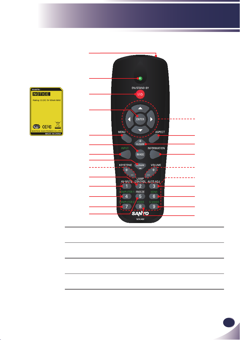
Remote Control
1
2
3
4
15
5
6
7
8
9
10
11
12
13
14
1 Infrared trans-
mitter
2 Infrared indica-
tor
3 ON/STAND-BYRefer to the “Power On/Off the Pro-
4 ENTER Conrm your section of items in sub
Sends signals to the projector.
Signals indicator for sending.
jector” section. (See pages 15~16)
menu operation.
16
17
18
19
20
21
22
23
24
Page 11

10
English
Introduction
N
o
t
e
To quick change
remote control code,
press “MENU” and
“IMAGE” buttons
about 10 seconds at the
same time.
5 MENU Press “MENU” to launch the On-
screen display (OSD), back to the top
level of OSD for the OSD main menu
operation
6 IMAGE Select the Image mode from Presenta-
tion, Movie, sRGB, Bright and User.
7 INPUT Press “INPUT” to choose RGB,
SCART, Component, S-Video, Com-
posite and HDMI sources.
8 D.ZOOM - Zoom out the projector display.
9 KEYSTONE
+/-
10 LAMP CON-
TROL
11 AV-MUTE Momentarily turn off/on the audio
12 COMPUTER 1 Press “COMPUTER 1” to choose
13 COMPUTER 2 Press “COMPUTER 2” to choose
14 FREEZE Pause the screen image. Press again to
15 Four
Directional
Select Keys
16 ASPECT Display the “Aspect Ratio” section of
17 D.ZOOM + Zoom in the projector display.
Adjust the image to compensate for
distortion caused by tilting the projec-
tor.
Select the lamp mode. (refer “ECO
Mode” function)
and video.
Computer in 1/Component in 1 con-
nector.
Computer in 2/Component in 2 con-
nector.
resume the screen image.
Use or or or to select items or
make adjustments to your selection.
the on-screen display menu to select
the desired aspect ratio.
18 INFORMA-
TION
Display information menu.
Page 12

English
11
English
Introduction
19 VOLUME +/- Increase/decrease speaker volume.
20 Keypad 1~9 For input a password in the “Security
settings”.
21 AUTO. ADJ Automatically synchronize the projec-
tor to the input source.
22 HDMI Press “HDMI” to choose HDMI con-
nector.
23 S-VIDEO Press “S-VIDEO” to choose S-Video
connector.
24 VIDEO Press “VIDEO” to choose Video con-
nector.
Page 13
12
English
Introduction
39.4’ (12m)
Approx.30°
N
o
t
e
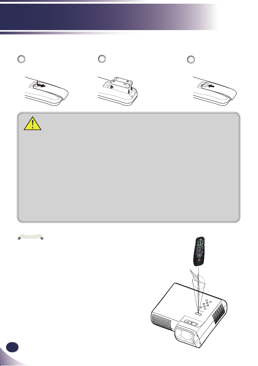
Remote Control Battery Installation
Open the battery com-
1
partment lid.
Install new batteries into the
2
compartment.
Two AAA size batteries
For correct polarity (+
and –), be sure battery
terminals are in contact
with pins in the compartment.
Replace the com-
3
partment lid.
To ensure safe operation, please observe the following precautions :
■ Use two (2) AAA type batteries.
■ Always replace batteries in sets.
■ Do not use a new battery with a used battery.
■ Avoid contact with water or liquid.
■ Do not expose the remote control to moisture or heat.
■ Do not drop the remote control.
■ If the battery has leaked on the remote control, carefully wipe the case clean and
install new batteries.
■ Risk of an explosion if battery is replaced by an incorrect type.
■ Dispose of used batteries according to the instructions.
■ If the new battery are installed into the compartment within 3~4 hours, the remote
control code will not be returned to default.
■ The original setting will be kept and will not be erased.
Remote Control Operating Range
Infrared Remote
Receiver is provided
on the top of the projector.
Point the remote
control from obliquely
above toward the Infrared Remote Receiver
when operating the
remote control.
Point the remote control
toward the projector (Infrared Remote Receiver)
when pressing any button.
Maximum operating range
for the remote control is
about 39.4’ (12m) and 60° in
top of the projector.
Page 14
English
13
English
Installation
SERVICE
PORT
COMPUTER IN 1
COMPONENT IN 1
(
VARIABLE
)
AUDIO OUT
MONITOR OUT
S-VIDEO IN
VIDEO IN
AUDIO IN
COMPUTER IN 2
COMPONENT IN 2
E62405SP
R
N
o
t
e
N
o
t
e
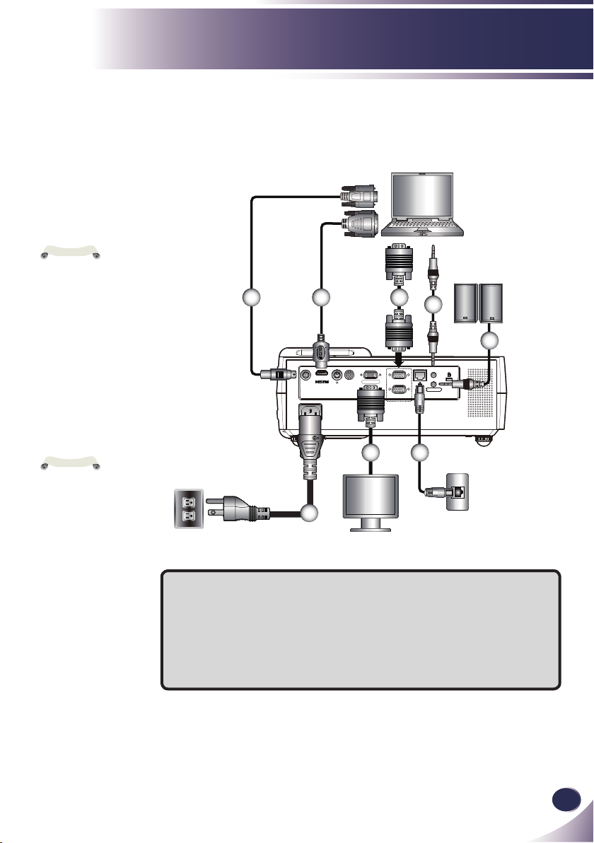
Connecting the Projector
Connect to Computer/Notebook
VGA, DVI
Make sure that the
power plug is fully
inserted into both the
projector AC inlet and
the wall outlet.
The AC outlet must
be near this equipment
and must be easily accessible.
Due to the differ-
ence in applications
for each country, some
regions may have different accessories.
When AUDIO
OUTPUT is plugged-in,
the projector’s build-in
speaker is not available.-
Audio Output
2 43
5
6
8 7
1
Monitor Output
1............................................................................................Power cable (supplied)
2................................................................................................................RS232 cable
3...................................................................................................... HDMI-DVI cable
4.............................................................................................. VGA cable (supplied)
5...................................................................................... Audio in cable jack to jack
6....................................................................................Audio out cable jack to jack
7...........................................................................................................Network cable
8.....................................................................................................Monitor out cable
To ensure the projector works well with your computer,
please make sure the timing of the display mode is
compatible with your projector.
Page 15
14
English
Installation
SERVICE
PORT
COMPUTER IN 1
COMPONENT IN 1
(
VARIABLE
)
AUDIO OUT
MONITOR OUT
S-VIDEO IN
VIDEO IN
AUDIO IN
COMPUTER IN 2
COMPONENT IN 2
E62405SP
R
N
o
t
e
N
o
t
e
Make sure that the
power plug is fully
inserted into both the
projector AC inlet and
the wall outlet.
The AC outlet must
be near this equipment
and must be easily accessible.
Other than the
analog RGB signal,
COMPUTER IN
1/2-COMPONENT IN
1/2 Connectors can
be used to project the
incoming Component
and RGB Scart signals.
(See Page 49 for the
Optional Parts.)
Due to the differ-
ence in applications
for each country, some
regions may have different accessories.
When AUDIO
OUTPUT is plugged-in,
the projector’s build-in
speaker is not available.
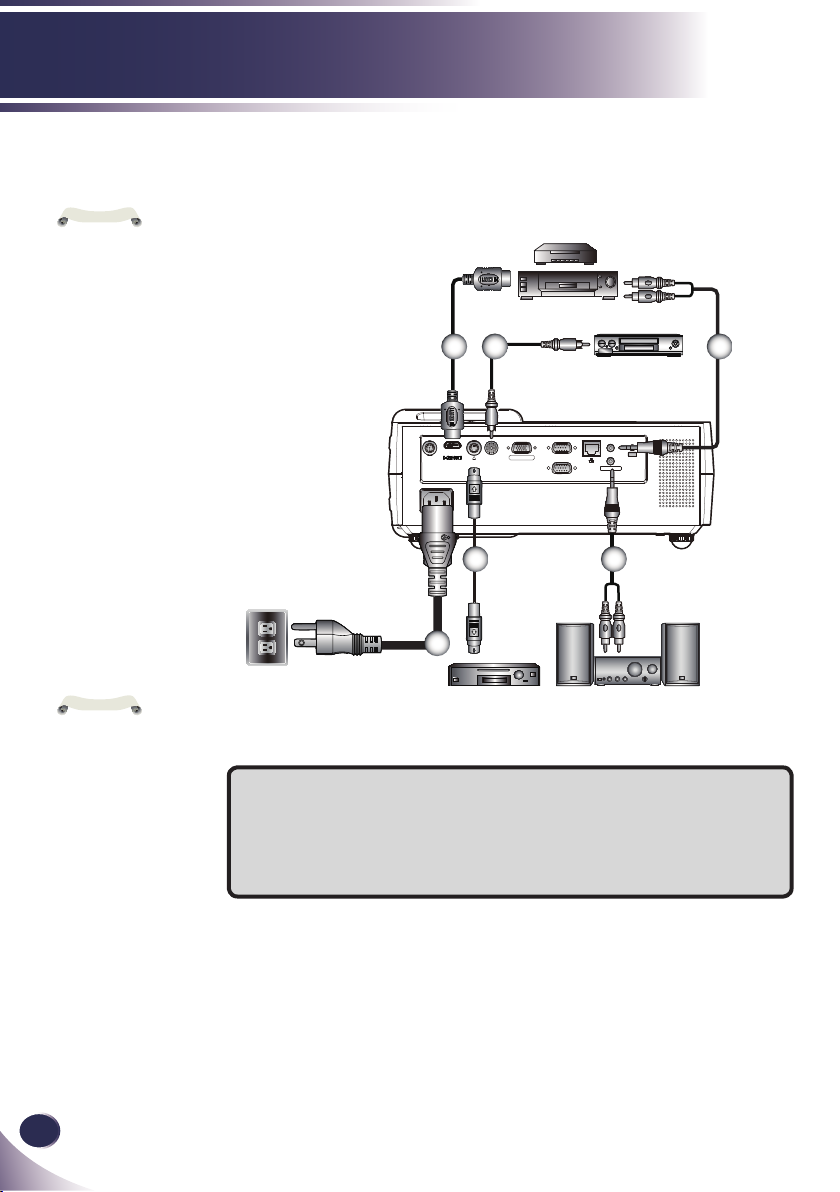
Connect to Video
DVD player, Set-top Box
HDTV receiver
2 43
Video Output
6 5
1
S-Video Output
Audio Output
1............................................................................................Power cable (supplied)
2...............................................................................................................HDMI cable
3............................................................................................ Composite video cable
4...................................................................................... Audio in cable jack to jack
5....................................................................................Audio out cable jack to jack
6............................................................................................................ S-Video cable
To ensure the projector works well with your computer,
please make sure the timing of the display mode is
compatible with your projector.
Page 16
English
15
English
Installation
N
o
t
e
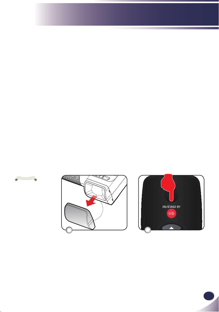
Powering On/Off the Projector
Powering On the Projector
1. Ensure that the power cable and signal cable are securely
connected. The POWER LED will turn orange.
2. Remove the lens cap.
3. Turn on the lamp by pressing “ON/STAND-BY” on the
control panel. The POWER LED will now ash green.
The startup screen will display in approximately 5 seconds.
When disappear startup screen, the POWER LED will turn
green.
4. Turn on your source (computer, notebook, video player,
etc.) The projector will detect your source automatically.
If you connect multiple sources at the same time, use the
“INPUT” on the remote control or use “COMPUTER 1”,
“COMPUTER 2”, “S-VIDEO”, “VIDEO”, “HDMI” on the
remote control to switch inputs.
Turn on the projector
rst and then the signal
sources.
1
Lens Cap Power
2
Page 17

16
English
Installation
Powering Off the Projector
1. Press the “ON/STAND-BY” to turn off the projector lamp,
you will see a message as below on the on-screen display.
2. Press the “ON/STAND-BY” again to conrm.
3. The cooling fan continues to operate for about 60 seconds for
cooling cycle and the POWER LED will ash green. When
the light starts ashing orange, the projector has entered
standby mode.
If you wish to turn the projector back on, you must wait
until the projector has completed the cooling cycle and has
entered standby mode. Once in standby mode, simply press
“ON/STAND-BY” to restart the projector.
4. Disconnect the power cable from the electrical outlet and the
projector.
5. Do not turn on the projector immediately following a power
off procedure.
Page 18
English
17
English
Installation
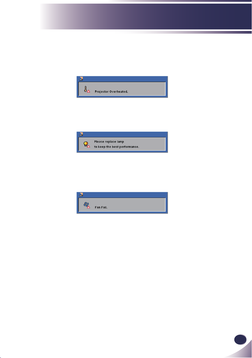
Warning Indicator
When the “TEMP” LED indicator turns red, it indicates the
projector has overheated. The projector will automatically
shut itself down.
When you see the message below displays on-screen, the
projector has detected that the lamp is approaching its end
of life. Please change the lamp as soon as possible or contact
your local dealer or our service center.
When the “TEMP” LED indicator ashes red and the mes-
sage below displays on-screen, it indicates the fan failed.
Stop using the projector and disconnect the power cable
from the electrical outlet, then contact your local dealer or
our service center.
Page 19
18
English
Installation
N
o
t
e
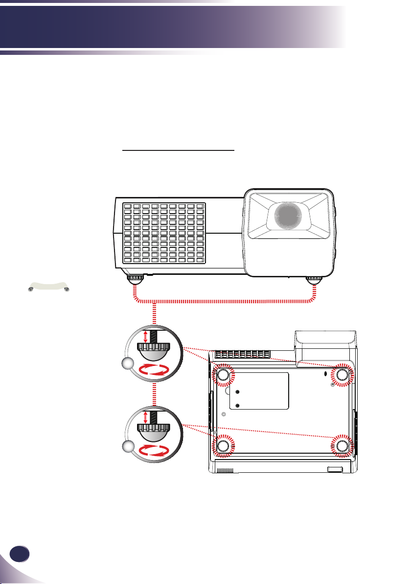
You can raise the
projector front up to 3
degrees by rotating the
adjustable feet.
Adjusting the Projected Image
Adjusting the Height of Projector Image
The projector is equipped with adjustable feet to raise and lower
the image to ll the screen.
To raise/lower the image:
1. Use to ne-tune the display angle.
Front Adjustable feet
Maximun Length:7mm
Rear Adjustable feet
Maximun Length:2mm
1
1
Page 20

English
19
English
Installation
Diagonal
Focus Ring
Adjusting the Projector Focus
To focus the image, rotate the focus ring until the image is clear.
The projector will focus at distances from 1.62 to 12.46 feet (0.5
to 3.8 meters) with mechanical travel.
Adjusting Projection Image Size
This graph is for user’s reference only.
Screen (Diagonal)
40” (101.6cm) 100” (254.0cm) 110” (279.4cm)
Screen Size (WxH)
cm
32.0” x 24.0”
(81.3 x 61.0cm)
80.0” x 60.0”
(203.2 x 152.4cm)
88.0” x 66.0”
(223.5 x 167.6cm)
Distance
1.624’ (0.495m) 4.060’ (1.237m) 4.466’ (1.361m)
H : A = 6.78
H
B ÷ H x 100% = 115%(Offset)
B
A
Lens Center
1.624'
(0.495m)
4.060'
(1.237m)
4.466'
(1.361m)
40"
(101.6cm)
100"
(254.0cm)
Lens Center
110"
(279.4cm)
Page 21

20
English
User Controls
N
o
t
e
On Screen Display
The Projector has a multilingual On Screen Display that allows
you to make image adjustments and change a variety of set-
tings. The projector will automatically detect the source.
How to operate
1. To open the OSD, press “MENU” on the Remote Control.
2. When OSD is displayed, use keys to select any item in the
main menu. While making a selection on a particular page, press
key to enter sub menu.
3. Use keys to select the desired item in the sub menu and
adjust the settings by key.
4. If the setting has icon, you could press “ENTER” to enter an-
other sub menu. Press “MENU” to close the sub menu after adjust-
ment.
5. After adjusting the settings, press “MENU” go back to the main
menu.
6. To exit, press “MENU” again. The OSD will be closed and the pro-
jector will automatically save the new settings.
If no button operation
is made for 30 seconds,
the OSD will be closed
automatically.
Main Menu
Sub Menu Setting
Page 22

English
21
English
User Controls
When no signal is
N
o
t
e
detected, the “Image” menu cannot be
selected.
The image Mode will
change into “User” by
adjusting the items.
Image (PC Mode)
Image Mode
There are many factory presets optimized for various types of im-
ages. Use the or to select the item.
Presentation: For computer or notebook.
Movie: For home theater.
sRGB: For standard color.
Bright: For bright room.
User: Memorize user’s settings.
Brightness
Adjust the brightness of the image.
Press the to darken image.
Press the to lighten the image.
Contrast
The contrast controls the degree of difference between the lightest
and darkest parts of the picture. Adjusting the contrast changes the
amount of black and white in the image.
Press the to decrease the contrast.
Press the to increase the contrast.
Total Dots
Adjust the number of total dots in one horizontal period. Use the
or to adjust number to match your PC image.
Page 23

22
English
User Controls
Fine Sync
Eliminate icker from the image displayed. Use the or to adjust
the value.
White Peaking
Use the white peaking control to set the white peaking level of
DMD chip. 0 stands for minimal peaking, and 10 stands for maximum peaking. If you prefer a stronger image, adjust towards the
maximum setting. For a smooth and more natural image, adjust
towards the minimum setting.
Color Temp.
Adjust the color temperature. At higher temperature, the screen
looks colder; at lower temperature, the screen looks warmer.
Gamma
This allows you to choose a gamma table that has been ne-tuned to
bring out the best image quality for the input.
Page 24

English
23
English
User Controls
When no signal is
N
o
t
e
detected, the “Image” menu cannot be
selected.
The image Mode will
change into “User” by
adjusting the items.
Image (Video Mode)
Image Mode
There are many factory presets optimized for various types of im-
ages. Use the or to select the item.
Presentation: For computer or notebook.
Movie: For home theater.
sRGB: For standard color.
Bright: For bright room.
User: Memorize user’s settings.
Brightness
Adjust the brightness of the image.
Press the to darken image.
Press the to lighten the image.
Contrast
The contrast controls the degree of difference between the lightest
and darkest parts of the picture. Adjusting the contrast changes the
amount of black and white in the image.
Press the to decrease the contrast.
Press the to increase the contrast.
Color
Adjust a video image from black and white to fully saturated color.
Press the to decrease the amount of color in the image.
Press the to increase the amount of color in the image.
Page 25

24
English
User Controls
Tint
Adjust the color balance of red and green.
Press the to increase the amount of green in the image.
Press the to increase the amount of red in the image.
Sharpness
Adjust the sharpness of the image.
Press the to decrease the sharpness.
Press the to increase the sharpness.
White Peaking
Use the white peaking control to set the white peaking level of
DMD chip. 0 stands for minimal peaking, and 10 stands for maximum peaking. If you prefer a stronger image, adjust towards the
maximum setting. For a smooth and more natural image, adjust
towards the minimum setting.
Color Temp.
Adjust the color temperature. At higher temperature, the screen
looks colder; at lower temperature, the screen looks warmer.
Gamma
This allows you to choose a gamma table that has been ne-tuned to
bring out the best image quality for the input.
Page 26

English
25
English
User Controls
Screen
Keystone
Adjust image distortion caused by tilting projector.
H-position (Horizontal Position)
Press the to move the image left.
Press the to move the image right.
V-position (Vertical Position)
Press the to move the image down.
Press the to move the image up.
Aspect Ratio
Use this function to choose your desired aspect ratio.
This format is for 4:3 input sources not enhanced for Wide-
This format is for 16:9 input sources, like HDTV and DVD en-
This format displays the original image without any scaling.
4:3
screen TV.
16:9
hanced for Widescreen TV.
Native
Page 27

26
English
User Controls
Mounting
Front-Desktop
The factory default setting.
Rear-Desktop
When you select this function, the projector reverses the image
so you can project behind a translucent screen.
Front-Ceiling
When you select this function, the projector turns the image
upside down for ceiling-mounted projection.
When you select this function, the projector reverses and turns
Rear-Ceiling
the image upside down at same time. You can project from behind a translucent screen with ceiling mounted projection.
Page 28

English
27
English
User Controls
Setting
Input Search
When this function is turned “On”, the projector will search for
other signals if the current input signal is lost. When this function is
turned “Off”, it will only search a specied connection port.
Fan Control
Choose “On” to turn on Fan Control mode. Operate the fan at full
speed continuously to allow for proper high altitude cooling of the
projector.
Lamp Life Reminder
Choose this function to show or to hide the lamp end of life warning
message.
ECO Mode
Choose “On” to dim the projector lamp which will lower power
consumption and extend the lamp life. Choose “Off” to return to
normal mode.
BrilliantColor
Choose “On” to provide true, more vibrant colors.
TM
RS232 Mode
RS232: Allow RS232 control of an individual projector.
Network: Allow network LAN via web browser (Internet Ex-
plorer) to control of projector.
Page 29

28
English
User Controls
N
o
t
e
N
o
t
e
Eco Standby Power (<1W)
Please turn this func-
tion “Off ”, if you want
to turn on “Power”
by network during
standby mode.
After keystone
adjustment, maybe
need to re-adjust screen
again during display
the closed caption.
This function is available when the projector is turned off and in
Stand-by. It is recommended to use Eco under normal condition.
Remote Control
This projector provides two different remote control codes: the
factory-set initial code (Code 1) and the secondary code (Code 2).
This switching function prevents remote control interference when
operating several projectors or video equipment at the same time.
When operating the projector in “Code 2”, both the projector and
the remote control must be switched to “Code 2”.
■ To change the code for the projector:
Select either “Code 1” or “Code 2” in this Setting Menu.
■ To change the code for the remote control:
Press and hold both the MENU and IMAGE buttons together
Closed Caption
This function is a printed version of the program sound or other
information displayed on the screen. If the input signal contains
closed captions, you can turn on the feature and switch the channels.
Use the or to select Off, CC1, CC2.
Power Management
Set the interval of power-off of the system, if there is no signal input.
(minutes/unit)
Sound
On: lower power consumption than Normal mode in Stand-by
condition.
Off: normal power consumption in Stand-by condition.
for 10 seconds or more. After changing the code, make sure the
remote control operates properly.
Mute:
■ Choose “On” to mute the volume.
■ Choose “Off” to restore the volume.
Page 30

English
29
English
User Controls
Password default
N
o
t
e
value is “1234” (rst
time).
If you input incorrect
password 3 times, the
projector will automatically shut itself down
and enter into standby
mode.
Volume:
■ Press the to decrease the volume.
■ Press the to increase the volume.
Lamp Counter Reset
Reset the lamp life hour after replacing a new lamp.
Security Settings
Security Settings:
■ On: Choose “On” to enable security verication when turning on
the projector.
■ Off: Choose “Off” to be able to switch on the projector without
password verication.
Change Password:
■ First Time:
1. Press “ENTER” to set the password.
2. Use number buttons to enter default password and then press
“ENTER” to conrm.
3. Use number buttons on the remote to enter your new pass-
word and then press “ENTER” to conrm. (The password has
to be 4 digits.)
4. Enter new password again and press “ENTER” to conrm.
■ Change Password:
1. Press “ENTER” to input old password.
2. Use number buttons to enter current password and then press
“ENTER” to conrm.
3. Enter new password (4 digits in length) using the number buttons on the remote, then press “ENTER” to conrm.
4. Enter new password again and press “ENTER” to conrm.
Factory Default
Return the adjustments and settings to the factory default values.
(except for lamp counter, security setting and language)
Page 31

30
English
User Controls
Network Status
Display the network connection status.
DHCP
Display the network connection status.
On: Assign an IP address to the projector from the DHCP server
automatically.
Off: Assign an IP address manually.
IP Address
Select an IP address.
Subnet Mask
Select subnet mask number.
Gateway
Select the default gateway of the network connected to the projector.
DNS
Select DNS number.
Apply
Press “ENTER” button to apply the selection.
Setting/Network
Page 32

English
31
English
User Controls
In the rst instance
N
o
t
e
of powering on the
projector, the language
menu is displayed to
select the default language. All subsequent
operations assume
the selected default
language.
Language
Language
Choose the multilingual OSD. Press into the sub menu and then
use the or or or key to select your preferred
language. Press “ENTER” to nalize the selection.
Information
Information
To display the projector information on the screen.
Page 33

32
English
User Controls
N
o
t
e
N
o
t
e
Controlling the Projector From Web
Conguring the Network Setting
1. Fill in a new IP, a subnet mask, a gateway and a DNS in the
dialogue box.
2. Then choose apply and press “ENTER” button to effectuate the
conguration process.
(1) User name:user /
Password:user
(2) User name: admin-
istrator / Password:
admin
Remark: Only administrator could enter the
Network setting and
alert setting.
3. Open your web browser and type in the IP address, it has entered
LOGIN mode.
4. Input the user name and password then press “LOGIN” button
on the screen, the web page will display as below:
When you used the
projector IP address,
you will can not link to
your service server.
5. Open “Control Panel” to control your projector.
Page 34

English
33
English
User Controls
N
o
t
e
For example: Use Microsoft Internet
Explorer (IE) web browser
to control the projector,
the IP address is http: //
192.168.0.100.
Step 1: Find an IP Address (192.168.0.250)
from LAN function of projector.
Step 2: Select apply and press “ENTER”
button to submit function or press
“MENU” key to exit.
Step 3: To open Network Connections,
Start
click
Network and Internet
click
Connections
Network Connections
connection you want to congure,
and then, under
,
click
connection
Step 4: On the General tab, under This
connection uses the following
items, click Internet Protocol
(TCP/IP), and then click
“Properties.”
Control Panel
, click
, and then click
. Click the
Network Tasks
Change settings of this
.
,
Step 6: To open Internet Options, click
IE web browser, click Internet
Options, click the
and click “LAN Settings...”
Step 7: The
Local Area Network (LAN)
Setting
dialog box appears, In
Proxy Server area
the
Use a proxy server for your LAN
check box
twice.
., then click “OK” button
Connections tab
, cancel the
Step 5: Click
Use the following IP
address
1) IP address: 192.168.0.250
2) Subnet mask: 255.255.255.0
3) Default gateway: 168.0.254.192
, and type in as below:
Step 8: Open your IE and type in the IP
address of 192.168.0.250 in the
URL then press “ENTER” key.
It has entered LOGIN mode as
below:
1) User name: user / Password: user
2) User name: administrator /
Password: admin
Only administrator could enter the
Network setting and alert setting.
Page 35

34
English
User Controls
Step 9: The web page will display as below:
Step 10: Open “Control Panel” to control
your projector.
Page 36

English
35
English
User Controls
When Home page
N
o
t
e
display error status,
it indicates the lamp
failed. Stop using
the projector and
disconnect the power
cable from the electrical
outlet, then contact
your local dealer or our
service center.
Home Page
Access the Projector Web Server by entering the projector’s IP address
at the web browser. The Home Page displays basic information about
the projector.
Page 37

36
English
User Controls
N
o
t
e
N
o
t
e
Control Panel Page
This page allows you to manage the projector status using a Web
browser.
How to operate Control Panel page
Button setting: Action.
The value in the text
box indicates current
value.
Each item has a valid
setting range. The setting value exceeding
this becomes invalid.
Some control items can
not be used depending
on the selecting input
mode or functions of
the projector you use.
In this case, the values
of those items are indicated with “---”.
Text box setting: Enter a number or text and then click “Set” but-
ton. Or Change a value with “-” or “+” button.
Pull-down menu setting: Select an item with pull-down menu but-
ton and then click “Set” button.
Radio button setting: Select an item by selecting a radio button.
Page 38

English
37
English
User Controls
Network Setting Page
This page allow you to enable or disable DHCP and set network related addresses and names.
Projector Setting
Allows you to dene the group name and projector name of the
projector. (Maximum characters: 12).
Network Setting
Choose DHCP to assign an IP address to the projector from a
DHCP server automatically, or Manual to assign an IP address
manually.
Network function setting, Refer to the “Network” section on page
30 for more information.
Password Setting
This projector provides a security function that allows the admin-
istrator or user to manage usage for the projector. When enabling
password for the rst time, set the password before enabling it.
When the password function is enabled, the administrator or user
password will be required for accessing the Web Server.
New Password: Enter new password.
Conrm Password: Enter password again and submit.
Page 39

38
English
User Controls
Security Setting Page
This page allow you control the projector by using the telnet or PJLink
application installed on your computer.
New Password: Enter new password.
Conrm Password: Enter password again and submit.
Telnet Password Setting
Only a four-digit number is valid for the telnet password.
The default Telnet Password as [0000], which means no password is
set.
When you connect the projector to the network, it is recommended
to set a new password.
If the password has been set on this Security Setting Page, the au-
thentication is required to use the Telnet.
PJLink Password Setting
1 to 32 alphanumeric characters can be used for the password.
The default PJLink Password is vacant, which means no password
is set.
Page 40

English
39
English
User Controls
Alert Setting Page
Email Setting
E-mail Alert: You can set whether to be notied by email (Enable) or
not (Disable).
To/CC/From: You can enter email address of sender (From) and
recipients (To/Cc) to receive notication when an abnormality or
warning occurs.
Subject: You can enter the subject line of the email.
Click the “Email Alert Test” button to test the e-mail alert settings.
SMTP Setting
SMTP server, User name and Password should be provided by
your network administrator or MIS.
Alert Condition
You can select the abnormalities or warnings to be notied by
email. Select items by ticking on check boxes. When any of the alert
conditions occur, an email will be sent to the recipients (To/Cc).
Click the “Submit” button to apply the selection.
Page 41

40
English
User Controls
Logout Page
When you use this page, the projector system will go back Login mode.
Page 42

English
41
English
Appendices
Troubleshooting
If you experience trouble with the projector, refer to the fol-
lowing information. If the problem persists, please contact
your local dealer or service center.
Problem: No image appears on screen
Ensure all the cables and power connections are correctly and
securely connected as described in the “Installation” section.
Ensure the pins of connectors are not crooked or broken.
Check if the projection lamp has been securely installed. Please
refer to the “Replacing the lamp” section.
Make sure you have removed the lens cap and the projector is
switched on.
Ensure that the “AV-MUTE” feature is not turned on.
Problem: Partial, scrolling or incorrectly displayed image
Press “Auto Adj.” on the remote control.
If you are using a PC:
For Windows 95, 98, 2000, XP:
1. From the “My Computer” icon, open the “Control Panel” folder,
and double click the “Display” icon.
2. Select the “Settings” tab
3. Click on the “Advanced Properties”.
For Windows Vista:
1. From the “My Computer” icon, open the “Control Panel” folder,
and double click the “Appearance and Personalization”
2. Select “Personalization”
3. Click “Adjust screen resolution” to display “Display Settings”.
Click on the “Advanced Settings”.
If the projector is still not projecting the whole image, you will
also need to change the monitor display you are using. Refer to
the following steps.
Page 43

42
English
Appendices
4. Verify the resolution setting is less than or equal to 1600 x 1200
resolution.
5. Select the “Change” under the “Monitor” tab .
6. Click on “Show all devices”. Next, select “Standard monitor
types” under the SP box; choose the resolution mode you need
under the “Models” box.
If you are using a Notebook:
1. First, follow the steps above to adjust resolution of the com-
puter.
2. Press the toggle output settings. example: [Fn]+[F4]
Compaq=> [Fn]+[F4]
Dell => [Fn]+[F8]
Gateway=> [Fn]+[F4]
IBM=> [Fn]+[F7]
Macintosh Apple:
System Preference-->Display-->Arrangement-->Mirror
display
If you experience difculty changing resolutions or your monitor
freezes, restart all equipment including the projector.
Hewlett
Packard
NEC=> [Fn]+[F3]
Toshiba => [Fn]+[F5]
=> [Fn]+[F4]
Problem: The screen of the Notebook or PowerBook computer is not displaying a presentation
If you are using a Notebook PC:
Some Notebook PCs may deactivate their own screens when a
second display device is in use. Each has a different way to be
reactivated. Refer to your computer’s documentation for detailed
information.
Problem: Image is unstable or ickering
Adjust the “Fine sync” or “Total Dots” to correct it. Refer to the
“Image” section for more information.
Change the monitor color setting from your computer.
Page 44

English
43
English
Appendices
Check and recongure the display mode of your graphic card to
make it compatible with the product.
Problem: Image is out of focus
Adjust the Focus Ring on the projector lens.
Make sure the projection screen is between the required distance
1.62 to 12.46 feet (0.5 to 3.8 meters) from the projector (refer to
page 19).
Problem: The image is stretched when displaying 16:9 DVD
The projector automatically detects 16:9 DVD and adjusts the aspect
ratio by digitizing to full screen with 4:3 default setting.
If the image is still stretched, you will also need to adjust the aspect
ratio by referring to the following:
Please select 4:3 aspect ratio type on your DVD player if you are
playing a 16:9 DVD.
If you can’t select 4:3 aspect ratio type on your DVD player,
please select 4:3 aspect ratio in the on screen menu.
Problem: Image is reversed
Select “Setting-->Mounting” from the OSD and adjust the projec-
tion direction.
Problem: Lamp burns out or makes a popping sound
When the lamp reaches its end of life, it will burn out and may
make a loud popping sound. If this happens, the projector will
not turn on until the lamp module has been replaced. To replace
the lamp, follow the procedures in the “Replacing the Lamp”.
Page 45

44
English
Appendices
N
o
t
e
Problem: LED lighting message
Message
Standby (Input power cable)
Normal (Power on)
Powering up (Warming up) Flashing
Power off (Cooling-I: It can’t accept any
key at this status)
Power off (Cooling-II: It can accept
power key to turn on the projector)
Error (Lamp failed)
Error (Fan lock) Flashing
Error (Over temp.)
POWER-LED
(Red) (Green) (Orange) (Red) (Red)
Flashing
Flashing
TEMP-
LED
LAMP-
LED
*
Steady light =>
No light =>
*=> When LED light
on after 5 sec., go to
standby mode.
Page 46

English
45
English
Appendices
Problem: Message Reminders
Over temperature - the projector has exceeded its recommended
operating temperature and must be allowed to cool down before it
may be used.
Replacing the lamp - the lamp is about to reach its maximum life-
time. Prepare to replace it soon.
Fan failed - the system fan is not working.
Setting network
Loading network
Page 47

46
English
Appendices
Replacing the lamp
The projector will detect the lamp life itself. It will show you a
warning message
Warning: To avoid
burns, allow the
projector to cool for
at least 60 minutes
before you replace the
lamp!
Warning: To reduce the
risk of personal injury,
do not drop the lamp
module or touch the
lamp bulb. The bulb
may shatter and cause
injury if it is dropped.
Warning: For continued safety replace with
a lamp of the same
type.
When you see this message, change the lamp as soon as possible. Make sure the projector has been cooled down for at
least 60 minutes before changing the lamp.
1
2
3
4
Lamp Replacing Procedure:
1. Switch off the power to the projector by pressing the “ON/
STAND-BY”.
2. Allow the projector to cool down at least 60 minutes.
3. Disconnect the power cable.
4. Use a screwdriver to remove the 2 screws from the cover.
5. Push up and remove the cover.
6. Remove the 2 screws from the lamp module and pull up
the lamp bar.
7. Pull out the lamp module by force.
8. Install the new lamp module by reversing the previous steps.
9. After replacing the lamp, turn on the power, and select the
menu ->[Setting] ->[Lamp Counter Reset] to reset the lamp
usage hours. See page 29.
Page 48

English
47
English
Appendices
ORDER REPLACEMENT LAMP
Replacement lamp can be ordered through your dealer. When ordering a
projection lamp, give the following information to the dealer.
■ Model No. of your projector : PDG-DXL100
■ Replacement Lamp Type No. : POA-LMP138
(Service Parts No. 610 346 4633)
LAMP HANDLING PRECAUTIONS
This projector uses a high-pressure lamp which must be handled carefully and
properly.
Improper handling may result in accidents, injury, or create a re hazard.
■ Lamp life may differ from lamp to lamp and according to the environment of
use. There is no guarantee of the same life for each lamp. Some lamps may fail or
terminate their life in a shorter period of time than other similar lamps.
■ If the projector indicates that the lamp should be replaced, i.e., if the lamp life
warning message appears, replace the lamp with a new one IMMEDIATELY after
the projector has cooled down. (Follow carefully the instructions in the Lamp Replacement section of this manual.) Continuous use of the lamp with showing the
lamp life warning message may increase the risk of lamp explosion.
■ A Lamp may explode as a result of vibration, shock or degradation as a result of
hours of use as its lifetime draws to an end. Risk of explosion may differ according
to the environment or conditions in which the projector and lamp are being used.
IF A LAMP EXPLODES, THE FOLLOWING SAFETY PRECAUTIONS
SHOULD BE TAKEN.
If a lamp explodes, disconnect the projector’s AC plug from the AC outlet immediately. Contact an authorized service station for a checkup of the unit and replacement of the lamp. Additionally, check carefully to ensure that there are no broken
shards or pieces of glass around the projector or coming out from the cooling air
circulation holes. Any broken shards found should be cleaned up carefully. No one
should check the inside of the projector except those who are authorized trained
technicians and who are familiar with projector service. Inappropriate attempts to
service the unit by anyone, especially those who are not appropriately trained to do
so, may result in an accident or injury caused by pieces of broken glass.
Page 49

48
English
Appendices
Do not operate the pro-
jector with the air lters
removed. Dust may
accumulate on the optical elements degrading
picture quality.
Do not put anything
into the air intake
vent. It may result in
malfunction of the
projector.
Cleaning the Air Filters
Air lters prevent dust from accumulating on the optical
elements inside the projector. Should the air lters become
clogged with dust particles, it will reduce cooling fans’ effec-
tiveness and may result in internal heat build up and adverse-
ly affect the life of the projector. Clean the air lters following
the steps below.
Air Filters Cleaning Procedure:
1. Turn off the projector, and disconnect the AC power cord
from the AC outlet.
2. Remove the air lters by pulling the latch.
3. Clean the air lters with a brush or rinse them softly.
4. When cleaning the air lters by rinsing, dry them well. Replace the air lters properly. Make sure that the air lters is
fully inserted.
RECOMMENDATION:
■ We recommend avoiding dusty/smoky environments when
operating the projector. Usage in these environments may
cause a poor image quality.
■ When using the projector under dusty or smoky conditions,
dust may accumulate on a lens or optical elements inside the
projector. This condition may degrade the quality of a projected image.
■ When the symptoms above are noticed, contact your autho-
rized dealer or service station for proper cleaning.
Page 50

English
49
English
Appendices
Specications
Projection System Single Chip DLP® Technology by Texas Instruments
Number of Pixels XGA: 1024 pixels(H) X 768 lines(V), up to UXGA (1600 X 1200) with scaling
Lamp 225W (170W on ECO mode)
Projection Lens F#2.6 f=6.97mm with manual focus
Projection Screen Size
(Diag.)
Projection Distance 1.62 to 12.46 feet (0.5 to 3.8 meters)
Video Compatibility - NTSC-M/NTSC-4.43/PAL-B, D, G, H, I/PAL-M/PAL-N/SECAM
H. Frequency 31.35kHz~79.98kHz horizontal scan
V. Frequency 50Hz~75Hz vertical refresh
Power Supply Universal AC input 100-240V ; Input Frequency 50-60Hz
Power Consumption Normal mode:320W
Input Current 2.5-1.0A (100-240V AC)
I/O Connectors - Power: AC power input socket
Built-in Speaker 8W (monaural)
Weight 8.2lbs / 3.7kgs
Dimensions (W x D x H) 12.1 x 11.5 x 4.7 inches (306.5x 292.2 x 120.5 mm) (Including protrusions)
Environmental - Operating Temperature: 41~95oF (5~ 35oC)
Safety Regulation Safety Regulation: UL/CUL
Optional Parts - COMPONENT-VGA Cable : POA-CA-COMPVGA
technology
40 to 307 inches (1.02 to 7.80 meters) Diagonal
- Component: SDTV(480i/576i), EDTV(480p, 576p), HDTV(720p, 1080i/p)
Standby mode <1 Watt
- Computer Input: 2x 15-pin D-Sub VGA for analog/component and HDTV
signal
- RS232 Input: 1x Mini DIN 8-Pin for RS232 control input
- HDMI Input: 1x 19-Pin HDMI(V1.3) for digital video input
- RJ-45 Input: 1x RJ-45 for network management
- Video Input:
1x Composite video RCA input
1x S-Video input
- Audio Input: 1x Stereo Mini Jack
- Computer Output: 1x 15-pin D-Sub VGA for monitor
- Audio Output: 1x Stereo Mini Jack
12.1 x 9.9 x 4.1 inches (306.5x 252.3 x 105.0 mm) (not including protrusions)
Humidity: 80% maximum (Non-condensing)
- Storage Temperature: -4~140oF (-20~60oC)
Humidity: 80% maximum (Non-condensing)
EMC: CB Report, CE Class B, FCC Class B, C-Tick, KC, CCC
- Serial control cable : POA-MCSRL
- VGA cable (10m) : KA-MC-DB10
- SCART-VGA Cable : POA-CA-SCART
Page 51

50
English
Appendices
N
o
t
e
N
o
t
e
Note: “*” compressed
computer image.
Note: The projector
only support a separate
sync signal. Composite
sync and sync on green
are not supported.
Computer Compatibility (Analog)
(1) Signals from D-sub 15
Modes Resolution
VGA 640 x 480 60 31.50
640 x 480 72 37.90
640 x 480 75 37.50
720 x 400 70 31.50
SVGA 800 x 600 56 35.20
800 x 600 60 37.90
800 x 600 72 48.10
800 x 600 75 46.90
832 x 624 75 49.725
XGA 1024 x 768 60 48.40
1024 x 768 70 56.50
1024 x 768 75 60.00
SXGA *1280 x 1024 60 63.98
*1280 x 1024 75 79.98
WXGA *1280 x 720 60 45.00
*1280 x 800 60 49.702
*1440 x 900 60 55.935
QuadVGA *1280 x 960 60 59.70
SXGA+ *1400 x 1050 60 63.98
UXGA *1600 x 1200 60 75.00
Power Mac G4 640 x 480 66.6 (67) 34.93
800 x 600 60 37.90
1024 x 768 60 48.40
*1152 x 870 75 68.68
PowerBook G4 640 x 480 60 31.35
640 x 480 66.6 (67) 34.93
800 x 600 60 37.90
1024 x 768 60 48.40
1152 x 870 75 68.68
i Mac DV (G3) 1024 x 768 75 60.00
V.Frequency
(Hz)
H.Frequency
(kHz)
Page 52

English
51
English
Appendices
Computer Compatibility (DigitalHDMI)
(1) PC digital signals with HDMI-DVI cable
Modes Resolution
VGA 640 x 480 60 31.50
640 x 480 72 37.90
640 x 480 75 37.50
720 x 400 70 31.50
SVGA 800 x 600 56 35.20
800 x 600 60 37.90
800 x 600 72 48.10
800 x 600 75 46.90
832 x 624 75 49.725
XGA 1024 x 768 60 48.40
1024 x 768 70 56.50
1024 x 768 75 60.00
SXGA *1280 x 1024 60 63.98
*1280 x 1024 75 79.98
WXGA *1280 x 720 60 45.00
*1280 x 800 60 49.702
*1440 x 900 60 55.935
QuadVGA *1280 x 960 60 59.70
SXGA+ *1400 x 1050 60 63.98
UXGA *1600 x 1200 60 75.00
Power Mac G4 640 x 480 66.6 (67) 34.93
800 x 600 60 37.90
1024 x 768 60 48.40
*1152 x 870 75 68.68
PowerBook G4 640 x 480 60 31.35
640 x 480 66.6 (67) 34.93
800 x 600 60 37.90
1024 x 768 60 48.40
1152 x 870 75 68.68
i Mac DV (G3) 1024 x 768 75 60.00
V.Frequency
(Hz)
H.Frequency
(kHz)
Page 53

52
English
Appendices
(2) AV digital signals with HDMI cable
Modes Resolution
480i 1440 x 480 60
480p (NTSC) 640 x 480 60
480p (NTSC) 720 x 480 60
576i (PAL) 1440 x 576 50
576p (PAL) 720 x 576 50
720p (NTSC) 1280 x 720 60
720p (PAL) 1280 x 720 50
1080i (NTSC) 1920 x 1080 60
1080i (PAL) 1920 x 1080 50
1080p (NTSC) 1920 x 1080 60
1080p (PAL) 1920 x 1080 50
V.Frequency
(Hz)
Page 54

English
53
English
Appendices
8 7 6
4 3
2 1
5
5 4 3 2 1
10 9 8 7 6
15 14 13 12 11
Congurations of Terminals
Terminal : Analog RGB (Mini D-sub 15 pin)
1
Red (R/Cr) Input/R Output
2
Green (G/Y) Input/G Output
3
Blue (B/Cb) Input/B Output
4
5
6
7
8
***
Ground (Horiz.sync.)
Ground (Red)
Ground (Green)
Ground (Blue)
9
10
11
12
Horiz. sync. Input / Output (Composite H/V
13
14
15
5V / ***
Ground (Ver. sync.)
ICP download
DDC data / ***
sync. Input)
Vert. sync. Input / Output
DDC clock / ***
Terminal : Mini DIN 8-pin
1 RXD
2 ***
3 ***
GND
4
5 ***
6 TXD
7 ***
8 ***
Page 55

54
English
Appendices
Regulation & Safety Notices
This appendix lists the general notices of your Projector.
FCC notice
This device has been tested and found to comply with the limits
for a Class B digital device pursuant to Part 15 of the FCC rules.
These limits are designed to provide reasonable protection
against harmful interference in a residential installation. This
device generates, uses and can radiate radio frequency energy
and, if not installed and used in accordance with the instructions, may cause harmful interference to radio communications.
However, there is no guarantee that interference will not occur
in a particular installation. If this device does cause harmful
interference to radio or television reception, which can be determined by turning the device off and on, the user is encouraged
to try to correct the interference by one or more of the following
measures:
Reorient or relocate the receiving antenna.
▀■
Increase the separation between the device and receiv-
▀■
er.
Connect the device into an outlet on a circuit different
▀■
from that to which the receiver is connected.
Consult the dealer or an experienced radio/television
▀■
technician for help.
Notice: Shielded cables
All connections to other computing devices must be
made using shielded cables to maintain compliance with
FCC regulations.
Caution
Changes or modications not expressly approved by the
manufacturer could void the user’s authority, which is
granted by the Federal Communications Commission, to
operate this projector.
Page 56

English
55
English
Appendices
Operation conditions
This device complies with Part 15 of the FCC Rules. Operation
is subject to the following two conditions:
1. This device may not cause harmful interference and
2. This device must accept any interference received, in-
cluding interference that may cause undesired operation.
Notice: Canadian users
This Class B digital apparatus complies with Canadian
ICES-003.
Remarque à l’intention des utilisateurs canadiens
Cet appareil numerique de la classe B est conforme a la norme
NMB-003 du Canada.
Declaration of Conformity for EU countries
EMC Directive 2004/108/EC (including amendments)
▀■
Low Voltage Directive 2006/95/EC
▀■
R & TTE Directive 1999/5/EC (if product has RF func-
▀■
tion)
FOR EU USERS
The symbol mark and recycling systems described below apply to EU countries and
do not apply to countries in other areas of the world.
Your product is designed and manufactured with high quality materials and components which can be recycled and/or reused.
The symbol mark means that electrical and electronic equipment, batteries and accumulators, at their end-of-life, should be disposed of separately from your household
waste.
Note:
If a chemical symbol is printed beneath the symbol mark, this chemical symbol
means that the battery or accumulator contains a heavy metal at a certain concentration. This will be indicated as follows: Hg: mercury, Cd: cadmium, Pb: lead
In the European Union there are separate collection systems for used electrical and
electronic equipment, batteries and accumulators.
Please, dispose of them correctly at your local community waste collection/recycling centre.
Please, help us to conserve the environment we live in!
Page 57

56
English
Appendices
N
o
t
e
Serial Control Interface
This projector provides a function to control and monitor the
projector’s operations by using the RS-232C serial port.
Operation
1. Connect a RS-232C serial cross cable to SERVICE PORT on the
projector and serial port on the PC.
2. Launch a communication software provided with PC and setup the
communication condition as follows:
3. Type the command for controlling the projector and then enter the
“Enter” key.
Example
When you want to change the input to Computer 2, Type ‘C’ ‘0’ ‘6’
‘Enter’.
Baud rate : 9600 / 19200 bps
Parity check: : none
Stop bit : 1
Flow control : none
Data bit : 8
• The default of the baud rate is set to 9600 bps. If an error occurs in the com-
munication, change the serial port and the communication speed (baud
rate).
• Enter with ASCII 64-byte capital characters and one-byte characters.
Page 58

English
57
English
Appendices
Functional Execution Command
Format
The command is sent from PC to the projector with the format below;
‘C’ [Command] ‘CR’
Command: two characters (refer to the command table below.
■ The projector decodes the command and returns the ‘ACK’ with
the format below;
‘ACK’ ‘CR’
■ When the projector cannot decode the command, it returns with
format below.
‘?’ ‘CR’ projector and serial port on the PC.
Command Function Command Function
C00
C01
C04
C05
C06
C09
C0A
C0B
C0C
C0D
C0E
C0F
C10
C11
C12
C13
C14
C15
C1C
C1D
POWER ON
POWER OFF
(Immediate POWER OFF)
HDMI
Computer 1
Computer 2
Volume +
Volume -
SOUND MUTE ON
SOUND MUTE OFF
VIDEO MUTE ON
VIDEO MUTE OFF
Aspect 4:3
Aspect 16:9
Image mode Presentation
Image mode Movie
Image mode sRGB
Image mode Bright
Image mode User
MENU ON
MENU OFF
C24
C25
C26
C27
C30
C31
C33
C34
C35
C3A
C3B
C3C
C3D
C3F
C43
C44
C89
C8E
C8F
YPbPr 2
---
Scart
IMAGE(Toggle)
D.zoom +
D.zoom -
Video
S-Video
YPbPr 1
POINTER RIGHT
POINTER LEFT
POINITER UP
POINITER DOWN
ENTER
FREEZE ON
FREEZE OFF
AUTO ADJ.
KEYSTONE +
KEYSTONE -
Page 59

58
English
Appendices
N
o
t
e
Status Read Command
Format
The command is sent from PC to the projector with the format below;
‘CR’ [Command] ‘CR’
Command: one character (refer to the command table below.
■ The projector decodes the command and returns the ‘Character
string’ with the format below;
The tables on pages
56~58 show the typical
command lists for controlling the projector.
Please consult your
local dealer for further
information of other
commands.
Command Function
CR0
CR1
CR3
CR4
CR6
CR7
Status Read
Input Mode Read
Lamp Time Read
Setting Read
Temperature Read
Lamp Mode Read
Projector
Return
00
80
20
10
28
21
81
S1
Projector status
Power ON
Standby mode
Cooling Down
Power Failure
Cooling Down due to Abnormal Temperature
in process
Cooling Down in process after Off due to lamp
failure
Standby after Cooling Down due to lamp
failure
S1 = Temperature at Sensor 1 (˚C)
(ex.) S1 = 12.3˚C
--> The projector displays “12.3
Page 60

English
59
English
Appendices
The telnet 10000 port
N
o
t
e
is used to control the
projector.
Further instructions
about the telnet ap-
plication, please see the
on-line guide on your
computer.
Use of Telnet
You can control the projector by using the telnet application
installed on your computer. Normally, the telnet application
is available on your computer.
Control
(For example, in case of using the telnet application of Windows XP
Professional.)
1. Select Run... submenu from Start menu on the computer. Type
“telnet” onto the Open text area on the displayed window and press
OK button.
2. The telnet application will start and the following window will be
displayed. Type as below to connect the projector.
> open 192.168.1.201 10000 [return]
* Use the IP address assigned to the projector.
3. When communication is established correctly, the word “PASSWORD:” appears on the window. Type the login telnet password
for the projector and then press “Enter” key on the keyboard. If you
do not set up the telnet password, just press “Enter” key. When the
word “Hello” is replied, login has been succeeded.
* The password “1234” is used for the example.
Page 61

60
English
Appendices
N
o
t
e
Enter with ASCII
64-byte capital characters and one-byte
characters.
4. Type the commands, refer to right
table, to control the projector and
then press “Enter” key for termina-
tion. For example, type “C00” which
is a command to turn on the projec-
tor, and press “Enter” key. Confirm
the projector is turning on.
To disconnect the communication,
press “Ctrl” key and “]” key at the
same time, type “close” and then press
“Enter” key on the Keyboard.
> close [return]
The table right shows the typical command lists for controlling this projector
Command list table
Command Function
C00
C01
C09
C0A
C0B
C0C
C0F
C10
C1C
C1D
POWER ON
POWER OFF
(Immediate POWER OFF)
Volume +
Volume -
SOUND MUTE ON
SOUND MUTE OFF
Aspect 4:3
Aspect 16:9
MENU ON
MENU OFF
and please consult your local dealer for
further information of another commands.
PJLink Notice
This projector is compliant with PJLink Standard Class 1 of
JBMIA (Japan Business Machine and Information System
Industries Association). This projector supports all com-
mands dened by PJLink Class 1 and is veried conformance
with PJLink Standard Class 1.
Projector PJLink
Input Input Parameter
Computer 1 RGB 1 11
YPbPr 1 RGB 2 12
SCART RGB 3 13
Computer 2 RGB 4 14
YPbPr 2 RGB 5 15
Video VIDEO 1 21
S-Video VIDEO 2 22
HDMI DIGITAL 1 31
PJLink is a registered trademark of JBMIA and pending trademark in
some countries.
Page 62

English
61
English
Appendices
3° Max.
5.07"/128.92mm
1.52"/38.70mm
11.51"/292.29mm
2.59"/65.70mm
9.93"/252.30mm
12.06"/306.53mm
Lens Center
4.99"/126.70mm
4.06"/103.10mm 4.06"/103.10mm
0.74"/18.80mm
4.75"/120.54mm
2.55"/64.67mm
4.74"/120.54mm
0.47"/11.89mm
4.70"/119.50mm
4.13"/105.00mm
Screw Holes for Ceiling Mount
Screw: M4
Depth: 0.47”/12.0mm
Dimensions
Page 63

KF8A
 Loading...