

Page 1

Any and all SANYO products described or contained herein do not have specifications that can handle
applications that require extremely high levels of reliability, such as life-support systems, aircraft’s
control systems, or other applications whose failure can be reasonably expected to result in serious
physical and/or material damage. Consult with your SANYO representative nearest you before using
any SANYO products described or contained herein in such applications.
SANYO assumes no responsibility for equipment failures that result from using products at values that
exceed, even momentarily, rated values (such as maximum ratings, operating condition ranges,or other
parameters) listed in products specifications of any and all SANYO products described or contained
herein.
Monolithic Linear IC
5-Band Graphic Equalizer
Ordering number:ENN1513D
LA3600
SANYO Electric Co.,Ltd. Semiconductor Company
TOKYO OFFICE Tokyo Bldg., 1-10, 1 Chome, Ueno, Taito-ku, TOKYO, 110-8534 JAPAN
Applications
• Portable component stereos, tape-recorders, radio-cassette
recorders, car stereos.
Features
• On-chip one operational amplifier.
• 5-band graphic equalizer for one channel can be formed
easily by externally connecting capacitors and variable
resistors which fix fo (resonance frequency).
• Series connection of two LA3600’s makes multiband (6
to 10 bands) available.
• Highly stable to capacitive load.
Package Dimensions
unit:mm
3006B-DIP16
[LA3600]
16
1
19.2
9
6.4
7.62
8
3.0
3.65max
3.4
0.25
Specifications
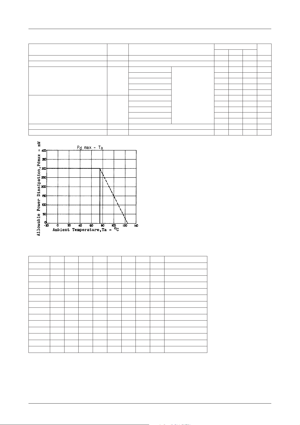
Absolute Maximum Ratings at Ta = 25˚C
retemaraPlobmySsnoitidnoCsgnitaRtinU
egatloVylppuSmumixaMV
noitapissiDrewoPelbawollAxamdP 003Wm
erutarepmeTgnitarepOrpoT 57+ot02–
erutarepmeTegarotSgtsT 521+ot04–
Operating Conditions at Ta = 25˚C
retemaraPlobmySsnoitidnoCsgnitaRtinU
egatloVylppuSdednemmoceRV
egnaRegatloVgnitarepOV
CC
CC
0.71 2.54
xam 02V
CC
po 51ot5V
0.48
1.2
SANYO : DIP16
˚C
˚C
8V
21000TH (KT)/33194HO/7297AT/8225MW/7274KI, TS No.1513–1/7
Page 2
LA3600
Operating Characteristics at Ta = 25˚C, VCC=8V, RL=10kΩ, Rg=600Ω, See specified Test Circuit.
retemaraPlobmySsnoitidnoC
tnerruCtnecseiuQoccI0.30.50.8Am
niaGegatloVGVedomtalfllataBd01–=niV,zHk1=f8.3–8.0+2.2+Bd
zH001=f
zH043=f80121Bd
tnuomAtsooBTSOOB
tnuomAtuCTUC
noitrotsiDcinomraHlatoTDHTV,zHk1=f
egatloVesioNtuptuOV
ON
zHk1=f80121Bd
zHk4.3=f80121Bd
zHk01=f80121Bd
zH001=f21–01–8–Bd
zH043=f21–01–8–Bd
zHk1=f21–01–8–Bd
zHk4.3=f21–01–8–Bd
zHk01=f21–01–8–Bd
V0.1=30.01.0%
o
.zHk1=f
zHk03otzH01.F.P.BtalfllA,0=gR0.202Vµ
sanekatsiBd01–=oV
taedomtalfllataBd0
nimpytxam
80121Bd
sgnitaR
tinU
Test Method : VCC=8V, RL=10kΩ, Rg=600Ω
metI1WS2WS3WS4WS5WS6WS7WS8WSsnoitidnoC
occI 1–––––21
GV 2FFFFF11 Bd01–=niV,zHk1=f
TSOOB 2BFFFF11 zH001=f
TSOOB 2FBFFF11 zH043=f
TSOOB 2FFBFF11 zHk1=f
TSOOB 2FFFBF11 zHk4.3=f
TSOOB 2FFFFB11 zHk01=f
TUC 2CFFFF11 zH001=f
TUC 2FCFFF11 zH043=f
TUC 2FFCFF11 zHk1=f
TUC 2FFFCF11 zHk4.3=f
TUC 2FFFFC11 zHk01=f
DHT 2FFFFF11 V0.1=oV,zHk1=f
V
ON
2FFFFF22
No.1513–2/7
Page 3
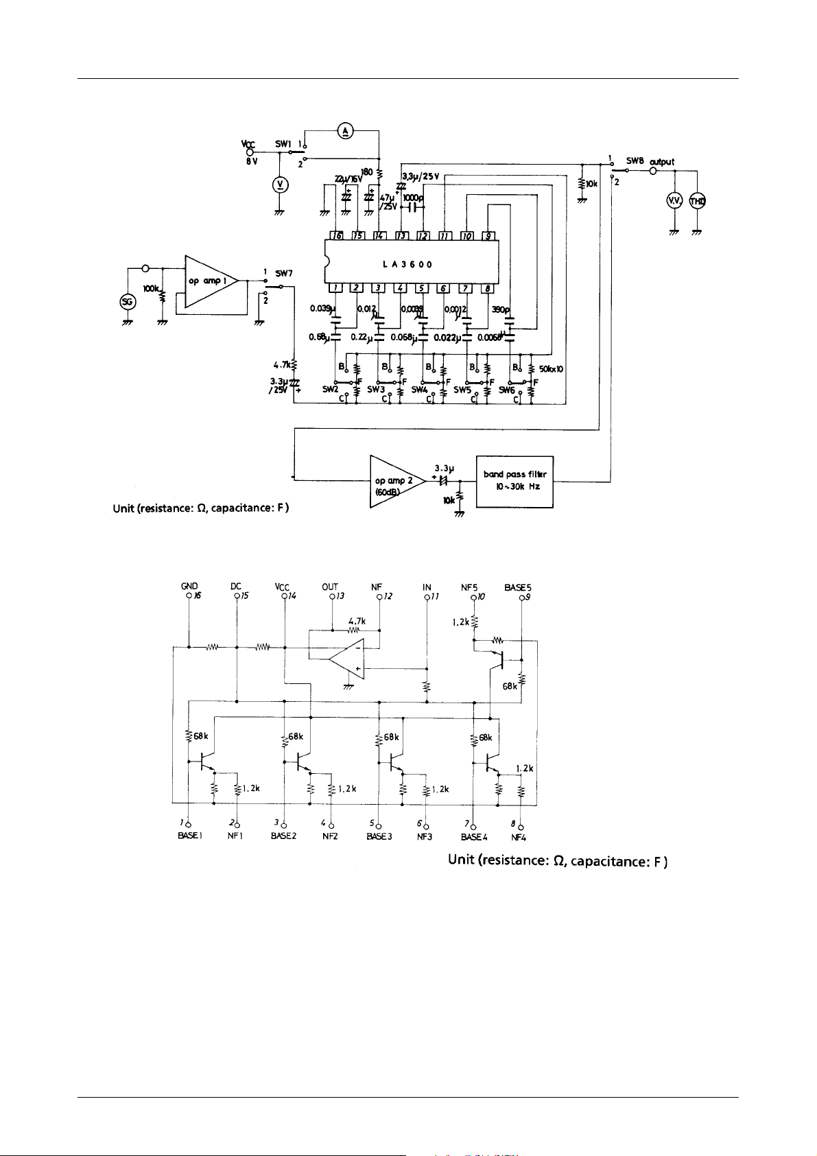
Test Circuit
LA3600
Equivalent Circuit Block Diagram
No.1513–3/7
Page 4

Sample Application Circuit
LA3600
fo (resonance frequency)
In the sample application circuit, fo for each of 5 bands is set as follows :
fo=108Hz, 343kHz, 1.08kHz, 3.43kHz, 10.8kHz
fo= (R1=1.2kΩ, R2=68kΩ on-chip resistor)
2π √ C1, C2, R1, R2
Description of external parts
C1, C2 : Capacitors used to fix fo (resonance frequency)
C2 : Input capacitor. Decreasing the capacitor value lowers the frequency response at low frequencies.
C3 : Input capacitor. Decreasing the capacitor value lowers the frequency response at low frequencies.
C4 : Decoupling capacitor. Decreasing the capacitor value makes the effect of power supply stronger, whereby
ripple is liable to occur.
C5 : Power capacitor.
C6 : Output capacitor. Decreasing the capacitor value lowers the frequency response at low frequencies.
1
No.1513–4/7
Page 5

Sample Printed Circuit Pattern
LA3600
Proper cares in using IC
· Maximum supply voltage VCC max 20V must not be exceeded. The operating voltage is in the range of 5 to 15V.
· Application of power with the pin-to-pin spaces shorted causes breakdown or deterioration of the IC to occur.
When mounting the IC on the board or applying power, make sure that the pin-to-pin spaces are not shorted with
solder, etc.
No.1513–5/7
Page 6

LA3600
No.1513–6/7
Page 7

LA3600
Specifications of any and all SANYO products described or contained herein stipulate the performance,
characteristics, and functions of the described products in the independent state, and are not guarantees
of the performance, characteristics, and functions of the described products as mounted in the customer's
products or equipment. To verify symptoms and states that cannot be evaluated in an independent device,
the customer should always evaluate and test devices mounted in the customer's products or equipment.
SANYO Electric Co., Ltd. strives to supply high-quality high-reliability products. However, any and all
semiconductor products fail with some probability. It is possible that these probabilistic failures could
give rise to accidents or events that could endanger human lives, that could give rise to smoke or fire,
or that could cause damage to other property. When designing equipment, adopt safety measures so
that these kinds of accidents or events cannot occur. Such measures include but are not limited to protective
circuits and error prevention circuits for safe design, redundant design, and structural design.
In the event that any or all SANYO products(including technical data,services) described or
contained herein are controlled under any of applicable local export control laws and regulations,
such products must not be exported without obtaining the export license from the authorities
concerned in accordance with the above law.
No part of this publication may be reproduced or transmitted in any form or by any means, electronic or
mechanical, including photocopying and recording, or any information storage or retrieval system,
or otherwise, without the prior written permission of SANYO Electric Co. , Ltd.
Any and all information described or contained herein are subject to change without notice due to
product/technology improvement, etc. When designing equipment, refer to the "Delivery Specification"
for the SANYO product that you intend to use.
Information (including circuit diagrams and circuit parameters) herein is for example only ; it is not
guaranteed for volume production. SANYO believes information herein is accurate and reliable, but
no guarantees are made or implied regarding its use or any infringements of intellectual property rights
or other rights of third parties.
This catalog provides information as of February, 2000. Specifications and information herein are subject
to change without notice.
PS No.1513–7/7
 Loading...