

SANYO LA1845N Datasheet
Ordering number : ENN7185
91002RM (OT) No. 5888-1/10
Overview
The LA1845N/1845NM is designed for use in mini
systems and is a single-chip tuner IC that provides
electronic tuning functions using SD/IF-count technigue.
It incorporates a pilot canceler and an adjustment-free
MUX VCO circuit, thus allows additional parts to be
reduced.
Functions
• AM: RF amplifier, mixer, oscillator, IF amplifier,
detector, AGC, SD, oscillator buffer, IF buffer,
stereo IF output, AGC time constant switch
• FM IF: IF amplifier, quadrature detector, S-meter, SD
(signal detection), S-curve detection, IF buffer
output
• MPX: PLL stereo decoder, stereo display, forced
monaural, VCO stop, audio muting, adjacent
channel interference rejection function, pilot
canceler
Features
• Integrated MPX VCO (ceramic resonators are no longer
required.)
• Built-in adjacent channel interference rejection function
(114 kHz, 190 kHz)
• Supports both SD and IF-count techniques
• Both FM SD sensitivity and bandwidth can be set
• Pilot canceler built in.
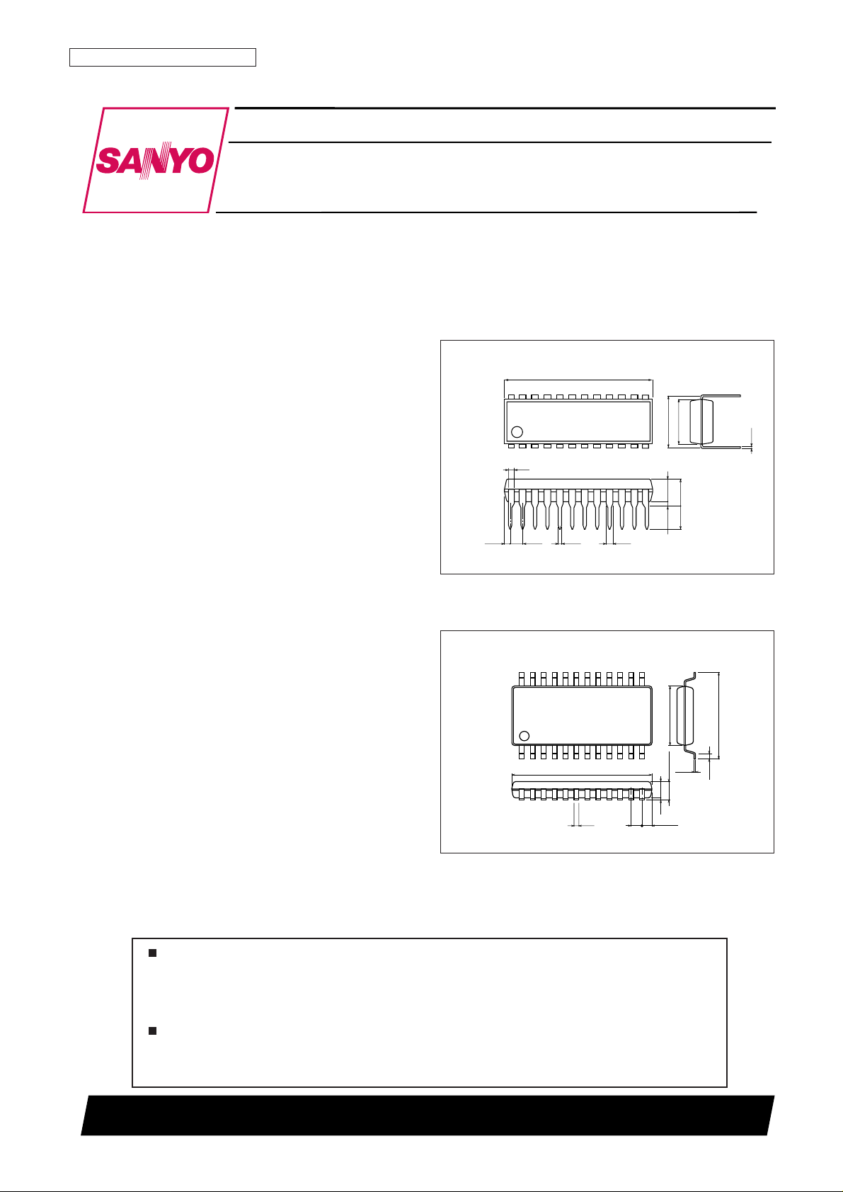
Package Dimensions
unit: mm
3067A-DIP24S
unit: mm
3112A-MFP24S
112
24
13
12.5
(0.75)
1.0
0.15
0.35
5.4
7.6
0.63
1.7max
1.5
0.1
SANYO: MFP24S
[LA1845NM]
0.48
(3.25)
3.3
3.9max
0.51min
21.0
(0.71)
1.78
0.25
7.62
6.4
1
12
24
13
0.95
0.9
SANYO: DIP24S
[LA1845N]
LA1845N, 1845NM
SANYO Electric Co.,Ltd. Semiconductor Company
TOKYO OFFICE Tokyo Bldg., 1-10, 1 Chome, Ueno, Taito-ku, TOKYO, 110-8534 JAPAN
Single-Chip Home Stereo IC
Monolithic linear IC
Any and all SANYO products described or contained herein do not have specifications that can handle
applications that require extremely high levels of reliability, such as life-support systems, aircraft’s
control systems, or other applications whose failure can be reasonably expected to result in serious
physical and/or material damage. Consult with your SANYO representative nearest you before using
any SANYO products described or contained herein in such applications.
SANYO assumes no responsibility for equipment failures that result from using products at values that
exceed, even momentarily, rated values (such as maximum ratings, operating condition ranges, or other
parameters) listed in products specifications of any and all SANYO products described or contained
herein.
Specifications
Maximum Ratings at Ta = 25°C
Operating Conditions at Ta = 25°C
Operating Characteristics at Ta = 25°C, VCC= 8 V, in the specified test circuit.
No. 5888-2/10
LA1845N, 1845NM
Parameter Symbol Conditions Ratings Unit
Maximum supply voltage V
CC
max 9 V
Pd max Ta ≤ 45°C 400 mW
Allowable power dissipation Pd max Ta = 80°C (DIP) 400 mW
Pd max Ta = 80°C (MFP) 260 mw
Operating temperature Topr –20 to +80 °C
Storage temperature Tstg –40 to +125 °C
Parameter Symbol Conditions Ratings Unit
Recommended supply voltage V
CC
8 V
Operating supply voltage range VCCop Ta = 80°C 4.3 to 8.5 V
Parameter Symbol Conditions
Ratings
Unit
min typ max
[FM Mono Characteristics] fc = 10.7 MHz, Vi = 100 dBµ, fm = 1 kHz, Mod = 75 kHz
Current drain I
CCO-FM
With no input signal 20 30 40 mA
Demodulator output V
OFM
100 dBµ, 100% modulation, fm = 1 kHz 230 360 460 mVrms
Total harmonic distortion THD
FM
100 dBµ, 100% modulation, fm = 1 kHz 0.35 1.5 %
Signal-to-noise ratio S/N
FM
100 dBµ, 100% modulation, fm = 1 kHz 73 80 dB
AM rejection ratio AMR 100 dBµ, AM 30% modulation, fm = 1 kHz 47 65 dB
3 dB sensitivity 100 dBµ, 100% modulation, fm = 1 kHz, -3 dB input 32 40 dBµ
SD sensitivity 0% modulation 38 47 56 dBµ
IF counter buffer output V
IFBuff-FM
100 dBµ, the pin 13 output 80 120 160 mVrms
Mute attenuation Mute-Att 100 dBµ, 100% modulation, fm = 1 kHz 75 85 dB
[FM Stereo Characteristics] fc = 10.7 MHz, Vi = 100 dBµ, fm = 1 kHz, L + R = 90%, Pilot = 10%
Separation SepLLeft channel modulated. The pin 16 output/the pin 17 output 30 42 dB
Stereo on level ST
ON
The pilot modulation such that V7 falls under 0.7 V 1.5 3.5 5.5 %
Total harmonic distortion THD-main Left + right modulation. The pin 16 output. 0.45 1.5 %
fs = 113 kHz, Vs = 90%, pilot = 10%
Adjacent channel rejection ratio 1 Brej-3rd
The left - right modulation, demodulated output
36
dB
fs = 189 kHz, Vs = 90%, pilot = 10%
Adjacent channel rejection ratio 2 Brej-5th
The left - right modulation, demodulated output
41
dB
Carrier leak L + R = 90%, pilot = 10% reference, pilot = 10% output 38 44
dB
[AM Characteristics] fc = 1000 kHz, Vi = 80 dBµ, fm = 1 kHz, Mod = 30%
Current drain I
CCO-AM
With no input signal 13 27 39 mA
Detector output 1 V
OAM1
23 dBµ, 30% modulation, fm = 1 kHz 40 80 160 mVrms
Detector output 2 V
OAM2
80 dBµ, 30% modulation, fm = 1 kHz 90 160 230 mVrms
Signal-to-noise ratio 1 S/N
AM1
23 dBµ, 30% modulation, fm = 1 kHz 17 23 dB
Signal-to-noise ratio 2 S/N
AM2
80 dBµ, 30% modulation, fm = 1 kHz 46 52 dB
Total harmonic distortion 1 THD
AM1
80 dBµ, 30% modulation, fm = 1 kHz 0.4 1.1 %
Total harmonic distortion 2 THD
AM2
107 dBµ, 30% modulation, fm = 1 kHz 0.5 1.3 %
SD sensitivity 0% modulation 11 20 29 dBµ
Local oscillator buffer output V
OSC-AM
With no input signal 100 140 200 mVrms
IF counter buffer output V
IFBuff-AM
23 dBµ 140 285 400 mVrms
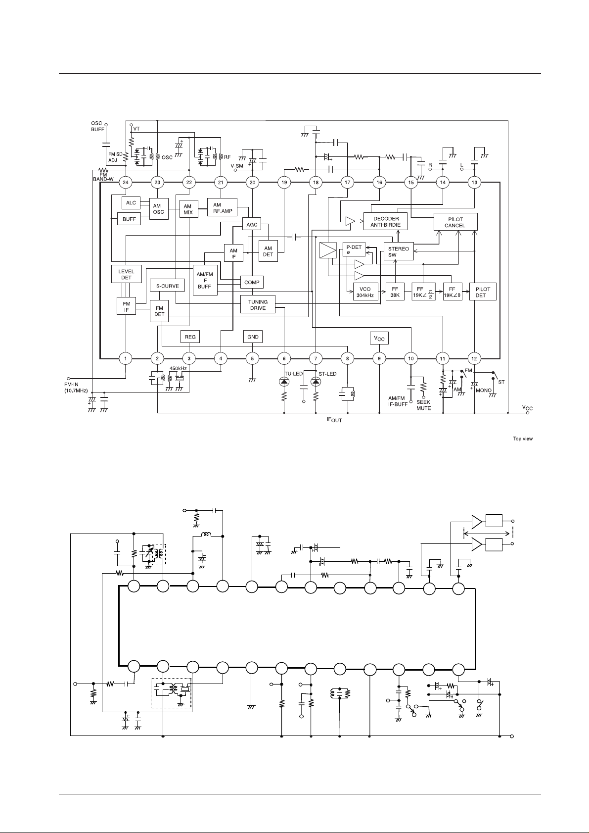
Block Diagram
AC Test Circuit
No. 5888-3/10
LA1845N, 1845NM
(8.0 to 9.0 V)
24 23 22
21
20 19
18
17 16 15
14 13
1 2
3
4 5
6
7 8 9
10 11 12
LA1845N/1845NM
OSC
BUFF
1000pF
6.8kΩ
5.6kΩ
39pF
20pF
AM-IN
(1MHz)
39MH
3.3µF
50Ω
22µ F
0.047µF
20k Ω
10µ F
20k Ω
4.7µF
1000pF
0.1µF
65k Ω
A
LPF
LPF
L
OUT
R
OUT
0dB
0.0047µF
0.015µF
50kΩ
50kΩ
0.01µF
0.047µF
300Ω
75Ω
FM-IN
(10.7MHz)
33µ F 0.047µF
HW6215
V-SD
V-ST
TU-LED
ST-LED
AM IF
10kΩ
FM
AM
SEEK V
CC
8.0V
MONO
1µF
1µF
3kΩ
AM/FM
IF-BUFF
1000pF
HW50425
A
0.047µF
600BEAS-10471
detector coil
Top view
0.015µF
1000pF
20pF
NORMAL
0.47
µF
 Loading...