

Page 1
Ordering number: EN3892B
Monolithic Linear IC
L88R05 Series
5 V, 1 A Voltage-regulator ICs
with Reset Function
Overview
The L88R05 Series is a series of low-saturation voltage
regulator ICs that are equipped with a function that generates a
reset signal when the power supply for a microcontroller
system is turned on or off.
Applications
.
Prevents malfunction when the microcontroller power supply
is turned on or off.
.
Designed to handle malfunction caused by momentary power
interruptions.
.
Suited for portable electronic equipment, mobile electronic
equipment, and other battery-powered equipment with little
capacity to handle fluctuation in input voltage; also suited
for equipment with large fluctuations in the primary power
supply.
Functions
.
Power supply reset generation function; the reset threshold
voltages are ranked.
L88R05C: V
L88R05D: V
L88R05E: V
.
5 V, 1 A output characteristics
RT
RT
RT
= 4.5 V
= 4.2 V
= 3.9 V
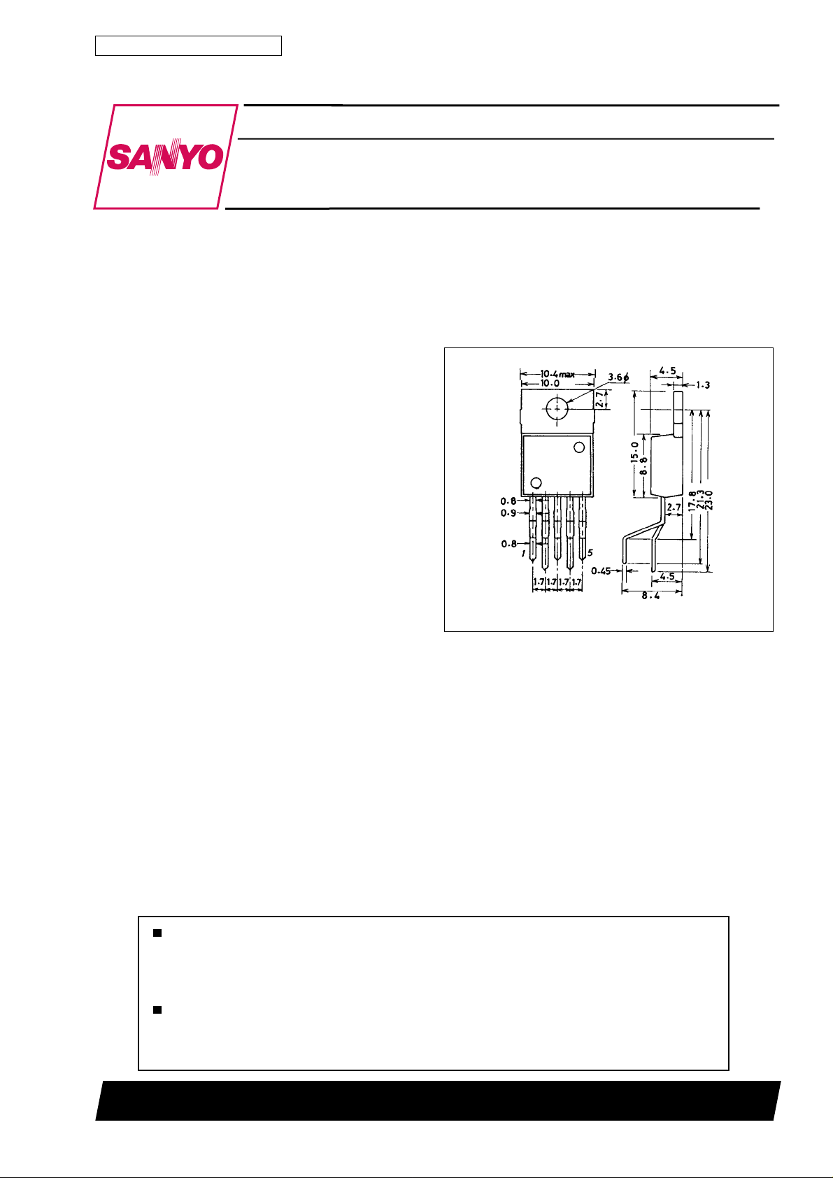
Package Dimensions
unit : mm
3079-T0220-5H
[L88R05 Series]
SANYO : TO220-5H
Features
.
Minimum I/O voltage difference is small (0.5 V typ.), making power conservation possible, and makes smaller heatsink and
transformers possible.
.
External capacitor for reset signal output delay time adjustment.
.
Sink/source reset output provides compatibility with logic circuitry that has an internal pull-down resistor. Active pull-up
facilitates noise suppression.
.
Various types of protective circuits on chip (fold back current limiting, thermal protection).
.
The package is the TO220-5H; this package facilitates designs for the radiation of heat during the mounting process.
Any and all SANYO products described or contained herein do not have specifications that can handle
applications that require extremely high levels of reliability, such as life-support systems, aircraft’s
control systems, or other applications whose failure can be reasonably expected to result in serious
physical and/or material damage. Consult with your SANYO representative nearest you before using
any SANYO products described or contained herein in such applications.
SANYO assumes no responsibility for equipment failures that result from using products at values that
exceed, even momentarily, rated values (such as maximum ratings, operating condition ranges, or other
parameters) listed in products specifications of any and all SANYO products described or contained
herein.
SANYO Electric Co.,Ltd. Semiconductor Bussiness Headquarters
TOKYO OFFICE Tokyo Bldg., 1-10, 1 Chome, Ueno, Taito-ku, TOKYO, 110-8534 JAPAN
O1596HA(II)/5272TS No.3892-1/6
Page 2
L88R05 Series
Specifications
Maximum Ratings at Ta = 25°C
Parameter Symbol Conditions Ratings Unit
Maximum input voltage
Reset pin voltage
Allowable power dissipation Pd max
Junction-to-ambiet thermal
resistance
Junction-to-case thermal
resisitance
Operating temperature Topr –40 to +85 °C
Storge temperature Tstg –55 to +150 °C
V
max
IN
V
max
RES
Ta % 25°C, independent IC 1.75 W
Tc % 50°C, ideal radiation of heat 20 W
Uj-a 71.4 °C/W
Uj-c 5 °C/W
Operating Conditions atTa=25°C
Parament Symbol Conditions Ratings Unit
Input voltage
Output current
Reset output source current
Reset output sink current
V
l
OUT
l
ORH
l
ORL
IN
18 V
18 V
5.6 to 17 V
0to1 A
0 to 200 µA
0to2 mA
Operating Characteristics at Tj = 25 °C, VIN=8V,I
Parameter Symbol Condition min typ max Unit
[Power Supply]
Output voltage V
Dropout voltage
Line regulation ∆V
Load regulation ∆V
Peak output current l
Output short-circuit current l
Current drain
Output noise voltage V
Output voltage temperature
coefficient
Ripple rejection ratio Rrej f = 120 Hz, 6 V % V
[Reset]
High-level reset output voltage V
Low-level reset output voltage V
Reset threshold voltage V
Reset hysteresis voltage V
Output delay time t
OUT
V
DROP1
V
DROP2lOUT
OLN
OLD
OP
OSC
I
Q1
I
Q2
NO
∆Vo/∆Ta Tj =25 to 125 °C –0.5 mV/°C
ORH
ORL
RT
hys
d
= 300 mA 0.25 0.50 V
5.6 V % VIN% 17 V 10 70 mV
5mA%I
I
= 0 2.1 4 mA
OUT
10 Hz % f % 100 kHz 70 µVrms
l
= 200 µA, CD open 4.83 4.98 5.13 V
ORH
l
= 2 mA, CD grounded 100 200 mV
ORL
C-rank 4.3 4.5 4.7 V
D-rank 4.0 4.2 4.4 V
E-rank 3.7 3.9 4.1 V
Cd = 0.1 µF 7.5 10 12.5 ms
% 1 A 50 150 mV
OUT
IN
= 1 A, C
OUT
% 17 V 60 dB
= 47 µA for specified circuits
OUT
4.85 5.0 5.15 V
0.5 1.0 V
1 1.8 A
0.3 1.2 A
32 80 mA
50 100 200 mV
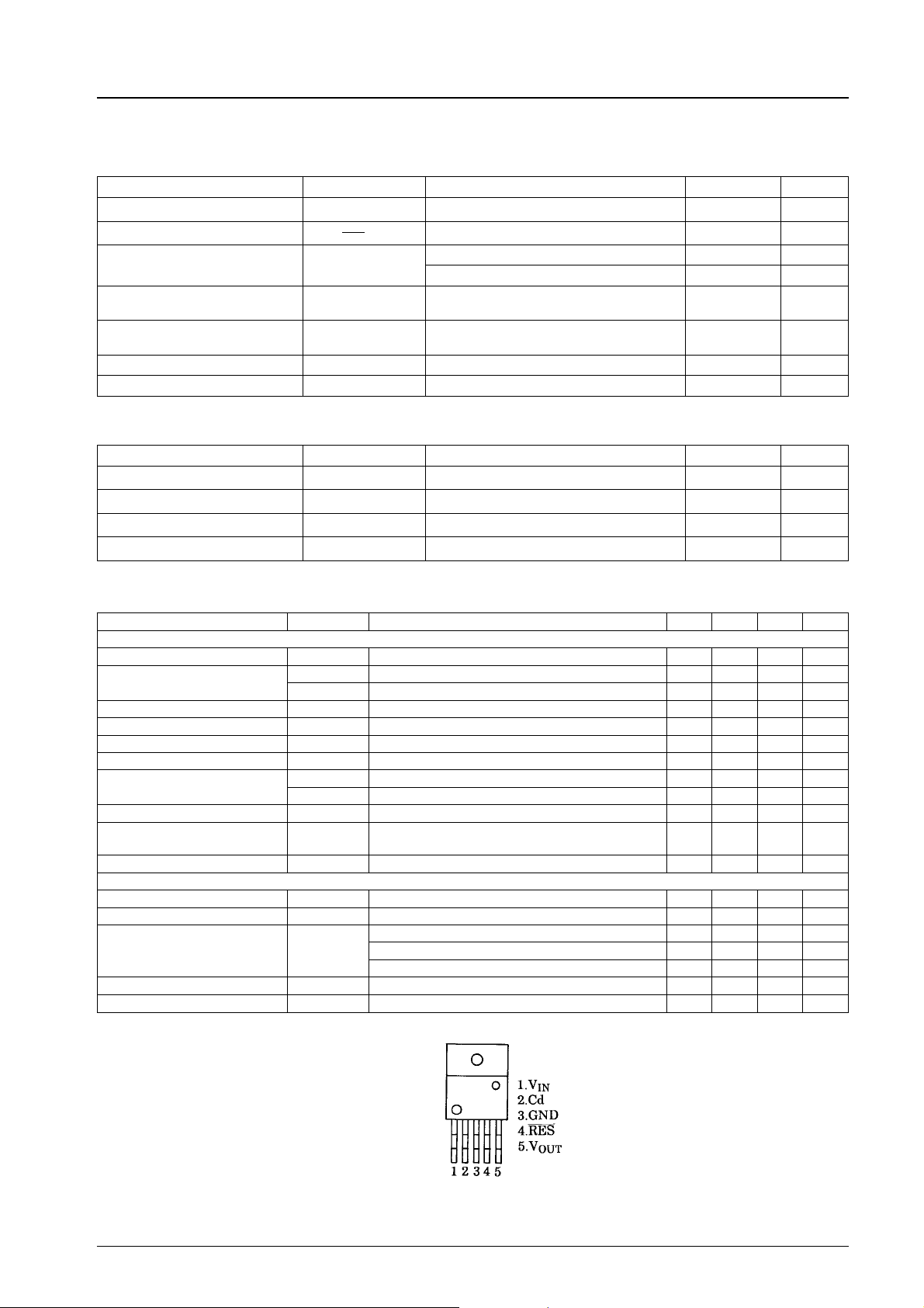
Pin Assignments
Top view
No.3892-2/6
Page 3

Equivalent Circuit Block Diagram
Error
amplifier
Starter circuit
voltage
Reference
L88R05 Series
Thermal
protection
Overcurrent
limiting
Measurement Circuit
Unit (capacitance: F)
No.3892-3/6
Page 4

Sample Application Circuit
Notes:
1. Set C
2. Use the capacitators for C
to be 47 µF or greater and select it according to the applications.
OUT
and Cd with high-temperature stability.
OUT
L88R05 Series
To VDDof peripheral
circuit
Unit (capacitance: F)
L88R05C’s Reset Operation
No.3892-4/6
Page 5

L88R05 Series
–V
O
Output voltage, V
–V
O
VO–I
O
Output current, IO–A
VO–Ta
–V
O
Output voltage, V
–mA
Q
V
O–VIN
Input voltage, VIN–V
I
Q–VIN
Output voltage, V
–mA
Q
Current drain, I
–V
RES
C-type
Ambient temperature, Ta – °C
IQ–I
O
Output current, IO–A
V
RES–VO
Current drain, I
–V
DROP
Dropout voltage, V
–V
RES
D-type
Input voltage, VIN–V
V
DROP–IO
Output current, IO–A
V
RES–VO
Reset voltage, V
Output voltage, VO–V
Reset voltage, V
Output voltage, VO–V
No.3892-5/6
Page 6

L88R05 Series
RES–V
Reset voltage, V
E-type
V
RES–VO
Output voltage, VO–V
Infinite heatsink
100 × 100 × 2mm3Al plate
50 × 50 × 2mm
No heatsink
Allowable power dissipation, Pd max – W
Pd max – Ta
Sillicon grease on heatsink
39 Nvcm mounting torque
θj-c = 5°C/W
θj-a = 71.4°C/W
3
Al plate
Ambient temprature, Ta – °C
Specifications of any and all SANYO products described or contained herein stipulate the performance,
characteristics, and functions of the described products in the independent state, and are not guarantees
of the performance, characteristics, and functions of the described products as mounted in the customer’s
products or equipment. To verify symptoms and states that cannot be evaluated in an independent device,
the customer should always evaluate and test devices mounted in the customer’s products or equipment.
SANYO Electric Co., Ltd. strives to supply high-quality high-reliability products. However, any and all
semiconductor products fail with some probability. It is possible that these probabilistic failures could
give rise to accidents or events that could endanger human lives, that could give rise to smoke or fire,
or that could cause damage to other property. When designing equipment, adopt safety measures so
that these kinds of accidents or events cannot occur. Such measures include but are not limited to protective
circuits and error prevention circuits for safe design, redundant design, and structural design.
In the event that any or all SANYO products(including technical data,services) described or
contained herein are controlled under any of applicable local export control laws and regulations,
such products must not be exported without obtaining the export license from the authorities
concerned in accordance with the above law.
No part of this publication may be reproduced or transmitted in any form or by any means, electronic or
mechanical, including photocopying and recording, or any information storage or retrieval system,
or otherwise, without the prior written permission of SANYO Electric Co. , Ltd.
Any and all information described or contained herein are subject to change without notice due to
product/technology improvement, etc. When designing equipment, refer to the “Delivery Specification”
for the SANYO product that you intend to use.
Information (including circuit diagrams and circuit parameters) herein is for example only ; it is not
guaranteed for volume production. SANYO believes information herein is accurate and reliable, but
no guarantees are made or implied regarding its use or any infringements of intellectual property rights
or other rights of third parties.
This catalog provides information as of October, 1996. Specifications and information herein are subject to
change without notice.
PS No.3892-6/6
 Loading...