

Page 1
INSTRUCTION MANUAL
COOL/DRY Model
Split System Air Conditioner
In order to protect the environment, this air conditioner uses the new refrigerant R410A.
KS2462R
Save These Instructions!
Pub. OI-85464189508000 ©SANYO 2002
Printed on Recycled Paper
Page 2

Features
This air conditioner is equipped with cooling and drying functions. Details on these functions are provided
below; refer to these descriptions when using the air conditioner.
•
Microprocessor Controlled Operation
The interior compartment of the remote control
unit contains several features to facilitate
automatic operation, each logically displayed for
easy use.
•
Simple One-touch Wireless Remote Control
The remote control unit has several features to
facilitate automatic operation.
•
24-HourONorOFFTimer
This timer can be set to automatically turn the
unitonoroffatanytimewithina24 hour
period.
•
1-Hour OFF Timer
This timer can be set to automatically turn off
the unit at any time after one hour.
•
Night Setback
Pressing this button changes the setting of the
room temperature thermostat, allowing you to
set the temperature at whatever level that you
find comfortable.
•
Air Sweep Control
This function moves a flap up and down in the
air outlet, directing air in a sweeping motion
around the room and providing comfort in every
corner.
•
Automatic Restart Function for Power Failure
Even when power failure occurs, preset programmed operation can be reactivated once
power resumes.
•
Anti-Mold Filter
This unit is equipped with an anti-mold filter
that inhibits the growth of mold and bacteria.
•
Optional Air Clean Filter
An air filter that uses activated charcoal to
eliminate unpleasant odors and clean the air is
available (sold separately).
•
Automatic and 3-step Fan Speed
Auto/High/Medium/Low
2OI-508-02EG
Page 3
Contents
Page
Features.................................................................................................................. 2
Product Information .............................................................................................. 3
Alert Symbols ........................................................................................................ 3
Installation Location.............................................................................................. 4
Electrical Requirements ........................................................................................ 4
Safety Instructions ................................................................................................ 4
Names of Parts ...................................................................................................... 5
Using the Remote Control Unit ......................................................................... 10
Operation with the Remote Control Unit.......................................................... 12
1. Manual Operation ................................................................................. 12
2. Adjusting the Fan Speed...................................................................... 13
3. Night Setback Mode ............................................................................ 14
Special Remarks ................................................................................................. 15
Setting the Timer.................................................................................................16
Setting the1-HourOFFTimer............................................................................18
AdjustingtheAirflowDirection.........................................................................19
OperationwithouttheRemoteControlUnit....................................................20
CareandCleaning...............................................................................................20
TipsforEnergySaving......................................................................................23
Troubleshooting...................................................................................................24
OperatingRange.................................................................................................24
Product Information
If you have problems or questions concerning your Air Conditioner, you will
need the following information. Model and serial numbers are on the
nameplate on the bottom of the cabinet.
Model No.
Date of purchase
Dealer’s address
Serial No.
Phone number
Alert Symbols
The following symbols used in this manual, alert you to potentially
dangerous conditions to users, service personnel or the appliance:
This symbol refers to a hazard or unsafe
practice which can result in severe personal
injury or death.
CAUTION
This symbol refers to a hazard or unsafe
practice which can result in personal injury
or product or property damage.
3OI-508-03EG
Page 4
Installation Location
•
We recommend that this air conditioner be installed properly by
qualified installation technicians in accordance with the Installation
Instructions provided with the unit.
•
Before installation, check that the voltage of the electric supply in your
home or office is the same as the voltage shown on the nameplate.
•
Do not install this air conditioner where there are fumes or flammable
gases, or in an extremely humid space such as a greenhouse.
•
Do not install the air conditioner where excessively high heatgenerating objects are placed.
Avoid: To protect the air conditioner from heavy corrosion, avoid installing the
outdoor unit where salty sea water can splash directly onto it or in
sulphurous air near a spa.
Electrical Requirements
1. All wiring must conform to the local electrical codes. Consult your
dealer or a qualified electrician for details.
2. Each unit must be properly grounded with a ground (or earth) wire or
through the supply wiring.
3. Wiring must be done by a qualified electrician.
CAUTION
Safety Instructions
•
Read this Instruction Manual carefully before using this air conditioner.
If you still have any difficulties or problems, consult your dealer for
help.
•
This air conditioner is designed to give you comfortable room
conditions. Use this only for its intended purpose as described in this
Instruction Manual.
•
Never use or store gasoline or other flammable vapor or liquid near
the air conditioner — it is very dangerous.
•
This air conditioner has no ventilator for intaking fresh air from
outdoors. You must open doors or windows frequently when you use
gas or oil heating appliances in the same room, which
consume a lot of oxygen from the air. Otherwise there is a risk of
suffocation in an extreme case.
•
Do not turn the air conditioner on and off from the power mains
switch. Use the ON/OFF operation button.
•
Do not stick anything into the air outlet of the outdoor unit. This is
dangerous because the fan is rotating at high speed.
•
Do not let children play with the air conditioner.
•
Do not cool the room too much if babies or invalids are present.
4OI-508-04EG
Page 5
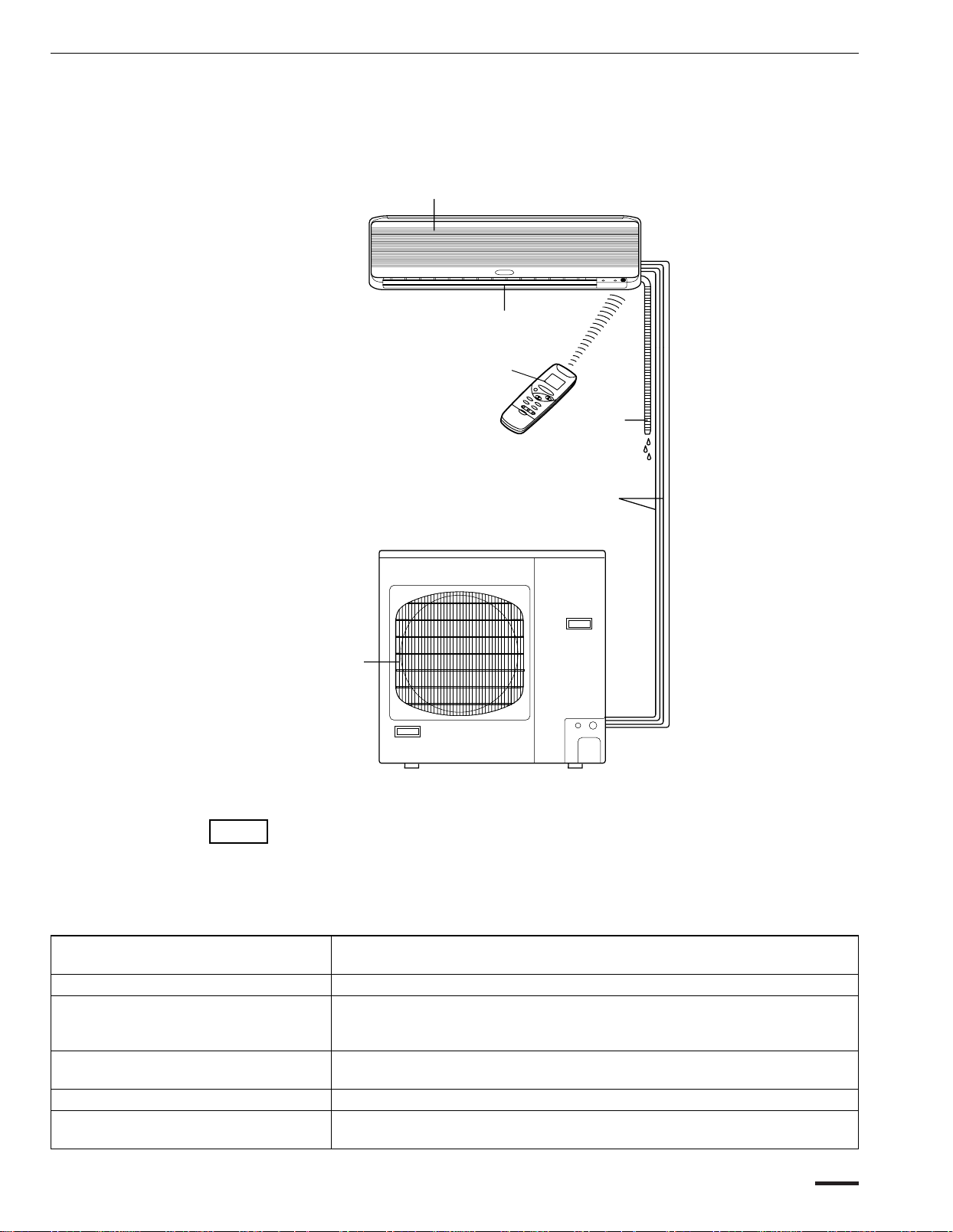
Names of Parts
INDOOR UNIT
Air intakes
Air outlet
Remote
control
unit
OUTDOOR UNIT
Drain
hose
Refrigerant
tubes
Air outlet
NOTE
Air Intakes Air from the room is drawn into these sections and passes through
Air Outlet Air is blown out of the air conditioner through the air outlet.
Remote Control Unit The wireless remote control unit controls power on/off, operation
Refrigerant Tubes The indoor and outdoor units are connected by copper tubes
Drain Hose Moisture in the room condenses and drains off through this hose.
Outdoor (Condensing) Unit The outdoor unit contains the compressor, fan motor, heat
This illustration is based on the external appearance of a standard model.
Consequently, the shape may differ from that of the air conditioner which
you have selected.
This air conditioner consists of an indoor unit and an outdoor unit.
You can control the air conditioner with the remote control unit.
air filters which remove dust.
mode selection, temperature, fan speed, timer setting, night
setback and air sweeping.
through which refrigerant gas flows.
exchanger coil, and other electrical components.
5OI-508-05EG
Page 6
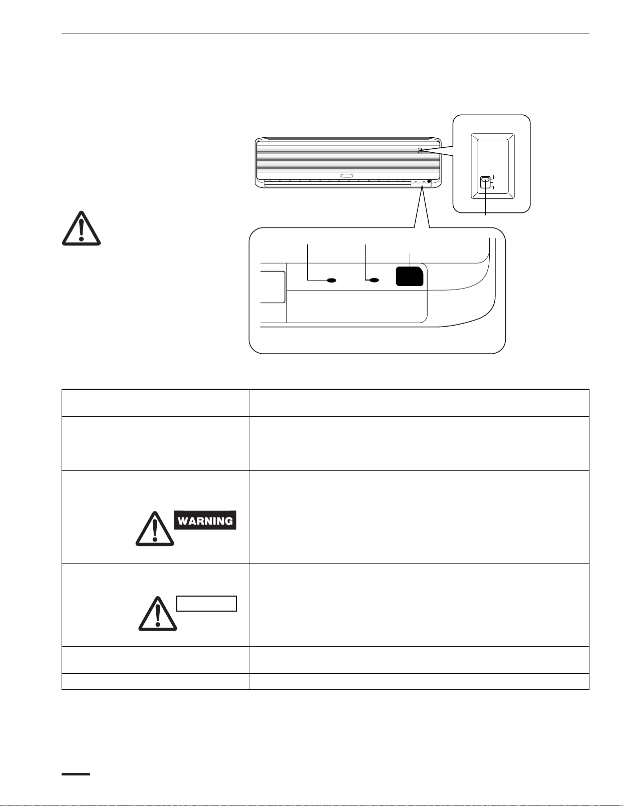
Unit Display and Operation Selector
INDOOR UNIT
ON
OFF
TEST
IMPORTANT
Avoid using radio equipment
such as mobile phone near
(within 4 ft. of) the indoor unit.
Some radio equipment may
cause the unit to malfunction.
If the trouble occurs, disconnect power and restart the
air conditioner after a few
minutes.
REMOTE CONTROL
receiver
Operation selector
ON position This position is for operating the air conditioner with the wireless
OFF position Switch the selector to the OFF position if you are not going to use
Operation selector
OPERATION lamp
OPERATION
TIMER lamp
TIMER
Remote control
receiver
This section picks up infrared signals from the remote control unit
(transmitter).
remote control unit.
Set the selector normally in this position.
the air conditioner for a few days or longer.
The OFF position does not disconnect the power. Use the main
power switch to turn off power completely.
TEST position This position is used only when servicing the air conditioner.
CAUTION
Do not set the operation selector at the TEST position for normal
operation.
OPERATION lamp This lamp lights when the system is in the continuous DRY and
COOL mode.
TIMER lamp This lamp lights when the system is being controlled by the timer.
6OI-508-06EG
Page 7
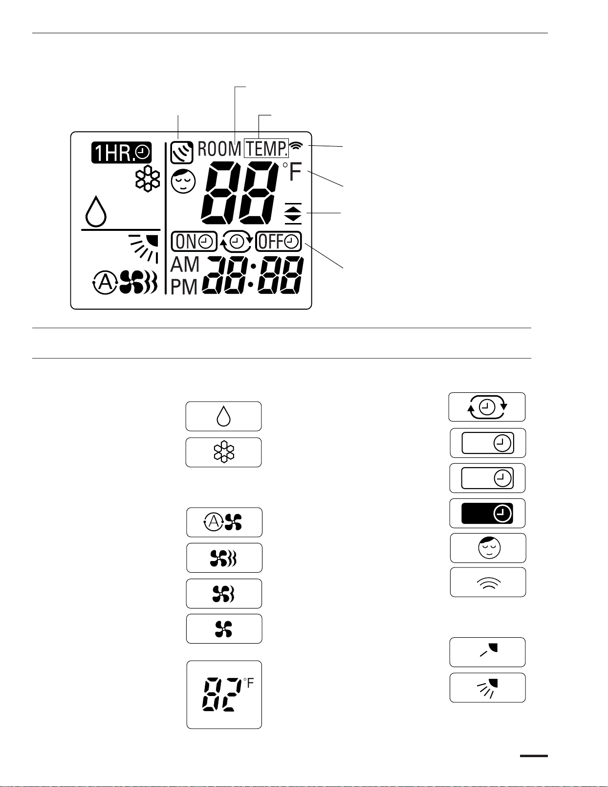
Remote Control Unit (Display)
Displayed when main unit sensor is in use
“ROOM TEMP” is displayed when the temperature setting has
not been made.
“TEMP” is displayed when setting temperature.
Displayed when transmitting data
Displayed when temperature is
shown
Displayed when the temperature
setting is at the upper or lower
allowable limit
Displayed when setting timer
(1) Operation mode
MILD DRY................................
COOL.......................................
(2) Fan speed
AUTO.......................................
HIGH........................................
MEDIUM..................................
LOW.........................................
Symbols
(4) Timer
(5) NIGHT SETBACK....................
(6) Confirmation of
(7) Flap
24-hour clock with ON/OFF
program Timer .......................
24-hour ON Timer..................
24-hour OFF Timer.................
1-hour OFF Timer...................
transmission...........................
ON
OFF
1
HR.
(3) Temperature setting
60—86 °F
When set to 82 °F
temperature indication......
Angle indication.....................
Sweep indication....................
7OI-508-07EG
Page 8
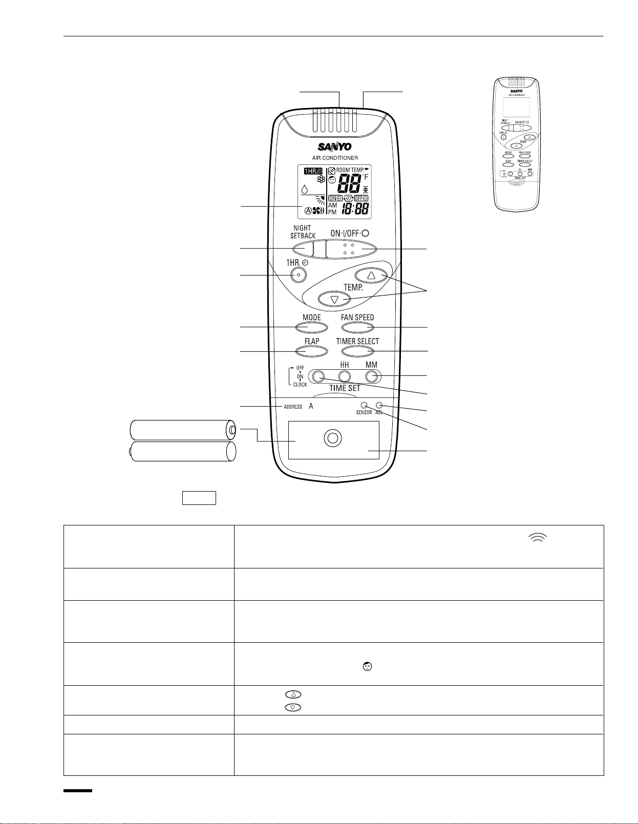
Remote Control Unit
Display
NIGHT SETBACK button
1 HR. TIMER button
MODE selector button
FLAP button
ADDRESS switch
Sensor
Transmitter
(Cover closed)
ON/OFF operation button
Temperature setting buttons
FAN SPEED selector button
TIMER SELECT button
TIMER AND PRESENT TIME
setting buttons
PROGRAM button
ACL button
SENSOR button
Battery compartment
(Pull off the cover to expose the
batteries.)
NOTE The illustration above pictures the remote control unit after the cover has been
lowered and removed.
Transmitter When you press the buttons on the remote control unit, the mark
appears in the display to transmit the setting changes to the receiver in
the air conditioner.
Sensor A temperature sensor inside the remote control unit senses the room
temperature.
Display Information on the operating conditions is displayed while the remote control
unit is switched on. If the unit is turned off, only the mode that was set
previously is still displayed.
NIGHT SETBACK button For details, see “Night Setback Mode”. When you press this button in the
DRY or COOL mode, the mark appears in the display, and the remote
control unit automatically adjusts the set temperature to save energy.
Temperature setting Press the button to increase the set temperature.
buttons (TEMP.) Press the button to reduce the set temperature.
ON/OFF operation button This button is for turning the air conditioner on and off.
Timer and Present Time First, press the program button to select the mode you want.
setting buttons Each time you press the “HH” button, the hours advance by one.
Each time you press the “MM” button, the minutes advance by one.
8
OI-508-08EG
Page 9

Remote Control Unit (continued)
Program button For details, see “Setting the Timer”.
Press this button to select the mode you want to program.
TIMER SELECT button No display : The timer does not operate.
: The air conditioner stops at the set time.
: The air conditioner starts at the set time.
: The air conditioner stops and starts, or starts and stops, at the
set times every day.
MODE selector button Use this button to select the DRY or COOL mode.
(DRY)
(COOL)
FLAP button Press this button either to select to set the airflow direction to one of the six
possible positions manually, or to select the sweep function, which moves
the flap up and down automatically.
NOTE When you press the FLAP button, the air flow direction will be changed one
by one as follows.
: The air conditioner reduces the humidity in the room.
: The air conditioner makes the room cooler.
: The airflow direction can be set manually. (six positions)
: The flap moves up and down automatically.
Swing
FAN SPEED selector button
: The air conditioner automatically decides the fan speeds.
: High fan speed
: Medium fan speed
: Low fan speed
1 HR. TIMER button
: When you press this button, regardless of whether the unit is
(1-HOUR OFF TIMER) operating or stopping, the unit operates for one hour and then
shuts down.
ACL button (ALL CLEAR) Puts the remote control unit into pre-operation status. Always press this
button after replacing the batteries.
•
ADDRESS switch
Change the address switch to prevent mixing of signals from remote control
units when two Sanyo air conditioners are installed next to each other.
Normally, the address switch is set to A. When switching the address, the
remote control must be changed, and the jumper cables on the indoor unit
board must be cut. For more information, please contact the dealer where
you made the purchase.
•
Normally, the tabs on the remote control unit should not be bent.
SENSOR button When you press this button (use a small-tipped object such as a ballpoint
pen), the
mark will appear at the display. And the room temperature is
detected by the sensor which is built into the indoor unit and the air
conditioner is controlled accordingly.
NOTE If the remote control is located near a heat source, such as a space heater or
in direct sunlight, press the SENSOR button to switch to the sensor on the
indoor unit.
NOTE The remote control unit sends the temperature signal to the air conditioner regularly at five minute intervals.
If the signal from the remote control unit stops for more than ten minutes due to the loss of the remote
control unit or other trouble, the air conditioner will switch to the temperature sensor which is built into
the indoor unit and control the room temperature. In these cases, the temperature around the remote
control unit may differ from the temperature detected at the air conditioner’s position.
OI-508-9EG
9
Page 10

How to Install Batteries
NOTE
Using the Remote Control Unit
1. Slide the cover in the direction indicated by
the arrow and remove it.
2. Install two AAA alkaline batteries. Make sure
the batteries point in the direction marked in
the battery compartment.
3. Use a thin object such as the tip of a pen to
press the ACL button.
ACL button
•
The batteries last about six months, depending on how much you use
the remote control unit. Replace the batteries when the remote control
unit’sdisplayfailstoindicate,orwhentheremotecontrolcannotbe
used tochangetheairconditioner’ssettings.
•
Use two fresh leak-proof type-AAA alkaline batteries.
•
In replacing batteries, follow the instructions as mentioned in the
sub-section ‘‘How to Install Batteries’’.
•
If you do not use the remote control unit more than 1 month, take out
the batteries.
How to Use the Remote
Control Unit
Remote Control Unit
Installation Position
DO NOT
When using the remote control unit, always point the unit’s transmitter
head directly at the air conditioner’s receiver.
Air conditioner
(Indoor unit)
Receiver
Remote control
(Transmitter head)
unit
The remote control unit may be operated either from a non-fixed position
or from a wall-mounted position. To ensure that the air conditioner operates
correctly, DO NOT install the remote control unit in the following places:
•
In direct sunlight
•
Behind a curtain or other places where it is covered
•
More than 26 feet (8 m) away from the air conditioner
•
In the path of the air conditioner’s airstream
•
Where it may become extremely hot or cold
•
Where it may be subject to electrical or magnetic noise
•
Where there is an obstacle between the remote control unit and air
conditioner (since a check signal is sent from the remote control unit
every 5 minutes)
10OI-508-10EG
Page 11

Using the Remote Control Unit (continued)
Mounting the Remote
Control Unit
Truss-head
tapping screws
5/32 x 5/8 “ (4 x 16 mm)
(supplied)
Press
Remote
control
unit holder
When attaching to wall 1) Confirm the indoor unit beeps when the ON/OFF button is pressed at the
wall location where the remote control unit is to be attached, then attach
the holder to the wall.
Hook
When using the remote
control unit indoor unit when operating the remote control unit and the air conditioner.
Securing the remote 1) Attach the holder to the wall with one screw in the upper hole only.
control unit to prevent theft
2) When taking out the remote control unit, pull it from the holder.
•
Point the transmitter on the remote control unit at the sensor on the
•
Do not place objects which may block the transmitted signals between
the receiver and the remote control unit.
Truss-head
tapping screws
5/32 x 5/8 “ (4 x 16 mm)
(supplied)
Holder
Remote
control
unit holder
2) Remove the cover from the remote control unit, and then remove the
batteries. Next, place the remote control unit in the holder.
OI-508-11EG
3) Secure both the remote control unit and the holder to the wall with another
screw through the lower hole.
4) Put the batteries back in the remote control unit, and then replace the
cover.
11
Page 12

1. Manual Operation
Operation with the Remote
Control Unit
STEP 2
STEP 3
NOTE
STEP 1
STEP 5
Check that the circuit breaker on the power panel is turned on and that the
operation selector of the indoor unit is in the ON position.
Press the setting buttons as described below and change the settings as
desired.
STEP 1 Press the MODE selector button and select the desired
mode.
For drying operation →
For cooling operation
STEP 2
STEP 3 Press the temperature setting buttons to change the
NOTE
To start the air conditioner, press the ON/OFF
operation button.
temperature setting to the desired temperature.
Adjustable temperature range:
The temperature setting changes by two degrees each
time the button is pressed. (The air conditioner
remembers the new temperature setting even when it is
turned off.)
STEP 4
→
86 °F max.
60 °F min.
STEP 4
NOTE
STEP 5 Press the FLAP button and set the airflow direction as
To stop the air conditioner, press the ON/OFF operation button again.
12 OI-508-12EG
Set the FAN SPEED selector button to the setting you want.
If the fan speed is set to (Automatic), the fan speed
switches automatically, according to the difference
between the actual room temperature and the temperature
setting.
desired.
(Refer to ˝Adjusting the Airflow Direction˝ on page 19.)
Page 13

NOTE
2. Adjusting the
Fan Speed
A. Automatic Simply set the FAN SPEED selector button to the position.
Cooling and DRY mode:
Operation with the Remote Control Unit (continued)
•
This appliance has a built-in three minutes time delay circuit to ensure
reliable operation. When the operation button is pressed, the
compressor will start running within three minutes. In the event of
power failure, the unit will stop. When the power is restored, the unit
will restart automatically after five minutes.
A microcomputer in the air conditioner automatically controls the fan speed
when the
the difference between the room temperature and the set temperature is
detected by the microcomputer which then automatically switches the fan
speed to the most suitable level.
When difference between
room temperature and set
temperature is
4 °F and over High
Between 4 °F and 2 °F Medium
Below 2 °F Low
mode is selected. When the air conditioner starts operating,
FAN SPEED
NOTE
B. Manual If you want to adjust fan speed manually during operation, just set the FAN
The above mentioned data make reference to the conditioner operating
when the sensor on the remote control unit is ON. (Refer to temperature
sensor selector). If the sensor on the indoor unit is being used then
actual operation will slightly differ from that described in the above
tables. (
SPEED selector button as desired. [
Sign shown on the remote control unit display.)
, ,or ]
13OI-508-13EG
Page 14

3. Night Setback Mode
Operation with the Remote Control Unit (continued)
In Cooling and DRY
Mode:
(
and )
The Night Setback Mode is used for saving energy.
Press the NIGHT SETBACK button while the air conditioner is operating.
The
To cancel the night setback function, press the NIGHT SETBACK button
again.
mark appears in the display.
When the night setback mode is selected, the air conditioner
automatically raises the temperature setting 2 °F when 30 minutes
have passed after the selection was made, and then another 2 °F after
another 30 minutes have passed, regardless of the indoor temperature
when night setback was selected. This enables you to save energy
without sacrificing comfort. This function is convenient when gentle
cooling is needed.
Setting
temperature
2°F
2°F
30 min.
Press the
NIGHT SETBACK
button
14 OI-508-14EG
30 min.
Time
Page 15

‘‘DRY’’ ( ) Operation
Special Remarks
How it works?
Power failure
during operation
Clicking Sound
Clicking sound is
heard from the air
conditioner
Remote Control Unit
•
Once the room temperature reaches the level that was set, the unit
repeats the cycle of turning on and off automatically.
•
During DRY operation, the fan speed is automatically set to LOW or
VERY LOW; the fan speed then switches back and forth between LOW
(for 20 seconds) and VERY LOW (for 10 seconds).
•
‘‘DRY’’ operation is not possible if the indoor temperature is 59 °F or
less.
•
In the event of power failure, the unit will stop. When the power is
turned on again, the unit restarts within five minutes.
•
In cooling and drying operation, any plastic parts may expand or shrink
due to a sudden temperature change. In this event, a clicking sound
may occur. This is normal, and the sound will soon disappear.
•
The remote control unit sends the setting condition to the air
conditioner regularly at five minute intervals.
15OI-508-15EG
Page 16

Setting the Timer
3
4
1
1. How to set the
present time
2. How to set the OFF time
2
(Example) To set to 9:10 pm.
Operation Indication
1. Press the Program button ( )
three times.
2. • Press the HH button until PM 9 is
displayed.
• Press the MM button until 10 is
displayed.
(Example) To stop the air conditioner at 11:30 pm.
1. Press the Program button ( )
once.
The time indication alone blinks.
The display will automatically
stop blinking except for the “:”
symbol after 10 sec.
The timer
and present OFF time is shown.
indication blinks
16
2. • Press the HH button until PM 11 is
displayed.
• Press the MM button until 30 is
displayed.
3. Press the ON/OFF button to start the
air conditioner.
4. Press the TIMER SELECT button to
set OFF time.
The display will change
automatically back to show the
present time after 10 sec.
The present time is displayed.
The present time and
displayed.
are
OI-508-16EG
Page 17

Setting the Timer (continued)
3. How to set the ON time
4. How to set a program
for daily ON/OFF
operation
(Example) To start operation at 7:10 am.
Operation Indication
1. Press the Program button ( )
twice.
2.•Press the HH button until AM 7 is
displayed.
•
Press the MM button until 10 is
The timer indication blinks
and present ON time is shown.
The display will change
automatically back to show the
present time after 10 sec.
displayed.
3. Press the ON/OFF button to start the
The present time is displayed.
air conditioner.
4. Press the TIMER SELECT button to
set ON time.
The present time and are
displayed.
(Example) To start operation at 7:10 am. and stop the air conditioner at
11:30 pm.
Present
time
OFF
time
ON
time
Programed
daily
ON/OFF
7:10 am 11:30 pm
ON OFF
1. Set the timer ON/OFF times as
shown in 2-1, 2 and 3-1, 2.
2. Press the ON/OFF button to start the
air conditioner.
3. Press the TIMER SELECT button to
set the ON/OFF combination timer.
The present time PM 9:10 and
are displayed.
NOTE When the Daily ON/OFF program is set to start the air conditioner
before the ON time setting, the
indications appear on the
display.
On the other hand, when the Daily ON/OFF program is set to start the
air conditioner after the ON time setting, the
indications
appear on the display. Thus, these indications show the timer program
which will operate next.
OI-508-17EG
NOTE You can check the timer ON/OFF times after you have set them by
pressing the PROGRAM button.
17
Page 18

1. 1-Hour OFF Timer
Setting the 1-Hour OFF Timer
This function causes the unit to operate for one hour and then stop, regardless
of whether the unit is on or off when this button is pressed.
The
Setting procedure:
Regardless of whether the unit is operating or stopped, press the 1 HR. TIMER
button.
Cancellation procedure:
Press the ON/OFF operation button to turn the unit off, wait for the unit to stop
operating, and then press the ON/OFF operation button again. The 1-Hour Timer
function is now cancelled and the unit operates normally.
indicator in the display indicates that this function is operating.
appears in the display.
2. Operation Together
with the Program Timer
NOTE
•
If, while the 1-Hour Timer function is operating, the 1 HR. TIMER button is
pressed once to cancel the function and then again, the unit continues to
operate for one hour from that point in time and then stops.
•
The 1-Hour OFF Timer setting is given priority over the daily program
setting.
•
It is not possible to use the OFF Timer and 1-Hour OFF Timer together.
Whichever function is set last takes precedence.
If the 1 HR. TIMER button is pressed while the TIMER OFF function operates,
OFF Timer is cancelled and the unit will stop operating one hour later
18
OI-508-18EG
Page 19

Adjusting the Airflow Direction
COOL
and
DRY
(Recommended
operating
range)
SWEEP
1. Horizontal The horizontal airflow can be adjusted by moving the vertical vanes with your
hands to the left or right.
CAUTION When the humidity is high, the vertical vanes should be in the front
position during the cooling or drying operation. If the vertical vanes
are positioned all the way to the right or left, condensation may begin
to form around the air vent and drip down.
2. Vertical The vertical airflow can be adjusted by moving the flap with the remote
control unit. Do not move the flap with your hands. Confirm that the remote
control unit has been turned on. Use the FLAP button to set either the
sweep function or one of the six airflow direction settings.
(The maximum capacity is obtained at the position at 4.)
A. Sweep function B. Setting the airflow manually
OI-508-19EG
The flap starts moving up and down to
deliver air over the sweep range.
NOTE
CAUTION
•
The flap automatically closes when the unit is off.
•
Use the FLAP button on the remote control to adjust the position of the flap.
If you move the flap by hand, the flap position according to the remote control
and the actual flap position may no longer match. If this should happen, shut
off the unit, wait for the flap to close, and then turn on the unit again; the flap
position will now be normal again.
•
Do not have the flap pointed down during cooling operation.
Condensation may begin to form around the air vent and drip down.
Referring to the above illustration, use
the FLAP button to set the airflow
direction within the range used during
the cooling or drying operation.
19
Page 20

INDOOR UNIT
Operation without the Remote
Control Unit
If you have lost the remote control unit or it has trouble, follow the steps below.
ON
OFF
TEST
Operation
selector
WARNING
1. When the air conditioner is not running
If you want to turn on the air conditioner, switch the operation selector to the
OFF position, and then to the ON position.
NOTE The set temperature and fan speed are automatically set at the last
selection before stopping.
2. When the air conditioner is running
If you want to turn off the air conditioner, switch the operation selector to the
OFF position.
Care and Cleaning
1. For safety, be sure to turn the air conditioner off and also to disconnect
the power before cleaning.
2. Do not pour water on the indoor unit to clean it. This will damage the
internal components and cause an electric shock hazard.
20
Casing and Grille
(Indoor Unit)
CAUTION
Clean the casing and grille of the indoor unit with a vacuum cleaner brush,
or wipe them with a clean, soft cloth.
If these parts are stained, use a clean cloth moistened with a mild liquid
detergent. When cleaning the grille, be careful not to force the vanes out of
place.
1. Never use solvents, or harsh chemicals when cleaning the indoor unit.
Do not wipe the plastic casing using very hot water.
2. Some metal edges and the fins are sharp and may cause injury if handled
improperly; be especially careful when you clean these parts.
3. The internal coil and other components of the outdoor unit must be
cleaned every year. Consult your dealer or service center.
OI-508-20EG
Page 21

Care and Cleaning (continued)
Air intake grille
Anti-mold
filter
Insert into the groove on the unit.
Anti-mold filter The anti-mold filter behind the air intake grille should be checked and cleaned
at least once every two weeks.
How to remove the
anti-mold filter
Cleaning Use a vacuum cleaner to remove light dust. If there is sticky dust on the filter,
How to replace the
anti-mold filter
1. Grasp both ends of the
air intake grille and
Air intake grille
pull it out and up.
2. Push the anti-mold
filter up slightly, and
then pull it down.
Anti-mold filter
wash the filter in lukewarm, soapy water, rinse it in clean water and dry it.
1. With the ˝FRONT˝ mark facing
you, slide the anti-mold filter
up into the unit and then
lower the handle into the
groove on the unit.
2. After installing the anti-mold
filter, press the locations
marked by the arrows ( )
and close the air intake grille.
OI-508-21EG
21
Page 22

Care and Cleaning (continued)
Air clean filter
(STK-F4B)
Air cleaning filter
(not provided)
NOTE
WARNING The air cleaning filter cannot remove harmful gases or vapors nor ventilate air
How to install the air
cleaning filter
NOTE
The air cleaning filter removes dust and dirt from the air, and reduces odors
and smoke from tobacco.
The air clean filter is not provided with the air conditioner and must be purchased
separately.
Ask for the STK-F4B model when purchasing.
in the room. You must open doors or windows frequently when you use gas or
oil heating appliances. Otherwise there is a risk of suffocation in extreme cases.
The air cleaning filter needs to be
installed behind the anti-mold filter.
1. Remove the anti-mold filter.
2. To mount the STK-F4B, set the
air clean filter (sold separately)
at the mounting position with
the black side facing the rear.
3. Reinstall the anti-mold filter,
and close the suction grill.
•
In general, the filter should be
replaced once every three
months.
Cleaning the main unit and
remote control unit
•
Dirty air clean filters cannot be
washed and reused. Purchase a
replacement filter at your local
dealer.
• Wipe clean using a soft, dry cloth.
• To remove stubborn dirt, moisten a cloth in warm water no hotter than
104°F, wring thoroughly, and then wipe.
• The air intake grille can be removed in order to wash it with water.
22
OI-508-22EG
Page 23

Care and Cleaning (continued)
Removing and remounting
the air intake grille
CAUTION When using a footstool or the like, be careful not to let it tip over.
Washing the grille with
water
•
With the air intake grille open all
Air intake grille
the way, grip both arms with
your hands and pull toward you
Arm
to remove.
To remount, hold the air intake
grille roughly horizontal and
push it in until the arm shafts fit
into the indentations in the main
unit, then fit the grille into place.
•
Clean the grille gently using a soft sponge, or the like. Then wipe away any
remaining moisture.
•
Neutral detergent may be used to remove stubborn dirt. Then rinse thoroughly
with water and wipe away any remaining moisture.
Do not
Do
Tips for Energy Saving
•
Block the air intake and outlet of the unit. If they are obstructed, the
unit will not work well, and may be damaged.
•
Let direct sunlight into the room. Use sunshades, blinds or curtains. If
the walls and ceiling of the room are warmed by the sun, it will take
longer to cool the room.
•
Always try to keep the air filter clean. (Refer to “Care and Cleaning“.)
A clogged filter will impair the performance of the unit.
•
To prevent conditioned air from escaping, keep windows, doors and any
other openings closed.
OI-508-23EG
23
Page 24

Troubleshooting
If your air conditioner does not work properly, first check the following points before requesting service. If it still
does not work properly, contact your dealer or service center.
Trouble Possible Cause Remedy
Air conditioner does not
run at all.
1. Power failure.
2. Leakage circuit breaker tripped.
3. Line voltage is too low.
4. Operation button is OFF.
5. Batteries in remote control unit
have run down.
1. Restore power.
2. Contact service center.
3. Consult your electrician or dealer.
4. Press the button again.
5. Replace batteries.
OPERATION lamp flashes
and air conditioner does
not operate.
Compressor runs but soon
stops.
Poor cooling performance.
Clicking sound is heard
from the air conditioner.
OPERATION lamp lights
but outdoor unit will not
run.
Trouble in wiring system. Contact service center.
Obstruction in front of condenser coil. Remove obstruction.
1. Dirty or clogged air filter.
2. Heat source or many people in
room.
3. Doors and/or windows are open.
4. Obstacle near air intake or air
discharge port.
5. Thermostat is set too high for
cooling.
In cooling and drying operation, any
plastic parts may expand or shrink
due to a sudden temperature change.
In this event, a clicking sound may
occur.
1. The use of portable telephones
near the air conditioner may cause
disturbance to its normal
operation.
1. Clean air filter to improve airflow.
2. Eliminate heat source if possible.
3. Shut them to keep the heat out.
4. Remove it to ensure good airflow.
5. Set the temperature lower.
This is normal, and the sound will
soon disappear.
1. Turn off the power then restart the
air conditioner after 1 minute.
2. Consult your dealer.
Operating Range
The air conditioner is operable within the temperature ranges as listed below:
Temperature Indoor Air Intak e Temperature Outdoor Air Intake Temperature
Cooling Model
Low Ambient
Temperature
Model
24
Maximum 95 °F DB/71 °F WB 115 °F DB
Minimum 67 °F DB/57 °F WB 67 °F DB
Maximum 95 °F DB/71 °F WB 115 °F DB
Minimum 67 °F DB/57 °F WB 0 °F DB
SANYO FISHER COMPANY
A DIVISION OF SANYO NORTH AMERICA CORPORATION
21605 Plummer Street
Chatsworth, CA 91311 U.S.A.
In Canada
SANYO Canada Inc.
300 Applewood Crescent,
Concord, Ontario,
L4K 5C7, Canada
OI-508-24EG
 Loading...