

Page 1
TEST RUN SERVICE MANUAL
R410A Models
Indoor Units
Class 7 9 12 18 24 36 48
X 4-Way Air Discharge Semi-Concealed XHX1252 XHX1852 XHX2452 XHX3652
A 1-Way Air Discharge Semi-Concealed AHX0752 AHX0952 AHX1252
U Concealed-Duct UHX0752 UHX1252 UHX1852 UHX2452 UHX3652
D Concealed-Duct High-Static Pressure DHX3652 DHX4852
T Ceiling-Mounted THX1252 THX1852 THX2452
K Wall-Mounted KHX0752 KHX0952 KHX1252 KHX1852 KHX2452
Outdooe Units
Class 90 140
C ECO-i W-2WA Y CHDX09053 CHDX14053
85464849257000
REFERENCE NO.
SM830157
Page 2
i
Page 3
Check of Density Limit
The room in which the air conditioner is to be
installed requires a design that in the event of refrigerant gas leaking out, its density will not exceed a set
limit.
The refrigerant (R410A), which is used in the air conditioner, is saf e, without the toxicity or combustibility of
ammonia, and is not restricted by laws imposed to protect
the ozone layer. Ho w ever, since it contains more than air,
it poses the risk of suffocation if its density should rise
excessively. Suffocation from leakage of refrigerant is
almost non-existent. With the recent increase in the number of high density buildings, however, the installation of
multi air conditioner systems is on the increase because of
the need for effective use of floor space, individual control,
energy conservation by curtailing heat and carrying power,
etc.
Most importantly, the multi air conditioner system is able
to replenish a large amount of refrigerant compared to
conventional individual air conditioners. If a single unit
of the multi air conditioner system is to be installed in a
small room, select a suitable model and installation procedure so that if the refrigerant accidentally leaks out,
its density does not reach the limit (and in the event of
an emergency, measures can be made before injury can
occur).
In a room where the density may exceed the limit, create
an opening with adjacent rooms, or install mechanical
ventilation combined with a gas leak detection device.
The density is as given below.
Total amount of refrigerant (lbs)
Min. volume of the indoor unit installed room (ft.
<
Density limit (oz/ft.
3
)
3
)
The density limit of refrigerant which is used in multi air
conditioners is 0.3 oz/ft.
3
(ISO 5149).
NOTE
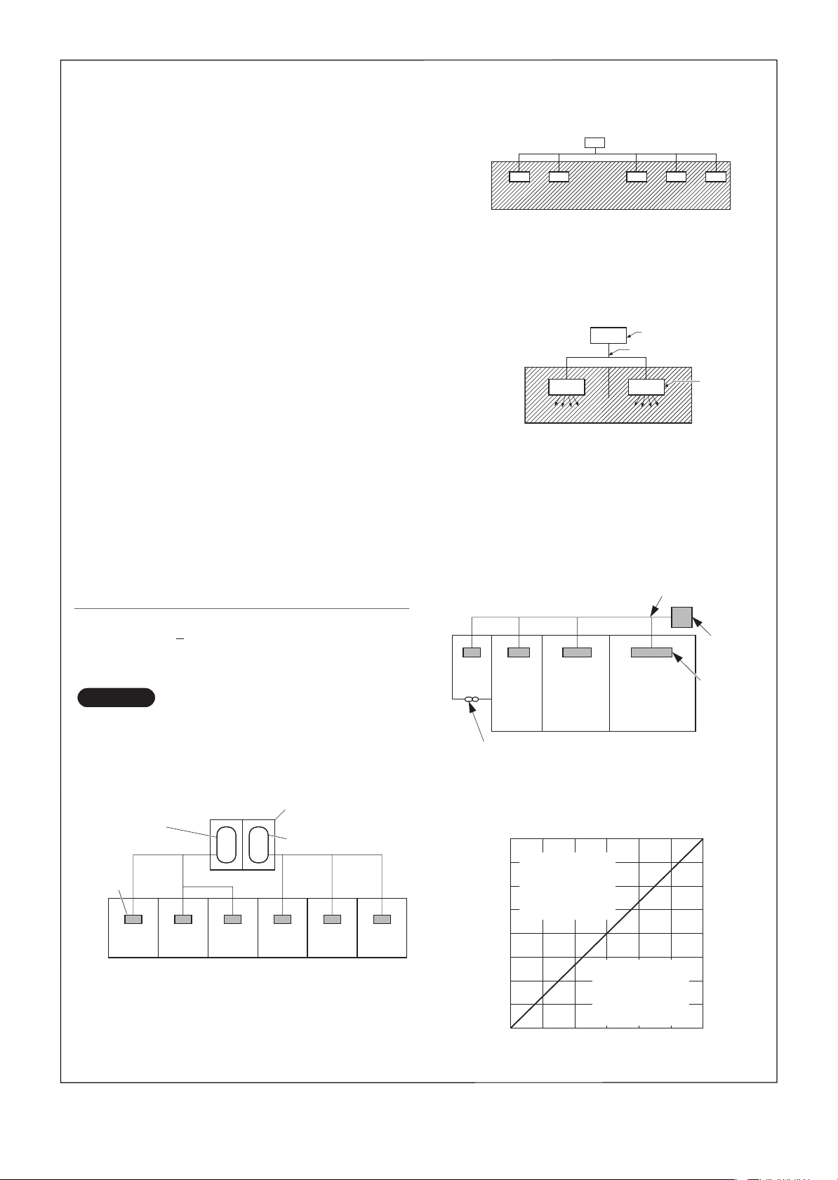
1.If there are 2 or more refrigerating systems in a single
refrigerating device, the amount of refrigerant should be
as charged in each independent device.
For the amount of charge in this example:
Outdoor unit
e.g., charged
amount (353 oz)
Indoor unit
Room A Room B Room C Room D Room E Room F
e.g., charged
amount (529 oz)
The possible amount of leaked refrigerant gas in
rooms A, B and C is 353 oz.
The possible amount of leaked refrigerant gas in
rooms D, E and F is 529 oz.
2. The standards for minimum room volume are as follows.
(1) No partition (shaded portion)
(2) When there is an effective opening with the adjacent
room for ventilation of leaking refrigerant gas (opening without a door, or an opening 0.15% or larger
than the respective floor spaces at the top or bottom
of the door).
Outdoor unit
Refrigerant tubing
Indoor unit
(3) If an indoor unit is installed in each partitioned room
and the refrigerant tubing is interconnected, the
smallest room of course becomes the object. But
when mechanical ventilation is installed interlocked
with a gas leakage detector in the smallest room
where the density limit is exceeded, the volume of the
next smallest room becomes the object.
Refrigerant tubing
Outdoor unit
Very
small
room
Small
room
Mechanical ventilation device – Gas leak detector
Medium
room
Large room
Indoor unit
3. The minimum indoor floor space compared with the
amount of refrigerant is roughly as follows: (When the
ceiling is 8.8 ft. high)
3
ft.
4000
3500
3000
2500
2000
1500
Min. indoor volume
1000
Range below
the density limit of
0.3 oz/ft.
(countermeasures
not needed)
500
0 0
0
3
Range above
the density limit of
0.3 oz/ft.
(countermeasures
needed)
400 200 600 800 1000 1200
Total amount of refrigerant
3
2
ft.
454
398
341
284
227
170
114
Min. indoor floor area
57
oz
(when the ceiling is 8.8 ft. high)
ii
Page 4

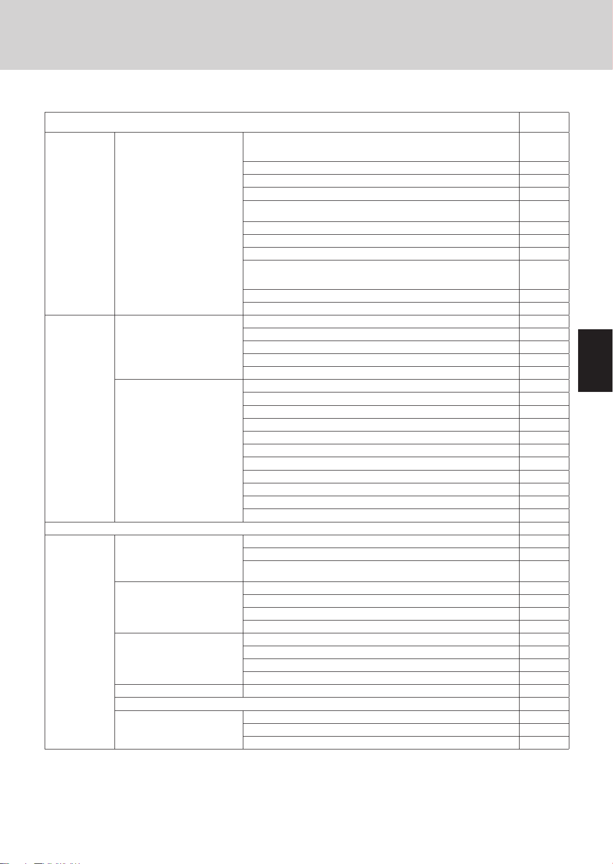
Contents
Section 1: TEST RUN ..............................................................................................................1-1
1. Test Run ...........................................................................................................1-2
2. Setting of Unit Control PCB .............................................................................1-4
3. Auto Address Setting .......................................................................................1-6
4. Remote Controller Test Run Settings .............................................................1-12
5. Caution for Pump Down .................................................................................1-13
6. Meaning of Alarm Messages .........................................................................1-14
Section 2: REMOTE CONTROL FUNCTIONS ........................................................................2-1
1. Main Operating Functions ................................................................................2-2
2. Wireless Remote Controller .............................................................................2-4
3. Timer Remote Controller (RCS-TM80BG) .....................................................2-15
Section 3: TROUBLE DIAGNOSIS .........................................................................................3-1
1. Contents of Remote Controller Switch Alarm Display ......................................3-2
2. Outdoor Unit Control PCB LED Display ...........................................................3-4
3. W-2WAY ECO-i Alarm Codes ..........................................................................3-5
4. Blinking
Section 4: PCB AND FUNCTIONS .........................................................................................4-1
1. Outdoor Unit Control PCB................................................................................4-2
2. Indoor Unit Control PCB ..................................................................................4-6
(Inspection) Display on the Remote Controller ............................3-22
Section 5: SELF-DIAGNOSIS FUNCTION TABLE .................................................................5-1
1. Self-Diagnosis Function Table ..........................................................................5-2
Section 6: SERVICE CHECKER .............................................................................................6-1
1. Outdoor Unit Maintenance Remote Controller .................................................6-2
iii
Page 5

Test Run
Contents
1. TEST RUN
1. Test Run ..............................................................................................................................1-2
1. Preparing for Test Run ......................................................................................................1-2
2. Test Run Procedure ..........................................................................................................1-3
2. Setting of Unit Control PCB ...............................................................................................1-4
1. Main Outdoor Unit PCB Setting ........................................................................................1-4
3. Auto Address Setting .........................................................................................................1-6
1. Auto Address Setting ........................................................................................................1-6
4. Remote Controller Test Run Setting ...............................................................................1-12
5. Caution for Pump Down ...................................................................................................1-13
6. Meaning of Alarm Messages ...........................................................................................1-14
1
2
3
4
5
1-1
6
7
8
Page 6
1
2
1. T est Run
1. Preparing for Test Run
Before attempting to start the air conditioner, check the fol-
z
lowing.
(1) All loose matter is removed from the cabinet, especially
steel fi lings, bits of wire, and clips.
(2) The control wiring is correctly connected and all electrical
connections are tight.
(3) The protective spacers for the compressor used for trans-
portation have been removed. If not, remove them now.
(4) The transportation pads for the indoor fan have been
removed. If not, remove them now.
(5) The power has been connected to the unit for at least 5
hours before starting the compressor. The bottom of the
compressor should be warm to the touch and the crankcase heater around the feet of the compressor should be
hot to the touch.
(6) Both the gas and liquid tube service valves are open. If
not, open them now.
(7) Request that the customer be present for the trial run.
Explain the contents of the instruction manual, then have
the customer actually operate the system.
(8) Be sure to give the instruction manual and warranty cer-
tifi cate to the customer.
(9) When replacing the control PCB, be sure to make all the
same settings on the new PCB as were in use before
replacement.
The existing EEP ROM is not changed, and is connected
to the new control PCB.
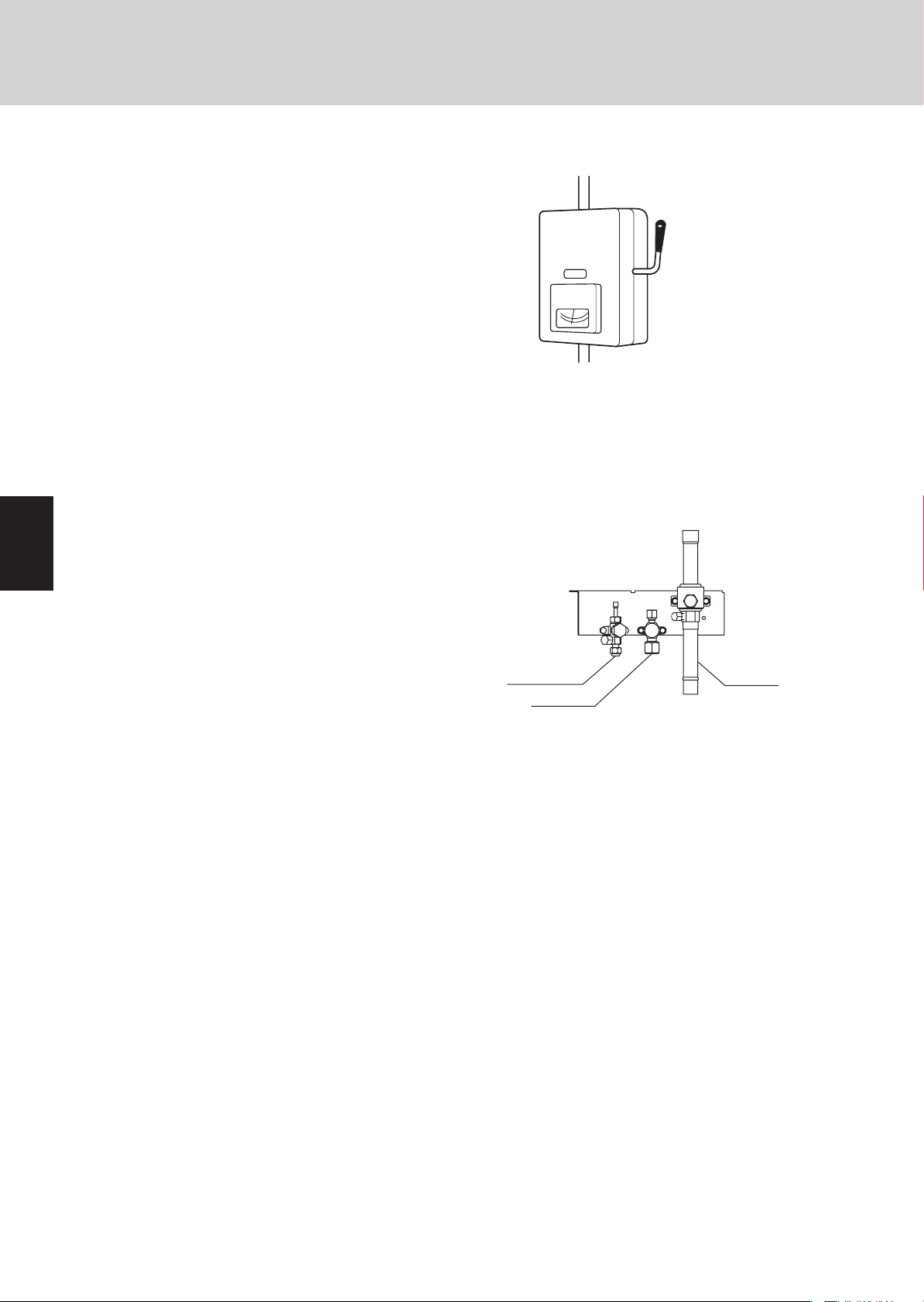
Power mains switch
Balance tube
Liquid tube
Test Run
ON
(Power must be turned ON
at least 5 hours before
attempting test run)
Gas tube
3
4
5
6
7
8
1-2
Page 7
1. T est Run
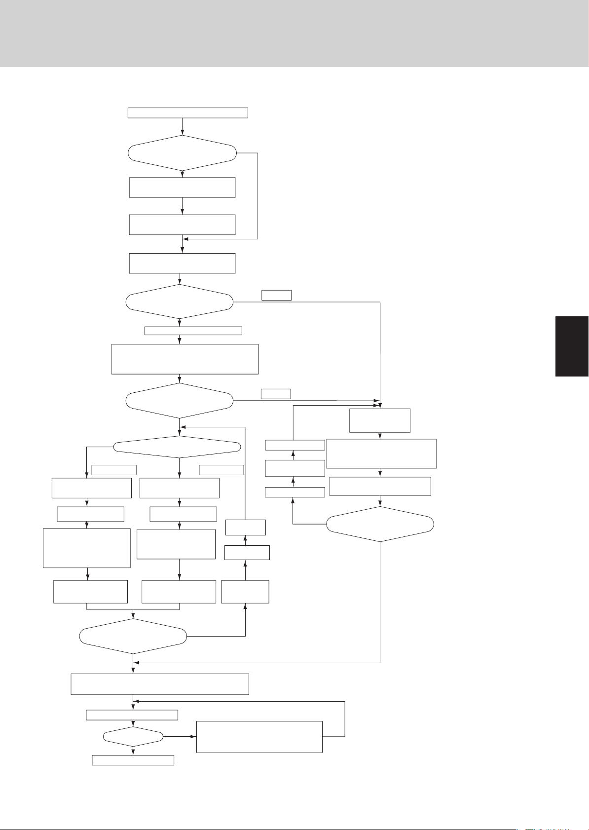
2. Test Run Procedure
Test Run
<Outdoor unit control PCB>
Unit No. setting switch
(S007)
<Outdoor unit control PCB>
Unit No. setting switch
(S006)
<Outdoor unit control PCB>
Unit No. setting switch
(S004 and S005)
(Check the link wiring.)
<Outdoor unit control PCB>
Unit No. setting switch
(S002 and S003)
When multiple outdoor main units exist, disconnect the terminals
extended from the shorted plugs (CN003) at all outdoor main unit
NO
CASE 3B CASE 3A
Is it OK to start the compressors?
Recheck the items to check before the test run.
Have the outdoor sub units been connected?
YES
Set the unit address.
Set the No. of outdoor units.
Set the No. of indoor units.
Are the inter-unit control wires
connected to more than 1 refrigerant
system?
YES
Set the system address.
Alternatively, move the sockets to the OPEN side.
PCBs except for 1.
Is it possible to turn ON the power only
for the 1 refrigerant system where the
test run will be performed?
NO
Will automatic address setting be
performed in Heating mode?
YES
Is it OK to start the compressors?
NO
*1
*1
YES
The unit with the unit
No. set to 1 is the
main unit. All other
units are sub units.
CASE 1
NO
Note: It is not necessary to remove
the socket that is used to shortcircuit the terminal plugs from
the outdoor sub unit PCBs.
CASE 2
Make necessary corrections.
Turn OFF the indoor and
outdoor unit power.
Check the alarm contents.
Items to Check Before the Test Run
1. Turn the remote power switch on at least 5 hours before
the test, in order to energize the crankcase heater.
2. After performing the leak inspection, applying vacuum,
and performing refrigerant charge for the tubing which
is connected on-site, fully open the outdoor unit service
valve. However if only one outdoor unit is installed, a
balance tube is not used. Therefore, leave the valve fully
closed.
3. When replacing the control PCB, be sure that the settings
on the new PCB match those on the old PCB.
4. Use caution when making the settings. If there are duplicated system addresses, or if the settings for the Nos. of
the indoor units are not consistent, an alarm will occur
and the system will not start.
5. These settings are not made on the indoor unit PCB.
Turn ON the indoor and
outdoor unit power for that
refrigerant system only.
Short-circuit the automatic address pin (CN100)
on the outdoor main unit PCB for 1 second or
longer, then release it.
LED 1 and 2 blink alternately
(about 2 or 3 minutes).
1
2
3
Turn ON the indoor and
outdoor unit power.
*2
Short-circuit the mode change pin
(CN101) on the outdoor main unit PCB.
At the same time, short-circuit the
automatic address pin (CN100) for 1
second or longer, then release it.
*3 *3
Start indoor and outdoor unit
cooling operation.
LED 1 and 2 blink alternately.
Are LED 1 and 2 on the
outdoor unit PCB OFF?
(Do not allow the short-circuited pins to remain short-circuited.)
Set the wired remote controller for test run.
Refer to the remote
controller test-run
settings.
Does system operate?
Return remote control to normal mode
End test run.
Turn ON the indoor and
outdoor unit power.
*2
Short-circuit the automatic address
pin (CN100) on the outdoor main
unit PCB for 1 second or longer,
then release it.
Start indoor and outdoor unit
heating operation.
LED 1 and 2 blink alternately.
NO
YES
Check that test run preparation is OK.
NO
YES
Make necessary
corrections
Turn OFF the indoor
and outdoor unit
Check the alarm
contents.
Check and make corrections according to
"Table of Self-Diagnostic Functions."
Refer to "Table of SelfDiagnostic Functions and
Description of Alarm Displays."
*2 A minimum of 5 hours must have passed after the
power was turned ON to the outdoor unit.
*3 All indoor units operate in all refrigerant systems
where the power is ON.
NO
Are LED 1 and 2 on the
outdoor unit PCB OFF?
YES
4
5
6
7
1-3
8
Page 8

2. Setting of Unit Control PCB
1. Main Outdoor Unit PCB Setting
Test Run
1
CN100
CN101
CN003
S002
S003
S004 S006
S005 S007
2
3
4
5
6
7
8
1-4
Page 9
2. Setting of Unit Control PCB
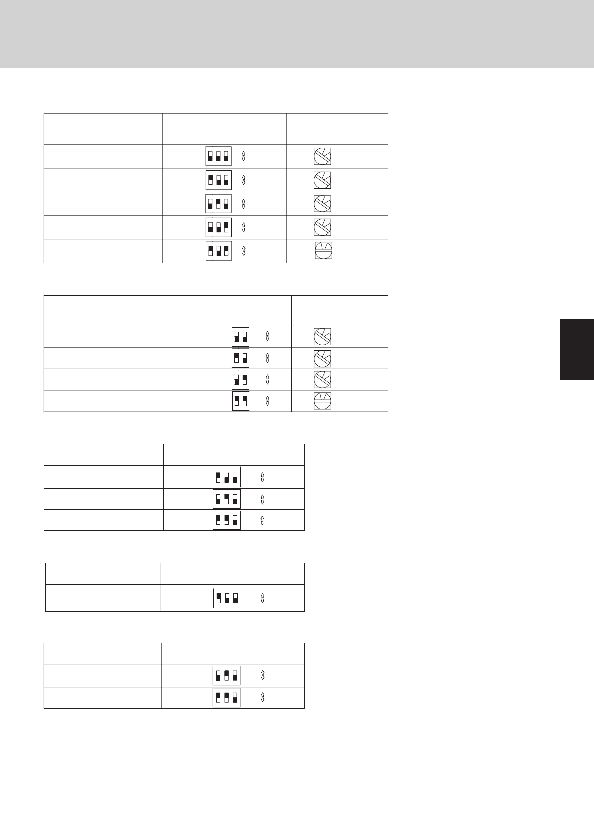
Examples of the No. of indoor units settings (S005, S004)
z
No. of indoor units
1 unit (factory setting)
11 units
21 units
31 units
40 units
Examples of refrigerant circuit (R.C.) address settings (required when link wiring is used) (S003, S002)
z
Indoor unit setting (S005)
(3P DIP switch, blue)
All OFF
1 ON
2 ON
3 ON
1 & 3 ON
10 20 30
ON
1
ON
1
ON
1
ON
1
ON
1
ON
3
2
OFF
ON
3
2
OFF
ON
3
2
OFF
ON
3
2
OFF
ON
3
2
OFF
System address (S003)
System address No.
System 1 (factory setting)
System 11
System 21
System 30
(2P DIP switch, blue)
10 20
1 ON
2 ON
ON
2
1
ON
2
1
ON
2
1
ON
2
1
Both OFF
1 & 2 ON
Indoor unit setting (S004)
(Rotary switch, red)
1
1
1
1
0
System address (S002)
(Rotary switch, black)
ON
OFF
ON
OFF
ON
OFF
ON
OFF
1
1
1
0
Set to 1
Set to 1
Set to 1
Set to 1
Set to 0
Set to 1
Set to 1
Set to 1
Set to 0
Test Run
1
2
Examples of the No. of outdoor units settings (S006)
z
No. of outdoor units
1 unit (factory setting)
2 units
3 units
Address setting of main outdoor unit (S007)
z
Unit No. setting
Outdoor unit setting (S006)
(3P DIP switch, blue)
ON
1 ON
2 ON
1 & 2 ON
1
ON
12
ON
1
2
2
Address setting of outdoor unit (S007)
(3P DIP switch, blue)
Unit No. 1 (main unit)
(factory setting)
Address setting of sub outdoor unit
z
Unit No. setting
Unit No. 2 (sub unit)
(factory setting)
Unit No. 3 (sub unit)
Address setting of outdoor unit (S007)
(3P DIP switch, blue)
2 ON
1 & 2 ON
ON
12
ON
21ON3
21
ON
3
OFF
ON
3
OFF
ON
3
OFF
3
4
ON
OFF
5
ON
3
OFF
ON
3
OFF
6
The sub unit control PCB contains the same switches as the main unit control PCB for No. of indoor units, No. of outdoor units,
and system address. However it is not necessary to set these switches.
1-5
7
8
Page 10
3. Auto Address Setting
1. Auto Address Setting
Test Run
1
2
3
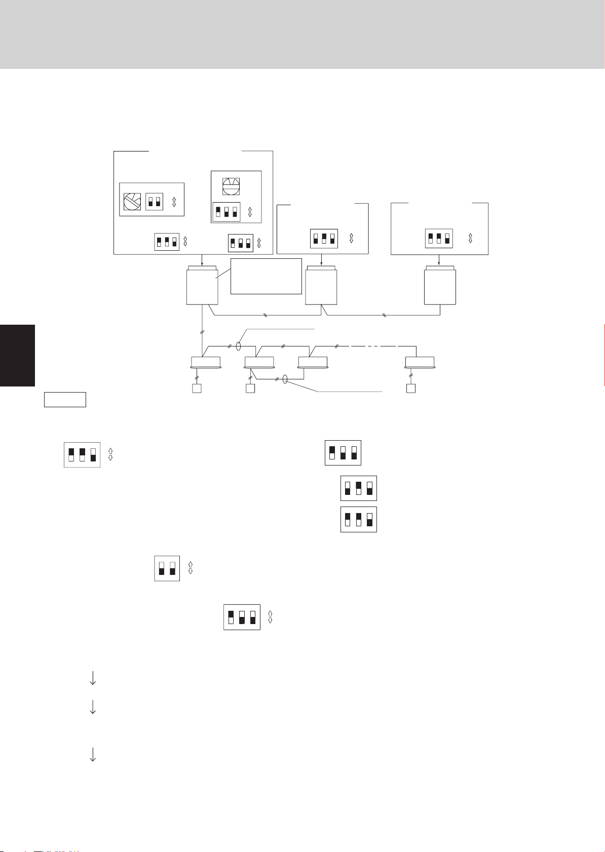
Basic wiring diagram: Example (1)
• If link wiring is not used
(The inter-unit control wires are not connected to multiple refrigerant systems.)
Indoor unit addresses can be set without operating the compressors.
No. 1 (main outdoor unit)
settings
System address
(system 1 setting)
(S003)(S002)
ON
1
No. of
outdoor
units (3 units
setting)
ON
2
1
OFF
(S006) (S007)
ON
ON
2
3
1
OFF
Outdoor Unit
Indoor Unit
Remote controller
Case 1
(1) Automatic Address Setting from the Outdoor Unit
1. To set the number of outdoor units, on the outdoor main unit control PCB set the No. of outdoor units DIP switch (S006) to
ON
123
ON
(3 units), and set the unit No. DIP switch (S007) to
OFF
2. On the No. 2 (sub) unit control PCB, set the unit No. switch (S007) to
On the No. 3 (sub) unit control PCB, set the unit No. switch (S007) to
No. of indoor units
(10 units setting)
(S005)
1ON3
Unit number
setting
(Unit No. 1)
Unit
No. 1
(Main)
1-1
(S004)
0
ON
2
OFF
ON
1
2
3
OFF
ON
Unit
number
setting
(Unit No. 2)
Leave the socket that
is used to short-circuit
the terminal plug.
(CN003)
Outdoor main/sub
control wiring
Inter-unit control wiring
1-2 1-3
No. 2 (sub unit)
(S007)
ON
123
Unit
No. 2
(Sub)
Remote controller
cross-over wiring
ON
2
1
ON
ON
No. 3 (sub unit)
ON
OFF
Unit
number
setting
(Unit No. 3)
ON
(S007)
1
2
3
Unit
No. 3
Outdoor main/sub
(Sub)
control wiring
1-10
(unit No. 1 - main outdoor unit).
3
(unit No. 2).
3
2
1
(unit No. 3).
123
ON
OFF
4
5
6
7
8
3. On the outdoor main unit control PCB, check that the system address rotary switch (S002) is set to “1” and that the DIP
ON
switch (S003) is set to
ON
1
“0.” (These are the settings at the time of factory shipment.)
2
OFF
4. To set the number of indoor units that are connected to the outdoor unit to 10, on the outdoor main unit control PCB set the
ON
2
“1.” and set the rotary switch (S004) to “0.”
3
OFF
No. of indoor units DIP switch (S005) to
ON
1
5. Turn ON the power to the indoor and outdoor units.
6. On the outdoor main unit control PCB, short-circuit the automatic address pin (CN100) for 1 second or longer, then release i t.
(Communication for automatic address setting begins.)
* To cancel, again short-circuit the automatic address pin (CN100) for 1 second or longer, then release it.
The LED that indicates that automatic address setting is in progress turns OFF and the process is stopped.
Be sure to perform automatic address setting again.
(Automatic address setting is completed when LEDs 1 and 2 on the outdoor main unit control PCB turn OFF.)
7. Operation from the remote controllers is now possible.
* To perform automatic address setting from the remote controller, perform steps 1 to 5, then use the remote controller and
complete automatic address setting.
Refer to “Automatic Address Setting from the Remote Controller.”
z
1-6
Page 11
3. Auto Address Setting
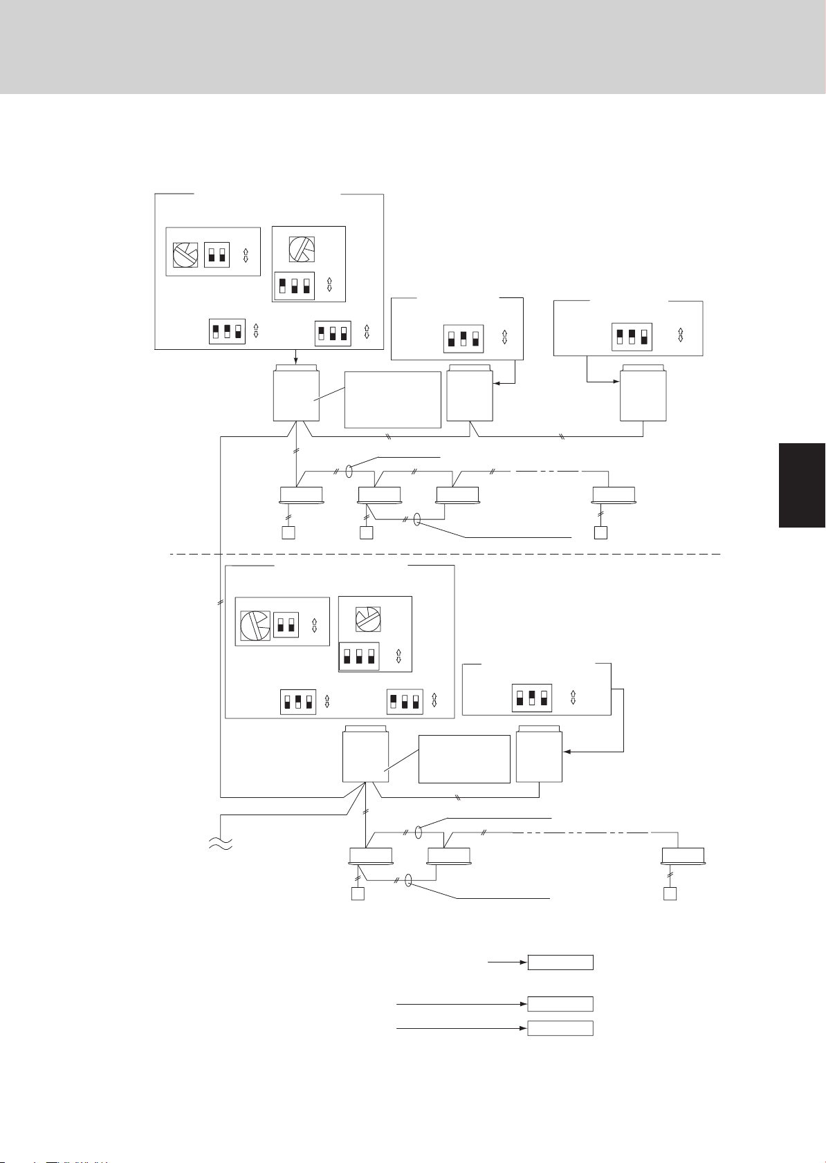
Basic wiring diagram: Example (2)
Test Run
No. 1 (main outdoor unit) settings
System address
(system 1 setting)
1
No. of
outdoor units
(3 units
setting)
No. 2
Refrigerant
circuit
(S003)(S002)
ON
ON
2
1
OFF
(S006)
ON
2
3
1
Outdoor unit
system 1
Indoor unit
Remote
controller
No. of
outdoor
units (2 units
setting)
• If link wiring is used
No. of indoor units
(13 units setting)
(S004)
(S005)
ON
3
2
1
Unit
ON
number
setting
(unit No. 1)
OFF
Unit
No. 1
(Main)
1-1 1-2
No. 1 (main unit) settings
System address
(system 2 setting)
(S003)(S002)
ON
ON
2
1
2
OFF
(S006)
ON
123
ON
OFF
(S007)
ON
ON
2
3
1
OFF
Leave the socket that
is used to short-circuit
the terminal plug.
(CN003)
No. of indoor units
(9 units setting)
(S004)
9
(S005)
2
1ON3
Unit
ON
number
setting
(unit No. 1)
OFF
* When multiple outdoor main units exist, remove the socket that is
used to short-circuit the terminal plug (CN003) from all outdoor
main unit PCBs except for one unit.
Alternatively, move the sockets to the “OPEN” side.
No. 2 (sub unit)
Unit
number
setting
(unit No. 2)
(S007)
ON
123
Unit
No. 2
(Sub)
Inter-unit control wiring
1-3 1-13
Remote controller
communication wiring
ON
OFF
(S007)
ON
1
2
3
ON
OFF
Unit
number
setting
(unit No. 2)
Unit
ON
OFF
number
setting
(unit No. 3)
Outdoor main/sub
control wiring
No. 2 (sub unit) settings
(S007)
ON
123
ON
OFF
No. 3 (sub unit)
(S007)
ON
3
2
1
Unit
No. 3
(Sub)
ON
OFF
1
2
3
Outdoor unit
system 2
Unit
No. 1
(Main)
Move the socket to
the
“
OPEN” side
(CN003).
Inter-unit control wiring
To other system
link wiring
Indoor unit
Remote
controller
2-1 2-2 2-9
Remote controller
cross-over wiring
Make settings as appropriate for the cases listed below.
(Refer to the instructions on the following pages.)
· Indoor and outdoor unit power can be turned ON for each system separately.
· Indoor and outdoor unit power cannot be turned ON for each system separately.
Automatic address setting in Heating mode
Automatic address setting in Cooling mode
1-7
Unit
No. 2
(Sub)
Outdoor main/sub control wiring
Case 2
Case 3A
Case 3B
4
5
6
7
8
Page 12

3. Auto Address Setting
Case 2 Automatic Address Setting (no compressor operation)
Indoor and outdoor unit power can be turned ON for each system separately.
z
Indoor unit addresses can be set without operating the compressors.
Automatic Address Setting from Outdoor Unit
1. On the No. 1 (main) unit control PCB, set the unit No. switch (S007) to
On the No. 2 (sub) unit control PCB, set the unit No. switch (S007) to
On the No. 3 (sub) unit control PCB, set the unit No. switch (S007) to
ON
ON
Test Run
ON
(unit No. 1).
2
3
1
(unit No. 2).
3
2
1
(unit No. 3).
3
2
1
1
2
3
4
2. To set the number of outdoor units on the outdoor main unit control PCB, set the No. of outdoor units DIP switch (S006) to
ON
123
3. On the outdoor main unit control PCB, check that the system address rotary switch (S002) is set to “1” and that the DIP
switch (S003) is set to “0”
4. To set the number of indoor units that are connected to the outdoor unit to 13, on the outdoor main unit control PCB set the
No. of indoor units DIP switch (S005) to “1”
5. Turn on power to all indoor and outdoor units in the system.
6. Short-circuit the automatic address pin at the outdoor main unit (CN100) for 1 second or longer, then release it.
(Communication for automatic address setting begins.)
(Automatic address setting is completed when LEDs 1 and 2 on the outdoor main unit control PCB turn OFF.)
ON
(3 units).
OFF
ON
ON
1
* To cancel, again short-circuit the automatic address pin (CN100) for 1 second or longer, then release it.
The LED that indicates automatic address setting is in progress turns OFF and the process is stopped. Be
sure to perform automatic address setting again.
. (These are the settings at the time of factory shipment.)
2
OFF
ON
1
ON
2
, and set the rotary switch (S004) to “3.”
3
OFF
5
6
7
8
7. Next turn the power ON only for the indoor and outdoor units of the next (different) system. Repeat steps 1 - 5 in the same
way to complete automatic address settings for all systems.
8. Operation from the remote controllers is now possible.
* To perform automatic address setting from the remote controller, perform steps 1 - 5, then use the remote controller and
complete automatic address setting.
Refer to “Automatic Address Setting from Remote Controller.”
z
1-8
Page 13

3. Auto Address Setting
Case 3A Automatic Address Setting in Heating Mode
Indoor and outdoor unit power cannot be turned ON for each system separately.
z
In the following, automatic setting of indoor unit addresses is not possible if the compressors are not operating.
Therefore perform this process only after completing all refrigerant tubing work.
Automatic Address Setting from Outdoor Unit
Test Run
1. Perform steps 1 - 4 in the same way as for
5. Turn the indoor and outdoor unit power ON at all systems.
6. To perform automatic address setting in Heating mode , on the outdoor main unit control PCB in the refrigerant system
where you wish to set the addresses, short-circuit the automatic address pin (CN100) for 1 second or longer, then release
it. (Be sure to perform this process for one system at a time. Automatic address settings cannot be performed for more than
one system at the same time.)
(Communication for automatic address setting begins, the compressors turn ON, and automatic address setting in Heating
mode begins.)
(All indoor units operate.)
* To cancel, again short-circuit the automatic address pin (CN100) for 1 second or longer, then release it. The
LED that indicates automatic address setting is in progress turns OFF and the process is stopped. Be sure to
perform automatic address setting again.
(Automatic address setting is completed when the compressors stop and LED 1 and 2 on the main unit control PCB turn
OFF.)
7. At the outdoor main unit in the next (different) system, short-circuit the automatic address pin (CN100) for 1 second or
longer, then release it.
(Repeat the same steps to complete automatic address setting for all units.)
8. Operation from the remote controllers is now possible.
* To perform automatic address setting from the remote controller, perform steps 1 - 5, then use the remote controller and
to complete automatic address setting.
Case 2
.
1
2
3
Refer to “Automatic Address Setting from Remote Controller.”
z
4
5
6
7
1-9
8
Page 14
3. Auto Address Setting
Case 3B Automatic Address Setting in Cooling Mode
Indoor and outdoor unit power cannot be turned ON for each system separately. In the following, automatic setting of indoor
z
unit addresses is not possible if the compressors are not operating. Therefore perform this process only after completing all
refrigerant tubing work.
Automatic address setting can be performed during Cooling operation.
Automatic Address Setting from Outdoor Unit
Test Run
1
2
3
1. Perform steps 1 - 4 in the same way as for
5. Turn the indoor and outdoor unit power ON at all systems.
6. To perform automatic address setting in Cooling mode , on the outdoor main unit control PCB in the refrigerant system
where you wish to set the addresses, short-circuit the mode change 2P pin (CN101). At the same time, short-circuit the
automatic address pin (CN100) for 1 second or longer, then release it. (Be sure to perform this process for one system at a
time. Automatic address settings cannot be performed for more than one system at the same time.)
(Communication for automatic address setting begins, the compressors turn ON, and automatic address setting in Cooling
mode begins.)
(All indoor units operate.)
* To cancel, again short-circuit the automatic address pin (CN100) for 1 second or longer, then release it. The
LED that indicates automatic address setting is in progress turns OFF and the process is stopped. Be sure to
perform automatic address setting again.
(Automatic address setting is completed when the compressors stop and LED 1 and 2 on the outdoor main unit control PCB
turn OFF.)
7. At the outdoor main unit in the next (different) system, short-circuit the automatic address pin (CN100) for 1 second or
longer, then release it.
(Repeat the same steps to complete automatic address setting for all units.)
8. Operation from the remote controllers is now possible.
* Automatic address setting in Cooling mode cannot be done from the remote controller.
Case 2
.
4
5
6
7
8
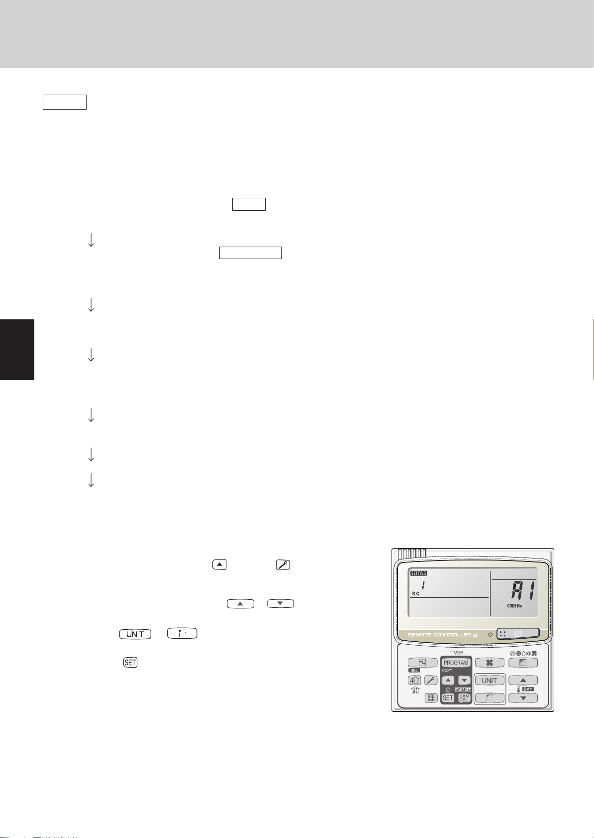
Automatic Address Setting* from the Remote Controller
Selecting each refrigerant system individually for automatic address setting
---Automatic address setting for each system: Item code “A1.”
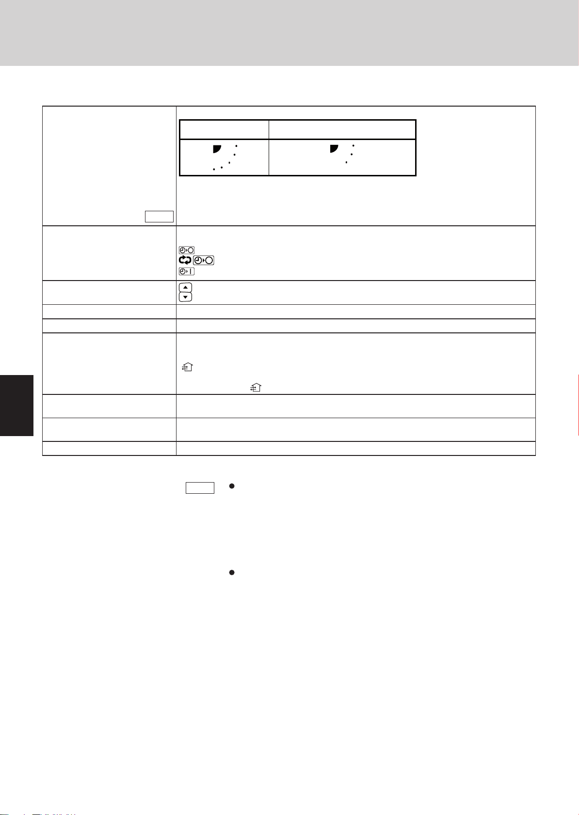
1. Press the remote controller timer time
time.
(Press and hold for 4 seconds or longer.)
2. Next, press either the temperature setting
the item code is “A1.”)
3. Use either the
matic address setting.
4. Then press the
(Automatic address setting for one refrigerant system begins.)
(When automatic address setting for one system is completed, the system returns
to normal stopped status.) <Approximately 4 - 5 minutes is required.>
(During automatic address setting, “NOW SETTING” is displayed on the remote
controller. This message disappears when automatic address setting is completed.)
5. Repeat the same steps to perform automatic address setting for each successive system.
or button to set the system No. to perform auto-
button.
button and button at the same
or button. (Check that
1-10
Page 15
Test Run
y
3. Auto Address Setting
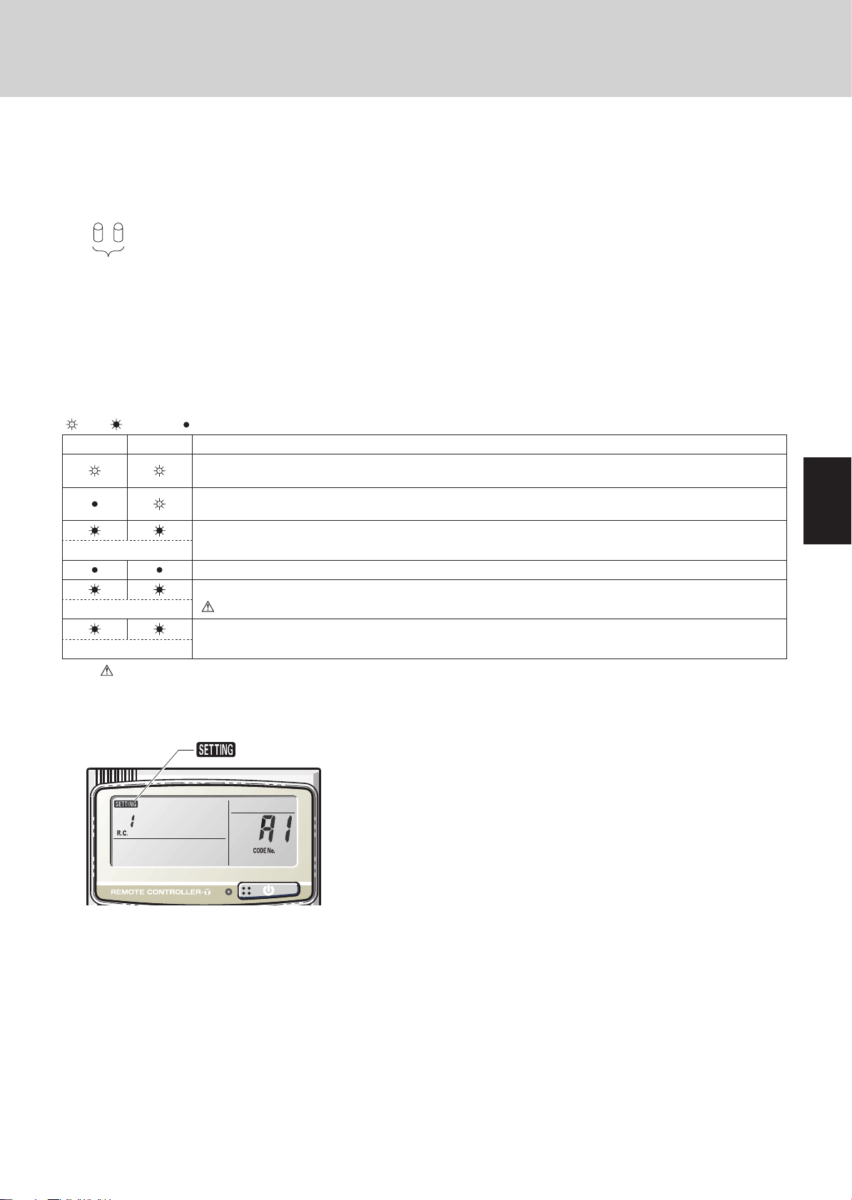
Display during automatic address setting
On outdoor main unit PCB
z
1
2
LED
* Do not short-circuit the automatic address setting pin (CN100) again while automatic address setting is in
progress. Doing so will cancel the setting operation and will cause LED 1 and 2 to turn OFF.
Blink alternatel
* When automatic address setting has been successfully completed, both LED 1 and 2 turn OFF.
* LED 1 is D72. LED 2 is D75.
* If automatic address setting is not completed successfully, refer to the table below and correct the problem. Then perform
automatic address setting again.
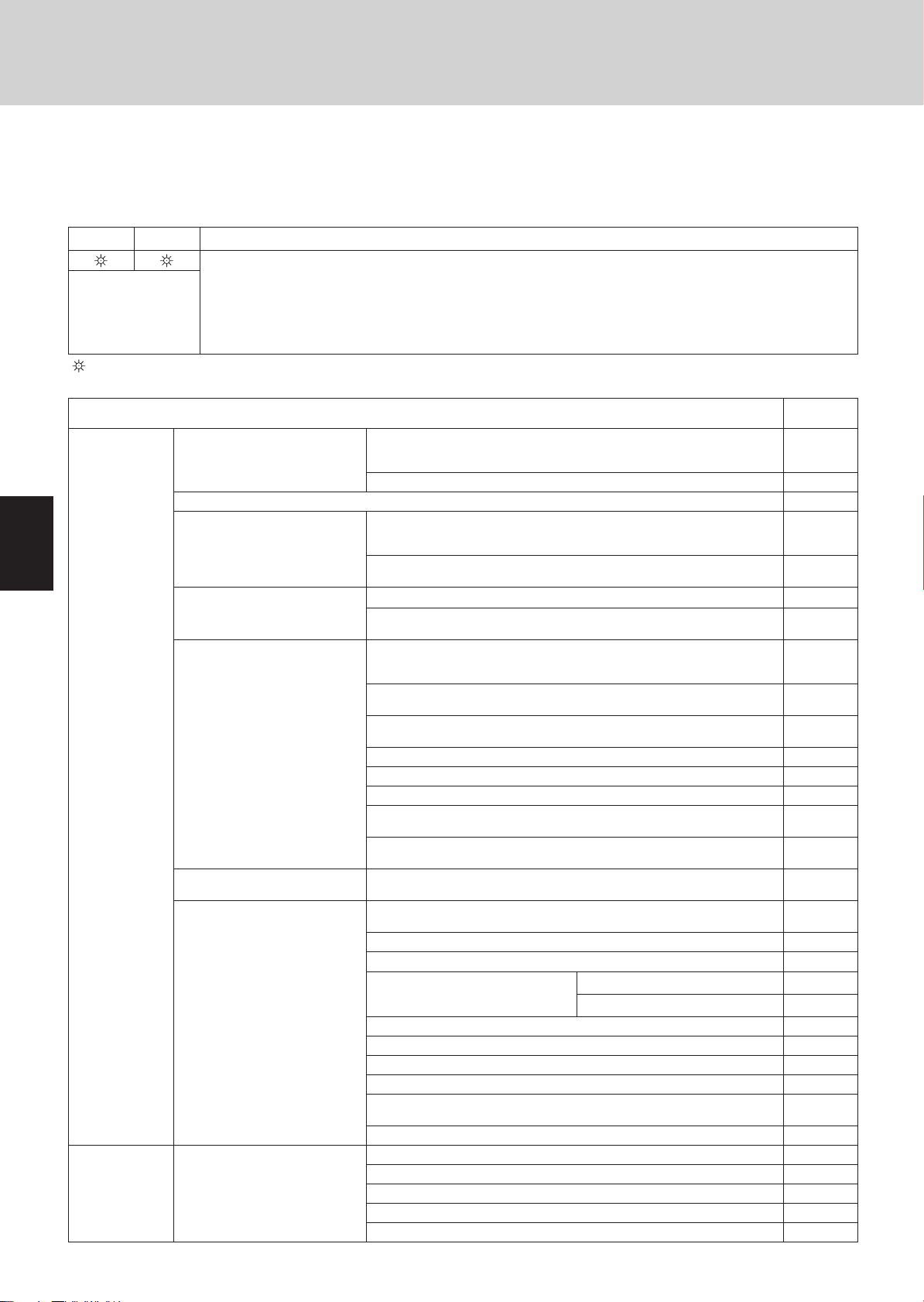
Display of LED 1 and 2 on the outdoor unit control PCB
z
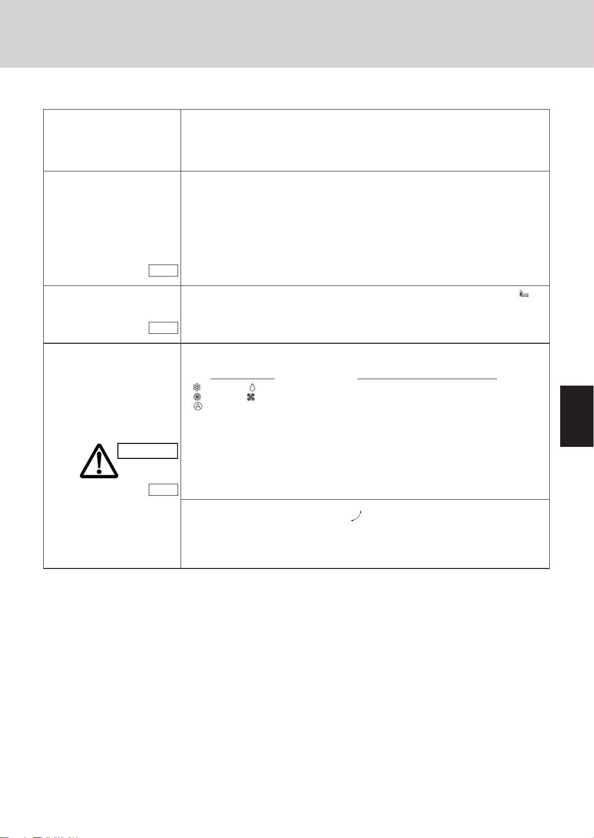
( : ON : Blinking :OFF)
LED1 LED2 Display meaning
After the power is turned ON (and automatic address setting is not in progress), no communication with the indoor
units in that system is possible.
After the power is turned ON (and automatic address setting is not in progress), 1 or more indoor units are
confi rmed in that system; however, the number of indoor units does not match the number that was set.
1
Alternating
Simultaneous
Alternating
Note: “ ” indicates that the solenoid is fused or that there is a CT detection current failure (current is detected when the com-
pressor is OFF).
Remote controller display
z
Automatic address setting is in progress.
Automatic address setting completed.
At time of automatic address setting, the number of indoor units did not match the number that was set.
“ ”(when indoor units are operating) indication appears on the display.
Refer to “Table of Self-Diagnostic Functions and Description of Alarm Displays.”
is blinking
2
3
4
5
6
7
1-11
8
Page 16
1
Test Run
3. Auto Address Setting
4. Remote Controller Test Run Settings
Request concerning recording the indoor/outdoor unit combination Nos.
After automatic address setting has been completed, be sure to record them for future reference.
List the outdoor main unit system address and the addresses of the indoor units in that system in an easily visible location (next
to the nameplate), using a permanent marking pen or similar means that cannot be abraded easily.
Example: (Outdoor) 1 - (Indoor) 1-1, 1-2, 1-3… (Outdoor) 2 - (Indoor) 2-1, 2-2, 2-3…
These numbers are necessary for later maintenance. Please be sure to indicate them.
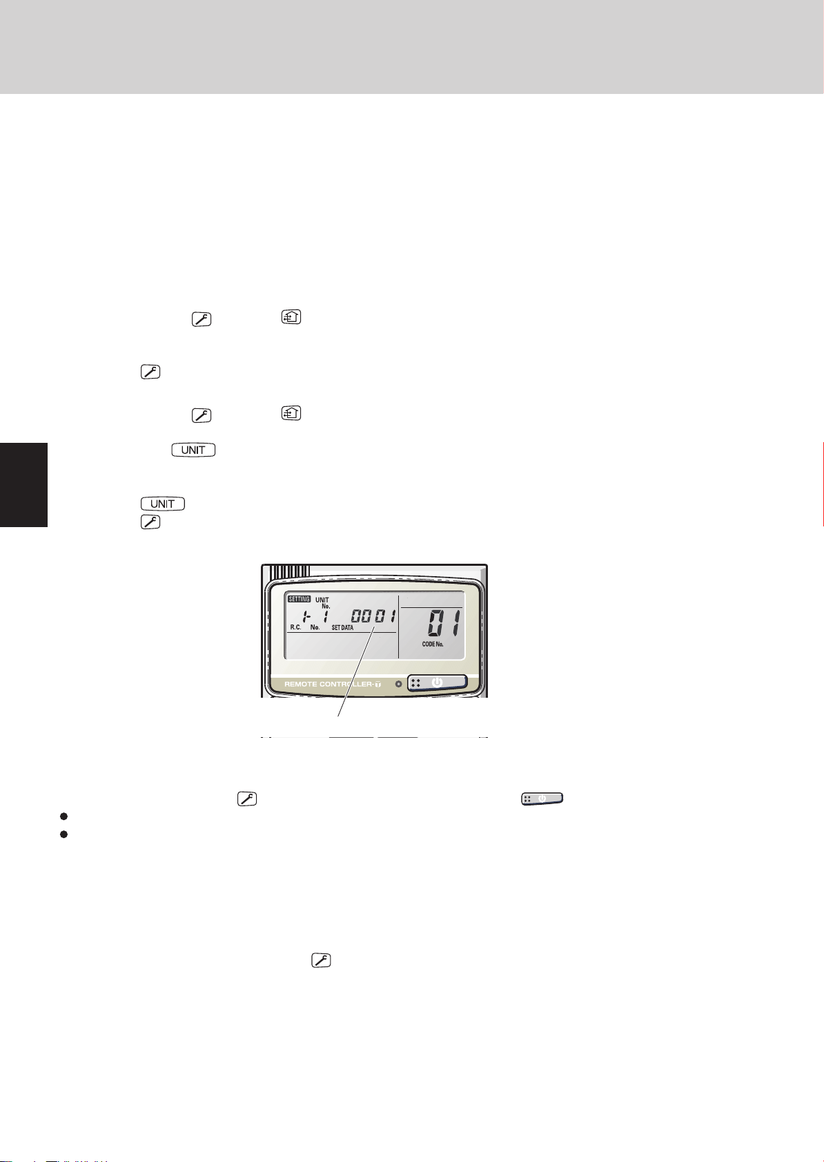
Checking the indoor unit addresses
Use the remote controller to check the indoor unit address.
<If 1 indoor unit is connected to 1 remote controller>
1. Press and hold the button and button for 4 seconds or longer (simple settings mode).
2. The address is displayed for the indoor unit that is connected to the remote controller.
(Only the address of the indoor unit that is connected to the remote controller can be checked.)
3. Press the
<If multiple indoor units are connected to 1 remote controller (group control)>
1. Press and hold the button and button for 4 seconds or longer (simple settings mode).
2. “ALL” is displayed on the remote controller.
3. Next, press the
4. The address is displayed for 1 of the indoor units which is connected to the remote controller. Check that the fan of that
indoor unit starts and that air is discharged.
5. Press the
6. Press the
button again to return to normal remote controller mode.
button.
button again and check the address of each indoor unit in sequence.
button again to return to normal remote controller mode.
2
3
4
5
6
Number changes to indicate which indoor unit is currently selected.
4. Remote Controller Test Run Settings
1. Press the remote controller button for 4 seconds or longer. Then press the button.
“TEST RUN” appears on the LCD display while the test run is in progress.
The temperature cannot be adjusted when in Test Run mode.
(This mode places a heavy load on the machines. Therefore use it only when performing the test run.)
2. The test run can be performed using the HEAT, COOL, or FAN operation modes.
Note: The outdoor units will not operate for approximately 3 minutes after the power is turned ON and after operation is
stopped.
3. If correct operation is not possible, a code is displayed on the remote controller LCD display.
(Refer to “Table of Self-Diagnostic Functions” and correct the problem.)
4. After the test run is completed, press the
prevent continuous test runs, this remote controller includes a timer function that cancels the test run after 60 minutes.)
* If the test run is performed using the wired remote controller, operation is possible even if the cassette-type ceiling panel has
not been installed. (“P09” display does not occur.)
button again. Check that “TEST RUN” disappears from the LCD display. (To
7
8
1-12
Page 17

Test Run
5. Caution for Pump Down
5. Caution for Pump Down
Pump down means refrigerant gas in the system is returned to the outdoor unit. Pump down is used when the unit is to be
moved, or before servicing the refrigerant circuit.
This outdoor unit cannot collect more
CAUTION
than the rated refrigerant amount as
shown by the nameplate on the back.
If the amount of refrigerant is more
than that recommended, do not
conduct pump down. In this case use
another refrigerant collecting system.
1
2
3
4
5
1-13
6
7
8
Page 18
1
2
3
4
5
6
7
8
Test Run
6. Meaning of Alarm Messages
6. Meaning of Alarm Messages
Table of Self-Diagnostics Functions and Description of Alarm Displays
Alarm messages are indicated by the blinking of LED 1 and 2 (D72, D75) on the outdoor unit PCB. They are also displayed on
the wired remote controller.
Viewing the LED 1 and 2 (D72 and D75) alarm displays
z
LED1 LED2 Alarm contents
Alarm Display
Alternating
(
: Blinling) Connect the outdoor maintenance remote controller to the RC socket on the outdoor main unit control PCB (3P,
blue),and check the Alarm Messages on the remote controller display.
Possible cause of malfunction
Serial
communication
errors
Mis-setting
Activation of
protective
device
Remote controller is detecting
error signal from indoor unit.
Indoor unit is detecting error signal from remote controller (and system controller). <<E03>>
Indoor unit is detecting error
signal from main outdoor unit.
Improper setting of indoor unit
or remote controller.
During auto address setting,
number of connected units does
not correspond to number set.
When turning on the power
supply, number of connected
units does not correspond to
number set.
(Except R.C. address is "0.")
Indoor unit communication error
of group control wiring.
Improper setting. This alarm message shows when an indoor unit for multiple-useis not
Protective device in indoor unit
is activated.
LED 1 blinks M times, then LED 2 blinks N times. The cycle then repeats.
M = 2: P alarm 3: H alarm 4: E alarm 5: F alarm 6: L alarm
N = Alarm No.
Example: LED 1 blinks 2 times, then LED 2 blinks 17 times. The cycle then repeats.
Alarm is "P17".
Error in receiving serial communication signal.
(Signal from main indoor unit in case of group control)
Ex: Auto address is not completed.
Error in transmitting serial communication signal. <E02>
Error in receiving serial communication signal.
When turning on the power supply, the number of connected indoor units
does not correspond to the number set. (Except R.C. address is "0.")
Error of the main outddor unit in receiving serial communication signal
from the indoor unit.
Indoor unit address setting is duplicated.
Remote controller adress connector (RCU. ADR) is duplicated.
(Duplication of main remote controller)
Starting auto address setting is prohibited.
This alarm message shows that the auto address connector CN100 is
shorted while other RC line is executing auto address operation.
Error in auto address setting. (Number of connected indoor units is less
than the number set.)
Error in auto address setting. (Number of connected indoor units is more
than the number set.)
No indoor unit is connected during auto address setting. E20
Main outdoor unit is detecting error signal from sub outdoor unit. E24
Error of outdoor unit address setting. E25
The number of connected main and sub outdoor units do not correspond
to the number set at main outdoor unit PCB.
Error of sub outdoor unit in receiving serial communication signal from
main outdoor unit.
Error of main indoor unit in receiving serial communication signal from
sub indoor units.
connected to the outdoor unit.
Duplication of main indoor unit address setting in group control. <L03>
Duplication of outdoor R.C. address setting. L04
There are 2 or more indoor unit
controllers that have oparation
mode priority in refrigerant circuit.
Group control wiring is connected to individual control indoor unit. L07
Indoor unit address is not set. L08
Capacity code of indoor unit is not set. <<L09>>
Capacity code of outdoor unit is not set. L10
Mis-matched connection of outdoor units that have different kinds of
refrigerant.
4-way valve operation failure L18
Thermal protector in indoor unit fan motor is activated. <<P01>>
Improper wiring connections of ceiling panel. <<P09>>
Float switch is activated. <<P10>>
Operation of protective function of fan inverter. P12
2
sensor (detects low oxygen level) activated. P14
O
Priority set remote controller L05
Non-priority set remote controller L06
1-14
Alarm
Message
<E01>
E04
<E06>
E08
<<E09>>
E12
E15
E16
E26
E29
E18
L02
L17
Continued
Page 19
6. Meaning of Alarm Messages
Test Run
Possible cause of malfunction
Activation of
protective
device
Thermistor fault Indoor thermistor is either open
EEP ROM on indoor unit PCB failure F29
Protective
device for
compressor is
activated
Protective device in outdoor unit
is activated.
or damaged.
Outdoor thermistor is either
open or damaged.
Protective device for
compressor No.1 is activated.
Protective device for
compressor No.2 is activated
Protective device for
compressor No.3 is activated.
Low oil level. H07
Oil sensor fault.
(Disconnection, etc.)
Compressor therminal protector is activated.
Power supply voltage is unusual. (The voltage is more than 260 V or less
than 160 V between L1 and L2 phase.)
Incorrect discharge temperature. (Comp. No. 1) P03
High pressure switch is activated. P04
Negtive (defective) phase. P05
Compressor running failure resulting from missing phase in the
compressor wiring, etc. (Start failure not caused by IPM or no gas.)
Incorrect discharge temperature. (Comp. No. 2) P17
Compressor 3 discharge temp. failure P18
Outdoor unit fan motor is unusual. P22
Overcurrent at time of compressor runs more than 80Hz (DCCT
secondary current or ACCT primary current is detected at a time other
than when IPM has tripped.)
IPM trip (IPM current or temperature) H31
Inverter for compressor is unusual. (DC compressor does not operate.) P29
Indoor coil temp. sensor (E1) <<F01>>
Indoor coil temp. sensor (E2) <<F02>>
Indoor coil temp. sensor (E3) <<F03>>
Indoor suction air (room) temp. sensor (TA) <<F10>>
Indoor discharge air temp. sensor (BL) <<F11>>
Comp. No. 1 discharge gas temp. sensor (DISCH1) F04
Comp. No. 2 discharge gas temp. sensor (DISCH2) F05
Outdoor No. 1 coil gas temp. sensor (EXG1) F06
Outdoor No. 1 coil liquid temp. sensor (EXL1) F07
Outdoor air temp. sensor (AIR TEMP) F08
Compressor intake port temperature sensor (RDT) F12
High pressure sensor. Negative (defective) N phase.
Low-pressure sensor failure F17
Compressor 3 discharge temp. sensor failure (DISCH3) F22
Outdoor No. 2 coil gas temp. sensor (EXG2) F23
Outdoor No. 2 coil liquid temp. sensor (EXL2) F24
EEP ROM on the main or sub outdoor unit PCB has failed. F31
Current is not detected when comp. No. 1 is ON. H03
Discharge gas temperature of the comp. No. 1 is not detected.
Temp. sensor is not seated at the sensor holder.
Overload current is detected. H11
Lock current is detected. H12
Current is not detected when comp. No.2 is ON. H13
Discharge gas temperture of comp. No.2 is not detected. H15
Compressor No.3 current trouble (overcurrent) H21
Compressor No.3 current trouble (locked) H22
Compressor No.3 CT sensor disconnected or short circuit H23
Compressor No.3 discharge temp. sensor disconnected H25
Low pressure switch is activated. H06
Comp. No.1 oil sensor H08
Comp. No.2 oil sensor H27
Oil sensor (connection) failure H28
Alarm
Message
P02
P16
P26
F16
H05
Continued
1
2
3
4
5
6
7
1-15
8
Page 20

6. Meaning of Alarm Messages
Alarm messages displayed on system controller
Serial
communication
errors
Mis-setting
Activation of
protective
device
NOTE
1. Alarm messages in << >> do not affect other indoor unit operations.
2. Alarm messages in < > sometimes affect other indoor unit operations depending on the fault.
Error in transmitting serial
communication signal
Error in receiving serial
communication signal
Protective device of sub indoor
unit in group control is activated
Indoor or main outdoor unit is not oparating correctly.
Mis-wiring of control wiring between indoor unit, main outdoor unit and
system controller.
Indoor or main outdoor unit is not operating correctly.
Mis-wiring of control wiring between indoor unit, main outdoor unit and
system controller.CN1 is not connected properly.
When using wireless remote controller or system controller, in order to
check the alarm message in detail, connect wired remote controller to
indoor unit temporarily.
Test Run
C05
C06
P30
1
2
3
4
5
6
7
8
1-16
Page 21

Remote Control Functions
Contents
2. REMOTE CONTROL FUNCTIONS
1.Main Operating Functions ..................................................................................................2-2
1. Room Temperature Control ..............................................................................................2-2
2. Automatic Control for Heating and Cooling ......................................................................2-3
2.Wireless Remote Controller ...............................................................................................2-4
1. How to Use the Wireless Remote Controller ....................................................................2-4
2. Receiver ...........................................................................................................................2-7
3. Operation ..........................................................................................................................2-8
4. Using the Wireless Remote Control Unit ..........................................................................2-9
5. Address Settings ............................................................................................................2-10
6. Emergency Operation .....................................................................................................2-12
7. Troubleshooting ..............................................................................................................2-14
3. Timer Remote Controller (RCS-TM80BG) ......................................................................2-15
1. How to Use the Timer Remote Controller .......................................................................2-15
2. Names and Operations ...................................................................................................2-16
3. Installation Manual for Timer Remote Controller ............................................................2-18
4. How to Install the Remote Controller ..............................................................................2-18
5. Group Control Using 2 Remote Controllers ....................................................................2-19
6. Remote Controller Setting Mode ....................................................................................2-19
7. Indoor Unit Setting Mode ................................................................................................2-19
8. To Display the Sensor Temperature ................................................................................2-19
9. To Display the Trouble History ........................................................................................2-19
10. Setting the Present Time ..............................................................................................2-21
11. Weekly Program Function ............................................................................................2-22
12. Outing Function ............................................................................................................2-27
13. Sleeping Function .........................................................................................................2-29
14. Wired Remote Controller Test Run Setting ...................................................................2-30
15. Simple Settings Function ..............................................................................................2-31
16. Detailed Settings Function............................................................................................2-33
17. Remote Controller Servicing Functions ........................................................................2-40
1
1
2
2
3
3
4
4
2-1
5
5
6
6
7
7
8
8
Page 22
Remote Control Functions
1. Main Operating Functions
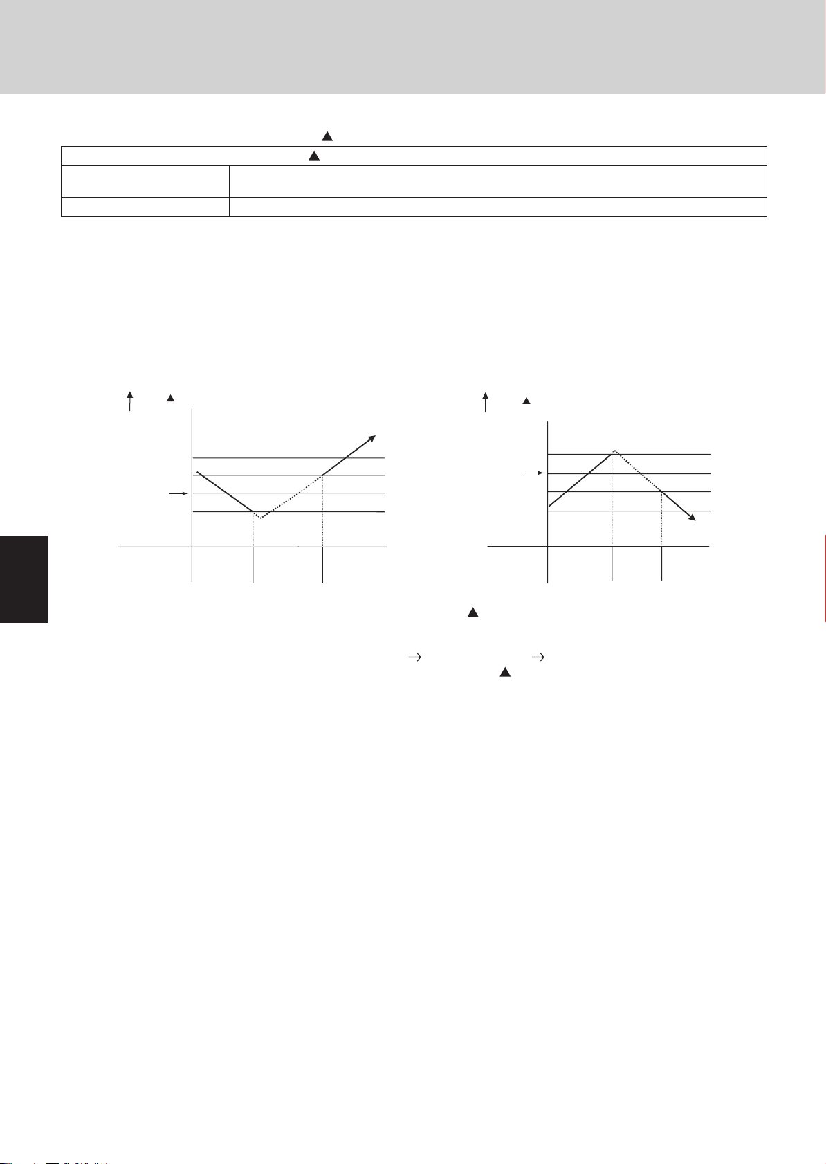
1. Room Temperature Control
The thermostat is turned ON/OFF according to as shown below.
T = Room temperature - Set temperature
When remote controller sensor
is used
When body sensor is used Room temperature = Temperature detected by the body sensor - Intake shift temperature*
* Intake shift temperature (enabled only during heating)
During heating, a difference in temperature occurs between the top and bottom of a room. This value is set in consideration for
the difference between the temperature detected by the body sensor and the temperature at the bottom of the room.
<Value set for intake shift temperature at time of shipment>: 39°F (4°C)
Note: The shift temperature can be selected in the range of 32 – 50°F (0 – 10°C), by using the remote controller simplifi ed set-
ting mode.
Room temperature = Temperature detected by the remote controller sensor
1
1
2
2
3
3
4
4
Cooling
T
Room temperature
(deg)
+4
+2
Set temperature
–2
Thermostat
(1) After the thermostat turns ON, it will not turn OFF again as a result of for 5 minutes.
(2) After the thermostat turns OFF, it will not turn ON again for 3 minutes. (It also will not turn ON for 3 minutes after the power
is switched ON.)
(3) The compressor turns OFF if the mode is changed cooling heating (or heating cooling) while the compressor is ON.
(4) If “test run” mode is selected, the thermostat will not turn OFF as a result of for 60 minutes. (The thermostat is forced ON.)
ON ONOFF
Room temperature
Set temperature
Thermostat
T
(deg)
+2
–2
–4
Heating
ON ONOFF
5
5
6
6
7
7
8
8
2-2
Page 23
Remote Control Functions
g
g
g
1. Main Operating Functions
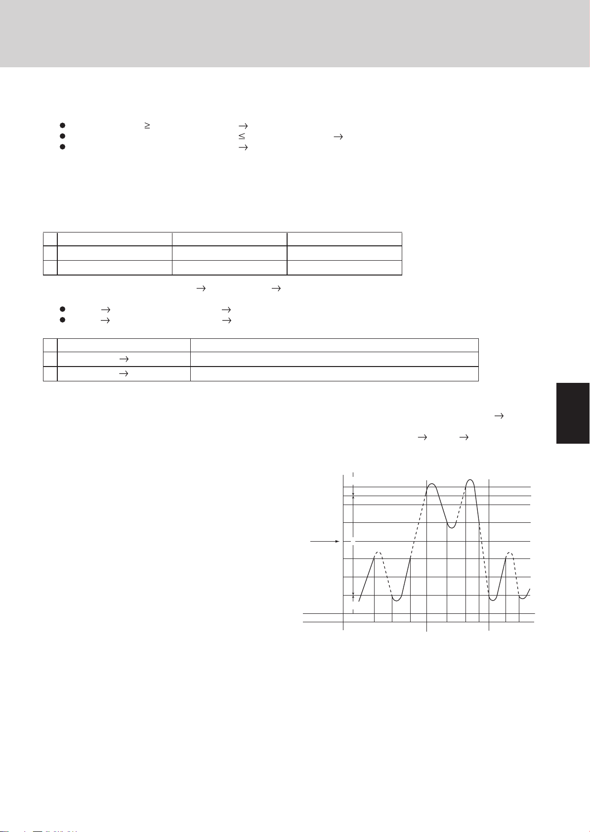
2. Automatic Control for Heating and Cooling
Automatic Heating/Cooling Control
(1) When operation starts, heating or cooling is selected according to the set temperature and the room temperature.
Room temperature
Set temperature – 2F < Room temperature Set temperature + 2F Monitoring mode (*1)
Room temperature < Set temperature – 2F Heating
*1: If the difference between the room temperature and set temperature is small when operation starts, the cooling
thermostat remains in standby status (OFF) until the temperature difference increases. When the temperature difference increases, either cooling operation or heating operation is selected. This standby status is known as “monitoring
mode.”
(2) After operation starts in the selected operating mode, the set temperature is automatically shifted by + 4°F (2°C) (cooling
operation) or – 4°F (2°C) (heating operation).
Example: Temperature set on the remote controller is 68°F (20°C).
Selected operating mode Shifted set temp. Remote controller display
1 Cooling 72°F
2 Heating 64°F
Set temperature + 2F Cooling
(22°C)
(18°C)
68°F
68°F
(20°C)
(20°C)
(3) Operating mode changes (heating
changes are handled as shown below.
Heating
Cooling
Example: Temperature set on the remote controller is 68°F (20°C).
Operating mode change Shifted set temp.
1 Heating
2 Cooling
*2: During heating operation when the body sensor is used, a temperature shift is applied to the intake temperature
(4) Cooling (heating) operation does not change if the room temperature changes from area C A (or A C) within 10
minutes after the compressor turns OFF. (Monitoring mode is excepted.)
(5) When the heating/cooling change
occurs, the 4-way valve switches
approximately 30 to 50 seconds
after the compressor turns ON.
cooling: Room temperature Shifted set temperature (set temperature + 4F (2°C)) + 1F (0.5°C)
heating: Room temperature Shifted set temperature (set temperature – 4F (2°C)) – 2F (1.0°C)
Cooling 68 + 4 + 1 = 73°F or higher
Heating 68 – 4 – 2 = 62°F or lower
detected by the sensor, in consideration for the difference in temperature at the top and bottom of the room. (Refer
to the “Room Temperature Control” item.) If this intake shift temperature is 8°F (– 13°C), then the heating
change occurs when the temperature detected by the body sensor is 80°F (26.5°C) or higher.
cooling, cooling heating) which occur during operation as a result of temperature
(*2)
cooling
Selected operating mode
Shifted set temp
Remote controller display
Shifted set temp
(20 + 2 + 0.5 = 22.5°C or higher)
(20 – 2 – 1.0=17.0°C or lower)
+6 deg
+5 deg
+4 deg
+2 deg
–2 deg
–4 deg
A
B
1
1
2
2
3
3
4
4
Selected operating mode
–6 deg
Thermostat
C
ON
OFF
Heatin
ON
ONOFF ONOFF ONON OFF
Coolin
OFF
Heatin
5
5
6
6
7
7
2-3
8
8
Page 24
Remote Control Functions
2. Wireless Remote Controller
Optional Controller (Remote Controller)
Wireless Remote Controller / RCS-SH80AAB.WL (for X Type) / RCS-TRP80AAB.WL (for A, T Type) / RCS-
BH80AAB.WL (for U, D Type) / RCS - SH1AAB (for K Type)
1
1
2
2
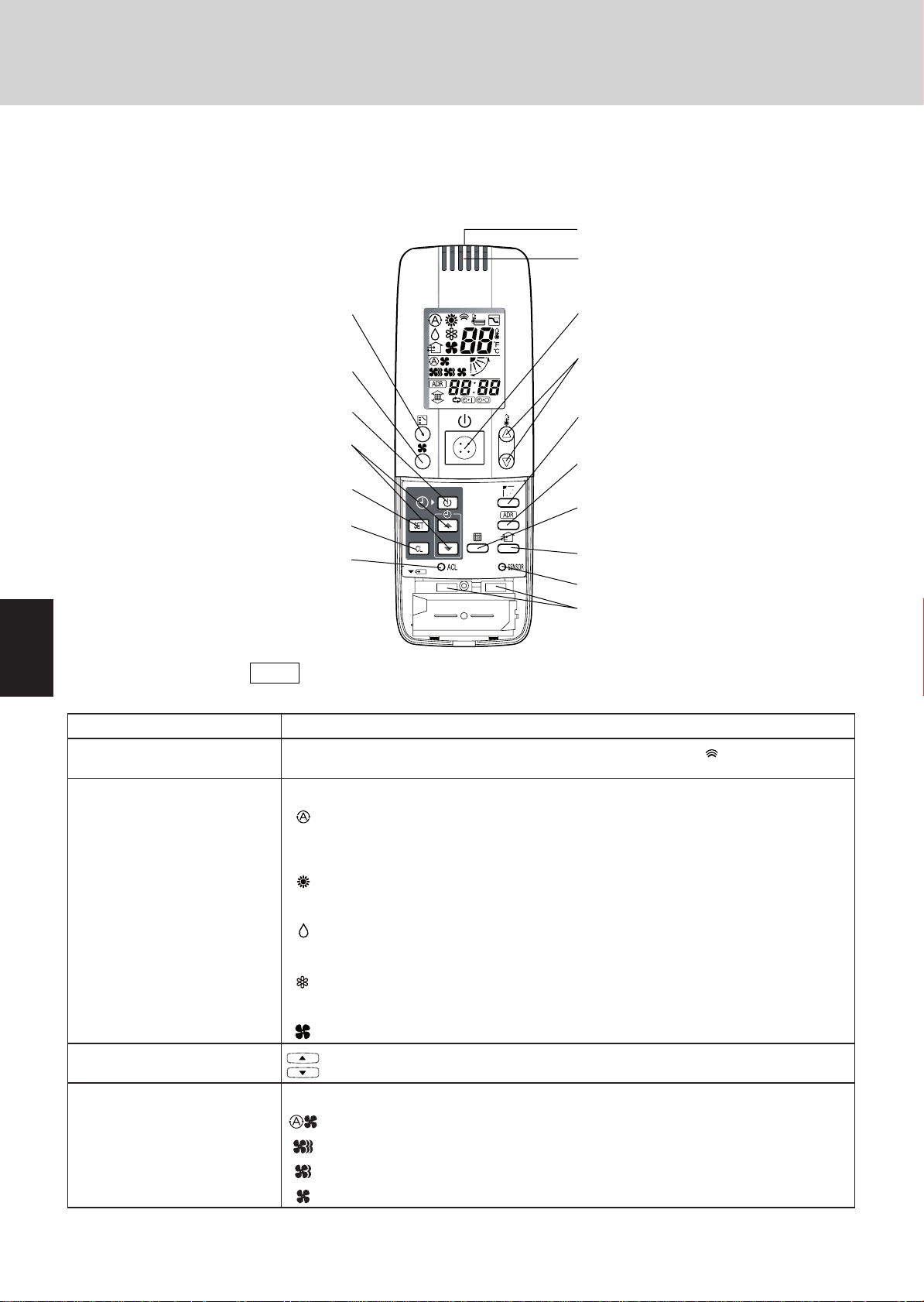
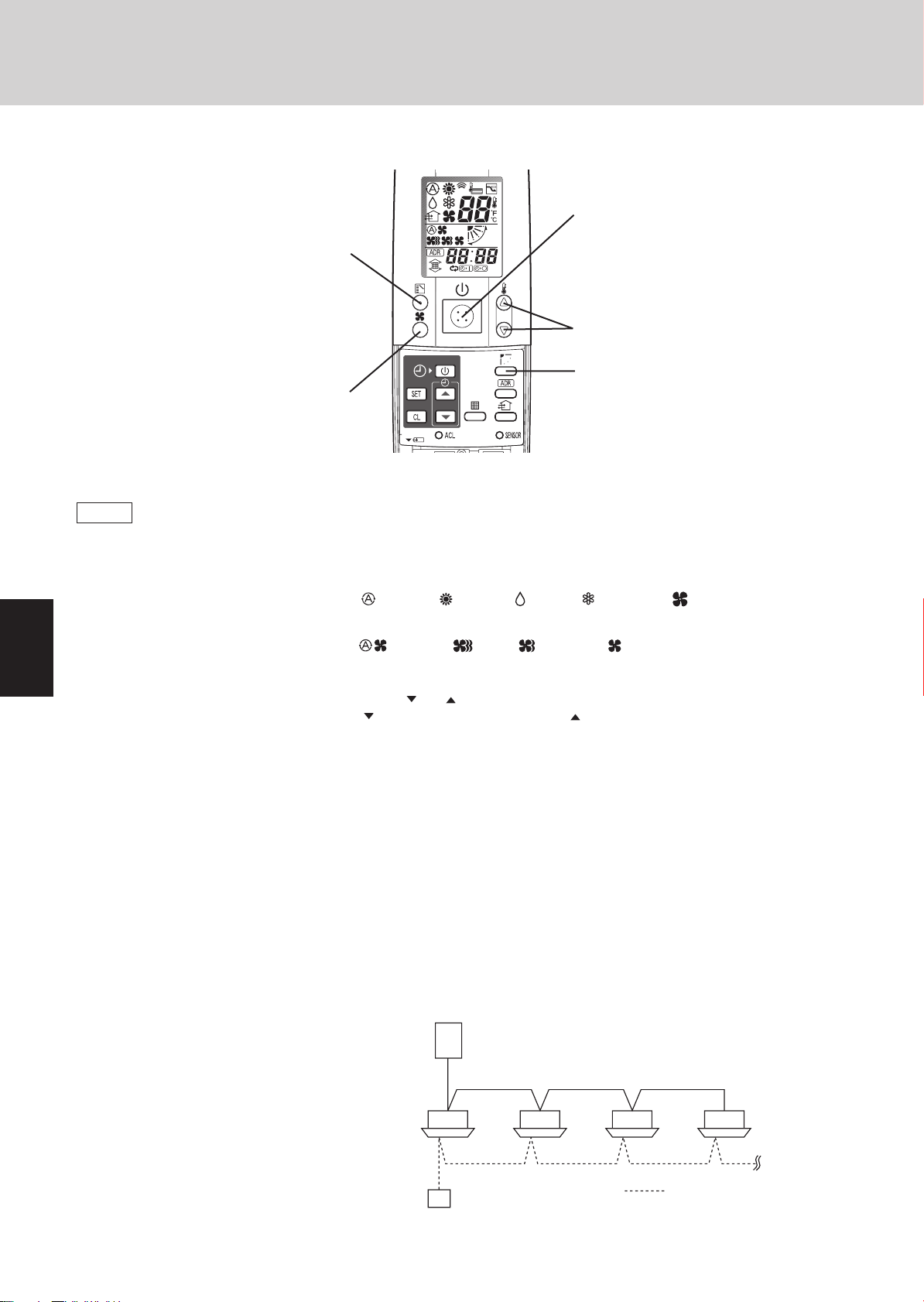
1. How to Use the Wireless Remote Controller
C: MODE button
E: FAN SPEED selector button
J: TIMER SET button
K: Time setting buttons
L: SET button
M: CL button
P: ACL button
(ALL CLEAR)
NOTE
The illustration above pictures the wireless remote control unit after the cover
has been lowered and removed.
B: Transmitter
O: Remote control sensor
A: ON/OFF operation button
D: Temperature setting buttons
I: FLAP button
G: ADDRESS button
F: FILTER button
N: VENTILATION button
H: A/C SENSOR button
Q: Slide switch
3
3
4
4
5
5
6
6
7
7
A: ON/OFF operation button This button is for turning the air conditioner on and off.
B: T ransmitter When you press the buttons on the wireless remote control unit, the
C: MODE button Use this button to select one of the following five operating modes.
(AUTO)
(HEAT)
(DRY)
(COOL)
D: Temperature setting buttons
E: FAN SPEED selector button
(AUTO)
(MED)
display to transmit the setting changes to the receiver in the air conditioner.
: Used to automatically set cooling or heating operation. Only for single heat pump
type
(Temperature range: 62
: Used for normal heating operation. Only for heat pump type
(Temperature range: 60
: Used for dehumidifying without changing the room temperature.
(Temperature range: 64 ~ 86°F (18 to 30°C))
: Used for normal cooling operation.
(Temperature range: 64
(FAN)
(HI)
(LO)
: Used to run the fan only, without heating or cooling operation.
::Press this button to increase the temperature setting.
Press this button to decrease the temperature setting.
: The air conditioner automatically decides the fan speeds.
: High fan speed
: Medium fan speed
: Low fan speed
mark appears in the
~
80°F (17 to 27°C))
~
78°F (16 to 26°C))
~
86°F (18 to 30°C))
Continued
8
8
2-4
Page 25
2. Wireless Remote Controller
Remote Control Functions
F: FILTER button If a separately installed signal receiver is being employed, this button is used to turn off its
G: ADDRESS button When a multiple number of indoor units that can be operated by the wireless remote
NOTE
H: A/C SENSOR button When you press this button (use a narrow-tipped object such as a ballpoint pen), the
NOTE
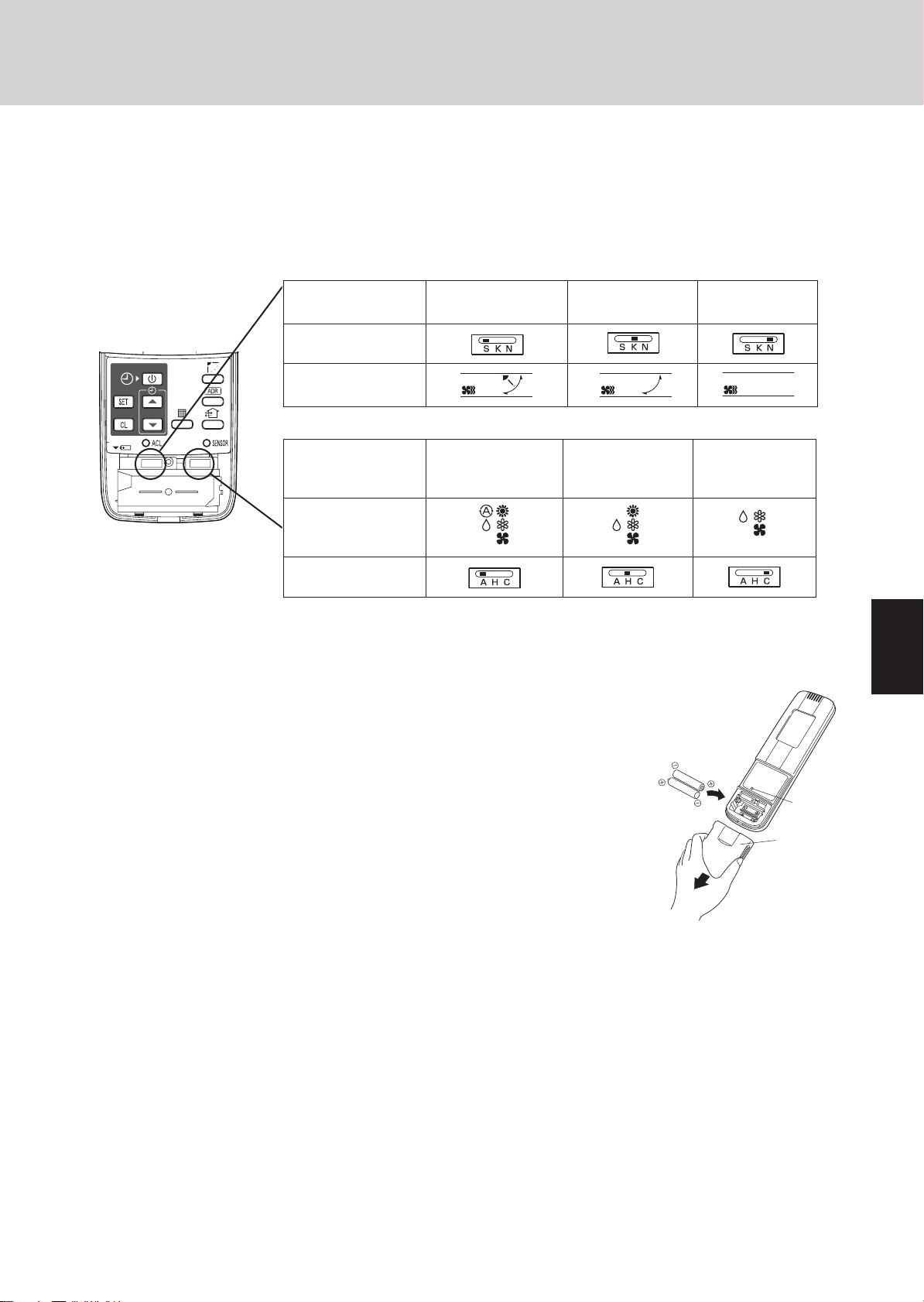
I: FLAP button 1. Use this button to set the airflow direction to a specific angle.
filter lamp. When the filter lamp has lighted, first clean the filter, and then press the FILTER
button to turn off the filter lamp. When a wired remote control unit and wireless remote
control unit are both used, the filter sign on the wired remote control unit will appear. When
this happens, first clean the filter, and then press the FILTER button on one of the remote
control units to turn off the filter sign.
control unit have been installed in the same room with a multi-unit or single-unit installation,
this button enables addresses to be set in order to prevent the sending of signals to the
wrong indoor unit. Each of up to six indoor units can be controlled separately using its own
wireless remote control unit by matching the number of the address switch on the operation
area of the indoor unit and the number used for the address of its remote control unit. (The
indoor units cannot be controlled separately when they are used in a flexible combination
format, simultaneous operation of multi units format or any other such format since they will
all operate at the same time.)
When the batteries are replaced, the address setting returns to "ALL", so you must make
the setting again.
indication will disappear on the display. The room temperature is detected by the sensor
which is built into the indoor unit and the air conditioner is controlled accordingly.
If the remote control is located near a heat source, such as a space heater or in direct
sunlight, press the A/C SENSOR button to switch to the sensor on the indoor unit.
The airflow direction is displayed on the remote control unit.
Operation mode
(COOL) or (DRY)
(HEAT) or (FAN)
(AUTO)
Cooling mode:
Heating mode:
Number of airfl ow direction settings
3
5
3
5
1
1
2
2
CAUTION
NOTE
(SWEEP) 2. Use this button to make the airflow direction sweep up and down automatically.
In the Cool mode and Dry mode, if the flaps are set in a downward
position, condensation may form and drip around the vent.
Do not move the flap with your hands.
This function is available only for models X, A, T and K.
Press this button several times until the
To stop the swing operation
Press the FLAP button again during the flap swing operation to stop the flap at the desired
position. Then, the airflow can be set from the top position by pressing the FLAP button
again.
symbol appears on the display.
3
3
4
4
5
5
6
6
2-5
7
7
8
8
Page 26
1
1
2
2
Remote Control Functions
2. Wireless Remote Controller
Indicator when swing operation is stopped
Fan and heating Cooling and dryi
During cooling and drying, the flap does not stop at the downward position.
Even if the flap is stopped at the downward position during the swing operation, it does not
stop until it moves to the third position from the top.
NOTE
J: TIMER SET button Use this button while the unit is operating to switch between timer settings.
(OFF Timer)
(OFF Cycle Timer)
(ON Timer)
K: Time setting buttons
L: SET button Use this button to set the timer.
M: CL button Use this button to clear the timer setting.
N: VENTILA TION button This is used when a ventilation fan (available commercially) is connected. Pressing the
O: Remote control sensor This detects the temperature around the remote control unit when the remote control unit
P: ACL button (ALL CLEAR) Puts the wireless remote control unit into pre-operation status. This is used after the batter-
Q: Slide switch This switch is for setting the operation mode of the indoor unit and setting the flaps.
This function is available only for models X, A, T and K.
: The air conditioner stops after a preset time elapses.
: The air conditioner always stops after a preset time elapses.
: The air conditioner starts after a preset time elapses.
: Press this button to increase the time.
: Press this button to decrease the time.
VENTILATION button turns the fan on and off. The ventilation fan also turns on and off when
the air conditioner unit is turned on and off. (The display of the remote control unit shows
" while the ventilation fan is running.)
"
* If the VENTILATION button is held down for 4 or more seconds when the batteries have
been replaced, "
position has been selected using the sensor button.
ies have been replaced or when the slide switch setting has been changed.
" appears on the display, and the ventilation fan can be used.
ng
3
3
4
4
5
5
6
6
7
7
NOTE
The wireless remote control unit sends the temperature signal to the air
conditioner regularly at fi ve-minute intervals. If the signal from the wireless
remote control unit stops for more than ten minutes due to the loss of the
wireless remote control unit or other trouble, the air conditioner will switch to
the temperature sensor which is built into the indoor unit and control the room
temperature. In these cases, the temperature around the wireless remote
control unit may differ from the temperature detected at the air conditioner's
position.
When low fan speed is selected and the air conditioner is in cooling opera-
tion at a low outdoor temperature of less than 50°F (10°C), the air conditioner
may automatically switch to medium fan speed to prevent freezing.
8
8
2-6
Page 27
Remote Control Functions
2. Wireless Remote Controller
2. Receiver
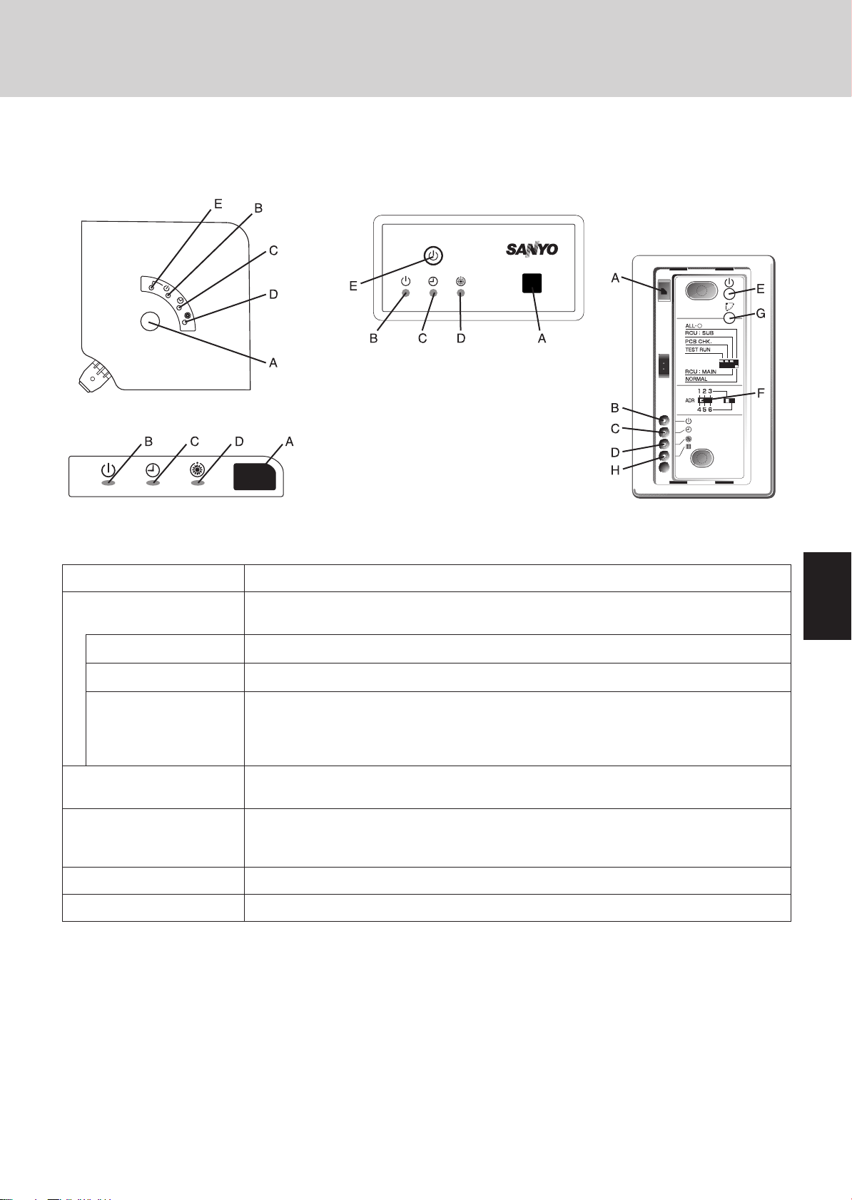
The signal receivers with the exception of the separately installed signal receiver are mounted on the indoor units.
X type
K type
A: Receiver This section picks up infrared signals from the wireless remote control unit (transmitter).
Indication lamps One of these lamps will blink when trouble has occurred. When an indicator lamp starts to
blink, refer to “Troubleshooting” on page 2-14.
T type
Separately installed
signal receiver
(A, U, D type)
1
1
2
2
B: Operation lamp This lamp lights when the appliance is turned on.
C: Timer lamp This lamp lights when the system is being controlled by the timer.
D: Standby lamp • This lamp lights at the following times during heating operations:
When operation has started, when the thermostat has been activated, during a defrosting
operation.
• The lamp blinks when trouble has occurred.
E: Emergency operation
button
F: ADDRESS switch This switch is used in order to prevent the sending of signals to the wrong indoor unit when
G: SWING button When this button is pressed, the airflow sweeps up and down automatically.
H: FILTER lamp This lamp lights to indicate that it is time to clean the filter.
• If two beeps are heard, the operation lamp among the indication lamps has lighted and the timer lamp and standby
lamp blink alternately. In cases where heat pump models are used, this indicates a cooling/heating mode mismatch
and, as such, operation in the desired mode cannot be performed. (The same beeps will be heard and the same
operation lamps will light when auto cooling/heating has been selected on a model which does not have the auto
cooling/heating function.)
• When local operation has been set to disable because the centralized control mode is established, for instance,
pressing the ON/OFF operation button, MODE button or temperature setting buttons results in the sounding of
five beeps, and the attempted change in the operation will not be accepted.
This is used when operation cannot be performed due to trouble with or loss of the wireless
remote control unit.
a multiple number of indoor units that can be operated by the wireless remote control units
have been installed in the same room.
3
3
4
4
5
5
6
6
7
7
2-7
8
8
Page 28
2. Wireless Remote Controller
3. Operation
STEP 2
STEP 3
Remote Control Functions
STEP 1, 6
STEP 4
STEP 5
1
1
2
2
3
3
4
4
5
5
NOTE
STEP 1 To start the air conditioner: Press the operation button (ON/OFF button).
STEP 2 Setting the mode: Press the MODE button to select the mode of your choice.
STEP 3 Setting the fan speed: Press the FAN SPEED selector button to select the fan speed of your choice.
STEP 4
STEP 5 Setting the airflow direction: When more than one indoor unit is connected, the UNIT button is used first to
STEP 6 To stop the air conditioner: Press the operation button (ON/OFF button) again.
Automatic heating and
cooling
Simultaneous operation of
multiple units (Group
control)
• To warm up the system, the power mains must be turned on at least five (5) hours before operation.
[ (AUTO), (HEAT), (DRY), (COOL) or (FAN) ]
[ (AUTO), (HI.), (MED.) or (LO.) ]
If AUTO is selected, the fan speed switches automatically.
Setting the temperature:
The air conditioner automatically performs heating and cooling operation based on the
difference between the temperature setting and room temperature. All indoor units in the
same refrigerant system can be operated with a single group control.
Group control is suitable for air conditioning of a large room using multiple air conditioning
units.
• One remote control unit can control up to eight indoor units.
• All indoor units have the same settings except for the airflow direction.
• The temperature sensors at the indoor unit side are used.
Use the or button as appropriate to change the temperature setting as desired.
( reduces the temperature, and increases the temperature. )
* The temperature cannot be set during FAN mode operation.
select a unit. Then use the FLAP button to set the airflow direction to a specific
angle or to sweep.
6
6
7
7
8
8
Outdoor unit
Remote control unit
2-8
Indoor unit
Signal line
Page 29
2. Wireless Remote Controller
4. Using the Wireless Remote Control Unit
Slide switch This is used to set the operation mode of the indoor units and to set the flaps.
• Depending on the indoor unit used, the operation display and airflow direction display
settings will differ as shown below.
• Use a pointed implement to change the switch position.
• When the switch position has been changed, press the ACL button.
* For details on the flap functions, refer to the operating instructions of the indoor unit used.
Remote Control Functions
With the battery cover
removed
How to install
batteries
How to use the
wireless remote
control unit
Model which supports
different flap settings
Slide switch position
Flap display on wireless
remote control unit
Heat pump (with auto
cooling/heating
function)
Operation mode display
on wireless remote
control unit
Slide switch position
• Before use, check that the slide switch has been set to the position shown in the figure
above. For details on how to set the slide switch, consult your dealer.
1. Slide the cover in the direction indicated by the arrow and
remove it.
2. Install two AAA alkaline batteries. Make sure the batteries
point in the direction marked in the battery compartment.
3. Use a pointed implement to press the ACL button.
• The batteries last about a year, depending on how much
you use the wireless remote control unit. Replace the
batteries when the wireless remote control unit's display
fails to light, or when the remote control cannot be used
to change the air conditioner's settings.
• When the batteries are to be replaced, make sure that both
batteries are new and that the same kind of battery is used.
• Remove the batteries if the wireless remote control unit is
not going to be used for a prolonged period.
• Dispose of the used batteries at the designated location.
• Point the wireless remote control unit's transmitter at the signal receiver. If the signal is
received properly, a beep is heard. (Two beeps are heard only when operation starts up.)
• Signals can be received over a distance of approximately 26 ft. This distance is
approximate: it may be slightly more or less depending on how much charge remains in the
batteries and on other factors.
• Ensure that the signals will not be blocked by any objects positioned between the transmitter
and signal receiver.
• Avoid placing the wireless remote control unit where it will be exposed to direct sunlight or in
the direct path of the air blown out from the air conditioner, near a heating appliance, etc.
• Do not drop, throw or wash the wireless remote control unit.
• Signal reception may not be accepted in rooms with fluorescent lights that use the electronic
instantaneous lighting system (rapid start system) or inverter system.
For further details, contact your dealer.
Swing-only model No-flap model
Heat pump (without
auto cooling/heating
function)
Cooling only
ACL
button
Cover
1
1
2
2
3
3
4
4
5
5
6
6
7
7
2-9
8
8
Page 30
2. Wireless Remote Controller
Remote Control Functions
1
1
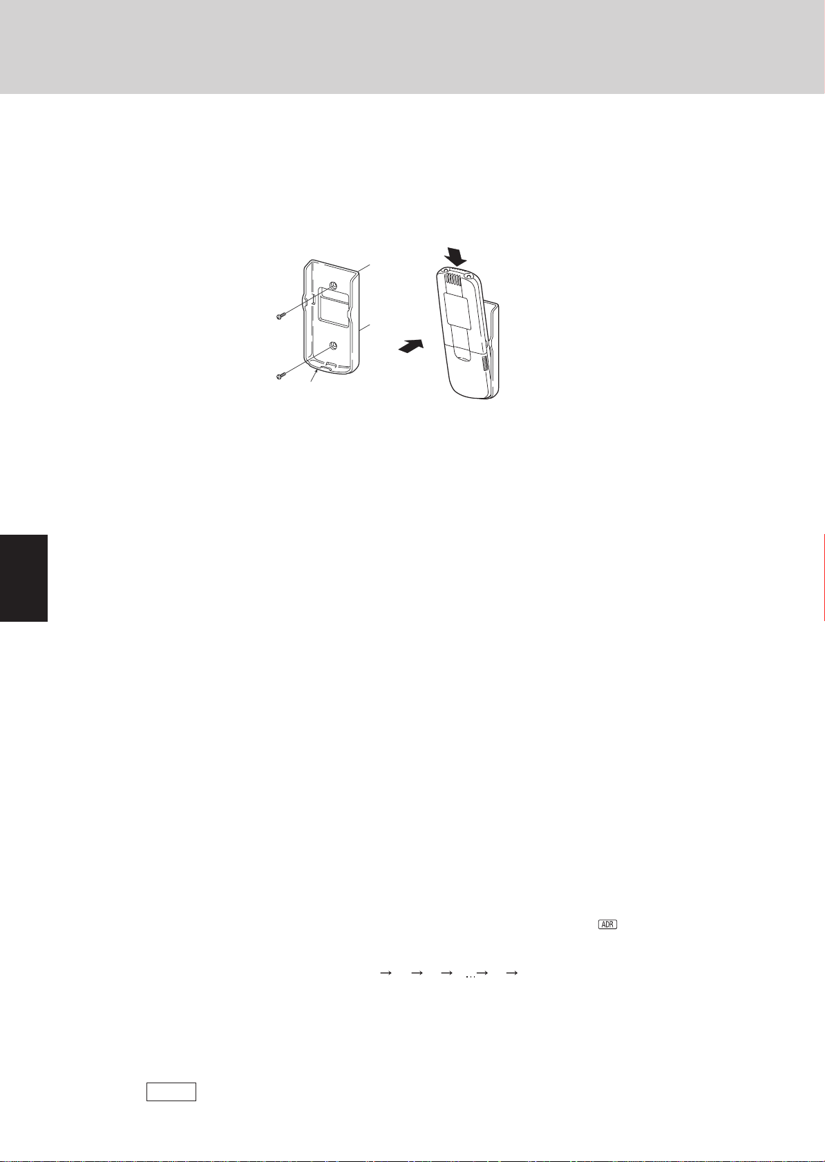
When mounting the
wireless remote control
unit on a wall for use
Secure the installation fitting of the wireless
remote control unit using the screws.
Installation fitting of wireless remote control unit
Operating tips • D o not operate the wireless remote contr ol unit too far away fr om the signal receiver .
• Before mounting the wireless remote control unit on the wall, place the unit at the mounting
position, press the ON/OFF operation button and check that the signals are received
properly.
• To remove the wireless remote control unit, disengage it by pulling it toward you.
Doing so may cause operational errors.
Make absolutely sure that the wireless remote control unit and signal receiver are both in
the same room.
• When operating the wireless remote contr ol unit, point it directl y at the signal receiver.
A beep is heard when a signal is received properly.
• Avoid places where the wireless remote contr ol unit will be obscured by curtains, etc.
Remove it before operation.
2
1
Press.
Place here.
Procedure for installing the
wireless remote control unit
2
2
3
3
4
4
5
5
6
6
7
7
5. Address Settings
How to check the
addresses
How to set the
matching address
When a multiple number of indoor units that can be operated by the wireless remote control unit
have been installed in the same room with a multi-unit or single-unit installation, this button enables
addresses to be set in order to prevent the sending of signals to the wrong indoor unit. Each of up to
six indoor units can be controlled separately using its own wireless remote control unit by matching
the number of the address switch on the operation area of the indoor unit and the number used for
the address of its wireless remote control unit. (The indoor units cannot be controlled separately
when they are used in a flexible combination format, simultaneous operation of multi units format or
any other such format since they will all operate at the same time.)
The signal receiver has an address switch for signal reception, and the wireless remote control unit
has an address switch for signal transmission.
When the ADDRESS button on the wireless remote control unit is pressed, the current address
appears on the wireless remote control unit's display. The buzzer sounds if the address
displayed matches the signal receiver's address. (The buzzer always sounds if “ALL” appears
as the address display.)
If “ALL” appears as the address display, operations can be performed irrespective of the signal
receiver's address. Point the wireless remote control unit at the signal receiver of the unit to be
operated, and send the signal.
Wireless remote control units address setting
1. When the ADDRESS button is held down for 4 or more seconds, “ ” lights on the
wireless remote control unit's display, and the current address blinks.
2. Each time the ADDRESS button is now pressed, the address changes by one setting in the
following sequence: ALL 1 2 3 6 ALL.
Select the setting which matches the setting of the address switch in the operation area of
the indoor unit to be operated.
3. When the SET button is now pressed, the address stops blinking and lights instead, and it
remains on the display for 5 seconds.
The buzzer sounds if the setting matches the setting of the address switch in the operation
area of the indoor unit.
8
8
NOTE
When the batteries are replaced, the address setting returns to “ALL ”.
2-10
Page 31

2. Wireless Remote Controller
Wireless remote
control unit
address displays
Remote Control Functions
……
X type
Position of
address switch on
signal receiver
(inside indoor unit)
T type
Position of
address switch on
signal receiver
(inside indoor unit)
K type
Position of
address switch
inside indoor unit
A, U, D type
Position of
address switch in
signal receiver
* The address switch
in the operation
area may be set to
any position.
* The address switch
in the operation
area may be set to
any position.
* The address switch
in the operation
area may be set to
any position.
* The address switch
in the operation
area may be set to
any position.
For positions 1, 2 and 3, set the
knob to the left; conversely, for 4, 5
and 6, set the knob to the right.
……
For positions 1, 2 and 3, set the
knob to the left; conversely, for 4, 5
and 6, set the knob to the right.
……
……
For positions 1, 2 and 3,set the
knob upward (1); conversely, for 4,
5 and 6, set the knob downward
(ON).
For positions 1, 2 and 3, set the
knob to the left; conversely, for 4, 5
and 6, set the knob to the right.
……
1
1
2
2
3
3
2-11
4
4
5
5
6
6
7
7
8
8
Page 32

2. Wireless Remote Controller
6. Emergency Operation
In any of the following events, use the Emergency operation button to operate the air
conditioner on a makeshift basis.
• When there is no charge remaining in the wireless remote control unit's batteries
• When the wireless remote control unit has failed
• When the wireless remote control unit has been lost or misplaced
X type Initiate operation using the Emergency operation button in the operation area of the indoor unit.
Operation
Press the Emergency operation button.
The air conditioner initiates a cooling operation when its operation is started up at
a room temperature of 75°F (24°C) or above.
Conversely, it initiates a heating operation when its operation is started up at a
room temperature below 75°F (24°C).
Shutdown
Remote Control Functions
1
1
2
2
3
3
4
4
5
5
Press the Emergency operation button once more.
T type Initiate operation using the Emergency operation button in the signal receiver on the indoor
unit.
Operation
Press the Emergency operation button.
The air conditioner initiates a cooling operation when its operation is started up at
a room temperature of 75°F (24°C) or above.
Conversely, it initiates a heating operation when its operation is started up at a
room temperature below 75°F (24°C).
Shutdown
Press the Emergency operation button once more.
K type Initiate operation using the Emergency operation button in the operation area of the indoor unit.
Operation
Set the ON/OFF operation switch to “OFF” first.
Then set it to “ON. ”
If a heat pump is used, the air conditioner initiates a cooling operation when its
operation is started up at a room temperature of 75°F (24°C) or above or it initiates
a heating operation when its operation is started up at a room temperature below
75°F (24°C).
6
6
7
7
8
8
NOTE
Shutdown
Set the ON/OFF operation switch to “OFF.”
• TEST is used to initiate a trial run when the air conditioner is first installed. It is not used
under normal circumstances.
• To restart the wireless remote control unit's operation, the ON/OFF operation switch must
be set to ON without fail. If it is kept at the OFF setting, the signals from the wireless remote
control unit will not be accepted.
2-12
Page 33

2. Wireless Remote Controller
A, U, D type Initiate operation using the Emergency operation button in the signal receiver.
1. Press the Emergency operation button.
The air conditioner initiates a cooling operation when its operation is started
up at a room temperature of 75°F (24°C) or above.
Conversely, it initiates a heating operation when its operation is started up at a
room temperature below 75°F (24°C).
2. When the SWING button is pressed, the air direction is automatically switched
from upward to downward or vice versa.
Shutdown
Press the Emergency operation button once more.
Remote Control Functions
1
1
2
2
3
3
4
4
5
5
2-13
6
6
7
7
8
8
Page 34

2. Wireless Remote Controller
7. T roubleshooting
Check out the following points before requesting service.
Trouble Possible Cause Remedy
Remote Control Functions
1
1
2
2
The air conditioner
does not run even
when the ON/OFF
operation switch has
been set to ON.
Check again.
Auto cooling/heating or heating appears on the display even though the air
conditioner is a cooling-only model.
Trouble Possible Cause
(An indicator lamp is blinking.)
Operation
Operation
Timer
Timer
Is the air conditioner in the shutdown mode or
was the switch operated after a power failure?
How about the local power switch? If it was off, set it now to on.
Have any of the fuses blown? If a fuse has blown, contact your dealer.
Is the ON timer operation mode established? Clear the timer operation.
If the signal receiver's NORMAL/ALL OFF
switch set to “ALL OFF”?
Have the wireless remote control unit's
batteries run down?
Do the indication lamps show a cooling/heating
mismatch or is the auto cooling/heating
function not available?
Preparing for
operation
Preparing for
operation
• Some kind of trouble has occurred in communication between the signal
receiver and indoor unit. Alternatively, the wrong address has been set
when a wired remote control unit is used.
• Some kind of trouble has occurred in communication between the indoor
unit and outdoor unit.
Press the wireless remote control unit's
ON/OFF operation button again.
If it is, set it to the “NORMAL” position and
cancel the operation.
If they have, replace them with new ones.
Change the operation mode.
Change the setting of the wireless remote
control unit's slide switch. (See page 2-9)
3
3
4
4
5
5
6
6
7
7
Operation
Operation
Operation
Contact your dealer.
Operation
Operation
If the trouble persists even after performing the checks recommended above, shut down the air conditioner's operation, set the
local power switch to OFF, and contact your dealer with the model number and trouble symptoms. You must NOT attempt to
make repairs yourself due to the dangers involved. If one or more of the indication lamps is blinking, give this information to the
dealer as well.
Timer
Timer
Timer
Timer
Timer
Preparing for
operation
Preparing for
operation
Preparing for
operation
Preparing for
operation
Preparing for
operation
• The indoor unit's protection device has been activated. Alternatively, the
auto flap connector of the ceiling panel has been disconnected.
• The outdoor unit's protection device has been activated.
• Something is wrong with the temperature sensor.
• The outdoor unit's compressor has been protected.
• A trial run mode is underway. Set the trial run mode to Off.
8
8
2-14
Page 35

3. Timer Remote Controller (RCS-TM80BG)
1. How to Use the Timer Remote Controller
Operating buttons
13
Remote Control Functions
1
12
11
10
9
8
Display
2
3
4
5
6
7
121 2 5 73 86 9 31104 11 13
1
1
2
2
3
3
4
4
2830 182122
29 26
2-15
5
5
15 141617232527
2024
6
6
7
7
8
8
Page 36

1
1
2
2
3. Timer Remote Controller (RCS-TM80BG)
2. Names and Operations
Operation Section (Refer to the previous page)
1. Start/Stop button
Pushing this button starts, and pushing again stops the
unit.
2. Operation lamp
The lamp is turned on when an air conditioner is in operation.
This lamp blinks when an error occurs or a protective
device is activated.
3.
4. Temperature setting buttons
5.
6.
7.
8. Timer setting buttons
9.
Mode Select button
Pushing this button to select an operation mode. (AUTO
/HEAT /DRY /COOL /FAN ).
Changing the temperature setting.
FAN speed button
Changing the fan speed.
Swing/Air direction button *1
Use this button to set the auto swing or air direction to a
specifi c angle.
Unit Select button
When more than one indoor unit is operated by one remote control unit, this button is used to select a unit when
adjusting the air direction.
Weekly Program Function)
(
FILTER reset button
Use this button to reset the fi lter sign.
When
fi lter.
is displayed, press this button after cleaning the
10.
11.
12.
13. Remote control sensor
*1 Do not move the fl ap (vertical airfl ow adjustment board)
Remote Control Functions
Ventilation button
Use this button when you installed a fan available in the
market. Pressing this button turns on and off the fan.
When turning off the air conditioner, the fan will be also
turned off.
(While the fan is operating, will appear in the display.)
*If is displayed on the LCD of the remote control unit
when pressing the ventilation button, no f ans are installed.
Inspection button
Do not use this button.
Sleeping button
Sleeping Function)
(
Normally, the temperature sensor of the indoor unit is
used to detect the temperature. However, it is also possible to detect the temperature around the remote control
unit.
with your hand.
The fl ap is automatically directed down when the unit is
stopped.
The fl ap is directed up during the HEAT standby. The
fl ap starts swinging after the HEAT standby is cancelled, although the AUTO fl ap indication on the remote
control unit is displayed during the HEAT standby.
3
3
4
4
5
5
6
6
7
7
8
8
2-16
Page 37

3. Timer Remote Controller (RCS-TM80BG)
Display Section (Refer to the page 2-15)
Remote Control Functions
1.
2.
3.
4. Timer program
5.
6.
7. Present time
8.
9.
10.
11. Upper and lower limit indication of the outing func-
12. Operation Mode indication
13. Temperature indication
14. °F / °C temperature unit indication
15.
16.
SETTING indication
Appears when the timer program is being set.
UNIT indication
Indicates the unit No. of the indoor unit which is selected
with the Unit Select button, or the unit in which an abnormality occurs.
TIMER No. indication
Appears when the time program is being set.
: The indoor unit starts operation at the programmed
time.
: The indoor unit stops operation at the programmed
time.
Today’s day of the week
Indicates today’s day of the week.
Program schedule indication
Appears under days that are scheduled for program operation.
Displays the present time on a 24-hour clock. Also, displays settings in the various setting modes.
TIMER OFF indication
Displayed when the timer has been turned OFF.
ERROR indication
Displayed when a mistake is made during timer setting.
Outing indication ( Outing function)
Appears when the outing function is set.
tion
: Indicates the upper limit of the temperature
: Indicates the lower limit of the temperature
Displays the selected operation mode. (AUTO
/DRY /COOL /FAN ).
Indicates the set temperature.
Remote control sensor indication
Appears when the remote control sensor is used.
Centralized control indication
Appears when operated in centralized control. If the
remote control operation is not permitted to the remote
unit, when the Start/Stop button, Mode Select button or
Temperature setting button is pressed, fl ashes and
rejects the change.
/HEAT
17. Operation mode change control indication
Displays when an operation mode is entered by the remote control unit, while another operation mode has been
already selected. This indicates that the operation mode
cannot be changed.
Disabled Feature indication
18.
Displayed if the selected feature was disabled during
installation.
Heating standby mode indication
20.
appears when the fan of the indoor unit is stopped or in
low fan speed.
21.
22.
23.
24.
25.
26.
27.
28.
29.
30. Unit No. indication
31.
/ / / Fan mode select indication
The selected fan mode is displayed.
SWING indication
Appears while the fl ap swings.
Flap position indication
Indicates the fl ap position.
Filter indication
Appears when fi lter needs cleaning. Clean the fi lter.
Inspection indication
Appears when the protective device is activated or when
an abnormality occurs.
Ventilation indication
Appears when a fan available in the market is installed
and is operating.
Oil indication
Appears when the engine oil needs to be changed. (Appears when the gas heat pump air conditioner is used.)
Sleeping
Appears during the sleeping function.
CAUTION
Appears when the protective device is activated or when
an abnormality occurs.
Indicates the unit No. of the selected indoor unit.
TEST indication
Appears while in test operation.
1
1
2
2
3
3
4
4
5
5
2-17
6
6
7
7
8
8
Page 38

3. Timer Remote Controller (RCS-TM80BG)
3. Installation Manual for Timer Remote Controller
Accessories for remote controller switch
Remote controller Wood screws Wire joints Operation manual Installation manual
(with 8 in.
wire)
4. How to install the Remote Controller
CAUTION
Do not supply power to the unit or try to operate it until the tubing and wiring to the outdoor unit is
completed.
Do not twist the control wiring with the power wiring or run it in the same metal conduit, because
this may cause malfunction.
Install the remote controller away from sources of electrical noise.
Install wiring correctly(incorrect wiring will damage the equipment).
Install a noise fi lter or take other appropriate action if electrical noise affects the power supply circuit
of the unit.
When wiring, do not connect the remote controller wires to the adjacent terminal block for the power
wiring. Otherwise, the unit will break down.
Use shielded wires for remote control wiring and ground the shield on indoor unit sides. (Fig. 2-1)
Otherwise misoperation due to noise may occur.
Remote Control Functions
1
1
2
2
3
3
4
4
5
5
The mounting position for the remote controller should be located in an accessible place for control.
Never cover the remote controller or recess it into the wall.
(1) When you open the decorative cover (Fig. 2-4), you will see 2 gaps under the remote controller.
Insert a coin into these gaps and pry off the back case.
(2) Attach the back case with the 2 wood screws provided. Using a screwdriver, push open the cut-outs on the back case.
These holes are for screws. (Fig. 2-5)
(3) Connect the remote controller wiring (2 wires) correctly to the corresponding terminals in the electrical component box of
the indoor unit.
(4) To fi nish, fi t the back tabs of the case into the remote controller and mount it.
Basic Wiring Diagram
Connection diagram
Terminal board for
indoor unit remote
controller wiring
Remote controller wiring
(field supply)
Ground
1
2
Shielded wire
Fig. 2-1
Approx.
8 in.
Connector
W
1
2
BK
Power wire from remote
controller unit
Remote
controller
unit
6
6
7
7
8
8
2-18
Page 39

3. Timer Remote Controller (RCS-TM80BG)
Remote Control Functions
Use AWG#20 to AWG#16 wires.
Remote controller wiring can be extended to a maximum
of 1640 ft.
(1) Strip the insulation to approximately 35/64" from the ends
of the wires that will be connected.
(2) Twist together the 2 wires and create a crimp connection
at the wire joint.
(3) If a special crimping tool is not used, or if the connection
is soldered, insulate the wires using insulation tape.
Remote controller
5. Group Control Using 2 Remote Controllers
It does not matter which of the 2 remote controllers you
set as the main controller. When using multiple remote
controllers (up to 2 can be used), one serves as the
main remote controller and the other as the sub-remote
controller.
2P terminal
base for remote
control wiring
(main)
1
1
Indoor unit
No. 1
: Ground (earth)
6. Remote Controller Setting Mode
To set the remote controller main/sub setting or change the sensor, follow the steps below.
Press both
4 seconds together.
Select CODE No. with
Change DATA with
Press
* DATA is memorized in the RCU. (DATA setting will not be changed even
when the power is turned off.)
* Make sure to set [Normal] for RCU. CK.
and buttons on the remote controller for more than
buttons.
(TIMER) buttons.
. Finally, press .
CODE
ITEM
Provided wire joint (white)
Remote controller wiring
Power wire from remote
controller unit
Connection wiring
2
for group control
1
2
Room temperature sensor
2
Indoor unit
No. 2
Fig. 2-3
ITEM
RCU. Main/Sub
Clock display
RCU. CK
Fig. 2-2
(sub)
1
2
1
2
Indoor unit
No. 3
24 hours
Main unit RCU
DATA
MainSub
12 hours
NormalRCU. CK
Wire joint
1
2
Indoor unit
No. 8
(AM/PM)
1
1
2
2
7. Indoor Unit Setting Mode
To select the ventilation setting or change the temperature unit, follow the steps below.
Press
onds together.
Select CODE No. with
Change DATA with
Press
* DATA is memorized in the indoor unit. (DATA setting will not be changed
even when the power is turned off.)
+ + buttons on the remote controller for more than 4 sec-
buttons.
(TIMER) buttons.
. Finally, press .
8. To Display the Sensor Temperature:
Press both and buttons on the remote controller for more than 4 seconds together.
Change the sensor address (CODE No.) with
Select the UNIT No. which you want to call with the
Press the
button to fi nish service mode.
buttons.
button.
9. To Display the Trouble History:
Press both and buttons on the remote controller for more than 4 seconds together.
Change the alarm message:
Press the
button to fi nish service mode.
buttons
CODE No.
CODE
ITEM
(New) (Old)
ITEM
Vent. button YesNo
Temperature unit
3
3
DATA
o
C
o
F
4
4
5
5
6
6
7
7
2-19
8
8
Page 40

3. Timer Remote Controller (RCS-TM80BG)
g
Fig. 2-4
. 2-5
Fi
Caution when installing the remote controller
*1 Install the remote controller more than 3-3/8" apart from the wall surface.
*2 To install the remote controllers side-by-side, keep the space between each for more than 4-59/64".
*3 To install the remote controllers one above the other, keep the space between each for more than 1".
Remote Control Functions
1
1
2
2
3
3
4
4
5/32
4-23/32
1-1/2
11
1/16
7/64
4-23/32
5/8
11/64 × 3/8
3/16 × 27/64
5
5
6
6
7
7
8
8
3/16 × 3/8
1-13/16
53/64
4-13/32
15/16
3-9/32
4-35/64
11/64 × 3/8
unit :in.
2-20
Page 41

3. Timer Remote Controller (RCS-TM80BG)
10. Setting the Present Time
1. Press and hold for more than 2 seconds to enter in the present
day and time setting mode.
Once you enter in the setting mode,
2. Set “
3. Press
4. Press
” to today’s day of the week.
Press
Su
Fr ....
*1
While in time setting mode, the temperature setting buttons function as
Set the present hour and press
The “hour” digits light up, and the “minute” digits start fl ashing.
*2
If the clock uses the 12 hours AM/PM setting, the hour is displayed in the range of AM 0 to
11/PM 0 to 11.
Set the present minute and press
*1 to move “ ” (fl ashing on the display) in the order of :
Mo Tu .... Press to move it in the order of : Su St
(changing day) button.
to change the present “hour” in the range of 0 to 23*2.
.
, to change the present “minute” in the range of 0 to 59.
, “ ”(day) and “time” fl ash.
. The day and time are set and fi nishes the setting mode.
Remote Control Functions
1,3,43,4 2
Note
• The unit returns to the normal mode if
during the setting. In this case, all the settings in progress will be lost.
• If the present time is invalid, “– – : – –” is displayed.
If the power failure for more than 1 hour occurs, check if the set data of day and time are valid.
is pressed or there is no operation made for 3 minutes
1
1
2
2
3
3
4
4
2-21
5
5
6
6
7
7
8
8
Page 42

3. Timer Remote Controller (RCS-TM80BG)
11. Weekly Program Function
Checking Weekl y Timer
Set the weekly program assigning a given timer to each day of the week.
Maximum of 6 programs a day and 42 programs a week can be set.
Select the day and the TIMER number you want to program.
Program image diagram
Vertical scale indicates the TIMER No.,
and horizontal scale indicates the day.
* If the day is changed, the TIMER No.
returns to “1”.
TIMER No.
Su Mo Tu We Th Fr Sa
1
2
3
4
5
6
Remote Control Functions
button
Select a section from
the 42 programs.
1
1
2
2
3
3
4
4
1. Press
” and start setting.
“
Once you enter the program confi rmation mode, the
present day is indicated as TIMER No. “1”.
2. Select the day.
Press
tally on the day to select.
Press to move “ ” (fl ashing on the display) in the
order of : Su Mo T u....
Press to move it in the order of : Su Sa Fr....
“– – : – –” is displayed when the program is not set.
3. Select a Timer number.
Press
Press to move up from 1.
Press to move down from 6.
to enter the program confi rmation mode
and / to move the “ ” horizon-
/ to select a TIMER No. from 1 to 6.
31
program CHeck
TIMER No. 1~6
2
5
5
6
6
7
7
8
8
2-22
Page 43

3. Timer Remote Controller (RCS-TM80BG)
Changing the Program Timer
To set the weekly program, follow the steps below.
1. Select the program you want to set in the program
confi rmation mode, and press
setting mode of the program currently displayed.
* In the program setting mode,
“minute” and “item” fl ash on the display.
2. Set the “hour”. (program step 1)
Press
Confi rm the “hour” and press
gram changing mode
3. Set the “minute”. (program step 2)
Press
Confi rm the “minute” and press
(the program pattern selection mode).
/ to set the “hour”.
(setting of the “minute”).
/ to set the “minute”.
. The enters the
, “hour”,
. The enters the pro-
.The unit enters
2,3,4
Remote Control Functions
1,2,3,4 4
Program step1
Program step2
normal remote controller
PROGRAM CANCEL
program check
Program
SET,CANCEL,DEL
SET
CANCEL,DEL
CANCEL,DEL
PROGRAM
CANCEL
SET,CANCEL
Changing hour digits
SET
Changing minute digits
SET
Changing patterns
Selecting copy source
SET
Selecting copy destination
1
1
2
2
3
3
4
4
5
5
2-23
6
6
7
7
8
8
Page 44

3. Timer Remote Controller (RCS-TM80BG)
4. Set the program pattern.
(program step 3)
There are 4 program patterns.
Pressing
Pattern 1
The indoor unit starts operation at the programmed
time.
Pattern 2
The indoor unit stops operation at the programmed
time.
Pattern 3
The indoor unit starts operation at the programmed
time and changes the temperature settings.
/ repeats the following display patterns.
Remote Control Functions
Pattern 1
Pattern 2
Pattern 3
1
1
2
2
3
3
4
4
Press
Pattern 4
The indoor unit changes the temperature setting at
the programmed time.
Press
Select the program pattern and press
Note
If you press
If there is no operation made for 3 minutes during the setting, it returns to the normal mode.
In this case, all the settings in progress will be invalid.
/ to change the temperature setting.
Pattern 4
/ to change the temperature setting.
. The program timer setting is confi rmed and the unit enters the confi rmation mode .
during the setting, it returns to the program confi rmation mode.
5
5
6
6
7
7
8
8
2-24
Page 45

3. Timer Remote Controller (RCS-TM80BG)
Deleting the Program Timer
To delete the program timer setting, follow the steps below.
1. Press
2. Press
lete.
3. Press
4. Press
to enter the program confi rmation mode.
/ to select the day of the program you want to de-
/ to select a TIMER No. (from 1 to 6).
to display the program setting mode .
Remote Control Functions
5. Press
Note
After deleting, the unit returns to the program confi rmation mode
If you press
confi rmation mode.
If there is no operation made for 3 minutes during the setting, the unit re-
turns to the normal mode.
Invalidating Program Timer
to delete the program.
.
during the setting, the unit returns to the program
43512
If you want to adjourn the program operation for more than 1 week, you can
invalidate all the timer settings.
Once the timer settings are invalidated, the program will not be operated until the invalidation is cancelled.
<<How to invalidate the program timer>>
Press and hold for more than 2 seconds.
is displayed and the programs will be invalidated from the next one.
<<How to cancel the program timer invalidation>>
Press and hold for more than 2 seconds.
disappears and the programs will be validated from the next one.
If Power Failure Occurred
If the power recovers in a short time period, the program after the recovered time will be valid.
If the power recovered more than 1 hour after the failure, the present time information will be lost. In this case, the program will
not be operated.
1
1
2
2
3
3
2-25
4
4
5
5
6
6
7
7
8
8
Page 46

3. Timer Remote Controller (RCS-TM80BG)
Duplicating the Program Timer
You can duplicate the preset program by day.
Select the copy source.
1. If is pressed in program checking mode , it enters
the copy mode (Selecting the copy source
gram timer.
While in the copy mode of the program timer,
(day) of the copy source fl ash on the display.
2. Press / to select the day of the copy source.
Select the copy destination.
3. If
4. Press / to select the day of the copy source.
The program will be overwritten if the preprogrammed day is selected as a copy source.
is pressed in the mode of selecting the copy source
, it enters the copy mode (Selecting the copy destina-
tion ) of the program timer.
Then, press
program checking mode.
Note
to complete copying and return to the
) of the pro-
and
Remote Control Functions
3,51 2,4
1
1
2
2
3
3
4
4
5
5
Before Asking Repair Work
Before asking repair work, please check the followings.
Trouble Possible Cause/Remedy
“ERROR” is displayed when the
minute digits are entered.
The set data is not stored. The stored programs are automatically sorted by the time. Check if the data is stored in the other TIMER No.
Program does not function.
If there is another TIMER No. which has the program of the same time and same day, you cannot overlap the
setting.
Check if the time indication is not “– – : – –”.
When the time is invalid, the program is also invalid.
Check the remote controller prohibition inside.
In that case, the program is invalid.
6
6
7
7
8
8
2-26
Page 47

Remote Control Functions
3. Timer Remote Controller (RCS-TM80BG)
12. Outing Function
Outing function is a function that prevents the room temperature from increasing too much (or decreasing too much) when no
one is in the room.
An air conditioner works automatically if this function is set effective.
General Performance of the Outing Function
COOL / DRY
The air conditioner starts operation when the room temperature increases up to –1.8°F(1°C) of the upper limit.
The air conditioner stops operation when the room temperature decreases up to –3.6°F(2°C) of the upper limit.
For Example
Setting at Outing Temperature 86°F (30°C)
Outing function Upper limit
(Setting at Outing Temperature)
Room temperature
HEAT
The air conditioner starts operation when the room temperature decreases up to +1.8°F(1°C) of the lower limit.
The air conditioner stops operation when the room temperature increases up to +3.6°F(2°C) of the lower limit
For Example
Setting at Outing Temperature 53°F (12°C) .
Room temperature
Outing function Lower limit
(Setting at Outing Temperature)
(ON)
(ON)
1.8°F(1°C)
3.6°F(2°C)
(OFF)
(OFF)
3.6°F(2°C)
1.8°F(1°C)
86°F(30°C)
84°F(29°C)
82°F(28°C)
57°F(14°C)
55°F(13°C)
53°F(12°C)
1
1
2
2
3
3
4
4
[Precautions]
The outing control only starts/stops the air conditioner. It does not change the operation mode/temperature setting.
Therefore, the operation mode/temperature needs to be set beforehand so that the outing function turns on the air condition-
er with your desired operation mode/ temperature setting.
If the room temperature rapidly changes, the room temperature may get over the upper or lower limit when the outing func-
tion is activated.
The outing function is invalid during FAN/AUTO operation mode.
The air conditioner's stop order (stated in /above) is valid only when the outing function is operated.
If operated using other remote control unit (or a centralized control device such as a system control), the outing function does
not work.
2-27
5
5
6
6
7
7
8
8
Page 48

1
1
3. Timer Remote Controller (RCS-TM80BG)
Setting the Outing Function
1. Press and hold for more than 2 seconds to display the upper limit temperature
setting screen.
, and the upper limit temperature start fl ashing.
(The default value of the upper limit temperature is 99°F (37°C).)
2. Press
value. The lower limit temperature setting screen is displayed.
3. Press
value. The outing function setting is completed. (The default value of the lower limit
temperature is 50°F (10°C).)
* The unit returns to the normal mode if
minutes during the setting. In this case, all the settings in progress will be lost.
Canceling the outing function
Press and hold
Outing function indication
Outing function indication Status
/ to select the upper limit temperature and press to fi x the
/ to select the lower limit temperature, and press to fi x the
is pressed or there is no operation made for 3
for more than 2 seconds while the outing function is set.
Off The outing function is not set.
Flashing The outing function is now being set, or under operation.
Lighting Although the outing function is set, not under operation.
Remote Control Functions
2
3
2
2
3
3
4
4
5
5
Note
A remote controller loses outing function operation information when it is cut for more than one hour during the outing function
operation by electricity. It reverts from the blackout, and an air conditioner does not drive in outing function when operation is
started. At this time, an air conditioner does not stop at outing function.
6
6
7
7
8
8
2-28
Page 49

3. Timer Remote Controller (RCS-TM80BG)
13. Sleeping Function
* This function leads you to a comfortable sleep and chang-
es the room temperature during your sleep.
* You can set the off timer every one hour from 1 to 10
hours.
Operating time
Sleeping function
indication
Display of remote control unit (during sleeping function setting)
Display of remote control unit
(during the time setting)
Off time
In case the present time
is 23:00.
When the off time comes:
To cancel the sleeping function operation:
Remote Control Functions
The indoor unit stops.
* The temperature returns to the setting at the time when
sleeping function operation started.
Press
* The temperature setting remains at the time cancelled.
The following buttons also cancel the sleeping function
operation.
Stop the indoor unit after the sleeping function operation
is cancelled.
Changes the operation mode after the sleeping function
operation is cancelled.
.
button
button
Sleeping function indication
* If no operation is made for 3 minutes, the time setting
mode will be automatically fi nished.
Ex. In case of 7 hours timer
1. Press
Each time the button is pressed, the indication changes in
the following order.
(Press
2. Press
The sleeping operation starts.
.
(every one hour)
to stop the time setting.)
.
1
1
2
2
3
3
4
4
5
5
2-29
6
6
7
7
8
8
Page 50

Remote Control Functions
3. Timer Remote Controller (RCS-TM80BG)
14. Wired Remote Controller Test Run Settings
1. Press the remote controller
2. “TEST” appears on the LCD display while the test run is in progress.
3. Then press the
●
The temperature cannot be adjusted when in Test Run mode.
(This mode places a heavy load on the machines. Therefore use it only when performing the test run.)
●
The test run can be performed using the HEAT, COOL, or FAN operation modes.
Note: The outdoor units will not operate for approximately 3 minutes after the power is turned ON and after operation is
stopped.
●
If correct operation is not possible, an error code is displayed on the remote controller LCD display.
(Refer to “Table of Self-Diagnostic Functions” and correct the problem.)
4. After the test run is completed, press the button again. Check that “TEST” disappears from the LCD display.
●
To prevent continuous test runs, this remote controller includes a timer function that cancels the test run after 60 minutes.
●
The operation is possible even if the cassette-type ceiling panel has not been installed. (“P09” display does not occur.)
button for 4 seconds or longer.
button.
1
1
2
2
3
3
4
4
5
5
6
6
7
7
8
8
2-30
Page 51

3. Timer Remote Controller (RCS-TM80BG)
15. Simple Settings Function
Remote Control Functions
• This allows the filter lifetime, operating mode priority change, central control address, and other settings to be made for an individual or group-control
indoor unit to which the remote controller used for
simple settings is connected.
When this function is engaged, operation stops at
the individual or group-control indoor unit to which
the remote controller for simple settings is connected.
<Procedure>
Press and hold the
simultaneously for 4 seconds or longer.
“ ,” unit No. “ ” (or “ ” in the case of
group control), item code “ ,” and settings data
“ ” are displayed blinking on the remote
controller LCD display. At this time, the indoor unit
fan (or all indoor unit fans in the case of group
control) begins operating.
If group control is in effect, press the
button and select the address (unit No.) of the
indoor unit to set. At this time, the fan at the
indoor unit begins operating.
buttons
and
2
7
1 6 5
3
4
1
1
2
2
* If unit No. “
will be made for all indoor units.
Press the temperature setting /
buttons to select the item code to change.
Press the timer time / buttons to select
the desired setting data.
* For item codes and setting data, refer to the
following page.
Press the button.
(The display stops blinking and remains lit, and
setting is completed.)
Press the button to return to normal remote
controller display.
” is displayed, the same setting
3
3
4
4
5
5
6
6
2-31
7
7
8
8
Page 52

3. Timer Remote Controller (RCS-TM80BG)
List of Simple Setting Items
0000 Not displayed
0001 150 hours
Filter sign ON time
(filter lifetime)
Degree of filter fouling
Central controladdress
0002 2,500 hours
0003 5,000 hours
0004 10,000 hours
0005 Use the filter clogging sensor.
0000 Standard (settingat time of shipping)
0001
0001 Central control address 1
0002 Central control address 2
0003 Central control address3
Highly fouled
(Filter sign ON time is reduced to one-half the set time.)
Remote Control Functions
1
1
2
2
3
3
4
4
5
5
6
6
7
7
Operating mode
priority change
Fan speed when
heatingthermostat is
OFF
Heating intake
temperature shift
Electricheater
installation
Hu
midifying when
heaterthermostat is
OFF
Change to remote
controller sensor
thermostat differential
Mode
dependency
Cooling-only
0064 Central control address 64
0099 No centralcontrol address set (setting at time of shipping)
0000 Normal (setting at time of shipping)
0001 Priority
Compressor ON Compressor OFF
0000 MED 1 min., LO 3 min. LO
0001 MED LO
0002 LO LO
0004 MED 1 min., LO 3 min. MED
0005 MED MED
0006 LO MED
0000 No shift
0001
0002
0003
0004
0005
0006
0000 No heater
0001 Heater installed
0000 No (setting at time of shipping)
0001 Yes
0000 Thermostat OFF differential: –
0000 Normal
0001
0000 Normal
0001 Cooling only
Shifts intake temperature 2°F (1°C) down.
Shifts intake temperature 4°F (2°C) down.
Shifts intake temperature 6°F (3°C) down.
Shifts intake temperature 8°F (4°C) down.
Shifts intake temperature 10°F (5°C) down.
Shifts intake temperature 12°F (6°C) down.
2°F (– 1°C) (setting at time of shipping)
Thermostat OFF differential: –
1°F (– 0.5°C)0001
8
8
2-32
Page 53

3. Timer Remote Controller (RCS-TM80BG)
Remote Control Functions
16. Detailed Settings Functions
• This allows the system address, indoor unit
address, and other settings to be made for the
individual or group-control indoor unit to which the
remote controller used for detailed settings is connected.
When detailed settings mode is engaged, opera-
tion stops at the individual or group-control indoor
unit where the remote controller used for detailed
settings is connected. Simple settings items can
also be set at this time.
<Procedure>
Press and hold the
simultaneously for 4 seconds or longer.
“ ,” unit No. “ ” (or “ ” in the case of
group control), item code “ ,” and settings data
“ ” are displayed blinking on the remote
controller LCD display.
At this time, the indoor unit fan (or all indoor unit
fans in the case of group control) begins operating.
and buttons
,
2
7
1 6
1
5
3
4
1
1
If group control is in effect, press the
button and select the address (unit No.) of the
indoor unit to set. At this time, the fan at the
indoor unit begins operating.
Press the temperature setting /
buttons to select the item code to change.
Press the timer time / buttons to select
the desired setting data.
* For item codes and setting data, refer to the
following page.
Press the button.
(The display stops blinking and remains lit, and
setting is completed.)
Press the button to return to normal remote
controller display.
2
2
3
3
4
4
5
5
6
6
2-33
7
7
8
8
Page 54

3. Timer Remote Controller (RCS-TM80BG)
List of Detailed Setting Items
Item code Item
Type
0000
1-Way Air Discharge
Semi-Concealed (A)
Concealed Duct High
Static Pressure (D)
0001
0007
Setting data
No.No. No.
4-Way Air Discharge
Semi-Concealed (X)
Ceiling-Mounted (T)
Remote Control Functions
Description DescriptionDescription
0005
00080006
Concealed Duct (U)
Wall-mounted (K)
1
1
2
2
3
3
4
4
5
5
6
6
7
7
Indoor unit
capacity
System
address
Indoor unit
address
Group
control
address
Cooling
intake
temperature
shift
Automatic
stop time
after
operation
start
*Can be set
in
5-minute
units.
0001
0009
0017
0001 Unit No. 1
0002 Unit No. 2
0003 Unit No. 3
0030 Unit No. 30
0099 Not set
0001 Unit No. 1
0002 Unit No. 2
0003 Unit No. 3
0064 Unit No. 64
0099 Not set
0000 Individual (1:1 = Indoor unit with no group wiring)
0001 Main unit (One of t he group-control i ndoor uni ts)
0002 Sub unit (All group-control i ndoor uni ts exce pt for main unit)
0099 Not set
010
009
001
0000 No intake te mperatur e shift
0001
0009
0010
0000 Fu nct ion di s abled
0001 St ops automatically 5 minutes after operation start s.
0002 St ops automatically 10 min utes after operat ion starts.
0123 St ops automatically 615 mi nutes after operation starts.
0124 St ops automatically 620 mi nutes after operation starts.
0125 St ops automatically 625 mi nutes after operation starts.
22 (Type 0752) 28 (Type 0952)
56 (Type 1852)
140 (Type 4852)
Shifts intake temperature by ⴑ20°F (ⴑ 10°C).
Shifts intake temperature by ⴑ18°F (ⴑ 9°C).
Shifts intake temperature by ⴑ2°F (ⴑ1°C).
Shifts intake temperature by +2°F (+1°C).
Shifts intake temperature by +18°F (+9°C).
Shifts intake temperature by +20°F (+10°C).
0003
0012
80 (Type 2452)
(Except FR254, FMR254)
0005
0015
36 (Type 1252)
112 (Type 3652)
8
8
2-34
Page 55

3. Timer Remote Controller (RCS-TM80BG)
Remote Control Functions
Item code
(1B)
(Upper limit)
Item
Forced thermostat ON
time
Cooling discharge
temperature shift
Heating discharge
temperature shift
Temperature shift for
cooling/heating change
in “Auto Heat/Cool” mode
0000
0000
0001
010
009
008
0010
010
009
008
0010
0001
0002
0003
0007
0018
0019
Setting data
DescriptionNo.
5 minutes
4 minutes
°F (18°C) (Lower limit at time of shipping)
64
°F (19°C)
66
1
1
(Lower limit)
(Upper limit)
(Lower limit)
(Upper limit)
(Lower limit)
(Upper limit)
(Lower limit)
Change to remote
control
temperature
setting range
Humidifier operation
Filter (CN70) input
switching
Indoor unit electronic
control valve
T10 terminal switching
CoolingHeatingDryingAuto heat/cool
0029
0030
0016
0017
0029
0030
0018
0019
0029
0030
0017
0018
0026
0027
0000
0001
0000
0001
0002
0000
0002
0000
0001
0002
°F (29°C)
84
86°F (30°C) (Upper limit at time of shipping)
60
°F (16°C) (Lower limit at time of shipping)
62°F (17°C)
84°F (29°C)
86°F (30°C) (Upper limit at time of shipping)
°F (18°C) (Lower limit at time of shipping)
64
66°F (19°C)
84
°F (29°C)
°F (30°C) (Upper limit at time of shipping)
86
62
°F (17°C) (Lower limit at time of shipping)
64°F (18°C)
78
°F (26°C)
80°F (27°C) (Upper limit at time of shipping)
Normal
Ignore heat exchanger temperature conditions.
Filter input (differential pressure switch input)
Alarm input (for trouble input about air cleaner or similar device)
Humidifier input (Operates linked with drain pump
when humidifier is ON.)
Present (Setting at time of shipping)
None
Normal (Used as optional relay PCB or JEMA
standard HA terminal.)
Used for OFF reminder
Fire prevention input
2-35
2
2
3
3
4
4
5
5
6
6
7
7
8
8
Page 56

1
1
2
2
3
3
4
4
5
5
6
6
7
7
3. Timer Remote Controller (RCS-TM80BG)
Item
code
Automatic drain pump
Ventilation fan operation
Wired remote controller sensor
“ Operation change control in
OFF reminder function for
when weekly timer is used
Discharge temperature control
Heat exchanger temperature
for cold air discharge
(Heat exchanger control point
for control to prevent cold air)
Fan output switching
Drain pump delayed start time
Humidifier setting
Flap operation mode
Item
operation
progress ” display
RAP valve
Flap swing mode
No. Description
0000 No forced operation
0001 Forced operation for 1 minute
0060 Continuous operation
0000 None
0001 Ventilation fan operated by remote controller.
0000 Not used. (Body sensor is used.)
0001 Remote control sensor is used.
0000 Normal (displayed)
0001 Not displayed
0000 None
0001 Only stop time setting is enabled.
0000 Discharge temperature control OFF
0001 Discharge temperature control ON
0000 RAP valve control OFF
0001 RAP valve control ON
0013
0014
0025
0026
0000
0001 Fan mode operation output
0000 No delayed start
0001 1 sec. delayed start
0002 2 sec. delayed start
0058 58 sec. dela yed start
0059 59 sec. dela yed start
0060 60 sec. dela yed start
0000 Humidifier output OFF. Drain pump stopped.
0001 Humidifier output ON. Drain pump operates.
0002
0003 Humidifier output ON. Drain pump stopped.
0000 Standard setting
0001
0000
0001 Normal mode
0002
Control temperature 55°F (13°C )
Control temperature 57°F (14°C )
Control temperature 77°F (25°C )
Control temperature 78°F (26°C )
Output linked with fan. (ON when indoor unit fan is
operating.)
Humidifier output ON. Drain pump operates for 1 minute
when total humidifier operating time reaches 60 minutes.
Draft reduction mode (Flap swing lower-limit position is
upwards.)
Smudging reduction mode (Flap swing upper-limit position
is shifted downwards.)
Draft reduction mode (Flap lower-limit position is shifted
shifted upwards.)
Remote Control Functions
Setting da ta
8
8
2-36
Page 57

3. Timer Remote Controller (RCS-TM80BG)
Item
code
in order to prevent
Item
Fan tap setting
(Fan tap change
drop in air
discharge caused
by filter
installation)
Humidifier ON
time
(ON time per 60
seconds)
Repeat timer
switching
Timer function
change prohibit
Smudging control 0000 No smudging control
No. Description
0000 Standard Standard (setting at time of shipping)
0001
0003
0006
0000 No humidifier output
0001 1 sec.
0002 2 sec.
0058 58 sec.
0059 59 sec.
0060 Continuously ON
0000 Function disabled
0001 Function enabled
0000 Function disabled
0001 Function enabled
DC fan tap
operating mode
High ceiling use High ceiling setting 1 (with standard panel)
For low
static-pressure
filter
High ceiling use High ceiling setting 2 (with standard panel)
For low
static-pressure
filter
For air-blocking
material
For air-blocking
material
Ultra long-life filter, oil guard panel, ammonia
deodorizing filter, optical regenerative deodorizing
filter
(Antibacterial) high-performance filter (90%)
(Antibacterial) high-performance filter (65%)
Air-cleaning unit, air-cleaning unit + optical
regenerative deodorizing filter, deodorant (activated
charcoal) filter
For 3-way discharge, when discharge duct is
connected
For 2-way discharge
Remote Control Functions
Setting da ta
Purpose
1
1
2
2
3
3
2-37
4
4
5
5
6
6
7
7
8
8
Page 58

1
1
2
2
3
3
4
4
Remote Control Functions
3. Timer Remote Controller (RCS-TM80BG)
Selecting the DC fan motor tap
(when setting with the remote controller)
<Procedure>
Stop the system before performing these steps.
Press and hold the , and buttons simultaneously
for 4 seconds or longer.
If group control is in effect, press the
the address (unit No.) of the indoor unit to set. At this time, the
fan at the indoor unit begins operating.
Use the temperature setting buttons to select item code “5d.”
Press the timer time / buttons to select the desired
setting data.
* For item codes and setting data, refer to Table 1 – Table 4.
Press the button. (The display stops blinking and remains
lit, and setting is completed.)
* If air-blocking material is used, use the same procedure as in
steps (3) – (5) above and change the setting for item code “62”
to “0000.”
To change the selected indoor unit, go to step (2).
Press the button to return to normal remote controller display.
Table 1 Table of DC Fan Motor Tap Settings (4-way Air Discharge Semi-Concealed type)
Setting No. Remote controller setting data Purpose of use, names of accessories
0000
(1) 0001
(3) 0003
(6) 0006
Standard (setting at time of shipping)
High ceiling setting 1 (for standards panel)
Super long-life filter
Oil guard panel
Oil guard panel with raising / lowering grille
Ammonia deodorant filter
Optical regeneration deodorant filter
High ceiling setting 2 (for standards panel)
Ceiling panel with special raising / lowering grille for high locations
High performance filter (90% by JIS colorimetric method)
High performance filter (65% by JIS colorimetric method)
Air cleaning unit
Optical regeneration deodorant filter for air cleaning unit
Deodorant filter
Air-blocking material (for 3-way air discharge)
Air-blocking material (when a discharge duct is connected)
Air-blocking material (for 2-way air discharge)
button and select
6
1 5
* Failure to make this setting may result in
decreased airflow and condensation.
1
2
3
4
5
5
6
6
7
7
8
8
Table 2 Table of DC Fan Motor Tap Settings (ceiling-mounted type)
Setting No. Remote controller setting data Purpose of use, names of accessories
0000
(1) 0001
(3) 0003
Table 3 Table of DC Fan Motor Tap Settings (1-way Air Discharge Semi-Concealed type)
Setting No. Remote controller setting data Purpose of use, names of accessories
0000
(1) 0001
(3) 0003
Standard (setting at time of shipping)
High ceiling setting
Super long-life filter
Ammonia deodorant filter (65% by JIS colorimetric method)
Optical regeneration deodorant filter
High performance filter (65% by JIS colorimetric method)
Deodorant filter (65% by JIS colorimetric method)
Standard (setting at time of shipping)
Optical regeneration deodorant filter
Deodorant filter (65% by JIS colorimetric method)
Ammonia deodorant filter (65% by JIS colorimetric method)
2-38
Page 59

Remote Control Functions
3. Timer Remote Controller (RCS-TM80BG)
Selecting the DC fan motor tap (when setting from the PCB)
●
4-way Air Discharge Semi-Concealed type
<Procedure> Stop the system before performing these steps.
Open the electrical component box cover, then check the indoor unit control PCB.
Connect the jumper connector (2P: yellow) which was supplied with the accessory to the correct connector pin
on the indoor unit control PCB according to the setting number which was confirmed in Table 1 (Table of DC
Fan Motor Tap Settings).
•
If the setting No. is (1), then connect the jumper connector to the connector pin TP1 (2P: red) on the indoor unit
control PCB.
•
If the setting No. is (3), then connect the jumper connector to the connector pin TP3 (2P: yellow) on the indoor unit
control PCB.
White Yellow
TP6
●
Suspended type
<Procedure> Stop the system before performing these steps.
Open the electrical component box cover, then check the indoor unit control PCB.
Connect the jumper connector (2P: yellow) which was supplied with the accessory to the correct connector pin
on the indoor unit control PCB according to the setting number which was confirmed in Table 2 (Table of DC
Fan Motor Tap Settings).
•
If the setting No. is (1), then connect the jumper connector to the connector pin TP1 (2P: red) on the indoor unit
control PCB.
•
If the setting No. is (3), then connect the jumper connector to the connector pin TP3 (2P: yellow) on the indoor unit
control PCB.
Red
TP3 TP1
1
1
2
2
3
3
4
4
●
1-way Air Discharge Semi-Concealed type
<Procedure> Stop the system before performing these steps.
Open the electrical component box cover, then check the indoor unit control PCB.
Connect the jumper connector (2P: yellow) which was supplied with the accessory to the correct connector pin
on the indoor unit control PCB according to the setting number which was confirmed in Table 3 (Table of DC
Fan Motor Tap Settings).
•
If the setting No. is (1), then connect the jumper connector to the connector pin TP1 (2P: red) on the indoor unit
control PCB.
•
If the setting No. is (3), then connect the jumper connector to the connector pin TP3 (2P: yellow) on the indoor unit
control PCB.
2-39
5
5
6
6
7
7
8
8
Page 60

3. Timer Remote Controller (RCS-TM80BG)
17. Remote Controller Servicing Functions
Remote Control Functions
1
1
2
2
T e s t r u n
S e n s o r
t e m p e r a t u r e
d i s p l a y
S e r v i c i n g c h e c k
d i s p l a y
S i m p l e s e t t i n g s
D e t a i l e d s e t t i n g s
A u t o m a t i c
a d d r e s s
A d d r e s s c h a n g e
O p e r a t i o n w i t h
f o r c e d t h e r m o s t a t
O N
T e m p e r a t u r e
d i s p l a y f r o m e a c h
s e n s o r
A l a r m h i s t o r y
d i s p l a y
F i l t e r l i f e t i m e ,
o p e r a t i n g m o d e
p r i o r i t y , c e n t r a l
c o n t r o l a d d r e s s ,
a n d o t h e r s e t t i n g s
S y s t e m a d d r e s s ,
i n d o o r u n i t a d d r e s s ,
c e n t r a l c o n t r o l
a d d r e s s , a n d o t h e r
s e t t i n g s
A u t o m a t i c a d d r e s s
s e t t i n g b a s e d o n
c o m m a n d f r o m t h e
w i r e d r e m o t e
c o n t r o l l e r
C h a n g e o f i n d o o r
u n i t a d d r e s s
P r e s s a n d h o l d t h e
f o r 4 seconds or longer.
P r e s s a n d h o l d t h and e
buttons for 4 seconds or longer.
P r e s s a n d h o l d t h e
buttons for 4 seconds or longer.
P r e s s a n d h o l d t h e
buttons for 4 seconds
or longer.
P r e s s a n d h o l d t h e ,
a n d b u t t o ns for 4 seconds
or longer.
P r e s s a n d h o l d t h and the e
t i m e r operation buttons
f o r 4 seconds or longer.
P r e s s a n d h o l d t h and the e
t i m e r operation buttons
f o r 4 seconds or longer.
b u t t o n
and
and
C u r r e n t o p e r a t i o n i s
m a i n t a i n e d .
P r e s s t h e
b u t t o n .
W h e n s e t t i n g s a r e m a d e
f r o m a r e m o t e c o n t r o l l e r ,
t h e i n d o o r u n i t w h e r e t h a t
r e m o t e c o n t r o l l e r i s
c o n n e c t e d s t o p s .
A u t o m a t i c r e s e t
E n t i r e s y s t e m s t o p s .
P r e s s t h e
b u t t o n .
3
3
4
4
5
5
6
6
7
7
8
8
2-40
Page 61

3. Timer Remote Controller (RCS-TM80BG)
Test Run Function
Operates the unit with the thermostat forced ON.
<Procedure>
Press and hold the button for 4 seconds or
longer.
“Test” appears on the remote controller LCD
display.
Start operation.
Press the button to return to normal remote
controller display.
Remote Control Functions
2
3
1 4
1
1
2
2
3
3
4
4
5
5
2-41
6
6
7
7
8
8
Page 62

3. Timer Remote Controller (RCS-TM80BG)
Remote Control Functions
1
1
Sensor Temperature Display Function
■
(displayed regardless of whether unit is
operating or stopped)
The procedure below displays the sensor temperatures from the remote controller, indoor unit, and outdoor unit on the remote controller.
<Procedure>
Press and hold the
simultaneously for 4 seconds or longer.
The unit No. “
(sensor address), and servicing monitor “ XX”
(sensor temperature) are displayed on the remote
controller LCD display.
Press the temperature setting /
buttons and select the item code to the address of
the sensor to monitor.
(For the relationships between the sensor
addresses and sensor types, refer to the table of
temperature sensors and addresses below.)
” (main unit No.), item code “XX”
X-X
and buttons
Sensor Temperature Diaplay
2
3
1
NOTE:
The temperature on the remote controller is displayed
in Celusis (C).
Please note that you will not mistakenly read it
in Fahrenheit (F) on the display.
45
2
2
3
3
4
4
5
5
6
6
7
7
If group control is in effect, press the
button to select the unit to monitor.
Press the temperature setting buttons
to select the item code to change.
Press the button to return to
normal remote controller display.
NOTE
The temperature display appears as “- - - -”
for units that are not connected.
* If monitor mode is engaged while normal
operation is in progress, only the parts of
the LCD display shown in the figure will
change. Other parts continue to display
the same information as during normal
operation.
02 Intake temp.
03 E1
04 –
05 E3
06 Discharge temp.
07 Discharge temp. setting
Position of indoor unit
08
Motor Operated Valve (MOV)
0A 2A 4A 6A
0B 2B 4B 6B
0C 2C 4C 6C
0D 2D 4D 6D
0E 2E 4E 6E
0F 2F 4F 6F
10 30 50 70
11 31 51 71
12 32 52 72
13 33 53 73
14 34 54 74
15 35 55 75
16 36 56 76
17 37 57 77
18 38 58
19 39 59 79
1A 3A 5A 7A
1B 3B 5B 7B
1C 3C 5C 7C
1D 3D 5D 7D
1E 3E 5E 7E
1F 3F 5F 7F
20 40 60 80
21 41 61 81
22 42 62 82
78
Discharge temp. 1
Discharge temp. 2
High-pressure sensor temp.
Heat exchanger gas 1
Heat exchanger liquid 1
Heat exchanger gas 2
Heat exchanger liquid 2
Outdoor air temp.
—
—
CT2
—
—
Discharge temp. 3
CT3
—
—
—
—
Low-pressure sensor temp.
Suction temp.
Oil 1
Oil 2
Oil 3
—
8
8
2-42
Page 63

Trouble Diagnosis
Contents
3. TR OUBLE DIA GNOSIS
1. Contents of Remote Controller Switch Alarm Display ....................................................3-2
2. Outdoor Unit Control PCB LED Display ...........................................................................3-4
3. W-2WAY ECO-i Alarm Codes ..............................................................................................3-5
4. Blinking (Inspection) Display on the Remote Controller ......................................... 3-22
1
2
3
4
5
3-1
6
7
8
Page 64

1. Contents of Remote Controller Switch Alarm Display
Trouble Diagnosis
1
2
3
4
5
6
7
Serial
communication
errors
Mis-setting
Thermistor
fault
Possible cause of malfunction
Remote controller is
detecting error signal from
indoor unit.
Indoor unit is detecting error signal from remote controller and system controller.
Indoor unit is detecting error
signal from outdoor unit.
Outdoor unit is detecting error
signal from indoor unit.
Improper setting
Improper setting
Indoor unit communication
error of group control wiring.
During auto. address setting,
number of connected units
does not correspond to
number set.
Improper setting
Indoor unit
Error in receiving serial communication signal.
(Signal from main indoor unit in case of group control)
Outdoor system address, indoor unit address, or indoor unit
address independent/main/sub unit setting has not been made.
(Auto address is not completed.)
Error in transmitting serial communication signal.
Error in receiving serial communication signal.
When turning on the power supply, the number of connected
indoor units does not correspond to the number set. (Except R.C.
address is “0.”)
Group wiring failure of indoor units in the refrigerant system
(occurring when remote controller is operated immediately after
automatic address setting)
Error in receiving serial communication signal.
There is an indoor unit which does not send signals when the
power is ON.
Indoor unit address setting is duplicated.
Duplicated remote controller “main” setting.
Automatic address setting start is prohibited.
AP pin was short-circuited at time when automatic address setting
was started.
Error of main indoor unit in receiving serial communication signal
from sub indoor units.
Number of connected indoor units is less than the number set.
Number of connected indoor units is more than the number set.
No indoor unit is connected during auto. address setting.
Main outdoor unit is detecting error signal from sub outdoor unit.
Duplicated outdoor unit address.
Mismatch in “No. of outdoor units” setting.
Error of sub outdoor unit in receiving serial communication signal
from main outdoor unit.
Connected indoor unit is not a multi unit.
Duplication of main indoor unit address setting in group control.
Duplicated indoor unit priority (priority indoor unit).
Duplicated indoor unit priority (non-priority indoor unit) and
outdoor unit.
Group control wiring is connected to individual control indoor unit.
Indoor unit address is not set.
Capacity code of indoor unit is not set.
Mismatch of outdoor unit type.
Duplication of outdoor R.C. address setting.
Capacity code of outdoor unit is not set.
Indoor coil temp. sensor (E1)
Indoor coil temp. sensor (E3)
Indoor suction air (room) temp. sensor
Indoor discharge air temp. sensor
ON:
Blinking: OFF:
Wired
remote
control
display
<E01>
<E02>
<<E03>>
E04
E06
<<E08>>
<<E09>>
E12
E18
E15
E16
E20
E24
E25
E26
E29
<<L02>>
<L03>
L05
L06
L07
L08
<<L09>>
L17
L04
L10
<<F01>>
<<F03>>
<<F10>>
<<F11>>
remote controller
receiver display
Operation
Heating ready
lamp blinking
Operating and heating
ready lamps blinking
simultaneously
Operating and heating
ready lamps blinking
simultaneously
Operating and timer
lamps blinking
alternately
Wireless
Timer
Operating
lamp blinking
Heating ready
lamp blinking
Operating
lamp blinking
Continued
Standby
for heating
8
3-2
Page 65

1. Contents of Remote Controller Switch Alarm Display
Trouble Diagnosis
Possible cause of malfunction
Thermistor
fault
Ceiling panel connection failure
Protective
device
Failure of nonvolatile memory IC (EEPROM) on indoor unit control PCB
Outdoor unit
Indoor unit
Outdoor unit
Compressor 1 (INV) discharge temp. sensor
Compressor 2 (constant speed) discharge temp. sensor
Compressor 3 (constant speed) discharge temp. sensor
Outdoor air temp. sensor
Heat exchanger 1 liquid temp. sensor
Heat exchanger 1 gas temp. sensor
Compressor intake temp. sensor (suction temp)
High-pressure sensor
Low-pressure sensor
Heat exchanger 2 liquid temp. sensor
Heat exchanger 2 gas temp. sensor
Thermal protector in indoor unit fan motor is activated.
Float switch is activated.
Fan inverter protection function activated.
O2 sensor activated
Compressor 1 (INV) discharge temp. trouble
High-pressure switch
Reverse phase (missing phase) detected.
DCCT, ACCT overcurrent (compressor less than 80 Hz)
Compressor 2 (constant speed) discharge temp. trouble
Compressor 3 (constant speed) discharge temp. trouble
Outdoor unit fan trouble
DCCT, ACCT overcurrent (80 Hz or more)
Start failure caused by compressor wire missing phase, DCCT
failure, or similar problem (INV compressor start failure).
ON:
Blinking: OFF:
Wired
remote
control
display
F04
F05
F22
F08
F07
F06
F12
F16
F17
F24
F23
<<P09>>
<<P01>>
<<P10>>
<<P12>>
P14
P03
P04
P05
P16
P17
P18
P22
P26
P29
F29
remote controller
receiver display
Operation
Operating and timer
lamps blinking
alternately
Timer and heat
ready lamp blinking
alternately
Operating and heat
ready lamp blinking
alternately
Operating and timer
lamp blinking
simultaneously
Wireless
Timer
Standby
for heating
1
2
3
Failure of nonvolatile memory IC (EEPROM) on outdoor unit control PCB
Protective
device
Connection failure of oil detection sensor
Fusing of electromagnetic contact (Current detected when compressor was OFF)
Automatic backup operation
<< >> alarm indication: Does not affect the operation of other indoor units.
< > alarm indication: In some cases may affect the operation of other indoor units.
Overload current detected.
Lock current detected.
No current detected when
compressor was ON.
Discharge temp. sensor
trouble
Outdoor unit protection
Outdoor unit protection
Compressor 2 (constant speed)
Compressor 3 (constant speed)
Compressor 2 (constant speed)
Compressor 3 (constant speed)
Compressor 1 (INV)
Compressor 2 (constant speed)
Compressor 3 (constant speed)
Compressor 2 (constant speed)
Compressor 3 (constant speed)
Low-pressure trouble
HIC trouble alarm
Compressor 1 (INV)
Compressor 2 (constant speed)
Compressor 3 (constant speed)
3-3
F31
H11
H21
H12
H22
H03
H13
H23
H15
H25
H06
H31
H08
H27
H28
only blinking
Operating and timer
lamp blinking
simultaneously
Timer lamp blinking
(No display changes)
4
5
6
7
8
Page 66

2. Outdoor Unit Control PCB LED Display
Trouble Diagnosis
( : ON : Blinking : OFF)
1
2
3
LED (RED)
12
(Both OFF)
(OFF) (ON)
(Both OFF)
(Blinking alternately)
(Both blinking)
(Blinking alternately)
Display meaning
After the power is turned ON (and automatic address setting is not in progress), no
communication with the indoor units in that system is possible.
After power is turned ON (and automatic address setting is not in progress), 1 or more indoor
units are confirmed in that system; howe v er, the number of indoor units does not match the
number that was set.
Automatic address setting was completed successfully. (After the power is turned ON,
and automatic address setting is not in progress, the number of detected indoor units
connected to that system matches the number that was set, and regular communications
are occurring.)
Automatic address setting is in progress.
At time of automatic address setting, the number of indoor units did not match the
number that was set.
Alarm display
LED 1 blinks M times, then LED 2 blinks N times. The cycle then repeats.
M = 2: P alarm 3: H alarm 4: E alarm 5: F alarm 6: L alarm
N = Alarm No.
Example: LED 1 blinks 2 times, then LED 2 blinks 17 times. The cycle then repeats.
Alarm is “P17.”
4
5
6
7
8
3-4
Page 67

3. W-2WAY ECO-i Alarm Codes
W-2WAY ECO-i Trouble Diagnosis
Alarm code Alarm meaning Page
Trouble Diagnosis
E06 Outdoor unit failed to receive serial communication signals from indoor unit.
E12 Automatic address setting start is prohibited.
E15 Automatic address setting alarm (too few units)
E16 Automatic address setting alarm (too many units)
E20 No indoor units at automatic address setting.
E24 Outdoor unit (INV) failed to receive communications from another outdoor
E25 Outdoor unit address setting failure (duplication)
E26 Mismatch in outdoor unit quantity
E29 Outdoor unit failed to receive communication from relay control unit
F04 Compressor 1 discharge temperature sensor trouble
F05
F22
F06 Gas temperature sensor trouble at outdoor heat exchanger 1 (In)
F07 Liquid temperature sensor trouble at outdoor heat exchanger 1 (Out)
F08 Outdoor air temperature sensor trouble
F12 Compressor intake temperature sensor trouble
F16 High-pressure sensor trouble
F17 Low-pressure sensor trouble
F23 Gas temperature sensor trouble at outdoor heat exchanger 2 (In)
F24 Liquid temperature sensor trouble at outdoor heat exchanger 2 (Out)
F31 Outdoor unit non-volatile memory (EEPROM) trouble
H03 Compressor CT sensor disconnected or short-circuit.
H11 Constant speed compressor 2 overcurrent alarm
H12 Constant speed compressor 2 lock current alarm
H05 Compressor 1 discharge temperature sensor disconnected
H06 Low-pressure trouble in refrigerant circuit.
H13 Compressor 2 CT sensor disconnected or short-circuit
H15 Compressor 2 discharge temperature sensor disconnected
H21
H22
H23
H25
H31
unit (constant-speed).
Compressor 2 discharge temperature sensor trouble
Compressor 3 discharge temperature sensor trouble
Compressor 3 overcurrent alarm
Compressor 3 lock current alarm
Compressor 3 CT sensor disconnected or short-circuit
Compressor 3 discharge temperature sensor disconnected
HIC trouble alarm
3-6
3-6
3-6
3-7
3-7
3-7
3-8
3-8
3-8
3-9
3-9
3-9
3-10
3-10
3-11
3-11
3-11
3-11
3-10
3-10
3-12
3-12
3-14
3-14
3-15
3-13
3-15
3-15
3-14
3-14
3-15
3-15
3-16
1
2
3
L04
L05
L06
L10
L17
L18
P03 Compressor 1 discharge temperature trouble
P04 High-pressure switch activated
P05 Reverse phase (or missing phase) detected, capacity mismatch
P16 Compressor 1 overcurrent
P17 Compressor 2 discharge temp trouble
P18 Compressor 3 discharge temp trouble
P22 Fan motor trouble
P26 Inverter compressor high-frequency overcurrent alarm
P29 Inverter compressor missing phase or lock alarm
Blinking on the wired remote controller
Outdoor unit address duplication
Duplicated indoor unit priority (alarm at priority indoor units)
Duplicated indoor unit priority (alarm at non-priority indoor units)
Outdoor unit capacity not set
Outdoor unit model mismatch
4-way valve operation failure.
CHECK blinking (1)
CHECK blinking (2)
3-5
3-16
3-16
3-17
3-17
3-17
3-17
3-18
3-19
3-20
3-20
3-18
3-18
3-21
3-21
3-21
3-22
3-23
4
5
6
7
8
Page 68

1
2
Trouble Diagnosis
3. W-2WAY ECO-i Alarm Codes
E06 alarm
E06 Alarm
Alarm code E06
Alarm meaning Outdoor unit failed to receive serial communication signals from indoor unit.
Alarm conditions
Probable cause (1) The indoor unit power was cut OFF after initial communications were completed.
Check Check the power at the indoor and outdoor units, and check the inter-unit control wiring.
Correction
Example
Notes This alarm is detected after initial communications are completed. Therefore, it does not occur in
E12 Alarm
Alarm code E12
Alarm meaning
Alarm conditions
Probable cause
Check
Correction
Example
Notes
E15 Alarm
Outdoor unit failed to receive serial communication signals from indoor unit.
(2) An open circuit or short circuit occurred in the inter-unit control wiring after initial
communications were completed.
—
—
cases of “disconnected serial connector,” “no terminal unit set,” or other trouble that occurs
before initial communications are completed. If initial communications have not been completed,
alarm E04 occurs.
Automatic address setting start is prohibited.
Automatic address setting was started when automatic address setting was in progress at
another outdoor unit in the same link.
Automatic address setting is in progress at another outdoor unit.
This alarm is not displayed on the remote controller. Therefore check the blinking
on the outdoor unit PCB.
Wait for automatic address setting to be completed at the outdoor unit where it is currently in
progress. Then start automatic address setting again.
3
4
5
6
Alarm code E15
Alarm meaning Automatic address setting alarm (too few units)
Alarm conditions The number of indoor units was too few when automatic address setting was performed.
Probable cause (1) The number of indoor units set at the indoor unit quantity setting SW (No. of I/U: S004, S005)
on the outdoor unit PCB is too many.
(2) The inter-unit control wiring between indoor units has been cut.
Check (1) Refer to the test run servicing materials and check the indoor unit quantity setting SW (No. of
I/U: S004, S005).
(2) Check the inter-unit control wiring at the indoor and outdoor units.
Correction After correcting the indoor unit quantity setting or the inter-unit control wiring, perform automatic
address setting again.
Example
Notes W-2WAY ECO-i switch position
—
S004
S005
7
8
3-6
Page 69

Trouble Diagnosis
3. W-2WAY ECO-i Alarm Codes
E16 Alarm
Alarm code E16
Alarm meaning Automatic address setting alarm (too many units)
Alarm conditions
Probable cause
Check (1) Refer to the test run servicing materials and check the number of indoor units that is set.
Correction After correcting the indoor unit quantity setting or the inter-unit control wiring, perform automatic
Example
Notes
E20 Alarm
Alarm code E20
Alarm meaning No indoor units at automatic address setting.
Alarm conditions When automatic address setting was performed, no indoor units were recognized.
Probable cause (1) The inter-unit control wiring from the outdoor unit to the indoor units has been cut.
Check (1) Check whether the inter-unit control wiring from the outdoor unit to the indoor units is cut.
Correction (1)
Example
Notes Position of serial connector (OC: CN001) on W-2WAY control PCB
• There were a number of indoor units was too many when Automatic address setting was performed
at a number of indoor units.
• After initial communications were completed, an unrecognized unit was detected.
(1) The SW for setting the number of indoor units is incorrect.
(2) The inter-unit control wiring is wired incorrectly.
(2) Check the inter-unit control wiring at the indoor and outdoor units.
address setting again.
—
—
(2) Serial connector (OC: CN001) is disconnected at the outdoor unit.
(3) The power is OFF at all indoor units in the system.
(2) Check whether serial connector (OC: CN001) is disconnected at the outdoor unit.
(3) Check the power at the indoor units.
Reconnect the inter-unit control wire from the outdoor unit to the indoor unit.
—
1
2
CN001
E24 Alarm
Alarm code E24
Alarm meaning Outdoor unit (main) failed to receive signal from other outdoor unit (sub).
Alarm conditions After initial communications were completed, communications from an outdoor unit stopped.
Probable cause (1) After initial communications were completed, the outdoor unit main/sub control wiring was cut.
(2) After initial communications were completed, the outdoor unit power was turned OFF.
Check
Correction
Example
Notes
—
—
—
—
3
4
5
6
7
3-7
8
Page 70

1
Trouble Diagnosis
3. W-2WAY ECO-i Alarm Codes
E25 Alarm
Alarm code E25
Alarm meaning Outdoor unit address setting failure (duplication)
Alarm conditions Communication by the outdoor unit main/sub control wiring was received that contained the
same address as that unit 5 times or more within 3 minutes.
Probable cause The unit number is set incorrectly.
Check Check the unit number again.
Correction Correct the incorrect unit number setting.
Example
Notes
E26 Alarm
Alarm code E26
Alarm meaning Mismatch in outdoor unit quantity
Alarm conditions After power initialization, the set outdoor unit quantity did not match the number of outdoor units
Probable cause (1) The outdoor unit quantity is set incorrectly.
Check
Correction (1) Correct the incorrect outdoor unit quantity setting.
Example
Notes Recovery from this alarm occurs automatically (when the set outdoor unit quantity matches the
—
Recovery from this alarm occurs automatically (when communication that contains the same
address is not received for 3 minutes).
detected on the outdoor unit main/sub control wiring for 3 minutes or longer.
(2) The outdoor unit main/sub control wiring is cut.
(1) Check the outdoor unit quantity setting again.
(2) Check the outdoor unit main/sub control wiring.
(2) Repair the outdoor unit main/sub control wiring.
—
number of outdoor units detected on the outdoor unit main/sub control wiring).
2
3
4
5
6
E29 Alarm
Alarm code E29
Alarm meaning Outdoor unit (sub) failed to receive signal from outdoor unit (main).
Alarm conditions
Probable cause (1) After initial communications were completed, the outdoor unit main-sub control wiring was
Check (1) Check the outdoor unit main/sub control wiring.
Correction (1) Repair the outdoor unit main/sub control wiring.
Example
Notes
Outdoor unit (sub) communications from outdoor unit (main) were interrupted for 3 minutes or longer.
cut.
(2) After initial communications were completed, the RC connector (CN006) became disconnected.
(3) The power at the outdoor unit (main) is turned OFF.
(2) Check the RC connectors.
(3) Check the power at the outdoor unit (main/sub).
(2) Correct the RC connector connection.
(3) Turn ON the outdoor unit (main/sub) power.
—
—
7
8
3-8
Page 71

3. W-2WAY ECO-i Alarm Codes
F04, F05, F22 Alarm
Alarm code F04, F05, F22
Alarm meaning
Alarm conditions (1) Discharge temp. of 212°F (100°C) or higher was detected 20 minutes or more after that
Probable cause (1) Sensor malfunction
Check (1) Sensor malfunction and outdoor unit PCB failure
Compressor 1 discharge temperature sensor (DISCH1) trouble, compressor 2 discharge
temperature sensor (DISCH2) trouble, Compressor 3 discharge temperature sensor (DISCH3) trouble.
compressor stopped operating.
(2) Discharge temp. of 176°F (80°C) or higher was detected after all compressors had been
stopped for 60 minutes or longer.
(3) A/D step is 10 steps or less (short circuit).
• Sensor element malfunction
• Sensor wiring is partially disconnected, resulting in increased electrical resistance.
This alarm does not occur when the wiring is cut or when the connector is not connected to
the outdoor unit control PCB.
(2) Crossed wiring or installation error
• The discharge temperature sensor of that compressor is connected to the discharge tube
of the other compressor.
• The connector for the discharge temperature sensor of the problem compressor is
connected to the outdoor unit PCB connector for the other compressor.
(3) Outdoor unit PCB failure
(4) The check valve on the discharge tube for that compressor is wet.
(5) An air short blockage in the area around the outdoor unit has increased the outdoor unit
ambient temperature, reducing the cooling effects after the compressor stops.
(6) There is a cause that results in P03, P17, or P18 alarm.
Trouble: • Constantly indicates a high temperature.
• When monitoring software or other means are used for monitoring, the discharge
temperature at times fluctuates suddenly and wildly.
• In some cases, the precise temperature may not be known, even when monitoring
software is used.
Check: • Wiggle the sensor and check whether the trouble continues.
• Check whether the connector is partially disconnected from the PCB.
An F04 alarm will not result if the connector is completely disconnected (circuit is
open).
• If the cause is still uncertain, check the following to determine whether a sensor or
PCB failure has occurred.
Step 1: Connect the other compressor discharge sensor, or a discharge sensor where
the F04 alarm has not occurred, to the connector for this compressor on the
PCB. Measure the temperature at the same point (a location where
temperature fluctuations are small), and check whether there is a temperature
difference.
Difference A PCB or sensor failure is possible.
No difference PCB and sensor are normal.
Step 2: If an abnormality was found at Step 1, connect the problem compressor
sensor to the other compressor connector on the PCB, or to the PCB
connector of a device where the F04 alarm has not occurred. Measure the
temperature at the same point (a location where temperature fluctuations are
small), and check whether there is a temperature difference.
Difference Sensor failure.
No difference PCB f ailure .
It is convenient at this time to have a discharge temperature sensor on hand.
(2) Crossed wiring or installation error
Trouble:
Check: Check for crossed wiring and installation errors.
Although the other compressor is operating and this compressor is stopped, the
discharge temperature of the other compressor does not increase and the discharge
temperature of this compressor rises.
* The discharge temperature remains high immediately after the compressor stops. Wait
for some time after the compressor stops and observe.
→
→
→
→
Trouble Diagnosis
1
2
3
4
5
6
Continued
7
3-9
8
Page 72

3. W-2WAY ECO-i Alarm Codes
(3) Leakage from the discharge tube check valve
Trouble: Although the other compressor is operating and this compressor is stopped, the
discharge temperature of this compressor rises together with the temperature of the
other compressor.
(4) The ambient temperature around the outdoor unit when it is stopped is 109°F (43°C) or higher.
Correction (1) Replace the sensor.
(2) Replace the outdoor unit PCB.
(3) Repair the refrigerant tubing.
(4) Adjust the amount of refrigerant.
(5) Correct the trouble.
Example (1) Sensor wiring is partially cut.
Notes This alarm does not indicate that the sensor is disconnected.
In order to prevent overheating during operation, the outdoor units in this system will not allow a
compressor to start if the discharge temperature does not decrease while the compressor is
stopped. If a sensor malfunction results in continuous detection of a high discharge temperature,
then the compressor may stop for no apparent reason. The purpose of this alarm is to facilitate
identification of the problem in this case.
F06, F23 Alarm
Trouble Diagnosis
1
2
3
4
5
Alarm code F06, F23
Alarm meaning Gas temperature sensor (EXG1) trouble at outdoor heat exchanger 1; Gas temperature sensor
(EXG2) trouble at outdoor heat exchanger 2
Alarm conditions (1) A/D step is 10 steps or less (short circuit).
(2) A/D step is 1014 steps or more (open circuit).
Probable cause (1) Sensor malfunction (including connector)
(2) PCB malfunction
Check (1) Measure the sensor resistance. Check that the sensor is operating normally.
(2) Use a remote controller monitor or PC monitor to check the temperature that is recognized by
the microcomputer.
Correction
Example
Notes
F07, F24 Alarm
Alarm code F07, F24
Alarm meaning Liquid temperature sensor (EXL1) trouble at outdoor heat exchanger 1; Liquid temperature sensor
Alarm conditions (1) A/D step is 10 steps or less (short circuit).
Probable cause (1) Sensor malfunction (including connector)
Check (1) Measure the sensor resistance. Check that the sensor is operating normally.
Correction
Example
Notes
—
—
—
(EXL2) trouble at outdoor heat exchanger 2
(2) A/D step is 1014 steps or more (open circuit).
(2) PCB malfunction
(2) Use a remote controller monitor or PC monitor to check the temperature that is recognized by
the microcomputer.
—
—
—
6
7
8
3-10
Page 73

3. W-2WAY ECO-i Alarm Codes
F08
Alarm meaning Outdoor air temperature sensor (AIR TEMP) trouble
Alarm conditions (1) A/D step is 10 steps or less (short circuit).
(2) A/D step is 1014 steps or more (open circuit)
Probable cause (1) Sensor malfunction (including connector)
(2) PCB malfunction
Check (1) Measure the sensor resistance. Check that the sensor is operating normally.
(2) Use a remote controller monitor or PC monitor to check the temperature that is recognized by
the microcomputer.
Correction
Example
Notes
Alarm code F12
Alarm meaning Compressor intake temperature sensor (SCT) trouble
Alarm conditions (1) A/D step is 10 steps or less (short circuit).
(2) A/D step is 1014 steps or more (open circuit)
Probable cause (1) Sensor malfunction (including connector)
(2) PCB malfunction
Check (1) Measure the sensor resistance. Check that the sensor is operating normally.
(2) Use a remote controller monitor or PC monitor to check the temperature that is recognized by
the microcomputer.
Correction
Example
Notes
—
Trouble Diagnosis
1
F16 Alarm
Alarm code F16
Alarm meaning High-pressure sensor (HPS) trouble
Alarm conditions (1) Sensor short circuit
(2) Sensor open circuit
Probable cause (1) Sensor malfunction (including connector)
(2) PCB malfunction
Check
Correction
Example
Notes
F17 Alarm
Alarm code F17
Alarm meaning Low-pressure sensor (LPS) trouble
Alarm conditions (1) Sensor short circuit
Probable cause (1) Sensor malfunction (including connector)
Check
(1) Measure the sensor resistance. Check that the sensor is operating normally.
(2) Use a remote monitor or a PC monitor to check the temperature that is recognized
by the microcomputer.
—
—
—
(2) Sensor open circuit
(2) PCB malfunction
(1) Measure the sensor resistance. Check that the sensor is operating normally.
(2) Use a remote monitor or a PC monitor to check the temperature that is recognized
by the microcomputer.
2
3
4
5
6
Correction
Example
Notes
—
—
—
7
3-11
8
Page 74

1
2
3
4
Trouble Diagnosis
3. W-2WAY ECO-i Alarm Codes
F31 Alarm
Alarm code F31
Alarm meaning Outdoor unit non-volatile memory (EEPROM) trouble
Alarm conditions (1) Non-volatile memory is not present when power initialization occurs.
(2) Read values do not match after writing to non-volatile memory is complete.
Probable cause (1) Memory was not inserted after the PCB was replaced.
(2) The lifetime of the non-volatile memory has been reached.
(3) Non-volatile memory is installed incorrectly (wrong direction, bent pins, etc.).
Check (1) Check the non-volatile memory on the PCB.
Correction
Example
Notes
H03 alarm
Alarm code H03
Alarm meaning Compressor CT sensor disconnected or short-circuit
Alarm conditions Alarm occurs if the current value is 1.5 A or less when 2 seconds or longer have elapsed after
Probable cause (1) CT circuit failure (including cut wiring, etc.)
Check (1) CT circuit failure, PCB failure
Correction (1) Replace the CT circuit.
Example (1) The connector was not inserted after the PCB was replaced.
Notes
—
—
—
output from that compressor started.
* No current is detected even though the compressor is operating.
(2) Disconnected CT circuit connector
(3) This CT circuit is connected to the con n ector of the other CT circuit.
(4) PCB failure
(5) Noise
Trouble: • Current value during compressor operation is below the threshold value.
Check: • Check that the connector is not disconnected.
• Check the continuity of the CT circuit.
Install a normal CT in place of this CT and check. If current is detected, then the
PCB can be judged OK.
→
CT circuit failure
• Check that current is flowing in the phase where the CT circuit is connected.
→ Check voltage and current.
(2) Crossed wiring or installation error
Trouble: When the compressor is stopped, the current value at the other compressor is high.
(3) If the cause is still unknown after checking the above, then it is possible that noise is the
cause of the trouble. It is necessary to connect a
(2) Replace the outdoor unit PCB.
(3) Correct the problem.
Use a normal CT as a tool to determine whether the trouble is a PCB failure or CT failure.
PC or other instrument.
5
6
7
8
3-12
Page 75

Trouble Diagnosis
H
3. W-2WAY ECO-i Alarm Codes
06 Alarm
Alarm code H06
Alarm meaning Abnormal low-pressure drop
Alarm conditions A pre-trip occurs during the unit’s operation when the low-pressure sensor installed at constant
low-pressure parts detects a pressure of 7.25 psi or less continuously for 2 minutes,
or an instantaneous pressure of 2.90 psi or less. (These values represent abnormal low pressure
which may damage the compressor.)
However, the alarm does not actually occur the first 2 times that the above operation takes place.
At these times, the outdoor unit is stopped and the conditions are monitored. The alarm occurs
when the above operation occurs for the third time. The first 2 times before the alarm occurs are
called “pre-trip.” After pre-trip occurs, if the low-pressure sensor detects a pressure of 21.8 psi
or more for 3 minutes of continuous operation, the pre-trip count is reset to 0.
If the low-pressure sensor detects a pressure of 23.2 psi or less continuously for 60 minutes
when the compressor is stopped, an alarm occurs immediately (no pre-trip).
Probable cause The unit low pressure has dropped to a level that does not occur under ordinary conditions.
(1) The absolute amount of gas in the system is too low (as a result of insuf ficient refrigerant
charge or leak).
(2) The refrigerant has accumulated in the circuit and has not returned to the compressor.
Refrigerant has accumulated in a location of one-way flow and cannot escape.
High-pressure level is low, resulting in poor flow of refrigerant in the circuit. (A lower highpressure level results in a smaller dif ference between low pressure and high pressure, that
Check (1) Check that the service valve is open.
Correction (1) If there was a valve operation failure, in general it is necessary to replace the valve.
Example
Notes
may be insufficient to cause refrigerant flow.)
(3) The refrigerant circuit has become closed, and refrigerant has not returned to the
compressor. In some cases when moisture enters the refrigerant circuit, it can freeze at the
low-pressure locations and the resulting ice can block the circuit.)
If the alarm occurs when there is sufficient refrigerant in the system ((1) and (3)), liquid
refrigerant has definitely accumulated somewhere in the system. Liquid refrigerant generally
accumulates in high-pressure locations. In this case the high pressure gradually increases
(however it may not increase if the location where the liquid accumulates is sufficiently
large). Depending on the refrigerant saturation temperature, it may also accumulate in lowpressure locations. In this case the high pressure is unlikely to increase.
(2) Check that none of the valves (mechanical valves) in the main refrigerant
circuit is closed due to an operation failure.
(3) Check that there is no possibility of foreign objects or water having entered the refrigerant
circuit.
(4) Check that valve leakage at a stopped sub unit has not resulted in accumulation of
refrigerant at that sub unit.
(5) Check that no refrigerant leakage has occurred.
(2) If a foreign object or moisture has entered the circuit, install a strainer or dry core (depending
on the degree of the problem).
(3) If refrigerant has leaked into stopped sub units, it is likely that valve leakage has occurred.
The valve must be replaced.
—
—
1
2
3
4
3-13
5
6
7
8
Page 76

3. W-2WAY ECO-i Alarm Codes
H11, H12, H21, H22 Alarm
Trouble Diagnosis
1
2
3
4
5
Alarm code
Alarm meaning
Alarm conditions
Probable cause
Check
Correction
Example —
H11, H12, H21, H22
H11: Compressor 2 (constant speed) overcurrent alarm
H12: Compressor 2 (constant speed) lock current alarm
H21: Compressor 3 (constant speed) overcurrent alarm
H22: Compressor 3 (constant speed) lock current alarm
H11, H21: During operation, the compressor current value exceeded 12 A for 30 seconds or longer.
However this alarm is not detected for 4 seconds after the compressor starts.
H12, H22: During operation, the compressor current value exceeded 15 A for 2 seconds or longer.
However this alarm is not detected for 4 seconds after the compressor starts.
(1) Compressor failure (locked or partially locked)
(2) CT (Current Transformer) circuit failure (including cut wiring)
(3) Low power voltage
(4) PCB failure
(1) Compressor failure (partially locked)
Trouble:
Check:
(2) CT circuit failure, PCB failure
Trouble:
Check: · Check for poor connector contact.
(3) Low power voltage
Trouble:
Check:
(4) PCB failure
Trouble:
Check: Check that the current value measured with the clamp meter is not lower than the
(1) Replace the compressor.
(2) Replace the CT circuit.
(3) Adjust the primary-side power. Repair the power wiring.
(4) Replace the outdoor unit PCB.
(5) Correct the trouble.
* In the case of a compressor failure, it is likely that steps must be taken to correct the cause
of the compressor failure (such as liquid back-up) in order to prevent recurrence. Be sure to
check that there is no cause which may result in compressor locking.
Current value during operation greatly exceeds the value shown above.
When the current for each phase is measured with a clamp meter or similar
instrument, check that the current value for all phases is not high. If MG was forced
ON (use caution), check that compressor noise will not occur or the compressor will
not run with a groaning sound.
· Check the continuity of the CT circuit.
· Install a normal CT in place of this CT and check. If current is detected, then the
PCB can be judged OK.
CT circuit failure
· Check that current is flowing in the phase where the CT circuit is connected.
Check voltage and current.
In most cases, this occurs when another constant-speed compressor (including
compressors in other units) or other device starts. It also occurs when the power
wiring is extremely long.
Check the voltage between each of the phases. However if this trouble occurs when
other devices or compressors start, then an oscilloscope is required.
value measured with the PC or remote controller.
6
7
8
3-14
Page 77

Trouble Diagnosis
3. W-2WAY ECO-i Alarm Codes
H13, H23 Alarm
Alarm code H13, H23
Alarm meaning Compressor 2 CT sensor (CT2) disconnected or short-circuit; Compressor 3 CT sensor (CT3)
disconnected or short-circuit.
Alarm conditions The current is still 1.5 A or less when 2 seconds or longer has elapsed after output from that
compressor started.
* No current is detected even though the compressor is operating.
Probable cause (1) CT circuit failure (including cut wiring, etc.)
(2) Disconnected CT circuit connector
(3) Missing phase where CT circuit is connected
(4) This CT circuit is connected to the connector of other CT circuit.
(5) PCB failure
Check (1) CT circuit failure, PCB failure
Trouble: • Current value during compressor operation is below the threshold value.
Check:
(2) Crossed wiring or installation error
Trouble: When the compressor is stopped, the current value at the other compressor is high.
Correction (1) Replace the CT circuit.
(2) Replace the outdoor unit PCB.
(3) Correct the problem.
Example (1) The connector was not inserted after the PCB was replaced.
Notes
Use a normal CT as a tool to determine whether the trouble is a PCB failure or CT failure.
• Check that the connector is not disconnected.
• Check the continuity of the CT circuit.
• Install a normal CT in place of this CT and check. If current is detected, then the
PCB can be judged OK.
→
CT circuit failure
• Check that current is flowing in the phase where the CT circuit is connected.
→ Check voltage and current.
When this type of condition occurs, seizing-detection control takes priority.
1
2
H05, H15, H25 Alarm
Alarm code H05, H15, H25
Alarm meaning Compressor 1 discharge temperature sensor (DISCH1) disconnected; Compressor 2 discharge
temperature sensor (DISCH2) disconnected; Compressor 3 discharge temperature sensor
(DISCH3) disconnected
Alarm conditions • This alarm occurs when the discharge sensor temperature detector is not inserted into the tube’s
sensor holder, or when the sensor itself has suffered some kind of malfunction other than a cut
wire.
• When outdoor air temperature is 32°F (0°C) or higher:
Alarm occurs if the temperature detected by the discharge sensor has changed by less than
4 deg. when the compressor has operated for 10 minutes immediately after start.
• When outdoor air temperature is below 32°F (0°C):
Alarm occurs if the temperature detected by the discharge sensor has changed by less than
4 deg. when the compressor has operated for 30 minutes immediately after start.
Probable cause (1) Discharge sensor temperature detector is not inserted into the tube’s sensor holder.
(2) Discharge sensor itself has suffered some kind of malfunction other than a cut wire.
Check (1) Check that the discharge temperature sensor is inserted into the sensor holder.
(2) Check that sufficient heat-conducting putty is applied.
(3) Remove the discharge sensor from the sensor holder and expose the sensor to the outside
air for approximately 5 minutes. Check that the temperature detected by the sensor changes
to match the outside air temperature. (However the sensor cannot detect temperatures at or
below 32°F (0°C).)
Correction (1) Install the sensor into the holder, and apply sufficient heat-conducting putty.
(2) If the sensor is malfunctioning, replace it.
Example
Notes The discharge temperature sensor is generally a sensor intended for accurate detection of high
—
temperatures. Therefore, it will not accurately detect the temperature if the temperature at the
measurement point is 68°F (20°C) or below.
3
4
5
6
7
3-15
8
Page 78

Trouble Diagnosis
H
3. W-2WAY ECO-i Alarm Codes
31 Alarm
Alarm code H31
Alarm meaning HIC trouble alarm
Alarm conditions This alarm occurs when the microcomputer identifies a trouble signal (indicating abnormal HIC
temperature or other trouble) from the HIC.
The HIC judges the current and temperature, and outputs the trouble signal. In general this
indicates trouble with the HIC itself.
Probable cause Overcurrent in HIC circuit, and resultant abnormal heating, caused by HIC failure
Check Check the power wiring and connector wiring. If the wiring and connectors are normal, use a
tester to measure the resistance between the compressor HIC power (HIC+) and ground (HIC–).
If there is a short circuit, there is an HIC malfunction.
1
2
3
4
5
HIC
-
HIC
+
HIC PCB
Correction If an HIC failure is found, replace the PCB.
Example
Notes Turn OFF the power, and check the continuity of HIC+ and HIC– on the HIC PCB.
L04 Alarm
Alarm code L04
Alarm meaning Outdoor unit refrigerant system address duplication
Alarm conditions Communication by inter-unit control wiring was received that contained the same address as that
Probable cause Incorrect outdoor system address settings
Check Check the system address settings again.
Correction Correct the system address settings.
Example
Notes Recovery from this alarm occurs automatically (when communication that contains the same
L05 Alarm
—
unit 5 times or more within 3 minutes.
—
address as that unit is not received for 3 minutes after detection).
6
7
8
Alarm code L05
Alarm meaning Duplicated indoor unit priority (alarm at priority indoor units)
Alarm conditions Multiple indoor units set as the priority unit were detected.
Probable cause More than one indoor unit is set as the priority unit.
Check From the wired remote controller, use the indoor unit EEPROM simple settings mode and
check whether or not the value for item code 04 is “0001.”
Correction If the value of indoor unit EEPROM item code 04 is incorrect, set the correct value from the
wired remote controller.
Example
Notes
—
This alarm is displayed at the indoor units which are set as the priority unit. At indoor units which
are not set as the priority unit, alarm L06 is displayed.
3-16
Page 79

3. W-2WAY ECO-i Alarm Codes
L
L
06 Alarm
Alarm code L06
Alarm meaning Duplicated indoor unit priority (alarm at non-priority indoor units and outdoor unit)
Alarm conditions Multiple indoor units set as the priority unit were detected in the system.
Probable cause More than one indoor unit is set as the priority unit in the system.
Check Find the indoor units in the system where alarm L05 has occurred.
Trouble Diagnosis
Correction
Example —
Notes Alarm L06 occurs as a result of alarm L05. Therefore, correcting the duplicated priority
L10 Alarm
Alarm code L10
Alarm meaning Outdoor unit capacity not set
Alarm conditions The outdoor unit capacity has not been set, or the setting is not allowed by the system.
Probable cause This alarm occurs because the capacity has not been set.
Check Connect the outdoor unit maintenance remote controller. On the outdoor unit EEPROM detailed
Correction If item code 81 is incorrect, use the outdoor unit maintenance remote controller and set it
Example
Notes The outdoor unit maintenance remote controller is required in order to set the capacity in the
L17 Alarm
Alarm code L17
Alarm meaning Outdoor unit model mismatch
Alarm conditions This alarm occurs when a unit other than a R410A refrigerant model is connected.
Probable cause (1) A unit that uses R407C refrigerant, or a R22 model unit, was connected by mistake.
Check (1) Check the refrigerant type at the connected unit.
Correction
Example
Notes The outdoor unit maintenance remote controller is required in order to set the refrigerant type in
Refer to the description of alarm L05.
settings will also correct alarm L06.
setting mode screen, check the value for the outdoor unit capacity (item code 81). Check that it is
not set to “0” or to a capacity that is not allowed.
correctly.
* After changing the setting, be sure to reset both the indoor and outdoor power.
—
outdoor unit EEPROM.
(2) The connected unit is correct, however the refrigerant type setting in the outdoor unit
EEPROM (item code 80) is incorrect.
(2) Use the outdoor unit maintenance remote controller and check the item code 80 refrigerant
type. If the setting is incorrect, change it to R410A.
—
—
the outdoor unit EEPROM.
1
2
3
4
18 alarm
Alarm code L18
Alarm meaning 4-way valve operation failure
Alarm conditions During heating operation (Comp. ON), the highest detected temperature at an outdoor unit heat
Probable cause (1) The 4-way valve connector (20S CN060) has become disconnected from the control PCB.
Check (1) Check the 4-way valve connector (20S CN060).
Correction If the connector is normal, correct or replace the problem locations.
Example
Notes
exchanger (EXG 1, EXG 2, EXL1, or EXL2) was 68°F (20°C) or more above the outdoor air
temperature (Air Temp.) continuously for 5 minutes or longer, or the detected suction temperature
(SCT) was 68°F (20°C) or more above the outdoor air temperature continuously for 5 minutes or longer.
(2) The 4-way valve circuit is locked (mal functioning).
(2) If the connector is normal, check the 4-way valve wiring and the PCB circuit.
—
—
3-17
6
7
8
5
Page 80

1
2
3
4
5
6
7
Trouble Diagnosis
3. W-2WAY ECO-i Alarm Codes
P03, P17, P18 Alarm
Alarm code P03, P17, P18
Alarm meaning Compressor 1 discharge temperature trouble; Compressor 2 discharge temperature trouble;
Alarm conditions Pre-trip stop at 222°F (106°C) or higher
Probable cause (1)
Check
Correction (1) Replace the sensor.
Example All of the probable causes
Notes Operates continuously for a set length of time.
Compressor 3 discharge temperature trouble
This alarm occurs when the pre-trip counter reaches 4. However the counter is reset when the
compressor has operated continuously for a certain length of time.
Operation failure of mechanical valve 3
(2)
Clogging of mechanical valve 3
(3)
Insufficient amount of refrigerant (including trouble resulting from an insufficient initial charge
and from gas leakage)
Blocking of low-pressure parts caused by intrusion of foreign objects (moisture, scale, etc.)
(4)
(5)
Crossing (tubing or PCB connectors) with the other compressor thermistor
(6)
Expansion valve operation failure
(7)
Accumulation of refrigerant at stopped outdoor units
(8)
Compressor discharge sensor failure
(9)
PCB failure (A/D conversion failure)
Operation failure of mechanical valve 3
(1)
Trouble: The compressor discharge temperature does not decrease even when
mechanical valve 3 is opened to 480 pulses.
Check:
(2) Clogging of mechanical valve 3
Trouble: The compressor discharge temperature does not decrease even when
Check: If mechanical valve 3 is open to 480 pulses, then check whether or not the
(3) Insufficient refrigerant
Trouble:
Check: Check whether or not the superheating temperature is declining if the evaporator
(4) Foreign object intrusion
Trouble: Liquid valve effectiveness is poor.
Check: Check that there is no difference in the condensation or frost conditions between the
(5)
Crossed thermistor
Trouble: The discharge temperature of the other compressor is high although only this
(6)
Accumulation of refrigerant in stopped outdoor units
Trouble:
Check: • In some cases, leakage may be occurring from the evaporator mechanical valve
(7) Sensor failure
Check: • This alarm is likely to occur when wiring is partially cut. (It is difficult to identify, even
(2) Replace the outdoor unit PCB.
(3) Correct the problem locations.
Indicates 2.5 minutes or longer for an inverter compressor (compressor 1) and 30 seconds or
longer for a constant-speed compressor (compressor 2 and 3).
Check whether or not mechanical valve 3 makes a grinding sound when the power is reset.
mechanical valve 3 is ON.
secondary side of the valve is cold.
Liquid effectiveness is poor.
mechanical valve is opened to 300 pulses or more (after checking for
foreign object intrusion).
strainer primary-side and secondary-side tubing.
compressor is operating.
When the liquid valve turns ON, the discharge temperature of the other compressor
decreases.
• System is OK when all outdoor units are operating, however symptoms of
insufficient gas occur when a certain outdoor unit is stopped.
•
Condensation or frost is visible up to the top of the accumulator of the stopped outdoor unit.
• After an outdoor unit stops, there is the sound of refrigerant flowing into an outdoor
unit that was stopped for a long time.
• When an outdoor unit starts after being stopped for a long time, the start is
accompanied by much vibration.
or mechanical valve 3 at a stopped outdoor unit.
when continuity is checked.) The detected discharge temperature is high.
• Although such conditions rarely occur, a P02 alarm is likely if the detected
discharge temperature is low.
•
Replace the sensor with another discharge sensor and compare the temperature conditions.
8
3-18
Page 81

3. W-2WAY ECO-i Alarm Codes
P04 Alarm
Alarm code P04
Trouble Diagnosis
Alarm meaning
Alarm conditions
Probable cause
Check
Correction
Example
Notes
High-pressure switch activated.
When the electrical circuit of the high-pressure switch is activated, then depending on the
pressure, the terminals may be short-circuited. If the pressure is 464 psi or higher, the terminals
will be short-circuited. When they have been short-circuited, they remain short-circuited until the
pressure decreases to 360 psi.
(1) The check valve installed on the compressor discharge-side tubing has malfunctioned.
(2) The service valve is closed.
(3) The outdoor unit heat exchanger became clogged during cooling operation.
(4) An air short circuit occurred in the outdoor unit during cooling operation.
(5) The outdoor unit fan malfunctioned during cooling operation.
(6) The indoor unit air filter became clogged during heating operation.
(7) An air short circuit occurred in the indoor unit during heating operation.
(8) The indoor fan failed during heating operation.
(9) The refrigerant circuit has become clogged.
(10) The mechanical valve failed.
(11) The solenoid valve kit failed.
(12) Refrigerant overcharge has occurred.
(13) The high-pressure switch failed.
(1) Check that the high-pressure switch connector is connected securely.
(2) If it is connected securely, then connect a pressure gauge to the high-pressure outlet and
monitor the high pressure while operating the system. Check the pressure at the time when
the high-pressure switch operates. If the pressure is less than 551 psi then it is possible
that the check valve has failed.
The following concern cases in which the pressure is actually too high.
(3) If the operation is cooling operation, check that the outdoor heat exchanger has not become
clogged or blocked. Remove any objects that impede the flow of air.
(4) If the operation is cooling operation, check that an air short circuit has not occurred at the
outdoor unit. The status is OK as long as the temperature in the area around the outdoor
unit does not become abnormally high during operation.
(5) If the operation is cooling operation, check that the outdoor unit fan has not failed. Check that
the screws which fasten the fan have not become loose. Check that the fan connector has
been securely inserted into the outdoor unit PCB.
(6) If the operation is heating operation, check that the indoor unit air filter has not become
clogged. If it is clogged, clean it.
(7) If the operation is heating operation, check that an air short circuit has not occurred at the
indoor unit. The status is OK as long as the temperature in the area around the indoor unit
air intake does not become abnormally high during operation.
(8) If the operation is heating operation, check that the indoor unit fan has not failed.
(9) Check that the refrigerant circuit has not become clogged. Check that all the service valves
are fully opened. Check that the welded connections are not clogged.
(10) Check that the mechanical valves have not failed. Check whether or not mechanical valve 3
makes a grinding sound when the power is reset. At the indoor unit, the mechanical valve is
located at a position where it is difficult to hear, so this check should be made electronically.
Check that 4 V is being output to the mechanical valve connector pin on the PCB. Also check
that the mechanical valve coil winding resistance is several tens of Ohms.
(11)
Check that the solenoid valve kit has not failed. Removing the coil when the valve is ON should
produce a click sound. Removing the coil when the valve is OFF should produce no sound.
(12) Check that refrigerant overcharge has not occurred. If the sub-cool temperature at the
condenser discharge is 59°F (15°C) or higher, overcharge has occurred.
Replace the failed part and correct the amount of refrigerant charge.
—
—
1
2
3
4
5
6
3-19
7
8
Page 82

1
Trouble Diagnosis
3. W-2WAY ECO-i Alarm Codes
P05 Alarm
Alarm code P05
Alarm meaning Reverse phase (or missing phase) detected
Alarm conditions This alarm occurs when a reverse phase or missing phase is detected in the L1-L2-L3 phases.
Probable cause Reverse phase or missing phase in the L1-L2-L3 phases
Check Check the wiring at the power terminal plate.
Correction Switch the phases and reinsert. Check if the result is OK.
Example
Notes
P16 Alarm
Alarm code P16
Alarm meaning Compressor 1 (INV) overcurrent alarm
Alarm conditions This alarm occurs when current trouble or current detection trouble occurs at an inverter frequency
Probable cause There is a strong possibility of a compressor failure.
Check Check the power wiring and connector wiring.
Correction It is possible to resolve this trouble by limiting the maximum frequency.
Example
Notes
—
—
of less than 80 Hz after start (when trouble judgment current is detected 13.5 A or higher in the
primary or secondary current).
An alarm occurs for current detection trouble when it is judged that no current is flowing after start
(DCCT is damaged). In this case, the cause is a DCCT failure. The cause may be the effects of
noise in some cases.
—
—
2
3
4
5
6
7
8
3-20
Page 83

Trouble Diagnosis
3. W-2WAY ECO-i Alarm Codes
P22 Alarm
Alarm code P22
Alarm meaning Fan motor trouble
Alarm conditions Fan motor start failure, fan motor Hall IC input failure
Probable cause Possible causes are a Hall IC input circuit failure and a fan HIC failure.
Check Check the fan motor wiring, the Hall IC wiring, and the connector connections. If the wiring and
connectors are normal, then check that the capacitor of the Hall IC input circuit is securely
soldered onto the PCB. Also use a tester and measure the resistance between fan HIC power
(HIC+) and ground (HIC–). If there is a short circuit, there is an HIC malfunction.
(-) (+)
Correction If the fan does not start, the below corrections may be effective.
(1) If there is a fan HIC failure or circuit failure, replace the PCB.
(2) If the fan motor is locked, replace the fan motor.
Example
Notes Turn OFF the power, and check the continuity of “+” and “–” on the fan circuit PCB.
P26 Alarm
Alarm code P26
Alarm meaning Inverter compressor high-frequency overcurrent alarm
Alarm conditions This alarm occurs when current trouble or current detection trouble occurs at an inverter frequency
Probable cause The detection methods are the same as for P16. However the fact that operation up to high
Check Check the power wiring and connector wiring.
Correction It is possible to resolve this trouble by limiting the maximum frequency.
Example
Notes
—
of 80 Hz or higher after start (when trouble judgment current is detected 13.5 A higher in the
primary or secondary current).
frequencies is possible does not necessarily mean that a compressor failure is the cause of the
trouble. Start the compressor several times. If alarm P26 occurs every time and alarm P16 does
not occur at all, then the possibility of a compressor failure is low. It is also possible that the
cause may be the effects of noise.
—
—
1
2
3
4
5
P29 Alarm
Alarm code P29
Alarm meaning Inverter compressor missing phase or lock alarm
Alarm conditions This alarm may occur at start, and occurs when missing phase or lock is detected, and when a
DCC T failure occurs .
Probable cause Generally this alarm occurs when the refrigerant pressure balance is uneven at start, or when
inverter compressor lock occurs, there is a missing phase in the inverter compressor wiring, or a
DCC T failure occurs. This can be judged to be starting trouble which is not caused by HIC .
Check Check the power wiring and connector wiring.
Correction DCC T failure (replace PCB) or compressor failure
Example
Notes Use a tester to measure the voltage between the DCCT output terminal on the rear of the PCB
—
and the ground. If the voltage is not within 2 – 3 V , then the DCC T has malfunctioned .
3-21
6
7
8
Page 84

Trouble Diagnosis
4. Blinking (Inspection) Display on the Remote Controller
1
2
CAUTION
Blinking inspection display (1) (Automatic backup)
Alarm code (Blinking inspection display)
Alarm meaning Automatic backup is in progress. A/C units can be operated.
Alarm conditions When alarm P16, P22, P26, P29, Hx1, Hx2, or H31 has occurred, correcting the control device
Probable cause Because alarm P16, P22, P26, P29, Hx1, Hx2, or H31 has occurred, check the alarm history
Correction Follow the instructions in the corresponding items to correct the trouble.
Recovery After repairing the malfunctioning locations, reset the power for the system (all outdoor units).
Notes Automatic backup mode is not engaged in cases of alarms other than those listed above.
Currently the blinking inspection display can be displayed only on the wired remote
controller and system remote controller.
Status: The compressor at one of the outdoor units where the outdoor unit fan is running
should be operating.
* Blinking inspection display also occurs when seizing of the compressor magnet SW is
detected. Because this may also be the case, refer to “Blinking inspection display (2)
(compressor magnet SW seizing detection).”
(remote controller, etc.) input engages this mode.
then refer to the corresponding items.
Caution: Automatic backup mode will not be canceled until the power is reset.
Reasons: There is no need for automatic backup if recovery is possible by correcting the
remote controller input.
With alarms for which automatic recovery is possible (such as sensor alarms), the
presence of electrical noise may result in a new alarm. However, it is believed that
this occurs for a comparatively short time only. In these cases, a mode (automatic
backup mode) that limits operation may be engaged.
Control is not possible when a communications system alarm has occurred.
Automatic backup mode is not engaged in order to avoid causing secondary
damage.
3
4
5
6
7
8
3-22
Page 85

Trouble Diagnosis
4. Blinking (Inspection) Display on the Remote Controller
Blinking inspection display (2) (compressor magnet SW seizing detection)
Alarm code
Alarm meaning Compressor magnet SW seizing detected
Alarm conditions Current is detected in the CT circuit when the compressor is stopped.
Probable cause (1) Magnet SW malfunction
Correction (1) Replace the CT circuit.
Notes –
(Blinking inspection display)
Status: The compressor and outdoor unit fan motor continue to run even though all indoor units
within that refrigerant tubing system are stopped.
Because the fan is running only at the outdoor unit where seizing was detected, check
the corresponding outdoor unit.
* The fan may also run on its own when fan cracking prevention control is in effect or
when
snowfall sensor input is present. Therefore monitor for approximately 10
minutes if the outdoor unit fans are operating at multiple units.
(1) This control is not engaged for the first 30 seconds after the compressor turns ON
(2) For 1 minute following the first 30 seconds after the compressor turned ON
threshold for the detected current is 10 A or more continuing for 2 seconds.
(3) All times other than the above:
If the low-pressure SW has not activated, the threshold for the detected current is 7A or
more continuing for 5 seconds.
If the low-pressure switch has activated, the threshold for the detected current is 7A or
more continuing for 2 seconds.
The magnet SW has seized, and the compressor is continuing to run.
→ Even when the power is turned OFF, the primary side and secondary side contacts
remain together.
The conditions of magnet SW operation are poor (difficult to open).
→ When a magnet SW is used in a DC circuit, it may be difficult for the SW to open at
times. In an AC circuit the magnet SW should open instantaneously as long as the
current is within the allowable range. However, this kind of trouble can occur if
excessive current flows, and may prevent the SW from opening.
(2) CT circuit failure or PCB failure (A/D failure)
CT circuit contact failure
→ Check that the connector is not partially disconnected.
Wiggle the connector to check the connection.*
* These symptoms will not occur if the connector is completely disconnected or the
wire is cut. In these cases alarm Hx3 occurs.
Current of 7A or higher was detected although the compressor was stopped, or a
higher current was detected at occasional intervals.
The compressor continues to operate at a time when the outdoor unit should be
stopped (such as when all indoor units are stopped).
→ Check whether or not 200 V is output from the PCB to the magnet SW. If the voltage
is output, there is a PCB failure.
(3) Installation error
CT1 connector is connected to the compressor 2 side
CT1 circuit is connected to the compressor 2 side
CT2 connector is connected to the compressor 1 side
CT2 circuit is connected to the compressor 1 side
(2) Replace the magnet SW.
(3) Replace the PCB.
If the above probable causes are not the cause of the alarm, it is possible that in rare cases
the alarm may be caused by the effects of noise. See notes.
→
OFF, the
→
OFF.
1
2
3
4
5
3-23
6
7
8
Page 86

Page 87

PCB and Functions
Contents
4. PCB AND FUNCTIONS
1. Outdoor Unit Control PCB .................................................................................................4-2
1. Outdoor Unit Control PCB CR-CHDX14053 .....................................................................4-2
2. Functions (for CR-CHDX14053) .......................................................................................4-3
2. Indoor Unit Control PCB ....................................................................................................4-6
1. Indoor Unit Control PCB Switches and Functions ............................................................4-6
1. For AC Fan Motor (CR-UXRP71B-B) ...........................................................................4-7
2. For DC Fan Motor (SXRP56B-B) .................................................................................4-7
3. CR1 (for CR-KR74GXH56A/KHX0752~KHX1852) (Wall Mounted) .............................4-8
4. CR1 (for CR-KR254GXH56A/KHX2452) (Wall Mounted) ............................................4-9
5. CR2 (for POW-KR74GXH56/KHX0752~KHX2452) (Wall Mounted) ..........................4-10
6. Explanation of Functions (CR-KXRP56AN, CR-KXRP80AN, POW-KRP50A) ...........4-11
1
2
3
4
5
4-1
6
7
8
Page 88

1
2
3
1. Outdoor Unit Control PCB
1. Outdoor Unit Control PCB CR-CHDX14053
A.ADD(CN100)pin
OAC(CN105)pin
MODE(CN101)pin
AP(CN102)pin
STOP(CN104)pin
CHK(CN023)pin
RUN(CN103)pin
TEST(CN022)pin
Terminal plug
EMG(CN002)plug
Control circuit fuse(F003)
OC(CN001)plug
RC(CN006)plug
RC1(CN106)plug
Low-pressure sensor
Comp. discharge 3 temp.
Outdoor air temp.
Comp. discharge 2 temp.
Gas temp. sensor
at heat exchanger 1,2
Comp. discharge 1 temp.
CT2,CT3
High-pressure sensor
LIquid temp. sensor
at heat exchanger 1,2
CTL1,CTL2
Suction temp.
Oil detection sensor
PCB and Functions
Alarm LED
(LED1,2)
S002
S004
S006
S010
S007
EEPROM
memory IC
(IC018)
S005
S003
Power LED
(D53)
4
5
6
7
8
HIC2
HIC1
HIC3
(F04)
4-2
Page 89

1. Outdoor Unit Control PCB
2. Functions (for CR-CHDX14053)
PCB and Functions
Automatic address setting
(CN100)
S002 Rotary switch (10 positions, black): Outdoor system address setting switch
S003 DIP switch (2P, blue): Switches for setting system address 10s digit and 20s digit
2P plug (white): Automatic address setting pin
Short-circuit this pin for 1 second or longer to automatically set the addresses at the indoor
•
units that are connected to that outdoor unit and are within the same system.
The system address is "1" at the time of shipment. Automatic address setting is necessary
•
even for communications lines in a single system where the inter-unit control wiring does
not cross to any other systems.
While automatic address setting is in progress, the 2 LEDs (LED1, 2: red) on the outdoor
•
unit control PCB blink alternately. (Short-circuiting this pin while automatic address setting is
in progress will stop the automatic address setting operation.)
The setting is "1" at the time of shipment. It is not necessary to change the setting if wiring
•
is connected only to an outdoor unit and indoor units in a single system and the inter-unit
control wiring does not cross multiple systems.
If wiring links the inter-unit control wiring for multiple systems to the same communications
•
lines, then a different address must be set for each refrigerant tubing system.
If wiring links multiple systems, a maximum of 30 systems (up to 64 indoor units) can be
•
connected. This setting can be set up to "39," however control will be for 30 systems even
if the setting is set to higher than 30. An alarm will be displayed if system addresses are
duplicated. (For details, refer to Table 7-1.)
If 10 systems or more are set, the setting is made by a combination of this DIP switch and
•
S002.
If 10 - 19 systems are set, set switch 1 (10s digit) to ON.
•
If 20 - 29 systems are set, set switch 2 (20s digit) to ON, and set switch 1 (10s digit) to OFF.
•
If 30 systems are set, set both switch 1 (10s digit) and switch 2 (20s digit) to ON. (For
•
details concerning S002 and S003, refer to Table 7-1.)
1
2
S004 Rotary switch (10 positions, red): Switch for setting the number of connected indoor units. In
order to allow the outdoor unit to manage indoor units in the same refrigerant system, set the
number of connected indoor units. (For details, refer to Table 7-2.)
S005 DIP switch (3P, blue): Switches for setting the 10s, 20s, and 30s digit for the number of
connected indoor units
If 10 systems or more are set, the setting is made by a combination of this DIP switch and
•
S004.
If 10 - 19 systems are set, set only switch 1 (10s digit) to ON.
•
If 20 - 29 systems are set, set switch 2 (20s digit) to ON, and set switch 1 (10s digit) to OFF.
•
If 30 - 39 systems are set, set only switch 3 (30s digit) to ON. (For details concerning S004
•
and S005, refer to Table 7-2.)
S006 DIP switch (3P, blue): Switch for setting the number of outdoor units
Turn the switches ON according to the number of outdoor units (1 - 4). (For details, refer to
•
Table 7-3.)
S007 DIP switch (3P, blue): Unit No. setting switch
The setting is "1" at the time of shipment. (For details, refer to Table 7-4.)•
S010 DIP switch (3P, blue): Backup operation switch
If an INV compressor has malfunctioned, turn CT1 ON and Back Up SW ON to operate the
outdoor unit using only the constant-speed compressor.
If a constant-speed compressor has malfunctioned, turn CT2 ON and Back Up SW ON to
operate the outdoor unit using only the INV compressor. (Disconnect the wiring from the
constant-speed compressor.)
3
4
5
6
7
4-3
8
Page 90

1. Outdoor Unit Control PCB
Terminal plug 3P plug (black): For communications circuit impedance matching
A connecting socket (3P, black) is attached to the terminal plug at the time of shipment from
•
the factory.
In the case of link wiring which combines the inter-unit control wiring for multiple systems
•
into a single communications circuit, leave the connecting socket in place at only one of the
outdoor units, and move the socket from the "SHORT" side to the "OPEN" side at all other
outdoor units. If multiple connecting sockets are left in place, communications trouble will
occur.
PCB and Functions
1
2
3
LED1, 2
D72, D75
Power LED
D53
Run
(CN103)
Stop
(CN104)
AP
(CN102)
Mode
(CN101)
LED (red × 2)
LED 1 and 2 blink alternately while automatic address setting is in progress.
•
Display the alarm contents for alarms which were detected by the outdoor unit.
•
LED (red): Power indicator
Indicates the DC 5V power on the outdoor unit control PCB.
2P plug (white): Start pin
Short-circuit this pin and apply a pulse signal to start all indoor units in that refrigerant system.
2P plug (white): Stop pin
Short-circuit this pin and apply a pulse signal to stop all indoor units in that refrigerant system.
2P plug (white): Vacuuming pin
To perform vacuuming of the outdoor unit, short-circuit this pin and then turn the power ON.
•
All solenoid valves turn ON and vacuuming begins smoothly. (Do not perform automatic
address setting at this time.)
Release the short-circuit to return the unit to normal status.
•
2P plug (white): Indoor unit Heating/Cooling mode change pin
When operating the compressors to perform automatic address setting, operation in Heating
•
mode can be normally used. However, short-circuiting this pin performs operation in Cooling
mode. (Static signal)
Short-circuiting this pin during ordinary operation changes the mode from Cooling to
•
Heating (if the current mode is Cooling) or from Heating to Cooling (if the current mode is
Heating).
4
5
6
7
8
Test
(CN022)
2P plug (white)
This pin is used to test the PCB at the factory.
•
When the power is turned ON after this pin has been short-circuited, all output signals will
•
be output in sequence. (Sequential output does not occur if this pin is short-circuited when
the power is already ON.) Releasing this pin returns the unit to normal control.
4-4
Page 91

1. Outdoor Unit Control PCB
Table 1. Setting the System Address [S002: Rotary switch (black), S003: 2P DIP (blue)]
1 refrigerant
system only
Link wiring
Outdoor system address S002 setting
1 0 OFF OFF
1
2
3
4
5
6
7
8
9
10
11
12
13
14
15
16
17
18
19
20
21
22
23
24
25
26
27
28
29
30 0 ON ON
1
2
3
4
5
6
7
8
9
0
1
2
3
4
5
6
7
8
9
0
1
2
3
4
5
6
7
8
9
1P (10s digit) 2P (20s digit)
OFF
OFF
OFF
OFF
OFF
OFF
OFF
OFF
OFF
ON
ON
ON
ON
ON
ON
ON
ON
ON
ON
OFF
OFF
OFF
OFF
OFF
OFF
OFF
OFF
OFF
OFF
S003 setting
PCB and Functions
OFF
OFF
OFF
OFF
OFF
OFF
OFF
OFF
OFF
OFF
OFF
OFF
OFF
OFF
OFF
OFF
OFF
OFF
OFF
ON
ON
ON
ON
ON
ON
ON
ON
ON
ON
1
2
3
Table 2. Setting the Number of Indoor Units
[S004: Rotary switch (red), S005: 2P DIP (blue)]
Number of
Indoor Units
1 1 OFF OFF OFF
2 2 OFF OFF OFF
3 3 OFF OFF OFF
9 9 OFF OFF OFF
10 0 ON OFF OFF
11 1 ON OFF OFF
19 9 ON OFF OFF
20 0 OFF ON OFF
21 1 OFF ON OFF
29 9 OFF ON OFF
30 0 OFF OFF ON
31 1 OFF OFF ON
39 9 OFF OFF ON
40 0 ONONON
S004 Setting
S005 Setting
123
Table 3. Setting the Number of Outdoor Units
[S006: DIP switch (blue)]
Number of
Indoor Units
1 ON OFF OFF
2 OFF ON OFF
3 ON ON OFF
4 OFF OFF ON
Table 4. Setting the Outdoor Unit address
Outdoor Unit
Address
1 ON OFF OFF
2 OFF ON OFF
3 ON ON OFF
4 OFF OFF ON
123
123
S006 Setting
S007 Setting
4-5
4
5
6
7
8
Page 92

1
2
3
PCB and Functions
2. Indoor Unit Control PCB
1. Indoor Unit Control PCB Switches and Functions
Indoor unit control PCB
T10: 6P plug (yellow): Used for remote control. (Refer to the remote control section.)
(CN61) Control items: (1) Start/stop input (2) Remote controller prohibit input
(3) Start signal output (4) Alarm signal output
EXCT: 2P plug (red): Can be used for demand control. When input is present, forces the unit to operate with the thermostat
(CN73)
DISP: 2P plug (white): Short-circuiting this plug allows the unit to be operated by the remote controller, even if it is not
(CN72)
(In this case, alarm "E04," which indicates trouble in the serial communication between the indoor and outdoor unit,
CHK: 2P plug (white): Test pin. Short-circuiting this pin allows the indoor FM (H fan speed), drain pump, fl ap motor (F1
However this function turns OFF if the indoor unit protection mechanism is activated. The unit can be operated even
JP1: Jumper wire: Allows selection of the T10 terminal start/stop signal. (Refer to the remote control section.) Status at
(J01)
Jumper wire cut: Static signal (continuous signal)
FAN DRIVE 2P plug (white): This terminal sends a signal to the ventilation fan when the FAN button on the wired remote con Use a ventilation fan which can accept no-voltage A contact as the external input signal.
FILTER: 2P (white): This terminal is used to connect contact input from the differential pressure switch which detects fi lter
(CN70)
Power LED: LED (red): Illuminates when power is supplied. Blinks when there is a failure in the EEPROM (IC10: nonvolatile
EEPROM: Nonvolatile memory: Memory which stores the unit type data and other information. When the PCB is replaced,
(IC10)
GRL:
(CN20)
For DC fan motor (CR-SXRP56B-B: 5P (blue))
The indoor unit power terminal plate will be a 7P type or may be a 5P type. (Refer to the fi gure at below.) The basic wiring dia-
z
gram shows the 7P-type terminal plate. Therefore the terminal plate may differ from the illustrations.
OFF.
connected to an outdoor unit.
does not occur.)
position), and electronic expansion valve full-open position to be checked.
if the remote controller and outdoor unit are not connected. However even if the remote controller cannot is con-
nected, it cannot be used to operate the unit. This function can be used for short-term tests.
shipment: Pulse signal
troller is used to operate a commercially-available ventilation fan. (Refer to the remote control section.)
clogging. When the contacts turn ON, "FILTER" is displayed on the wired remote controller.
memory).
remove the EEPROM from the old PCB and install it onto the new PCB. If an IC failure occurs, replace with a new IC
which was provided with the service PCB, and set the necessary information from the wired remote controller. (For
the procedure, refer to the servicing technical materials.)
For AC fan motor (CR-UXRP71B-B: 3P (yellow))
4
5
6
7
8
7P-type terminal plate
U1 1 2U2RST
Power
supply
4-6
Inter-unit
control line
Remote
control line
5P-type terminal plate
U1 U2L1 L2
Power
supply
Remote
control line
Page 93

2. Indoor Unit Control PCB
PCB and Functions
1. For AC Fan Motor (CR-UXRP71B-B)
EXCT (CN073)
FAN DRIVE (CN032)
EEPROM (IC010)
GRL (CN020)
POWER LED (D002)
FILTER (CN070)
EMG (CN044)
JP001
OC (CN040)
VARISTOR (VA100)
OPTION (CN060)
DISP (CN072)
CHK (CN071)
T10 (CN061)
1
2
2. For DC Fan Motor (CR-SXRP56B-B)
POWER LED (D002)
GRL
(CN020)
FAN DRIVE
(CN032)
OPTION
(CN060)
T10
(CN061)
(CN070)
CHK
(CN062)
DISP
(CN063)
EEPROM (IC010)
JP001FILTER
EXCT
(CN073)
VARISTOR
(VA100)
EMG
(CN044)
OC
(CN040)
3
4
5
6
7
4-7
8
Page 94

2. Indoor Unit Control PCB
3. CR1 (for CR-KR74GXH56A/KHX0752~KHX1852) (Wall-Mounted)
PCB and Functions
1
TRANS-S plug
DISP pin
CHK (test) pin
If the fuse (F002) has
blown, determine the
cause and correct it.
Then change the socket
from the OC plug to the
EMG plug.
EMG plug
OC plug
Control circuit fuse
(F002)
2
3
4
5
6
FAN DRIVE plug
T10 plug
Power LED
(LD002)
Microcomputer
Nonvolatile memory IC
Indoor heat exchanger
(E2) sensor
Indoor heat exchanger
(E1) sensor
7
8
OPTION plug
EXCT plug
Room temperature
(TA) sensor
4-8
JP001
Page 95

2. Indoor Unit Control PCB
4. CR1 (for CR-KR254GXH56A/KHX2452) (Wall-Mounted)
If the fuse (F002) has
blown, determine the
cause and correct it.
Then change the socket
from the OC plug to the
EMG plug.
Control circuit fuse
(F002)
EMG plug
OC plug
CHK (test) pin
PCB and Functions
DISP pin
TRANS-S plug
RC plug
Microcomputer
1
2
FAN DRIVE plug
3
OPTION plug
4
T10 plug
JP001
Nonvolatile memory IC
Indoor heat exchanger
(E2) sensor
Indoor heat exchanger
(E1) sensor
Room temperature
(TA) sensor
4-9
5
6
Power LED
(LD002)
EXCT plug
7
8
Page 96

2. Indoor Unit Control PCB
5. CR2 (for POW-KR74GXH56/KHX0752~KHX2452) (Wall-Mounted)
Control circuit fuse
(F201)
TRANS-S plug
PCB and Functions
T20 plug
1
2
3
4
5
OP1 plug
POW-KR74GXH56-0
6
7
8
4-10
Page 97

2. Indoor Unit Control PCB
6. Explanation of Functions (CR-KXRP56AN, CR-KXRP80AN, POW-KRP50A)
PCB and Functions
T10
(CN105)
(for remote control)
EXCT
(CN009)
DISP
(CN010)
CHK
(CN011)
6P fl ag (yellow): Used for remote control.
Control items: Start/stop input Remote controller prohibit input
Start signal output Alarm signal output
2P plug (red): Can be used for demand control. When input is present, forces the unit to
operate with the thermostat OFF.
Examples of wiring
z
* Lead wire with 2P plug (special-order part: WIRE K/854 05280 75300)
Relay (field supply)
EXCT
(2P plug (red))
Indoor unit control PCB
Note: The length of the wiring from the indoor unit control PCB to the relay must be 6-9/16 ft.
or less.
2P plug (white): Short-circuiting this plug allows the unit to be operated by the remote
controller, even if it is not connected to an outdoor unit. (In this case, alarm "E04," which
indicates trouble in the serial communication between the indoor and outdoor unit, does not
occur.)
2P plug (white): Test pin. Short circuiting this plug allows the operation of the indoor fan
motor (high) and fl ap motor (F1 position) to be checked.However this test operation stops
if the indoor unit protection mechanism is activated. The unit can be operated even if the
remote controller and outdoor unit are not connected. However even if the remote controller
cannot be connected, it cannot be used to operate the unit. This function can be used for
short-term tests.
Relay coil signal
1
2
3
JP001 Jumper wire: Allows selection of the T10 terminal start/stop signal. Status at shipment: Pulse
signal. Jumper wire cut: Static signal (continuous signal)
FAN DRIVE
(CN017)
2P plug (white): This terminal sends a signal to the ventilation fan when the FAN button on
the wired remote controller is used to operate a commercially-available ventilation fan.Use a
ventilation fan that can accept no-voltage A contact as the external input signal.
Examples of wiring
z
* Lead wire with 2P plug (special-order part: WIRE K/854 05280 50600)
FAN DRIVE
(2P plug
(white))
Indoor unit control PCB
Note: The length of the wiring from the indoor unit control PCB to the relay must be 6-9/16 ft.
or less.
DC 12V
Relay (field supply)
To external-control input
terminal on ventilation fan
4
5
6
7
4-11
8
Page 98

2. Indoor Unit Control PCB
PCB and Functions
1
OPTION
(CN014)
6P (white): Outputs external signals as shown in the fi gure below.
Relay (DC 12V, field supply) (Note)
Fan signal
OPTION
(white)
Heat start signal
DC 12V
Cool start signal
Indoor unit control PCB (CR1)
Thermostat signal
Defrost signal
2
3
4
5
6
Note: The relay must be installed at a distance of 6-9/16 ft. or less from the PCB.
7
8
4-12
Page 99

Self-Diagnosis Function Table
Contents
5. SELF-DIAGNOSIS FUNCTION TABLE
1. Self-Diagnosis Function Table ..........................................................................................5-2
1
2
3
4
5
5-1
6
7
8
Page 100

Self-Diagnosis Function Table
1. Self-Diagnosis Function Table
1. Self-Diagnosis Function Table
• Causes and corrections in instances when automatic address setting cannot be started
Trouble Cause and correction
1
2
The power LED (D53) on the outdoor unit control PCB does not turn ON.
LED 1 and 2 on the outdoor unit control PCB do not turn OFF when
the outdoor unit power is turned ON, and automatic address setting
cannot be started.
An alarm appears immediately when automatic address setting is
started from the wired remote controller.
Nothing happens when the operator attempts to start automatic
address setting from the wired remote controller.
• Causes and corrections in instances when automatic address setting starts, but cannot be completed successfully
Trouble Cause and correction
An alarm appears on the wired remote controller sometime from several
seconds to several minutes after automatic address setting is started.
LED 1 and 2 on the outdoor unit control PCB indicate that automatic
address setting is in progress (the LEDs blink alternately) for several
minutes after automatic address setting is started (the compressors
may also start and stop several times), however LED 1 and 2 never
indicate that automatic address setting is completed (turn OFF).
Check for any errors in the power wiring to
the outdoor unit, and check for a missing
phase.
Check the “Alarm Display” table and
correct the problem.
(Refer to Section 3 Trouble Diagnosis)
Check that the wired remote controller
wiring and the inter-unit control wiring are
connected correctly.
Check that the indoor unit power is ON.
Check the “Alarm Display” table and
correct the problem.
(Refer to Section 3 Trouble Diagnosis.)
Check the alarm details on the “Outdoor
Unit Control PCB LED 1 and 2 Alarms” ,
then correct the problem.
3
4
5
6
7
• If alarm E15, E16, or E20 appears after automatic address setting is started, check the following items.
Alarm display
E15
E16
E20
The number of indoor units detected during automatic address setting was smaller than the
number of indoor units which was set with switch S004 and S005 on the outdoor unit PCB.
The number of indoor units detected during automatic address setting was larger than the
number of indoor units which was set with switch S004 and S005 on the outdoor unit PCB.
The outdoor unit received no serial signals from indoor units within 90 seconds after automatic
address setting was started.
Alarm description
8
5-2
 Loading...