

SERVICE MANUAL
12KHS32

FILE NO.
SPLIT SYSTEM AIR CONDITIONER
| ndoor Model No. | Product Code No. |
|---|---|
| KHS1232 | 1 852 658 14 |
| Outdoor Model No. | Product Code No. |
|---|---|
| CH1232 | 1 852 754 05 |


CH1232
KHS1232
IMPORTANT! Please Read Before Starting
This air conditioning system meets strict safety and operating standards. As the installer or service person, it is an important part of your job to install or service the system so it operates safely and efficiently.
For safe installation and trouble-free operation, you must:
- Carefully read this instruction booklet before beginning
- Follow each installation or repair step exactly as shown
- Observe all local, state, and national electrical codes
- Pay close attention to all warning and caution notices given in this manual
This symbol refers to a hazard or unsafe practice which can result in severe personal injury or death

This symbol refers to a hazard or unsafe practice which can result in personal injury or product or property damage.
If Necessary, Get Help
These instructions are all you need for most installation sites and maintenance conditions. If you require help for a special problem, contact our sales/service outlet or your certified dealer for additional instructions.
In Case of Improper Installation
The manufacturer shall in no way be responsible for improper installation or maintenance service, including failure to follow the instructions in this document.
SPECIAL PRECAUTIONS
When Wiring
ELECTRICAL SHOCK CAN CAUSE SEVERE PERSONAL INJURY OR DEATH. ONLY A QUALIFIED, EXPERIENCED ELECTRICIAN SHOULD ATTEMPT TO WIRE THIS SYSTEM.
- Do not supply power to the unit until all wiring and tubing are completed or reconnected and checked.
- Highly dangerous electrical voltages are used in this system. Carefully refer to the wiring diagram and these instructions when wiring. Improper connections and inadequate grounding can cause accidental Injury or death.
- Ground the unit following local electrical codes.
- Connect all wiring tightly. Loose wiring may cause overheating at connection points and a possible fire hazard.
When Transporting
Be careful when picking up and moving the indoor and outdoor units. Get a partner to help, and bend your knees when lifting to reduce strain on your back. Sharp edges or thin aluminum fins on the air conditioner can cut your fingers.
When Installing...
...In a Ceiling or Wall
Make sure the ceiling/wall is strong enough to hold the unit's weight. It may be necessary to construct a strong wood or metal frame to provide added support.
...In a Room
Properly insulate any tubing run inside a room to prevent "sweating" that can cause dripping and water damage to walls and floors.
...In Moist or Uneven Locations
Use a raised concrete pad or concrete blocks to provide a solid, level foundation for the outdoor unit. This prevents water damage and abnormal vibration.
...In an Area with High Winds
Securely anchor the outdoor unit down with bolts and a metal frame. Provide a suitable air baffle.
...In a Snowy Area (for Heat Pump-type Systems)
Install the outdoor unit on a raised platform that is higher than drifting snow. Provide snow vents.
When Connecting Refrigerant Tubing
- Keep all tubing runs as short as possible.
- · Use the flare method for connecting tubing.
- Apply refrigerant lubricant to the matching surfaces of the flare and union tubes before connecting them, then tighten the nut with a torque wrench for a leak-free connection.
- Check carefully for leaks before starting the test run.
NOTE:
Depending on the system type, liquid and gas lines may be either narrow or wide. Therefore, to avoid confusion the refrigerant tubing for your particular model is specified as either "narrow" or "wide" rather than as "liquid" or "gas."
When Servicing
- Turn the power OFF at the main power box (mains) before opening the unit to check or repair electrical parts and wiring.
- Keep your fingers and clothing away from any moving parts.
- Clean up the site after you finish, remembering to check that no metal scraps or bits of wiring have been left inside the unit being serviced.
Table of Contents
Page
| Ŭ | |||
|---|---|---|---|
| 1. | OPE | 1 | |
| 2. | SPEC | CIFICATIONS | |
| 2-1. | Unit Specifications | 2 | |
| 2-2. | Major Component Specifications | 3 | |
| 2-2-1. Indoor unit | 3 | ||
| 2-2-2. Outdoor unit | 4 | ||
| 2-3. | Other Component Specifications | 5 | |
| 2-3-1. Indoor unit | 5 | ||
| 2-3-2. Outdoor unit | 6 | ||
| 2 | DIME | INSIONAL DATA | 7 |
| υ. | Unit | ||
| 4. | PERF | 9 | |
| 5. | FUN | CTION | |
| 5-1. | Room Temperature Control | 11 | |
| 5-2. | Automatic Switching between Cooling and Heating | 13 | |
| 5-3. | Heater Operation (Heating) | 13 | |
| 5-4. | Freeze Prevention (Cooling) | 13 | |
| 5-5. | Overload Prevention (Heating) | 14 | |
| 5-6. | Change-over (Heating) | 14 | |
| 5-7. | Compressor Overheating Prevention (Heating) | . 15 | |
| 5-8. | Outdoor Fan Speed Control (Cooling) | 15 | |
| 5-9. | Defrosting Operation (Heating) | 16 | |
| 5-10. | Self-Diagnostic Function | 18 | |
| 5-10-1. Fault with serial communication | -18 | ||
| 5-10-2. Locked compressor cut-off | .18 | ||
| 5-10-3. Compressor winding protection | 18 | ||
| 5-10-4. Open or short circuit of sensor (thermistor) | 18 | ||
| 5-10-5. Combination of LED lamps on PCB Ass'y | 19 | ||
| 5-10-6. Arrangement of LED lamps on PCB Ass'y | 19 | ||
| 6. | REF | 20 | |
| 7. | ELEC | CTRIC WIRING DIAGRAMS | 21 |
| 8. | TRO | UBLESHOOTING | |
| 8-1. | Check before and after troubleshooting | 23 | |
| 8-1-1. Check power supply wiring | 23 | ||
| . · · | 8-1-2. Check inter-unit wiring | 23 | |
| 8-1-3. Check power supply | 23 | ||
| 8-1-4 Check lead wires and connectors in indoor and outdoor units | 23 |
| 8-2. | Trouble | eshooting Flowchart | 24 | |
|---|---|---|---|---|
| 8-3. | Checki | ng and Troubleshooting | 27 | |
| 8-3-1. | Measure insulation resistance for ground fault | 27 | ||
| 8-3-2. | Check circuit breaker | 27 | ||
| 8-3-3. | Measure resistance for short circuit | 28 | ||
| 8-3-4. | Check power supply | 28 | ||
| 8-3-5. | Check remote control unit | 28 | ||
| 8-3-6. | Check OPERATION selector switch in indoor unit | 28 | ||
| 8-3-7. | Check serial communication between indoor unit and outdoor unit | 29 | ||
| (a) Check transformers in indoor and outdoor units | ||||
| i | (b) Check fuses on PCB Ass y in indoor and outdoor units | |||
| 000 | (c) FCB Ass y in either indoor or outdoor unit is delective | 20 | ||
| 0-3-0. | Only compressor does not run. | 30 | ||
|
0-3-9.
8-3-10 |
Function of outdoor fan speed control doos not work properly | 30 | ||
| 0-0-10 | . Function of outdoor fait speed control does not work propeny | 30 | ||
| 9. | CHE | CKING | ELECTRICAL COMPONENTS | |
| 9-1. | Measu | rement of Insulation Resistance | 31 | |
| 9-1-1. | Power supply wires | 31 | ||
| 9-1-2. | Indoor unit | 31 | ||
| 9-1-3. | Outdoor unit | 31 | ||
| 9-1-4. | Measurement of insulation resistance for electrical parts | 31 | ||
| 9-2. | Check | ing Continuity of Fuse on PCB Ass'y | 32 | |
| 9-3. | Check | ing Motor Capacitor | 32 | |
| 9-4. | Appea | rance of Electrical Parts | 33 | |
| •• | (a) Heater Relay | |||
| (b) Relay | ||||
| (c) Thermistor | ||||
| (d) Thermostat (air blowout temperature) | ||||
| • | ||||
| ۱Ä | PPFI | INSTRUCTION MANUAL | - 34 |
1. OPERATING RANGE
| Temperature | Indoor Air Intake Temp. | Outdoor Air Intake Temp. | |
|---|---|---|---|
| Cooling | Maximum | 95°F DB / 71°F WB | 115°F DB |
| Cooling | Minimum | 67°F DB / 57°F WB | 67°F DB |
| Maximum | 80°F DB / 67°F WB | 75°F DB / 65°F WB | |
| Heating | Minimum | — DB / — WB | 17°F DB / 15°F WB |
2. SPECIFICATIONS
2-1. Unit Specifications
Indoor unit KHS1232 Outdoor unit CH1232
| Power Source | 230 / 208V - Single phase - 60Hz | |||||
|---|---|---|---|---|---|---|
| ġ. | n - Stater - Salarin - Fala in a - Maarin - Salarin | Cooling | Heating | |||
| and | A | BTU/h | 11,700 / 11,500 | 13,000 / 12,700 | ||
| Ë | Capacity | kW | 3.43 / 3.37 | 3.81 / 3.72 | ||
| ore | Air circulation (High) | ft 3 /min. | 360 | / 330 | ||
| مّ | Moisture removal (Hig | h) | Pints/h | 3.3 / 3.2 | ||
| Voltage rating V | 230 / 208 | 230 / 208 | ||||
| Available voltage rang | e | V | 253 | to 187 | ||
| ţ, | Running amperes | ••••••••••••••••••••••••••••••••••••••• | A | 5.5 / 5.9 | 5.1 / 5.4 | |
| Ĕ | Power input | •••••••• | W | 1,210 / 1,180 | 1,170 / 1,120 | |
| i ca | Power factor | ••••••••••••••••••••••••••••••••••••••• | % | 95 / 96 | 99 / 99 | |
| ਿੱਧ | S.E.E.R. (H.S.P.F.) | ••••••••••••••••••••••••••••••••••••••• | 10.0 / 10.0 | (6.8 / 6.8) | ||
| Ē | Compressor locked ro | tor amperes | Α | 34 | ||
| 2 | Heater element | kW | 1.5 | / 1.23 | ||
| | | Controls / Temperature | e control | Microprocesso | r / I.C. thermostat | ||
| | | Control unit | Wireless rem | ote control unit | |||
| ļ | Timer | ••••• | ON/OFF, 24-h | ours & Program | ||
| Fan speeds | Indoor | 3 and Au | o / 2 (Auto) | |||
| Airflow direction (Indoor) Horizontal Vertical | Manual | |||||
| Í | Auto | |||||
| l | Air filter | Washable | e, Anti-mold | |||
| es l | Compressor | Rotary | Hermetic) | |||
| tu | Refrigerant / Amount charged at shipment lbs. (g) | R22 / 2. | 51 (1,140) | |||
| E E | Refrigerant control | Capillary tube | ||||
| Indoor – Hi / Me / | Lo dB-A | 43 / 39 / 36 | ||||
| Operation sound | Outdoor – Hi | dB-A | 49 | |||
| Refrigerant tubing con | nections | •••••• | Flar | e type | ||
| Max. allowable tubing | length at shipment | ft. (m) | 33 (10) | |||
| Refrigerant tube | Narrow tube | in. (mm) | 1/4 | (6.35) | ||
| diameter | Wide tube | in. (mm) | 1/2 | (12.7) | ||
| Refrigerant tube kit / A | ccessories | Optional / Hanging wall bracket | ||||
| | | Indoor unit | Outdoor unit | ||||
| Unit dimensions | Heiaht | in. (mm) | 14-3/16 (360) | 20-7/8 (530) | ||
| l H | Width | in. (mm) | 38-31/32 (990) | 29-17/32 (750) | ||
| Vei | Depth | in. (mm) | 7-13/16 (198) | 11-1/32 (280) | ||
| 8 | Package dimensions | Height | in (mm) | 10-23/32 (272) | 23-1/2 (597) | |
| Suc | Width | in. (mm) | 42-17/32 (1,080) | 35-13/32 (899) | ||
| usi | Depth | in. (mm) | 18-1/32 (458) | 13-27/32 (352) | ||
| ine | Weight | Net | lbs. (ka) | 29.7 (13.5) | 92.5 (42.0) | |
| ā | Shippina | lbs. (ka) | 37.4 (17.0) | 99.1 (45.0) | ||
| Shipping volume | ······································ | ft 3 (m 3 ) | 4.8 (0.13) | 6.5 (0.18) | ||
Remarks: Rating conditions are:
| 80°F DB/67°F WB |
|---|
| 95°F DB/75°F WB |
| 70°F DB |
| 47°F DB/43°F WB |
DATA SUBJECT TO CHANGE WITHOUT NOTICE.
2-2. Major Component Specifications
2-2-1. Indoor unit
Indoor unit KHS1232
| Remo | Remote Control Unit | RCS-KHS2422W | |||
|---|---|---|---|---|---|
| 188 | POW-KHS1222-A | ||||
| §~ | S Control circuit fuse | AC 250V - 3A | |||
| Switch | n Ass'y | SW-KHS2412W | |||
| le le | AH-KH1212 | ||||
| Feer 1 | Input (23 | 0 / 208V) | kW | 1.5 / 1.23 | |
| ê X | Protectiv | e thermostat | OFF 140 ± 5°F, ON 122 ± 9°F | ||
| £≤ | Thermo | luse | Cut-off 341 + 2, -5°F, 277V - 15A | ||
| 5 | Туре | Cross-flow | |||
| E. | Number | Dia. and le | ength in. | (mm) | 1 O.D. 4 (100), L 30 (760) |
| Model | Number | UF4Q-11A6P 1 | |||
| No. of po | ile rpm (23 | XOV, High) | 4 1,330 | ||
| Nominal | output | w | 10 | ||
|
Coil resistance Ω
(Ambient temp. 68°F) |
Ω | BRN - WHT: 281.6 | |||
| WHT – VLT: 45.3 | |||||
| 6 | VLT – ORG: 56.0 | ||||
| N S | ORG - YEL: 117.0 | ||||
| Far | YEL - PNK: 59.4 | ||||
| Type | Internal protector | ||||
| devices | Operating | Open | °F | 248 ± 9 | |
| temp. | Close | Automatic reclosing | |||
| Bun can | acitor | μF | 0.8 | ||
| - non cup | VAC | 440 | |||
| Model | M2EA24ZA01 | ||||
| 20 | Rating | 208 to 230V, 60Hz | |||
| 55 | No. of po | le rpm | 83 | ||
| Output | w | 2.5 | |||
| Coil resis | tance (at 68° | F) | kΩ | 16.45 ± 15% | |
| ** | Coil | Aluminum plate fin / Copper tube | |||
| 1 A D | Rows | Fins per inch | 2 14.1 | ||
| Face are | a | ft. 2 | ' (m²) | 2.08 (0.19) | |
DATA SUBJECT TO CHANGE WITHOUT NOTICE.
2-2-2. Outdoor unit
Outdoor unit CH1232
| POW-C | CH1232 | ||||||
|---|---|---|---|---|---|---|---|
| 불문 | Control ci | rcuit fuse | •••••• | AC 250 | DV - 3A | ||
|
|
Type | Rotary (h | nermetic) | ||||
| Model | Number | •••••• | C-R95H6E 1 | ||||
| No. of cv | rom | ••••••• | •••••• | 1 | 3,500 | ||
| Nominal | outout | •••••••••••••••••••••••••••••••••• | W | 9 | 50 | ||
| Compres | sor lubricant | ••••• | CC | 60 | 00 | ||
| Coil resis | tance | ••••• | Ω | C – R | 1: 1.89 | ||
| ō | (Ambient | temp. 77°F) | C – S | 6: 4.90 | |||
| ess | Type | •••••• | Internal | External | |||
| dr. | Overload re | lay models | — | MST00AKU-9200 | |||
| ō | Safety | Operating | Open | °F | 275±9 | ||
| - | devices | temp. | Close | °F | | — | 156 ± 27 | |
|
Operating a
(Ambient te |
amp.
mp. 77°F) |
Trip in 6 to 16 sec.
at 21.0A |
|||||
| μF | 2 | 20 | |||||
| Run capacitor VAC | VAC | 400 | |||||
| Crank case heater | 230V - 20W | ||||||
| c | Type | Propeller | |||||
| Fa | Number Dia. in. (mm) | 1 15-3/4 (400) | |||||
| Model | UE6S | -21L6P | |||||
| No. of po | ole rpm (23 | 30V, High) | 6 | . 840 | |||
| Nominal output W | 20 | ||||||
| ••••••••••••••••••••••••••••••••••••••• | Ω | BRN – V | NHT: 201.7 | ||||
| ō | Coil resistance | WHT - YEL: 156.1 | |||||
| Ŵ | (Ambien | t temp. 68°F) | YEL – PNK: 27.1 | ||||
| an | Туре | ••••••• | Internal | protector | |||
| L | Safety | Operating | Open | °F | 24 | 8±9 | |
| devices | temp. | Close | ••••••••••••••••••••••••••••••••••••••• | Automat | ic reclosing | ||
| _ | $ | μF | 2.5 | ||||
| Run cap | Run capacitor VAC | 440 | |||||
| Coil | • | Aluminum plate | e fin / Copper tube | ||||
|
eat
(ch. |
Rows | . Fins per incl | h | 2 | 15.9 | ||
| Ξŵ | Face ar | ft. 2 (m 2 ) | 3.29 (0.30) | ||||
| Exter | nal Finish | Acrylic baked | -on enamel finish | ||||
DATA SUBJECT TO CHANGE WITHOUT NOTICE.
2-3. Other Component Specifications
2-3-1. Indoor unit
Indoor unit KHS1232
| Transformer | ATR-H85U | |
|---|---|---|
| Rated | Primary | AC 220V, 60Hz |
| Secondary | 11V, 0.727A | |
| Capacity | 8VA | |
| Coil resistance | Ω (at 77°F) | Primary (WHT – WHT): 294.0 ± 15% |
| Secondary (BRN – BRN): 1.0 ± 15% | ||
| Thermal cut-off temp | 259°F, 2A, 250V |
| Heater Relay | G4E-2123T-US | |
|---|---|---|
| Coil rating | DC 12V | |
| Coil resistance | Ω (at 73°F) | 133.5 ± 10% |
| Contact rating | AC 250V, 15A |
| Thermistor (Coil sensor) | PB | C-41E-S4 | |
|---|---|---|---|
| Resistance | kΩ | 14ºF 23.7 ± 5% | 77°F 5.3 ± 5% |
| 32°F 15.0 ± 5% | 86°F 4.4 ±5% | ||
| 50°F 9.7 ± 5% | 104°F 3.1 ± 5% | ||
| 68°F 6.5 ± 5% | |||
| Thermistor (Room sensor) | SDT-50 | 0B6-2 | |||
|---|---|---|---|---|---|
| Resistance | kΩ | 50°F | 10.3 ± 4% | 86°F 4.0 ± 4% | |
| 59°F | 8.0 ± 4% | 104°F 2.6 ± 4% | |||
| 68°F | 6.3 ± 4% | 122°F 1.8 ± 4% | |||
| 77°F | 5.0 ± 4% | ||||
| Thermostat (air blowout temp.) | CT-7L |
|---|---|
| Operating temp. °F | OFF 131±5 |
| ON 113±5 | |
| Contact rating | DC 24V, 0.2A |
2-3-2. Outdoor unit
Outdoor unit CH1232
| Transformer | ATR-H85U | |
|---|---|---|
| Rated | Primary | AC 220V, 60Hz |
| Secondary | 11V, 0.727A | |
| Capacity | 8VA | |
| Coil resistance | Ω (at 77°F) | Primary (WHT – WHT): 294.0 ± 15% |
| Secondary (BRN – BRN): 1.0 ± 15% | ||
| Thermal cut-off temp | . | 259°F, 2A, 250V |
| Power Relay | G4F-11123T-US | |
|---|---|---|
| Coil rating | DC 12V | |
| Coil resistance | Ω (at 68°F) | 160 ± 10% |
| Contact rating | AC 240V, 20A | |
| Thermistor (Coll ser | sor, Air temp. sensor) | PBC-41E-S15 | |
|---|---|---|---|
| Resistance | kΩ | 14°F 23.7 ± 59 | % 77°F 5.3 ± 5% |
| 32°F 15.0 ± 5% | 6 86°F 4.4 ± 5% | ||
| 50°F 9.7 ± 5% | 6 104°F 3.1 ± 5% | ||
| 68°F 6.5 ± 59 | 6 |
| Thermistor (Discharge sensor) | DTN-TK | DTN-TKS101B | ||||
|---|---|---|---|---|---|---|
| Resistance | kΩ | 32°F 185.5 ± 5% | 86°F 45.1 ± 5% | |||
| 50°F 112.2 ± 5% | 104°F 29.7 ± 5% | |||||
| 68°F 70.1 ± 5% | 122°F 20.0 ± 5% | |||||
| Thermistor (PTC) | TDK 101YV | |
|---|---|---|
| Max. voltage | AC 400V | |
| Max. ampere | 11.5A | |
| Resistance | Ω (at 77°F) | 100 ± 25% |
| Solenoid Valve (4-way valve) | LB59005 (Coil), V26 9100 (Valve) | |
|---|---|---|
| Coil rating | AC 208 to 240V, 60Hz, 5W | |
| Coil resistance Ω (at 68°F) | 1,770 | |
3. DIMENSIONAL DATA
Indoor unit KHS1232


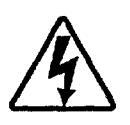
4. PERFORMANCE CHARTS
Cooling characteristics
Indoor unit KHS1232 Outdoor unit CH1232

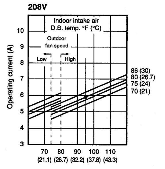
Outdoor intake air D.B. temp. °F (°C)

NOTE
.....Points of rating condition
Black dots in above charts indicate the following rating conditions.
Cooling: Indoor air temperature 80°F DB/67°F WB Outdoor air temperature 95°F DB
Heating characteristics


Outdoor intake air D.B. temp. °F (°C)
NOTE
Overload prevention operates to protect the air conditioner when the outdoor ambient temperature reaches an abnormally high level while in heating mode. (Refer to 5-5. Overload prevention)
........Points of rating condition
Black dots in above charts indicate the following rating conditions.
Heating: Indoor air temperature 70°F DB Outdoor air temperature 47°F DB/43°F WB
5. FUNCTION
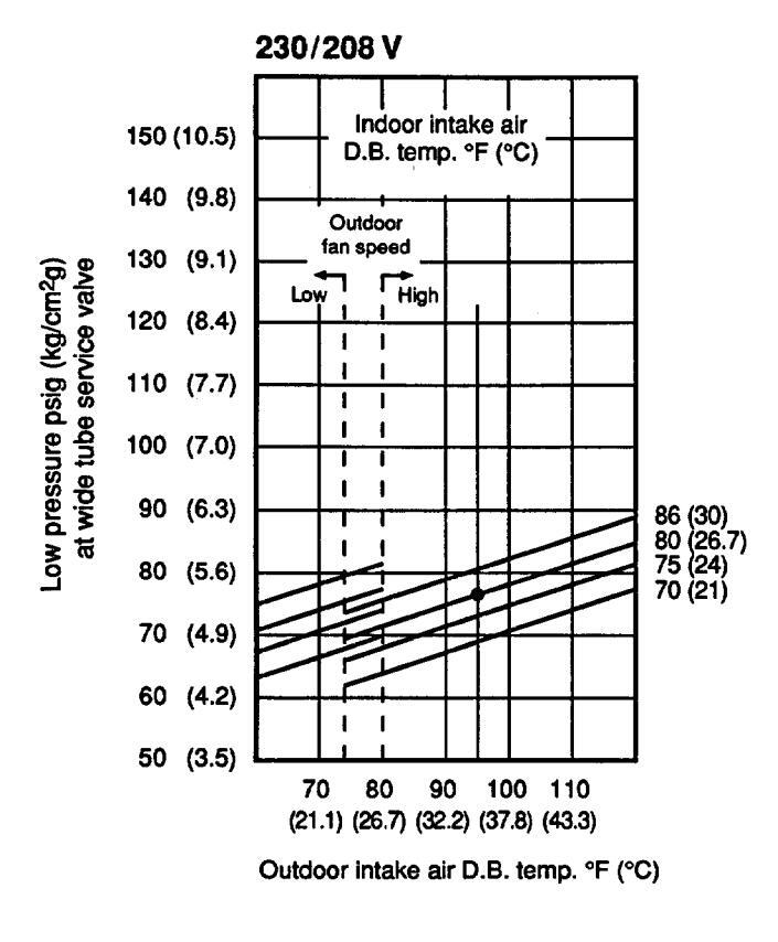
5-1. Room Temperature Control
- Room temperature control is obtained by cycling the compressor ON and OFF under control of the room temperature sensor in the remote control unit.
- The room temperature (and other information) is transmitted every 3 minutes by the remote control unit to the controller in the indoor unit.

- The control circuit will not attempt to turn the compressor ON until the compressor has been OFF for at least 3 minutes. To protect the compressor from stalling out when trying to start against the high side refrigerant pressure, the control circuit has a built-in automatic time delay to allow the internal pressure to equalize.
- As a protective measure, the control circuit switches the compressor OFF after 5 minutes or more of compressor operation.
- Thermo ON : When the room temperature is above T + 2°F (T°F is set temperature). Compressor ON
- Thermo OFF : When the room temperature is equal to or below set temperature T°F. Compressor OFF
Heating
- Room temperature control is obtained by cycling the compressor ON and OFF under control of the room temperature sensor in the remote control unit.
- The room temperature (and other information) is transmitted every 3 minutes by the remote control unit to the controller in the indoor unit.
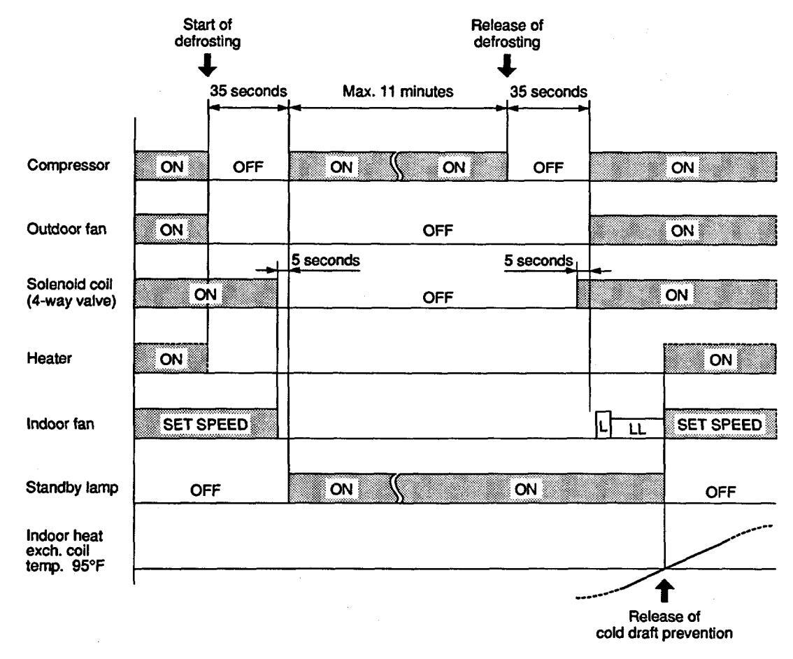
*1: Cold draft prevention
- The control circuit will not attempt to turn the compressor ON until the compressor has been OFF for at least 5 minutes. To protect the compressor from stalling out when trying to start against the high side refrigerant pressure, the control circuit has a built-in automatic time delay to allow the internal pressure to equalize.
- As a protective measure, the control circuit switches the compressor OFF after 5 minutes or more of compressor operation.
- Thermo ON : When the room temperature is below T 2°F (T°F is set temperature). Compressor ON
- Thermo OFF : When the room temperature is equal to or above set temperature T°F. Compressor OFF
5-2. Automatic Switching between Cooling and Heating
• When AUTO mode is selected, the microprocessor calculates the difference between the set temperature and the room temperature, and automatically switches to COOLING or HEATING mode to maintain the desired temperature.
Room temp. ≥ Set temp. → COOL Room temp. < Set temp. → HEAT
This means that if the room temperature is higher than or equal to the set temperature, COOLING operation begins. If the room temperature is lower than the set temperature. HEATING operation begins.
5-3. Heater Operation (Heating)
- The electric heater operates in Thermo ON at the time of initial start or when the room temperature is 4°F lower than the set temperature.
- When the air conditioner is thermo OFF, the heater is OFF at the same time.
- When the indoor outlet air temperature rises above 131°F, heater operation stops. It resumes operation when the indoor outlet air temperature falls below 113°F.
- When the outdoor temperature falls to around 10°F, the compressor stops but the electric heater continues to operate.
5-4. Freeze Prevention (Cooling)
- This function prevents freezing of the indoor heat exchange coil.
- When the compressor has been running for 10 minutes or more and the temperature of the indoor heat exchange coil falls below 30°F, the control circuit stops the compressor for at least 6 minutes.

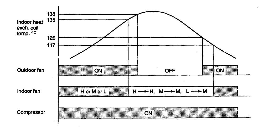
5-5. Overload Prevention (Heating)
- This function prevents overheating of the indoor heat exchange coil.
- When the temperature of the indoor heat exchange coil rises above 135°F, and if the indoor fan is L (low speed), then the fan speed changes from L (low speed) to M (medium speed).
- When the temperature of the indoor heat exchange coil rises above 138°F, the outdoor fan stops.
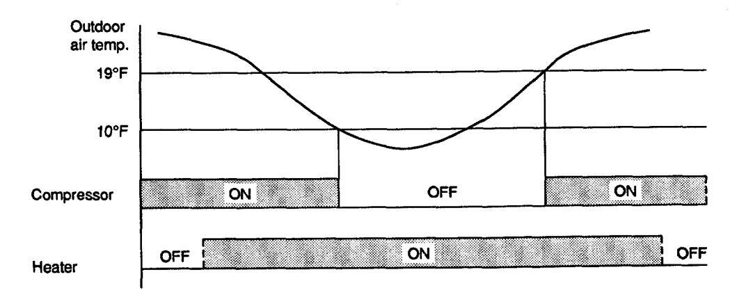
5-6. Change-over (Heating)
- This function protects the compressor from being damaged due to liquid back-flow.
- Low ambient operation during heating can cause the outdoor heat exchanger to become super-cooled which may result in liquid back-flow. To protect the compressor from this condition, the compressor stops if the outdoor temperature drops below 10°F. However, the indoor fan and the heater continue to operate even after the compressor has stopped.
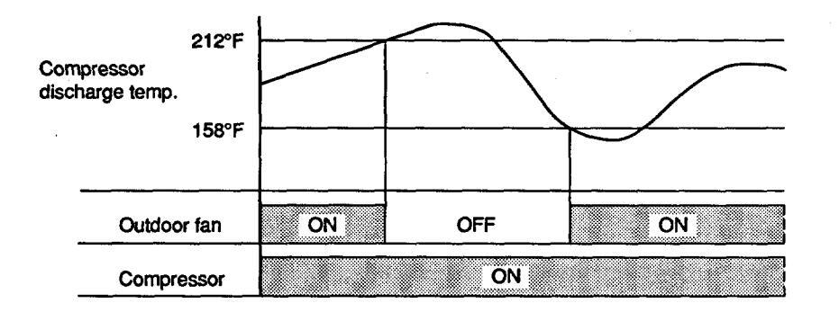
5-7. Compressor Overheating Prevention (Heating)
• This function protects the compressor from overheating using the outdoor fan.
5-8. Outdoor Fan Speed Control (Cooling)
- The outdoor fan speed switches automatically to LOW to prevent the indoor heat exchange coil from freezing due to low ambient temperature.
- If the outdoor air temperature falls below 74°F, the fan speed switches to LOW.
- If the outdoor air temperature rises above 80°F for 5 minutes or longer, the fan speed switches to HIGH.

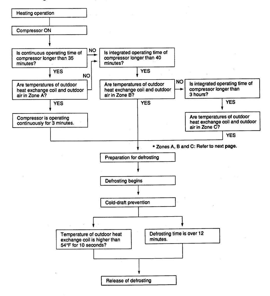
5-9. Defrosting Operation (Heating)
Defrosting Flowchart
Defrosting Mode Timing Chart
Defrosting Zone
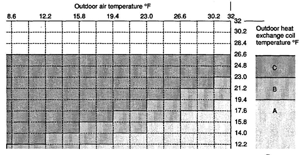
Zones
5-10. Self-Diagnostic Function
• When the following problems occur in the air conditioner, operation stops and the operation lamp in the indoor unit flashes.
At the same time, LED lamps on the PCB Ass'y in the indoor and outdoor units also flash. The combination of flashing LED lamps indicates the cause of the problem.
5-10-1. Fault with serial communication
- Fault in transmission between indoor and outdoor units.
- Error message appears on the PCB Ass'y after 3 minutes.
- To release this error, push the operation ON-OFF button again.
5-10-2. Locked compressor cut-off
- This function prevents the compressor from being damaged by overcurrent.
- The air conditioner stops when the current exceeds 17A for 2 seconds, repeating 3 times.
- To release this error, push the operation ON-OFF button again.
5-10-3. Compressor winding protection
• The air conditioner stops if the compressor discharge temperature rises above 239°F, repeating 2 times within 1 hour.

• To release this error, wait 15 minutes and push the operation ON-OFF button.
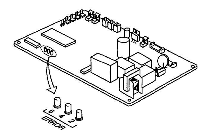
* Flashing of LED lamps on the PCB Ass'y
5-10-4. Open or short circuit of sensor (thermistor)
-
The following sensors are provided in the outdoor unit.
- TH1: Outdoor heat exchange coil temperature sensor
- TH2: Outdoor air temperature sensor
- TH3: Compressor discharge gas temperature sensor
- For checking the sensor fault, measure the sensor resistance.
5-10-5. Combination of LED lamps on PCB Ass'y
| Indoo | r unit | Outdoor unit | |||||
|---|---|---|---|---|---|---|---|
| Type of problem | LED lamp combination | LED lamp combination | |||||
| 24 | 25 | 26 | 27 | 2 | 4 | 6 | |
| Fault with serial communication | ☆ | ☆ | |||||
| Locked compressor cut-off | ☆ | ☆ | ☆ | ||||
| Compressor winding protection | ☆ | ☆ | ☆ | ☆ | |||
| Open or short circuit of sensor | ☆ | $ | |||||
☆: Flashing lamps
5-10-6. Arrangement of LED lamps on PCB Ass'y
• KHS1232

• CH1232
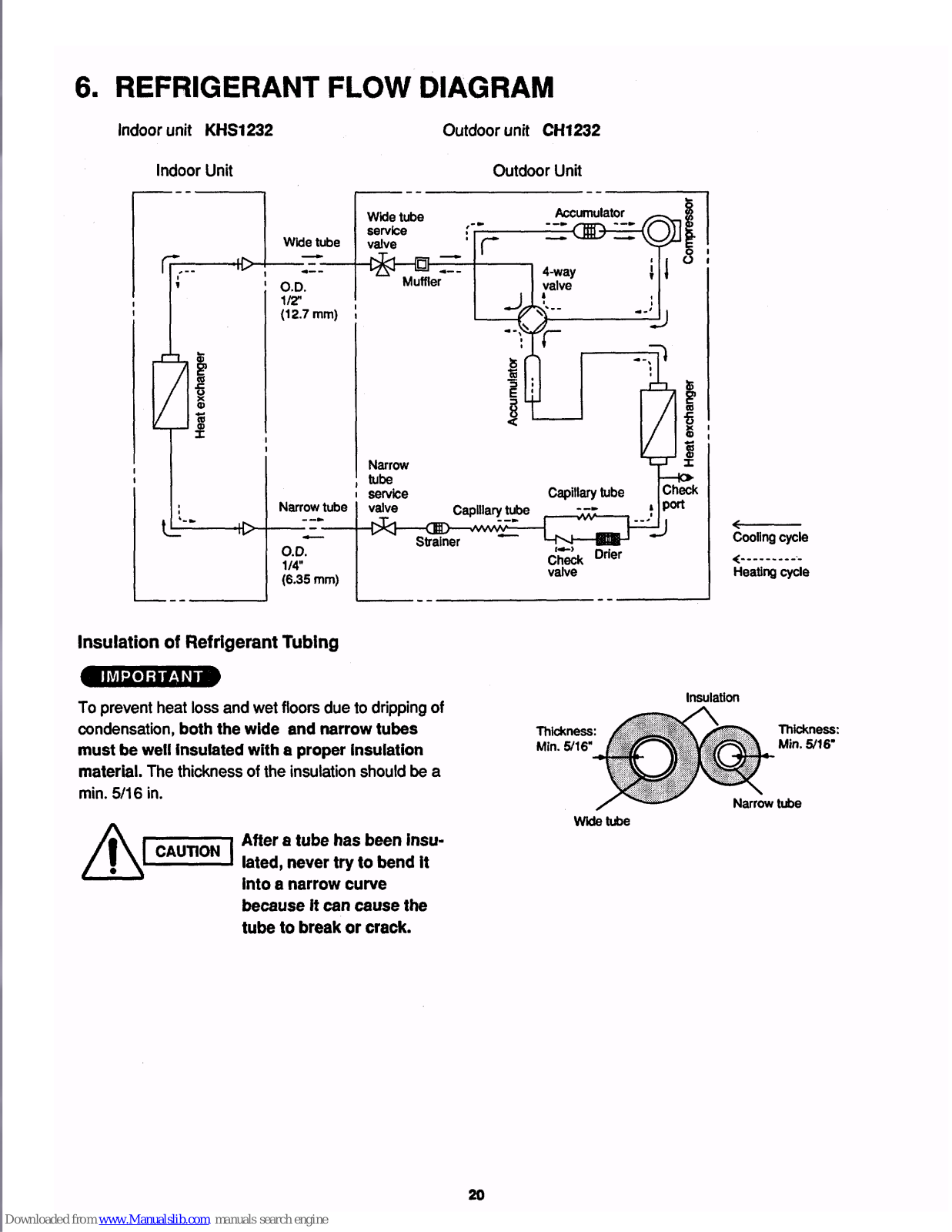
6. REFRIGERANT FLOW DIAGRAM
Indoor unit KHS1232
Outdoor unit CH1232
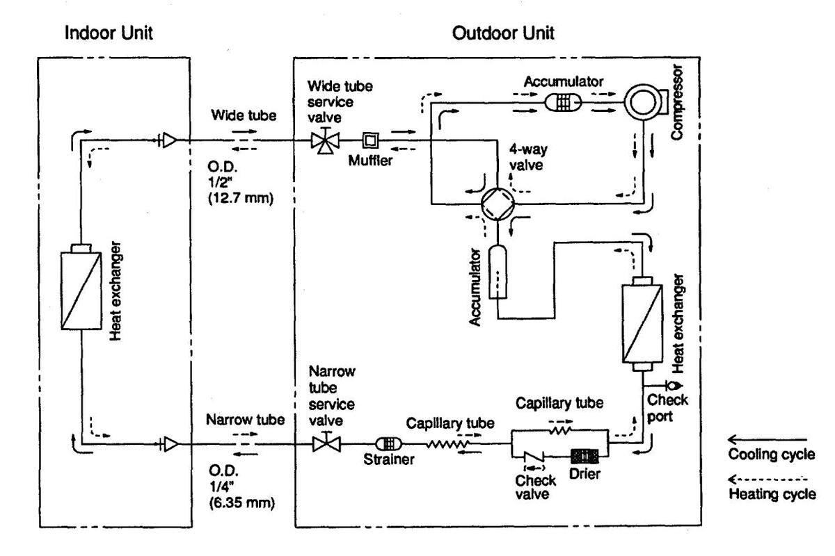
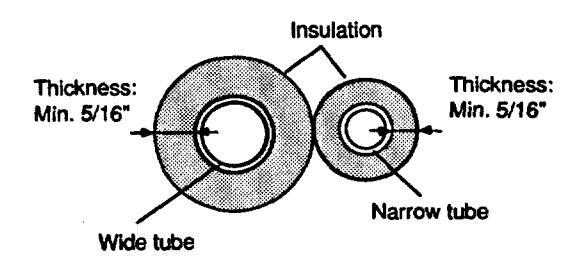
Insulation of Refrigerant Tubing
IMPORTANT
To prevent heat loss and wet floors due to dripping of condensation, both the wide and narrow tubes must be well insulated with a proper insulation material. The thickness of the insulation should be a min. 5/16 in.
After a tube has been insulated, never try to bend it into a narrow curve because it can cause the tube to break or crack.
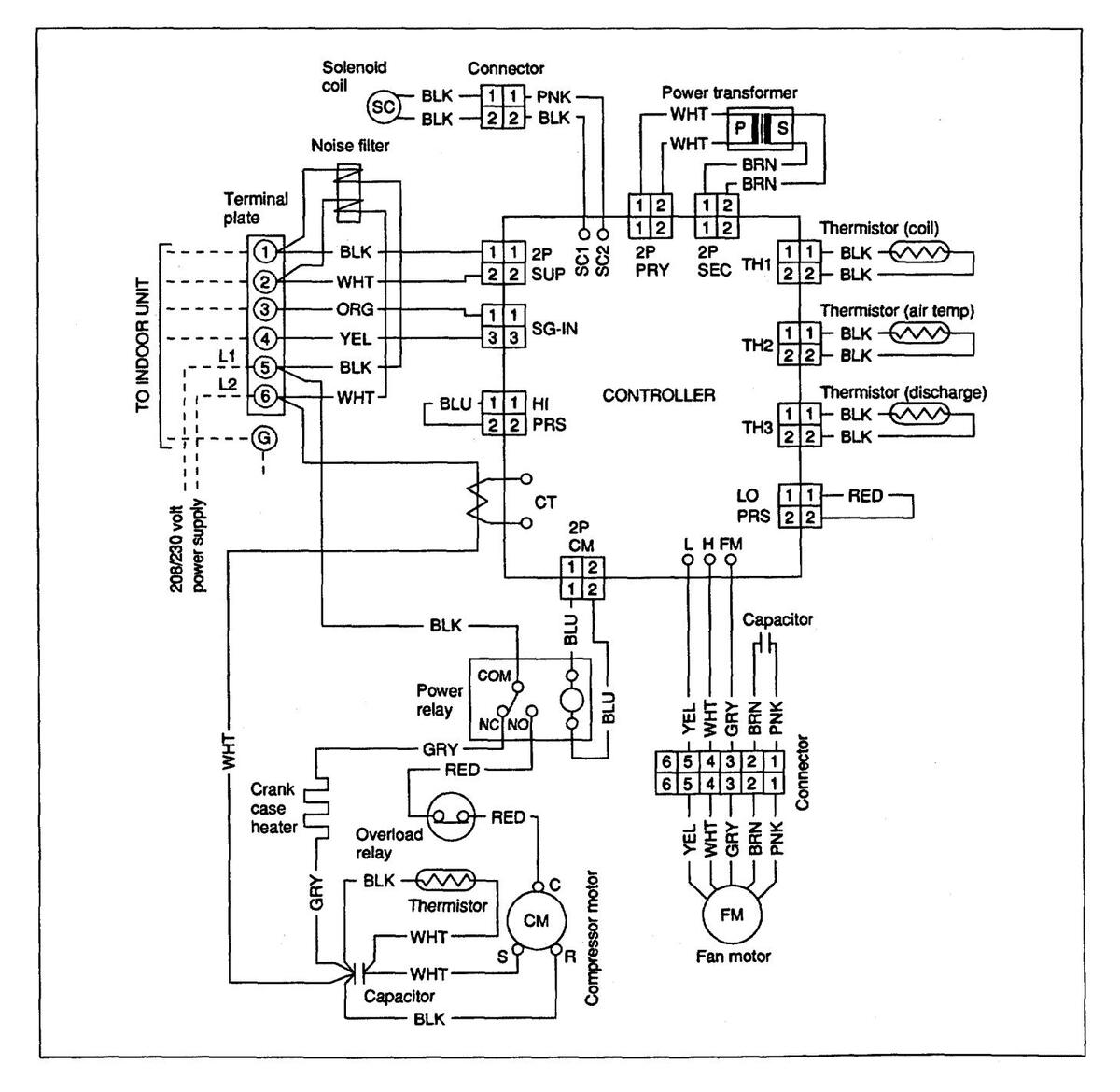
7. ELECTRIC WIRING DIAGRAMS
Indoor unit KHS1232

To avoid electrical shock hazard, be sure to disconnect power before checking, servicing and/or cleaning any electrical parts.

Outdoor unit CH1232
To avoid electrical shock hazard, be sure to disconnect power before checking, servicing and/or cleaning any electrical parts.
8. TROUBLESHOOTING
8-1. Check before and after troubleshooting
Hazardous voltage can cause ELECTRIC SHOCK or DEATH. Disconnect power or turn off circuit breaker before you start checking or servicing.
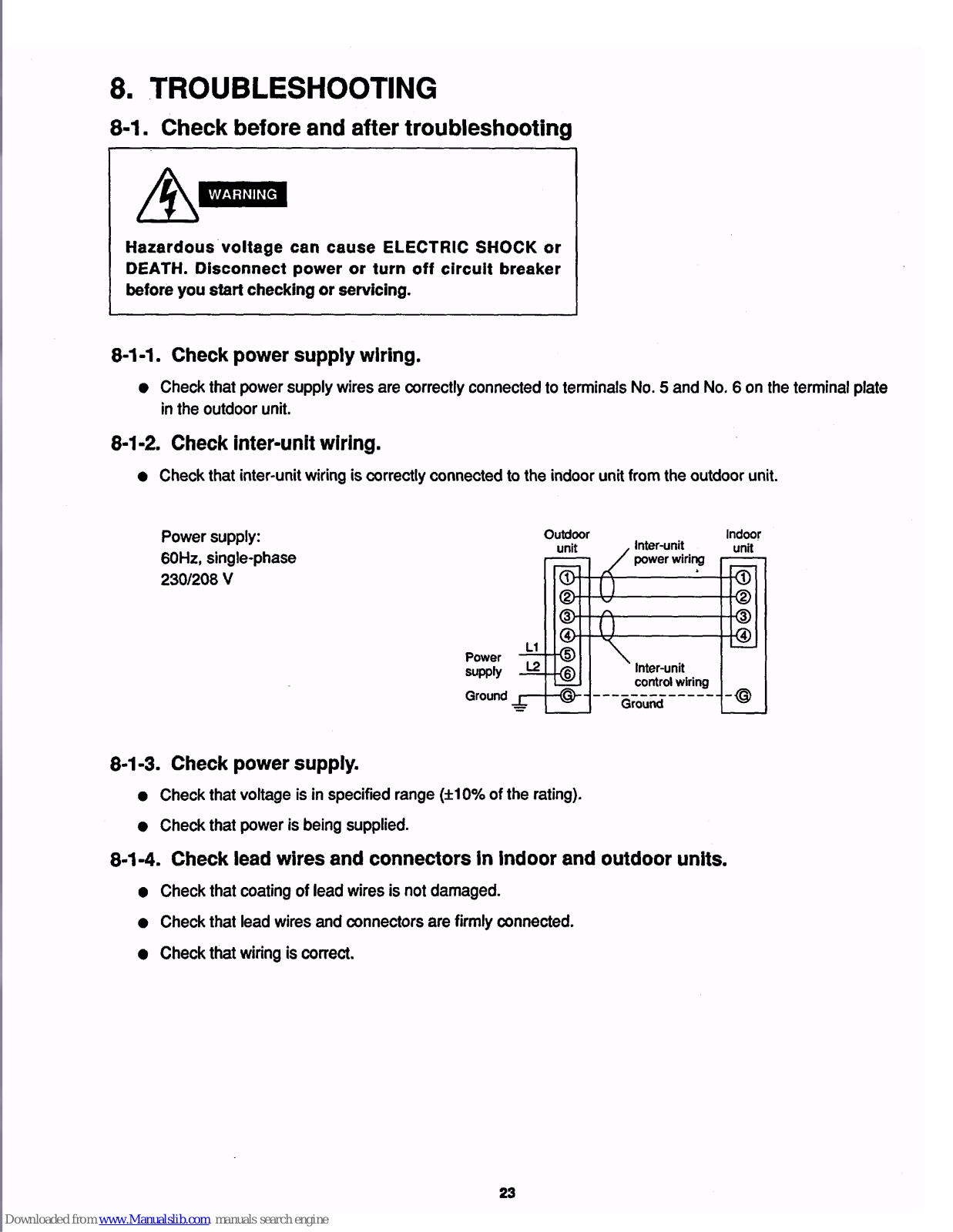
8-1-1. Check power supply wiring.
• Check that power supply wires are correctly connected to terminals No. 5 and No. 6 on the terminal plate in the outdoor unit.
8-1-2. Check inter-unit wiring.
• Check that inter-unit wiring is correctly connected to the indoor unit from the outdoor unit.

8-1-3. Check power supply.
- Check that voltage is in specified range (±10% of the rating).
- Check that power is being supplied.
8-1-4. Check lead wires and connectors in indoor and outdoor units.
- Check that coating of lead wires is not damaged.
- Check that lead wires and connectors are firmly connected.
- Check that wiring is correct.
8-2. Troubleshooting Flowchart
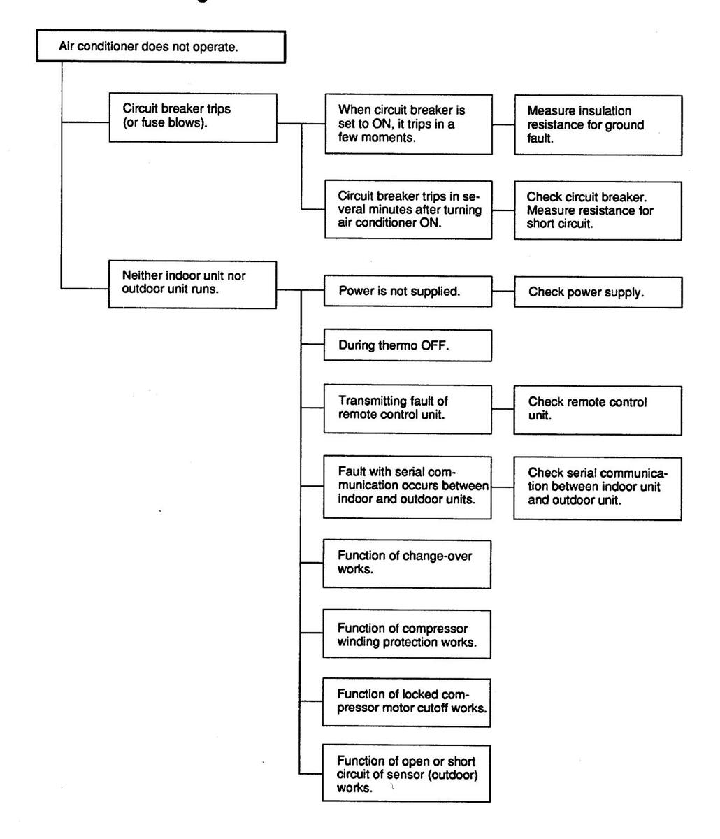
Troubleshooting Flowchart (cont'd)
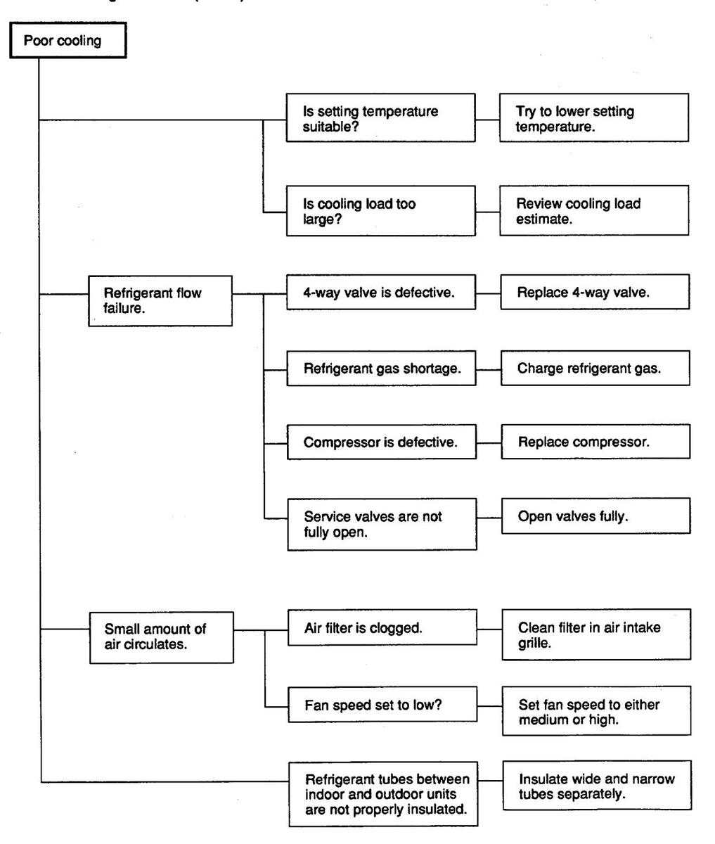
Troubleshooting Flowchart (cont'd)

8-3. Checking and Troubleshooting
8-3-1. Measure insulation resistance for ground fault.
If resistance value is 1MΩ or less, insulation is defective ("NO").

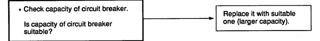
8-3-2. Check circuit breaker.
8-3-3. Measure resistance for short circuit.
Measure resistance of compressor motor winding.
8-3-4. Check power supply.
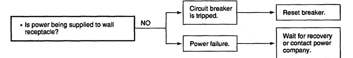
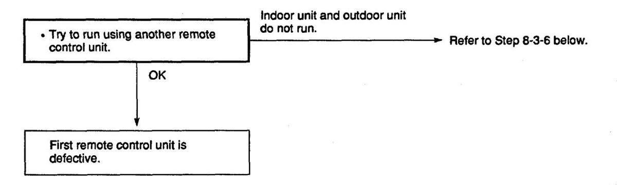
8-3-5. Check remote control unit.
8-3-6. Check OPERATION selector switch in indoor unit.

8-3-7. Check serial communication between indoor unit and outdoor unit.

• Check cause of fault.
(a) Check transformers in indoor and outdoor units.
Measure resistance of transformer windings.
(b) Check fuses on PCB Ass'y in indoor and outdoor units.

(c) PCB Ass'y in either indoor or outdoor unit is defective.
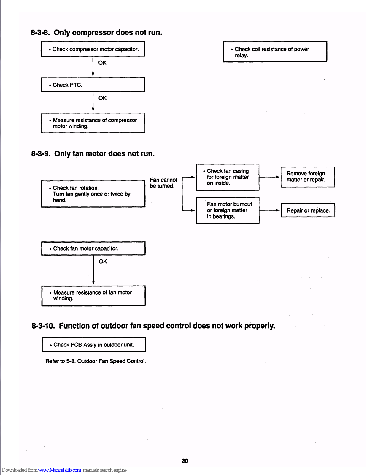
8-3-8. Only compressor does not run.
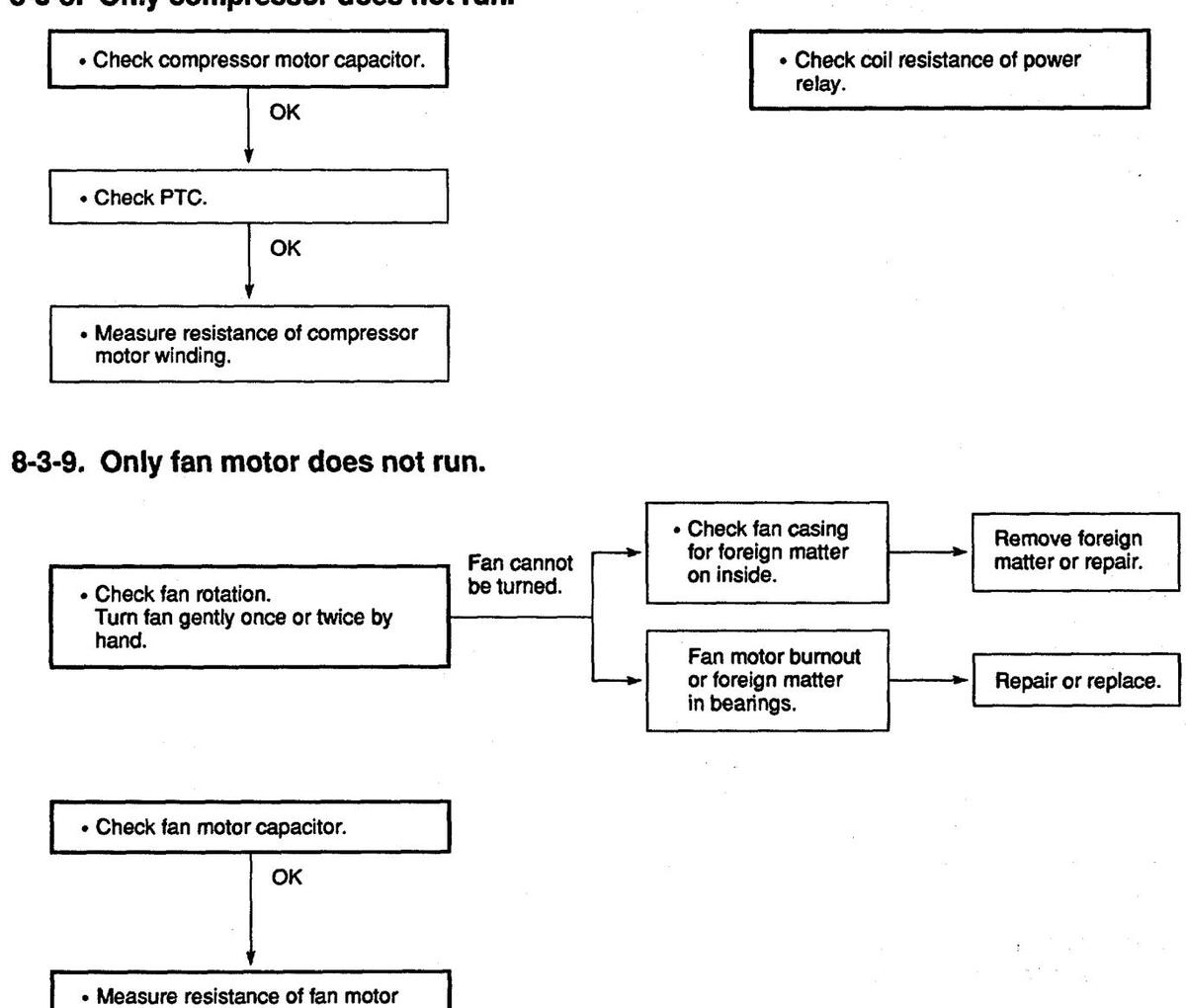
8-3-10. Function of outdoor fan speed control does not work properly.

Refer to 5-8. Outdoor Fan Speed Control.
winding.
9 CHECKING ELECTRICAL COMPONENTS
9.1 Measurement of Insulation Resistance
• The insulation is in good condition if the resistance exceeds 1MO
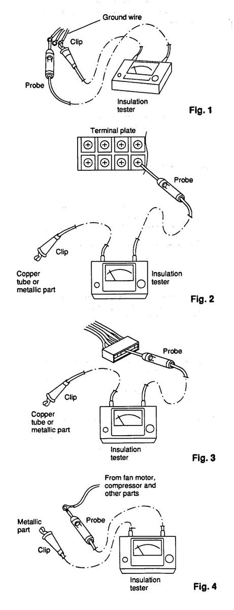
9-1-1. Power supply wires
Clamp the ground wire of the power supply wires with the lead clin of the insulation resistance tester and measure the resistance by placing a probe on either of the power wires. (Fig. 1)
Then measure the resistance between the ground wire and the other power wire. (Fig. 1)
9-1-2 Indoor unit
Clamp an aluminum plate fin or copper tube with the lead clip of the insulation resistance tester and measure the resistance by placing a probe on each terminal screw except where the ground line is connected on the terminal plate. (Fig. 2)
9-1-3. Outdoor unit
Clamp a metallic part of the unit with the lead clip of the insulation resistance tester and measure the resistance by placing a probe on each terminal screw where power supply lines are connected on the terminal plate, (Fig. 2)
9-1-4 Measurement of insulation resistance for electrical parts
Disconnect the lead wires of the desired electric part from terminal plate, PCB Ass'y, capacitor, etc. Similarly disconnect the connector. Then measure the insulation resistance. (Figs. 1 to 4)
Refer to Electric Wiring Diagram.
NOTE If the probe cannot enter the poles because the hole is too narrow then use a probe with a thinner pin.
9-2. Checking Continuity of Fuse on PCB Ass'y
Check for continuity using a multimeter as shown in Fig. 5.
NOTE
Method Used to Replace Fuse on PCB Ass'y
- 1. Remove the PCB Ass'y from the electrical component box.
- Pull the fuse from the metal clasp using pliers while heating the soldered leads on the back side of the PCB Ass'y with a soldering iron (30W or 60W). (Fig. 6)
- Remove the fuse ends one at a time. For replacement, insert a fuse of the same rating and solder it. (Allow time to radiate heat during soldering so that the fuse does not melt.)

When replacing the fuse, be sure not to break down the varistor.
9-3. Checking Motor Capacitor
Remove the lead wires from the capacitor terminals, and then place a probe on the capacitor terminals as shown in Fig. 7. Observe the deflection of the pointer, setting the resistance measuring range of the multimeter to the maximum value.
The capacitor is "good" if the pointer bounces to a great extent and then gradually returns to its original position.
The range of deflection and deflection time differ according to the capacity of the capacitor.

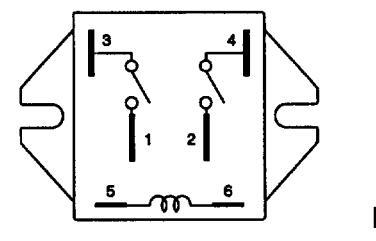
9-4. Appearance of Electrical Parts
(a) Heater Relay
G4E-2123T-US
Fia. 8
(b) Power Relay

Fig. 9
(c) Thermistor (PTC)
TDK 101YV
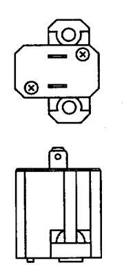
Fig. 10
(d) Thermostat (air blowout temperature)
CT-7L

APPENDIX INSTRUCTION MANUAL
Table of Contents
| F | > age |
|---|---|
| Installation Location | 3 |
| Electrical Requirements | 3 |
| Safety Instructions | 3 |
| Names of Parts | 4 |
| Using the Remote Control Unit | 8 |
| Operation with the Remote Control Unit | 9 |
| 1. Cooling | 9 |
| 2. Adjusting the Fan Speed | 10 |
| 3. Fan Only | 11 |
| 4. Heating | 12 |
| Operation without the Remote Control Unit | 13 |
| Setting the Timer | 14 |
| Adjusting the Airflow Direction | 15 |
| Care and Cleaning | 16 |
| Troubleshooting | 17 |
| Tips for Energy Saving | 17 |

Installation Location
- properly by a qualified installation technician in accordance with the Installation Instructions provided with the unit.
- Before installation, check that the voltage of the electric supply in your home or office is the same as the voltage shown on the nameplate.
- Do not install this air conditioner where there are fumes or flammable gases, or in an extremely humid space such as a green house.
- Do not install the air conditioner where excessively high heatgenerating objects are places.
- To protect the air conditioner from heavy corrosion, avoid installing the outdoor unit where salty sea water can splash directly onto it or in sulphurous air near a spa.
Electrical Requirements
- 1. All wiring must conform to the local electrical codes. Consult your dealer or a qualified electrician for details.
- 2. Each unit must be properly grounded with a ground (or earth) wire or through supply wiring.
- 3. Wiring must be done by a qualified electrician.
Power mains
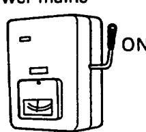
To warm up the system, power mains must be turned on at least five (5) hours before operation. Leave the power mains ON unless you will not be using this appliance for an extended period.
Power supply: 60 Hz, single-phase 230/208 VOLT
Safety Instructions
- Read this booklet carefully before using this air conditioner. If you still have any difficulties or problems, consult your dealer for help.
- This air conditioner is designed to give you comfortable room conditioners. Use this only for its intended purpose as described in these Instruction Manual.
- Never use or store gasoline or other flammable vapor or liquid near the air conditioner — it is very dangerous.
- This air conditioner has no ventilator for intaking fresh air from outdoors. You must open doors or windows frequently when you use gas or oil heating appliances in the same room, which consume a lot of oxygen from the air. Otherwise there is a risk of suffocation in an extreme case.
- Do not turn the air conditioner on and off from the power mains switch. Use the operation ON/OFF button.
- Do not stick anything into the air outlet of the air conditioner. This is dangerous because the fan is rotating at high speed.
- Do not let children play with the air conditioner.
- Do not cool or heat the room too much if babies or invalids are present.


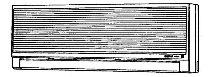
Names of Parts
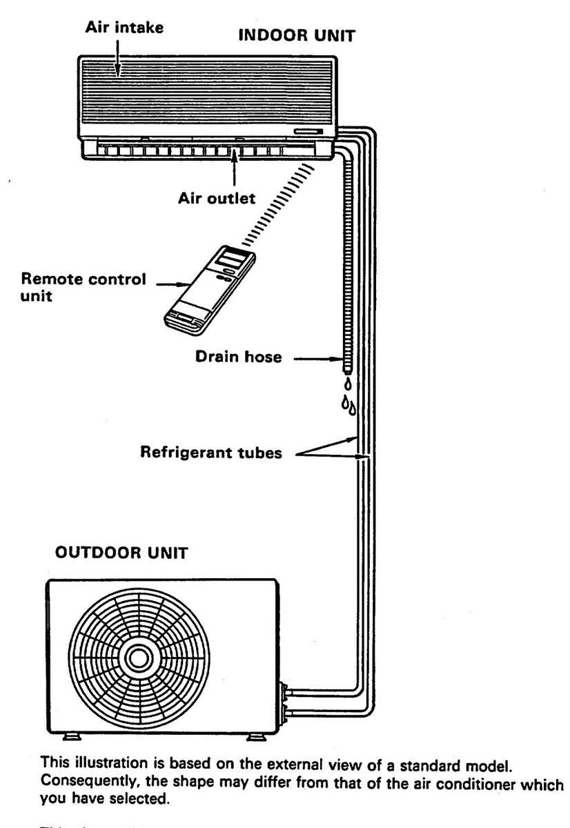
This air conditioner consists of an indoor unit and an outdoor unit. You can control the air conditioner with the remote control unit.
Air Intake
NOTE:
Air Outlet Remote Control Unit
Refrigerant Tubes
Drain Hose Outdoor (Condensing) Unit
1
Air from the room is drawn into this section and passes through air filters which remove dust.
Conditioned air is blown out of the air conditioner through the air outlet. The wireless remote control unit controls power ON/OFF, operation mode selection, temperature, fan speed, timer setting, and air sweeping. The indoor and outdoor units are connected by copper tubes through which refrigerant gas flows.
Moisture in the room condenses and drains off through this hose. The outdoor unit contains the compressor, fan motor, heat exchanger coil, and other electrical components.
Unit Display and Operation Selector
INDOOR UNIT
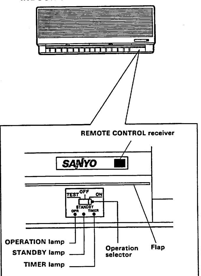
REMOTE CONTROL receiver OPERATION lamp STANDBY lamp
TIMER lamp Operation selector ON position
OFF position

TEST position
This section picks up infrared signals from the remote control unit (transmitter).
This lights when the system is in the continuous COOL or FAN mode.
This lamp lights during warm up period for heating and when the system is defrosting. To keep a constant room temperature, the air conditioner continues to supply a gentle breeze during warm up or when the heating operation is paused by the thermostat.
This lamp lights when the system is being controlled by the timer.
This position is for operating the air conditioner with the wireless remote control unit. Set the selector normally in this position. Switch the selector to the OFF position if you are not going to use the air conditioner for a few days or longer.
The OFF position does not disconnect the power. Use the main power switch to turn off power completely.
This position is used only when servicing the air conditioner, so don't leave the selector in this position.
Remote Control Unit

Remote Control Unit (continued)
| SWEEP button |
When you press this button, the (SWEEP) mark will appear at the lower left of
the display, and the flap in the air outlet starts moving up and down to deliver air over the sweep range set. To stop sweeping, just press the SWEEP button again. |
||
|---|---|---|---|
| MODE selector switch |
FAN:
COOL: HEAT: AUTO: |
The air conditioner works only as a circulation fan.
The air conditioner makes the room cooler. The air conditioner makes the room warmer. When this setting is selected, the air conditioner calculates the difference between the thermostat setting and the room temperature and automatically switches to the "cool" or "heat" mode as appropriate. |
|
| Timer selector switch |
NORM.:
OFF: ON: PROGRAM: |
The timer does not operate.
The air conditioner stops at the set time. The air conditioner starts at the set time. The air conditioner stops and starts, or starts and stops, at the set times every day. |
|
| Fan speed selector switch |
AUTO:
HIGH: MED.: LOW: |
The air conditioner automatically decides the fan speeds.
High speed for fast cooling Medium speed Low speed |
|
| SENSOR | A temperature temperature. | e sensor inside the remote control unit senses the room | |
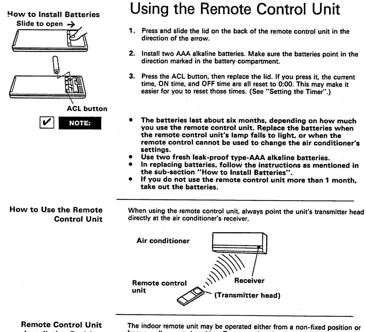
Installation Position

The indoor remote unit may be operated either from a non-fixed position or from a wall-mounted position. To ensure that the air conditioner operates correctly, do not install the remote control unit in the following places:
- In direct sunlight
- Behind a curtain or other places where it is covered
- More than 26 ft. away from the air conditioner
- In the path of the air conditioner's airstream
- Where it may become extremely hot or cold
- Where it may be subject to electrical or magnetic noise
1. If Non-fixed Position
Raise the rear plate of the remote control unit mounting cradle and insert the remote control unit. The unit can be used either in that position (placed on a table, for instance) or held in the hand.
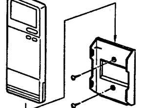
2. If Wall-mounted Fixed Position
Install the remote control unit at a convenient location on a nearby wall. However, before attaching the remote control unit mounting cradle, check that the remote control unit can operate from the desired wall position.
Operation with the Remote Control Unit
-
NOTE:
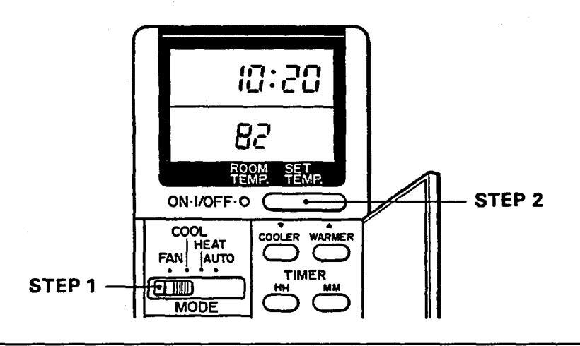
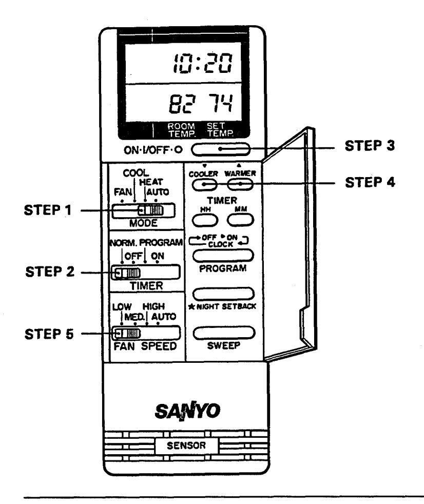
- 1. Cooling
Check that the circuit breaker on the power panel is turned on and the operation selector of the indoor unit is in the ON position.
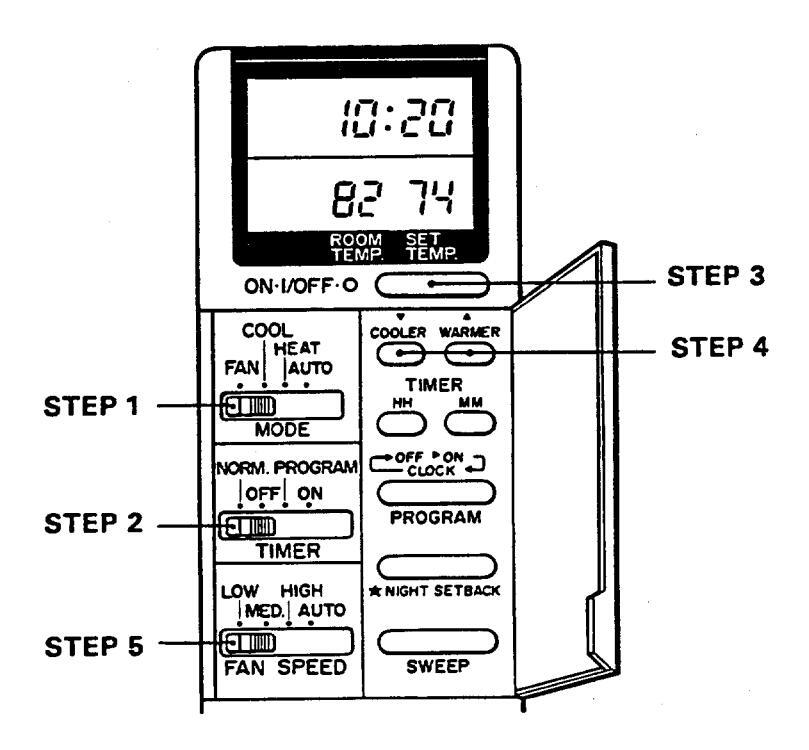
- STEP 1: Set the MODE selector switch to COOL.
- STEP 2: Set the timer selector switch to NORM.
- STEP 3: Press the ON/OFF operation button.
- STEP 4: Press the COOLER or WARMER button to set a cooler or warmer temperature.
Each time you press these buttons, the set temperature varies by 2° F.
84° F max.
64° F min.
STEP 5: Set the fan speed selector switch to the setting you want.
To stop the air conditioner, press the ON/OFF operation button again.
- Choose the best position in the room for the remote control unit, which also acts as the sensor for room comfort and transmits the operating instructions. Once you've found this best position, always keep the remote control unit there.
- This appliance has a built-in 3-minute time delay circuit to ensure reliable operation. If the operation button is pressed, the compressor will start running after three minutes. In the event of power failure, the unit will stop. When the power is applied, the unit will re-start automatically after 3 minutes.
- To prevent the appliance from malfunctioning, do not set any selector switch between two indicated positions. Make sure that it clicks into position.


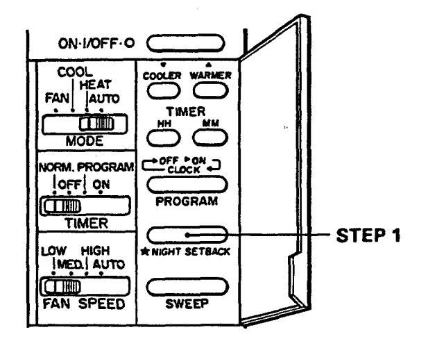
Night Setback Mode in Cooling
STEP 1: Press the NIGHT SETBACK button in cooling. The _____ mark appears at the lower left of the display. Press the NIGHT SETBACK button again to release the night setback function. This button has no effect in the FAN mode.
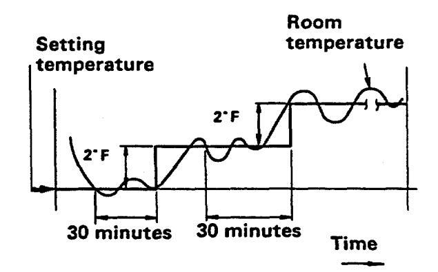
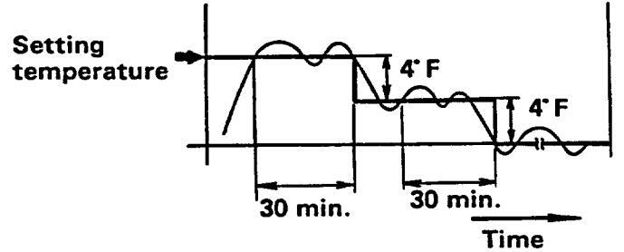
What does the Night Setback mode mean?
In this mode, the air conditioner will cool the room to the set temperature, and then the thermostat will make the unit pause. After about 30 minutes, the air conditioner will automatically raise the set temperature by 2° F. When the room temperature reaches the newly set value, the thermostat will cause the unit to pause. After about 30 minutes the temperature will again be raised by 2° F. This enables you to save energy without sacrificing comfort. This function is convenient when gentle cooling is needed.
2. Adjusting the Fan Speed
A. Automatic
STEP 1: Simply set the FAN SPEED selector to the "AUTO" position.
A microcomputer in the air conditioner automatically controls the fan speed when the AUTO mode is selected. When the air conditioner starts operating, the difference between the room temperature and the set temperature is detected by the microcomputer which then automatically switches the fan speed to the most suitable level.
Cooling mode:
| When difference between room temperature and set temperature is | FAN SPEED |
|---|---|
| 4°F and over | High |
| Between 4° F and 2° F | Medium |
| Below 2°F | Low |
Heating mode:
| When difference between | FAN SPEED |
|---|---|
| room temperature and set | |
| temperature is | |
| 2°F and over | High |
| Below 2° F | Medium |
B. Manual
If you want to adjust fan speed manually during cooling, just set the FAN SPEED selector as desired. [HIGH. MED., or LOW]
3. Fan Only
If you want to circulate air without any temperature control, follow these steps:
- STEP 1: Set the MODE selector switch to FAN.
- STEP 2: Press the ON/OFF operation button.
4. Heating
| STEFT. Set the MODE selector switch to hEAT. | STEP 1: | Set the | MODE | selector | switch | to | HEAT. |
|---|
- STEP 2: Set the timer selector switch to NORM.
- STEP 3: Press the ON/OFF operation button.
- STEP 4: Press the COOLER or WARMER button to set a cooler or warmer temperature.
Each time you press these buttons, the set temperature varies by 2° F.
84° F max.
64" F min.
STEP 5: Set the fan speed selector switch to the setting you want. To stop the air conditioner, press the ON/OFF operation button again.
- Choose the best position in the room for the remote control unit, which also acts as the sensor for room comfort and transmits the operating instructions. Once you've found this best position, always keep the remote control unit there.
- This appliance has a built-in 3-minute time delay circuit to ensure reliable operation. If the operation button is pressed, the compressor will start running after three minutes. In the event of power failure, the unit will stop. When the power is applied, the unit will re-start automatically after 3 minutes.
- To prevent the appliance from malfunctioning, do not set any selector switch between two indicated positions. Make sure that it clicks into position.


If the outdoor temperature is extremely low, it is recommended to use another heating appliance:
When the outdoor temperature falls to around 10° F, the compressor stops. In this case, to prevent room from freezing, use another heating appliance.

Night Setback Mode in Heating
STEP 1: Press the NIGHT SETBACK button in cooling. The _____ mark appears at the lower left of the display. Press the NIGHT SETBACK button again to release the night setback function. This button has no effect in the FAN mode.
What does the Night Setback mode mean?
In this mode, the air conditioner will heat the room to the set temperature, and then the thermostat will make the unit pause. After about 30 minutes, the air conditioner will automatically lower the set temperature by 4° F. When the room temperature reaches the newly set value, the thermostat will cause the unit to pause. After about 30 minutes the temperature will again lowered by 4° F. This enables you to save energy without sacrificing comfort. This function is convenient when gentle heating is needed.
INDOOR UNIT

Operation without the Remote Control Unit
If you have lost the remote control unit or it has trouble, follow the steps below.
1. When the air conditioner is stopped.
If you want to turn on the air conditioner, switch the operation selector to the OFF position, and then to the ON position.

The set temp. and fan speed are automatically set at the latest selection before stopping.
2. When the air conditioner is running.
If you want to turn off the air conditioner, switch the operation selector to the OFF position.
1) How to set the present time
2) How to set the OFF time
3) How to set the ON time

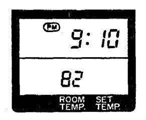
Setting the Timer
(Example) To set to 9:10 p.m.
| Operation | Indication |
|---|---|
|
1. Press the PROGRAM button three times.
The time indication alone flashes. |
Flashing |
|
Flashing |
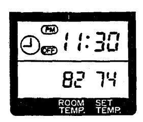
(Example) To stop the air conditioner at 11:30 p.m.
| 1. Press the PROGRAM button once. The timer OFF and time indications flash. | Flashing |
|---|---|
|
Flashing |
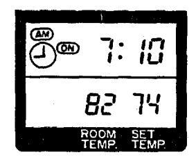
(Example) To start operation at 7:10.
|
Flashing |
|
Flashing |
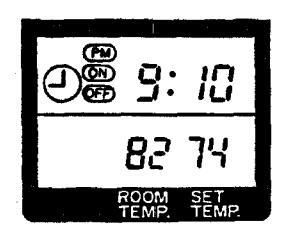
(Example) To start operation at 7:10 and stop the air conditioner at 11:30 p.m.
|
|
|---|---|
|
Power failure during timer operation
If power failure occurs, the time counted up to that point will become void. After the power is applied, the timer newly starts counting at the set time.
Adjusting the Airflow Direction


Casing and Grille (Indoor Unit)
Care and Cleaning
For safety, be sure to turn the air conditioner off and also to disconnect the power before cleaning. Do not pour water on the indoor unit to clean it. This will damage
2. Do not pour water on the indoor unit to clean it. This will damage the internal components and cause an electric shock hazard.
Clean the casing and grille of the indoor unit with a vacuum cleaner brush, or wipe them with a clean, soft cloth.
If these parts are stained, use a clean cloth moistened with a mild liquid detergent. When cleaning the grille, be careful not to force the vanes out of place.
- 1. Never use solvents, or harsh chemicals when cleaning the indoor unit. Do not wipe the plastic casing using very hot water.
- Some metal edges and the fins are sharp and may cause injury if handled improperly; be especially careful when you clean these parts.
- The internal coil and other components of the outdoor unit must be cleaned every year. Consult your dealer or service centre.
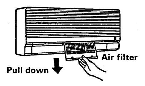

Air Filter
The air filter behind the air intake grille should be checked and cleaned at least once every two weeks.
How to remove the filter
- 1. Move the flap on the air outlet grille to its lowest position.
- 2. Hold the air filter by the tab at the bottom, and pull downward.
Use a vacuum cleaner to remove light dust. If there is sticky dust on the filter, wash the filter in lukewarm, soapy water, rinse it in clean water, and dry it. When replacing the filter, make sure that the FRONT mark is facing you.
Troubleshooting
If your air conditioner does not work properly, first check the following points before requesting service. If it still does not work properly, contact your dealer or service centre.
| Trouble | Possible Cause | Remedy |
|---|---|---|
|
Air conditioner does not
run at all |
1. Power failure | 1. Restore power |
| 2. Leakage breaker tripped | 2. Contact service centre | |
| 3. Line voltage too low | 3. Consult with electrician or dealer | |
| 4. Operation button is OFF | 4. Press the button again | |
| 5. Batteries in remote control unit have run down | 5. Replace batteries | |
| Compressor runs but soon stops | 1. Obstruction in front of condenser coil | 1. Remove obstruction |
|
Poor cooling (or heating)
performance |
1. Dirty or clogged air filter | 1. Clean air filter to improve airflow |
| 2. Heat source or many people in room | 2. Eliminate heat source if possible | |
| 3. Doors and/or windows are open | 3. Shut them to keep the heat out | |
| 4. Obstacle near air intake or air discharge port | 4. Remove it to ensure good airflow | |
| 5. Thermostat is set too high for cooling (or too low for heating) | 5. Set the temperature lower | |
| 6. (Outdoor temperature is too low) | 6. (Try to use any back-up heater) | |
| 7. (Defrosting system does not work) | 7. (Consult your dealer) |

- Tips for Energy Saving
- Block the air intake and outlet of the unit. If it is obstructed, the unit will not work well, and may be damaged. Let direct sunlight into the room. Use sunshades, blind or curtains. If the
- ✔ Do:
- to cool the room. Always try to keep the air filter clean. (Refer to "Care and Cleaning"). A clogged filter will impair the performance of the unit.
walls and ceiling of the room are warmed by the sun, it will take longer
To prevent conditioned air from escaping, keep windows, doors and any other openings closed.
For Parts or Service Contact SANYO FISHER SERVICE CORPORATION 1200 West Artesia Blvd., Compton, California, 90220, USA 50 Beth Nealson Drive, Toronto, Ontario, M4H 1M6, CANADA
Nov. / '95 / 1350 Printed in the U.S.A.


 Loading...