

Page 1
TECHNICAL DATA
&
SERVICE MANUAL
XH2672R / CH2672R, C2672R
XH3672R / CH3672R, C3672R
XH4272R / CH4272R, C4272R
TH2672R / CH2672R, C2672R
TH3672R / CH3672R, C3672R
TH4272R / CH4272R, C4272R
THH2672R / CH2672R
THH3672R / CH3672R
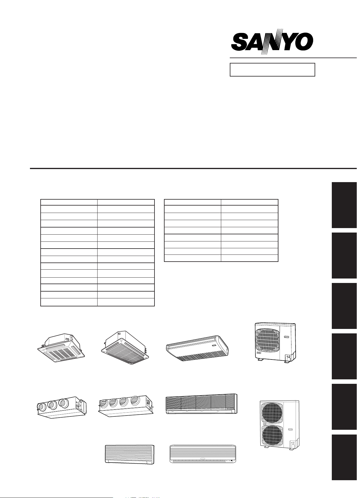
SPLIT SYSTEM AIR CONDITIONER
INDOOR MODEL No. PRODUCT CODE No.
XH2672R 854 028 32
XH3672R 854 028 33
XH4272R 854 031 89
TH2672R 854 028 35
TH3672R 854 028 36
TH4272R 854 031 90
THH2672R 854 028 38
THH3672R 854 028 39
KH2672R 854 028 28
KH3072R 854 028 29
KH3672R 854 028 30
KHH2672R 854 028 31
UH2672R 854 028 40
UH3672R 854 028 41
Indoor Unit Outdoor Unit
OUTDOOR MODEL No. PRODUCT CODE No.
FILE NO.
KH2672R / CH2672R, C2672R
KH3072R / CH3072R, C3072R
KH3672R / CH3672R, C3672R
KHH2672R / CH2672R
UH2672R / CH2672R, C2672R
UH3672R / CH3672R, C3672R
CH2672R 854 028 20
CH3072R 854 028 21
CH3672R 854 028 22
CH4272R 854 031 87
C2672R 854 028 24
C3072R 854 028 25
C3672R 854 028 26
C4272R 854 031 88
Section
1
2
3
XH2672R XH3672R
XH4272R
UH2672R
85464849248002 REFERENCE NO. SM831148-2
UH3672R
KHH2672R KH2672R
TH2672R, THH2672R
TH3672R, THH3672R
TH4272R
KH3072R
KH3672R
CH2672R, C2672R
CH3072R, C3072R
CH3672R, C3672R
CH4272R, C4272R
4
5
6
Page 2

Page 3
Important
Please Read Before Starting
This air conditioning system meets strict safety and operating
standards. As the installer or service person, it is an important
part of your job to install or service the system so it operates
safely and efficiently.
For safe installation and trouble-free operation, you must :
● Carefully read this instruction booklet before beginning.
● Follow each installation or repair step exactly as shown.
● Observe all local, state, and national electrical codes.
● Pay close attention to all warning and caution notices
given in this manual.
This symbol refers to a hazard or
unsafe practice which can result
in severe personal injury or death.
This symbol refers to a hazard or
CAUTION
unsafe practice which can result
in personal injury or product or
property damage.
If Necessary, Get Help
These instructions are all you need for most installation sites
and maintenance conditions. If you require help for a special
problem, contact our sales/service outlet or your certified
dealer for additional instructions.
In Case of Improper Installation
The manufacturer shall in no way be responsible for improper
installation or maintenance service, including failure to follow
the instructions in this document.
SPECIAL PRECAUTIONS
When Wiring
.............................................................................................
ELECTRICAL SHOCK CAN CAUSE SEVERE
PERSONAL INJURY OR DEATH. ONLY A
QUALIFIED, EXPERIENCED ELECTRICIAN
SHOULD ATTEMPT TO WIRE THIS SYSTEM.
●
Do not supply power to the unit until all wiring and tubing are
completed or reconnected and checked.
●
Highly dangerous electrical voltages are used in this system.
Carefully refer to the wiring diagram and these instructions
when wiring. Improper connections and inadequate
grounding can cause accidentaly injury or death.
●
Ground the unit following local electrical codes.
●
Connect all wiring tightly. Loose wiring may cause overheating at connection points and a possible fire hazard.
When Transporting
...............................................................................................
Be careful when picking up and moving the indoor and outdoor
units. Get a partner to help, and bend your knees when lifting
to reduce strain on your back. Sharp edges or thin aluminum
fins on the air conditioner can cut your fingers.
When Installing
.............................................................................................
…In a Room
Properly insulate any tubing run inside a room to prevent
“sweating” that can cause dripping and water damage to walls
and floors.
…In Moist or Uneven Locations
Use a raised concrete pad or concrete blocks to provide a
solid, level foundation for the outdoor unit. This prevents water
damage and abnormal vibration.
…In an area with High Winds
Securely anchor the outdoor unit down with bolts and a metal
frame. Provide a suitable air baffle.
…In a Snowy Area (for Heat Pump-type Sys-tems)
Install the outdoor unit on a raised platform that is higher than
drifting snow. Provide snow vents.
When Connecting Refrigerant Tubing
.............................................................................................
●
Ventilate the room well, in the event that refrigerant gas
leaks during the installation. Be careful not to allow contact
of the refrigerant gas with a flame as this will cause the
generation of poisonous gas.
●
Keep all tubing runs as short as possible.
●
Use the flare method for connecting tubing.
●
Apply refrigerant lubricant to the matching surfaces of the
flare and union tubes before connecting them, then tighten
the nut with a torque wrench for a leak-free connection.
●
Check carefully for leaks before starting the test run.
NOTE
Depending on the system type, liquid and gas lines may be
either narrow or wide. Therefore, to avoid confusion the
refrigerant tubing for your particular model is specified as either
“narrow” or “wide” rather than as “liquid” or “gas”.
When Servicing
..............................................................................................
●
Turn the power OFF at the main power box (mains) before
opening the unit to check or repair electrical parts and
wiring.
●
Keep your fingers and clothing away from any moving parts.
●
Clean up the site when installation is finished. Check that no
metal scraps or bits of wiring have been left inside the unit.
CAUTION
●
Ventilate any enclosed areas when installing or testing the
refrigeration system. Contact of refrigerant gas with fire or
heat can produce poisonous gas.
●
Confirm after installation that no refrigerant gas is leaking. If
the gas comes in contact with a burning stove, gas water
heater, electric room heater or other heat source, it can
cause the generation of poisonous gas.
SM831148
i
Page 4

Contents
Section 1: SPECIFICATIONS ................................................................................................. I-1
1-1 Unit Specifications .......................................................................................... I-2
1-2 Major Component Specifications .................................................................. I-27
1-3 Other Component Specifications .................................................................. I-47
1-4 Dimensional data .......................................................................................... I-63
1-5 Refrigerant Flow Diagram ............................................................................. I-74
1-6 Operating Range .......................................................................................... I-75
1-7 Heating Capacity .......................................................................................... I-76
1-8 Noise Criterion Curves.................................................................................. I-77
1-9 Increasing the Fan Speed ............................................................................. I-82
1-10 Air throw distance chart ................................................................................ I-83
1-11 Installation Instructions.................................................................................. I-86
1-12 Electrical Wiring ............................................................................................I-98
1-13 Using Wireless Remote Controller with Wall-mounted Indoor Unit ............. I-102
Section 2: PROCESSES AND FUNCTIONS......................................................................... II-1
2-1 Room Temperature Control ............................................................................ II-2
2-2 Cold Draft Prevention (Heating Cycle) ........................................................... II-4
2-3 Automatic Fan Speed (Indoor Unit) ................................................................ II-5
2-4 Control Functions........................................................................................... II-6
2-5 Outdoor Unit Control PCB .............................................................................. II-9
2-6 Outdoor Unit Control PCB (CR-CH4272R) .................................................. II-10
Section 3: ELECTRICAL DATA ............................................................................................ III-1
3-1 Indoor Units................................................................................................... III-2
3-2 Outdoor Units .............................................................................................. III-16
Section 4: SERVICE PROCEDURES ..................................................................................IV-1
4-1 Meaning of Alarm Messages.........................................................................IV-2
4-2 Symptoms and Parts to Inspect .....................................................................IV-5
4-3 Details of Alarm Messages ........................................................................... IV-8
4-4 Table of Thermistor Characteristics .............................................................IV-14
Section 5:
Section 6: TEST RUN .......................................................................................................... VI-1
OUTDOOR UNIT MAINTENANCE REMOTE CONTROL ...............................................
5-1 Overview ....................................................................................................... V-2
5-2 Functions ...................................................................................................... V-2
5-3 Normal Display Operations and Functions ................................................... V-3
5-4 Monitoring Operations: Display of Indoor Unit and Outdoor Unit Sensor
Temperatures ................................................................................................ V-6
5-5 Monitoring the Outdoor Unit Alarm History: Display of Outdoor Unit
Alarm History ................................................................................................ V-7
5-6 Setting Modes: Setting the Outdoor Unit EEPROM ....................................... V-7
6-1 Preparing for Test Run ................................................................................. VI-2
6-2 Caution ........................................................................................................ VI-3
6-3 Test Run Procedure ..................................................................................... VI-3
6-4 Items to Check Before the Test Run ............................................................. VI-4
6-5 Test Run Using the Remote Controller......................................................... VI-4
6-6 Precautions .................................................................................................. VI-4
6-7 Table of Self-Diagnostic Functions and Corrections (X, T, U, K Type) .......... VI-5
6-8 Examples of Wiring Diagrams ...................................................................... VI-6
V-1
Page 5

1. Specifications
1. SPECIFICATIONS
1-1 Unit Specifications ......................................................................................................... I-2
1-2 Major Component Specifications ............................................................................... I-27
1-3 Other Component Specifications ............................................................................... I-47
1-4 Dimensional data ......................................................................................................... I-63
1-5 Refrigerant Flow Diagram............................................................................................ I-74
1-6 Operating Range .......................................................................................................... I-75
1-7 Heating Capacity.......................................................................................................... I-76
1-8 Noise Criterion Curves ................................................................................................ I-77
1-9 Increasing the Fan Speed ........................................................................................... I-82
1-10 Air throw distance chart .............................................................................................. I-83
1-11 Installation Instructions ............................................................................................... I-86
1-12 Electrical Wiring ........................................................................................................... I-98
1-13 Using Wireless Remote Controller with Wall-mounted Indoor Unit ........................ I-102
1
2
3
4
I-1
5
6
SM831148
Page 6
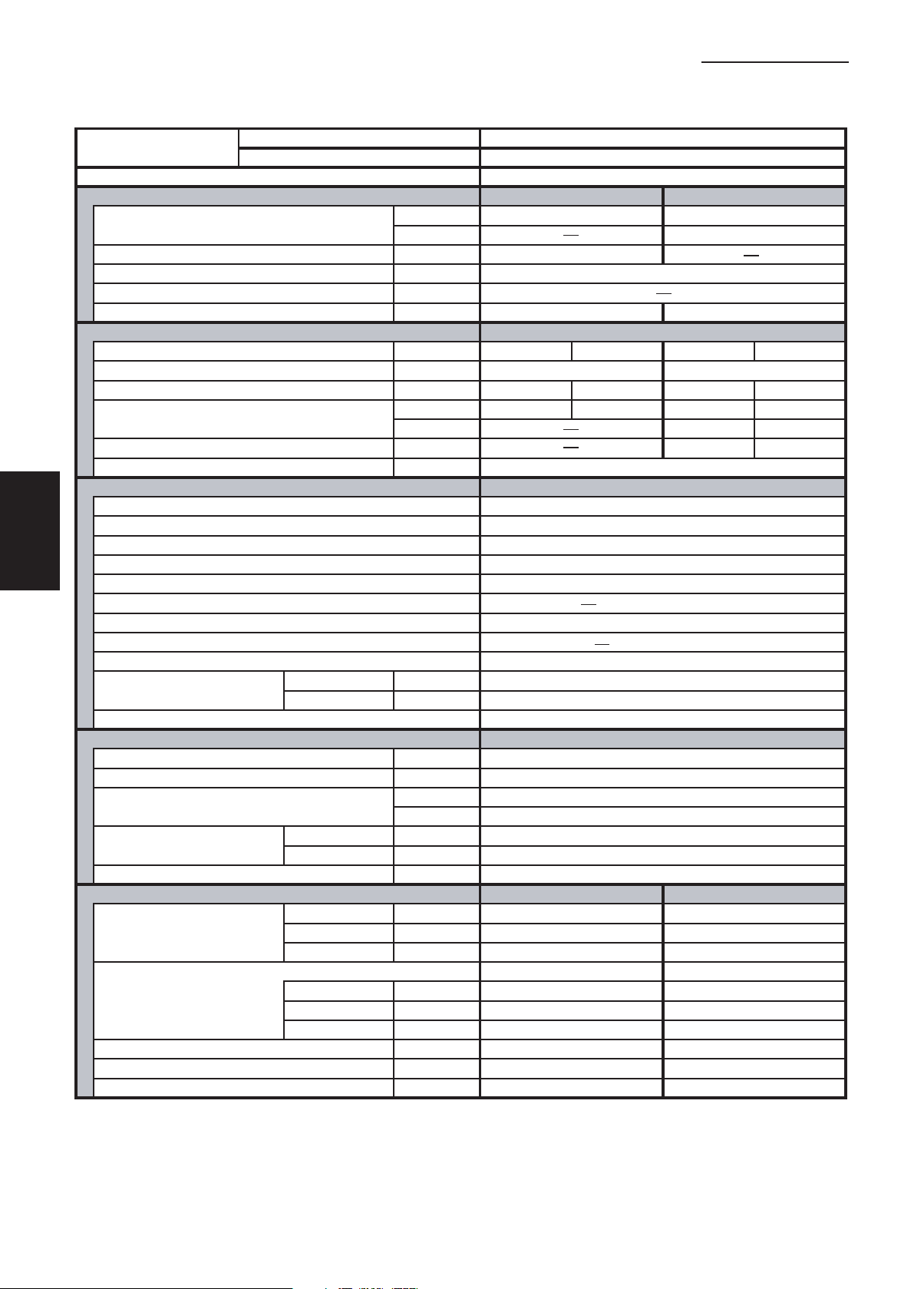
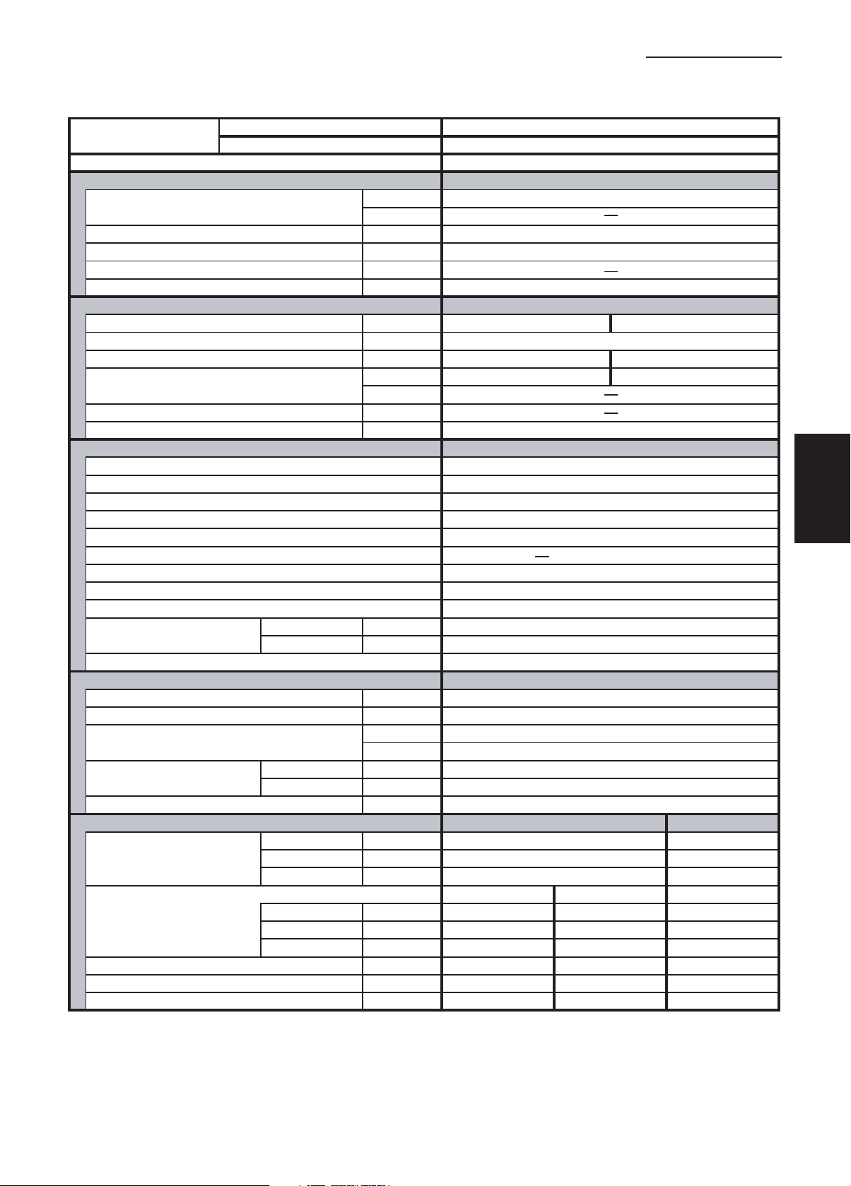
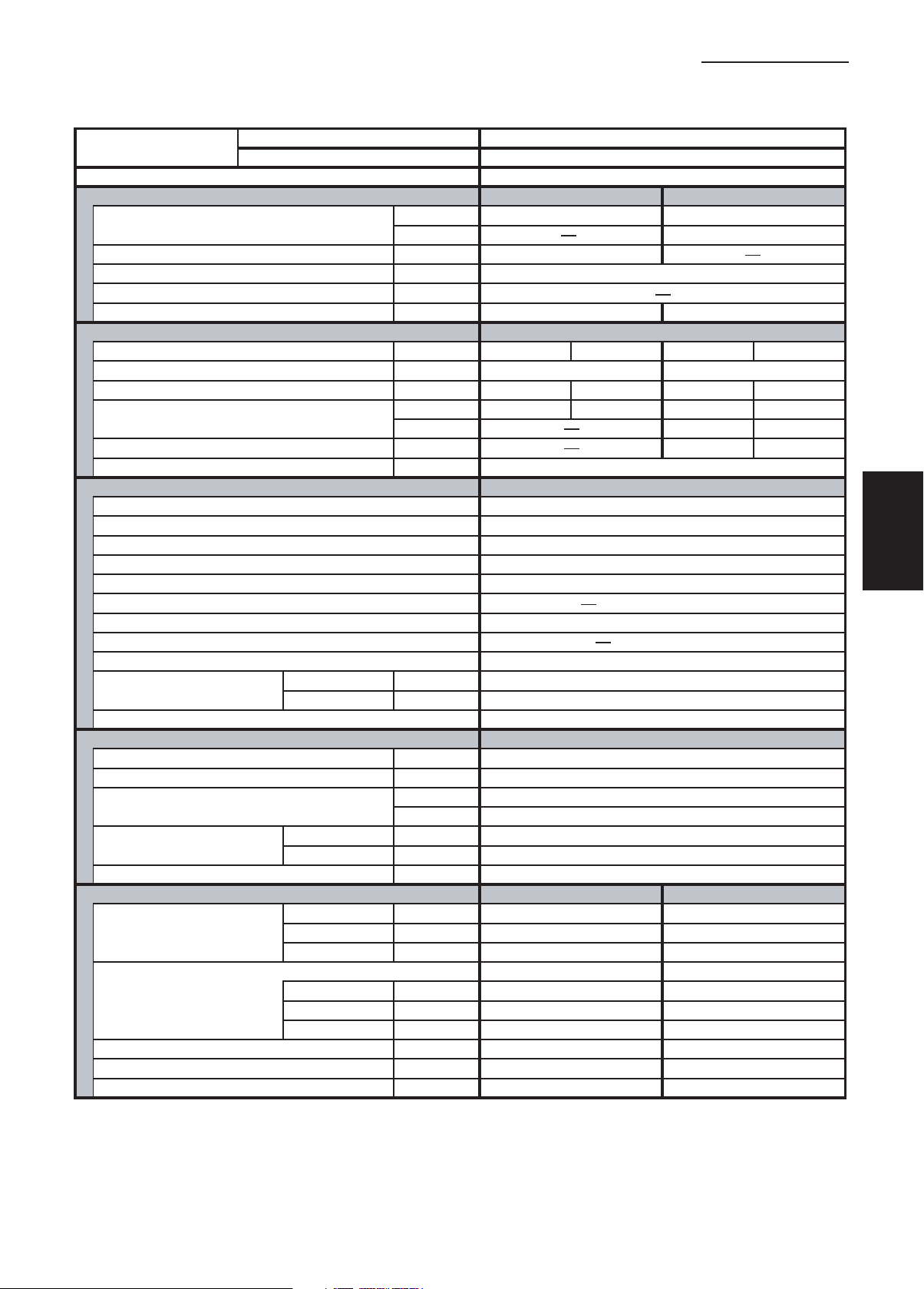
1-1 Unit Specifications
Wall-Mounted Type
1. Specifications
1
2
3
4
5
MODEL No.
POWER SOURCE
PERFORMANCE
Capacity * [minimum~muximum] BTU / h 23,000 [9,500~23,000] 27,600 [8,000~27,600]
Moisture removal (High) Pints / h 7.4
Air circulation (H / M / L) 230 V CFM 540 / 460 / 380
External Static Pressure
S.E.E.R. / H.S.P.F. (Region 4) BTU / Wh 15.9 10.3
ELECTRICAL RATINGS
Voltage rating V 230 208 230 208
Available voltage range V VAC 187 - 253 VAC 187 - 253
Max. Running amperes* (Without Back-up Heater)
Power input W 2,610 2,610 2,720 2,720
Back-up Heater kW 1.8 1.47
Maximum overcurrent protection (Indoor/Outdoor)
FEATURES
Controls
Low ambient control Built-in 0˚F
Fan speeds Indoor / Outdoor 3 and Automatic control / Variable
Optional Wired Remote Controller
Optional Wireless Remote Controller RCS-SH1UA / RCS-BH80UA. WL
Air deflection (Horizontal / Vertical )
Air filter Washable
Drain pump (Drain connection) (20A , OD26mm)
Compressor Rotary(SANYO)
Operation sound
Refrigerant control
REFRIGERANT TUBING
Limit of tubing length ft. (m) 165 (50)
Limit of tubing length at shipment ft. (m) 10~100 (3~30)
Limit of elevation difference ft. (m) Outdoor unit is higher than indoor unit : 100 (30)
between the two units ft. (m) Outdoor unit is lower than indoor unit : 50 (15)
Refrigerant tube Narrow tube in. (mm) 3 / 8 (6.35)
outer diameter Wide tube in. (mm) 5 / 8 (15.88)
Refrigerant amount at shipment lbs. (kg) 4.19 (1.9) - R410A
DIMENSIONS & WEIGHT
Unit dimensions Height in. (mm) 14- 9/16 (370) 30- 23/32 (780)
Package dimensions Indoor unit Outdoor unit
Net weight lbs. (kg) 44.1 (20) 128 (58)
Shipping weight lbs. (kg) 59.5 (27) 148 (67)
Shipping volume cu.ft. (m 3 ) 6.4 (0.181) 13.0 (0.369)
Cooling:
Rating conditions (*) : Room temperature 80 °F DB / 67 °F WB, Ambient temperature 95 °F DB / 75 °F WB
Indoor Unit KHH2672R
Outdoor Unit CH2672R
230 - 208 V / 1 Phase / 60 Hz
Cooling Heating
(17˚F)** BTU / h 18,500
in. WG
A 14.0 15.5 14.6 16.1
(17˚F)** W 2,160 2,160
A 15 / 30
Microprocessor
RCS-SH80UG / RCS-TM80BG
/ Automatic (Vertical )
Indoor - Hi/Me/Lo
Outdoor - Hi dB - A 49
Width in. (mm) 49- 7/32 (1,250) 37 (940)
Depth in. (mm) 8- 9/32 (210) 13- 3/8 (340)
Height in. (mm) 18- 7/16 (468) 34- 31/32 (888)
Width in. (mm) 52- 23/32 (1,339) 39- 31/32 (1,015)
Depth in. (mm) 11- 3/8 (289) 16- 3/32 (409)
dB - A 45 / 42 / 40
Electronic Expansion Valve (MOV)
Indoor unit Outdoor unit
DATA SUBJECT TO CHANGE WITHOUT NOTICE.
6
Heating:
Rating conditions (*) : Room temperature 70 °F DB / 60 °F WB, Ambient temperature 47 °F DB / 43 °F WB
Low temp conditions (**) : Room temperature 70 °F DB / 60 °F WB, Ambient temperature 17 °F DB / 15 °F WB
SM831148
I-2
Page 7

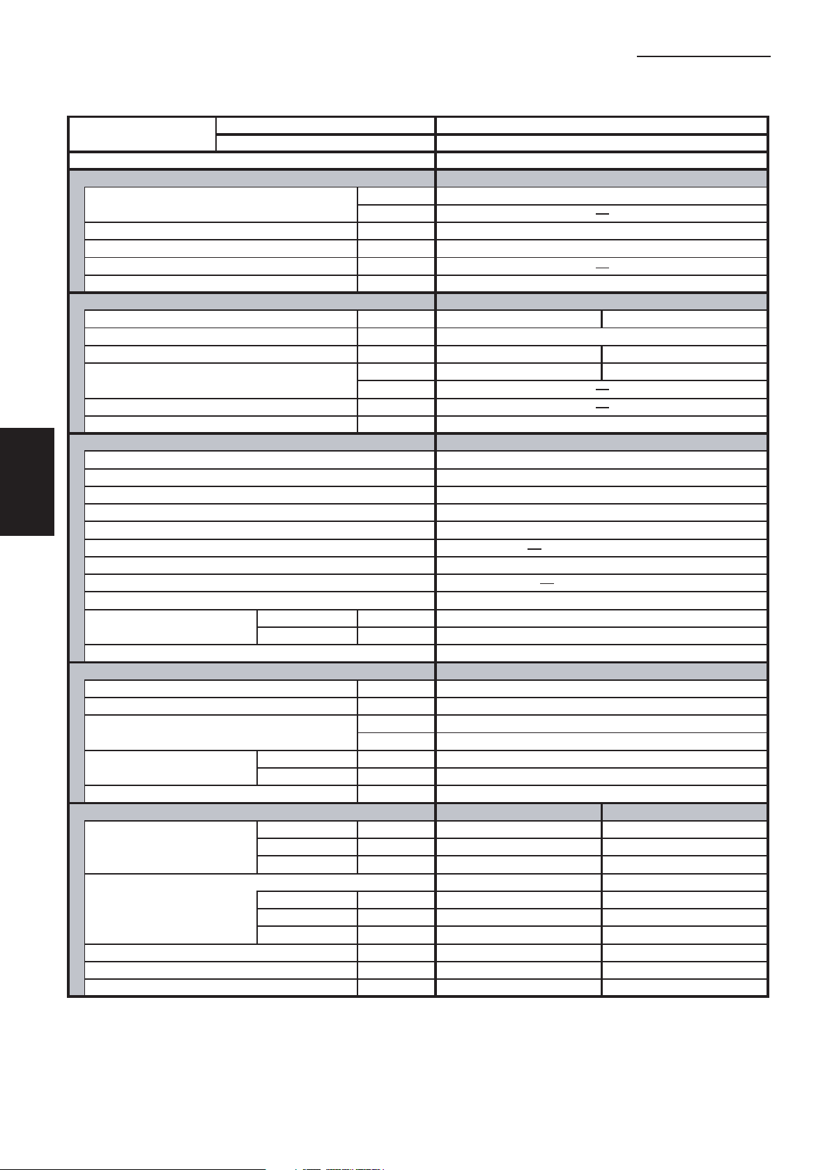
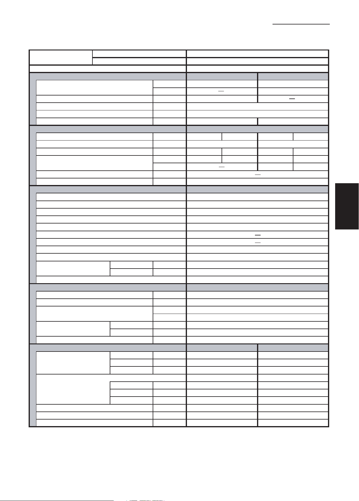
1-1 Unit Specifications
Wall-Mounted Type
1. Specifications
MODEL No.
POWER SOURCE
PERFORMANCE
Capacity * [minimum~muximum] BTU / h 25,200 [9,500~25,200] 29,200 [8,000~29,200]
Moisture removal (High) Pints / h 8.1
Air circulation (H / M / L) 230 V CFM 559 / 475 / 390
External Static Pressure
S.E.E.R. / H.S.P.F. (Region 4) BTU / Wh 14.9 10.2
ELECTRICAL RATINGS
Voltage rating V 230 208 230 208
Available voltage range V VAC 187 - 253 VAC 187 - 253
Max. Running amperes*
Power input W 2,840 2,840 2,620 2,620
Back-up Heater kW
Maximum overcurrent protection (Indoor/Outdoor)
FEATURES
Controls Microprocessor
Low ambient control Built-in 0˚F
Fan speeds Indoor / Outdoor 3 and Automatic control / Variable
Optional Wired Remote Controller
Optional Wireless Remote Controller RCS-SH1UA / RCS-BH80UA. WL
Air deflection (Horizontal / Vertical )
Air filter Washable
Drain pump (Drain connection) (20A , OD26mm)
Compressor Rotary(SANYO)
Operation sound
Refrigerant control
REFRIGERANT TUBING
Limit of tubing length ft. (m) 165 (50)
Limit of tubing length at shipment ft. (m) 10~100 (3~30)
Limit of elevation difference ft. (m) Outdoor unit is higher than indoor unit : 100 (30)
between the two units ft. (m) Outdoor unit is lower than indoor unit : 50 (15)
Refrigerant tube Narrow tube in. (mm) 3 / 8 (6.35)
outer diameter Wide tube in. (mm) 5 / 8 (15.88)
Refrigerant amount at shipment lbs. (kg) 4.19 (1.9) - R410A
DIMENSIONS & WEIGHT
Unit dimensions Height in. (mm) 12- 63/64 (330) 30- 23/32 (780)
Package dimensions Indoor unit Outdoor unit
Net weight lbs. (kg) 40 (18) 128 (58)
Shipping weight lbs. (kg) 44 (20) 148 (67)
Shipping volume cu.ft. (m 3 ) 4.9 (0.139) 13.0 (0.369)
Cooling:
Rating conditions (*) : Room temperature 80 °F DB / 67 °F WB, Ambient temperature 95 °F DB / 75 °F WB
Indoor Unit KH2672R
Outdoor Unit CH2672R
230 - 208 V / 1 Phase / 60 Hz
Cooling Heating
(17˚F)** BTU / h 17,200
in. WG
A 15.3 16.9 14.0 15.5
(17˚F)** W 2,030 2,030
A 15 / 30
RCS-SH80UG / RCS-TM80BG
/ Automatic (Vertical )
Indoor - Hi/Me/Lo
Outdoor - Hi dB - A 49
Width in. (mm) 44- 7/8 (1,140) 37 (940)
Depth in. (mm) 8- 31/32 (228) 13- 3/8 (340)
Height in. (mm) 15- 11/32 (390) 34- 31/32 (888)
Width in. (mm) 47- 27/32 (1,215) 39- 31/32 (1,015)
Depth in. (mm) 11- 17/32 (293) 16- 3/32 (409)
dB - A 48 / 42 / 38
Electronic Expansion Valve (MOV)
Indoor unit Outdoor unit
DATA SUBJECT TO CHANGE WITHOUT NOTICE.
1
2
3
4
5
Heating:
Rating conditions (*) : Room temperature 70 °F DB / 60 °F WB, Ambient temperature 47 °F DB / 43 °F WB
Low temp conditions (**) : Room temperature 70 °F DB / 60 °F WB, Ambient temperature 17 °F DB / 15 °F WB
I-3
6
SM831148
Page 8

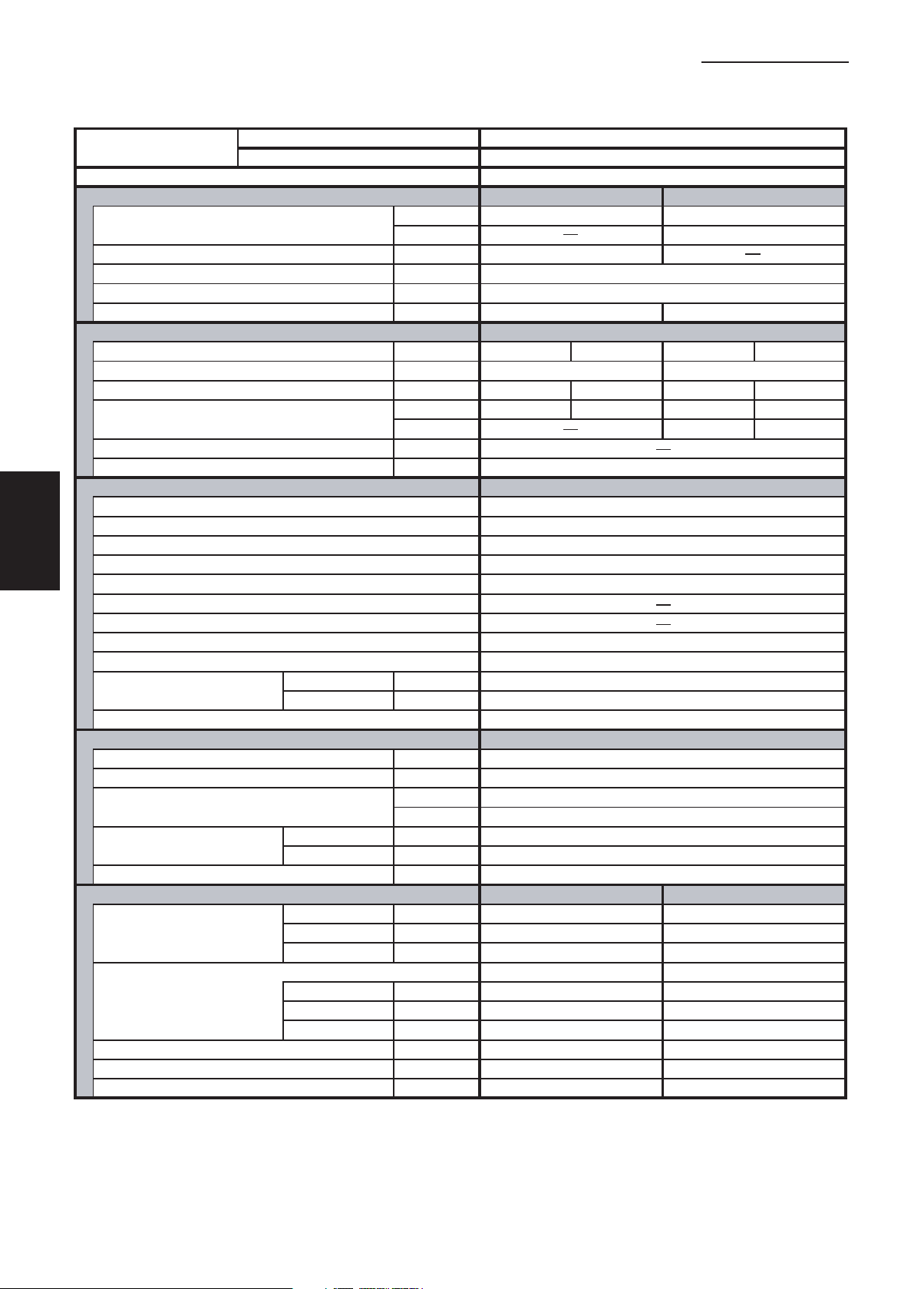
1-1 Unit Specifications
Wall-Mounted Type
1. Specifications
1
2
3
4
5
MODEL No.
POWER SOURCE
PERFORMANCE
Capacity * [minimum~muximum] BTU / h 29,800 [9,500~29,800] 34,800 [8,000~34,800]
Moisture removal (High) Pints / h 9.7
Air circulation (H / M / L) 230 V CFM 840 / 740 / 620
External Static Pressure
S.E.E.R. / H.S.P.F. (Region 4) BTU / Wh 15.0 9.0
ELECTRICAL RATINGS
Voltage rating V 230 208 230 208
Available voltage range V VAC 187 - 253 VAC 187 - 253
Max. Running amperes* A 17.7 19.6 16.2 17.9
Power input W 3,690 3,690 3,390 3,390
Back-up Heater kW
Maximum overcurrent protection (Indoor/Outdoor)
FEATURES
Controls Microprocessor
Low ambient control Built-in 0˚F
Fan speeds Indoor / Outdoor 3 and Automatic control / Variable
Optional Wired Remote Controller
Optional Wireless Remote Controller RCS-SH1UA / RCS-BH80UA. WL
Air deflection (Horizontal / Vertical )
Air filter Washable
Drain pump (Drain connection) (20A , OD26mm)
Compressor Rotary(SANYO)
Operation sound
Refrigerant control Electronic Expansion Valve (MOV)
REFRIGERANT TUBING
Limit of tubing length ft. (m) 165 (50)
Limit of tubing length at shipment ft. (m) 10~100 (3~30)
Limit of elevation difference ft. (m) Outdoor unit is higher than indoor unit : 100 (30)
between the two units ft. (m) Outdoor unit is lower than indoor unit : 50 (15)
Refrigerant tube Narrow tube in. (mm) 3 / 8 (6.35)
outer diameter Wide tube in. (mm) 5 / 8 (15.88)
Refrigerant amount at shipment lbs. (kg) 5.73 (2.6) - R410A
DIMENSIONS & WEIGHT
Unit dimensions Height in. (mm) 14- 9/16 (370) 30- 23/32 (780)
Package dimensions Indoor unit Outdoor unit
Net weight lbs. (kg) 63.9 (29) 143 (65)
Shipping weight lbs. (kg) 81.6 (37) 161 (73)
Shipping volume cu.ft. (m 3 ) 8.4 (0.237) 13.0 (0.369)
Cooling:
Rating conditions (*) : Room temperature 80 °F DB / 67 °F WB, Ambient temperature 95 °F DB / 75 °F WB
Indoor Unit KH3072R
Outdoor Unit CH3072R
230 - 208 V / 1 Phase / 60 Hz
Cooling Heating
(17˚F)** BTU / h 20,000
in. WG
(17˚F)** W 2,460 2,460
A 15 / 35
RCS-SH80UG / RCS-TM80BG
/ Automatic (Vertical )
Indoor - Hi/Me/Lo
Outdoor - Hi dB - A 52
Width in. (mm) 59- 1/16 (1,500) 37 (940)
Depth in. (mm) 9- 7/16 (240) 13- 3/8 (340)
Height in. (mm) 18- 7/16 (468) 34- 31/32 (888)
Width in. (mm) 62- 9/16 (1,589) 39- 31/32 (1,015)
Depth in. (mm) 12- 9/16 (319) 16- 3/32 (409)
dB - A 46 / 42 / 38
Indoor unit Outdoor unit
DATA SUBJECT TO CHANGE WITHOUT NOTICE.
6
Heating:
Rating conditions (*) : Room temperature 70 °F DB / 60 °F WB, Ambient temperature 47 °F DB / 43 °F WB
Low temp conditions (**) : Room temperature 70 °F DB / 60 °F WB, Ambient temperature 17 °F DB / 15 °F WB
SM831148
I-4
Page 9

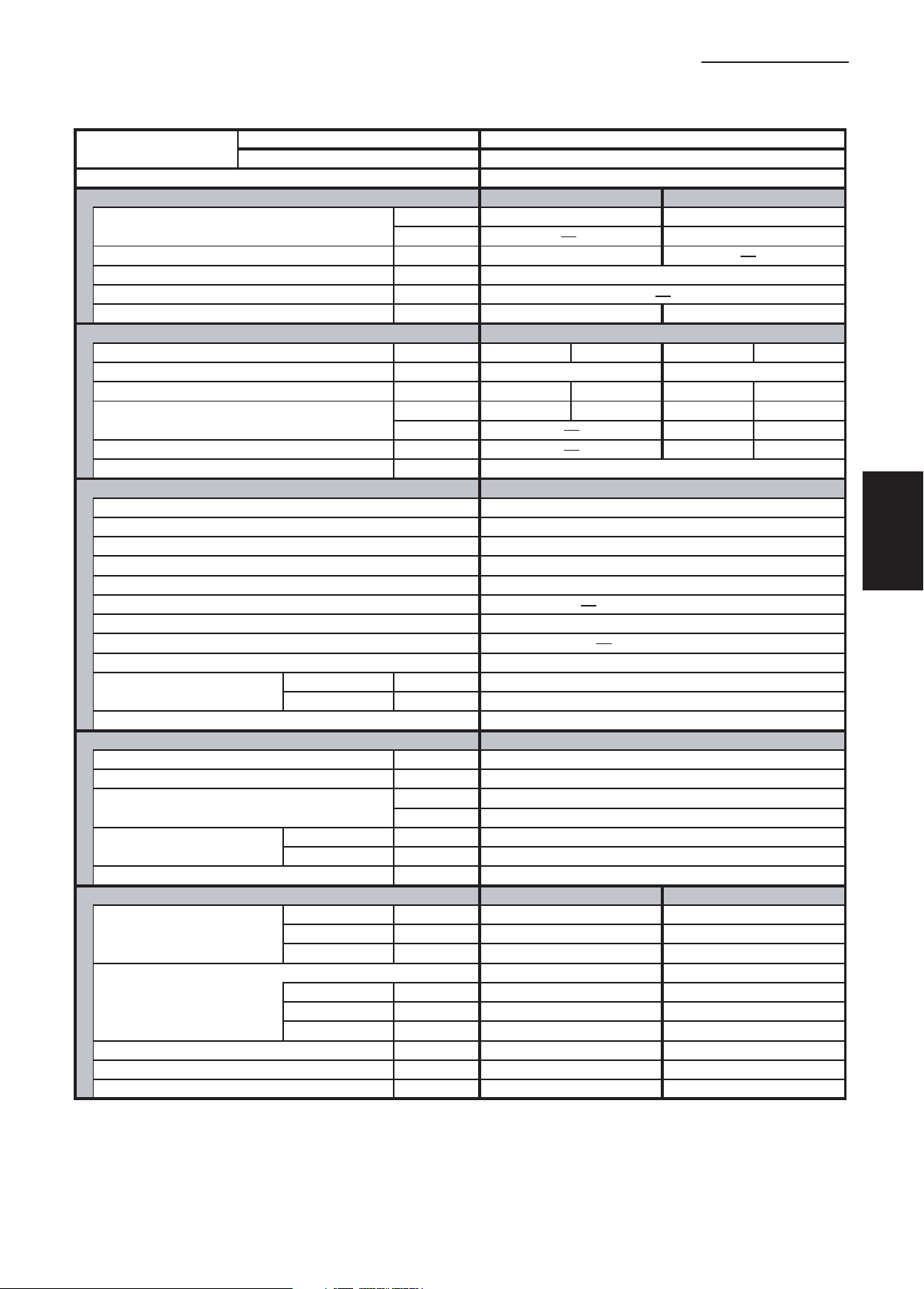
1-1 Unit Specifications
Wall-Mounted Type
1. Specifications
MODEL No.
POWER SOURCE
PERFORMANCE
Capacity * [minimum~muximum] BTU / h 31,400 [9,500~31,400] 36,400 [8,000~36,400]
Moisture removal (High) Pints / h 10.0
Air circulation (H / M / L) 230 V CFM 830 / 710 / 590
External Static Pressure
S.E.E.R. / H.S.P.F. (Region 4) BTU / Wh 15.9 9.0
ELECTRICAL RATINGS
Voltage rating V 230 208 230 208
Available voltage range V VAC 187 - 253 VAC 187 - 253
Max. Running amperes* A 17.9 19.8 15.9 17.6
Power input W 3,750 3,750 3,320 3,320
Back-up Heater kW
Maximum overcurrent protection (Indoor/Outdoor)
FEATURES
Controls Microprocessor
Low ambient control Built-in 0˚F
Fan speeds Indoor / Outdoor 3 and Automatic control / Variable
Optional Wired Remote Controller
Optional Wireless Remote Controller RCS-SH1UA / RCS-BH80UA. WL
Air deflection (Horizontal / Vertical )
Air filter Washable
Drain pump (Drain connection) (20A , OD26mm)
Compressor Rotary(SANYO)
Operation sound
Refrigerant control Electronic Expansion Valve (MOV)
REFRIGERANT TUBING
Limit of tubing length ft. (m) 165 (50)
Limit of tubing length at shipment ft. (m) 10~100 (3~30)
Limit of elevation difference ft. (m) Outdoor unit is higher than indoor unit : 100 (30)
between the two units ft. (m) Outdoor unit is lower than indoor unit : 50 (15)
Refrigerant tube Narrow tube in. (mm) 3 / 8 (6.35)
outer diameter Wide tube in. (mm) 5 / 8 (15.88)
Refrigerant amount at shipment lbs. (kg) 6.17 (2.8) - R410A
DIMENSIONS & WEIGHT
Unit dimensions Height in. (mm) 14- 9/16 (370) 30- 23/32 (780)
Package dimensions Indoor unit Outdoor unit
Net weight lbs. (kg) 72.8 (33) 143 (65)
Shipping weight lbs. (kg) 90.4 (41) 161 (73)
Shipping volume cu.ft. (m 3 ) 8.4 (0.237) 13.0 (0.369)
Cooling:
Rating conditions (*) : Room temperature 80 °F DB / 67 °F WB, Ambient temperature 95 °F DB / 75 °F WB
Indoor Unit KH3672R
Outdoor Unit CH3672R
230 - 208 V / 1 Phase / 60 Hz
Cooling Heating
(17˚F)** BTU / h 20,200
in. WG
(17˚F)** W 2,450 2,450
A 15 / 35
RCS-SH80UG / RCS-TM80BG
/ Automatic (Vertical )
Indoor - Hi/Me/Lo
Outdoor - Hi dB - A 52
Width in. (mm) 59- 1/16 (1,500) 37 (940)
Depth in. (mm) 9- 7/16 (240) 13- 3/8 (340)
Height in. (mm) 18- 7/16 (468) 34- 31/32 (888)
Width in. (mm) 62- 9/16 (1,589) 39- 31/32 (1,015)
Depth in. (mm) 12- 9/16 (319) 16- 3/32 (409)
dB - A 48 / 44 / 40
Indoor unit Outdoor unit
DATA SUBJECT TO CHANGE WITHOUT NOTICE.
1
2
3
4
5
Heating:
Rating conditions (*) : Room temperature 70 °F DB / 60 °F WB, Ambient temperature 47 °F DB / 43 °F WB
Low temp conditions (**) : Room temperature 70 °F DB / 60 °F WB, Ambient temperature 17 °F DB / 15 °F WB
I-5
6
SM831148
Page 10
1-1 Unit Specifications
Wall-Mounted Type
1. Specifications
1
2
3
4
5
MODEL No.
POWER SOURCE
PERFORMANCE
Capacity * [minimum~muximum] BTU / h 25,200 [9,500~25,200]
Moisture removal (High) Pints / h 8.1
Air circulation (H / M / L) 230 V CFM 559 / 475 / 390
External Static Pressure
S.E.E.R. / H.S.P.F. (Region 4) BTU / Wh 14.9
ELECTRICAL RATINGS
Voltage rating V 230 208
Available voltage range V VAC 187 - 253
Max. Running amperes*
Power input W 2,840 2,840
Back-up Heater kW
Maximum overcurrent protection (Indoor/Outdoor)
FEATURES
Controls Microprocessor
Low ambient control Built-in 0˚F
Fan speeds Indoor / Outdoor 3 and Automatic control / Variable
Optional Wired Remote Controller
Optional Wireless Remote Controller RCS-SH1UA / RCS-BH80UA. WL
Air deflection (Horizontal / Vertical )
Air filter Washable
Drain pump (Drain connection)
Compressor Rotary(SANYO)
Operation sound
Refrigerant control Electronic Expansion Valve (MOV)
REFRIGERANT TUBING
Limit of tubing length ft. (m) 165 (50)
Limit of tubing length at shipment ft. (m) 10~100 (3~30)
Limit of elevation difference ft. (m) Outdoor unit is higher than indoor unit : 100 (30)
between the two units ft. (m) Outdoor unit is lower than indoor unit : 50 (15)
Refrigerant tube Narrow tube in. (mm) 3 / 8 (6.35)
outer diameter Wide tube in. (mm) 5 / 8 (15.88)
Refrigerant amount at shipment lbs. (kg) 4.19 (1.9) - R410A
DIMENSIONS & WEIGHT
Unit dimensions Height in. (mm) 12- 63/64 (330) 30- 23/32 (780)
Package dimensions Indoor unit Outdoor unit
Net weight lbs. (kg) 40 (18) 128 (58)
Shipping weight lbs. (kg) 44 (20) 148 (67)
Shipping volume cu.ft. (m 3 ) 4.9 (0.139) 13.0 (0.369)
Cooling:
Rating conditions (*) : Room temperature 80 °F DB / 67 °F WB, Ambient temperature 95 °F DB / 75 °F WB
Indoor Unit KH2672R
Outdoor Unit C2672R
230 - 208 V / 1 Phase / 60 Hz
Cooling
(17˚F)** BTU / h
in. WG
A 15.3 16.9
(17˚F)** W
A 15 / 30
RCS-SH80UG / RCS-TM80BG
/ Automatic (Vertical )
(20A , OD26mm)
Indoor - Hi/Me/Lo
Outdoor - Hi dB - A 49
Width in. (mm) 44- 7/8 (1,140) 37 (940)
Depth in. (mm) 8- 31/32 (228) 13- 3/8 (340)
Height in. (mm) 15- 11/32 (390) 34- 31/32 (888)
Width in. (mm) 47- 27/32 (1,215) 39- 31/32 (1,015)
Depth in. (mm) 11- 17/32 (293) 16- 3/32 (409)
dB - A 48 / 42 / 38
Indoor unit Outdoor unit
DATA SUBJECT TO CHANGE WITHOUT NOTICE.
6
Heating:
Rating conditions (*) : Room temperature 70 °F DB / 60 °F WB, Ambient temperature 47 °F DB / 43 °F WB
Low temp conditions (**) : Room temperature 70 °F DB / 60 °F WB, Ambient temperature 17 °F DB / 15 °F WB
SM831148
I-6
Page 11

1-1 Unit Specifications
Wall-Mounted Type
1. Specifications
MODEL No.
POWER SOURCE
PERFORMANCE
Capacity * [minimum~muximum] BTU / h 29,800 [9,500~29,800]
Moisture removal (High) Pints / h 9.7
Air circulation (H / M / L) 230 V CFM 840 / 740 / 620
External Static Pressure
S.E.E.R. BTU / Wh 15.0
ELECTRICAL RATINGS
Voltage rating V 230 208
Available voltage range V VAC 187 - 253
Max. Running amperes* A 17.7 19.6
Power input W 3,690 3,690
Back-up Heater kW
Maximum overcurrent protection (Indoor/Outdoor)
FEATURES
Controls Microprocessor
Low ambient control Built-in 0˚F
Fan speeds Indoor / Outdoor 3 and Automatic control / Variable
Optional Wired Remote Controller
Optional Wireless Remote Controller RCS-SH1UA / RCS-BH80UA. WL
Air deflection (Horizontal / Vertical )
Air filter Washable
Drain pump (Drain connection) (20A , OD26mm)
Compressor Rotary(SANYO)
Operation sound
Refrigerant control Electronic Expansion Valve (MOV)
REFRIGERANT TUBING
Limit of tubing length ft. (m) 165 (50)
Limit of tubing length at shipment ft. (m) 10~100 (3~30)
Limit of elevation difference ft. (m) Outdoor unit is higher than indoor unit : 100 (30)
between the two units ft. (m) Outdoor unit is lower than indoor unit : 50 (15)
Refrigerant tube Narrow tube in. (mm) 3 / 8 (6.35)
outer diameter Wide tube in. (mm) 5 / 8 (15.88)
Refrigerant amount at shipment lbs. (kg) 5.73 (2.6) - R410A
DIMENSIONS & WEIGHT
Unit dimensions Height in. (mm) 14- 9/16 (370) 30- 23/32 (780)
Package dimensions Indoor unit Outdoor unit
Net weight lbs. (kg) 63.9 (29) 143 (65)
Shipping weight lbs. (kg) 81.6 (37) 161 (73)
Shipping volume cu.ft. (m 3 ) 8.4 (0.237) 13.0 (0.369)
Cooling:
Rating conditions (*) : Room temperature 80 °F DB / 67 °F WB, Ambient temperature 95 °F DB / 75 °F WB
Indoor Unit KH3072R
Outdoor Unit C3072R
230 - 208 V / 1 Phase / 60 Hz
Cooling
(17˚F)** BTU / h
in. WG
(17˚F)** W
A 15 / 35
RCS-SH80UG / RCS-TM80BG
/ Automatic (Vertical )
Indoor - Hi/Me/Lo
Outdoor - Hi dB - A 52
Width in. (mm) 59- 1/16 (1,500) 37 (940)
Depth in. (mm) 9- 7/16 (240) 13- 3/8 (340)
Height in. (mm) 18- 7/16 (468) 34- 31/32 (888)
Width in. (mm) 62- 9/16 (1,589) 39- 31/32 (1,015)
Depth in. (mm) 12- 9/16 (319) 16- 3/32 (409)
dB - A 46 / 42 / 38
Indoor unit Outdoor unit
DATA SUBJECT TO CHANGE WITHOUT NOTICE.
1
2
3
4
5
Heating:
Rating conditions (*) : Room temperature 70 °F DB / 60 °F WB, Ambient temperature 47 °F DB / 43 °F WB
Low temp conditions (**) : Room temperature 70 °F DB / 60 °F WB, Ambient temperature 17 °F DB / 15 °F WB
I-7
6
SM831148
Page 12

1-1 Unit Specifications
Wall-Mounted Type
1. Specifications
1
2
3
4
5
MODEL No.
POWER SOURCE
PERFORMANCE
Capacity * [minimum~muximum] BTU / h 31,400 [9,500~31,400]
Moisture removal (High) Pints / h 10.0
Air circulation (H / M / L) 230 V CFM 830 / 710 / 590
External Static Pressure
S.E.E.R. BTU / Wh 15.9
ELECTRICAL RATINGS
Voltage rating V 230 208
Available voltage range V VAC 187 - 253
Max. Running amperes* A 17.9 19.8
Power input W 3,750 3,750
Back-up Heater kW
Maximum overcurrent protection (Indoor/Outdoor)
FEATURES
Controls Microprocessor
Low ambient control Built-in 0˚F
Fan speeds Indoor / Outdoor 3 and Automatic control / Variable
Optional Wired Remote Controller
Optional Wireless Remote Controller RCS-SH1UA / RCS-BH80UA. WL
Air deflection (Horizontal / Vertical )
Air filter Washable
Drain pump (Drain connection) (20A , OD26mm)
Compressor Rotary(SANYO)
Operation sound
Refrigerant control Electronic Expansion Valve (MOV)
REFRIGERANT TUBING
Limit of tubing length ft. (m) 165 (50)
Limit of tubing length at shipment ft. (m) 10~100 (3~30)
Limit of elevation difference ft. (m) Outdoor unit is higher than indoor unit : 100 (30)
between the two units ft. (m) Outdoor unit is lower than indoor unit : 50 (15)
Refrigerant tube Narrow tube in. (mm) 3 / 8 (6.35)
outer diameter Wide tube in. (mm) 5 / 8 (15.88)
Refrigerant amount at shipment lbs. (kg) 6.17 (2.8) - R410A
DIMENSIONS & WEIGHT
Unit dimensions Height in. (mm) 14- 9/16 (370) 30- 23/32 (780)
Package dimensions Indoor unit Outdoor unit
Net weight lbs. (kg) 72.8 (33) 143 (65)
Shipping weight lbs. (kg) 90.4 (41) 161 (73)
Shipping volume cu.ft. (m 3 ) 8.4 (0.237) 13.0 (0.369)
Cooling:
Rating conditions (*) : Room temperature 80 °F DB / 67 °F WB, Ambient temperature 95 °F DB / 75 °F WB
Indoor Unit KH3672R
Outdoor Unit C3672R
230 - 208 V / 1 Phase / 60 Hz
Cooling
(17˚F)** BTU / h
in. WG
(17˚F)** W
A 15 / 35
RCS-SH80UG / RCS-TM80BG
/ Automatic (Vertical )
Indoor - Hi/Me/Lo
Outdoor - Hi dB - A 52
Width in. (mm) 59- 1/16 (1,500) 37 (940)
Depth in. (mm) 9- 7/16 (240) 13- 3/8 (340)
Height in. (mm) 18- 7/16 (468) 34- 31/32 (888)
Width in. (mm) 62- 9/16 (1,589) 39- 31/32 (1,015)
Depth in. (mm) 12- 9/16 (319) 16- 3/32 (409)
dB - A 48 / 44 / 40
Indoor unit Outdoor unit
DATA SUBJECT TO CHANGE WITHOUT NOTICE.
6
Heating:
Rating conditions (*) : Room temperature 70 °F DB / 60 °F WB, Ambient temperature 47 °F DB / 43 °F WB
Low temp conditions (**) : Room temperature 70 °F DB / 60 °F WB, Ambient temperature 17 °F DB / 15 °F WB
SM831148
I-8
Page 13

1-1 Unit Specifications
4-Way Air Discharge Semi-Concealed Type
1. Specifications
MODEL No.
POWER SOURCE
PERFORMANCE
Capacity * [minimum~muximum] BTU / h 24,800 [9,500~24,800] 29,800 [8,000~29,800]
Moisture removal (High) Pints / h 8.1
Air circulation (H / M / L) 230 V CFM 710 / 530 / 450
External Static Pressure
S.E.E.R. / H.S.P.F. (Region 4) BTU / Wh 14.1 10.5
ELECTRICAL RATINGS
Voltage rating V 230 208 230 208
Available voltage range V VAC 187 - 253 VAC 187 - 253
Max. Running amperes*
Power input W 2,920 2,920 2,790 2,790
Back-up Heater kW
Maximum overcurrent protection (Indoor/Outdoor)
FEATURES
Controls Microprocessor
Low ambient control Built-in 0˚F
Fan speeds Indoor / Outdoor 3 and Automatic control / Variable
Optional Wired Remote Controller
Optional Wireless Remote Controller
Air deflection (Horizontal / Vertical ) / Automatic (Vertical )
Air filter Washable, long life (2,500 hr)
Drain pump (Drain connection)
Compressor Rotary(SANYO)
Operation sound
Refrigerant control Electronic Expansion Valve (MOV)
REFRIGERANT TUBING
Limit of tubing length ft. (m) 165 (50)
Limit of tubing length at shipment ft. (m) 10~100 (3~30)
Limit of elevation difference ft. (m) Outdoor unit is higher than indoor unit : 100 (30)
between the two units ft. (m) Outdoor unit is lower than indoor unit : 50 (15)
Refrigerant tube Narrow tube in. (mm) 3 / 8 (6.35)
outer diameter Wide tube in. (mm) 5 / 8 (15.88)
Refrigerant amount at shipment lbs. (kg) 4.19 (1.9) - R410A
DIMENSIONS & WEIGHT
Unit dimensions Height in. (mm) 13-5/16 (338) 30- 23/32 (780)
Package dimensions Body Panel Outdoor unit
Net weight lbs. (kg) 49 (22) 11 (5) 128 (58)
Shipping weight lbs. (kg) 57 (26) 18 (8) 148 (67)
Shipping volume cu.ft. (m 3 ) 7.1 (0.200) 3.6 (0.100) 13.0 (0.369)
Cooling:
Rating conditions (*) : Room temperature 80 °F DB / 67 °F WB, Ambient temperature 95 °F DB / 75 °F WB
Indoor Unit XH2672R
Outdoor Unit CH2672R
230 - 208 V / 1 Phase / 60 Hz
Cooling Heating
(17˚F)** BTU / h 18,300
in. WG
A 15.6 17.3 14.8 16.4
(17˚F)** W 2,200 2,200
A 15 / 30
RCS-SH80UG / RCS-TM80BG
RCS-SH80UA.WL / RCS-BH80UA. WL
Max.head 2-33/64 in. above drain connection (25A , OD32mm)
Indoor - Hi/Me/Lo
Outdoor - Hi dB - A 49
Width in. (mm) 33-55/64 (860) 37 (940)
Depth in. (mm) 33-55/64 (860) 13- 3/8 (340)
Height in. (mm) 11-9/64 (283) 4-3/32 (104) 34- 31/32 (888)
Width in. (mm) 32-7/8 (835) 37-61/64 (964) 39- 31/32 (1,015)
Depth in. (mm) 33-9/32 (845) 39-21/64 (999) 16- 3/32 (409)
dB - A 38 / 35 / 31
Indoor unit (Include panel) Outdoor unit
DATA SUBJECT TO CHANGE WITHOUT NOTICE.
1
2
3
4
5
Heating:
Rating conditions (*) : Room temperature 70 °F DB / 60 °F WB, Ambient temperature 47 °F DB / 43 °F WB
Low temp conditions (**) : Room temperature 70 °F DB / 60 °F WB, Ambient temperature 17 °F DB / 15 °F WB
I-9
6
SM831148
Page 14

1-1 Unit Specifications
4-Way Air Discharge Semi-Concealed Type
1. Specifications
1
2
3
4
5
MODEL No.
POWER SOURCE
PERFORMANCE
Capacity * [minimum~muximum] BTU / h 32,600 [9,500~32,600] 37,600 [8,000~37,600]
Moisture removal (High) Pints / h 10.6
Air circulation (H / M / L) 230 V CFM 1050 / 840 / 720
External Static Pressure
S.E.E.R. / H.S.P.F. (Region 4) BTU / Wh 14.6 9.1
ELECTRICAL RATINGS
Voltage rating V 230 208 230 208
Available voltage range V VAC 187 - 253 VAC 187 - 253
Max. Running amperes* A 18.7 20.7 15.9 17.6
Power input W 3,950 3,950 3,350 3,350
Back-up Heater kW
Maximum overcurrent protection (Indoor/Outdoor)
FEATURES
Controls Microprocessor
Low ambient control Built-in 0˚F
Fan speeds Indoor / Outdoor 3 and Automatic control / Variable
Optional Wired Remote Controller
Optional Wireless Remote Controller RCS-SH80UA. WL / RCS-BH80UA. WL
Air deflection (Horizontal / Vertical )
Air filter Washable, long life (2,500 hr)
Drain pump (Drain connection)
Compressor Rotary(SANYO)
Operation sound
Refrigerant control Electronic Expansion Valve (MOV)
REFRIGERANT TUBING
Limit of tubing length ft. (m) 165 (50)
Limit of tubing length at shipment ft. (m) 10~100 (3~30)
Limit of elevation difference ft. (m) Outdoor unit is higher than indoor unit : 100 (30)
between the two units ft. (m) Outdoor unit is lower than indoor unit : 50 (15)
Refrigerant tube Narrow tube in. (mm) 3 / 8 (6.35)
outer diameter Wide tube in. (mm) 5 / 8 (15.88)
Refrigerant amount at shipment lbs. (kg) 6.17 (2.8) - R410A
DIMENSIONS & WEIGHT
Unit dimensions Height in. (mm) 14-31/64 (368) 30- 23/32 (780)
Package dimensions Body Panel Outdoor unit
Net weight lbs. (kg) 60 (27) 16 (7) 143 (65)
Shipping weight lbs. (kg) 71 (32) 22 (10) 161 (73)
Shipping volume cu.ft. (m 3 ) 10.6 (0.299) 4.6 (0.131) 13.0 (0.369)
Cooling:
Rating conditions (*) : Room temperature 80 °F DB / 67 °F WB, Ambient temperature 95 °F DB / 75 °F WB
Indoor Unit XH3672R
Outdoor Unit CH3672R
230 - 208 V / 1 Phase / 60 Hz
Cooling Heating
(17˚F)** BTU / h 20,000
in. WG
(17˚F)** W 2,450 2,450
A 15 / 35
RCS-SH80UG / RCS-TM80BG
/ Automatic (Vertical )
Max.head 2-33/64 in. above drain connection (25A , OD32mm)
Indoor - Hi/Me/Lo
Outdoor - Hi dB - A 52
Width in. (mm) 45-9/32 (1,150) 37 (940)
Depth in. (mm) 33-55/64 (860) 13- 3/8 (340)
Height in. (mm) 12-13/32 (315) 4-3/32 (104) 34- 31/32 (888)
Width in. (mm) 44-19/64 (1,125) 49-31/64 (1,257) 39- 31/32 (1,015)
Depth in. (mm) 33-9/32 (845) 39-21/64 (999) 16- 3/32 (409)
dB - A 44 / 37 / 33
Indoor unit (Include panel) Outdoor unit
DATA SUBJECT TO CHANGE WITHOUT NOTICE.
6
Heating:
Rating conditions (*) : Room temperature 70 °F DB / 60 °F WB, Ambient temperature 47 °F DB / 43 °F WB
Low temp conditions (**) : Room temperature 70 °F DB / 60 °F WB, Ambient temperature 17 °F DB / 15 °F WB
SM831148
I-10
Page 15

1-1 Unit Specifications
4-Way Air Discharge Semi-Concealed Type
1. Specifications
MODEL No.
POWER SOURCE
PERFORMANCE
Capacity * [minimum~muximum] BTU / h 39,500 [9,500~39,500] 48,000 [8,000~48,000]
Moisture removal (High) Pints / h 12.6
Air circulation (H / M / L) 230 V CFM 1050 / 840 / 720
External Static Pressure
S.E.E.R. / H.S.P.F. (Region 4) BTU / Wh 14.6 10.4
ELECTRICAL RATINGS
Voltage rating V 230 208 230 208
Available voltage range V VAC 187 - 253 VAC 187 - 253
Max. Running amperes* A 23.0 25.4 22.4 24.8
Power input W 4,520 4,520 4,360 4,360
Back-up Heater kW
Maximum overcurrent protection (Indoor/Outdoor)
FEATURES
Controls Microprocessor
Low ambient control Built-in 0˚F
Fan speeds Indoor / Outdoor 3 and Automatic control / Variable
Optional Wired Remote Controller
Optional Wireless Remote Controller RCS-SH80UA. WL / RCS-BH80UA. WL
Air deflection (Horizontal / Vertical )
Air filter Washable, long life (2,500 hr)
Drain pump (Drain connection)
Compressor Rotary(SANYO)
Operation sound
Refrigerant control Electronic Expansion Valve (MOV)
REFRIGERANT TUBING
Limit of tubing length ft. (m) 165 (50)
Limit of tubing length at shipment ft. (m) 10~100 (3~30)
Limit of elevation difference ft. (m) Outdoor unit is higher than indoor unit : 100 (30)
between the two units ft. (m) Outdoor unit is lower than indoor unit : 50 (15)
Refrigerant tube Narrow tube in. (mm) 3 / 8 (6.35)
outer diameter Wide tube in. (mm) 5 / 8 (15.88)
Refrigerant amount at shipment lbs. (kg) 7.94 (3.6) - R410A
DIMENSIONS & WEIGHT
Unit dimensions Height in. (mm) 14-31/64 (368) 48-7/16 (1,230 )
Package dimensions Body Panel Outdoor unit
Net weight lbs. (kg) 60 (27) 16 (7) 220 (100)
Shipping weight lbs. (kg) 71 (32) 22 (10) 240 (109 )
Shipping volume cu.ft. (m 3 ) 10.6 (0.299) 4.6 (0.131) 19.5 (0.552 )
Cooling:
Rating conditions (*) : Room temperature 80 °F DB / 67 °F WB, Ambient temperature 95 °F DB / 75 °F WB
Indoor Unit XH4272R
Outdoor Unit CH4272R
230 - 208 V / 1 Phase / 60 Hz
Cooling Heating
(17˚F)** BTU / h 31,800
in. WG
(17˚F)** W 3,540 3,540
A 15 / 40
RCS-SH80UG / RCS-TM80BG
/ Automatic (Vertical )
Max.head 2-33/64 in. above drain connection (25A , OD32mm)
Indoor - Hi/Me/Lo
Outdoor - Hi dB - A 53
Width in. (mm) 45-9/32 (1,150) 37 (940)
Depth in. (mm) 33-55/64 (860) 13- 3/8 (340)
Height in. (mm) 12-13/32 (315) 4-3/32 (104) 52-3/8 (1,330 )
Width in. (mm) 44-19/64 (1,125) 49-31/64 (1,257) 39- 31/32 (1,015)
Depth in. (mm) 33-9/32 (845) 39-21/64 (999) 16- 3/32 (409)
dB - A 45 / 38 / 34
Indoor unit (Include panel) Outdoor unit
DATA SUBJECT TO CHANGE WITHOUT NOTICE.
1
2
3
4
5
Heating:
Rating conditions (*) : Room temperature 70 °F DB / 60 °F WB, Ambient temperature 47 °F DB / 43 °F WB
Low temp conditions (**) : Room temperature 70 °F DB / 60 °F WB, Ambient temperature 17 °F DB / 15 °F WB
I-11
6
SM831148
Page 16

1-1 Unit Specifications
4-Way Air Discharge Semi-Concealed Type
1. Specifications
1
2
3
4
5
MODEL No.
POWER SOURCE
PERFORMANCE
Capacity * [minimum~muximum] BTU / h 24,800 [9,500~24,800]
Moisture removal (High) Pints / h 8.1
Air circulation (H / M / L) 230 V CFM 710 / 530 / 450
External Static Pressure
S.E.E.R. / H.S.P.F. (Region 4) BTU / Wh 14.1
ELECTRICAL RATINGS
Voltage rating V 230 208
Available voltage range V VAC 187 - 253
Max. Running amperes*
Power input W 2,920 2,920
Back-up Heater kW
Maximum overcurrent protection (Indoor/Outdoor)
FEATURES
Controls Microprocessor
Low ambient control Built-in 0˚F
Fan speeds Indoor / Outdoor 3 and Automatic control / Variable
Optional Wired Remote Controller
Optional Wireless Remote Controller
Air deflection (Horizontal / Vertical ) / Automatic (Vertical )
Air filter Washable, long life (2,500 hr)
Drain pump (Drain connection)
Compressor Rotary(SANYO)
Operation sound
Refrigerant control Electronic Expansion Valve (MOV)
REFRIGERANT TUBING
Limit of tubing length ft. (m) 165 (50)
Limit of tubing length at shipment ft. (m) 10~100 (3~30)
Limit of elevation difference ft. (m) Outdoor unit is higher than indoor unit : 100 (30)
between the two units ft. (m) Outdoor unit is lower than indoor unit : 50 (15)
Refrigerant tube Narrow tube in. (mm) 3 / 8 (6.35)
outer diameter Wide tube in. (mm) 5 / 8 (15.88)
Refrigerant amount at shipment lbs. (kg) 4.19 (1.9) - R410A
DIMENSIONS & WEIGHT
Unit dimensions Height in. (mm) 13-5/16 (338) 30- 23/32 (780)
Package dimensions Body Panel Outdoor unit
Net weight lbs. (kg) 49 (22) 11 (5) 128 (58)
Shipping weight lbs. (kg) 57 (26) 18 (8) 148 (67)
Shipping volume cu.ft. (m 3 ) 7.1 (0.200) 3.6 (0.100) 13.0 (0.369)
Cooling:
Rating conditions (*) : Room temperature 80 °F DB / 67 °F WB, Ambient temperature 95 °F DB / 75 °F WB
Indoor Unit XH2672R
Outdoor Unit C2672R
230 - 208 V / 1 Phase / 60 Hz
Cooling
(17˚F)** BTU / h
in. WG
A 15.6 17.3
(17˚F)** W
A 15 / 30
RCS-SH80UG / RCS-TM80BG
RCS-SH80UA. WL / RCS-BH80UA. WL
Max.head 2-33/64 in. above drain connection (25A , OD32mm)
Indoor - Hi/Me/Lo
Outdoor - Hi dB - A 49
Width in. (mm) 33-55/64 (860) 37 (940)
Depth in. (mm) 33-55/64 (860) 13- 3/8 (340)
Height in. (mm) 11-9/64 (283) 4-3/32 (104) 34- 31/32 (888)
Width in. (mm) 32-7/8 (835) 37-61/64 (964) 39- 31/32 (1,015)
Depth in. (mm) 33-9/32 (845) 39-21/64 (999) 16- 3/32 (409)
dB - A 38 / 35 / 31
Indoor unit (Include panel) Outdoor unit
DATA SUBJECT TO CHANGE WITHOUT NOTICE.
6
Heating:
Rating conditions (*) : Room temperature 70 °F DB / 60 °F WB, Ambient temperature 47 °F DB / 43 °F WB
Low temp conditions (**) : Room temperature 70 °F DB / 60 °F WB, Ambient temperature 17 °F DB / 15 °F WB
SM831148
I-12
Page 17
1-1 Unit Specifications
4-Way Air Discharge Semi-Concealed Type
1. Specifications
MODEL No.
POWER SOURCE
PERFORMANCE
Capacity * [minimum~muximum] BTU / h 32,600 [9,500~32,600]
Moisture removal (High) Pints / h 10.6
Air circulation (H / M / L) 230 V CFM 1050 / 840 / 720
External Static Pressure
S.E.E.R. / H.S.P.F. (Region 4) BTU / Wh 14.6
ELECTRICAL RATINGS
Voltage rating V 230 208
Available voltage range V VAC 187 - 253
Max. Running amperes* A 18.7 20.7
Power input W 3,950 3,950
Back-up Heater kW
Maximum overcurrent protection (Indoor/Outdoor)
FEATURES
Controls
Low ambient control Built-in 0˚F
Fan speeds Indoor / Outdoor 3 and Automatic control / Variable
Optional Wired Remote Controller
Optional Wireless Remote Controller RCS-SH80UA. WL / RCS-BH80UA. WL
Air deflection (Horizontal / Vertical )
Air filter Washable, long life (2,500 hr)
Drain pump (Drain connection)
Compressor Rotary(SANYO)
Operation sound
Refrigerant control Electronic Expansion Valve (MOV)
REFRIGERANT TUBING
Limit of tubing length ft. (m) 165 (50)
Limit of tubing length at shipment ft. (m) 10~100 (3~30)
Limit of elevation difference ft. (m) Outdoor unit is higher than indoor unit : 100 (30)
between the two units ft. (m) Outdoor unit is lower than indoor unit : 50 (15)
Refrigerant tube Narrow tube in. (mm) 3 / 8 (6.35)
outer diameter Wide tube in. (mm) 5 / 8 (15.88)
Refrigerant amount at shipment lbs. (kg) 6.17 (2.8) - R410A
DIMENSIONS & WEIGHT
Unit dimensions Height in. (mm) 14-31/64 (368) 30- 23/32 (780)
Package dimensions Body Panel Outdoor unit
Net weight lbs. (kg) 60 (27) 16 (7) 143 (65)
Shipping weight lbs. (kg) 71 (32) 22 (10) 161 (73)
Shipping volume cu.ft. (m 3 ) 10.6 (0.299) 4.6 (0.131) 13.0 (0.369)
Cooling:
Rating conditions (*) : Room temperature 80 °F DB / 67 °F WB, Ambient temperature 95 °F DB / 75 °F WB
Indoor Unit XH3672R
Outdoor Unit C3672R
230 - 208 V / 1 Phase / 60 Hz
Cooling
(17˚F)** BTU / h
in. WG
(17˚F)** W
A 15 / 35
Microprocessor
RCS-SH80UG / RCS-TM80BG
/ Automatic (Vertical )
Max.head 2-33/64 in. above drain connection (25A , OD32mm)
Indoor - Hi/Me/Lo
Outdoor - Hi dB - A 52
Width in. (mm) 45-9/32 (1,150) 37 (940)
Depth in. (mm) 33-55/64 (860) 13- 3/8 (340)
Height in. (mm) 12-13/32 (315) 4-3/32 (104) 34- 31/32 (888)
Width in. (mm) 44-19/64 (1,125) 49-31/64 (1,257) 39- 31/32 (1,015)
Depth in. (mm) 33-9/32 (845) 39-21/64 (999) 16- 3/32 (409)
dB - A 44 / 37 / 33
Indoor unit (Include panel) Outdoor unit
DATA SUBJECT TO CHANGE WITHOUT NOTICE.
1
2
3
4
5
Heating:
Rating conditions (*) : Room temperature 70 °F DB / 60 °F WB, Ambient temperature 47 °F DB / 43 °F WB
Low temp conditions (**) : Room temperature 70 °F DB / 60 °F WB, Ambient temperature 17 °F DB / 15 °F WB
I-13
6
SM831148
Page 18

1-1 Unit Specifications
4-Way Air Discharge Semi-Concealed Type
1. Specifications
1
2
3
4
5
MODEL No.
POWER SOURCE
PERFORMANCE
Capacity * [minimum~muximum] BTU / h 39,500 [9,500~39,500]
Moisture removal (High) Pints / h 12.6
Air circulation (H / M / L) 230 V CFM 1050 / 840 / 720
External Static Pressure
S.E.E.R. / H.S.P.F. (Region 4) BTU / Wh 14.6
ELECTRICAL RATINGS
Voltage rating V 230 208
Available voltage range V VAC 187 - 253
Max. Running amperes* A 23.0 25.4
Power input W 4,520 4,520
Back-up Heater kW
Maximum overcurrent protection (Indoor/Outdoor)
FEATURES
Controls
Low ambient control Built-in 0˚F
Fan speeds Indoor / Outdoor 3 and Automatic control / Variable
Optional Wired Remote Controller
Optional Wireless Remote Controller RCS-SH80UA. WL / RCS-BH80UA. WL
Air deflection (Horizontal / Vertical )
Air filter Washable, long life (2,500 hr)
Drain pump (Drain connection)
Compressor Rotary(SANYO)
Operation sound
Refrigerant control Electronic Expansion Valve (MOV)
REFRIGERANT TUBING
Limit of tubing length ft. (m) 165 (50)
Limit of tubing length at shipment ft. (m) 10~100 (3~30)
Limit of elevation difference ft. (m) Outdoor unit is higher than indoor unit : 100 (30)
between the two units ft. (m) Outdoor unit is lower than indoor unit : 50 (15)
Refrigerant tube Narrow tube in. (mm) 3 / 8 (6.35)
outer diameter Wide tube in. (mm) 5 / 8 (15.88)
Refrigerant amount at shipment lbs. (kg) 7.94 (3.6) - R410A
DIMENSIONS & WEIGHT
Unit dimensions Height in. (mm) 14-31/64 (368) 48-7/16 (1,230 )
Package dimensions Body Panel Outdoor unit
Net weight lbs. (kg) 60 (27) 16 (7) 220 (100)
Shipping weight lbs. (kg) 71 (32) 22 (10) 240 (109 )
Shipping volume cu.ft. (m 3 ) 10.6 (0.299) 4.6 (0.131) 19.5 (0.552 )
Cooling:
Rating conditions (*) : Room temperature 80 °F DB / 67 °F WB, Ambient temperature 95 °F DB / 75 °F WB
Indoor Unit XH4272R
Outdoor Unit C4272R
230 - 208 V / 1 Phase / 60 Hz
Cooling
(17˚F)** BTU / h
in. WG
(17˚F)** W
A 15 / 40
Microprocessor
RCS-SH80UG / RCS-TM80BG
/ Automatic (Vertical )
Max.head 2-33/64 in. above drain connection (25A , OD32mm)
Indoor - Hi/Me/Lo
Outdoor - Hi dB - A 53
Width in. (mm) 45-9/32 (1,150) 37 (940)
Depth in. (mm) 33-55/64 (860) 13- 3/8 (340)
Height in. (mm) 12-13/32 (315) 4-3/32 (104) 52-3/8 (1,330 )
Width in. (mm) 44-19/64 (1,125) 49-31/64 (1,257) 39- 31/32 (1,015)
Depth in. (mm) 33-9/32 (845) 39-21/64 (999) 16- 3/32 (409)
dB - A 45 / 38 / 34
Indoor unit (Include panel) Outdoor unit
DATA SUBJECT TO CHANGE WITHOUT NOTICE.
6
Heating:
Rating conditions (*) : Room temperature 70 °F DB / 60 °F WB, Ambient temperature 47 °F DB / 43 °F WB
Low temp conditions (**) : Room temperature 70 °F DB / 60 °F WB, Ambient temperature 17 °F DB / 15 °F WB
SM831148
I-14
Page 19
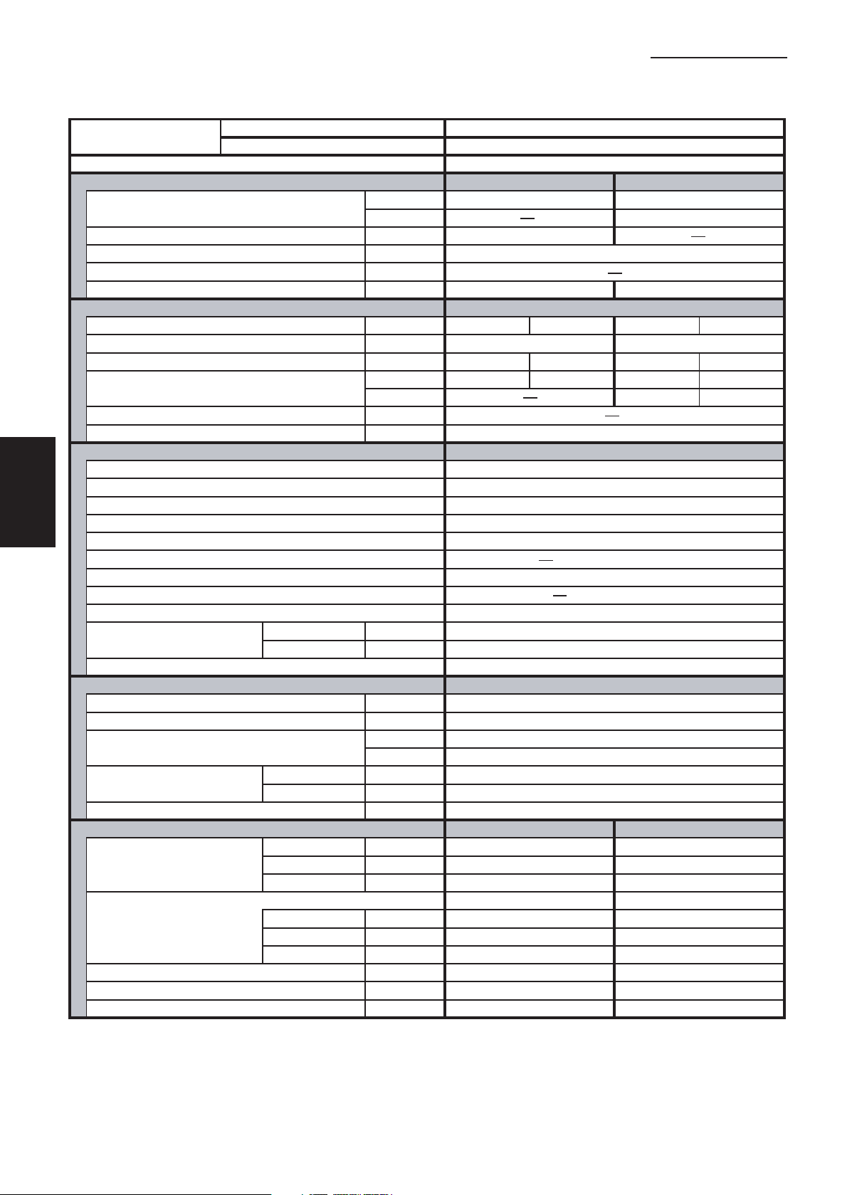
1-1 Unit Specifications
Concealed-Duct Type
1. Specifications
MODEL No.
POWER SOURCE
PERFORMANCE
Capacity * [minimum~muximum] BTU / h 24,000 [9,500~24,000] 28,600 [8,000~28,600]
Moisture removal (High) Pints / h 7.7
Air circulation (H / M / L) 230 V CFM 670 / 530 / 460
External Static Pressure
S.E.E.R. / H.S.P.F. (Region 4) BTU / Wh 14.0 9.7
ELECTRICAL RATINGS
Voltage rating V 230 208 230 208
Available voltage range V VAC 187 - 253 VAC 187 - 253
Max. Running amperes*
Power input W 2,600 2,600 2,400 2,400
Back-up Heater kW
Maximum overcurrent protection (Indoor/Outdoor)
FEATURES
Controls Microprocessor
Low ambient control Built-in 0˚F
Fan speeds Indoor / Outdoor 3 and Automatic control / Variable
Optional Wired Remote Controller
Optional Wireless Remote Controller RCS-BH80UA. WL
Air deflection (Horizontal / Vertical )
Air filter
Drain pump (Drain connection)
Compressor Rotary(SANYO)
Operation sound
Refrigerant control Electronic Expansion Valve (MOV)
REFRIGERANT TUBING
Limit of tubing length ft. (m) 165 (50)
Limit of tubing length at shipment ft. (m) 10~100 (3~30)
Limit of elevation difference ft. (m) Outdoor unit is higher than indoor unit : 100 (30)
between the two units ft. (m) Outdoor unit is lower than indoor unit : 50 (15)
Refrigerant tube Narrow tube in. (mm) 3 / 8 (6.35)
outer diameter Wide tube in. (mm) 5 / 8 (15.88)
Refrigerant amount at shipment lbs. (kg) 4.19 (1.9) - R410A
DIMENSIONS & WEIGHT
Unit dimensions Height in. (mm) 12-7/32 (310) 30- 23/32 (780)
Package dimensions Indoor unit Outdoor unit
Net weight lbs. (kg) 71 (32) 128 (58)
Shipping weight lbs. (kg) 82 (37) 148 (67)
Shipping volume cu.ft. (m 3 ) 11.8 (0.334) 13.0 (0.369)
Cooling:
Rating conditions (*) : Room temperature 80 °F DB / 67 °F WB, Ambient temperature 95 °F DB / 75 °F WB
Indoor Unit UH2672R
Outdoor Unit CH2672R
230 - 208 V / 1 Phase / 60 Hz
Cooling Heating
(17˚F)** BTU / h 17,100
in.WG
A 13.6 15.0 12.5 13.8
(17˚F)** W 1,980 1,980
A 15 / 30
Max.head 2-33/64 in. above drain connection (25A , OD32mm)
Indoor - Hi/Me/Lo
Outdoor - Hi dB - A 49
Width in. (mm) 39-3/8 (1,000) 37 (940)
Depth in. (mm) 24-13/16 (630) 13- 3/8 (340)
Height in. (mm) 14-3/32 (358) 34- 31/32 (888)
Width in. (mm) 46-7/8 (1,191) 39- 31/32 (1,015)
Depth in. (mm) 30-13/16 (783) 16- 3/32 (409)
dB - A 34 / 30 / 27
0.2:at shipment / 0.4:using jumper cable
RCS-SH80UG / RCS-TM80BG
Indoor unit Outdoor unit
DATA SUBJECT TO CHANGE WITHOUT NOTICE.
1
2
3
4
5
Heating:
Rating conditions (*) : Room temperature 70 °F DB / 60 °F WB, Ambient temperature 47 °F DB / 43 °F WB
Low temp conditions (**) : Room temperature 70 °F DB / 60 °F WB, Ambient temperature 17 °F DB / 15 °F WB
I-15
6
SM831148
Page 20
1-1 Unit Specifications
Concealed-Duct Type
1. Specifications
1
2
3
4
5
MODEL No.
POWER SOURCE
PERFORMANCE
Capacity * [minimum~muximum] BTU / h 31,200 [9,500~31,200] 36,200 [8,000~36,200]
Moisture removal (High) Pints / h 10.0
Air circulation (H / M / L) 230 V CFM 670 / 530 / 460
External Static Pressure
S.E.E.R. / H.S.P.F. (Region 4) BTU / Wh 13.9 8.7
ELECTRICAL RATINGS
Voltage rating V 230 208 230 208
Available voltage range V VAC 187 - 253 VAC 187 - 253
Max. Running amperes* A 18.6 20.6 15.9 17.6
Power input W 3,920 3,920 3,340 3,340
Back-up Heater kW
Maximum overcurrent protection (Indoor/Outdoor)
FEATURES
Controls Microprocessor
Low ambient control Built-in 0˚F
Fan speeds Indoor / Outdoor 3 and Automatic control / Variable
Optional Wired Remote Controller
Optional Wireless Remote Controller RCS-BH80UA. WL
Air deflection (Horizontal / Vertical )
Air filter
Drain pump (Drain connection)
Compressor Rotary(SANYO)
Operation sound
Refrigerant control Electronic Expansion Valve (MOV)
REFRIGERANT TUBING
Limit of tubing length ft. (m) 165 (50)
Limit of tubing length at shipment ft. (m) 10~100 (3~30)
Limit of elevation difference ft. (m) Outdoor unit is higher than indoor unit : 100 (30)
between the two units ft. (m) Outdoor unit is lower than indoor unit : 50 (15)
Refrigerant tube Narrow tube in. (mm) 3 / 8 (6.35)
outer diameter Wide tube in. (mm) 5 / 8 (15.88)
Refrigerant amount at shipment lbs. (kg) 6.17 (2.8) - R410A
DIMENSIONS & WEIGHT
Unit dimensions Height in. (mm) 12-7/32 (310) 30- 23/32 (780)
Package dimensions Indoor unit Outdoor unit
Net weight lbs. (kg) 104 (47) 143 (65)
Shipping weight lbs. (kg) 115 (52) 161 (73)
Shipping volume cu.ft. (m 3 ) 16.5 0.468) 13.0 (0.369)
Cooling:
Rating conditions (*) : Room temperature 80 °F DB / 67 °F WB, Ambient temperature 95 °F DB / 75 °F WB
Indoor Unit UH3672R
Outdoor Unit CH3672R
230 - 208 V / 1 Phase / 60 Hz
Cooling Heating
(17˚F)** BTU / h 20,200
in. WG
(17˚F)** W 2,570 2,570
A 15 / 35
Indoor - Hi/Me/Lo
Outdoor - Hi dB - A 52
Width in. (mm) 58-9/32 (1,480) 37 (940)
Depth in. (mm) 24-13/16 (630) 13- 3/8 (340)
Height in. (mm) 14-3/32 (358) 34- 31/32 (888)
Width in. (mm) 65-25/32 (1,671) 39- 31/32 (1,015)
Depth in. (mm) 30-13/16 (783) 16- 3/32 (409)
dB - A 38 / 33 / 31
0.24:at shipment / 0.4:using jumper cable
RCS-SH80UG / RCS-TM80BG
Max.head 2-33/64 in. above drain connection (25A , OD32mm)
Indoor unit Outdoor unit
DATA SUBJECT TO CHANGE WITHOUT NOTICE.
6
Heating:
Rating conditions (*) : Room temperature 70 °F DB / 60 °F WB, Ambient temperature 47 °F DB / 43 °F WB
Low temp conditions (**) : Room temperature 70 °F DB / 60 °F WB, Ambient temperature 17 °F DB / 15 °F WB
SM831148
I-16
Page 21

1-1 Unit Specifications
Concealed-Duct Type
1. Specifications
MODEL No.
POWER SOURCE
PERFORMANCE
Capacity * [minimum~muximum] BTU / h 24,000 [9,500~24,000]
Moisture removal (High) Pints / h 7.7
Air circulation (H / M / L) 230 V CFM 670 / 530 / 460
External Static Pressure
S.E.E.R. / H.S.P.F. (Region 4) BTU / Wh 14.0
ELECTRICAL RATINGS
Voltage rating V 230 208
Available voltage range V VAC 187 - 253
Max. Running amperes*
Power input W 2,600 2,600
Back-up Heater kW
Maximum overcurrent protection (Indoor/Outdoor)
FEATURES
Controls Microprocessor
Low ambient control Built-in 0˚F
Fan speeds Indoor / Outdoor 3 and Automatic control / Variable
Optional Wired Remote Controller
Optional Wireless Remote Controller RCS-BH80UA. WL
Air deflection (Horizontal / Vertical ) —
Air filter
Drain pump (Drain connection)
Compressor Rotary(SANYO)
Operation sound
Refrigerant control Electronic Expansion Valve (MOV)
REFRIGERANT TUBING
Limit of tubing length ft. (m) 165 (50)
Limit of tubing length at shipment ft. (m) 10~100 (3~30)
Limit of elevation difference ft. (m) Outdoor unit is higher than indoor unit : 100 (30)
between the two units ft. (m) Outdoor unit is lower than indoor unit : 50 (15)
Refrigerant tube Narrow tube in. (mm) 3 / 8 (6.35)
outer diameter Wide tube in. (mm) 5 / 8 (15.88)
Refrigerant amount at shipment lbs. (kg) 4.19 (1.9) - R410A
DIMENSIONS & WEIGHT
Unit dimensions Height in. (mm) 12-7/32 (310) 30- 23/32 (780)
Package dimensions Indoor unit Outdoor unit
Net weight lbs. (kg) 71 (32) 128 (58)
Shipping weight lbs. (kg) 82 (37) 148 (67)
Shipping volume cu.ft. (m 3 ) 11.8 (0.334) 13.0 (0.369)
Cooling:
Rating conditions (*) : Room temperature 80 °F DB / 67 °F WB, Ambient temperature 95 °F DB / 75 °F WB
Indoor Unit UH2672R
Outdoor Unit C2672R
230 - 208 V / 1 Phase / 60 Hz
Cooling
(17˚F)** BTU / h
in. WG
A 13.6 15.0
(17˚F)** W
A 15 / 30
Max.head 2-33/64 in. above drain connection (25A , OD32mm)
Indoor - Hi/Me/Lo
Outdoor - Hi dB - A 49
Width in. (mm) 39-3/8 (1,000) 37 (940)
Depth in. (mm) 24-13/16 (630) 13- 3/8 (340)
Height in. (mm) 14-3/32 (358) 34- 31/32 (888)
Width in. (mm) 46-7/8 (1,191) 39- 31/32 (1,015)
Depth in. (mm) 30-13/16 (783) 16- 3/32 (409)
dB - A 34 / 30 / 27
0.2:at shipment / 0.4:using jumper cable
RCS-SH80UG / RCS-TM80BG
Indoor unit Outdoor unit
DATA SUBJECT TO CHANGE WITHOUT NOTICE.
—
—
—
—
1
2
3
4
5
Heating:
Rating conditions (*) : Room temperature 70 °F DB / 60 °F WB, Ambient temperature 47 °F DB / 43 °F WB
Low temp conditions (**) : Room temperature 70 °F DB / 60 °F WB, Ambient temperature 17 °F DB / 15 °F WB
I-17
6
SM831148
Page 22

1-1 Unit Specifications
Concealed-Duct Type
1. Specifications
1
2
3
4
5
MODEL No.
POWER SOURCE
PERFORMANCE
Capacity * [minimum~muximum] BTU / h 31,200 [9,500~31,200]
Moisture removal (High) Pints / h 10.0
Air circulation (H / M / L) 230 V CFM 670 / 530 / 460
External Static Pressure
S.E.E.R. / H.S.P.F. (Region 4) BTU / Wh 13.9
ELECTRICAL RATINGS
Voltage rating V 230 208
Available voltage range V VAC 187 - 253
Max. Running amperes* A 18.6 20.6
Power input W 3,920 3,920
Back-up Heater kW
Maximum overcurrent protection (Indoor/Outdoor)
FEATURES
Controls Microprocessor Microprocessor
Low ambient control Built-in 0˚F
Fan speeds Indoor / Outdoor 3 and Automatic control / Variable
Optional Wired Remote Controller
Optional Wireless Remote Controller RCS-SH1UA / RCS-BH80UA. WL
Air deflection (Horizontal / Vertical ) —
Air filter
Drain pump (Drain connection)
Compressor Rotary(SANYO)
Operation sound
Refrigerant control Electronic Expansion Valve (MOV)
REFRIGERANT TUBING
Limit of tubing length ft. (m) 165 (50)
Limit of tubing length at shipment ft. (m) 10~100 (3~30)
Limit of elevation difference ft. (m) Outdoor unit is higher than indoor unit : 100 (30)
between the two units ft. (m) Outdoor unit is lower than indoor unit : 50 (15)
Refrigerant tube Narrow tube in. (mm) 3 / 8 (6.35)
outer diameter Wide tube in. (mm) 5 / 8 (15.88)
Refrigerant amount at shipment lbs. (kg) 6.17 (2.8) - R410A
DIMENSIONS & WEIGHT
Unit dimensions Height in. (mm) 12-7/32 (310) 30- 23/32 (780)
Package dimensions Indoor unit Outdoor unit
Net weight lbs. (kg) 104 (47) 143 (65)
Shipping weight lbs. (kg) 115 (52) 161 (73)
Shipping volume cu.ft. (m 3 ) 16.5 0.468) 13.0 (0.369)
Cooling:
Rating conditions (*) : Room temperature 80 °F DB / 67 °F WB, Ambient temperature 95 °F DB / 75 °F WB
Indoor Unit UH3672R
Outdoor Unit C3672R
230 - 208 V / 1 Phase / 60 Hz
Cooling
(17˚F)** BTU / h
in. WG
(17˚F)** W
A 15 / 35
Indoor - Hi/Me/Lo
Outdoor - Hi dB - A 52
Width in. (mm) 58-9/32 (1,480) 37 (940)
Depth in. (mm) 24-13/16 (630) 13- 3/8 (340)
Height in. (mm) 14-3/32 (358) 34- 31/32 (888)
Width in. (mm) 65-25/32 (1,671) 39- 31/32 (1,015)
Depth in. (mm) 30-13/16 (783) 16- 3/32 (409)
dB - A 38 / 33 / 31
0.24:at shipment / 0.4:using jumper cable
RCS-SH80UG / RCS-TM80BG
Max.head 2-33/64 in. above drain connection (25A , OD32mm)
Indoor unit Outdoor unit
DATA SUBJECT TO CHANGE WITHOUT NOTICE.
—
—
—
—
6
Heating:
Rating conditions (*) : Room temperature 70 °F DB / 60 °F WB, Ambient temperature 47 °F DB / 43 °F WB
Low temp conditions (**) : Room temperature 70 °F DB / 60 °F WB, Ambient temperature 17 °F DB / 15 °F WB
SM831148
I-18
Page 23
1-1 Unit Specifications
Ceiling-Mounted Type
1. Specifications
MODEL No.
POWER SOURCE
PERFORMANCE
Capacity * [minimum~muximum] BTU / h 24,400 [9,500~24,400] 30,800 [8,000~30,800]
Moisture removal (High) Pints / h 7.7
Air circulation (H / M / L) 230 V CFM 550 / 490 / 460
External Static Pressure in. WG
S.E.E.R. / H.S.P.F. (Region 4) BTU / Wh 14.5 10.3
ELECTRICAL RATINGS
Voltage rating V 230 208 230 208
Available voltage range V VAC 187 - 253 VAC 187 - 253
Max. Running amperes* (Without Back-up Heater)
Power input W 2,880 2,880 3,000 3,000
Back-up Heater kW 1.8 1.47
Maximum overcurrent protection (Indoor/Outdoor)
FEATURES
Controls Microprocessor
Low ambient control Built-in 0˚F
Fan speeds Indoor / Outdoor 3 and Automatic control / Variable
Optional Wired Remote Controller
Optional Wireless Remote Controller RCS-SH80UA. WL / RCS-BH80UA. WL
Air deflection (Horizontal / Vertical )
Air filter Washable, long life (2,500 hr)
Drain pump (Drain connection) (20A , OD26mm)
Compressor Rotary(SANYO)
Operation sound
Refrigerant control Electronic Expansion Valve (MOV)
REFRIGERANT TUBING
Limit of tubing length ft. (m) 165 (50)
Limit of tubing length at shipment ft. (m) 10~100 (3~30)
Limit of elevation difference ft. (m) Outdoor unit is higher than indoor unit : 100 (30)
between the two units ft. (m) Outdoor unit is lower than indoor unit : 50 (15)
Refrigerant tube Narrow tube in. (mm) 3 / 8 (6.35)
outer diameter Wide tube in. (mm) 5 / 8 (15.88)
Refrigerant amount at shipment lbs. (kg) 4.19 (1.9) - R410A
DIMENSIONS & WEIGHT
Unit dimensions Height in. (mm) 7-17/32 (190) 30- 23/32 (780)
Package dimensions Indoor unit Outdoor unit
Net weight lbs. (kg) 64 (29) 128 (58)
Shipping weight lbs. (kg) 75 (34) 148 (67)
Shipping volume cu.ft. (m 3 ) 8.9 (0.253) 13.0 (0.369)
Cooling:
Rating conditions (*) : Room temperature 80 °F DB / 67 °F WB, Ambient temperature 95 °F DB / 75 °F WB
Indoor Unit THH2672R
Outdoor Unit CH2672R
230 - 208 V / 1 Phase / 60 Hz
Cooling Heating
(17˚F)** BTU / h 17,900
A 15.6 17.3 16.4 18.1
(17˚F)** W 2,190 2,190
A 15 / 30
RCS-SH80UG / RCS-TM80BG
/ Automatic (Vertical )
Indoor - Hi/Me/Lo
Outdoor - Hi dB - A 49
Width in. (mm) 51-3/16 (1,300) 37 (940)
Depth in. (mm) 26-3/8 (670) 13- 3/8 (340)
Height in. (mm) 9-7/16 (240) 34- 31/32 (888)
Width in. (mm) 54-19/32 (1,387) 39- 31/32 (1,015)
Depth in. (mm) 31-1/16 (789) 16- 3/32 (409)
dB - A 39 / 37 / 33
Indoor unit Outdoor unit
DATA SUBJECT TO CHANGE WITHOUT NOTICE.
1
2
3
4
5
Heating:
Rating conditions (*) : Room temperature 70 °F DB / 60 °F WB, Ambient temperature 47 °F DB / 43 °F WB
Low temp conditions (**) : Room temperature 70 °F DB / 60 °F WB, Ambient temperature 17 °F DB / 15 °F WB
I-19
6
SM831148
Page 24

1-1 Unit Specifications
Ceiling-Mounted Type
1. Specifications
1
2
3
4
5
MODEL No.
POWER SOURCE
PERFORMANCE
Capacity * [minimum~muximum] BTU / h 24,400 [9,500~24,400] 30,800 [8,000~30,800]
Moisture removal (High) Pints / h 7.7
Air circulation (H / M / L) 230 V CFM 550 / 490 / 460
External Static Pressure
S.E.E.R. / H.S.P.F. (Region 4) BTU / Wh 14.5 10.3
ELECTRICAL RATINGS
Voltage rating V 230 208 230 208
Available voltage range V VAC 187 - 253 VAC 187 - 253
Max. Running amperes* (Without Back-up Heater)
Power input W 2,880 2,880 3,000 3,000
Back-up Heater kW
Maximum overcurrent protection (Indoor/Outdoor)
FEATURES
Controls Microprocessor Microprocessor
Low ambient control Built-in 0˚F
Fan speeds Indoor / Outdoor 3 and Automatic control / Variable
Optional Wired Remote Controller
Optional Wireless Remote Controller RCS-SH80UA. WL / RCS-BH80UA. WL
Air deflection (Horizontal / Vertical )
Air filter Washable, long life (2,500 hr)
Drain pump (Drain connection) (20A , OD26mm)
Compressor Rotary(SANYO)
Operation sound
Refrigerant control Electronic Expansion Valve (MOV)
REFRIGERANT TUBING
Limit of tubing length ft. (m) 165 (50)
Limit of tubing length at shipment ft. (m) 10~100 (3~30)
Limit of elevation difference ft. (m) Outdoor unit is higher than indoor unit : 100 (30)
between the two units ft. (m) Outdoor unit is lower than indoor unit : 50 (15)
Refrigerant tube Narrow tube in. (mm) 3 / 8 (6.35)
outer diameter Wide tube in. (mm) 5 / 8 (15.88)
Refrigerant amount at shipment lbs. (kg) 4.19 (1.9) - R410A
DIMENSIONS & WEIGHT
Unit dimensions Height in. (mm) 7-17/32 (190) 30- 23/32 (780)
Package dimensions Indoor unit Outdoor unit
Net weight lbs. (kg) 57 (26) 128 (58)
Shipping weight lbs. (kg) 68 (31) 148 (67)
Shipping volume cu.ft. (m 3 ) 8.9 (0.253) 13.0 (0.369)
Cooling:
Rating conditions (*) : Room temperature 80 °F DB / 67 °F WB, Ambient temperature 95 °F DB / 75 °F WB
Indoor Unit TH2672R
Outdoor Unit CH2672R
230 - 208 V / 1 Phase / 60 Hz
Cooling Heating
(17˚F)** BTU / h 17,900
in. WG
A 15.6 17.3 16.4 18.1
(17˚F)** W 2,190 2,190
A 15 / 30
RCS-SH80UG / RCS-TM80BG
/ Automatic (Vertical )
Indoor - Hi/Me/Lo
Outdoor - Hi dB - A 49
Width in. (mm) 51-3/16 (1,300) 37 (940)
Depth in. (mm) 26-3/8 (670) 13- 3/8 (340)
Height in. (mm) 9-7/16 (240) 34- 31/32 (888)
Width in. (mm) 54-19/32 (1,387) 39- 31/32 (1,015)
Depth in. (mm) 31-1/16 (789) 16- 3/32 (409)
dB - A 39 / 37 / 33
Indoor unit Outdoor unit
DATA SUBJECT TO CHANGE WITHOUT NOTICE.
6
Heating:
Rating conditions (*) : Room temperature 70 °F DB / 60 °F WB, Ambient temperature 47 °F DB / 43 °F WB
Low temp conditions (**) : Room temperature 70 °F DB / 60 °F WB, Ambient temperature 17 °F DB / 15 °F WB
SM831148
I-20
Page 25
1-1 Unit Specifications
Ceiling-Mounted Type
1. Specifications
MODEL No.
POWER SOURCE
PERFORMANCE
Capacity * [minimum~muximum] BTU / h 31,200 [9,500~31,200] 37,400 [8,000~37,400]
Moisture removal (High) Pints / h 10.0
Air circulation (H / M / L) 230 V CFM 1100 / 930 / 750
External Static Pressure
S.E.E.R. / H.S.P.F. (Region 4) BTU / Wh 15.1 9.6
ELECTRICAL RATINGS
Voltage rating V 230 208 230 208
Available voltage range V VAC 187 - 253 VAC 187 - 253
Max. Running amperes* A 18.2 20.1 15.6 17.3
Power input W 3,840 3,840 3,250 3,250
Back-up Heater kW 2.4 1.95
Maximum overcurrent protection (Indoor/Outdoor)
FEATURES
Controls Microprocessor Microprocessor
Low ambient control Built-in 0˚F
Fan speeds Indoor / Outdoor 3 and Automatic control / Variable
Optional Wired Remote Controller
Optional Wireless Remote Controller RCS-SH80UA. WL / RCS-BH80UA. WL
Air deflection (Horizontal / Vertical )
Air filter Washable, long life (2,500 hr)
Drain pump (Drain connection) (20A , OD26mm)
Compressor Rotary(SANYO)
Operation sound
Refrigerant control Electronic Expansion Valve (MOV)
REFRIGERANT TUBING
Limit of tubing length ft. (m) 165 (50)
Limit of tubing length at shipment ft. (m) 10~100 (3~30)
Limit of elevation difference ft. (m) Outdoor unit is higher than indoor unit : 100 (30)
between the two units ft. (m) Outdoor unit is lower than indoor unit : 50 (15)
Refrigerant tube Narrow tube in. (mm) 3 / 8 (6.35)
outer diameter Wide tube in. (mm) 5 / 8 (15.88)
Refrigerant amount at shipment lbs. (kg) 6.17 (2.8) - R410A
DIMENSIONS & WEIGHT
Unit dimensions Height in. (mm) 9-7/16 (240) 30- 23/32 (780)
Package dimensions Indoor unit Outdoor unit
Net weight lbs. (kg) 90 (41) 143 (65)
Shipping weight lbs. (kg) 104 (47) 161 (73)
Shipping volume cu.ft. (m 3 ) 14.8 (0.420) 13.0 (0.369)
Cooling:
Rating conditions (*) : Room temperature 80 °F DB / 67 °F WB, Ambient temperature 95 °F DB / 75 °F WB
Indoor Unit THH3672R
Outdoor Unit CH3672R
230 - 208 V / 1 Phase / 60 Hz
Cooling Heating
(17˚F)** BTU / h 21,000
in. WG
(17˚F)** W 2,470 2,470
A 15 / 35
RCS-SH80UG / RCS-TM80BG
/ Automatic (Vertical )
Indoor - Hi/Me/Lo
Outdoor - Hi dB - A 52
Width in. (mm) 62-1/32 (1,575) 37 (940)
Depth in. (mm) 26-3/8 (670) 13- 3/8 (340)
Height in. (mm) 12-15/32 (317) 34- 31/32 (888)
Width in. (mm) 66-1/16 (1,678) 39- 31/32 (1,015)
Depth in. (mm) 31-1/16 (789) 16- 3/32 (409)
dB - A 42 / 40 / 35
Indoor unit Outdoor unit
DATA SUBJECT TO CHANGE WITHOUT NOTICE.
1
2
3
4
5
Heating:
Rating conditions (*) : Room temperature 70 °F DB / 60 °F WB, Ambient temperature 47 °F DB / 43 °F WB
Low temp conditions (**) : Room temperature 70 °F DB / 60 °F WB, Ambient temperature 17 °F DB / 15 °F WB
I-21
6
SM831148
Page 26
1-1 Unit Specifications
Ceiling-Mounted Type
1. Specifications
1
2
3
4
5
MODEL No.
POWER SOURCE
PERFORMANCE
Capacity * [minimum~muximum] BTU / h 31,200 [9,500~31,200] 37,400 [8,000~37,400]
Moisture removal (High) Pints / h 10.0
Air circulation (H / M / L) 230 V CFM 1100 / 930 / 750
External Static Pressure
S.E.E.R. / H.S.P.F. (Region 4) BTU / Wh 15.1 9.6
ELECTRICAL RATINGS
Voltage rating V 230 208 230 208
Available voltage range V VAC 187 - 253 VAC 187 - 253
Max. Running amperes* A 18.2 20.1 15.6 17.3
Power input W 3,840 3,840 3,250 3,250
Back-up Heater kW
Maximum overcurrent protection (Indoor/Outdoor)
FEATURES
Controls Microprocessor
Low ambient control Built-in 0˚F
Fan speeds Indoor / Outdoor 3 and Automatic control / Variable
Optional Wired Remote Controller
Optional Wireless Remote Controller RCS-SH80UA. WL / RCS-BH80UA. WL
Air deflection (Horizontal / Vertical )
Air filter Washable, long life (2,500 hr)
Drain pump (Drain connection) (20A , OD26mm)
Compressor Rotary(SANYO)
Operation sound
Refrigerant control Electronic Expansion Valve (MOV)
REFRIGERANT TUBING
Limit of tubing length ft. (m) 165 (50)
Limit of tubing length at shipment ft. (m) 10~100 (3~30)
Limit of elevation difference ft. (m) Outdoor unit is higher than indoor unit : 100 (30)
between the two units ft. (m) Outdoor unit is lower than indoor unit : 50 (15)
Refrigerant tube Narrow tube in. (mm) 3 / 8 (6.35)
outer diameter Wide tube in. (mm) 5 / 8 (15.88)
Refrigerant amount at shipment lbs. (kg) 6.17 (2.8) - R410A
DIMENSIONS & WEIGHT
Unit dimensions Height in. (mm) 9-7/16 (240) 30- 23/32 (780)
Package dimensions Indoor unit Outdoor unit
Net weight lbs. (kg) 84 (38) 143 (65)
Shipping weight lbs. (kg) 97 (44) 161 (73)
Shipping volume cu.ft. (m 3 ) 14.8 (0.420) 13.0 (0.369)
Cooling:
Rating conditions (*) : Room temperature 80 °F DB / 67 °F WB, Ambient temperature 95 °F DB / 75 °F WB
Indoor Unit TH3672R
Outdoor Unit CH3672R
230 - 208 V / 1 Phase / 60 Hz
Cooling Heating
(17˚F)** BTU / h 21,000
in. WG
(17˚F)** W 2,470 2,470
A 15 / 35
RCS-SH80UG / RCS-TM80BG
/ Automatic (Vertical )
Indoor - Hi/Me/Lo
Outdoor - Hi dB - A 52
Width in. (mm) 62-1/32 (1,575) 37 (940)
Depth in. (mm) 26-3/8 (670) 13- 3/8 (340)
Height in. (mm) 12-15/32 (317) 34- 31/32 (888)
Width in. (mm) 66-1/16 (1,678) 39- 31/32 (1,015)
Depth in. (mm) 31-1/16 (789) 16- 3/32 (409)
dB - A 42 / 40 / 35
Indoor unit Outdoor unit
DATA SUBJECT TO CHANGE WITHOUT NOTICE.
6
Heating:
Rating conditions (*) : Room temperature 70 °F DB / 60 °F WB, Ambient temperature 47 °F DB / 43 °F WB
Low temp conditions (**) : Room temperature 70 °F DB / 60 °F WB, Ambient temperature 17 °F DB / 15 °F WB
SM831148
I-22
Page 27

1-1 Unit Specifications
Ceiling-Mounted Type
1. Specifications
MODEL No.
POWER SOURCE
PERFORMANCE
Capacity * [minimum~muximum] BTU / h 39,000 [9,500~39,000] 44,500 [8,000~44,500]
Moisture removal (High) Pints / h 12.6
Air circulation (H / M / L) 230 V CFM 1100 / 930 / 750
External Static Pressure
S.E.E.R. / H.S.P.F. (Region 4) BTU / Wh 15.6 10.2
ELECTRICAL RATINGS
Voltage rating V 230 208 230 208
Available voltage range V VAC 187 - 253 VAC 187 - 253
Max. Running amperes* A 21.1 23.3 18.6 20.6
Power input W 4,140 4,140 3,630 3,630
Back-up Heater kW
Maximum overcurrent protection (Indoor/Outdoor)
FEATURES
Controls Microprocessor
Low ambient control Built-in 0˚F
Fan speeds Indoor / Outdoor 3 and Automatic control / Variable
Optional Wired Remote Controller
Optional Wireless Remote Controller RCS-SH80UA. WL / RCS-BH80UA. WL
Air deflection (Horizontal / Vertical )
Air filter Washable, long life (2,500 hr)
Drain pump (Drain connection) (20A , OD26mm)
Compressor Rotary(SANYO)
Operation sound
Refrigerant control Electronic Expansion Valve (MOV)
REFRIGERANT TUBING
Limit of tubing length ft. (m) 165 (50)
Limit of tubing length at shipment ft. (m) 10~100 (3~30)
Limit of elevation difference ft. (m) Outdoor unit is higher than indoor unit : 100 (30)
between the two units ft. (m) Outdoor unit is lower than indoor unit : 50 (15)
Refrigerant tube Narrow tube in. (mm) 3 / 8 (6.35)
outer diameter Wide tube in. (mm) 5 / 8 (15.88)
Refrigerant amount at shipment lbs. (kg) 7.94 (3.6) - R410A
DIMENSIONS & WEIGHT
Unit dimensions Height in. (mm) 9-7/16 (240) 48-7/16 (1,230 )
Package dimensions Indoor unit Outdoor unit
Net weight lbs. (kg) 84 (38) 220 (100)
Shipping weight lbs. (kg) 97 (44) 240 (109 )
Shipping volume cu.ft. (m 3 ) 14.8 (0.420) 19.5 (0.552 )
Cooling:
Rating conditions (*) : Room temperature 80 °F DB / 67 °F WB, Ambient temperature 95 °F DB / 75 °F WB
Indoor Unit TH4272R
Outdoor Unit CH4272R
230 - 208 V / 1 Phase / 60 Hz
Cooling Heating
(17˚F)** BTU / h 28,800
in. WG
(17˚F)** W 3,110 3,110
A 15 / 40
RCS-SH80UG / RCS-TM80BG
/ Automatic (Vertical )
Indoor - Hi/Me/Lo
Outdoor - Hi dB - A 53
Width in. (mm) 62-1/32 (1,575) 37 (940)
Depth in. (mm) 26-3/8 (670) 13- 3/8 (340)
Height in. (mm) 12-15/32 (317) 52-3/8 (1,330 )
Width in. (mm) 66-1/16 (1,678) 39- 31/32 (1,015)
Depth in. (mm) 31-1/16 (789) 16- 3/32 (409)
dB - A 44 / 41 / 37
Indoor unit Outdoor unit
DATA SUBJECT TO CHANGE WITHOUT NOTICE.
1
2
3
4
5
Heating:
Rating conditions (*) : Room temperature 70 °F DB / 60 °F WB, Ambient temperature 47 °F DB / 43 °F WB
Low temp conditions (**) : Room temperature 70 °F DB / 60 °F WB, Ambient temperature 17 °F DB / 15 °F WB
I-23
6
SM831148
Page 28
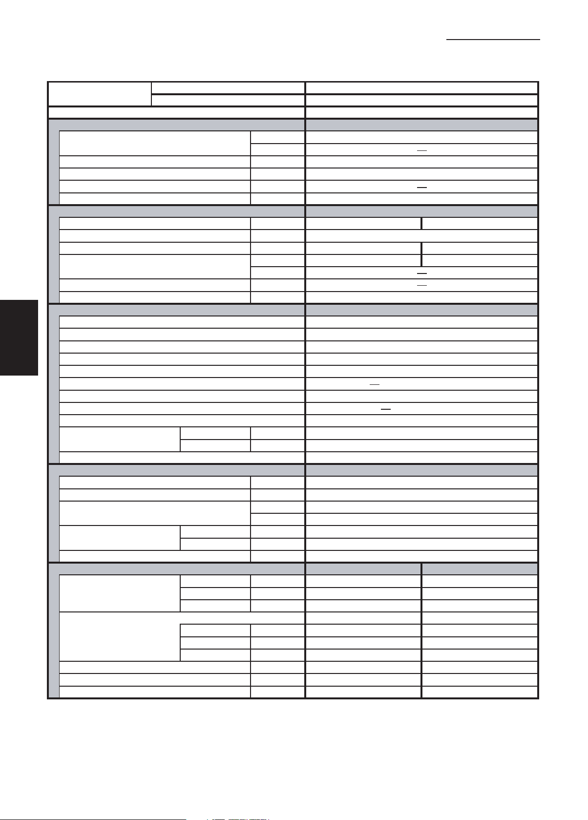
1-1 Unit Specifications
Ceiling-Mounted Type
1. Specifications
1
2
3
4
5
MODEL No.
POWER SOURCE
PERFORMANCE
Capacity * [minimum~muximum] BTU / h 24,400 [9,500~24,400]
Moisture removal (High) Pints / h 7.7
Air circulation (H / M / L) 230 V CFM 550 / 490 / 460
External Static Pressure
S.E.E.R. / H.S.P.F. (Region 4) BTU / Wh 14.5
ELECTRICAL RATINGS
Voltage rating V 230 208
Available voltage range V VAC 187 - 253
Max. Running amperes* (Without Back-up Heater)
Power input W 2,880 2,880
Back-up Heater kW
Maximum overcurrent protection (Indoor/Outdoor)
FEATURES
Controls Microprocessor
Low ambient control Built-in 0˚F
Fan speeds Indoor / Outdoor 3 and Automatic control / Variable
Optional Wired Remote Controller
Optional Wireless Remote Controller RCS-SH80UA. WL / RCS-BH80UA. WL
Air deflection (Horizontal / Vertical )
Air filter Washable, long life (2,500 hr)
Drain pump (Drain connection) (20A , OD26mm)
Compressor Rotary(SANYO)
Operation sound
Refrigerant control Electronic Expansion Valve (MOV)
REFRIGERANT TUBING
Limit of tubing length ft. (m) 165 (50)
Limit of tubing length at shipment ft. (m) 10~100 (3~30)
Limit of elevation difference ft. (m) Outdoor unit is higher than indoor unit : 100 (30)
between the two units ft. (m) Outdoor unit is lower than indoor unit : 50 (15)
Refrigerant tube Narrow tube in. (mm) 3 / 8 (6.35)
outer diameter Wide tube in. (mm) 5 / 8 (15.88)
Refrigerant amount at shipment lbs. (kg) 4.19 (1.9) - R410A
DIMENSIONS & WEIGHT
Unit dimensions Height in. (mm) 7-17/32 (190) 30- 23/32 (780)
Package dimensions Indoor unit Outdoor unit
Net weight lbs. (kg) 57 (26) 128 (58)
Shipping weight lbs. (kg) 68 (31) 148 (67)
Shipping volume cu.ft. (m 3 ) 8.9 (0.253) 13.0 (0.369)
Cooling:
Rating conditions (*) : Room temperature 80 °F DB / 67 °F WB, Ambient temperature 95 °F DB / 75 °F WB
Indoor Unit TH2672R
Outdoor Unit C2672R
230 - 208 V / 1 Phase / 60 Hz
Cooling
(17˚F)** BTU / h
in. WG
A 15.6 17.3
(17˚F)** W
A 15 / 30
RCS-SH80UG / RCS-TM80BG
/ Automatic (Vertical )
Indoor - Hi/Me/Lo
Outdoor - Hi dB - A 49
Width in. (mm) 51-3/16 (1,300) 37 (940)
Depth in. (mm) 26-3/8 (670) 13- 3/8 (340)
Height in. (mm) 9-7/16 (240) 34- 31/32 (888)
Width in. (mm) 54-19/32 (1,387) 39- 31/32 (1,015)
Depth in. (mm) 31-1/16 (789) 16- 3/32 (409)
dB - A 39 / 37 / 33
Indoor unit Outdoor unit
DATA SUBJECT TO CHANGE WITHOUT NOTICE.
6
Heating:
Rating conditions (*) : Room temperature 70 °F DB / 60 °F WB, Ambient temperature 47 °F DB / 43 °F WB
Low temp conditions (**) : Room temperature 70 °F DB / 60 °F WB, Ambient temperature 17 °F DB / 15 °F WB
SM831148
I-24
Page 29
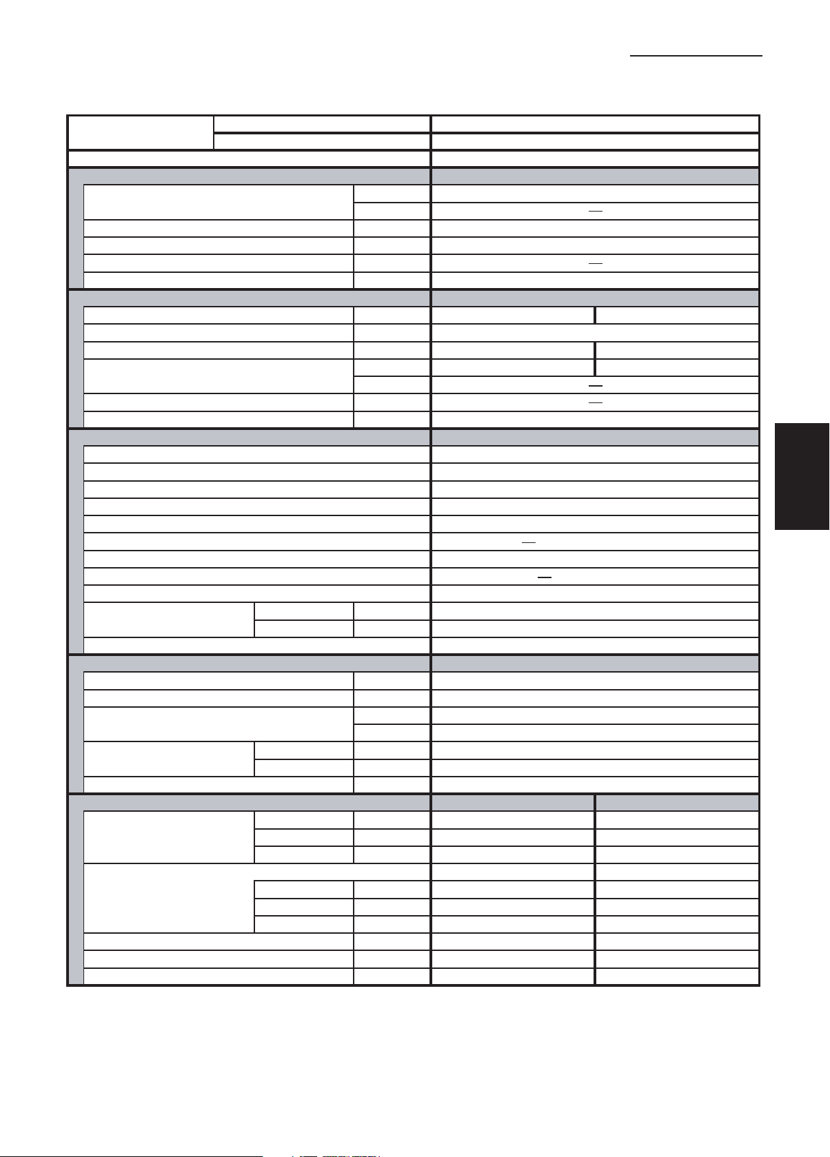
1-1 Unit Specifications
Ceiling-Mounted Type
1. Specifications
MODEL No.
POWER SOURCE
PERFORMANCE
Capacity * [minimum~muximum] BTU / h 31,200 [9,500~31,200]
Moisture removal (High) Pints / h 10.0
Air circulation (H / M / L) 230 V CFM 1100 / 930 / 750
External Static Pressure
S.E.E.R. / H.S.P.F. (Region 4) BTU / Wh 15.1
ELECTRICAL RATINGS
Voltage rating V 230 208
Available voltage range V VAC 187 - 253
Max. Running amperes* A 18.2 20.1
Power input W 3,840 3,840
Back-up Heater kW
Maximum overcurrent protection (Indoor/Outdoor)
FEATURES
Controls Microprocessor
Low ambient control Built-in 0˚F
Fan speeds Indoor / Outdoor 3 and Automatic control / Variable
Optional Wired Remote Controller
Optional Wireless Remote Controller RCS-SH80UA. WL / RCS-BH80UA. WL
Air deflection (Horizontal / Vertical )
Air filter Washable, long life (2,500 hr)
Drain pump (Drain connection) (20A , OD26mm)
Compressor Rotary(SANYO)
Operation sound
Refrigerant control Electronic Expansion Valve (MOV)
REFRIGERANT TUBING
Limit of tubing length ft. (m) 165 (50)
Limit of tubing length at shipment ft. (m) 10~100 (3~30)
Limit of elevation difference ft. (m) Outdoor unit is higher than indoor unit : 100 (30)
between the two units ft. (m) Outdoor unit is lower than indoor unit : 50 (15)
Refrigerant tube Narrow tube in. (mm) 3 / 8 (6.35)
outer diameter Wide tube in. (mm) 5 / 8 (15.88)
Refrigerant amount at shipment lbs. (kg) 6.17 (2.8) - R410A
DIMENSIONS & WEIGHT
Unit dimensions Height in. (mm) 9-7/16 (240) 30- 23/32 (780)
Package dimensions Indoor unit Outdoor unit
Net weight lbs. (kg) 84 (38) 143 (65)
Shipping weight lbs. (kg) 97 (44) 161 (73)
Shipping volume cu.ft. (m 3 ) 14.8 (0.420) 13.0 (0.369)
Cooling:
Rating conditions (*) : Room temperature 80 °F DB / 67 °F WB, Ambient temperature 95 °F DB / 75 °F WB
Indoor Unit TH3672R
Outdoor Unit C3672R
230 - 208 V / 1 Phase / 60 Hz
Cooling
(17˚F)** BTU / h
in. WG
(17˚F)** W
A 15 / 35
RCS-SH80UG / RCS-TM80BG
/ Automatic (Vertical )
Indoor - Hi/Me/Lo
Outdoor - Hi dB - A 52
Width in. (mm) 62-1/32 (1,575) 37 (940)
Depth in. (mm) 26-3/8 (670) 13- 3/8 (340)
Height in. (mm) 12-15/32 (317) 34- 31/32 (888)
Width in. (mm) 66-1/16 (1,678) 39- 31/32 (1,015)
Depth in. (mm) 31-1/16 (789) 16- 3/32 (409)
dB - A 42 / 40 / 35
Indoor unit Outdoor unit
DATA SUBJECT TO CHANGE WITHOUT NOTICE.
1
2
3
4
5
Heating:
Rating conditions (*) : Room temperature 70 °F DB / 60 °F WB, Ambient temperature 47 °F DB / 43 °F WB
Low temp conditions (**) : Room temperature 70 °F DB / 60 °F WB, Ambient temperature 17 °F DB / 15 °F WB
I-25
6
SM831148
Page 30

1-1 Unit Specifications
Ceiling-Mounted Type
1. Specifications
1
2
3
4
5
MODEL No.
POWER SOURCE
PERFORMANCE
Capacity * [minimum~muximum] BTU / h 39,000 [9,500~39,000]
Moisture removal (High) Pints / h 12.6
Air circulation (H / M / L) 230 V CFM 1100 / 930 / 750
External Static Pressure
S.E.E.R. / H.S.P.F. (Region 4) BTU / Wh 15.6
ELECTRICAL RATINGS
Voltage rating V 230 208
Available voltage range V VAC 187 - 253
Max. Running amperes* A 21.1 23.3
Power input W 4,140 4,140
Back-up Heater kW
Maximum overcurrent protection (Indoor/Outdoor)
FEATURES
Controls Microprocessor
Low ambient control Built-in 0˚F
Fan speeds Indoor / Outdoor 3 and Automatic control / Variable
Optional Wired Remote Controller
Optional Wireless Remote Controller RCS-SH80UA. WL / RCS-BH80UA. WL
Air deflection (Horizontal / Vertical )
Air filter Washable, long life (2,500 hr)
Drain pump (Drain connection) (20A , OD26mm)
Compressor Rotary(SANYO)
Operation sound
Refrigerant control Electronic Expansion Valve (MOV)
REFRIGERANT TUBING
Limit of tubing length ft. (m) 165 (50)
Limit of tubing length at shipment ft. (m) 10~100 (3~30)
Limit of elevation difference ft. (m) Outdoor unit is higher than indoor unit : 100 (30)
between the two units ft. (m) Outdoor unit is lower than indoor unit : 50 (15)
Refrigerant tube Narrow tube in. (mm) 3 / 8 (6.35)
outer diameter Wide tube in. (mm) 5 / 8 (15.88)
Refrigerant amount at shipment lbs. (kg) 7.94 (3.6) - R410A
DIMENSIONS & WEIGHT
Unit dimensions Height in. (mm) 9-7/16 (240) 48-7/16 (1,230 )
Package dimensions Indoor unit Outdoor unit
Net weight lbs. (kg) 84 (38) 220 (100)
Shipping weight lbs. (kg) 97 (44) 240 (109 )
Shipping volume cu.ft. (m 3 ) 14.8 (0.420) 19.5 (0.552 )
Cooling:
Rating conditions (*) : Room temperature 80 °F DB / 67 °F WB, Ambient temperature 95 °F DB / 75 °F WB
Indoor Unit TH4272R
Outdoor Unit C4272R
230 - 208 V / 1 Phase / 60 Hz
Cooling
(17˚F)** BTU / h
in. WG
(17˚F)**
Indoor - Hi/Me/Lo
Outdoor - Hi dB - A 53
Width in. (mm) 62-1/32 (1,575) 37 (940)
Depth in. (mm) 26-3/8 (670) 13- 3/8 (340)
Height in. (mm) 12-15/32 (317) 52-3/8 (1,330 )
Width in. (mm) 66-1/16 (1,678) 39- 31/32 (1,015)
Depth in. (mm) 31-1/16 (789) 16- 3/32 (409)
W
A 15 / 40
RCS-SH80UG / RCS-TM80BG
/ Automatic (Vertical )
dB - A 44 / 41 / 37
Indoor unit Outdoor unit
DATA SUBJECT TO CHANGE WITHOUT NOTICE.
6
Heating:
Rating conditions (*) : Room temperature 70 °F DB / 60 °F WB, Ambient temperature 47 °F DB / 43 °F WB
Low temp conditions (**) : Room temperature 70 °F DB / 60 °F WB, Ambient temperature 17 °F DB / 15 °F WB
SM831148
I-26
Page 31

1-2 Major Component Specifications
(A) Indoor Unit
MODEL No. XH2672R
Source 230 - 208 VAC / 1 phase / 60 Hz
Remote controller (Option) Wired or Wireless (See Unit Specification)
Controller P. C. B Ass'y CR - TH2672
Control circuit fuse 250 VAC, 5 A
Fan (Number … diameter) in. (mm) Turbo (1…17-7/16 (443))
Fan motor
Model SFG6X - 41D6P
Source 230 - 208 V / 1 phase / 60 Hz
No. of pole … r.p.m. (230 V, High) rpm 6 … 464
Nominal output W 40
Coil resistance Ω BRW - WHT : 170.3 , ORG - YEL : 43.2
(Ambient temperature 68 °F) WHT - VLT : 18.1 , WHT - PNK : 83.5
VLT - ORG : 43.2 , YEL - BLK : 60.2
Safety device
Operating temperature Open °F 266 ± 14.4
Close °F 174.2 ± 27
Run capacitor VAC, µF 440 V , 4.5 µF
Heat exchanger
Coil Aluminum plate fin / Copper tube
Rows … Fins per inch 2 … 14.9
Face area ft.
Panel
Model No. PNR - XH2442
Auto louver motor MT8 - 3C
Auto louver motor … Rated V, W, rpm 240 VAC , 3 W , 3 rpm
Coil resistance (Ambient temperature 77 °F) Ω 16.430 Ω ± 8 %
2
(m2) 3.69 (0.343)
DATA SUBJECT TO CHANGE WITHOUT NOTICE
1. Specifications
1
2
I-27
3
4
5
6
SM831148
Page 32

1
2
1-2 Major Component Specifications
(A) Indoor Unit
MODEL No. XH3672R
Source 230 - 208 VAC / 1 phase / 60 Hz
Remote controller (Option) Wired or Wireless (See Unit Specification)
Controller P. C. B Ass'y CR - TH2672
Control circuit fuse 250 VAC, 5 A
Fan (Number … diameter) in. (mm) Turbo (1…17-7/16 (443))
Fan motor
Model SFG6X - 81A6P
Source 230 - 208 V / 1 phase / 60 Hz
No. of pole … r.p.m. (230 V, High) rpm 6 … 467
Nominal output W 60
Coil resistance Ω BRW - WHT : 75.1 , ORG - YEL : 27.4
(Ambient temperature 68 °F) WHT - VLT : 6.7 , VLT - PNK : 42.7
VLT - ORG : 20.6 , YEL - BLK : 58.0
Safety device
Operating temperature Open °F 266 ± 14.4
Close °F 174.2 ± 27
Run capacitor VAC, µF 440 V , 5 µF
Heat exchanger
Coil Aluminum plate fin / Copper tube
Rows … Fins per inch 2 … 14.9
Face area ft.
Panel
Model No. PNR - XH3642
Auto louver motor MT8 - 3C
Auto louver motor … Rated V, W, rpm 240 VAC , 3 W , 3 rpm
Coil resistance (Ambient temperature 77 °F) Ω 16.430 Ω ± 8 %
2
(m2) 8.20 (0.762)
DATA SUBJECT TO CHANGE WITHOUT NOTICE
1. Specifications
3
4
5
6
SM831148
I-28
Page 33

1-2 Major Component Specifications
(A) Indoor Unit
MODEL No. XH4272R
Source 230 - 208 VAC / 1 phase / 60 Hz
Remote controller (Option) Wired or Wireless (See Unit Specification)
Controller P. C. B Ass'y CR - TH2672
Control circuit fuse 250 VAC, 5 A
Fan (Number … diameter) in. (mm) Turbo (1…17-7/16 (443))
Fan motor
Model SFG6X - 81A6P
Source 230 - 208 V / 1 phase / 60 Hz
No. of pole … r.p.m. (230 V, High) rpm 6 … 506
Nominal output W 60
Coil resistance Ω BRW - WHT : 75.1 , ORG - YEL : 27.4
(Ambient temperature 68 °F) WHT - VLT : 6.7 , VLT - PNK : 42.7
VLT - ORG : 20.6 , YEL - BLK : 58.0
Safety device
Operating temperature Open °F266± 14.4
Close °F 174.2 ± 27
Run capacitor VAC, µF 440 V , 6 µF
Heat exchanger
Coil Aluminum plate fin / Copper tube
Rows … Fins per inch 2 … 14.9
Face area ft.
Panel
Model No. PNR - XH3642
Auto louver motor MT8 - 3C
Auto louver motor … Rated V, W, rpm 240 VAC , 3 W , 3 rpm
Coil resistance (Ambient temperature 77 °F) Ω 16.430 Ω ± 8 %
2
(m2) 8.20 (0.762)
DATA SUBJECT TO CHANGE WITHOUT NOTICE
1. Specifications
1
2
I-29
3
4
5
6
SM831148
Page 34

1
2
1-2 Major Component Specifications
(A) Indoor Unit
MODEL No. TH2672R
Source 230 - 208 V / 1 phase / 60 Hz
Remote controller (Option) Wired or Wireless (See Unit Specification)
Controller P. C. B Ass'y CR - TH2672
Control circuit fuse 250 V, 5 A
Fan (Number … diameter) in. (mm) Centrifugal (4 ... 5-1/8(130))
Fan motor
Model SR4X - 51A6P
Source 230 - 208 V / 1 phase / 60 Hz
No. of pole … r.p.m. (230 V, High) rpm 1,179
Nominal output W 31
Coil resistance Ω BRW - WHT : 111.0 , ORG - YEL : 16.7
(Ambient temperature 68 °F) WHT - VLT : 35.4 , BLK - PNK : 23.9
VLT - ORG : 13.4 , YEL - BLK : 136.6
Safety device
Operating temperature Open °F266± 14.4
Close °F 174.2 ± 27
Run capacitor VAC, µF 440 V , 1.5 µF
Heat exchanger
Coil Aluminum plate fin / Copper tube
Rows … Fins per inch 3 … 14.9
Face area ft.
Auto louver motor
Model No. MT8 - 3C
Auto louver motor … Rated V, W, rpm 240 VAC , 3 W , 3 rpm
Coil resistance (Ambient temperature 77 °F) Ω 16,430 Ω ± 8 %
2
(m2) 1.81 (0.168)
DATA SUBJECT TO CHANGE WITHOUT NOTICE
1. Specifications
3
4
5
6
SM831148
I-30
Page 35

1-2 Major Component Specifications
(A) Indoor Unit
MODEL No. TH3672R
Source 230 - 208 V / 1 phase / 60 Hz
Remote controller (Option) Wired or Wireless (See Unit Specification)
Controller P. C. B Ass'y CR - TH2672
Control circuit fuse 250 V, 5 A
Fan (Number … diameter) in. (mm) Centrifugal (4 ... 5-29/32(150))
Fan motor
Model KFG4X - 101C6P
Source 230 - 208 V / 1 phase / 60 Hz
No. of pole … r.p.m. (230 V, High) rpm 4 ... 1,040
Nominal output W 100
Coil resistance Ω BRW - WHT : 61.05 , ORG - YEL : 13.23
(Ambient temperature 68 °F) WHT - VLT : 9.955 , YEL - BLK : 19.25
VLT - ORG : 9.576 , BLK - PNK : 10.81
Safety device
Operating temperature Open °F 266 ± 14.4
Close °F 174.2 ± 27
Run capacitor VAC, µF 440 V , 4 µF
Heat exchanger
Coil Aluminum plate fin / Copper tube
Rows … Fins per inch 3 … 14.9
Face area ft.
Auto louver motor
Model No. MT8 - 3C
Auto louver motor … Rated V, W, rpm 240 VAC , 3 W , 3 rpm
Coil resistance (Ambient temperature 77 °F) Ω 16,430 Ω ± 8 %
2
(m2) 3.51 (0.326)
DATA SUBJECT TO CHANGE WITHOUT NOTICE
1. Specifications
1
2
I-31
3
4
5
6
SM831148
Page 36

1
2
1-2 Major Component Specifications
(A) Indoor Unit
MODEL No. TH4272R
Source 230 - 208 V / 1 phase / 60 Hz
Remote controller (Option) Wired or Wireless (See Unit Specification)
Controller P. C. B Ass'y CR - TH2672
Control circuit fuse 250 V, 5 A
Fan (Number … diameter) in. (mm) Centrifugal (4 ... 5-29/32(150))
Fan motor
Model KFG4X - 101C6P
Source 230 - 208 V / 1 phase / 60 Hz
No. of pole … r.p.m. (230 V, High) rpm 4 ... 1,099
Nominal output W 100
Coil resistance Ω BRW - WHT : 61.05 , ORG - YEL : 13.23
(Ambient temperature 68 °F) WHT - VLT : 9.955 , YEL - BLK : 19.25
VLT - ORG : 9.576 , BLK - PNK : 10.81
Safety device
Operating temperature Open °F266± 14.4
Close °F 174.2 ± 27
Run capacitor VAC, µF 440 V , 5 µF
Heat exchanger
Coil Aluminum plate fin / Copper tube
Rows … Fins per inch 3 … 14.9
Face area ft.
Auto louver motor
Model No. MT8 - 3C
Auto louver motor … Rated V, W, rpm 240 VAC , 3 W , 3 rpm
Coil resistance (Ambient temperature 77 °F) Ω 16,430 Ω ± 8 %
2
(m2) 3.51 (0.326)
DATA SUBJECT TO CHANGE WITHOUT NOTICE
1. Specifications
3
4
5
6
SM831148
I-32
Page 37

1-2 Major Component Specifications
(A) Indoor Unit
MODEL No. THH2672R
Source 230 - 208 V / 1 phase / 60 Hz
Remote controller (Option) Wired or Wireless (See Unit Specification)
Controller P. C. B Ass'y CR - TH2672
Control circuit fuse 250 V, 5 A
Fan (Number ... diameter) in. (mm)
Fan motor
Model
Source
No. of pole ... r.p.m. (230 V, High) rpm 1,187
Nominal output W 31
Coil resistance Ω
(Ambient temperature 68 °F)
Safety device
Operating temperature Open °F266± 14.4
Close °F 174.2 ± 27
Run capacitor VAC, µF 440 V , 1.5 µF
Heater Ass'y (Aux. Heater)
Model AH - 1.8THS2432
Input (230 / 208 V) KW
Protective thermostat CS- 12AL OFF 122 ± 6°F, ON 104 ± 10°F
Thermo fuse SF96U Cut - off 205 ± 4°F
Heat exchanger
Coil Aluminum plate fin / Copper tube
Rows ... Fins per inch 3 ... 14.9
Face area ft.
Auto louver motor
Model No. MT8 - 3C
Auto louver motor ... Rated V, W, rpm 240 VAC , 3 W , 3 rpm
Coil resistance (Ambient temperature 77 °F) Ω 16,430 Ω ± 8 %
2
(m2) 1.81 (0.168)
BRW - WHT : 111.0 , ORG - YEL : 16.7
WHT - VLT : 35.4 , BLK - PNK : 23.9
VLT - ORG : 13.4 , YEL - BLK : 136.6
Centrifugal (4 ... 5-1/8(130))
SR4X - 51A6P
230 - 208 V / 1 phase / 60 Hz
1.8 / 1.45
DATA SUBJECT TO CHANGE WITHOUT NOTICE
1. Specifications
1
2
3
I-33
4
5
6
SM831148
Page 38

1
2
3
1-2 Major Component Specifications
(A) Indoor Unit
MODEL No. THH3672R
Source 230 - 208 V / 1 phase / 60 Hz
Remote controller (Option) Wired or Wireless (See Unit Specification)
Controller P. C. B Ass'y CR - TH2672
Control circuit fuse 250 V, 5 A
Fan (Number ... diameter) in. (mm)
Fan motor
Model
Source
No. of pole ... r.p.m. (230 V, High) rpm 4 ... 1,015
Nominal output W 100
Coil resistance Ω
(Ambient temperature 68 °F)
Safety device
Operating temperature Open °F266± 14.4
Close °F 174.2 ± 27
Run capacitor VAC, µF 440 V , 4 µF
Heater Ass'y (Aux. Heater)
Model AH - 2.4THS3632
Input (230 / 208 V) KW
Protective thermostat CS- 12AL OFF 122 ± 6°F, ON 104 ± 10°F
Thermo fuse SF96U Cut - off 205 ± 4°F
Heat exchanger
Coil Aluminum plate fin / Copper tube
Rows ... Fins per inch 3 ... 14.9
Face area ft.
Auto louver motor
Model No. MT8 - 3C
Auto louver motor ... Rated V, W, rpm 240 VAC , 3 W , 3 rpm
Coil resistance (Ambient temperature 77 °F) Ω 16,430 Ω ± 8 %
2
(m2) 3.51 (0.326)
BRW - WHT : 61.05 , ORG - YEL : 13.23
WHT - VLT : 9.955 , YEL - BLK : 19.25
VLT - ORG : 9.576 , BLK - PNK : 10.81
Centrifugal (4 ... 5-29/32(150))
KFG4X - 101C6P
230 - 208 V / 1 phase / 60 Hz
2.4 / 1.94
DATA SUBJECT TO CHANGE WITHOUT NOTICE
1. Specifications
4
5
6
SM831148
I-34
Page 39

1-2 Major Component Specifications
(A) Indoor Unit
MODEL No. UH2672R
Source 230 - 208 V / 1 phase / 60 Hz
Remote controller (Option) Wired or Wireless (See Unit Specification)
Controller P. C. B Ass'y CR - TH2672
Control circuit fuse 250 V, 5 A
Fan (Number … diameter) in. (mm) Centrifugal (4 ... 5-29/32(150))
Fan motor
Model KFG4X - 71B6P
Source 230 - 208 V / 1 phase / 60 Hz
No. of pole … r.p.m. (230 V, High) rpm 4 ... 920
Nominal output W 100
Coil resistance Ω BRW - WHT : 74.7 , ORG - YEL : 9.59
(Ambient temperature 68 °F) WHT - VLT : 19.1 , YEL - BLK : 10.52
VLT - ORG : 10.5 , BLK - PNK : 21.72
Safety device
Operating temperature Open °F266± 14.4
Close °F 174.2 ± 27
Run capacitor VAC, µF 440 V , 5 µF
Heat exchanger
Coil Aluminum plate fin / Copper tube
Rows … Fins per inch 3 … 14.9
2
Face area ft.
(m2) 2.03 (0.189)
DATA SUBJECT TO CHANGE WITHOUT NOTICE
1. Specifications
1
2
3
4
5
I-35
6
SM831148
Page 40

1
1-2 Major Component Specifications
(A) Indoor Unit
MODEL No. UH3672R
Source 230 - 208 V / 1 phase / 60 Hz
Remote controller (Option) Wired or Wireless (See Unit Specification)
Controller P. C. B Ass'y CR - TH2672
Control circuit fuse 250 V, 5 A
Fan (Number … diameter) in. (mm) Centrifugal (4 ... 5-29/32(150))
Fan motor
Model KFG4X - 141A6P
Source 230 - 208 V / 1 phase / 60 Hz
No. of pole ... r.p.m. (230 V, High) rpm 4 ... 940
Nominal output W 100
Coil resistance Ω BRW - WHT : 39.9 , ORG - YEL : 9.37
(Ambient temperature 68 °F) WHT - VLT : 6.91 , YEL - BLK : 8.86
VLT - ORG : 11.4 , BLK - PNK : 14.3
Safety device
Operating temperature Open °F 266 ± 14.4
Close °F 174.2 ± 27
Run capacitor VAC, µF 440 V , 5 µF
Heat exchanger
Coil Aluminum plate fin / Copper tube
Rows ... Fins per inch 3 ... 12.7
Face area ft.
2
(m2) 3.32 (0.308)
DATA SUBJECT TO CHANGE WITHOUT NOTICE
1. Specifications
2
3
4
5
6
SM831148
I-36
Page 41

1-2 Major Component Specifications
(A) Indoor Unit
MODEL No. KH2672R
Source 230 - 208 V / 1 phase / 60 Hz
Remote controller (Option) Wired or Wireless (See Unit Specification)
Controller P. C. B Ass'y CB - KR24GXH56A
Control circuit fuse 250 V, 5 A
Fan Cross-flow
Number ... Dia. and length in. (mm) 1 ... O.D. 4-1/3 (110), L39 (990)
Fan motor
Model KFT4Q - 31A6P - C
Source 230 - 208 V / 1 phase / 60 Hz
No. of pole ... r.p.m. (230 V, High) rpm 4 ... 1,224
Nominal output W 28.8
Coil resistance Ω BRW - WHT : 260.7 , ORG - YEL : 23.76
(Ambient temperature 68 °F) WHT - VLT : 42.62 , YEL - PNK : 115.9
VLT - ORG : 30.36 ,
Safety device
Operating temperature Open °F ± 14.4
Close °F 174.2 ± 26
Run capacitor VAC, µF 440 V , 1.8 µF
Heat exchanger
Coil Aluminum plate fin / Copper tube
Rows ... Fins per inch 2 ... 24.1
2
Face area ft.
(m2) 2.57 (0.24)
DATA SUBJECT TO CHANGE WITHOUT NOTICE
266
1. Specifications
1
2
I-37
3
4
5
6
SM831148
Page 42

1
2
3
1-2 Major Component Specifications
(A) Indoor Unit
MODEL No. KH3072R
Source 230 - 208 V / 1 phase / 60 Hz
Remote controller (Option) Wired or Wireless (See Unit Specification)
Controller P. C. B Ass'y CR - TH2672
Control circuit fuse 250 V, 5 A
Fan Cross-flow
Number ... Dia. and length in. (mm) 1 ... O.D. 4-13/18 (120), L46 (1,170)
Fan motor
Model SGF4Q - 41D6P
Source 230 - 208 V / 1 phase / 60 Hz
No. of pole ... r.p.m. (230 V, High) rpm 4 ... 1,275
Nominal output W 50
Coil resistance Ω GRY - WHT : 125.4 , ORG - YEL : 23.93
(Ambient temperature 68 °F) WHT - VLT : 20.69 , YEL - PNK : 9.39
VLT - ORG : 11.31 ,
Safety device
Operating temperature Open °F 266 ± 14.4
Close °F 174.2 ± 26
Run capacitor VAC, µF 440 V , 4.5 µF
Heat exchanger
Coil Aluminum plate fin / Copper tube
Rows ... Fins per inch 2 ... 12.7
Face area ft.
Louver Motor
Model M2EA24ZA01
Rating 208 to 230 V, 60 Hz
No. of pole ... rpm 8 ... 3
Output W 2.5
Coil resistance (Ambient temperature 68 °F) kΩ 16.45 ± 8 %
2
(m2) 3.23 (0.3)
DATA SUBJECT TO CHANGE WITHOUT NOTICE
1. Specifications
4
5
6
SM831148
I-38
Page 43

1. Specifications
1-2 Major Component Specifications
(A) Indoor Unit
MODEL No. KH3672R
Source 230 - 208 V / 1 phase / 60 Hz
Remote controller (Option) Wired or Wireless (See Unit Specification)
Controller P. C. B Ass'y CR - TH2672
Control circuit fuse 250 V, 5 A
Fan Cross-flow
Number ... Dia. and length in. (mm) 1 ... O.D. 4-13/18 (120), L46 (1,170)
Fan motor
Model SFG4Q - 41B6P
Source 230 - 208 V / 1 phase / 60 Hz
No. of pole ... r.p.m. (230 V, High) rpm 4 ... 1,273
Nominal output W 50
Coil resistance Ω GRY - WHT : 122.3 , ORG - YEL : 23.03
(Ambient temperature 68 °F) WHT - VLT : 15.98 , YEL - PNK : 9.272
VLT - ORG : 11.93 ,
Safety device
Operating temperature Open °F 266 ± 14.4
Close °F 174.2 ± 26
Run capacitor VAC, µF 440 V , 4 µF
Heat exchanger
Coil Aluminum plate fin / Copper tube
Rows ... Fins per inch 3 ... 12.7
Face area ft.
Louver Motor
Model M2EA24ZA01
Rating 208 to 230 V, 60 Hz
No. of pole ... rpm 8 ... 3
Output W 2.5
Coil resistance (Ambient temperature 68 °F) kΩ 16.45 ± 8 %
2
(m2) 3.23 (0.3)
DATA SUBJECT TO CHANGE WITHOUT NOTICE
1
2
3
I-39
4
5
6
SM831148
Page 44

1
2
3
4
1-2 Major Component Specifications
(A) Indoor Unit
MODEL No. KHH2672R
Source 230 - 208 V / 1 phase / 60 Hz
Remote controller (Option) Wired or Wireless (See Unit Specification)
Controller P. C. B Ass'y CR - TH2672
Control circuit fuse 250 V, 5 A
Fan Cross-flow
Number ... Dia. and length in. (mm) 1 ... O.D. 4-1/3 (110), L39 (990)
Fan motor
Model UF4Q - 31A6P
Source 230 - 208 V / 1 phase / 60 Hz
No. of pole ... r.p.m. (230 V, High) rpm 4 ... 1,277
Nominal output W 30
Coil resistance Ω BRW - WHT : 197.2 , ORG - YEL : 59.1
(Ambient temperature 68 °F) WHT - VLT : 41.4 , YEL - PNK : 48.8
VLT - ORG : 22.2 ,
Safety device
Operating temperature Open °F248± 9
Close °F171± 27
Run capacitor VAC, µF 440 V , 1.8 µF
Heater Element (Aux. Heater)
Model AH - KH2412
Input (230 / 208 V) KW
Protective thermostat OFF 140 ± 5°F, ON 113 ± 9°F
Thermo fuse Cut - off 370 + 2, - 5°F, 277V - 15A
Heat exchanger
Coil Aluminum plate fin / Copper tube
Rows ... 3 ... 12.7
Face area ft.
Louver Motor
Model M2EA24ZA01
Rating 208 to 230 V, 60 Hz
No. of pole ... rpm 8 ... 3
Output W 2.5
Coil resistance (Ambient temperature 68 °F) kΩ 16.45 ± 8 %
2
(m2) 2.57 (0.24)
DATA SUBJECT TO CHANGE WITHOUT NOTICE
1.8 / 1.5
1. Specifications
5
6
SM831148
I-40
Page 45

1-2 Major Component Specifications
(B) Outdoor Unit
MODEL No.
Source
Controller P.C.B. Ass'y
Control circuit fuse (on the P.C.B.“FIL-CH4872R”)
Compressor
Model....number
Nominal output W
Compressor oil cc
Coil resistance Ω C – R : 0.665 R – S : 0.665
°
(Ambient temperature 25
Safety control
Microprocessor safety devices
Overload protector
(Operating temperature)
Crank case heater
Refrigerant amount at shipment lbs. (kg)
High pressure switch
C) C – S : 0.665
Open
Close
°
F (°C)
°
F (°C)
208 - 230 V / 1 phase / 60 Hz
Compressor Discharge Gas temperature control
Comressor current detection circuit
CH2672R
CR-CH4872R (Microprocessor)
280 V, 25 A
C-7RVN153H0V
1,500
650
230 (110)
203 (95)
–
R410A - 4.19 (1.9)
–
1. Specifications
Set pressure OFF
ON
Fan
Number.. diameter mm
Air circulation (Hi)
Fan speeds (Max.)
Fan motor
Model No.
Source
No. of pole
Nominal output W
Coil resistance Ω RED – WHT : 30.5 WHT – BLK : 30.5
°
(Ambient temperature 20
Safety device
Operating temperature Open
Run capacitor VAC, µF
Heat exchanger
Coil
Rows....fin pitch mm
Face area
C) BLK – RED : 30.5
Close
PSi
PSi
m
°
F (°C)
°
F (°C)
m
600
456
Propeller
1.... ø460
3
/h
~800 rpm (Inverter drive control)
Aluminium plate fin / Copper tube
2
3,000
DAJ12-95B61A (-C, -CR)
DC340 V / 3 phase
8
90
284 (140)
–
–
1....1.6
0.675
1
2
3
4
I-41
5
6
SM831148
Page 46

1-2 Major Component Specifications
(B) Outdoor Unit
MODEL No.
Source
Controller P.C.B. Ass'y
Control circuit fuse (on the P.C.B.“FIL-CH4872R”)
Compressor
Model....number
Nominal output W
Compressor oil cc
Coil resistance Ω C – R : 0.665 R – S : 0.665
°
(Ambient temperature 25
Safety control
Microprocessor safety devices
Overload protector
(Operating temperature)
Crank case heater
Refrigerant amount at shipment
High pressure switch
C) C – S : 0.665
Compressor Discharge Gas temperature control
Comressor current detection circuit
Open
Close
°
F (°C)
°
F (°C)
lbs. (kg)
CH3072R / CH3672R
208 - 230 V / 1 phase / 60 Hz
CR-CH4872R (Microprocessor)
280 V, 25 A
C-7RVN153H0V
1,500
650
230 (110)
203 (95)
–
R410A - 5.73 (2.6) / 6.17 (2.8)
–
1. Specifications
1
2
3
4
Set pressure OFF
ON
Fan
Number.. diameter mm
Air circulation (Hi)
Fan speeds (Max.)
Fan motor
Model No.
Source
No. of pole
Nominal output W
Coil resistance Ω RED – WHT : 30.5 WHT – BLK : 30.5
°
(Ambient temperature 20
Safety device
Operating temperature Open
Run capacitor VAC, µF
Heat exchanger
Coil
Rows....fin pitch mm
Face area
C) BLK – RED : 30.5
Close
PSi
PSi
m
°
F (°C)
°
F (°C)
600
456
Propeller
1.... ø460
3
/h
~830 rpm (Inverter drive control)
Aluminium plate fin / Copper tube
2
m
3,300
DAJ12-95B61A (-C, -CR)
DC340 V / 3 phase
8
90
284 (140)
–
–
2....1.8
0.675
5
6
SM831148
I-42
Page 47

1-2 Major Component Specifications
(B) Outdoor Unit
MODEL No.
Source
Controller P.C.B. Ass'y
Control circuit fuse (on the P.C.B.“FIL-CH4872R”)
Compressor
Model....number
Nominal output W
Compressor oil cc
Coil resistance Ω C – R : 0.169 R – S :0.169
°
(Ambient temperature 25
Safety control
Microprocessor safety devices
Overload protector
(Operating temperature)
Crank case heater
Refrigerant amount at shipment
High pressure switch
C) C – S :0.169
Open
Close
°
F (°C)
°
F (°C)
lbs. (kg)
208 - 230 V / 1 phase / 60 Hz
CR-CH4872R (Microprocessor)
Compressor Discharge Gas temperature control
Comressor current detection circuit
CH4272R
280 V, 25 A
C-9RVN273H0W
2,700
1,900
230 (110)
203 (95)
–
R410A - 7.94 (3.6)
–
1. Specifications
Set pressure OFF
ON
Fan
Number.. diameter mm
Air circulation (Hi)
Fan speeds (Max.)
Fan motor
Model No.
Source
No. of pole
Nominal output W
Coil resistance Ω RED – WHT : 30.5 WHT – BLK : 30.5
°
(Ambient temperature 20
Safety device
Operating temperature Open
Run capacitor VAC,
Heat exchanger
Coil
Rows....fin pitch mm
Face area
C) BLK – RED : 30.5
Close
PSi
PSi
m
°
F (°C)
°
F (°C)
µF
600
456
Propeller
2.... ø460
3
/h
~830 rpm (Inverter drive control)
DAJ12-95B61A, B (-C, -CR)
Aluminium plate fin / Copper tube
2
m
6,000
DC340 V / 3 phase
8
90
284 (140)
–
–
2....2.0
1.080
1
2
3
4
I-43
5
6
SM831148
Page 48

1-2 Major Component Specifications
(B) Outdoor Unit
MODEL No.
Source
Controller P.C.B. Ass'y
Control circuit fuse (on the P.C.B.“FIL-CH4872R”)
Compressor
Model....number
Nominal output W
Compressor oil cc
Coil resistance Ω C – R : 0.665 R – S : 0.665
°
(Ambient temperature 25
Safety control
Microprocessor safety devices
Overload protector
(Operating temperature)
Crank case heater
Refrigerant amount at shipment lbs. (kg)
High pressure switch
C) C – S : 0.665
Open
Close
°
F (°C)
°
F (°C)
208 - 230 V / 1 phase / 60 Hz
CR-CH4872R (Microprocessor)
Compressor Discharge Gas temperature control
Comressor current detection circuit
C2672R
280 V, 25 A
C-7RVN153H0V
1,500
650
230 (110)
203 (95)
–
R410A - 4.19 (1.9)
–
1. Specifications
1
2
3
4
Set pressure OFF
ON
Fan
Number.. diameter mm
Air circulation (Hi)
Fan speeds (Max.)
Fan motor
Model No.
Source
No. of pole
Nominal output W
Coil resistance Ω RED – WHT : 30.5 WHT – BLK : 30.5
°
(Ambient temperature 20
Safety device
Operating temperature Open
Run capacitor VAC,
Heat exchanger
Coil
Rows....fin pitch mm
Face area
C) BLK – RED : 30.5
Close
PSi
PSi
m
°
F (°C)
°
F (°C)
µF
600
456
Propeller
1.... ø460
3
/h
~800 rpm (Inverter drive control)
Aluminium plate fin / Copper tube
2
m
3,000
DAJ12-95B61A (-C, -CR)
DC340 V / 3 phase
8
90
284 (140)
–
–
1....1.6
0.675
5
6
SM831148
I-44
Page 49

1-2 Major Component Specifications
(B) Outdoor Unit
MODEL No.
Source
Controller P.C.B. Ass'y
Control circuit fuse (on the P.C.B.“FIL-CH4872R”)
Compressor
Model....number
Nominal output W
Compressor oil cc
°
F (°C)
°
F (°C)
Ω
Compressor Discharge Gas temperature control
Comressor current detection circuit
Coil resistance C – R : 0.665 R – S : 0.665
°
(Ambient temperature 25
Safety control
Microprocessor safety devices
Overload protector
(Operating temperature)
Crank case heater
Refrigerant amount at shipment lbs. (kg)
High pressure switch
C) C – S : 0.665
Open
Close
C3072R / C3672R
208 - 230 V / 1 phase / 60 Hz
CR-CH4872R (Microprocessor)
280 V, 25 A
C-7RVN153H0V
1,500
650
230 (110)
203 (95)
–
R410A - 5.73 (2.6) / 6.17 (2.8)
–
1. Specifications
Set pressure OFF
ON
Fan
Number.. diameter mm
Air circulation (Hi)
Fan speeds (Max.)
Fan motor
Model No.
Source
No. of pole
Nominal output W
Coil resistance RED – WHT : 30.5 WHT – BLK : 30.5
°
(Ambient temperature 20
Safety device
Operating temperature Open
Run capacitor VAC,
Heat exchanger
Coil
Rows....fin pitch mm
Face area
C) BLK – RED : 30.5
Close
PSi
PSi
m
°
F (°C)
°
F (°C)
µF
600
456
Propeller
1.... ø460
3
/h
~830 rpm (Inverter drive control)
Ω
Aluminium plate fin / Copper tube
2
m
3,300
DAJ12-95B61A (-C, -CR)
DC340 V / 3 phase
8
90
284 (140)
–
–
2....1.8
0.675
1
2
3
4
I-45
5
6
SM831148
Page 50

1-2 Major Component Specifications
(B) Outdoor Unit
MODEL No.
Source
Controller P.C.B. Ass'y
Control circuit fuse (on the P.C.B.“FIL-CH4872R”)
Compressor
Model....number
Nominal output W
Compressor oil cc
Coil resistance C – R : 0.169 R – S :0.169
°
(Ambient temperature 25
Safety control
Microprocessor safety devices
Overload protector
(Operating temperature)
Crank case heater
Refrigerant amount at shipment
High pressure switch
C) C – S :0.169
Open
Close
Ω
°
F (°C)
°
F (°C)
lbs. (kg)
208 - 230 V / 1 phase / 60 Hz
CR-CH4872R (Microprocessor)
Compressor Discharge Gas temperature control
Comressor current detection circuit
C4272R
280 V, 25 A
C-9RVN273H0W
2,700
1,900
230 (110)
203 (95)
–
R410A - 7.94 (3.6)
–
1. Specifications
1
2
3
4
Set pressure OFF
ON
Fan
Number.. diameter mm
Air circulation (Hi)
Fan speeds (Max.)
Fan motor
Model No.
Source
No. of pole
Nominal output W
Coil resistance RED – WHT : 30.5 WHT – BLK : 30.5
°
(Ambient temperature 20
Safety device
Operating temperature Open
Run capacitor VAC,
Heat exchanger
Coil
Rows....fin pitch mm
Face area
C) BLK – RED : 30.5
Close
PSi
PSi
m
°
F (°C)
°
F (°C)
µF
600
456
Propeller
2.... ø460
3
/h
~830 rpm (Inverter drive control)
DAJ12-95B61A, B (-C, -CR)
Ω
Aluminium plate fin / Copper tube
2
m
6,000
DC340 V / 3 phase
8
90
284 (140)
–
–
2....2.0
1.080
5
6
SM831148
I-46
Page 51

1-3 Other Component Specifications
(A) Indoor Unit
MODEL No. XH2672R
Power Transformer ATR – IIK224A
Rated Primary 220 VAC, 60 Hz
Secondary BRN - BRN : 14 V, 0.45 A, RED - RED : 14 V, 0.3 A
Capacity —
Coil resistance
(Ambient temprature 77 °F) BRN - BRN : 0.97 , ORG - ORG : 3.16
Thermistor cut off temperature °F 277
Thermistor (Coil sensor) : TH2, 3 PBC - 41E - S14
Coil resistance kΩ 14 °F : 23.7 , 41 °F : 12.1
Thermistor (Room sensor) : TH1 KTEC - 35 - S6
Coil resistance kΩ 32 °F : 16.5 , 104 °F : 2.7
Drain pump PJV - 1428AU
Rated 230 / 208 VAC, 12.5 W
Float switch FS - 0218 - 102
MAX Rated (Contact rated) 50 W, DC 5V, 0.1 mA
Synchronized Motor MT8 - 3C
Ω
WHT - WHT : 61.0 , RED - RED : 1.37
23 °F : 18.8 , 50 °F : 9.7
32 °F : 15.0 , 59 °F : 8.0
41 °F : 12.8 , 113 °F : 2.2
50 °F : 10.0 , 122 °F : 1.8
68 °F : 6.3 , 131 °F : 1.5
86 °F : 4.0 ,
1. Specifications
1
2
3
4
5
I-47
6
SM831148
Page 52

1
1. Specifications
1-3 Other Component Specifications
(A) Indoor Unit
MODEL No. XH3672R
Power Transformer ATR – IIK224A
Rated Primary 220 VAC, 60 Hz
Secondary BRN - BRN : 14 V, 0.45 A, RED - RED : 14 V, 0.3 A
Capacity
Coil resistance
(Ambient temprature 77 °F) BRN - BRN : 0.97 , ORG - ORG : 3.16
Thermistor cut off temperature °F277
Thermistor (Coil sensor) : TH2, 3 PBC - 41E - S14
Coil resistance kΩ 14 °F : 23.7 , 41 °F : 12.1
Thermistor (Room sensor) : TH1 KTEC - 35 - S6
Coil resistance kΩ 32 °F : 16.5 , 104 °F : 2.7
Drain pump PJV - 1428AU
Rated 230 / 208 VAC, 12.5 W
Float switch FS - 0218 - 102
MAX Rated (Contact rated) 50 W, DC 5V, 0.1 mA
Synchronized Motor MT8 - 3C
Ω
WHT - WHT : 61.0 , RED—- RED : 1.37
23 °F : 18.8 , 50 °F : 9.7
32 °F : 15.0 , 59 °F : 8.0
41 °F : 12.8 , 113 °F : 2.2
50 °F : 10.0 , 122 °F : 1.8
68 °F : 6.3 , 131 °F : 1.5
86 °F : 4.0 ,
2
3
4
DATA SUBJECT TO CHANGE WITHOUT NOTICE
5
6
SM831148
I-48
Page 53

1-3 Other Component Specifications
(A) Indoor Unit
MODEL No. XH4272R
Power Transformer ATR – IIK224A
Rated Primary 220 VAC, 60 Hz
Secondary BRN - BRN : 14 V, 0.45 A, RED - RED : 14 V, 0.3 A
Capacity —
Coil resistance
(Ambient temprature 77 °F) BRN - BRN : 0.97 , ORG - ORG : 3.16
Thermistor cut off temperature °F 277
Thermistor (Coil sensor) : TH2, 3 PBC - 41E - S14
Coil resistance kΩ 14 °F : 23.7 , 41 °F : 12.1
Thermistor (Room sensor) : TH1 KTEC - 35 - S6
Coil resistance kΩ 32 °F : 16.5 , 104 °F : 2.7
Drain pump PJV - 1428AU
Rated 230 / 208 VAC, 12.5 W
Float switch FS - 0218 - 102
MAX Rated (Contact rated) 50 W, DC 5V, 0.1 mA
Synchronized Motor MT8 - 3C
Ω
WHT - WHT : 61.0 , RED - RED : 1.37
23 °F : 18.8 , 50 °F : 9.7
32 °F : 15.0 , 59 °F : 8.0
41 °F : 12.8 , 113 °F : 2.2
50 °F : 10.0 , 122 °F : 1.8
68 °F : 6.3 , 131 °F : 1.5
86 °F : 4.0 ,
1. Specifications
1
DATA SUBJECT TO CHANGE WITHOUT NOTICE
2
3
4
I-49
5
6
SM831148
Page 54

1
1. Specifications
1-3 Other Component Specifications
(A) Indoor Unit
MODEL No. TH2672R
Power Transformer ATR – IIK244B
Rated Primary AC 220 V, 60 Hz
Secondary BRN - BRN : 14 V / 0.55 A, RED - RED : 14 V / 0.3 A
Capacity
Coil resistance
(Ambient temprature 77 °F) BRN - BRN : 0.45 , ORG - ORG : 2.05
Thermistor cut off temperature °F277
Thermistor (Coil sensor) PBC - 41E - S14
Coil resistance kΩ 14 °F : 23.7 , 59 °F : 8.0
Thermistor (Room or coil sensor) PBC - 41E - S14
Coil resistance kΩ 32 °F : 16.5 , 104 °F : 2.7
Synchronized Motor MT8 - 3C
Ω
WHT - WHT : 48.0 , RED - RED : 0.89
23 °F : 18.8 , 68 °F : 6.5
32 °F : 15.0 , 86 °F : 4.4
41 °F : 12.1 , 104 °F : 3.1
50 °F : 9.7 , 113 °F : 2.6
41 °F : 12.8 , 113 °F : 2.2
50 °F : 10.0 , 122 °F : 1.8
68 °F : 6.3 , 131 °F : 1.5
86 °F : 4.0 ,
DATA SUBJECT TO CHANGE WITHOUT NOTICE
—
2
3
4
5
6
SM831148
I-50
Page 55

1-3 Other Component Specifications
(A) Indoor Unit
MODEL No. TH3672R
Power Transformer ATR – IIK244B
Rated Primary AC 220 V, 60 Hz
Secondary BRN - BRN : 14 V / 0.55 A, RED - RED : 14 V / 0.55 A
Capacity —
Coil resistance
(Ambient temprature 77 °F) BRN - BRN : 0.45 , ORG - ORG : 2.05
Thermistor cut off temperature °F 277
Thermistor (Coil sensor) PBC - 41E - S14
Coil resistance kΩ 14 °F : 23.7 , 59 °F : 8.0
Thermistor (Room or coil sensor) PBC - 41E - S42
Coil resistance kΩ 32 °F : 16.5 , 104 °F : 2.7
Synchronized Motor MT8 - 3C
Ω
WHT - WHT : 48.0 , RED - RED : 0.89
23 °F : 18.8 , 68 °F : 6.5
32 °F : 15.0 , 86 °F : 4.4
41 °F : 12.1 , 104 °F : 3.1
50 °F : 9.7 , 113 °F : 2.6
41 °F : 12.8 , 113 °F : 2.2
50 °F : 10.0 , 122 °F : 1.8
68 °F : 6.3 , 131 °F : 1.5
86 °F : 4.0 ,
DATA SUBJECT TO CHANGE WITHOUT NOTICE
1. Specifications
1
2
3
4
5
I-51
6
SM831148
Page 56

1
1-3 Other Component Specifications
(A) Indoor Unit
MODEL No. TH4272R
Power Transformer ATR – IIK244B
Rated Primary AC 220 V, 60 Hz
Secondary BRN - BRN : 14 V / 0.55 A, RED - RED : 14 V / 0.3 A
Capacity
Coil resistance
(Ambient temprature 77 °F) BRN - BRN : 0.45 , ORG - ORG : 2.05
Thermistor cut off temperature °F 277
Thermistor (Coil sensor) PBC - 41E - S14
Coil resistance kΩ 14 °F : 23.7 , 59 °F : 8.0
Thermistor (Room or coil sensor) KTEC - 35 - S6
Coil resistance kΩ 32 °F : 16.5 , 104 °F : 2.7
Synchronized Motor MT8 - 3C
Ω
WHT - WHT : 48.0 , RED - RED : 0.89
23 °F : 18.8 , 68 °F : 6.5
32 °F : 15.0 , 86 °F : 4.4
41 °F : 12.1 , 104 °F : 3.1
50 °F : 9.7 , 113 °F : 2.6
41 °F : 12.8 , 113 °F : 2.2
50 °F : 10.0 , 122 °F : 1.8
68 °F : 6.3 , 131 °F : 1.5
86 °F : 4.0 ,
DATA SUBJECT TO CHANGE WITHOUT NOTICE
—
1. Specifications
2
3
4
5
6
SM831148
I-52
Page 57

1-3 Other Component Specifications
(A) Indoor Unit
MODEL No. THH2672R
Power Transformer ATR – IIK244B
Rated Primary AC 220 V, 60 Hz
Secondary BRN - BRN : 14 V / 0.55 A, RED - RED : 14 V / 0.3 A
Capacity
Coil resistance
(Ambient temprature 77 °F) BRN - BRN : 0.45 , ORG - ORG : 2.05
Thermistor cut off temperature °F 277
Thermistor (Coil sensor) PBC - 41E - S14
Coil resistance kΩ 14 °F : 23.7 , 59 °F : 8.0
Thermistor (Room or coil sensor) PBC - 41E - S14
Coil resistance kΩ 32 °F : 16.5 , 104 °F : 2.7
Synchronized Motor MT8 - 3C
Ω
WHT - WHT : 48.0 , RED - RED : 0.89
23 °F : 18.8 , 68 °F : 6.5
32 °F : 15.0 , 86 °F : 4.4
41 °F : 12.1 , 104 °F : 3.1
50 °F : 9.7 , 113 °F : 2.6
41 °F : 12.8 , 113 °F : 2.2
50 °F : 10.0 , 122 °F : 1.8
68 °F : 6.3 , 131 °F : 1.5
86 °F : 4.0 ,
DATA SUBJECT TO CHANGE WITHOUT NOTICE
—
1. Specifications
1
2
3
4
5
I-53
6
SM831148
Page 58

1
1-3 Other Component Specifications
(A) Indoor Unit
MODEL No. THH3672R
Power Transformer ATR – IIK244B
Rated Primary AC 220 V, 60 Hz
Secondary BRN - BRN : 14 V / 0.55 A, RED - RED : 14 V / 0.55 A
Capacity
Coil resistance
(Ambient temprature 77 °F) BRN - BRN : 0.45 , ORG - ORG : 2.05
Thermistor cut off temperature °F 277
Thermistor (Coil sensor) PBC - 41E - S14
Coil resistance kΩ 14 °F : 23.7 , 59 °F : 8.0
Thermistor (Room or coil sensor) PBC - 41E - S42
Coil resistance kΩ 32 °F : 16.5 , 104 °F : 2.7
Synchronized Motor MT8 - 3C
Ω
WHT - WHT : 48.0 , RED - RED : 0.89
23 °F : 18.8 , 68 °F : 6.5
32 °F : 15.0 , 86 °F : 4.4
41 °F : 12.1 , 104 °F : 3.1
50 °F : 9.7 , 113 °F : 2.6
41 °F : 12.8 , 113 °F : 2.2
50 °F : 10.0 , 122 °F : 1.8
68 °F : 6.3 , 131 °F : 1.5
86 °F : 4.0 ,
DATA SUBJECT TO CHANGE WITHOUT NOTICE
—
1. Specifications
2
3
4
5
6
SM831148
I-54
Page 59

1-3 Other Component Specifications
(A) Indoor Unit
MODEL No. UH2672R
Power Transformer ATR – IIK244B
Rated Primary AC 220 V, 60 Hz
Secondary BRN - BRN : 14 V / 0.55 A, RED - RED : 14 V / 0.3 A
Capacity
Coil resistance
(Ambient temprature 77 °F) BRN - BRN : 0.45 , ORG - ORG : 2.05
Thermistor cut off temperature °F 277
Thermistor (Coil sensor) PBC - 41E - S36
Coil resistance kΩ 14 °F : 23.7 , 59 °F : 8.0
Thermistor (Room or coil sensor) KTEC - 35 - S42
Coil resistance kΩ 32 °F : 16.5 , 104 °F : 2.7
Ω
WHT - WHT : 48.0 , RED - RED : 0.89
23 °F : 18.8 , 68 °F : 6.5
32 °F : 15.0 , 86 °F : 4.4
41 °F : 12.1 , 104 °F : 3.1
50 °F : 9.7 , 113 °F : 2.6
41 °F : 12.8 , 113 °F : 2.2
50 °F : 10.0 , 122 °F : 1.8
68 °F : 6.3 , 131 °F : 1.5
86 °F : 4.0 ,
DATA SUBJECT TO CHANGE WITHOUT NOTICE
—
1. Specifications
1
2
3
4
5
I-55
6
SM831148
Page 60

1
1-3 Other Component Specifications
(A) Indoor Unit
MODEL No. UH3672R
Power Transformer ATR – IIK244B
Rated Primary AC 220 V, 60 Hz
Secondary BRN - BRN : 14 V / 0.55 A, RED - RED : 14 V / 0.3 A
Capacity
Coil resistance
(Ambient temprature 77 °F) BRN - BRN : 0.45 , ORG - ORG : 2.05
Thermistor cut off temperature °F 277
Thermistor (Coil sensor) PBC - 41E - S36
Coil resistance kΩ 14 °F : 23.7 , 59 °F : 8.0
Thermistor (Room or coil sensor) KTEC - 35 - S85
Coil resistance kΩ 32 °F : 16.5 , 104 °F : 2.7
Ω
WHT - WHT : 48.0 , RED - RED : 0.89
23 °F : 18.8 , 68 °F : 6.5
32 °F : 15.0 , 86 °F : 4.4
41 °F : 12.1 , 104 °F : 3.1
50 °F : 9.7 , 113 °F : 2.6
41 °F : 12.8 , 113 °F : 2.2
50 °F : 10.0 , 122 °F : 1.8
68 °F : 6.3 , 131 °F : 1.5
86 °F : 4.0 ,
DATA SUBJECT TO CHANGE WITHOUT NOTICE
—
1. Specifications
2
3
4
5
6
SM831148
I-56
Page 61

1-3 Other Component Specifications
(A) Indoor Unit
MODEL No. KH2672R
Power Transformer ATR – IIK244D – R
Rated Primary AC 230 V, 60 Hz
Secondary BRN - BRN : 11 V / 1.25 A, RED - RED : 14 V / 0.45 A
Capacity
Coil resistance
(Ambient temprature 77 °F) BRN - BRN : 0.42 , ORG - ORG : 6.11
Thermistor cut off temperature °F 277
Thermistor (Coil sensor) PBC - 41E - S4
Coil resistance kΩ 14 °F : 23.7 , 59 °F : 8.0
Thermistor (Room or coil sensor) KTEC - 35 - S6
Coil resistance kΩ 32 °F : 16.5 , 104 °F : 2.7
Ω
WHT - WHT : 78.5 , RED - RED : 1.95
23 °F : 18.8 , 68 °F : 6.5
32 °F : 15.0 , 86 °F : 4.4
41 °F : 12.1 , 104 °F : 3.1
50 °F : 9.7 , 113 °F : 2.6
41 °F : 12.8 , 113 °F : 2.2
50 °F : 10.0 , 122 °F : 1.8
68 °F : 6.3 , 131 °F : 1.5
86 °F : 4.0 ,
DATA SUBJECT TO CHANGE WITHOUT NOTICE
—
1. Specifications
1
2
3
4
5
I-57
6
SM831148
Page 62

1
1-3 Other Component Specifications
(A) Indoor Unit
MODEL No. KH3072R
Power Transformer ATR – IIK244B
Rated Primary AC 220 V, 60 Hz
Secondary BRN - BRN : 14 V / 0.55 A, RED - RED : 14 V / 0.3 A
Capacity
Coil resistance
(Ambient temprature 77 °F) BRN - BRN : 0.45 , ORG - ORG : 2.05
Thermistor cut off temperature °F 277
Thermistor (Coil sensor) PBC - 41E - S4
Coil resistance kΩ 14 °F : 23.7 , 59 °F : 8.0
Thermistor (Room or coil sensor) KTEC - 35 - S6
Coil resistance kΩ 32 °F : 16.5 , 104 °F : 2.7
Switch Assy's SW - KHS2432
Synchronized Motor M2EA24ZA01
Ω
WHT - WHT : 48.0 , RED - RED : 0.89
23 °F : 18.8 , 68 °F : 6.5
32 °F : 15.0 , 86 °F : 4.4
41 °F : 12.1 , 104 °F : 3.1
50 °F : 9.7 , 113 °F : 2.6
41 °F : 12.8 , 113 °F : 2.2
50 °F : 10.0 , 122 °F : 1.8
68 °F : 6.3 , 131 °F : 1.5
86 °F : 4.0 ,
DATA SUBJECT TO CHANGE WITHOUT NOTICE
—
1. Specifications
2
3
4
5
6
SM831148
I-58
Page 63

1-3 Other Component Specifications
(A) Indoor Unit
MODEL No. KHH2672R
Power Transformer ATR – IIK244B
Rated Primary AC 220 V, 60 Hz
Secondary BRN - BRN : 14 V / 0.55 A, RED - RED : 14 V / 0.3 A
Capacity
Coil resistance
(Ambient temprature 77 °F) BRN - BRN : 0.45 , ORG - ORG : 2.05
Thermistor cut off temperature °F 277
Thermistor (Coil sensor) PBC - 41E - S4
Coil resistance kΩ 14 °F : 23.7 , 59 °F : 8.0
Thermistor (Room or coil sensor) KTEC - 35 - S6
Coil resistance kΩ 32 °F : 16.5 , 104 °F : 2.7
Ω
WHT - WHT : 48.0 , RED - RED : 0.89
23 °F : 18.8 , 68 °F : 6.5
32 °F : 15.0 , 86 °F : 4.4
41 °F : 12.1 , 104 °F : 3.1
50 °F : 9.7 , 113 °F : 2.6
41 °F : 12.8 , 113 °F : 2.2
50 °F : 10.0 , 122 °F : 1.8
68 °F : 6.3 , 131 °F : 1.5
86 °F : 4.0 ,
DATA SUBJECT TO CHANGE WITHOUT NOTICE
—
1. Specifications
1
2
3
4
5
I-59
6
SM831148
Page 64

1-3 Other Component Specifications
(B) Outdoor Unit
MODEL No. CH2672R, C2672R
Thermistor (Coil sensor) : TH2 to 5
Coil resistance kΩ 14 °F : 23.7 , 50 °F : 9.7
23 °F : 18.8 , 68 °F : 6.5
32 °F : 15.0 , 86 °F : 4.4
41 °F : 12.1 , 104 °F : 3.1
Thermistor (Comp. discharge gas sensor) : TH6
Coil resistance kΩ 140 °F : 13.8 , 194 °F : 5.1
158 °F : 9.7 , 212 °F : 3.8
167 °F : 8.2 , 230 °F : 2.8
176 °F : 7.0 , 248 °F : 2.2
185 °F : 5.9 , 266 °F : 1.7
Solenoid coil or 4 way valve
4 way valve STF - 02UG
Solenoid coil STF - 01AQ503UA1 (Heat pump model only)
Electric expansion valve (MOV)
Valve UKV - 18D13
Coil UKV - U013E
DATA SUBJECT TO CHANGE WITHOUT NOTICE
1. Specifications
113 °F : 2.6
1
2
3
4
5
6
SM831148
I-60
Page 65

1-3 Other Component Specifications
(B) Outdoor Unit
MODEL No. CH3072R, C3072R, CH3672R, C3672R
Thermistor (Coil sensor) : TH2 to 5
Coil resistance kΩ 14 °F : 23.7 , 50 °F : 9.7
23 °F : 18.8 , 68 °F : 6.5
32 °F : 15.0 , 86 °F : 4.4
41 °F : 12.1 , 104 °F : 3.1
Thermistor (Comp. discharge gas sensor) : TH6
Coil resistance kΩ 140 °F : 13.8 , 194 °F : 5.1
158 °F : 9.7 , 212 °F : 3.8
167 °F : 8.2 , 230 °F : 2.8
176 °F : 7.0 , 248 °F : 2.2
185 °F : 5.9 , 266 °F : 1.7
Solenoid coil or 4 way valve
4 way valve STF - 02U2G
Solenoid coil STF - 01AQ503UA1 (Heat pump models only)
Electric expansion valve (MOV)
Valve UKV - 18D13
Coil UKV - U013E
DATA SUBJECT TO CHANGE WITHOUT NOTICE
1. Specifications
113 °F : 2.6
1
2
3
4
I-61
5
6
SM831148
Page 66

MODEL No. CH4272R, C4272R
Thermistor (Coil sensor) : TH2 to 5
Coil resistance kΩ 14 °F : 23.7 , 50 °F : 9.7
23 °F : 18.8 , 68 °F : 6.5
32 °F : 15.0 , 86 °F : 4.4
41 °F : 12.1 , 104 °F : 3.1
113 °F : 2.6
Thermistor (Comp. discharge gas sensor) : TH6
Coil resistance kΩ 140 °F : 13.8 , 194 °F : 5.1
158 °F : 9.7 , 212 °F : 3.8
167 °F : 8.2 , 230 °F : 2.8
176 °F : 7.0 , 248 °F : 2.2
185 °F : 5.9 , 266 °F : 1.7
Solenoid coil or 4 way valve
4 way valve STF - 04U1G
Solenoid coil STF - 01AQ503UA1 (Heat pump model only)
Electric expansion valve (MOV)
Valve UKV - 25D
Coil UKV - U013E
DATA SUBJECT TO CHANGE WITHOUT NOTICE
1. Specifications
1
2
3
4
5
6
SM831148
I-62
Page 67

1-4 Dimensional data
Indoor unit : 4-Way Air Discharge Semi-concealed Type
26 Type
10-9/32
8-11/16
4-7/8
X-view
9-1/8
11-1/2 13-11/32
3-15/16
1. Specifications
Min. 2-15/32
Min. 19/32
3
X
14-27/32
22-9/32
(Suspention bolt pitch)
32-9/32 (Ceiling opening)
4-7/8
32-9/32 (Ceiling opening)
29-13/16 (Suspention bolt pitch)
Grille center
2-5/16
6-3/16
7-5/32
12-1/8 1-3/16
4-7/8
1-7/8
15/32
14-1/2 1
3-15/16
30-9/16
4-7/8
8-11/16
15/32
15/32
33-27/32
19-11/16
ø1/8 hole
4-
33-27/32
19-11/16
ø4-13/32
1
2
3
9
Dimension : inch
Air intake grille
Air outlet
Refrigerant liquid line
(3/8") Flare connection
Refrigerant gas line
(5/8") Flare connection
Drain connection
Power supply entry (conduit size : 1/2")
For discharge duct
Suspention bolt mounting
For fresh air intake
30-9/16
9
8-27/32
I-63
15/32
1/8 hole
ø
4-
6-3/8
ø
2-3/8
2-5/32
5-29/32
ø
Detail of
Detail of
1917_X_S
4
5
6
SM831148
Page 68

1-4 Dimensional data
Indoor unit : 4-Way Air Discharge Semi-concealed Type
36, 42Type
1. Specifications
1
9-1/8
11-15/32
9-19/32
3-15/16
2-5/16
6-3/16
7-5/32
13-5/16 1-3/16
4-7/8
1-7/8
15/32
Min. 2-15/32
Min. 19/32
3
33-27/32
19-11/16
4-7/8
X-view
11-1/2 13-11/32
4-7/8
32-9/32 (Ceiling opening)
29-13/16 (Suspention bolt pitch)
X
20-9/16
20-3/16 1
2
3
4
5
33-11/16
(Suspention bolt pitch)
43-11/16 (Ceiling opening)
Dimension : inch
Grille center
Air intake grille
Air outlet
Refrigerant liquid line (3/8"
Refrigerant gas line
Drain connection
Power supply entry (conduit size : 1/2")
For discharge duct
Suspention bolt mounting
For fresh air intake
) Flare connection
(5/8") Flare connection
41-31/32
7-3/32
30-9/16
45-9/32
31-3/32
15/32
4-7/8
9-19/32
1/8 hole
ø
4-13/32
ø
15/32
9
9-13/16
15/32
4-
1/8 hole
ø
4-
6-3/8
ø
2-3/8
2-5/32
5-29/32
ø
9
Detail of
Detail of
1918_X_S
6
SM831148
I-64
Page 69

1-4 Dimensional data
Indoor unit : Ceiling Mounted Type
26 Type
1. Specifications
6-3/32 3-15/16
3-3/32
5-25/32
3-3/8
11-1/32
Holes in the rear side (View from front)
12-19/32 6-5/16
(Suspension bolt hole pitch)
3-15/16 1-3/8
50-13/32
12-7/32
11-1/32
5-9/32
2-17/32
5-25/32
5-3/4
3-9/324-9/16
Hole for wall-through piping (View from front)
1-3/326-5/16
2-25/325-3/16
1-3/848-7/16 (Suspension bolt hole pitch)
5-9/16
26-3/8
4-23/32
1
9-7/8
Air intake
Air outlet
2 ft. or more
10
or more
3-1/2
51-3/16
Front
10
or more
(Service space)(Service space)
4-1/16
5-25/32
7-7/32
Dimension : inch
Drain connection
Drain connection for left side
Refrigerant liquid line (3/8") Flare connection
Refrigerant gas line (5/8") Flare connection
Hole for rear side refrigerant tubing
Hole for through-the-wall refrigerant tubing (ø3-15/16" hole)
Hole for fresh air intake (Knockout hole)
Hole for right side refrigerant tubing (Knockout hole)
Hole for left side drain connection (Knockout hole)
Hole for power supply (Conduit size 1/2")
Infrared rays receiver for wireless remote controller
Cutting position for fresh air intake
8-7/16
9-7/8
3-3/4
7-15/32
5-25/32
1919_THS_I
2
3
4
5
I-65
6
SM831148
Page 70

1-4 Dimensional data
Indoor unit : Ceiling Mounted Type
36, 42 Type
1. Specifications
1
6-3/32 7-31/32
7-3/4
5-15/16
3-3/8
11-1/32
Holes in the rear side (View from front)
12-19/32 6-5/16
(Suspension bolt hole pitch)
3-15/16 1-31/32
61-7/32
12-7/32
11-1/32
4-1/2
7-1/4
7-3/4
5-3/4
3-5/324-3/4
Hole for wall-through piping (View from front)
1-3/326-5/16
2-25/325-3/16
1-3/859-1/4 (Suspension bolt hole pitch)
5-9/16
26-3/8
6-11/16
2
3
4
5
9-7/8
Air intake
Air outlet
2 ft. or more
10
or more
3-1/2
62
Front
10
or more
(Service space)(Service space)
4-1/16
5-25/32
7-7/32
Dimension : inch
Drain connection
Drain connection for left side
Refrigerant liquid line (3/8") Flare connection
Refrigerant gas line (5/8") Flare connection
Hole for rear side refrigerant tubing
Hole for through-the-wall refrigerant tubing (
Hole for fresh air intake (Knockout hole)
Hole for right side refrigerant tubing (Knockout hole)
Hole for left side drain connection (Knockout hole)
Hole for power supply (Conduit size 1/2")
Infrared rays receiver for wireless remote controller
Cutting position for fresh air intake
8-7/16
9-7/8
ø
3-15/16" hole)
5-1/2
9-7/16
7-3/4
1920_TS_I
6
SM831148
I-66
Page 71

1-4 Dimensional data
Indoor unit : Concealed Duct Type
26 Type
10
6-7/8
31/32
12-7/32
31/32 8-9/32
13/32
31/32
6-5/16
24-13/16
1. Specifications
7-15/32
1-3/8
5-1/8
11-7/32
2-3/4
31/32
2-3/41-3/16
3-11/32
11
10-1/4
(Air outlet
duct flange)
15/16
3/4
37-7/8 (Air outlet duct flange)
1/8
ø
16-
1-7/321-7/32
7-3/32
35-7/16
(Hole)
3-17/32
7-9/32
(Field supply)
Inspection access
(17-23/32 × 17-23/32)
22-27/32
(Suspension bolt pitch)
31/32
1-9/16
39-3/8
4-17/32
(5-29/32)
2-9/16
11-13/32 11-12/32 10-23/32 2-15/16
42-17/32 (Suspension bolt pitch)
Dimension : inch
Refrigerant liquid line
Refrigerant gas line
Upper drain port (O.D. 1-1/4)
Bottom drain port (O.D. 1-1/32)
Suspension lug
Power supply inlet (conduit size 1/2")
Fresh air intake port (
Flange for the flexible air outlet duct (
9
Tube cover
10
Electrical component box
11
Flange for the air intake duct
(option or field supply)
(3/8") Flare connection
(5/8") Flare connection
ø
5-29/32)
ø
7-7/8)
1914_U_I
1
2
3
4
5
I-67
6
SM831148
Page 72

1-4 Dimensional data
Indoor unit : Concealed Duct Type
36 Type
10
6-7/8
31/32
12-7/32
31/32 8-9/32
13/32
31/32
6-5/16
24-13/16
1. Specifications
7-15/32
1-3/8
5-1/8
11-7/32
2-3/4
31/32
2-3/41-3/16
3-11/32
1
2
3
4
5
11
10-1/4
(Air outlet
duct flange)
15/16
(Hole)
3/4
56-25/32 (Air outlet duct flange)
18-ø1/8
1-7/321-7/32
9-1/16
6 = 54-11/32
×
9-1/16 P
7-9/32
3-17/32
(Suspension bolt pitch)
(Field supply)
Inspection access
(17-23/32 × 17-23/32)
22-27/32
31/32
1-9/16
58-9/32
4-17/32
(5-29/32)
2-9/16
61-13/32 (Suspension bolt pitch)
13-3/16 13-3/16 13-3/16 12-7/32 2-15/16
Dimension : inch
Refrigerant liquid line (3/8") Flare connection
Refrigerant gas line
Upper drain port (O.D. 1-1/4)
Bottom drain port (O.D. 1-1/32)
Suspension lug
Power supply inlet (conduit size 1/2")
Fresh air intake port (
Flange for the flexible air outlet duct (
9
Tube cover
10
Electrical component box
11
Flange for the air intake duct
(option or field supply)
(5/8") Flare connection
ø5-29/32)
ø7-7/8)
1915_U_I
6
SM831148
I-68
Page 73

1-4 Dimensional data
Indoor unit : Concealed Duct Type
Flange for the air intake duct (Field supply)
: For Concealed Duct Type
Thickness more than T1/16 inch
2-ø1/8
(Hole)
8-9/32 31/32
1. Specifications
13/32
31/32
C-ø1/8
(Hole)
31/32
13/32
12-1/32
10-1/4 (O.D.) 29/32
1/4
(Hole)
1-7/32
FG
D
23/32
1
2
E
HGF11/32
A
B (O.D.)
1-25/32
5/16
AB C*
26 type 39-9/32 37-7/8 5 7-3/32 5 × 7-3/32 = 35-7/16 4-23/32 9-21/32 (9-21/32 × 1) 9-27/32 5/8
36 type 58-3/16 56-25/32 6 9-1/16 6 × 9-1/16 = 54-11/32 4-23/32 19-9/32 (9-21/32 × 2) 9-7/16 25/32
*
ø 1/8 Number of holes
DEFGHI
7-7/8
1-25/32
2118_U_I
(inch)
I-69
3
4
5
6
SM831148
Page 74

1-4 Dimensional data
Indoor unit : Wall Mounted Type
KHH2672R
1. Specifications
14-9/16
2-3/4
49-7/32
8-9/32
1
2
3
4
4-5/32
2-1/4
Indoor unit : Wall Mounted Type
KH2672R
Refrigerant liquid line (3/8") Flare connection
Refrigerant gas line (5/8") Flare connection
Drain hose OD 1-1/4
Dimension : inch
1911_X_S
5
6
Drain and wiring port (3-5/32)
Refrigerant liquid line (3/8") Flare connection
Refrigerant gas line (5/8") Flare connection
Drain hose OD 45/64
Dimension : inch
SM831148
I-70
Page 75

1-4 Dimensional data
Indoor unit : Wall Mounted Type
30, 36 Type
1. Specifications
14-9/16
9-7/16
59-1/16
2-3/4
1-49/64
2-9/16
Refrigerant liquid line
Refrigerant gas line
Drain hose OD 1-1/4
Dimension : inch
(3/8") Flare connection
(5/8") Flare connection
1912_X_S
1
2
3
4
I-71
5
6
SM831148
Page 76

1-4 Dimensional Data
(B) Outdoor Unit: CH2672R, C2672R
CH3072R, C3072R
CH3672R, C3672R
1. Specifications
1
2
3
4
5
6
SM831148
I-72
Page 77

1-4 Dimensional Data
(B) Outdoor Unit: CH4272R, C4272R
1. Specifications
1
2
3
4
I-73
5
6
SM831148
Page 78

1-5 Refrigerant Flow Diagram
Outdoor Unit: CH2672R, C2672R Indoor Unit: 26, 30, 36 Type
CH3072R, C3072R
CH3672R, C3672R
1. Specifications
1
2
3
4
5
6
SM831148
I-74
Page 79

1-5 Refrigerant Flow Diagram
Outdoor Unit: CH4272R, C4272R Indoor Unit: 42 Type
1. Specifications
1-6 Operating Range
Cooling
Heating
Temperature Indoor Air Intake Outdoor Air Intake
Maximum 95 °F DB / 71 °F WB 109 °F DB
Minimum 67 °F DB / 57 °F WB 0 °F DB
Maximum 80 °F DB / 67 °F WB 65 °F WB
Minimum -DB / -WB 5 °F WB
1
2
3
4
I-75
5
6
SM831148
Page 80

1-7 Heating Capacity
CH2672R, C2672R
CH3072R, C3072R
CH3672R, C3672R
CH4272R, C4272R
1. Specifications
1
2
3
4
5
6
SM831148
I-76
Page 81

1-8 Noise Criterion Curves
I
I
4-Way Air Discharge Semi-concealed Type
MODEL : XH2672R
SOUND LEVEL : HIGH 38 dB(A), NC 31
LOW 31 dB(A), NC 23
CONDITION : Center, Under the unit 4.9 ft.
SOURCE :
60
208 - 230 V, 1 Phase, 60 Hz
1. Specifications
50
40
30
bar)
APPROXIMATE
THRESHOLD OF
20
HEARING FOR
CONTINUOUS
NOISE
OCTAVE BAND SOUND PRESSURE LEVEL, dB
(0 dB = 0.0002
10
63 125 250 500 1000 2000 4000 8000
BAND CENTER FREQUENCIES, Hz
MODEL : XH3672R
SOUND LEVEL : HIGH 44 dB(A), NC 37
LOW 33 dB(A), NC 25
CONDITION : Center, Under the unit 4.9 ft.
SOURCE :
60
208 - 230 V, 1 Phase, 60 Hz
NC-50
NC-40
NC-30
NC-20
2108_X_I
MODEL : XH4272R
SOUND LEVEL : HIGH 45 dB(A), NC 38
LOW 34 dB(A), NC 27
CONDITION : Center, Under the unit 4.9 ft.
SOURCE :
60
208 - 230 V, 1 Phase, 60 Hz
1
2
50
40
30
APPROXIMATE
THRESHOLD OF
20
HEARING FOR
CONTINUOUS
NOISE
OCTAVE BAND SOUND PRESSURE LEVEL, dB
(0 dB = 0.0002 bar)
10
63 125 250 500 1000 2000 4000 8000
BAND CENTER FREQUENCIES, Hz
NC-50
NC-40
NC-30
NC-20
2109_X_
50
40
30
bar)
APPROXIMATE
THRESHOLD OF
20
HEARING FOR
CONTINUOUS
NOISE
OCTAVE BAND SOUND PRESSURE LEVEL, dB
(0 dB = 0.0002
10
63 125 250 500 1000 2000 4000 8000
BAND CENTER FREQUENCIES, Hz
I-77
3
NC-50
NC-40
4
NC-30
NC-20
5
2110_X_
6
SM831148
Page 82

1-8 Noise Criterion Curves
Ceiling Mounted Type
MODEL : TH2672R, THH2672R
SOUND LEVEL : HIGH 40 dB(A), NC 34
LOW 36 dB(A), NC 26
CONDITION :
SOURCE : 208 - 230 V, 1 Phase, 60 Hz
60
Distance 3.3 ft., Under the unit 3.3 ft.
1. Specifications
MODEL : TH3672R, THH3672R
SOUND LEVEL : HIGH 46 dB(A), NC 39
LOW 37 dB(A), NC 31
CONDITION :
SOURCE : 208 - 230 V, 1 Phase, 60 Hz
60
Distance 3.3 ft., Under the unit 3.3 ft.
1
2
3
50
40
30
bar)
APPROXIMATE
THRESHOLD OF
20
HEARING FOR
CONTINUOUS
NOISE
OCTAVE BAND SOUND PRESSURE LEVEL, dB
(0 dB = 0.0002
10
63 125 250 500 1000 2000 4000 8000
BAND CENTER FREQUENCIES, Hz
MODEL : TH4272R
SOUND LEVEL : HIGH 47 dB(A), NC 40
LOW 38 dB(A), NC 32
CONDITION :
SOURCE : 208 - 230 V, 1 Phase, 60 Hz
60
Distance 3.3 ft., Under the unit 3.3 ft.
NC-50
NC-40
NC-30
NC-20
1221_X_I
50
40
30
bar)
APPROXIMATE
THRESHOLD OF
20
HEARING FOR
CONTINUOUS
NOISE
OCTAVE BAND SOUND PRESSURE LEVEL, dB
(0 dB = 0.0002
10
63 125 250 500 1000 2000 4000 8000
BAND CENTER FREQUENCIES, Hz
NC-50
NC-40
NC-30
NC-20
2113_X_I
4
5
6
50
40
30
bar)
APPROXIMATE
THRESHOLD OF
20
HEARING FOR
CONTINUOUS
NOISE
OCTAVE BAND SOUND PRESSURE LEVEL, dB
(0 dB = 0.0002
10
63 125 250 500 1000 2000 4000 8000
BAND CENTER FREQUENCIES, Hz
NC-50
NC-40
NC-30
NC-20
2114_X_I
SM831148
I-78
Page 83

1-8 Noise Criterion Curves
Concealed Duct Type
MODEL : UH2672R
SOUND LEVEL :
CONDITION : Under the unit 4.9 ft.
SOURCE : 208 - 230 V, 1 Phase, 60 Hz
HIGH 34 dB(A), NC 22 / LOW 27 dB(A), NC 18
1. Specifications
MODEL : UH3672R
SOUND LEVEL :
CONDITION : Under the unit 4.9 ft.
SOURCE : 208 - 230 V, 1 Phase, 60 Hz
HIGH 38 dB(A), NC 30 / LOW 31 dB(A), NC 21
60
50
40
30
bar)
20
APPROXIMATE
THRESHOLD OF
HEARING FOR
CONTINUOUS
NOISE
10
63 125 250 500 1000 2000 4000 8000
OCTAVE BAND SOUND PRESSURE LEVEL, dB
(0 dB = 0.0002
BAND CENTER FREQUENCIES, Hz
NC-50
NC-40
NC-30
NC-20
1761_U_I
60
50
40
30
bar)
20
APPROXIMATE
THRESHOLD OF
HEARING FOR
CONTINUOUS
NOISE
10
63 125 250 500 1000 2000 4000 8000
OCTAVE BAND SOUND PRESSURE LEVEL, dB
(0 dB = 0.0002
BAND CENTER FREQUENCIES, Hz
NC-50
NC-40
NC-30
NC-20
1762_U_I
1
2
I-79
3
4
5
6
SM831148
Page 84

1-8 Noise Criterion Curves
Wall Mounted Type
CONDITION : Distance 3.3 ft., Under the unit 3.3 ft.
SOURCE :
208 - 230 V, 1 Phase, 60 Hz
1. Specifications
MODEL : KHH2672R
SOUND LEVEL : HIGH 45 dB(A), NC 38
LOW 40 dB(A), NC 33
CONDITION : Distance 3.3 ft., Under the unit 3.3 ft.
SOURCE :
60
208 - 230 V, 1 Phase, 60 Hz
1
2
3
50
40
30
APPROXIMATE
µ
THRESHOLD OF
20
HEARING FOR
CONTINUOUS
NOISE
OCTAVE BAND SOUND PRESSURE LEVEL, dB
(0 dB = 0.0002 bar)
10
63 125 250 500 1000 2000 4000 8000
BAND CENTER FREQUENCIES, Hz
MODEL : KH3672R
SOUND LEVEL : HIGH 48 dB(A), NC 41
LOW 40 dB(A), NC 33
CONDITION : Distance 3.3 ft., Under the unit 3.3 ft.
SOURCE :
60
208 - 230 V, 1 Phase, 60 Hz
NC-50
NC-40
NC-30
NC-20
2119_K_I
4
5
6
I-80
50
40
30
APPROXIMATE
µ
THRESHOLD OF
20
HEARING FOR
CONTINUOUS
NOISE
OCTAVE BAND SOUND PRESSURE LEVEL, dB
(0 dB = 0.0002 bar)
10
63 125 250 500 1000 2000 4000 8000
BAND CENTER FREQUENCIES, Hz
NC-50
NC-40
NC-30
NC-20
2120_K_I
SM831148
Page 85

1-8 Noise Criterion Curves
Outdoor Units
1. Specifications
1
2
3
4
REMARKS: 1. Value obtained in the actual place where the unit is installed may be slightly higher than the values shown
in this graph because of the conditions of operation, the structure of the building, the background noise and
other factors.
2. The test results were obtained from an nechoic room.
NOTE
To evaluate “Noise level” the maximum number of the measured OCTAVE BAND SOUND PRESSURE LEVEL is used.
Read the number on each BAND CENTER FREQUENCIES (horizontal axis) ranging from 63 Hz to 8000 Hz and select the
maximum value (vertical axis) among them.
SM831148
I-81
5
6
Page 86

1-9 Increasing the Fan Speed
Jumper cable
Jumper cable
Electrical component box
(At shipment) (Jumper cable installed)
2159_M_I
Fan motor socket
Fan
motor
If external static pressure is too great (due to long extension
of ducts, for example), the air flow volume may drop too low
at each air outlet. This problem may be solved by increasing
the fan speed using the following procedure:
(1) Remove 4 screws on the electrical component box and
remove the cover plate.
(2) Disconnect the fan motor sockets in the box.
(3) Take out the jumper cable (sockets at both ends) clamped
in the box.
(4) Securely connect the jumper cable sockets
between the disconnected fan motor sockets in step 2.
(5) Place the cable neatly in the box and reinstall the cover
plate.
Indoor Fan Performance
26 Type 36 Type
1. Specifications
1
2
3
4
150
Limit line
(Pa)
100
Limit line
50
External Static Pressure
H
L
0
Air Flow (CFM)
NOTE
700500300
HT : Using the booster cable
H : At shipment
HH
HT
900
(inAq)
0.5
0.4
0.3
0.2
0.1
0
1982_U_I
200
(Pa)
150
100
External Static Pressure
Limit line
Limit line
50
L
0
500 1000
Air Flow (CFM)
0.8
(inAq)
0.6
0.5
0.4
0.3
HT
0.2
HH
H
0.1
0
1983_U_I
How to read the diagram
The vertical axis is the external static pressure (Pa) while the horizontal axis represents the AIR FLOW (CFM).
The characteristic curves for “HT”, “H”, “M” and “L” fan speed control are shown.
The nameplate values are shown based on the “H” air flow. For the 26 type, the air flow is 636 CFM, while the
external static pressure is 49 Pa at “H” position. If external static pressure is too great (due to long extension of
5
duct, for example), the air flow volume may drop too low at each air outlet.
This problem may be solved by increasing the fan speed as explained above.
6
SM831148
I-82
Page 87

1-10 Air throw distance chart
4-Way Air Discharge Semi-concealed Type
Model: 26 Type
0 3 7 10131720
0
1. Specifications
HORIZONTAL DISTANCE (ft.)
3
7
10
VERTICAL DISTANCE (ft.)
AXIS AIR VELOCITY (ft./sec)
13
Model: 36, 42 Type
0 3 7 10131720
0
3
7
10
AXIS AIR VELOCITY
HORIZONTAL DISTANCE (ft.)
AXIS AIR VELOCITY
2111_X_I
1
2
VERTICAL DISTANCE (ft.)
AXIS AIR VELOCITY (ft./sec)
13
2112_X_I
: LOUVER ANGLE 20˚ in Cooling mode
: LOUVER ANGLE 60˚ in Heating mode
Condition Fan Speed : Hi
Room air temp. : 80˚F DB in cooling mode
68˚F DB in heating mode
3
4
5
I-83
6
SM831148
Page 88

1-10 Air throw distance chart
Ceiling Mounted Type
Model: 26 Type
0 3 7 1013172023262933
0
1. Specifications
HORIZONTAL DISTANCE (ft.)
1
2
3
7
10
13
VERTICAL DISTANCE (ft.)
17
AXIS AIR VELOCITY (ft./sec)
Model: 36 Type
0
3
7
10
13
VERTICAL DISTANCE (ft.)
17
AXIS AIR VELOCITY (ft./sec)
AXIS AIR VELOCITY
2115_T_I
HORIZONTAL DISTANCE (ft.)
0 3 7 1013172023262933
AXIS AIR VELOCITY
2116_T_I
3
4
5
Model: 42 Type
0
3
7
10
13
VERTICAL DISTANCE (ft.)
17
AXIS AIR VELOCITY (ft./sec)
FAN SPEED
ROOM AIR TEMP.
LOUVER ANGLE
HORIZONTAL DISTANCE (ft.)
0 3 7 1013172023262933
AXIS AIR VELOCITY
HEATINGCOOLING
HIGHHIGH
° F80°F
68
°– 7°
54
: COOLING
: HEATING
2117_T_I
6
SM831148
I-84
Page 89

1-10 Air throw distance chart
Wall Mounted Type
Model: KHH2672R
67.5
5
45
˚
˚
0 1015202530
5
10
Axis air velocity (ft./sec.)
Vertical distance (ft.)
15
45
1. Specifications
Horizontal distance (ft.)
Axis air velocity
0
˚
22.5
˚
˚
2121_K_S
Model: KH2672R
0
5
10
Axis air velocity (ft./sec.)
Vertical distance (ft.)
13
Horizontal distance (ft.)
Model: KH3072R
KH3672R
Horizontal distance (ft.)
0 10152025 3330
5
67.5
5
45
˚
˚
45
˚
Axis air velocity
0
˚
1
2
3
10
Axis air velocity (ft./sec.)
Vertical distance (ft.)
13
22.5
˚
COOLING - - - - - HEATING
FAN SPEED HIGH HIGH
ROOM AIR TEMP. 80°F70°F
FLAP ANGLE 0°, 22.5°, 45° 45°, 67.5°
I-85
2122_K_S
4
5
6
SM831148
Page 90

1-11 Installation Instructions
Tubing Length
Single type
Refrigerant tubing between the indoor and outdoor
units should be kept as short as possible.
The length of the refrigerant tubes between the
indoor and outdoor units are limited by the elevation
difference between the 2 units. During tubing work,
try to make both the tubing length (L) and the
difference in elevation (H1) as short as possible.
Refer to Table 1-2.
Table 1-1
Indoor unit type 26, 30, 36 types 42 type
Maximum length 165 ft. 165 ft.
Charge-less tubing length (actual length) 10 – 100 ft. 15 – 100 ft.
Additional charge per 1 ft. 0.43 oz.
1. Specifications
Single
Maximum length
H1
1
2
3
4
Maximum indoor-outdoor
height difference
If outdoor unit is higher
If outdoor unit is lower
H1
H1
< 100
< 50
5
6
SM831148
I-86
Page 91

Table 1-2 Tubing Data for Models
1. Specifications
Models
Tubing Data
Tubing size
outer diameter
Limit of tubing length (ft.)
Limit of elevation
difference between
the 2 units
Max. allowable tubing length at shipment (ft.)
Required additional refrigerant *
Refrigerant charged at shipment (lbs.) 4.2 6.2 7.9
No additional charge of compressor oil is necessary.
*1 If total tubing length becomes 100 to 165 ft., charge additional refrigerant by 0.43 oz./ft.
Table 1-3 List of Connection Tube Sizes
Type capacity of indoor units
Gas tube
Liquid tube
Amount of additional charge per 1 ft.
Liquid tube in. (mm) 3/8 (9.52) 3/8 (9.52) 3/8 (9.52)
Gas tube in. (mm) 5/8 (15.88) 5/8 (15.88) 5/8 (15.88)
Outdoor unit is placed
higher (ft.)
Outdoor unit is placed
lower (ft.)
1
Main tubing (L)
(oz./ft.)
26 – 42
ø5/8"
ø3/8"
0.43 oz.
C(H)2672R
165 165 165
100 100 100
50 50 50
10 – 100 10 – 100 10 – 100
a) 0.43 b) 0.43 b) 0.43
C(H)3072R
C(H)3672R
C(H)4272R
1
2
3
4
5
I-87
6
SM831148
Page 92

SELECTING THE INSTALLATION SITE
Indoor Unit
AVOID:
areas where leakage of flammable gas may be
expected.
1. Specifications
Ceiling-Mounted Type
Ceiling
1
2
places where large amounts of oil mist exist.
direct sunlight.
locations near inverter lamps which may affect
performance of the unit.
locations near heat sources which may affect
performance of the unit.
locations where external air may enter the room
directly. This may cause “sweating” on the air discharge ports, causing them to spray or drip.
locations where the remote control unit will be
splashed with water or affected by dampness or
humidity.
installing the remote control unit behind curtains or
furniture.
locations where the receiver in the indoor unit is
exposed to the inverter lamp light. Faulty operation
of the unit occurs.
DO:
select an appropriate position from which every
corner of the room can be uniformly cooled.
Wall
Min.10 inch
NOTE
The rear of the indoor unit can be installed flush
against the wall.
4-Way Air Discharge Type
Front view
Air
discharge
Min.2 ft.
Side view
Concealed-Duct Type
3 ft.
Min.10 inch
Ceiling
Air intake
1091_T_I
3 ft.
3
4
5
select a location where the ceiling is strong enough
to support the weight of the unit.
select a location where tubing and drain pipe have
the shortest run to the outdoor unit.
allow room for operation and maintenance as well as
unrestricted air flow around the unit.
install the unit within the maximum elevation difference above or below the outdoor unit and within a
total tubing length from the outdoor unit as detailed
in Table 1-1.
allow room for mounting the remote control unit
about 3 ft. off the floor, in an area that is not in direct
sunlight nor in the flow of cool air from the indoor
unit.
NOTE
Air delivery will be degraded if the distance from the
floor to the ceiling is greater than 10 ft..
3 ft.
Min.
6 inch
3 ft.
3 ft.
1960_X_I
Wall-Mounted Type
Min.
6 inch
Min.
12 inch
0930_K_I
6
SM831148
I-88
Page 93

Fig. 1-1
Outdoor
unit
Heat source
Hot air
Exhaust fan
Outdoor Unit
AVOID:
heat sources, exhaust fans, etc. (Fig. 1-1)
damp, humid or uneven locations
DO:
choose a place as cool as possible.
choose a place that is well ventilated and outside air
temperature does not exceed maximum 115°F
constantly.
allow enough room around the unit for air intake/
exhaust and possible maintenance. (Fig. 1-2)
use lug bolts or equal to bolt down unit, reducing
vibration and noise.
if cooling operation is to be used when the outdoor
air temperature is 23°F or below, install a duct on the
outdoor unit.
1. Specifications
Installation space
Distance between obstructions and the unit air inlet and
outlet must be as shown below.
*3
More than 25/64"
Inlet side C
Outlet side
More than
3.3 ft.
*1
More than 25/64"
*4*2
Fig. 1-2
CAUTION
Concerning inlet-side distance “C” (Fig. 1-2)
The minimum for distance “C” is 6" if there are no obstructions on the outlet side
(wall *1 side) and *2 or *4 is not present. In all other cases, the minimum for distance
“C” is 8".
If the unit is installed with the outlet side facing wall *1, then there must be no obstructions on 2 of the remaining 3 sides: *2, *3, *4.
If wall *1 is on the outlet side (Fig. 1-2), or if obstructions are present on all 3 sides *2,
*3, and *4 (Fig. 1-2), then the minimum distance for “A” and “B” is 80" (Fig. 1-3). Even if
there is no wall on the outlet side, a minimum of 3.3 ft. is required.
Air direction chamber
(field supply)
(Obstruction above unit)
*1
Fig. 1-3
A
B
Inlet side
More than 8"
(Obstruction on
inlet side)
(Ground)
1
2
3
4
Installation requirements
provide a solid base (concrete block, 4" × 16"
beams or equal), a minimum of 6" above ground
level to reduce humidity and protect the unit gainst
possible water damage and decreased service life.
(Fig. 1-4)
use lug bolts or equal to bolt down unit, reducing
vibration and noise.
Anchor bolts
(4 pieces)
5
6
Fig. 1-4
SM831148
I-89
Page 94

Air-Discharge Chamber for Top Discharge
Be sure to install an air discharge chamber in the field
when:
1. Specifications
1
it is difficult to keep a space of min. 20" between the
air discharge outlet and an obstacle.
the air discharge outlet is facing a sidewalk and
discharged hot air may bother passers-by.
Refer to Fig. 1-5.
Installing the Unit in Heavy Snow Areas
In locations with strong wind, snow-proof ducting should
be fitted and direct exposure to the wind should be
avoided as much as possible.
Countermeasures against snow and wind
In regions with snow and strong wind, the following
problems may occur when the outdoor unit is not
provided with a platform and snow-proof ducting:
a) The outdoor fan may not run and damage to the unit
may occur.
b) There may be no air flow.
c) The tubing may freeze and burst.
d) The condenser pressure may drop because of strong
wind, and the indoor unit may freeze.
Precautions for Installation in Heavy Snow Areas
Air discharge
Air discharge
Fig. 1-5
In regions with significant snowfall, the outdoor unit
should be provided with a platform and snow-proof duct.
2
3
4
1) The platform should be higher than the max. snow
depth. (Fig. 1-6)
2) The 2 anchoring feet of the outdoor unit should be
used for the platform, and the platform should be
installed beneath the air intake side of outdoor unit.
3) The platform foundation must be firm and the unit
must be secured with anchor bolts.
4) In case of installation on a roof subject to strong
wind, countermeasures must be taken to prevent the
unit from being blown over.
Without snowproof ducting
(Low platform)
Fig. 1-6
Outdoor
Unit
Duct
With snowproof ducting
(High platform)
5
6
I-90
Air
Intake
Fig. 1-7
SM831148
Page 95

Dimensions of Wind Ducting
Reference diagram for air-discharge chamber (field supply)
For outdoor unit 2672R / 3072R / 3672R
1 Air discharge chamber
2 Air discharge chamber (base)
1. Specifications
3-ø5/32 hole
For outdoor unit 4272R
2
21-13/16
1
2
9-27/329-27/32
21-13/16
1-1/16
9-27/32
6-ø15/64 hole
22-7/16
21-39/64
15/16 17/32
23-15/32
(25/32)
Rectangular hole
(both sides)
5-3/16
5-5/32
(25/32)
Unit: inch
Note: In snowy regions, if there is concern that snow may enter the air discharge chamber,
remove the base of the chamber (10 screws) before using.
(25/32)(25/32)
1
2
1 Unit front, air discharge chamber
2 Unit left side, air discharge chamber
3 Unit light side, air discharge chamber
4 Reinforcement brackets, 4 locations
9-7/161-1/8
Rectangular
hole
Rectangular
hole
2
1-3/821-5/3212-15/32
2-3/4
11-13/16
1
22-13/32
21-13/3211
4
3
9-27/32
9-27/32
12-7/329-27/32
39-1/4
42-29/32
9-7/16
Rectangular
hole
Rectangular
hole
1-1/8
12-15/3221-5/32
Unit: inch
1-3/8
2-3/4
3
4
5
I-91
6
SM831148
Page 96

Dimensions of Outdoor Unit with air-discharge chamber (field supply)
For outdoor unit 2672R / 3072R / 3672R
4-5/16
13/32
14-31/32
15-15/16
Wind
direction
13-3/8
6-11/16
25-31/32
1/2 1/2
Wind direction
1. Specifications
1
2
2-17/32
30-23/32
Wind direction
23/32
For outdoor unit 4272R
Wind
direction
13-3/8
21-13/16
37
Wind direction
25-31/326-11/16
Wind direction
1/2 1/2
1/2
Wind direction
4-5/16
25/32 25/32
25/3225/32
19/32
21-5/8 4-1/16
14-31/32 13/3219/32
9-27/32
Wind direction
5-3/16
Unit: inch
15-15/16
3
4
5
6
2-11/36 21-13/32
Wind
direction
48-7/16
Wind
direction
23/32
1/2
11-13/16
11-13/16
37
Wind
direction
Wind
direction
4-1/439-1/4
Wind direction
Wind direction
Unit: inch
I-92
SM831148
Page 97

1. Specifications
Reference diagram for air-discharge chamber (field supply)
For outdoor unit C(H)2672R / 3072R / 3672R / 4272R
Required space around outdoor unit
If the air discharge chamber is used, the space shown below must be secured around the outdoor unit.
If the unit is used without the required space, a protective device may activate, preventing the unit from operating.
(1) Single-unit installation
Min. 7-7/8
Min. 39-3/8
Unit: inch
CAUTION
(2) Multiple-unit installation
Installation in lateral rows
CAUTION
Installation in front-rear rows
The front and top must remain open.
The obstacles must be no taller than the height of the outdoor unit.
The top and both sides must remain open. If there are obstacles to the front and rear of
the outdoor unit, the obstacle at either the front or rear must be no taller than the height of
the outdoor unit.
More than 11-13/16 More than 11-13/16
More than 7-7/8
More than 15-3/4
Unit: inch
1
2
3
Installation with intakes facing outlets
More than 15-3/4
More than 59-1/16
CAUTION
The front and both sides must remain open.
Installation with intakes facing
intakes or outlets facing outlets
4
More than 78-3/4
5
Unit: inch
6
SM831148
I-93
Page 98

Dimensions of Snow Ducting
Reference diagram for snow-proof vents (field supply)
For outdoor unit 2672R / 3072R / 3672R
1 Unit top, snow-proof vent
2 Unit left side
3 Unit right side
4 Unit reverse side
5 Unit reverse side
6 Unit sides, reinforcement brackets for snow-proof vent
Fastened by screws at 13 locations
1. Specifications
30-3/32
4
1
1
2
25-13/32
17-15/32
9-3/16
16-25/32
27-29/32
Fastened by screws at 3 locations
(also on reverse side)
Fastened by screw at 1
location (also on reverse side)
4272R
1 Unit top, snow-proof vent
2 Unit left side
3 Unit right side
4 Unit reverse side
5 Unit reverse side
6 Unit sides, reinforcement brackets for snow-proof vent
5-3/32
19-11/16
Unit anchor hole
(6 – ø7 hole)
3-3/4
19-11/16
25/32
5
1-21/32
Fastened by screws at 13 locations
28-3/4
30-11/16
30-3/32
11-29/32
3-31/32
9-3/8
6
13-25/32
5/8
4
1
9-3/16
16-25/32
27-29/32
2
Unit: inch
3
4
5
6
3
9-3/16
28-13/16
47-19/32
Fastened by screws at
3 locations (also on reverse side)
Fastened by screw at
1 location (also on reverse side)
25-13/32
17-15/32
15-9/32
3-3/4 19-11/16
25-32
5-29/32
17-23/3219-11/16
Unit anchor hole
ø7 hole)
–
(7
1-5/8 28-3/4
30-5/8
13-5/1619-11/16
5/8
3-31/32
11-7/8
1-13/16
2
9-3/16
28-13/16
47-19/32
Unit: inch
I-94
SM831148
Page 99

Dimensions of outdoor unit with snow-proof vents (field supply)
2672R / 3072R / 3672R unit with STK-BDRE80A
25-13/32
Wind direction
30-3/32
Wind direction
7-1/16
25/32
14-31/32 13/3219/32
15-15/16
1. Specifications
Wind direction Wind direction
37
30-23/32
4272R unit with STK-BDR140U
Wind direction
25-13/32
30-3/32
Wind direction
7-1/16
25/3225/32
3/4
Wind direction
11-29/32
Wind direction
16-3/4
1
Unit: inch
2
48-7/16
47-19/37
Wind direction
24-7/8
Wind direction
37
15-15/16
14-31/32 13/3219/32
Wind direction
I-95
11-29/32
28-13/16
Wind direction
3
4
5
Unit: inch
6
SM831148
Page 100

Reference diagram for snow-proof vents - 1
Space requirements for setting - (1)
C(H)2672R / 3072R / 3672R / 4272R with STK-BDRE80A & STK-BDR140U
1. Specifications
1
2
[Obstacle to the rear of unit]
[Obstacle to the front of unit]
Top is open: Top is open:
(1) Single-unit installation
(2) Obstacles on both sides
Min. A
Min. B
Min. D
Min. C
(1) Single-unit installation
(2) Multiple-unit installation (2 or more units)
(3) Multiple-unit installation (2 or more units)
Min. G
Min. E Min. E
Note:
In cases 2 and 3 the
height of the obstacle
must be no taller than
the height of the
outdoor unit.
Outdoor unit
C(H)2672R / 3072R /
3672R / 4272R
Top is blocked by an obstacle:
Outdoor unit
A
B
C
D
E
F
G
Min. E
Min. F
C(H)2672R / 3072R /
3672R / 4272R
5-29/32
5-29/32
11-13/16
7-7/8
11-13/16
5-29/32
7-7/8
Min. I Min . I
H
19-11/16
Min. H
Min. J
I
11-13/16J39-3/8
3
4
5
6
Top is blocked by an obstacle:
Min. K
Outdoor unit
C(H)2672R / 3072R /
3672R / 4272R
L
19-11/16
Min. L
K
5-29/32
I-96
Min. M
Outdoor unit
C(H)2672R / 3072R /
3672R / 4272R
M
39-3/8
Min. N
N
39-3/8
Unit: inch
SM831148
 Loading...