

Page 1

REFERENCE NO. SM700361
W
TECHNICAL & SERVICE MANUAL
KGS1411 / CG1411
GAS HEATER AIR CONDITIONER
FILE NO.
Indoor Model No. Product Code No.
KGS 1411 1 852 062 56
Outdoor Model No. Product Code No.
CG 1411 1 714 734 00
Indoor Unit Outdoor Unit
Destination: U.S.A.
KGS1411 CG1411
Page 2

i
IMPORTANT!
Please Read Before Starting
This air conditioning system meets strict safety and operating
standards. As the installer or service person, it is an important
part of your job to install or service the system so it operates
safely and efficiently.
For safe installation and trouble-free operation, you
must:
●
Carefully read this instruction booklet before beginning.
●
Follow each installation or repair step exactly as shown.
●
Observe all local, state, and national electrical codes.
●
Pay close attention to all warning and caution notices
given in this manual.
This symbol refers to a hazard or
unsafe practice which can result
in severe personal injury or
death.
This symbol refers to a hazard or
unsafe practice which can result
in personal injury or product or
property damage.
If Necessary, Get Help
These instructions are all you need for most installation
sites and maintenance conditions. If you require help for a
special problem, contact our sales/service outlet or your
certified dealer for additional instructions.
In Case of Improper Installation
The manufacturer shall in no way be responsible for improper installation or maintenance service, including failure to
follow the instructions in this document.
SPECIAL PRECAUTIONS
When Wiring
ELECTRICAL SHOCK CAN CAUSE SEVERE
PERSONAL INJURY OR DEATH. ONLY A
QUALIFIED, EXPERIENCED ELECTRICIAN
SHOULD ATTEMPT TO WIRE THIS SYSTEM.
• Do not supply power to the unit until all wiring and tubing
are completed or reconnected and checked.
• Highly dangerous electrical voltages are used in this
system. Carefully refer to the wiring diagram and these
instructions when wiring. Improper connections and
inadequate grounding can cause accidental injury or
death.
• Ground the unit following local electrical codes.
• Connect all wiring tightly. Loose wiring may cause overheating at connection points and a possible fire hazard.
When Transporting
Be careful when picking up and moving the indoor and outdoor units. Get a partner to help, and bend your knees when
lifting to reduce strain on your back. Sharp edges or thin aluminum fins on the air conditioner can cut your fingers.
When Installing…
…In a Ceiling or Wall
Make sure the ceiling/wall is strong enough to hold the
unit’s weight. It may be necessary to construct a strong
wood or metal frame to provide added support.
…In a Room
Properly insulate any tubing run inside a room to prevent
“sweating” that can cause dripping and water damage to
walls and floors.
…In Moist or Uneven Locations
Use a raised concrete pad or concrete blocks to provide a
solid, level foundation for the outdoor unit. This prevents
water damage and abnormal vibration.
…In an Area with High Winds
Securely anchor the outdoor unit down with bolts and a
metal frame. Provide a suitable air baffle.
…In a Snowy Area (for Heat Pump-type Systems)
Install the outdoor unit on a raised platform that is higher
than drifting snow. Provide snow vents.
When Connecting Refrigerant Tubing
• Use the flare method for connecting tubing.
• Apply refrigerant lubricant to the matching surfaces of the
flare and union tubes before connecting them, then tighten
the nut with a torque wrench for a leak-free connection.
• Check carefully for leaks before starting the test run.
When Servicing
• Turn the power OFF at the main power box (mains)
before opening the unit to check or repair electrical parts
and wiring.
• Keep your fingers and clothing away from any moving
parts.
• Clean up the site after you finish, remembering to check
that no metal scraps or bits of wiring have been left inside
the unit being serviced.
Others
• Ventilate any enclosed areas when installing or testing
the refrigeration system. Escaped refrigerant gas, on contact with fire or heat, can produce dangerously toxic gas.
• Confirm upon completing installation that no refrigerant
gas is leaking. If escaped gas comes in contact with a
stove, gas water heater, electric room heater or other
heat source, it can produce dangerously toxic gas.
WARNING
WARNING
CAUTION
CAUTION
Page 3

ii
Table of Contents
Page
1. OPERATING RANGE ................................................................................................................ 1
2. SPECIFICATIONS
2-1. Unit Specifications............................................................................................................ 2
2-2. Major Component Specifications...................................................................................... 4
2-3. Other Component Specifications...................................................................................... 7
3. DIMENSIONAL DATA
3-1. Unit................................................................................................................................... 9
3-2. Internal Components........................................................................................................ 11
3-3. Major Components........................................................................................................... 13
4. REFRIGERANT FLOW DIAGRAM
4-1. Refrigerant Flow Diagram................................................................................................. 16
5. PERFORMANCE DATA
5-1. Performance Charts......................................................................................................... 17
5-2. Air Throw Distance Charts ............................................................................................... 18
5-3. Cooling Capacity .............................................................................................................. 19
5-4. Heating Capacity.............................................................................................................. 20
6. ELECTRICAL DATA
6-1. Electrical Characteristics..................................................................................................21
6-2. Electric Wiring Diagrams.................................................................................................. 22
7. INSTALLATION INSTRUCTIONS
7-1. Installation Site Selection .................................................................................................25
7-2. Recommended Wire Length and Diameter...................................................................... 27
7-3. Remote Control Unit Installation Position......................................................................... 28
8. FUNCTION
8-1. Motion Explanation........................................................................................................... 29
8-2. Cooling ............................................................................................................................. 31
8-3. Heating............................................................................................................................. 33
8-4. Fan Speed Control ...........................................................................................................37
8-5. Dry Operation (Dehumidification)..................................................................................... 38
8-6. Automatic Operation.........................................................................................................39
8-7. Freeze Prevention............................................................................................................. 40
8-8. Overload Prevention (Heating)......................................................................................... 41
9. OPERATION FLOWCHARTS
9-1. Cooling, Dry...................................................................................................................... 42
9-2. Heating............................................................................................................................. 43
Page 4

iii
10. PROCEDURE FOR DISMANTLING THE UNIT
10-1. Procedure for Dismantling the Indoor Unit ....................................................................... 44
10-2. Procedure for Dismantling the Outdoor Unit..................................................................... 47
11. POINTS TO DIAGNOSE
11-1. Indoor Unit Alarm Signal .................................................................................................. 50
11-2. Manifold Pressure............................................................................................................. 50
11-3. Checking Electrical Components...................................................................................... 51
12. TROUBLESHOOTING
12-1. Check Before and After Troubleshooting.......................................................................... 53
12-2. When the Air Conditioner Does Not Work at All (Both Indoor and Outdoor Units) —
Operation Lamp Does Not Light....................................................................................... 54
12-3. Operation Lamp Blinks (It Keeps Blinking after 3 Minutes Following Start of Operation). 54
12-4. Outdoor Unit Fan Does Not Work..................................................................................... 58
12-5. Flap Motor Does Not Work............................................................................................... 59
12-6. Heating Operation Not Possible ....................................................................................... 59
12-7. Reset Method When Error Occurs During Heating Operation ......................................... 63
12-8. Failure Display on Outdoor Unit and Correction Method.................................................. 64
13. SPECIAL PRECAUTIONS WHEN SERVICING THE UNIT
13-1. BLK/WHT Connector Attachment for Servicing................................................................ 65
13-2. Refrigerant Recovery........................................................................................................ 66
13-3. Service on Outdoor Unit................................................................................................... 66
13-4. Evacuation Using Vacuum Pump ..................................................................................... 66
13-5. Refrigerant Charging........................................................................................................ 67
13-6. Reattaching BLK/WHT Connectors for Operation............................................................ 68
INSTRUCTION MANUAL
APPENDIX
Page 5

1
1. OPERATING RANGE
Temperature Indoor Air Intake Temp. Outdoor Air Intake Temp.
Cooling Maximum 95°F (35°C) D.B. 115°F (46.1°C) D.B.
71°F (21.7°C) W.B.
Minimum 67°F (19.4°C) D.B. 67°F (19.4°C) D.B.
57°F (13.9°C) W.B.
Heating Maximum 80°F (26.7°C) D.B. 75°F (23.9°C) D.B.
67°F (19.4°C) W.B. 65°F (18.3°C) W.B.
Minimum — D.B. 0°F (–17.8°C) D.B.
— W.B. –2°F (–19°C) W.B.
Page 6

2
DATA SUBJECT TO CHANGE WITHOUT NOTICE.
Remarks: Rating conditions are
Cooling: Indoor air temperature 80°F D.B. / 67°F W.B.
Outdoor air temperature 95°F D.B. / 75°F W.B.
Heating: Indoor air temperature 70°F D.B.
Outdoor air temperature 47°F D.B. / 43°F W.B.
2. SPECIFICATIONS
2-1. Unit Specifications
Indoor unit KGS1411
Outdoor unit CG1411
Power Source Cooling Heating
Electric power source 115V 60Hz
Employed gas — Natural gas (LP)
Performance Cooling Heating
Capacity kW 2.58 4.1 / 2.9 / 1.8
8,800 14,000 / 9,900 / 6,150
Air circulation (High) ft3/min (m3/min) 282 (8.0) 300 (8.5)
Moisture removal (High) Pints/h 2.2 —
Electrical Rating Cooling Heating
Available voltage range V 104 – 126
Running amperes A 8.2 5.9
Power input W 900 620
Power factor % 95 91
SEER BTU/W 10.0 —
Compressor locked rotor amperes A 49
Features
Controls / Temperature control Microprocessor / I.C. thermostat
Control unit Wireless remote control unit
Timer ON / OFF 12 hours, 1-hour OFF
Fan speeds Indoor / Outdoor 3 and Auto / 1 (Hi)
Airflow direction (Indoor) Horizontal Manual
Vertical Auto
Air filter Washable
Compressor Rotary (Hermetic)
Refrigerant / Amount charged at shipment lb. (kg) 1.34 (0.61)
Refrigerant control Capillary tube
Operation sound Indoor: Hi / Me / Lo dB-A 39 / 37 / 34 41 / 38 / 33
Outdoor: Hi dB-A 45 43
Refrigerant tubing connections Flare
Max allowable tubing length at shipment ft. (m) 25 (7.5)
Refrigerant tubing Narrow tube inch (mm) 1/4 (6.35)
diameter Wide tube inch (mm) 3/8 (9.52)
Cooling Heating
Voltage Rating 115V
Page 7

3
Dimensions & Weight Indoor Unit Outdoor Unit
Unit dimensions Height inch (mm) 10-5/8 (270) 23-7/32 (590)
Width inch (mm) 31-11/16 (805) 28-1/2 (724)
Depth inch (mm) 6-31/32 (177) 11-15/32 (291)
Package dimensions Height inch (mm) 9-13/16 (249) 31-1/16 (789)
Width inch (mm) 33-21/32 (855) 25-1/32 (636)
Depth inch (mm) 13-5/16 (338) 14-29/32 (379)
Weight Net lb. (kg) 17.6 (8.0) 85.7 (39.0)
Shipping lb. (kg) 22.0 (10.0) 90.8 (41.0)
Shipping volume cu.ft (m
3
) 2.51 (0.071) 6.72 (0.19)
Gas Consumption Natural gas LP
Typical input BTU/h (kW) High 15,500 (4.55) 15,500 (0.719 lb./h)
Medium 10,400 (3.05) 10,400 (0.482 lb./h)
Low 6,150 (1.80) 6,150 (0.285 lb./h)
Gas Nozzle Natural gas LP
Inner diameter ø inch (ø mm) 0.0807 (2.05) 0.0630 (1.60)
Q’ty 1 1
Safety Devices Cooling Heating
Re-start timer (3 minute)
●●
Compressor over-load limiting
●●
Circuit fuse
●●
Current limit function (out of range between 0.8 – 17A)
●●
Thermal fuse —
●●
Auto reset temperature limiting 221°F (105°C) —
●●
Flame rod —
●●
Governor Setting Pressure Natural gas LP
P2 P1 P2 P1
P2, P1 Inches water column (kPa) High 3.43 (0.853) 7.0 (1.74) 3.54 (0.883) 11.0 (2.74)
Medium 1.61 (0.402)
"
1.61 (0.402)
"
Low 0.63 (0.157)
"
0.63 (0.157)
"
Indoor unit KGS1411
Outdoor unit CG1411
Burner Natural gas LP
Burner type Ribbon burner
Burner configuration Slit type
DATA SUBJECT TO CHANGE WITHOUT NOTICE.
Remarks: Rating conditions are
Cooling: Indoor air temperature 80°F D.B. / 67°F W.B.
Outdoor air temperature 95°F D.B. / 75°F W.B.
Heating: Indoor air temperature 70°F D.B.
Outdoor air temperature 47°F D.B. / 43°F W.B.
Page 8

4
2-2. Major Component Specifications
2-2-1. Indoor Unit
Indoor unit KGS1411
DATA SUBJECT TO CHANGE WITHOUT NOTICE.
Control PCB
Part No. POW-KGS14A, B
Controls Microprocessor
Control circuit fuse 115V
Flap Motor
Type Stepping motor
Model MP24GA1
Rating DC12V
Coil resistance (ambient temp. 77°F (25°C)) Ω WHT – BLU (respectively 4 wires): 380 ± 7%
Heat Exchanger Coil
Coil Aluminum plate fin / Copper tube
Rows 2
Fin pitch inch (mm) 1/16 (1.4)
Face area ft
2(m2
) 1.40 (0.130)
Fan & Fan Motor
Type Cross-flow
Q’ty … Dia. and length inch (mm) 1 … ø 95 / L617 (ø 3-3/4 / L24-9/32)
Fan motor model … Q’ty KFV4-21HIP … 1P
Nominal output W 15
Coil resistance (ambient temp. 68°F (20°C)) Ω BLU – BRN: 104.9
BLU – PNK: 128.0
Safety devices Type X23
Operating temp. Open °F (°C) 259 (126) ±4 (±2)
Close —
Run capacitor µF 3.5
VAC 180
Remote Control Unit RCS-IRS2U
Page 9

5
DATA SUBJECT TO CHANGE WITHOUT NOTICE.
2-2-2. Outdoor Unit (1)
Outdoor unit CG1411
Control PCB
Part No. CG1411
Controls Microprocessor
Control circuit fuse 115V 5A
Gas Connection
Employed gas Natural Gas (LP)
Gas connection 1/2 Female
Compressor
Type Rotary (Hermetic)
Compressor model C-1R71H2W
Nominal output W 700
Compressor oil … Amount cc SUNISO 4GSD-T … 370
Coil resistance (ambient temp. 68°F (20°C)) Ω C – R: 0.879
C – S: 3.609
Safety devices Type External (OLR)
Overload relay MRA98962-9200
Operating temp. Open °F (°C) 275 ± 9 (135 ± 5)
Close °F (°C) 156 ± 20 (69 ± 11)
Operating amp (ambient temp. 77°F (25°C))
Trip in 6 to 16 sec. at 34A
Run capacitor µF 35
VAC 330
PTC starter Part number 912X24E400XR20-PS2A
Resistance Ω 47
Max voltage 300
Crank case heater —
Fan & Fan Motor
Type Propeller
Q’ty … Dia. and length inch. (mm) 1 … 13-25/32 (ø 350)
Fan motor model … Q’ty SB6-11H1P … 1
No. of poles … rpm (115V, High) 6 … 600
Nominal output W 10
Coil resistance (ambient temp. 77°F (25°C)) Ω BLU – BRN: 114.0 ± 7%
BLU – WHT: 153.4 ± 7%
Safety devices Type Thermostat
Operating temp. Open °F (°C) 266 ± 14 (130 ± 8)
Close °F (°C) 174 ± 27 (79 ± 15) Automatic reclosing
Run capacitor µF 5.0
VAC 220
Heat Exchanger Coil
Coil Aluminum plate fin / Copper tube
Rows 1
Fin pitch inch (mm) 1/16 (1.3)
Face area ft
2(m2
) 2.73 (0.254)
External Finish Acrylic baked-on enamel finish
Page 10

6
2-2-2. Outdoor Unit (2)
Outdoor unit CG1411
Burner
Type Ribbon burner
Q’ty … Material, thickness inch (mm) 1 … Stainless steel, 0.0157 (0.4)
Nozzle
Q’ty … Material 1 … Brass
Diameter ø inch (ø mm) 0.0807 (2.05 ± 0.05)
Fan & Fan Motor
Type Sirocco fan
Q’ty … Dia. and length inch (mm) 1 … ø 3.346 (85) and 0.984 (25)
Fan motor model … Q’ty FU2-051FIMP … 1
No. of poles … rpm 2 … (1,300 – 2,900)
Nominal output W 6
Coil resistance (ambient temp. 68°F (20°C)) Ω 21.3
Safety devices Type Thermal fuse
Operating temp. Open °F (°C) 293 (145)
Close —
Refrigerant Heater
Case / Coil Aluminum (collapsible forming) / Copper tube
Heat conduction face area ft2(m2) 1.83 (0.17)
Heat load × 10
–3
BTU/h • ft2(m2) 7.65 (1.3)
Combination Gas Valve
Type Combination control
Model UP13-27
Coil resistance
Valve (SV1 & SV2 for shut-off)
Ω 1600 ± 10%
Valve (PV for control) Ω 87 ± 10%
Igniter
Type Electric sparking
Model IG-XS07-S
DATA SUBJECT TO CHANGE WITHOUT NOTICE.
Page 11

7
2-3. Other Component Specifications
2-3-1. Indoor Unit
Indoor unit KGS1411
Transformer ATR-1581T2-U
Rating Primary AC 115V, 60Hz
Secondary 13.7V, 0.5A
Capacity 6.85VA
Coil resistance Ω (at 77°F (25°C)) Primary (WHT – WHT): 128 ± 20%
Secondary (BRN – BRN): 2.28 ± 20%
Thermal cut-off temp. 277°F (136°C)
Thermistor (Coil sensor) DTN-TKS118B
Resistance kΩ 32°F (0°C) 188 ± 4%
Thermistor (Room sensor) DTN-TKS134B
Resistance kΩ 77°F (25°C) 5.0 ± 3%
DATA SUBJECT TO CHANGE WITHOUT NOTICE.
Page 12

8
Auto Reset Temperature Limiting
Model CS-7L
Rating AC125V, 200mA
Thermal Fuse
Model X25
Cut-off temp. 293°F (145°C)
Transformer (TR) 4FF4L510034000
Rating Primary AC 115V, 60Hz
Secondary S1 DC 25.4V, 0.25A
S2 DC 12.6V, 0.1A
S3 AC 100V, 1Ma
Capacity 5VA
Coil resistance Ω (at 70°F (21°C)) Primary (ORG – ORG): 71.1 ± 10%
Secondary (RED – RED): 5.79 ± 10%
Secondary (BLU – BLU): 8.38 ± 10%
Secondary (YEL – YEL): 257 ± 10%
Thermal cut-off temp. 277°F (136°C)
Thermistor 1 (Discharge pressure) PB3M-41E
Resistance kΩ 122°F (50°C) 2.2 ± 5%
Thermistor 2 (Outlet refrigerant temp.) PB3M-41E
Resistance kΩ 131°F (55°C) 2.2 ± 5%
Reversing Valve CHV-01AE (Coil), CHV-0101 (Valve)
Coil rating AC115 – 120V, 50/60Hz, 6/5W
Coil resistance Ω 370
ON/OFF Valve (Q’ty = 2) NEV-MOAE (Coil), NEV-603DXF (Valve)
Coil rating AC115 – 120V, 50/60Hz, 7W
Coil resistance Ω 370
2-3-2. Outdoor Unit
Outdoor unit CG1411
Power Relay (PR) DFU24D1F
Coil rating DC 24V
Coil resistance Ω (at 68°F (20°C)) 650 ± 10%
Contact rating AC 250V, 20A
Check Valve 1 (See Refrigerant Diagram) FCV-3020D
Check Valve 2 (See Refrigerant Diagram) BCV-804DX
DATA SUBJECT TO CHANGE WITHOUT NOTICE.
Page 13

9
31-11/16 (805)
10-5/8 (270)
6-31/32 (177)
3-29/32
(99.5)
2-5/16
(58.5)
1-5/8 (41.0)
1-5/8 (41.0)
Drain hose ø23/32 (18)
Narrow tube ø1/4 (6.35)
Wide tube ø3/8 (9.52)
Center of tubing
hole (2 places)
Unit: inch (mm)
6-7/32
(172.5)
Remote control unit
2-2/5
(61)
25/32
(18.5)
3. DIMENSIONAL DATA
3-1. Unit
3-1-1. Indoor Unit
Indoor unit KGS1411
Page 14

10
16-23/32
4-11/16
(119) (425) (116)
4-9/16
2-9/16
(65)
9-1/16 (230)
25-31/32 (660)
10-1/4 (260)
5-21/32
(144)
2-17/32
(64)
3-5/16
(84)
2-5/32
(55)
2-21/32
(67.5)
9-1/16
24-23/32 (628)
23-7/32 (590)
10-1/4
(260)
5-5/32
(131)
2-1/4
(57)(84)
3-5/16
Holes for anchor bolts
(4-ø15/32)
Narrow tube service valve
Wide tube service valve
ø3/8 (9.52)
ø1/4 (6.35)
Wide tube service valve
ø3/8 (9.52)
Narrow tube service valve
ø1/4 (6.35)
2-13/32
(30) (230)
Unit: inch (mm)
3-1-2. Outdoor Unit
Outdoor unit CG1411
Location of Service Valves
Service valves are located behind the side panel.
See the illustration at right.
NOTE
Page 15

11
3-2. Internal Components
3-2-1. Indoor Unit
Indoor unit KGS1411
Air filter
Air intake grille
Air cleaner filter
Operation selector
PCB A
PCB B
Transformer
Terminal block
Fan motor
Ground screw
Attachment plate
of the conduit
Louver motor
Wireless remote
control unit
Indicator
Cross-flow fan
Drain pan
Room temperature sensor
Flap
Heat
exchanger
Vertical flap
Refrigerant
tubing
Drain hose
Heat-exchanger
sensor
Anti-vibration rubber
for motor
Page 16

12
3-2-2. Outdoor Unit
Outdoor unit CG1411
Printed
circuit board
(solid state controller)
Transformer
Capacitor
for compressor
PTC
starter
Outdoor
fan motor
capacitor
Reversing
valve
On/Off valve
Propeller
fan
Thermal
fuse
Bimetal
thermostat
Exhaust
chimney
Refrigerant
heater
Terminal
block
Thermistor 2
Thermistor 1
Flame
sensor
probe
Ignition
electrode
Gas conduit
Combustion
blower
Ignition transformer
Burner
Heat exchanger
Compressor
Accumulator
Reversing
valve
Combination
gas valve
Manual
shut-off
valve
Page 17

13
3-3. Major Components
Outdoor unit CG1411
(1) Combination Gas Valve (Proportional Control Valve)
Type: Combination Gas Valve
Model: UP13-27
Material: Aluminum Die-Cast
(2) Gas Nozzle
0.945
(24)
0.906
(23)
0.708
(18)
0.590
(15)
1.417
(36)
1.948
(49.5)
0.925
(23.5)
1.433
(36.4)
2.067
(52.5)
4.913 (124.8) MAX
Proportional
control valve
Electromagnetic
valve 2
Adjuster
Body
Electromagnetic
valve 1
Unit: inch (mm)
Natural Gas LPG
Material Body: Aluminum Die-Cast / Nozzle: Brass
Nozzle Dia. 0.0807 inch (2.05 mm) 0.0630 inch (1.60 mm)
Figure
Unit: inch (mm)
NAT
1.15 (29.2)
LPG
1.15 (29.2)
Page 18

14
(3) Main Burner
Type: Ribbon Burner
Material: Stainless Steel, Thickness: 0.0157 inch (0.4 mm)
(4) Combustion Blower
6.457 (164)
0.984 (25)
0.433 (11)
2.165 (55)
2.756 (70)
Unit: inch (mm)
5.185 (131.7)
1.578 (40)
3.764 (95.6)
1.597 (40.5)
Combustion blower fan
Outer diameter: 3-11/32
Combustion blower motor
FU2-051F1MP
Fan casing
Page 19

15
(5) Refrigerant Heater
6.693 (170)
10.827 (275)
3.150 (80)
Aluminum
Copper tube
Outer dia. 5/16
Packing (both sides)
Ceramic fiber
Side wall (both sides)
Aluminum-coated
steel sheet
Refrigerant
outlet
Refrigerant
inlet
Unit: inch (mm)
Page 20
16
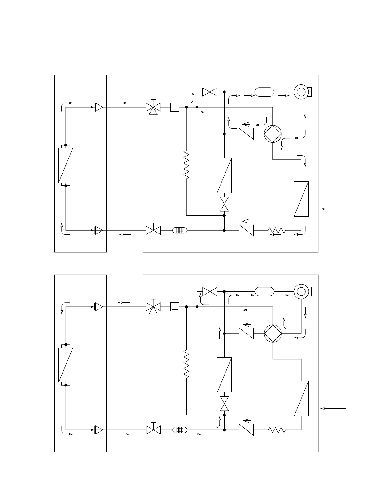
4. REFRIGERANT FLOW DIAGRAM
4-1. Refrigerant Flow Diagram
Indoor unit KGS1411 Outdoor unit CG1411
( )
( )
Indoor unit
Wide tube
Muffler
Wide tube
service valve
Reversing
valve
Check
valve 2
Check
valve 1
ON/OFF valve 2
ON/OFF
valve 1
Accumulator Compressor
Narrow tube
Narrow tube
service valve
Capillary tube
Capillary
tube
Strainer
O.D.
3/8" (9.52 mm)
O.D.
1/4" (6.35 mm)
Heat
exchanger
Heat
exchanger
Refrigerant
heater
HEATING CYCLE
Heating
cycle
Outdoor unit
( )
( )
Indoor unit
Wide tube
Muffler
Wide tube
service valve
Reversing
valve
Check
valve 2
Check
valve 1
ON/OFF valve 2
ON/OFF
valve 1
Accumulator Compressor
Narrow tube
Narrow tube
service valve
Capillary tube
Capillary
tube
Strainer
O.D.
3/8" (9.52 mm)
O.D.
1/4" (6.35 mm)
Heat
exchanger
Heat
exchanger
Refrigerant
heater
COOLING CYCLE
Cooling
cycle
Outdoor unit
Page 21

17
5. PERFORMANCE DATA
5-1. Performance Charts
Indoor unit KGS1411
Outdoor unit CG1411
● Cooling Characteristics ● Heating Characteristics
115 V
Indoor inlet air
D.B. temp. °F (°C)
12
11
10
9
8
7
6
5
70
(21.1)80(26.7)90(32.2)
100
(37.8)
110
(43.3)
120
(48.9)
Outdoor inlet air D.B. temp. °F (°C)
Operating current (A)
115 V
Indoor inlet air
D.B. temp. °F (°C)
12
11
10
9
8
7
6
5
20
(–6.6)30(–1.1)40(4.4)50(10.0)60(15.6)70(21.1)
Outdoor inlet air D.B. temp. °F (°C)
Operating current (A)
Outdoor inlet air D.B. temp. °F (°C)
(10.5)
(9.8)
(9.1)
(8.4)
(7.7)
(7.0)
(6.3)
(5.6)
(4.9)
(4.2)
(3.5)
Indoor inlet air
D.B. temp. °F (°C)
115 V
150
140
130
120
110
100
90
80
70
60
50
Low pressure psig (kg/cm
2
G)
at wide tube service valve
115 V
Outdoor inlet air D.B. temp. °F (°C)
(25.4)
(23.9)
(22.5)
(21.1)
(19.7)
(18.3)
(16.9)
(15.5)
(14.1)
(12.7)
(11.2)
360
340
320
300
280
260
240
220
200
180
160
Indoor inlet air
D.B. temp. °F (°C)
High pressure psig (kg/cm
2
G)
at wide tube service valve
10
(–12.2)
60
(15.6)
20
(–6.6)30(–1.1)40(4.4)50(10.0)60(15.6)70(21.1)
10
(–12.2)
70
(21.1)80(26.7)90(32.2)
100
(37.8)
110
(43.3)
120
(48.9)
60
(15.6)
80 (26.7)
70 (21.0)
59 (15.0)
80 (26.7)
70 (21.0)
59 (15.0)
90 (32.0)
80 (26.7)
70 (21.0)
90 (32.0)
80 (26.7)
70 (21.0)
● … Points of rating condition
Black dots in above charts indicate the following rating conditions.
Cooling: Indoor air temperature 80°F D.B. / 67°F W.B.
Outdoor air temperature 95°F D.B.
NOTE
Page 22

18
5-2. Air Throw Distance Charts
Indoor unit KGS1411
Room air temp.: 80°F (27°C)
Fan speed: High
Cooling
Room air temp.: 70°F (20°C)
Fan speed: High
Heating
5
5
10
Axis air velocity (ft./sec.)
Vertical distance (ft.)
Horizontal distance (ft.)
10 15
20 25 30
15
5
: Louver angle 0°
: Louver angle 30°
5
10 15
: Axis air velocity 0°
: Axis air velocity 30°
Horizontal distance (ft.)
20 25 30
10
Axis air velocity (ft./sec.)
Vertical distance (ft.)
15
: Flap angle 45°
: Flap angle 60°
: Axis air velocity 45°
: Axis air velocity 60°
Page 23

19
5-3. Cooling Capacity
Indoor unit KGS1411
Outdoor unit CG1411
115V single-phase 60Hz
TC : Total cooling capacity (BTU/h)
SHC : Sensible heat capacity (BTU/h)
CI : Compressor input (kW)
Rating conditions (# mark) are: Outdoor ambient temperature 95°F (35°C) D.B.
Indoor unit entering air temperature 80°F (26.7°C) D.B./67°F (19.4°C) W.B.
Rating Capacity: 9,000 BTU/h Air Flow Rate: 282 CFM
Evaporator Condenser
Ent. Temp. °F (°C) Ambient Temp. °F (°C)
WB DB
75 85 95 105 115
(23.9) (29.4) (35.0) (40.6) (46.1)
TC 9,120 8,680 8,170 7,610 6,980
CI 0.65 0.71 0.77 0.83 0.92
59 72 (22.2) SHC 6,750 6,530 6,280 6,010 5,710
(15.0) 76 (24.4) SHC 7,640 7,420 7,170 6,900 6,600
80 (26.7) SHC 8,570 8,350 8,100 7,610 6,980
84 (28.9) SHC 9,120 8,680 8,170 7,610 6,980
88 (31.1) SHC 9,120 8,680 8,170 7,610 6,980
TC 9,460 9,040 8,590 8,070 7,520
CI 0.65 0.72 0.78 0.85 0.94
63 72 (22.2) SHC 5,670 5,480 5,270 5,040 4,800
(17.2) 76 (24.4) SHC 6,560 6,360 6,160 5,930 5,690
80 (26.7) SHC 7,490 7,290 7,090 6,860 6,620
84 (28.9) SHC 8,370 8,180 7,980 7,750 7,510
88 (31.1) SHC 9,260 9,040 8,590 8,070 7,520
TC 9,820 9,430 # 9,000 8,520 8,000
CI 0.66 0.72 0.79 0.86 0.96
67 72 (22.2) SHC 4,580 4,420 4,240 4,050 3,840
(19.4) 76 (24.4) SHC 5,470 5,310 5,130 4,930 4,720
80 (26.7) SHC 6,400 6,240 6,060 5,860 5,650
84 (28.9) SHC 7,290 7,120 6,950 6,750 6,540
88 (31.1) SHC 8,180 8,010 7,830 7,640 7,430
TC 10,340 9,980 9,590 9,170 8,700
CI 0.67 0.73 0.8 0.88 0.98
71 72 (22.2) SHC 3,500 3,360 3,220 3,060 2,890
(21.7) 76 (24.4) SHC 4,390 4,250 4,100 3,950 3,770
80 (26.7) SHC 5,320 5,180 5,030 4,880 4,700
84 (28.9) SHC 6,210 6,070 5,920 5,760 5,590
88 (31.1) SHC 7,090 6,960 6,810 6,650 6,480
TC 10,550 10,210 9,850 9,430 8,990
CI 0.68 0.74 0.81 0.9 1
75 76 (24.4) SHC 3,230 3,110 2,990 2,850 2,700
(23.9) 80 (26.7) SHC 4,160 4,040 3,920 3,780 3,630
84 (28.9) SHC 5,050 4,930 4,810 4,660 4,520
88 (31.1) SHC 5,930 5,820 5,690 5,550 5,410
Page 24

20
5-4. Heating Capacity
Indoor unit KGS1411
Outdoor unit CG1411
20 30 40
47
50 60
Outdoor temperature °F (°C) D.B.
0
10
20
30
40
50
60
70
80
90
100
110
120
Heating capacity ratio %
100
(–9.4) (–1.1) (4.4)
(8.3)
(10.0) (15.5)
(–12.2)(–17.8)
1) ● … Point of rating condition
Black dot in the chart indicates the following rating condition.
Indoor: 70°F (21.1°C) D.B.
Outdoor: 47°F (8.3°C) D.B. / 43°F (6.1°C) W.B.
2) Above characteristics indicate instantaneous operation, which does not take into account defrost
operation.
3) Fan speed: High
4) Conventional heat pump type air conditioner may not generate enough heating capacity especially when
the outdoor temperature falls to extremely low level. Gas heater air conditioner can operate powerfully to
warm the room continuously even when the outdoor temperature becomes very low.
NOTE
Page 25

21
6. ELECTRICAL DATA
6-1. Electrical Characteristics
Indoor unit KGS1411
Outdoor unit CG1411
Indoor Unit Outdoor Unit Complete Unit
Fan Motor Fan Motor Compressor
Performance at 115V Single phase 60Hz
Rating conditions Running amp. A 0.35 0.64 7.2 8.2
Power input kW 0.033 0.077 0.79 0.90
Full load conditions Running amp. A 0.35 0.64 9.0 10.0
Power input kW 0.033 0.077 0.99 1.10
Rating conditions: Indoor air temperature 80°F (26.7°C) D.B. / 67°F (19.4°C) W.B.
Outdoor air temperature 95°F (35°C) D.B.
Full load conditions: Indoor air temperature 95°F (35°C) D.B. / 70°F (21.2°C) W.B.
Outdoor air temperature 115°F (46.1°C) D.B.
Rating conditions: Indoor air temperature 70°F (21.1°C) D.B.
Outdoor air temperature 47°F (8.3°C) D.B. / 43°F (6.1°C) W.B.
Full load conditions: Indoor air temperature 80°F (26.7°C) D.B.
Outdoor air temperature 75°F (23.9°C) D.B. / 65°F (18.3°C) W.B.
Indoor Unit Outdoor Unit Complete Unit
Fan Motor Fan Motor Compressor
Performance at 115V Single phase 60Hz
Rating conditions Running amp. A 0.35 0.64 4.9 5.9
Power input kW 0.033 0.077 0.51 0.62
Full load conditions Running amp. A 0.35 0.64 5.8 6.8
Power input kW 0.033 0.077 0.61 0.72
Heating
Cooling
Page 26

22
6-2. Electric Wiring Diagrams
(1) Indoor unit KGS1411
WARNING
To avoid electrical shock hazard, be sure to
disconnect power before checking, servicing
and/or cleaning any electrical parts.
1
2
3
4
5
6
7
8
1
2
121
2
131
3
121
2
3
1
2
3
1
2
3
1
3
5
1
3
5
4
5
1
2
3
4
5
1
2
3
4
5
1
2
3
4
5
1
2
3
4
5
6
7
8
123456789
10 11
123456789
10 11
1
2
3
4
5
6
7
8
1
2
3
4
5
6
7
8
1
2
3
4
G
Fan motor
G
P
S
FM
Connector
Flap motor
Flap
5P (GRN)
Hole IC
3P (WHT)
DC-CONT 11P (WHT)
DC-CONT 11P (WHT)
Power relay
AC out
Coil
2P (WHT)
Lamp
8P (WHT)
Fan
5P (WHT)
Trans 2
2P (RED)
RV
COM
Trans 1
3P (WHT)
Coil thermistor
FLP
WHT
PNK
BRN
BLU
Controller (A)
Controller (B)
BLK
GRY
Lamp (WHT)
IND LAMP ASSY
GRY
GRY
WHT
GRY
GRY
GRY
WHT
BRN
BRN
Power transformer
Terminal base (4P)
WHT
WHT
COM
CM ON
AC115V
RV ON
GND
WHT
BLU
BLK
To outdoor unit
RED
BLK
BLU
BLU
BLU
GRN
YEL
BLK
RED
BLU
3
4
Page 27

23
(2) Outdoor unit CG1411
WARNING
To avoid electrical shock hazard, be sure to
disconnect power before checking, servicing
and/or cleaning any electrical parts.
Reversing
valve
Combustion
motor
ON/OFF
Valve 1
ON/OFF
Valve 2
Ignition
transformer
Gas
valve 1
Gas
valve 2
Fan motor
Terminal
block
(BLU)
CN02
(GRN)
CN05
D
(BLK)
CN04
E
(BLK)
CN15
(GRY)
CN06
F
(RED)
CN07
G
(RED)
CN16
(WHT)
CN09
I
(WHT)
CN08
(WHT)
CN01
(WHT)
CN12
(WHT)
CN10A
(WHT)
CN10B
(WHT)
CN11
(WHT)
CN14
(YEL)
CN03
Power relay (K07)
Flame rod
Bimetal
thermostat
Power
transformer
Proportional
control valve
Thermal fuse
Thermistor 2
Thermistor 1
Compressor
Overload
protector
Start
relay
PNK
WHT
BLK
CN19
LD5
LD4
LD3
LD2
LD1
IC9
ICI
SWI
BRN
BLU
BRN
BLK
BLK
BLU
BLU
BLU
BLU
YEL
YEL
BLU
BLU
WHT
WHT
WHT
WHT
WHT
RED
RED
RED
RED
WHT
BLK BLK
PNK
BLK
BLK
BLK
BLK
ORG
ORG
ORG
ORG
WHT
WHT
VR1 VR2
FOI
C
B
FM
BLK
BLK
SV
GV1
GV2
PUR
PUR
BM
BLK
BLK
RV1
BLK
BLK
RV2
RED
RED
IG
H
J
P
Q1
Q2
N
0
K
M
CN17
W
R
R
S
PV
12345
6
C
CM
V
Page 28

24
(3) Printed circuit board POW-CG1411
K04
C101
K06
K03
K01
CN08
D11
CN06 CN07 CN09
D09
CN04CN05
F01
Z01
FUSE 250V/5A
FL
GND
J37
C09
C01
K07
K02
D10
D14
D16
D12
Q04
TR1
R60
D13
R72
R70
R09
L01
R07
R10
R84
R37
R36
R35
R34
R33
LD1
LD5
R78
R23
Q07
R30
R102
R100
R101
R46
R54
OSC
R51
C104
R25
R65R66
R52
R81
R17
R16
–
+
VR2
HIGH
R104
R19
R18
R103
R15
R29
Q03
R80
Q05
R28
R32
R68
R67
R20
R14
R12
R73
R74 R75
R76
R79
R50
D07
R26
R27
R24
R40
R59
R82
R22
D05
D01
CN17
D04
D17
IC9
IC8
C13
C29
R21
J11
IC1
RA1
J20
J22
J32
J33
R69
REG1
R71
R48
R106
R13
J19
J21
J24
J23
J25
J26
R31
C102
C10
C20
J09
J08
J07
J27
J28
J29
J30
IC3
SD1
IC2
IC5
IC7
PC2
PC1
PC3
IC6
+
+
_
13
CN10B
CN11CN14
D03
13
CN12
12
CN10A
14
CN03
CN01
CN19
13
CN02
13
R06
ABS1
R04
R03
R02
R01
K05
D15
J36
Z02
R105
J18
C05
C06
C24L03
C07
C03
C27
C02
C04
Q02
HS2
HS1
J16
J15
J06
J04
J05
J35
J34
J01
J02
SW1
C28
C11
C16
C14
C21
C105
C100
D02
SD2
SD3
+
–
+
–
+
–
+
–
J17
C14
C15
CN15CN16
CN21
C32
R53
C25
C22
R63
R57
R83
R47
R49
R64
C18
C17
R39
R41
R38
R56
R55
C31
C12
C08
C19
L02
–
+
VR1
LO
J14
Q06
C33
J13
J03
J12
C26
D06
D100
D08
J10
R58
J31
C103
LO/HIGH
LD4
LD3
LD2
98
4FF4B10002710-2
TD-T13VXX
Page 29

25
7. INSTALLATION INSTRUCTIONS
7-1. Installation Site Selection
7-1-1. Indoor Unit
AVOID:
● direct sunlight.
● nearby heat sources that may affect performance of
the unit.
● areas where leakage of flammable gas may be
expected.
● places where large amounts of oil mist exist.
DO:
● select an appropriate position from which every cor-
ner of the room can be uniformly cooled. (High on a
wall is best.)
● select a location that will hold the weight of the unit.
● select a location where tubing and drain hose have
the shortest run to the outside.
● allow room for operation and maintenance as well as
unrestricted air flow around the unit. (Fig. 1)
● install the unit within the maximum elevation differ-
ence (H) above the outdoor unit and within a total
tubing length (L) from the outdoor unit as detailed in
Table 1 and Fig. 2.
Table 1
2"(5 cm)
min.
2"(5 cm)
min.
2"(5 cm) min.
Front View
Fig. 1
INDOOR
UNIT
Tubing length (L)
OUTDOOR
UNIT
Elevation
difference (H)
Fig. 2
WARNING
To prevent abnormal heat
generation and the possibility
of fire, do not place obstacles, enclosures and grilles
in front of or surrounding the
air conditioner in a way that
may block air flow.
Indoor unit
Floor level
Wall
Minimum height
from floor level
5 ft. (1.5 m)
Fig. 3
For stable operation of
the air conditioner, do not
install wall-mounted type
indoor units under 5 ft.
(1.5 m) from floor level.
CAUTION
Max. Allowable Tubing Min. Allowable Tubing Limit of Tubing Limit of Elevation Required Amount of
Model Length at Shipment Length at Shipment Length (L) Difference (H) Additional Refrigerant
ft. (m) ft. (m) ft. (m) ft. (m) oz./ft. (g/m)*
CG1411 25 (7.5) 13 (4) 49 (15) 23 (7) 0.27 (15)
* If total tubing length becomes 25 to 49 ft. (7.5 to 15 m) (max.), charge additional refrigerant (R22) by 0.27 oz./ft. (15 g/m).
No additional compressor oil is necessary.
Page 30

26
7-1-2. Outdoor Unit
AVOID:
● heat sources, exhaust fans, etc. (Fig. 4)
● damp, humid or uneven locations.
DO:
● choose a place as cool as possible.
● choose a place that is well ventilated.
● allow enough room around the unit for air intake/
exhaust and possible maintenance. (Fig. 5a)
Outdoor unit
Hot air
Heat source
Exhaust fan
NO
Fig. 4
CAUTION
● Install the outdoor unit above snowfall line.
● Do not place objects on or sit on the outdoor
unit. Also, never block the air intake/outlet or
exhaust. Distortion of the outdoor unit or
incomplete combustion may result.
● Touching the air exhaust can cause a burn.
Take special care for children not to touch it.
● Do not introduce foreign matter into the air
intake/outlet or exhaust. Do not insert pointed objects, such as sticks.
● When the ambient temperature is dropping, a
white cloud or fog may be seen blowing from
the unit. This does not indicate a problem.
● The distance between any building opening*
and the exhaust must be 24 in. (60 cm) or
more.
● Locate the outdoor unit away from windows
to avoid possible entry of exhaust gases into
the building. Pay special attention to the windows of a neighboring house or building.
● If there is a window within 24 in. (60 cm) of
the exhaust, make sure it is not located
inside the projected exhaust area within
24 in. (60 cm) above, within 6 in. (15 cm)
below, within 6 in. (15 cm) on either side, or
within 6 in. (15 cm) in front of the exhaust.
* Meaning of “building opening”
Windows or doors which can be opened, but not
including those which are fixed or cannot be
opened.
Air intake Min. 6" (15 cm)
Air discharge
Min. 6"
(15 cm)
Min. 12"
(30 cm)
Valve side
Min. 10"
(25 cm)
Min.
7 ft.
(2 m)
Min.
7 ft.
(2 m)
Min. 6 in.
(15 cm)
Air intake
Ground
Obstacle
Obstacle above
Air discharge
Fig. 5a
Page 31

27
● provide a solid base (level concrete pad, concrete
block, 4 in. × 16 in. (10 × 40 cm) beams or equal),
a minimum of 4 in. (10 cm) above ground level to
reduce humidity and protect unit against possible
water damage and decreased service life (Fig. 5b).
● use lug bolts or equal to bolt down unit, reducing
vibration and noise.
● use only the type of gas indicated on the name-
plate. This plate is located on the right side of the
outdoor unit, and should be checked before gas
line connection.
Min. 4" (10 cm)
Anchor bolts
(4 pcs.)
Exhaust
guard
Exhaust
port
Screws
Fig. 5b
7-2. Recommended Wire Length and Diameter
Regulations on wiring diameter differ from locality to locality. For field wiring requirements, please refer to your
local electrical codes. Carefully observe these regulations when carrying out the installation.
Refer to the wiring system diagram (Fig. 6).
Refer to your local codes or in the absence of local codes with the National Electric Code: ANSI/NFPA70.
NOTE
1
2
3
4
1
2
3
4
5
GG
G
6
INDOOR UNIT
TERMINAL (4P) TERMINAL (6P)
OUTDOOR UNIT
(INTER UNIT)
Power line
115V
Grounding line
Grounding line
Disconnect switch
(Field supply)
L1
Power supply:
Single-phase 60 Hz
115 VAC
L2
Fig. 6
CAUTION
● Be sure to connect the power supply line to the
outdoor unit as shown in the wiring diagram. The
indoor unit draws its power from the outdoor
unit.
WIRING SYSTEM DIAGRAM
WARNING
● Be sure to comply with local codes on running
wiring from the outdoor unit to the indoor unit
(size of wire and wiring method, etc.).
● Each wire must be firmly connected.
● No wire should be allowed to touch refrigerant
tubing, the compressor, or any moving part.
● To avoid the risk of electric shock, each air
conditioner unit must be grounded.
WARNING
Page 32

28
7-3-1. Mounting on a Wall
a) Removable mounting
1) Momentarily hold the remote control unit at the desired
mounting position.
2) Confirm that the air conditioner responds correctly when you
press keys on the remote control from that position.
3) After confirming correct operation, use a screwdriver to screw
the supplied special mounting screw into the wall. (Fig. 7)
4) Hang the remote control unit from the special mounting
screw.
b) Non-removable mounting
1) Momentarily hold the remote control unit at the desired
mounting position.
2) Confirm that the air conditioner responds correctly when you
press keys on the remote control from that position.
3) After confirming correct operation, use a screwdriver to screw
the mounting screw into the wall. (Fig. 7)
4) Remove the remote control cover by sliding it downward.
5) Remove the batteries of the remote control unit.
6) Use a screwdriver to screw the remote control unit securing
screw into the wall through the hole in the battery compartment. (Fig. 8)
7) Replace the batteries.
8) Again confirm that the remote control unit operates correctly.
Wall
Screw
(Packed in indoor unit)
Fig. 8
Wall
Special
mounting
screw
(Packed in indoor unit)
Fig. 7
Removable mounting
Non-removable mounting
7-3. Remote Control Unit Installation Position
The remote control unit can be operated from either a non-fixed position or a wall-mounted position.
To ensure that the air conditioner operates correctly, do not install the remote control unit in the following places:
● In direct sunlight
● Behind a curtain or other place where it is covered
● More than 26 ft. (8 m) away from the air conditioner
● In the path of the air conditioner’s airstream
● Where it may become extremely hot or cold
● Where it may be subject to electrical or magnetic interference
Page 33

29
8. FUNCTION
8-1. Motion Explanation
8-1-1. Heating
Heating operation begins with the refrigerant pump down cycle to move refrigerant into the heating circuit of the
system. Simultaneously, gas burner ignition is initiated for a period of about 1 minute.
When the refrigerant transport period is completed, refrigerant is contained within the heating circuit tubing and
retained there by the 2 check valves. The refrigerant pump down circuit condition is established by the reversing
valve set to the heating position and the ON/OFF valve, V1, is closed.
Upon completion of the pump down phase, the ON/OFF valve is opened for normal heating operation.
Cooling heat transfer tubing in the outdoor section is blocked from refrigerant flow by check valves during the
heating cycle.
Heating circuit refrigerant tubing is in contact with the exterior wall of the aluminum heat exchanger above the gas
burner. Heated refrigerant is circulated from the outdoor heat exchanger tubing to the indoor heat transfer tubing
by operation of the compressor. Controls maintain refrigerant temperature to a point above the saturation temperature and so the temperature is circulated as a gas.
Refrigerant flow is through the ON/OFF valve, V2, under stable conditions to provide for low power operation.
Low power operation is initiated (V2 opens) when thermistor-1 senses the temperature of equalization at 263 psig
(18.5 kg/cm2).
8-1-2. Cooling
Identical to operation for a typical ductless split air conditioner (heat pump).
● Indoor Unit
Room temperature sensor
Outdoor heat exchanger
Capillary tube Outdoor fan
outdoor fan motor
Thermal
fuse
Bimetal
thermostat
Proportional
control valve
Refrigerant
Heater
Solenoid
valve 2
Solenoid
valve 1
Manual
shut-off
valve
Gas inlet
Exhaust chimney
Check valve 1 Thermistor 2
V1 (ON/OFF valve)
V2 (ON/OFF valve)
Check
valve 2
Accumulator
Combustion
blower motor
Combustion
blower fan
Compressor
Reversing
valve
Fan
Indoor
heat
exchanger
Coil temperature sensor
Inter-unit cable
Wide tube
Thermistor 1
Narrow tube
HeatingCooling
● Outdoor Unit
Page 34

30
8-1-3. Combustion Control
(1) Combustion
Combustion air is supplied into the burner for 20 seconds prior to ignition. The variable speed combustion air
blower motor speed is sensed and controlled. After this pre-purge is competed, spark ignition is provided at the
burner. Burner condition is monitored continuously during the burning period.
(2) Safety Controls
Following safety devices function to control the gas solenoid valve to shut off
● Flame Detection Circuit: Stops gas flow with flame sensor circuit
● Bimetal Thermostat: Stops gas flow with bimetal thermostat at 221°F (105°C)
● Thermal Fuse: Stops gas flow with thermal fuse at 302°F (150°C) — replaceable fuse
● Fuse-Control Circuit: Protected by internal 3A and 5A device
Exhaust
Refrigerant
heater
Supply
Gas inlet
Joint
Solenoid
valve 1
Solenoid
valve 2
Combination
gas valve
Flame sensor
probe
Ignition
electrical rod
Air
Combustion
blower fan
Ignition
circuit
Timer circuit
Pre-purge circuit
Combustion
blower motor
Flame sensor
circuit
Power
supply
Page 35

31
8-2. Cooling
8-2-1. Room Temperature Control
● Room temperature control is obtained by cycling the compressor ON and OFF under control of the room
temperature sensor in the indoor unit.
● All information is transmitted every 3 minutes by the remote control unit to the controller in the indoor unit.
● The control circuit will not attempt to turn the compressor ON until the compressor has been OFF for at
least 3 minutes. To protect the compressor from stalling out when trying to start against the high side
refrigerant pressure, the control circuit has a built-in automatic time delay to allow the internal pressure to
equalize.
● As a protective measure, the control circuit switches the compressor OFF after 3 minutes or more of com-
pressor operation.
● Thermo. ON: When the room temperature is above T°F (T°F is set temperature).
Compressor ➔ ON
● Thermo. OFF: When the room temperature is equal to or below set temperature T – 1°F.
Compressor ➔ OFF
3 minutes 3 minutes 3 minutes
Set temp.
T°F
T – 1°F
Compressor
More than
3 minutes
Set speed
OFF OFF
OFF OFF
Outdoor fan
Indoor fan
Thermo.
OFF
Thermo.
ON
Thermo.
OFF
Thermo.
ON
Page 36

32
8-2-2. Freeze Prevention (Cooling)
● This function prevents freezing of the indoor heat exchange coil.
● When the compressor has been running for 6 minutes or more and the temperature of the indoor heat
exchange coil falls below 36°F (2.4°C), the control circuit stops the compressor for at least 6 minutes. The
compressor does not start again until the temperature rises above 46°F (8°C) or 6 minutes have elapsed.
6 minutes
Set temp.
46°F
36°F
Compressor
Indoor heat exch.
coil temp.
Indoor fan
More than
3 minutes
More than
3 minutes
More than
10 minutes
Set speed
Page 37

33
8-3. Heating
8-3-1. Room Temperature Control
● Room temperature control is obtained by cycling the compressor ON and OFF under control of the room
temperature sensor in the indoor unit.
● All information is transmitted every 3 minutes by the remote control unit to the controller in the indoor unit.
● The control circuit will not attempt to turn the compressor ON until the compressor has been OFF for at
least 3 minutes. To protect the compressor from stalling out when trying to start against the high side
refrigerant pressure, the control circuit has a built-in automatic time delay to allow the internal pressure to
equalize.
● As a protective measure, the control circuit switches the compressor OFF after 3 minutes or more of com-
pressor operation.
● Thermo. ON: When the room temperature is below T + 1°F (T°F is set temperature).
Compressor ➔ ON
● Thermo. OFF: When the room temperature is equal to or below set temperature T + 2°F.
Compressor ➔ OFF
3 minutes 3 minutes
Thermo.
OFF
Thermo.
ON
Thermo.
OFF
Thermo.
ON
OFF
OFF
OFF
OFF
OFF
OFF
OFF OFF
OFF
Set temp.
T+2°F
T+1°F
113°F
(45°C)
90°F
(32°C)
Compressor
Indoor fan
Combustion
Indoor heat exch.
coil temp.
Operation button
More than
3 minutes
More than
3 minutes
LL LL
Reversing
valve coil
30
sec.
30
sec.
Set speed
Set
speed
Page 38

34
8-3-2. Refrigerant Control
(1) Thermistor 1
1) Initial check:
Must be able to confirm temperature increase of 2°F (1°C) within approximately 1 minute.
Objectives: 1. To detect error in switching reversing valve
2. To detect disconnection of Thermistor 1
2) Limit on amount of combustion at low temperature:
When starting up at low temperature, this function prevents rapid increase in temperature of refrigerant.
1. Minimum combustion at 50°F (10°C) or below
2. Limits combustion up to 70% of the maximum rated power at 95°F (35°C) or below
3) Bypass valve operation:
Opens the bypass valve at 117°F (47°C) and reduces power consumption.
4) Limit on amount of combustion at high load:
● Limits amount of combustion at 144°F (62°C)
Resets when temperature decreases to 140°F (60°C).
● Stops combustion at 149°F (65°C)
Resets when the temperature decreases to 131°F (55°C). (Compressor continuously operates.)
Error stop occurs after combustion stops eight times. (Operation lamp on indoor unit blinks.)
(2) Thermistor 2
1) Limit on amount of combustion:
Limits combustion when temperature exceeds 131°F (55°C). The range is proportionally controlled
between the minimum and maximum temperatures.
2) Combustion stop:
Stops combustion when temperature exceeds 185°F (85°C).
Error stop occurs after combustion is interrupted (stops) eight times. (Operation lamp on indoor unit
blinks.)
3) Detection of bypass valve operation
Must be able confirm temperature increases 5°F (3°C) within approximately 1 minute.
Page 39

35
8-3-3. Combustion Saving Function
After Thermo. OFF occurs, shifts to Continuous Combustion Mode, Save Mode 1, or Save Mode 2, according to
the load inside the room.
<Normal Combustion Mode>
Performs combustion which is proportionally controlled by setting the maximum amount of gas equivalent
to the amount of rated combustion.
<Save Mode 1>
Performs combustion which is proportionally controlled by setting the maximum amount of gas to about
70% of the rated amount of combustion.
<Save Mode 2>
Performs continuous combustion by setting the amount of gas equivalent to the minimum amount of combustion.
(1) Save Function
If Thermo. ON lasts less than 10 minutes under Normal Combustion Mode subsequent to Thermo. OFF, Save
Mode 1 is automatically selected for the following Thermo. ON, and then Save Mode 2 is selected if Save Mode 1
lasts less than 10 minutes.
(2) Reset Function
When combustion in Save Mode 1 continues past 10 minutes, it goes back to Normal Combustion Mode (Save
Mode 2 to Save Mode 1). However, if Thermo. OFF occurs again within 10 minutes under Normal Combustion
Mode, Save Mode 1 is selected at the next Thermo. ON (Save Mode 1 to Save Mode 2).
Normal Combustion
Mode
Save Mode 1
Thermo.
OFF
Less than
10 minutes
Less than
10 minutes
Less than
10 minutes
Thermo.
OFF
Thermo.
OFF
Thermo.
OFF
Save Mode 2
Stop combustion
Normal Combustion
Mode
Save Mode 1
Save Mode 2
Thermo.
OFF
Thermo.
OFF
10 minutes 10 minutes 10 minutesLess than
10 minutes
Page 40

36
8-3-4. Cold Draft Prevention Function (During Heating Operation)
This function prevents a cold draft from being released at the beginning of Heating Operation or during operation
of the room temperature thermo.
Change in Fan Speed
● When Heating Operation is started with the temperature of the heat exchanger less than 90°F (32°C):
● Until the temperature of the heat exchanger goes over 117°F (47°C), fan speed varies according to the
temperature of the heat exchanger.
● Once the temperature of the heat exchanger rises over 117°F (47°C), cold draft prevention function is
released.
Temperature of
coil temperature sensor
Fan speed
Set speed
LL
117°F (47°C)
90°F (32°C)
Temperature of
Less than 90°F (32°C) 90 – 117°F (32 – 47°C) Over 117°F (47°C)
heat exchanger
Fan speed LL LL – Set speed Set speed
Page 41

37
8-4. Fan Speed Control
During Cooling Operation Automatic fan speed
TS + 4°F (2°C)
3 minutes
OFF
T
S
+ 2°F (1°C)
Set Value (T
S
)
H
M
L
ON
OFF
Fan Speed
Compressor
3 minutes
ON
TR:
Room temp.
TS – 2°F (1°C)
Ts
T
S
+ 2°F (1°C)
30 seconds 30 seconds
H
M
LL
Compressor ON
Compressor OFF
Fan Speed
TR:
Room temp.
* For 3 minutes after power ON, the compressor does not turn on.
* For 30 seconds after the compressor is turned OFF, the previous fan speed is maintained.
During Heating Operation Automatic fan speed
Page 42

38
8-5. Dry Operation (Dehumidification)
● Dry operation uses the ability of the cooling cycle to remove moisture from the air, but by running at low
level to dehumidify without greatly reducing the room temperature. The air conditioner repeats the cycle of
turning ON and OFF automatically as shown in the chart below according to the room temperature.
● Intermittent ventilation occurs by switching the indoor fan speed between L ↔ LL.
● Dry operation does not occur when the room temperature is under 59°F (15°C), which is the Monitor
Zone.
● When the compressor stops, the indoor fan stops as well.
NOTE
Room temp.
T + 4°F (2°C)
T – 2°F (1°C)
Room temp.
59°F (15°C)
Set temp. T°C
Cooling operation
* Dry A Zone
Compressor: Continuous operation
FMI (indoor fan): L (low speed)/LL (very low speed) intermittent ventilation only while the compressor is ON.
* Dry B Zone
Compressor: Intermittent operation (ON for 3 minutes and OFF for 9 minutes)
FMI (indoor fan): L (low speed)/LL (very low speed) intermittent ventilation only while the compressor is ON.
Monitor Zone
Both the indoor and outdoor units stop.
Page 43

39
8-6. Automatic Operation
(1) Normal
● Set temperature can be shifted ± 4°F (2°C), in 2°F (1°C) steps.
● If operation commences again within 2 hours of the previous operation, the previous setting is applied.
(2) Changing fan speed “Automatic”
Fan speed is automatically selected by the temperature difference between the room temperature (TR) and set
temperature (TS).
During Heating Operation
During Cooling Operation
Room temperature at start of operation Temperature set automatically Operation mode
TR°F (°C) °F (°C)
88 (30) ≤ T
R
82 (27)
84 (24) ≤ TR < 88 (30) 80 (26) Cooling
80 (26) ≤ TR < 84 (28) 78 (25)
72 (22) ≤ TR < 80 (26) 76 (24) Dry
TR < 72 (22) 76 (24) Heating
Room temperature (TR) and set temperature (TS) Fan speed
TR≥ TS+ 4°F (2°C) H / High
TS+ 4°F (2°C) > TR≥ TS+ 2°F (1°C) M / Medium
TS+ 2°F (1°C) ≥ TR≥ T
S
L / Low
TS> TR(Thermo. OFF) L / Low
Room temperature (TR) and set temperature (TS) Fan speed
TR≤ T
S
H / High
TS< TR< TS+ 2°F (1°C) M / Medium
TS+ 2°F (1°C) ≤ TR(Thermo. OFF) LL / Very Low
Page 44

40
8-7. Freeze Prevention
When the evaporation temperature drops to less than the temperatures stated below during Cooling or Dry
Operation, the operation of the outdoor unit is automatically stopped to prevent the heat exchanger from
freezing up.
(1) Cooling / Dry Cooling Zone: Dry A Zone
< Conditions of freeze prevention operation >
a. Temperature of heat exchanger is less than 36°F (2.4°C)
b. During Cooling or Dry Operation When the conditions of a, b, and c are met
c. More than 6 minutes pass after start of operation
< Conditions of Reset >
When temperature of heat exchanger rises to 46°F (8°C) or more.
(2) Dry B Zone
< Conditions of freeze prevention operation >
a. Temperature of heat exchanger is less than 36°F (2.4°C)
b. During Dry Operation
When both conditions a and b are met
< Conditions of Reset >
When temperature of heat exchanger rises to 46°F (8°C) or more.
* During freeze prevention operation, the indoor fan stops (Dry B Zone only).
Page 45

41
8-8. Overload Prevention (Heating)
8-8-1. Indoor Unit
● This function prevents overheating of the indoor heat exchange coil.
● When the temperature of the indoor heat exchange coil rises above 131°F (55°C), and if the indoor fan is
L (low speed), then the fan speed changes from L (low speed) to M (medium speed).
8-8-2. Outdoor Unit
● Unless the temperature of Thermistor 1 drops to 144°F (62 °C) or less from the point A within 1 minute,
The burner is set to M (point C.)
● Reset is activated when the temperature of Thermistor 1 drops to 122°F (50°C) or less, with the burner
being set to H.
● High-load protection for the outdoor unit is operated independently from the high-load protection for the
indoor unit.
Compressor
Indoor fan
Indoor heat
exch.coil
temp.
H→H, M→M, L→M
131°F
(55°C)
113°F
(45°C)
H or M or L
ON
Thermistor 1
149°F
(65°C)
144°F
(62°C)
122°F
(50°C)
Combustion
Compressor
H
M
L
C
A
B
H
1 minute
Stop
Page 46

9. OPERATION FLOWCHARTS
9-1. Cooling, Dry
9-1-1. Star ting Flowchart
Cool • Dry
Operation starts
Room temp. higher
than preset temp.
Coil thermistor
(higher than 46°F)
Operation lamp light ON
Dry
Cooling
Indoor fan: Start speed ON
NO
YES
NO
NO
NO
YES
YES
YES
YES
Troubleshoot
Operation starts
Overload relay works
1
2
Flap motor ON
Outdoor fan motor OFF
Compressor OFF
Compressor OFF
Outdoor fan motor OFF
Outdoor fan motor OFF
Flap motor OFF
Indoor fan OFF
Indoor power relay OFF
Outdoor power relay ON
Outdoor fan motor ON
Compressor ON
All lamps Light OFF
Compressor OFF
Coil thermistor
(higher than 36°F)
3 min. timer
count-up
YES
Cooling
Safety device works
18
Dry
19
Room temp. ≥ Preset
+2
Indoor fan
Outdoor fan motor ON
Compressor
NO
YES
Room temp. ≥ Preset
+2
Outdoor fan motor
ON
Compressor
YES
Room temp. ≥ 15°C
Monitor
Indoor fan
Outdoor fan motor OFF
Compressor
Outdoor fan motor
Compressor
3 min. ON
9 min. OFF
Intermittent
Indoor fan
Low &
very low
Indoor fan
Low &
very low
Dry A Dry B
9-1-2. Stopping Flowchart
Operation starts
Operation lamp Light OFF
Compressor OFF
Indoor fan OFF
Outdoor fan OFF
9-1-3. Check Refrigerant Cycle Flowchart
YES
Intake-outlet
temp. lower than
14 to 18°F
Current
(8.5A)
Obstructed heat exchanger
Over-charge of
refrigerant
Cooling operation
Refrigerant shortage
Troubleshoot
Capillary tube blockage
Cooling
NO
YES
YES
Pressure at
service port
(86 to 128psi)
NO
NO
Normal
Compressor failure
9-1-4. Time Flowchart
ON timer
Cool
Stop dry
Heat
Cool
Dry
Heat
NO
YES
Timer passes
Remote control unit
OFF timer set
Timer lamp Light ON
Timer lamp Light OFF
Operation lamp Light OFF
OFF timer
Cool
Dry
Heat
NO
YES
Timer passes
Remote control unit
OFF timer set
Timer lamp Light ON
Timer lamp Light OFF
42
Page 47

Combustion lamp flashes
Wire misconnection
Amp. current is high
Amp. current is low
Initial
check 1 normal
Power Supply
Troubleshoot
Operation starts
Operation stops
1
2
3
4
3
6
8
7
7
Flap motor
E
2
P ROM read fail
Coil temp thermistor fail
Operation lamp flashes
Room temp thermostat fail
Combustion lamp flashes
Indoor fan
ON
NO
YES
NO
NO
NO
NO
YES
YES
YES
YES
ON LL
Operation lamp light
Reversing valve
ON
ON
Compressor ON
Initial
check 2 normal
Gas
combination valve &
circuit normal
Room temp.
(lower than set temp.)
9
9
a
Combustion motor (0 or 40 sec. after)
(80 sec. after)
(3 sec. after)
(more than 19A 2 sec. after)
(more than 17A 8 sec. after)
ON
10
11
12
Proportional control valve
ON
13
Solenoid valve GV1 ON14Solenoid valve GV2 ON
Solenoid valve GV1
OFF
Solenoid valve GV2
OFF
15
Ignitor ON
Combustion lamp ON
Indoor fan OFF
Compressor OFF
Solenoid valve GV1
OFF
Solenoid valve GV2
OFF
Proportional control valve OFF
Combustion lamp OFF
Ignitor OFF
Ignitor OFF
16
2
ON/OFF valve ON
ON/OFF valve 2 ON
Fan speed: Set speed
17
11
8
17
b
c
8
Fan speed: Set speed
Proportional controlled
combustion
3 min. timer
count-up
NO
YES
Initial check 3
normal
NO
YES
Thermistor 1, 2
normal
Operation lamp light
OFF
Indoor fan OFF
Flap motor
Compressor
Reversing valve
Operation lamp
OFF
Lamp flashes
OFF
OFF
ON/OFF valve V2
ON/OFF valve V1
(3 sec. after from )
OFF
Combustion motor
OFF
valve PV
Proportional control
OFF
Solenoid valve GV1
OFF
Solenoid valve GV1
(60 sec. after)
OFF
Solenoid valve GV2
OFF
valve PV
Proportional control
OFF
OFF
LD 2345
LD 2345
LD 2345
NO
NO
LD 2345
NO
NO
YES
YES
YES
Combustion motor
rev. normal
Flame sensor
circuit normal
11
NO
YES
Detect flame
(higher than 1µA)
NO
YES
Indoor coil temp.
(lower than 32°C)
NO
YES
(30 sec. after)
Thermistor-1
(higher than 47°C)
NO
YES
Safety device works
NO
YES
Room temp.
(higher than set temp.)
NO
YES
Thermistor-1
(higher than 42°C)
Flame sensor failure
: light off
NO
YES
First
Thermal fuse bimetal
thermostat normal
NO
YES
First
Combustion lamp flashes
LD 2345
LD 2345
LD 2345
C
(12 sec. after)
(15 sec. after)
(3 sec. after
from )
a
NO
YES
Combustion
continues more than
4 min.
LD 2345
LD 2345
LD 2345
LD 2345
Thermistor-1
higher than (185°F 85°C)
Thermistor-2
higher than (149°F 65°C)
Combustion lamp OFF
Combustion motor
(60 sec. after)
OFF Combustion motor
(60 sec. after)
OFF
Solenoid valve GV2
OFF
Solenoid valve GV1
OFF
Proportional control
valve PV
OFF
c
ON/OFF valve failure
Solenoid valve GV2
OFF
Solenoid valve GV1
OFF
Proportional control
valve PV
OFF
5
LD 2345
Combustion motor
(60 sec. after)
OFF
c
Reversing valve failure
Solenoid valve GV2
OFF
Solenoid valve GV1
OFF
Proportional control
valve PV
OFF
4
Combustion motor
(60 sec. after)
OFF
Solenoid valve GV2
OFF
Solenoid valve GV1
OFF
Proportional control
valve PV
OFF
NO
YES
Less than 3 times
NO
YES
Thermistor-1
(lower than 122°F 50°C)
NO
YES
NO
YES
Thermistor-2
(lower than 131°F 55°C)
10 min. passes
from
b
17
LD 2345
Combustion motor
(60 sec. after)
OFF
c
Solenoid valve GV2
OFF
Solenoid valve GV1
OFF
Proportional control
valve PV
OFF
Combustion lamp OFF
Thermistor-1
higher than (149°F 68°C)
Thermal fuse
bimetal thermostat failure
ON/OFF valve V2
ON/OFF valve V1
(3 sec. after from )
OFF
OFF
C
ON/OFF valve V2
ON/OFF valve V1
(3 sec. after from )
OFF
OFF
Compressor
Reversing valve
OFF
OFF
C
Combustion motor
(60 sec. after)
OFF
Solenoid valve GV2
OFF
Solenoid valve GV1
OFF
Proportional control
valve PV
OFF
Combustion lamp OFF
: light on
9-2. Heating
9-2-1. Star ting Flowchart
43
9-2-2. Stopping Flowchart
Operation starts
Operation lamp Light OFF
Operation lamp Light OFF
Compressor OFF
Indoor fan OFF
Solenoid valve GV1 OFF
Solenoid valve GV2 OFF
Proportional control valve OFF
On/Off valve V1 OFF
On/Off valve V2 OFF
Reversing valve OFF
Combustion motor OFF
(180 sec.
after)
(60 sec.
after)
Page 48

44
10. PROCEDURE FOR DISMANTLING THE UNIT
10-1. Procedure for Dismantling the Indoor Unit
(1) How to remove grille
(2) How to remove PCBs
➀ Close the flap (upper airflow adjustment plate)
and open the screw covers. Then remove the
screws (2).
➂ Detach the attachment tabs (2) at the top of the
grille by lifting the grille.
➁ Remove the fixing tabs (3) at the bottom of
decorative grille.
Detach all the wire connectors on PCB A and B in the electrical component box, and remove the tabs
holding the PCBs. Detach the PCBs A and B from the top.
Page 49

45
(3) How to remove electrical component box
➀ Remove the screw for ground screw (green, 1).
(4) How to remove drain pan
Remove the screw (1) attaching the drain pan and remove it upward by pressing the tabs (one each for
right and left) hooked to the frame.
➂ Remove the screws (3) attaching the electrical
component box, and remove the box from the
frame by pressing the tabs at the back of the
box.
➁ Remove the connectors for sensor, fan motor
and flap motor, which are connected to the
electrical component box.
Page 50

46
(5) How to detach heat exchanger
➀ Remove the screws (2) attaching the metal clip
of the tube. Extend the supplementary tubing at
the back of the unit.
➁ Remove the screws (3) attaching the heat
exchanger. Remove the tabs holding the resin
boss at the top right of the heat exchanger, and
then pull the heat exchanger off from the
frame.
(6) How to detach fan and fan motor
➀ Loosen the hexagonal screw in the fan boss
which attaches the fan.
➁ Remove the screw (1) for the fan bearing
cover.
➂ Pull out the fan boss from the fan motor shaft,
and then pull out the fan to the left.
➃ Remove the fan motor by picking it up.
Page 51

47
10-2. Procedure for Dismantling the Outdoor Unit
(1) How to remove the external panels
(2) How to detach the rear panel
➀ Remove the screws (2) of the top panel and
the screws (5) of the front panel.
➁ Remove the screw (1) of the side cover, the
screws (3) of the terminal block cover, and the
screws (2) of the terminal block.
➀ Remove the front panel and unscrew the
screws (9) attaching the rear panel, and detach
the manual shut-off valve.
(3) How to detach the combustion blower
➀ Remove the screws (2) attaching the blower. ➁ Detach CN5 and CN14 on outdoor unit PCB.
Page 52

48
(4) How to detach combination valve and gas conduit
➀ Remove the screw (1) for the attachment plate of the combination valve in back of the main unit.
➁ Detach the 2 connectors (CN11 for proportional valve and CN08 for solenoid valve).
➂ Remove the screws (2) attaching the gas conduit in front of the combustion chamber, and take off the
combination valve with gas conduit.
(5) How to detach combination valve
➀ Remove the attachment screws, and dismantle as shown below.
➂
Page 53

49
(6) How to detach ignition probe and flame sensor electrode
➀ Detach the connector of the ignition probe.
➁ Remove connector CN17 from outdoor unit PCB.
➂ Remove the screw (1) for the attaching metal clip and remove the ignition probe and flame sensor elec-
trode. (Flame sensor electrode is replaced together with the wires connected.)
(7) How to detach burner unit
➀ Remove the attachment screws (6) and pull the burner unit to the front. (When reattaching the burner unit,
replace the center screw first.)
(8) How to detach gas nozzle
➀ Remove burner unit.
➁ Remove the screws (2) attaching the nozzle.
(Rear view)
Page 54

50
11. POINTS TO DIAGNOSE
11-1. Indoor Unit Alarm Signal
11-2. Manifold Pressure
● To set manifold pressure there are 2 settings – low pressure and high pressure.
● Use SW1 to move to the 2 modes used to adjust the two pressures.
Press SW1 1 time for low pressure.
Press SW1 2 times for high pressure.
Press SW1 3 times for normal operation.
● Use VR1 to set the low, lighting pressure and VR2 to set the high pressure.
● Step 1: Set low pressure
1. Press SW1 and hold until LEDs 4 and 5 flash.
2. Adjust the low pressure with VR1 to 0.63 inches of water column.
● Step 2: Set high pressure
1. Press SW1 again and LEDs 1 and 2 will flash.
2. Adjust pressure with VR2 to 3.43 inches of water column.
● Step 3: Set lighting pressure
Lighting pressure will be set automatically from Step 1 and Step 2.
Check these settings 2 or 3 times to insure all are correct then reset until no LEDs flash.
NOTE
Alarm Signal Error Meaning Operation Information
Misconnection of inter-unit wiring Heating • Cooling • Dry Connect correctly
Room temp. thermistor is defective Heating • Cooling • Dry Normal: 9 – 11 kΩ at 50°F
4 – 6 kΩ at 77°F
Power Lamp Heat exch. thermistor is defective Heating • Cooling • Dry Normal: 100 – 120 kΩ at 50°F
Flashing 50 – 60 kΩ at 77°F
Fan motor is defective Heating • Cooling • Dry Alarm signal appears in 1 min.
Amp. current is high Heating • Cooling • Dry More than 17 amp.
Amp. current is low Heating • Cooling • Dry Less than 0.8 amp.
Heat exch. thermistor detects high temp Heating More than 154°F (68°C)
Outdoor Unit Fuel Inlet Pressure W.C. (kPa) Manifold Pressure W.C. (kPa)
Low High Lighting (10 sec.)
LD4, 5 Flashing LD2, 3 Flashing (verification)
CG1411 Natural gas 7.0 (1.74) 0.63 (0.157) 3.43 (0.853) 2.32 (0.579)
Page 55

51
11-3. Checking Electrical Components
11-3-1. Components
Flow Measurement Target (Normal) Upper: Volt, Amp.
Remarks
No. CO. No. Wire Color (Normal) Lower: Resistance
1 T WHT – BLU
DC 1 – 12 (Pulse)
Flap motor
300 – 450 Ω
BLU – BRN
AC 100 – 130 V
2 S
30 – 60 Ω
Indoor fan motor
RED – BLU
DC 1 – 12V
More than 3000 Pulse/min.
50°F (10°C) 9.0 – 11.0 kΩ
Indoor
3 Z 1WHT – GRY2 68°F (20°C) 5.5 – 7.0 kΩ
86°F (30°C) 3.5 – 4.5 kΩ
room temperature sensor
4 U 3BLK – BLK4
50°F (10°C) 100 – 120 kΩ Indoor
68°F (20°C) 50 – 60 kΩ coil temperature sensor
5 B BLK – BLK
AC 100 – 130 V
Reversing valve
300 – 400 Ω
BLK – WHT
6 R WHT – PNK 1 – 5 Ω Compressor
BLK – PNK
7 Terminal block WHT 3 – 5 A Ampere current
68°F (20°C) 9.8 – 10.8 KΩ
Outdoor
8 KM BLK – BLK 86°F (30°C) 6.8 – 7.3 KΩ
140°F (60°C) 2.4 – 2.6 KΩ
thermistor 1, 2
D PUR – PUR
AC 30 – 115 V
Combustion blower motor
9
10 – 30 Ω
N RED – BLU
DC 1 – 5 V Combustion blower motor
More than 1000 Pulse/min. fan speed sensor
! O BLU – BLU
DC 5 – 24 V Proportional
40 – 160 Ω control valve
" J BLK – Ground
AC 100 – 130 V
Flame sensor probe
More than DC 1 µA
# P YEL – YEL
Not more than DC 1 V Thermal fuse
Not more than 1 Ω bimetal thermostat
$ I WHT – WHT
DC 90 – 120 V
Gas valve 1
1 – 2.5 kΩ
% I ORG – ORG
DC 90 – 120 V
Gas valve 2
1 – 2.5 kΩ
& G RED – RED AC 100 – 130 V Ignition transformer
( E BLK – BLK
AC 100 – 130 V
ON/OFF valve 1
300 – 500 Ω
) F BLK – BLK
AC 100 – 130 V
ON/OFF valve 2
300 – 500 Ω
C WHT – BLU AC 100 – 130 V
~
V
WHT – BRN 70 – 150 Ω Outdoor fan motor
WHT – PNK 300 – 500 Ω
+ W PNK – PNK
Not more than AC 1 V
Overload relay
Not more than 1 Ω
Operation
Outdoor Unit Voltage at Terminal Block
1 – 21– 31– 4
Cooling • Dry 100 – 130 V 100 – 130 V 0 V
Heating 100 – 130 V 100 – 130 V 100 – 130 V
OFF 0 V 100 – 130 V 0 V
Page 56

52
11-3-2. Indoor Unit
Indoor Unit
Transformer Voltage • Coil Resistance
Measurement Target (Normal) Upper: Voltage
CN Wire Color (Normal) Lower: Resistance
Y
1 WHT – WHT
AC 100 – 130 V
45 – 100 Ω
Y
2 BRN – BRN
AC 12 – 18 V
0.5 – 4 Ω
11-3-3. Outdoor Unit
Outdoor Unit
Transformer Voltage • Coil Resistance
Measurement Target (Normal) Upper: Voltage
CN Wire Color (Normal) Lower: Resistance
H ORG – ORG
AC 100 – 130 V
50 – 100 Ω
Q
2 YEL – YEL
AC 100 – 130 V
0.5 – 4 Ω
Q
1 RED – RED
AC 20 – 30 V
1 – 10 Ω
Q
1 BLU – BLU
AC 10 – 15 V
5 – 15 Ω
Page 57

53
12. TROUBLESHOOTING
12-1. Check Before and After Troubleshooting
12-1-1. Check Power Supply Wiring
● Check that power supply wires are correctly connected to Terminals L and N on the terminal plate in the
outdoor unit.
12-1-2. Check Inter-Unit Wiring
● Check that inter-unit wiring is correctly connected to the outdoor unit from the indoor unit.
12-1-3. Check Power Supply
● Check that voltage is in specified range (±10% of the rating).
● Check that power is being supplied.
12-1-4. Check Lead Wires and Connectors in Indoor and Outdoor Units
● Check that coating of wires is not damaged.
● Check that lead wires and connectors are firmly connected.
● Check that wiring is correct.
INDOOR UNIT
Terminal (4P) Terminal (6P)
(Inter-unit)
Power line
115V
OUTDOOR UNIT
1
2
3
4
GG
1
2
3
4
G
5
L1
Power supply
Single-phase 60 Hz
115 VAC
L2
Grounding line
6
Grounding line
Disconnect switch
(Field supply)
Page 58

54
12-2. When the Air Conditioner Does Not Work at All (Both Indoor and
Outdoor Units) — Operation Lamp Does Not Light
12-2-1. Malfunction in Power Supply
➀ Check if operation selector of the indoor unit is set to ON. If it is not, set the switch to ON.
➁ Check if the circuit breaker is disengaged or if electricity is not being supplied properly.
Normal AC 104 – 126 V
In case of abnormality ➞ Check power source
No abnormalities, proceed to 12-2-2.
* Use a circuit tester (set to AC range).
12-2-2. Abnormalities in Power Transformer
➀Check voltage on the secondary core side.
Measure voltage 2P connector of TRANS 2 (without disconnecting connectors).
Caution: Care should be taken that the tips of the tester rods do not touch each other since the circuit is
electrically charged.
In case of abnormality ➞ Replace the power transformer.
Normal TRANS 2 BRN – BRN AC 12 – 18 V
*Use a circuit tester (set to AC range).
12-3. Operation Lamp Blinks (It Keeps Blinking after 3 Minutes Following
Start of Operation)
If the operation lamp continues to blink more than 3 minutes, check for the following possible causes in this order:
(1) Incorrect Wiring of Inter-unit Wiring (connector No. 1 – 4)
(2) Thermistor Abnormality (Indoor Unit Only)
(3) Protective Circuit of Outdoor (Burner) Unit Operated (during heating operation only)
(4) CT Detection
(5) Indoor Fan is Defective
(6) Power Circuit Wiring Error
(7) Outdoor Unit Power Supply Failure
(8) Outdoor Unit Power Transformer Defective
(9) Outdoor Unit Compressor Motor Overload Relay Has Operated
(10)Outdoor Unit Compressor Motor Defective
12-3-1. Incorrect Wiring of Inter-unit Wiring
If the blinking of the operation lamp occurs upon initial operation following installation work, incorrect wiring of
inter-unit cable between indoor and outdoor units is likely. Correctly rewire the inter-unit cable.
Caution: Be sure to turn off the circuit breaker switch before carrying out the wiring work.
Page 59

55
No. Caused by (outdoor unit)
LED lamps
Meaning
2 3 4 5
— Normal ●● ●● ●● ●● Normal operation
— Defective in IC chip (E2PROM) ●● ●● ●● ● Cannot read IC chip data or missing IC chip on outside
PCB
— Defective Gas Valves ●● ●● ● ●● Detects abnormality in Gas Valve Circuit at initial
checking
A Detective Thermistor 1 ●● ●● ●● Open or Short of Thermistor 1
B Detective Thermistor 2 ●● ● ●● ●● Open or Short of Thermistor 2
C Limit switch ●● ● ●● ● Thermal fuse or Bimetal Thermostat tripped
D Flame current circuit ●● ● ● ●● Defective abnormal in Flame Current Circuit
E Lighting failure ●● ● ● ● Couldn’t establish flame
F Lost flame ● ●● ●● ●● Flame Sensor Circuit detects lost flame and could not
establish the flame
G Incorrect combustion motor speed ● ●● ●● ● Incorrect combustion motor speed
H Over-time period in retry ● ●● ● ●● Thermistor 1 or Thermistor 2 temperature did not go
down in set period
I Over number of times in retry ● ●● ●● Combustion stopped by Thermistor 1 or Thermistor 2
more than set number
J Bypass Valve (V2) not open ● ● ●● ●● Bypass Valve failure or drop-out of Thermistor 2
— Reversing Valve not working ● ● ●● ● Reversing Valve failure, drop-out of Thermistor 2, or
shortage of refrigerant
12-3-2. Thermistor Abnormality (Indoor Unit Only)
Check open / short circuit at the coil thermistor and room thermistor (between 1 and 2 of the lamp 8P) on the
PCB of the indoor unit (but only when the room temperature is 14 to 113°F).
12-3-3. Protective Circuit of Outdoor (Burner) Unit Operated
Check the following according to the failure display. Check items listed in 12-6. Heating Operation Not Possible.
12-3-4. CT Detection (Refer to 12-3-9 and 12-3-10.)
(1) Compressor abnormality
(2) Compressor over-load relay engaged
Note: Refer to 12-8. Failure Display on Outdoor Unit and Correction Method.
●● light off
● light on
Page 60

56
12-3-5. Indoor Fan is Defective
➀Check if the indoor fan is locked up.
Turn fan gently by hand.
➁Check if motor circuit is defective.
Set temperature by remote controller so that air conditioner operates under Thermo. OFF in either cooling or
heating operation, then start operation.
Check if it operates without the operation lamp blinking for more than 3 minutes.
When fan does not turn easily ➞ Replace fan motor
No abnormalities, proceed to check ➁.
In case of abnormality (operation lump starts blinking after about 1 minute) ➞ Proceed to check ➂.
No abnormalities, proceed to check ➂.
➂Check indoor unit PCB.
Measure voltage between 1 – 2 of 3P connector (Hole IC) on indoor unit PCB.
Caution: Care should be taken that the tips of the tester rods do not touch each other since the circuit is
electrically charged.
➃Disconnect FAN 5P connector on indoor unit PCB and measure resistance between cables.
In case of abnormality ➞ Replace indoor unit PCB.
No abnormalities, proceed to check ➃.
In case of abnormality ➞ Replace the indoor fan motor.
No abnormalities, replace indoor unit PCB.
Normal
Connector No. Voltage
Between 1 – 2 DC 3 – 7 V
Color Resistance
Normal BLU – BRN 94 – 116 Ω
BLU – PNK 115 – 141 Ω
*Use a circuit tester (set to DC range).
12-3-6. Power Circuit Wiring Error
Check wiring of power circuit.
Set temperature by remote controller so air conditioner operates under Thermo. ON in cooling operation, then
start operation.
Check if compressor motor operates for more than 10 seconds.
It does not operate at all ➞ Proceed to check 12-3-7 and 12-3-8.
Stops operation in about 3 seconds ➞ Proceed to check 12-3-9.
No abnormalities, proceed to check 12-4.
Page 61

57
12-3-7. Outdoor Unit Power Supply Failure
Measure voltage between Terminals 5 – 6 on terminal block of outdoor unit.
Set temperature by remote controller so conditioner operates under Thermo. ON in either cooling or heating
operation, then start operation. Then measure voltage between Terminals 1 – 2 on terminal block of outdoor
unit.
Caution: It is not possible to measure while 3-minute restart timer is in operation.
In case of abnormality ➞ Check connection of inter-unit cable.
No abnormalities, replace indoor unit PCB.
No abnormalities, proceed to check 12-3-8.
* Use a circuit tester (set to AC range).
Normal AC 104 – 126 V
12-3-8. Outdoor Unit Power Transformer Defective
➀Check voltage of power transformer.
Measure voltage of 4P connector (CN10A), 3P connector (CN10B) and 2P connector (CN09) of indoor unit
PCB (without disconnecting connectors).
Caution: Care should be taken that the tips of the tester rods do not touch each other since the circuit is
electrically charged.
In case of abnormality ➞ Replace power transformer.
No abnormalities, replace outdoor unit PCB.
4P, CN10A
RED – RED 20 – 30 V
Normal
BLU – BLU 10 – 15 V
3P, CN10B YEL – YEL 85 – 115 V
CN09 ORG – ORG 104 – 126 V
*Use a circuit tester (set to AC range).
In case of abnormality ➞ Check it again after more than 30 minutes (wait for it to cool down). If the result is
the same, replace the temperature overload relay.
No abnormalities, check wiring to overload relay.
12-3-9. Outdoor Unit Compressor Motor Overload Relay Has Operated
Caution: Carry out this check only after cutting power at the mains or disconnecting unit from the power
supply.
➀Check temperature overload relay for continuity.
Normal 1 Ω or less
* Use a circuit tester (set to Ω range).
Page 62

58
12-3-10. Outdoor Unit Compressor Motor Defective
➀Check if compressor motor is locked up.
Set temperature by remote controller so air conditioner operates under Thermo. ON in cooling operation, then
start operation.
Check if compressor operates.
➁Measure resistance of compressor motor.
Disconnect each wire from the top of the compressor and measure resistance of each phase.
No abnormalities, proceed to check ➁.
In case of abnormality ➞ Stops in 2 to 5 seconds. Humming of compressor motor can be heard.
After auto restart by 3-minute timer, same thing happens. If this condition continues, replace the compressor motor.
Caution: Carry out this check only after cutting power at the mains or disconnecting unit from the power
supply.
In case of abnormality ➞ Replace compressor.
Phase Resistance
Normal
R – S 1 – 5 Ω
S – C 1 – 5 Ω
C – R 1 – 5 Ω
* Use a circuit tester (set to Ω range).
12-4. Outdoor Unit Fan Does Not Work
12-4-1. Outdoor Unit Fan Motor Defective
➀Check if outdoor unit fan is locked up.
Turn fan gently by hand.
When fan does not turn easily ➞ Replace fan motor.
No abnormalities, proceed to check ➁.
*Use a circuit tester (set to Ω range).
➁Measure resistance between each wire.
In case of abnormality ➞ Replace fan motor.
No abnormalities, check continuity of each wire (PNK, BRN and BLU).
Color Resistance
Normal BLU – BRN 70 – 150 Ω
BLU – PNK 300 – 500 Ω
Page 63

59
12-5. Flap Motor Does Not Work
12-5-1. Louver Motor Defective
➀Set to cooling operation with flap to oscillate (movie) using remote controller and measure voltage applied to
the louver motor at FLAP terminal of 5P connector.
In case of abnormality ➞ Replace indoor unit PCB.
No abnormalities, proceed to check ➁.
*Use a circuit tester (set to DC range).
Normal
Color Output Voltage
WHT and each BLU wire DC 1 – 12 V (pulse)
*Use a circuit tester (set to Ω range).
Normal
Color Resistance
WHT and each BLU wire 300 – 450 Ω
➁Disconnect FLAP of 5P connector for louver motor and measure resistance.
In case of abnormality ➞ Replace louver motor.
No abnormalities, check if there is physical or mechanical interference to louver movement.
12-6. Heating Operation Not Possible
12-6-1. Thermistor 1 Defective
Failure Display on Outdoor Unit PCB: ●● ●● ●●
Check Thermistor 1 (CN15).
➀Disconnect Thermistor 1 connector (3P, BLK) from outdoor unit PCB, and measure resistance on Thermistor 1
side.
In case of abnormality ➞ Replace Thermistor 1.
Temperature Resistance
Normal
68°F (20°C) 6.0 – 7.1 kΩ
86°F (30°C) 4.0 – 5.0 kΩ
140°F (60°C) 1.5 – 1.7 kΩ
Temperature Resistance
Normal
68°F (20°C) 6.0 – 7.1 kΩ
86°F (30°C) 4.0 – 5.0 kΩ
140°F (60°C) 1.5 – 1.7 kΩ
12-6-2. Thermistor 2 Defective
Failure Display on Outdoor Unit PCB: ●● ● ●● ●●
Check Thermistor 2 (CN16).
➀Remove Thermistor 2 connector (3P, RED) from the outdoor unit PCB, and measure resistance on the
Thermistor 2 side.
In case of abnormality ➞ Replace Thermistor 2.
Page 64

60
12-6-3. Safety Device Operated
Failure Display on Outdoor Unit PCB: ●● ● ●● ●
Check safety device.
➀Disconnect safety device connector (CN12, 2P, WHT) from outdoor unit PCB, and measure resistance on the
safety device.
In case of abnormality ➞ Replace temperature fuse or temperature limiting switch.
Normal 1 Ω or less
*Use a circuit tester (set to Ω range).
In case of abnormality ➞ Replace outdoor unit PCB.
In case of abnormality ➞ Replace outdoor PCB.
➁Remove flame rod connector, and measure direct current between connector and PCB.
Caution: The flame rod retains electromotive force immediately after combustion ceases, therefore measure-
ment should be made while the equipment is cool.
12-6-4. Erroneous Flame Detection
Failure Display on Outdoor Unit PCB: ●● ● ● ●●
Check flame sensor probe.
➀Measure voltage of alternative current between flame rod connector (1P, CN17) and ground.
Normal AC 104 – 126 V
Normal DC 1µA or less
*Use a circuit tester (set to AC range).
*Use a circuit tester (set to DC range).
Normal AC 104 – 126 V
12-6-5. Ignition Failure
Failure Display on Outdoor Unit PCB: ●● ● ● ●
1) Check ignition transformer.
➀Check if ignition wires are disconnected or have voltage leak.
➁Measure AC voltage between the connectors (CN07) to the ignition electrode.
In case of abnormality ➞ Replace outdoor unit PCB.
If voltage is normal but sparking noise cannot be heard, replace the ignition electrode.
Caution: If the ignition wires are disconnected, connect them by pushing them in firmly.
2) Check gas valve (GV1).
➀Measure DC voltage at the connector (CN08) of electromagnetic valve (under heating operation, during com-
bustion).
In case of abnormality ➞ Replace outdoor unit PCB.
Normal WHT – WHT DC 90 – 120 V
*Use a circuit tester (set to AC range).
*Use a circuit tester (set to DC range).
Page 65

61
Normal ORG – ORG DC 90 – 120 V
Normal WHT – WHT 1 – 2.5 kΩ
Normal ORG – ORG 1 – 2.5 kΩ
In case of abnormality ➞ Replace heating electromagnetic valve.
➁Disconnect heating gas valve (GV1, CN08) connector, and measure resistance at connector.
In case of abnormality ➞ Replace outdoor unit PCB.
3) Check electromagnetic valve (GV2) of the combination gas valve.
➀Measure DC voltage at electromagnetic valve connector (CN08) (under heating operation, during combustion).
In case of abnormality ➞ Replace heating electromagnetic valve.
➁Disconnect heating electromagnetic valve connector (CN08), and measure resistance at connector.
Normal AC 104 – 126 V
In case of abnormality ➞ Replace outdoor unit PCB.
4) Check proportional control valve (PV).
➀Measure DC voltage at proportional valve connector (CN11) (under heating operation, during combustion).
In case of abnormality ➞ Replace flame rod.
5) Check flame rod.
➀Check if flame rod connector (CN17, 1P) is connected properly.
➁Measure AC voltage between flame rod connector and ground.
*Use a circuit tester (set to Ω range).
*Use a circuit tester (set to Ω range).
Normal BLU – BLU DC 5 – 30 V
*Use a circuit tester (set to DC range).
*Use a circuit tester (set to AC range).
*Use a circuit tester (set to DC range).
In case of abnormality ➞ Replace flame rod.
➂Disconnect flame rod connector (CN17) and measure direct current at connector.
Normal DC 2µA or more
*Use a circuit tester (set to DC range).
12-6-6. Erroneous Flame-Out Condition
Failure Display on Outdoor Unit PCB: ● ●● ●● ●●
➀Check in same manner as “Failure Display ●● ● ● ●.”
Page 66

62
12-6-7. Combustion Blower Motor Abnormal Revolution
Failure Display on Outdoor Unit PCB: ● ●● ●● ●
Check combustion blower motor.
➀Measure AC voltage at blower motor connector (CN05) (under heating operation, during combustion).
In case of abnormality ➞ Replace outdoor unit PCB.
In case of abnormality ➞ Replace combustion blower motor.
➁Disconnect combustion blower motor connector, and measure resistance at connector.
*Use a circuit tester (set to AC range).
*Use a circuit tester (set to Ω range).
Normal PUR – PUR AC 30 – 115 V
*Use a circuit tester (set to AC range).
Normal BLK – BLK AC 104 – 126 V
*Use a circuit tester (set to AC range).
Normal BLK – BLK AC 104 – 125 V
Normal BLK – BLK 300 – 500 Ω
Normal BLK – BLK 300 – 500 Ω
Normal PUR – PUR 10 – 30 Ω
12-6-8. ON/OFF Valve Failure
Failure Display on Outdoor Unit PCB: ● ● ●● ●●
Check ON/OFF valve coil (CN06).
➀Measure AC voltage at the ON/OFF valve coil connector (under heating operation, during combustion).
In case of abnormality ➞ Replace outdoor unit PCB.
In case of abnormality ➞ Replace ON/OFF valve coil.
➁Disconnect ON/OFF valve connector and measure resistance at connector.
*Use a circuit tester (set to Ω range).
12-6-9. Reversing Valve Failure
Failure Display on Outdoor Unit PCB: ● ● ●● ●
Check reversing valve coil.
➀Measure AC voltage at reversing valve coil connector (CN03) (under heating operation, during combustion).
In case of abnormality ➞ Replace outdoor unit PCB.
In case of abnormality ➞ Replace reversing valve coil.
➁Disconnect reversing valve coil connector and measure resistance at connector.
Caution: Reversing valve failure can be displayed when there is a shortage of refrigerant. Therefore if the
above check shows normal, check the amount of refrigerant.
*Use a circuit tester (set to Ω range).
Page 67

63
12-7. Reset Method When Error Occurs During Heating Operation
Wait for 4 minutes or more after the power is on, and then press the operation button on the remote control unit.
Page 68

12-8. Failure Display on Outdoor Unit and Correction Method
No. Caused by (outdoor unit) LED lamps
Meaning
Error Detected Points to Diagnose Correction Methods
2 3 4 5
— Normal ●● ●● ●● ●● Normal operation — — —
— Defect in IC chip (E
2
PROM) ●● ●● ●● ●
— Defective Gas Valves ●● ●● ● ●●
A Defective Thermistor 1 ●● ●● ●●
B Defective Thermistor 2 ●● ● ●● ●●
C Limit switch ●● ● ●● ●
D Flame Current Circuit ●● ●●●●
E Lighting failure ●● ●●●
F Lost flame ● ●● ●● ●●
G Incorrect combustion motor speed ● ●● ●● ●
H Over-time period in retry ● ●● ● ●●
I Over number of times in retry ● ●● ●●
J Bypass Valve (V2) not open ●●●● ●●
— Reversing Valve not working ●●●● ●
Gas switching IC (EEP-ROM) data was not
read properly by microcomputer upon
power-on
Electricity applied to GV1 / GV2 while gas
valve is closed
Open / short circuit of Thermistor 1
Open / short circuit of Thermistor 2
Temperature fuse / temperature limiting
switch operated
Flame current detected while combination
gas valve is closed
Fail to ignite by ignition operation (including
retry)
Extinction after flame detection, and does
not re-try (burning after re-try, yet extinguishes within 4 minutes)
Inadequate revolution speed
➀At ignition:
Does not reach 500rpm within 20 seconds
Reaches 500rpm within 20 seconds yet
does not reach prescribed revolutions
(approx. 1,850rpm) within 60 seconds
➁Less than 500rpm (other than ignition)
Thermistor 1 and/or Thermistor 2 do not
cool down to normal temperature within 10
minutes after being heated up to a specified temperature (gas is cut off when overheating)
Fourth overheating is detected. Retry is
performed up to 3 times when Thermistor 1
and / or Thermistor 2 cool down to normal
temperature within 10 minutes
Thermistor 2 does not detect temperature
increase (approx. xx°F (2°C)) within 30 seconds after ON/OFF valve (RV2) is ON
Thermistor 1 fails to detect temperature
increase (approx. xx°F (1°C)) within 30 seconds after ON/OFF valve (V1) is open at
ignition operation
Can not read IC chip data or missing IC chip on outside PCB
Detect abnormality in Gas Valve
Circuit at initial checking
Open or Short of Thermistor 1
Open or Short of Thermistor 2
Thermal fuse or Bimetal Thermostat
tripped
Abnormality in Flame Current
Circuit
Could not establish flame
Flame Sensor Circuit detects lost
flame and could not establish the
flame
Incorrect combustion motor speed
Thermistor 1 or Thermistor 2 temperature did not go down during set
period
Combustion stopped by Ther mistor
1 or Thermistor 2 more than set
number
Bypass Valve failure or drop-out of
Thermistor 2
Reversing Valve failure, drop-out of
Thermistor 2, or shortage of refr igerant
● Confir m proper inser tion of gas switching
IC, then reset power supply
● Measure voltage of GV1 (WHT – WHT of I)
and GV2 (ORG – ORG of I) (normal value:
DC0V)
● Measure resistance of Thermistor 1 (BLK –
BLK of M.) (normal value: 6.6±0.5 kΩ at
68°F (20°C))
● Measure resistance of Thermistor 2 (BLK –
BLK of K.) (normal value: 6.6±0.5 kΩ at
68°F (20°C))
● Check continuity of temperature fuse and
temperature limiting switch (YEL – YEL of
P) (normal value: 1Ω or less)
● Measure electric current between BLK of
flame rod and CN17(J) on the PCB (normal value: 0 µA, combination gas valve
closed)
● Measure electric current between BLK of
flame rod and CN17(J) on the PCB (normal value: 3 µA or more at ignition)
● Check positioning of ignition plug, flame
rod and burner (normal: electric discharge
gap approx. 4mm)
● Confir m sparking noise at the igniter
As above
● Check revolution of combustion blower fan
● Measure voltage of combustion blower
motor (PLE – PLE of D) (normal value: AC
30 – 115 V)
● Check for refrigerant leaks (pressure in
wide tube while cooling operation: approx.
85.0 PSIG (6 kgf/cm
2
)
As above
● Check position of Thermistor 2.
● Measure voltage at ON/OFF valve (RV2)
(BLK – BLK of F) (normal value: AC 104 –
126 V, ON)
● Check for refrigerant leakage
● Check position of Thermistor 1
● Measure voltage at reversing valve (BLK –
BLK of B) (normal value: AC 104 – 126 V,
ON)
➀ Replace gas switching IC chip
➁ Replace outdoor unit PCB
➀ Replace outdoor unit PCB
➀Check / modify Connector CN 15 (M)
➁ Replace Thermistor 1
➂ Replace outdoor unit PCB
➀Check / modify connector CN 16 (K)
➁ Replace Thermistor 2
➂ Replace outdoor unit PCB
➀Check / modify connector CN12 (P)
➁ Replace thermal fuse
➂Replace bimetal thermistor
➀Replace flame sensor probe (CN17)
➁ Replace outdoor unit PCB
➀Check / modify connector CN17 (J)
➁Check / modify connector CN7 (G)
➂Replace ignition electrode
➃Check / modify insertion of wire on secondar y
side of ignition transformer
➄Replace flame rod
➅Replace ignition transformer
➆
Replace outdoor unit PCB or power transformer
As above
➀Check / modify connector CN5 (D)
➁Check / modify connector CN14 (N)
➂Replace combustion blower fan motor set
➃Replace outdoor unit PCB
➀Repair refrigerant tubes (connections, etc.)
(leaks)
➁Charge additional refrigerant (leaks)
➂Replace units
As above
➀Confirm / modify position of Thermistor 2
➁Confirm / modify connector CN6 (F)
➂Replace ON/OFF valve 2 (coil)
➃Replace outdoor unit PCB
➄Replace units
➀Repair refrigerant tubes (connections, etc.)
(leaks)
➁Charge additional refrigerant (leaks)
➂Check / modify position of Thermistor 1
➃Check / modify connector CN03 (B)
➄Replace reversing valve (coil)
➅Replace outdoor unit PCB
Note: Failure display remains even after power reset following repairs.The display is overridden upon operation of compressor when heating operation is carried out for a second time after the repair.
64
Page 69

65
13. SPECIAL PRECAUTIONS WHEN SERVICING THE UNIT
Important!
For your personal safety, be sure to read and understand the following
precautions before servicing.
● To avoid risk of injury when servicing the outdoor unit (for instance, when replacing the compressor or repair-
ing a refrigerant leak), follow the procedure below for the refrigerant circuits of the outdoor unit.
PROCEDURE
13-1. BLK/WHT Connector Attachment for Servicing
13-1-1. Confirm mains power is switched OFF, then, detach the connectors (BLK and WHT) for the electromag-
netic valves, SV1 and SV2, from the terminals CN4 and CN6 on the PCB.
13-1-2. Connect the special connector (field supply) and the connector (BLK and WHT). Following this, re-apply
power at 115V and open the electromagnetic valves, SV1 and SV2.
13-1-3. Provide a disconnect switch to the special connector.
13-1-4. Turn the disconnect switch ON to supply power (single-phase, 115V) to the special connector. This
makes it possible to force open 2 solenoid valves (SV1 and SV2) in the refrigeration circuit outdoor unit.
(Fig. 3)
Injuries can occur from burns or inhalation of toxic gas if servicing is performed while refrigerant remains in the refrigeration circuit. This servicing
includes disassembling brazed tubing connections and removing any
refrigeration parts or components.
WARNING
Important!
The procedures given in “13-2” to “13-5” below must be carried out with the 2 solenoid valves SV1
and SV2 open.
Fig. 1
● Condition at shipping and operation ● Condition at servicing
Power supply
Black
CN4
CN6
AC115V
White
V2
V1
Connectors for servicing
Disconnect switch (Field supply)
Special
connector
Black
White
V2
Outdoor PCB
Outdoor PCB
CN4
CN6
V1
Page 70

13-2. Refrigerant Recovery
13-2-1. Open service valve to recover refrigerant into refrigerant
recovery unit.
13-3. Service on Outdoor Unit
13-3-1. After making sure that the refrigerant in the circuit has
been completely discharged, perform required servicing,
such as replacing the compressor or repairing refrigerant
leaks.
13-3-2. Before going on to the next step, leak test all joints where
welding has been done.
Nitrogen gas is best when pressurizing the system for a
leak test. However, if it is necessary to instead test with
refrigerant gas, be sure to recover all gas into the refrigerant recovery unit after completing the leak test.
13-4. Evacuation Using Vacuum Pump
13-4-1. Using a hex wrench, set the valve stems of the narrow
and wide tube service valves as indicated in the table
below.
Refer to Service Valve
Construction shown in Fig. 3.
NOTE
NOTE
Refrigerant released into the air contributes to
destruction of our planet’s ozone layer. You should
always use the refrigerant recovery unit to help
protect the environment.
CAUTION
Service Valve Valve Position
Narrow
Position – a –
Wide
Action
Narrow Tube Service
Valve (2-Way)
Wide Tube Service
Valve (3-way)
Fully OPEN
Position – a –
Position – b –
*
Hose
CLOSED
*
*
Fig. 2
Fig. 3
66
Outdoor unit
Pressure
gauge
Manifold valve
HiLo
Vacuum pump
Page 71

67
13-4-2. Connect the vacuum pump and a manifold valve as shown Fig. 1. Confirm that all connections are cor-
rectly made.
In order to withstand negative suction pressure during evacuation, the manifold valve should be
equipped with a Hi/Lo compound gauge with a minimum scale reading of –76 cmHg.
13-4-3. Install (first by hand-tightening, then securely with a wrench) flare nuts and bonnets at service valves in
the refrigeration circuit where evacuation will take place. This process is highly important to completely
evacuate the system.
13-4-4. Check that the BLK/WHT connector is properly attached. (Fig. 1)
13-4-5. Turn the disconnect switch ON (if it has been OFF) to open the 2 solenoid valves (SV1 and SV2). (Fig. 2)
13-4-6. With both the “Lo” and “Hi” knobs of the manifold valve open, run the vacuum pump. The operation time
varies with the capacity of the pump. (Run the pump at least 30 minutes.) Evacuation is successful if
the vacuum gauge reading remains at –75 cmHg or more for at least 10 seconds after closing both the
“Lo” and “Hi” knobs of the manifold valve.
13-4-7. With the vacuum pump still running, turn both the narrow and wide service valves all the way in to close
the valves (position – b – in Fig. 3). Then stop the pump.
13-4-8. After removing the vacuum hoses from the service valves, replace the flare nuts and bonnets on the
valves. The refrigerant circuit is now ready for charging.
13-5. Refrigerant Charging
13-5-1. After evacuation is completed, charge the circuit with the proper amount of refrigerant.
The proper amount of refrigerant is specified on the nameplate of the outdoor unit and in Section
“2-1. Unit Specifications” in the service manual.
13-5-2. Use a hose to connect the narrow tube service valve to the
liquid port of the charging cylinder. (Fig. 4)
13-5-3. Purge air from the hose. Do this by opening the charging
cylinder valve, then slightly loosening the connection to the
narrow tube service valve. Wait a few moments, then
retighten the connection.
13-5-4. With a hex wrench, open the service valve little by little to
let liquid refrigerant enter the circuit. (Fig. 4)
Write down the gradation levels on the charging cylinder
before and after the charging. This allows you to calculate
the charging volume.
NOTE
NOTE
NOTE
Charging
volume
Gradation
level before
charging
Gradation
level after
charging
= –
Outdoor unit
Charging cylinder
Open
Fig. 4
Page 72

68
13-5-5. If it is not possible to completely charge the unit with the proper amount of refrigerant, you can do an
additional charging after installing the units. At that time, refrigerant should be recharged in the liquid
state a little at a time using the wide tube service port, and the air conditioner should be operating in
COOLING mode during the entire charging process.
Charging the unit with a large amount of refrigerant at once may damage the compressor. Always
charge the unit at a constant charging rate of about 0.2 lb (100 g).
13-6. Reattaching BLK/WHT Connectors for Operation
13-6-1. Turn off the power source.
13-6-2. Connect the BLK/WHT connectors to each other as in the original state.
NOTE
Remember to reattach the BLK/WHT connectors in their original position. Otherwise, the system
will not operate correctly and damage may occur.
CAUTION
Page 73

1
INSTRUCTION MANUAL
KGS 1411 + CG1411
APPENDIX
Page 74

For Your Safety Read Before Operation
WARNING:
If you do not follow these instructions exactly, a fire or
explosion may result causing property damage,
personal injury or loss of life.
A. This appliance is supplied natural gas for heat
source into outdoor section.
Read the following safety information before
operation and/or maintenance is performed.
B. This appliance dose not have a pilot light. It is
equipped with an ignition device which
automatically lights the burner.
Do not try to light the burner by hand.
C. BEFORE OPERATING: Smell around the appliance
area for gas. Be sure to smell next to the floor
because some gas is heavier than air and will
settle on the floor.
WHAT TO DO IF YOU SMELL GAS
•
Do not try to light any appliances.
•
Do not touch any electric switch; do not use
any phone in your building.
•
Immediately call your gas supplier from a
neighbor’s phone.
Follow the gas supplier’s instructions.
•
If you reach your gas supplier, call the fire
department.
D. Use only your hand to push in or turn the gas
control knob. Never use tools. If the knob will not
push in or turn by hand, don’t try again call a
qualified service technician. Attempting to repair
the appliance may result in a fire or explosion.
Operating Instruction
1. STOP! Read the safety information above in this
manual.
2. Manual Shutoff valve shall be turned off when
heating is not operating.
3. Turn off the electric power supply when the
manual shutoff valve is turn on. Wait five
minutes, and then smell for gas, including near
the floor.
If you smell gas, STOP! Follow ‘‘C’’ in the safety
information above on this manual.
If you don’t smell gas, go to the operating
instructions.
Installation Instruction
The installation must conform with local codes or, in
the absence of local code, with the National Fuel
Gas Code:
ANSI Z223.1/NFPA 54
and National Electric Code:
ANSI/NFPA 70.
E. Do not use this appliance if any part is
underwater. Immediately call a qualified service
technician to inspect the appliance and to replace
any part of the control system and any gas
control which has been underwater.
2 OI-202-02EG
Page 75

Contents
Page
For Your Safety Read Before Operation ............................................................. 2
Product Information .............................................................................................. 3
Alert Symbols ........................................................................................................ 3
Features.................................................................................................................. 4
Installation Location.............................................................................................. 5
Electrical Requirements ........................................................................................ 5
Safety Instructions ................................................................................................ 6
Names of Parts ...................................................................................................... 7
Using the Remote Control Unit ......................................................................... 12
Operation with the Remote Control Unit.......................................................... 14
1. Automatic Operation ............................................................................ 14
2. Manual Operation ................................................................................. 16
3. Adjusting the Fan Speed...................................................................... 17
4. Fan Only ................................................................................................. 18
5. Night Setback Mode ............................................................................ 18
Special Remarks ................................................................................................. 20
Using the 12-Hour ON and OFF Timer ............................................................. 21
Using the 1-Hour OFF Timer.............................................................................. 22
Adjusting the Airflow Direction ......................................................................... 23
Operation without the Remote Control Unit .................................................... 24
Care and Cleaning............................................................................................... 24
Troubleshooting................................................................................................... 27
Tips for Energy Saving ...................................................................................... 27
Operating Range ................................................................................................. 27
Product Information
If you have problems or questions concerning your Air Conditioner, you will
need the following information. Model and serial numbers are on the
nameplate on the bottom of the cabinet.
Model No.
Date of purchase
Dealer’s address
Serial No.
Phone number
Alert Symbols
The following symbols used in this manual, alert you to potentially
dangerous conditions to users, service personnel or the appliance:
This symbol refers to a hazard or unsafe
practice which can result in severe personal
injury or death.
CAUTION
This symbol refers to a hazard or unsafe
practice which can result in personal injury
or product or property damage.
3OI-202-03EG
Page 76

Features
This air conditioner is equipped with cooling, drying and heating functions. This air conditioner is a
refrigerant heating type unit which uses combustion gas to heat the outdoor coil refrigerant during heating
operation. Details on these functions are provided below; refer to these descriptions when using the air
conditioner.
•
Microprocessor Controlled Operation
The interior compartment of the remote control
unit contains several features to facilitate
automatic operation, each logically displayed for
easy use.
•
Simple One-touch Wireless Remote Control
The remote control unit has several features to
facilitate automatic operation.
•
12-Hour ON or OFF Timer
This timer can be set to automatically turn the
unit on or off at any time within a 12 hour
period.
•
1-Hour OFF Timer
This timer can be set to automatically turn off
the unit at any time after one hour.
•
Night Setback
Pressing this button changes the setting of the
room temperature thermostat, allowing you to
set the temperature at whatever level that you
find comfortable.
•
Automatic and 3-step Fan Speed
Auto/High/Medium/Low
•
Air Sweep Control
This function moves a flap up and down in the
air outlet, directing air in a sweeping motion
around the room and providing comfort in every
corner.
•
Automatic Switching between Cooling and
Heating
This unit automatically selects cooling
operation, heating operation or drying operation
according to the difference between the room
temperature and the temperature setting when
operation starts.
•
Automatic Restart Function for Power Failure
Even when power failure occurs, preset programmed operation can be reactivated once
power resumes.
•
Anti-Mold Filter
This unit is equipped with an anti-mold filter
that inhibits the growth of mold and bacteria.
•
Optional Air Clean Filter
An air filter that uses activated charcoal to
eliminate unpleasant odors and clean the air is
available (sold separately).
4 OI-202-04EG
Page 77

Installation Location
•
We recommend that this air conditioner be installed properly by
qualified installation technicians in accordance with the Installation
Instructions provided with the unit.
•
The outdoor unit has been designed for outdoor use. It should never
be used inside. This could result in incomplete combustion and is
extremely dangerous.
•
Use only the gas types indicated on the name plate. This plate is
located on the right side of the outdoor unit and should be checked
before connecting the gas line.
•
Before installation, check that the voltage of the electric supply in
your home or office is the same as the voltage shown on the
nameplate.
•
Do not install this air conditioner where there are fumes or flammable
gases, or in an extremely humid space such as a greenhouse.
•
Do not install the air conditioner where excessively high heatgenerating objects are placed.
Avoid: To protect the air conditioner from heavy corrosion, avoid installing the
outdoor unit where salty sea water can splash directly onto it or in
sulphurous air near a spa.
Electrical Requirements
1. All wiring must conform to the local electrical codes. Consult your
dealer or a qualified electrician for details.
2. Each unit must be properly grounded with a ground (or earth) wire or
through the supply wiring.
3. Wiring must be done by a qualified electrician.
5OI-202-05EG
Page 78

Safety Instructions
•
Read this Instruction Manual carefully before using this air conditioner.
If you still have any difficulties or problems, consult your dealer for
help.
•
This air conditioner is designed to give you comfortable room
conditions. Use this only for its intended purpose as described in this
Instruction Manual.
•
Never use or store gasoline or other flammable vapor or liquid near
the air conditioner — it is very dangerous.
•
This air conditioner has no ventilator for intaking fresh air from
outdoors. You must open doors or windows frequently when you use
gas or oil heating appliances in the same room, which
consume a lot of oxygen from the air. Otherwise there is a risk of
suffocation in an extreme case.
CAUTION
•
Do not turn the air conditioner on and off from the power mains
switch. Use the ON/OFF operation button.
•
Do not stick anything into the air outlet of the outdoor unit. This is
dangerous because the fan is rotating at high speed.
•
Do not let children play with the air conditioner.
•
Do not cool or heat the room too much if babies or invalids are
present.
•
Use only AGA or CGA certified natural gas for this unit.
If L.G. gas is to be used, be sure to first consult with your installer or
local dealer.
•
If the designated gas is not used, proper combustion may not take
place. This could result in an accident and personal injury.
6 OI-202-06EG
Page 79

Names of Parts
Air intakes
Air outlet
Remote
control
unit
INDOOR UNIT
Drain hose
Combustion Lamp
OUTDOOR UNIT
Air outlet
NOTE
Air Intakes Air from the room is drawn into these sections and passes through
Air Outlet Air is blown out of the air conditioner through the air outlet.
Remote Control Unit The wireless remote control unit controls power on/off, operation
Refrigerant Tubes The indoor and outdoor units are connected by copper tubes
Drain Hose Moisture in the room condenses and drains off through this hose.
Outdoor (Condensing) Unit The outdoor unit contains the compressor, fan motor, heat
Combustion Lamp The combustion lamp indicates the burner status. It turns on
This illustration is based on the external appearance of a standard model.
Consequently, the shape may differ from that of the air conditioner you
have selected.
This air conditioner consists of an indoor unit and an outdoor unit.
You can control the air conditioner with the remote control unit.
air filters which remove dust.
mode selection, temperature, fan speed, timer setting, and air
sweeping.
through which refrigerant gas flows.
exchanger coil, gas combustion components (combustion burner,
fan, fan motor, heat exchanger) and other electrical components.
during operation and flashes when something is wrong.
Refrigerant tubes
7OI-202-07EG
Page 80

Unit Display and Operation Selector
Operation selector
INDOOR UNIT
IMPORTANT
Avoid using radio equipment
such as mobile phones near
(within 1 m of) the indoor unit.
Some radio equipment may
cause the unit to malfunction.
If the trouble occurs, disconnect
power and restart the air
conditioner after a few minutes.
REMOTE CONTROL
receiver
Operation selector
ON position This position is for operating the air conditioner with the wireless
OFF position Switch the selector to the OFF position if you are not going to use
ON
OFF
TEST
Remote control receiver
OPERATION
TIMER
OPERATION lamp
TIMER lamp
This section picks up infrared signals from the remote control unit
(transmitter).
remote control unit.
Set the selector normally in this position.
the air conditioner for a few days or longer.
The OFF position does not disconnect the power. Use the main
power switch to turn off power completely.
TEST position This position is used only when servicing the air conditioner.
•
To operate in the TEST position, first select DRY, COOL, or HEAT
mode with the selector in the ON position, and then switch the
selector to the TEST position. However, the air conditioner will
not operate when set to the TEST position if it has been stopped
by setting to the OFF position.
•
During TEST mode, the OPERATION lamp and timer lamp flash,
and remote control operation does not work.
CAUTION
Do not set at the TEST position for normal operation.
OPERATION lamp This lamp lights when the system is in the continuous DRY,
COOL, FAN and HEAT mode.
TIMER lamp This lamp lights when the system is being controlled by the timer.
8 OI-202-08EG
Page 81

Remote Control Unit (Display)
Displayed when setting temperature
SET TEMP.
NORMAL
1
HR.
Displayed when transmitting data
Displayed when the comfortable
temperature and operating mode for the
customer is set automatically.
(1) Operation mode
AUTO.......................................
HEAT........................................
MILD DRY................................
COOL .......................................
H
ON
OFF
Symbols
Displayed when setting timer
(3) Temperature setting
60–88°F
When set to 82 °F ...........
Current temperature
indication .........................
(4) Timer
12-hour ON Timer..................
12-hour OFF Timer.................
ON
OFF
FAN ..........................................
(2) Fan speed
AUTO.......................................
HIGH ........................................
MEDIUM..................................
LOW.........................................
1-hour OFF Timer...................
(5) NIGHT SETBACK ....................
(6) Confirmation of
transmission ...........................
(7) Flap
AUTO.......................................
Angle indication .....................
Sweep indication....................
1
HR.
9OI-202-09EG
Page 82

Remote Control Unit
SET TEMP.
NORMAL
Display
H
1
HR.
ON
OFF
Transmitter
ON/OFF operation button
1 HR. TIMER button
FAN SPEED selector button
FLAP button
TIMER ON button
TIMER OFF button
SET button
CANCEL button
NOTE
(Cover closed)
1HR.
TIMER
ON
OFF
TEMP.
TEMP. setting buttons
FAN SPEED
FLAP
ON OFF
CANCEL
SET
BATTERIES
MODE
NIGHT
SETBACK
ACL
MODE selector button
NIGHT SETBACK button
ACL button
Battery compartment
(Pull off the cover to expose the
batteries.)
The illustration above pictures the remote control unit after the cover has
been lowered and removed.
Transmitter When you press the buttons on the remote control unit, the mark
appears in the display and the setting changes are transmitted to the
receiver in the air conditioner.
Display Information on the operating status is displayed while the remote control
unit is switched on. If the unit is turned off, only the mode that was set
previously is still displayed.
NIGHT SETBACK button For details, see ‘‘Night Setback Mode’’. When you press this button in the
DRY, COOL or HEAT mode, the
mark appears in the display, and the
remote control unit automatically adjusts the set temperature to save
energy.
TEMP. setting buttons Press the
Press the
ON/OFF operation
This button is for turning the air conditioner on and off.
button to increase the temperature setting.
button to reduce the temperature setting.
button
TIMER ON button
TIMER OFF button
: The air conditioner starts at the set time.
ON
: The air conditioner stops at the set time.
OFF
10 OI-202-10EG
Page 83

Remote Control Unit (continued)
MODE selector button
Green or red (AUTO)
Red (HEAT)
Orange (DRY)
Green (COOL)
Green (FAN)
FLAP button Press this button either to select to set the airflow direction to one of
NOTE
FAN SPEED selector
button
1 HR. TIMER button
(1-hour off timer)
Use this button to select the AUTO, DRY, COOL or FAN mode.
: When this setting is selected, the air conditioner calculates the
difference between the thermostat setting and the room
temperature and automatically switches to the ‘‘COOL’’ or
‘‘HEAT’’ mode as appropriate.
: The air conditioner makes the room warmer.
: The air conditioner reduces the humidity in the room.
: The air conditioner makes the room cooler.
: The air conditioner works only as a circulation fan.
the six possible positions manually, or to select the sweep function,
which moves the flap up and down automatically.
: The airflow direction is set automatically.
: The airflow direction can be set manually. (six positions)
: The flap moves up and down automatically.
To switch to the sweep function ( ) when in the manual ( ) mode,
hold down the FLAP button.
: The air conditioner automatically decides the fan speed.
: High fan speed
: Medium fan speed
: Low fan speed
: When you press this button, regardless of whether the unit is
1
HR.
operating or stopped, the unit operates for one hour and then
shuts down.
ACL button (All clear) Puts the remote control unit into pre-operation status. Always press
this button after replacing the batteries.
SET button After using the TIMER ON button or TIMER OFF button to set the timer,
press this button to activate the new setting.
CANCEL button Press this button to cancel the current timer setting.
11OI-202-11EG
Page 84

How to Install Batteries
Using the Remote Control Unit
1. Slide the cover in the direction indicated by
the arrow and remove it.
2. Install two AAA alkaline batteries. Make sure
the batteries point in the direction marked in
the battery compartment.
NOTE
How to Use the Remote
Control Unit
ACL button
3. Use a thin object such as the tip of a pen to
press the ACL button.
Cover
•
The batteries last about six months, depending on how much you use
the remote control unit. Replace the batteries when the remote control
unit’s display fails to light, or when the remote control cannot be used
to change the air conditioner’s settings.
•
Use two fresh leak-proof type-AAA alkaline batteries.
•
In replacing batteries, follow the instructions as mentioned in the
sub-section ‘‘How to Install Batteries’’.
•
If you do not use the remote control unit more than 1 month, take out
the batteries.
When using the remote control unit, always point the unit’s transmitter
head directly at the air conditioner’s receiver.
Air conditioner
(Indoor unit)
Receiver
Remote control
(Transmitter head)
unit
Remote Control Unit
Installation Position
DO NOT
The remote control unit may be operated either from a non-fixed position
or from a wall-mounted position. To ensure that the air conditioner operates
correctly, DO NOT install the remote control unit in the following places:
•
In direct sunlight
•
Behind a curtain or other places where it is covered
•
More than 26 feet (8 m) away from the air conditioner
•
In the path of the air conditioner’s airstream
•
Where it may become extremely hot or cold
•
Where it may be subject to electrical or magnetic noise
•
Where there is an obstacle between the remote control unit and air
conditioner (since a check signal is sent from the remote control unit
every 3 minutes)
12 OI-202-12EG
Page 85

Mounting the Remote
Control Unit
Removable mounting Non-removable mounting
Using the Remote Control Unit (continued)
Wall
(Packed with
the indoor unit)
Mounting on a wall A. Removable mounting
1) Momentarily hold the remote control unit at the desired mounting
position.
2) Confirm that the air conditioner responds correctly when you press
keys on the remote control from that position.
Wall
(Packed with the
indoor unit)
3) After confirming correct operation, use a screwdriver to screw the
mounting screw into the wall.
4) Hang the remote control unit from the mounting screw.
B. Non-removable mounting
1) Momentarily hold the remote control unit at the desired mounting
position.
2) Confirm that the air conditioner responds correctly when you press
keys on the remote control from that position.
3) After confirming correct operation, use a screwdriver to screw the
mounting screw into the wall.
4) Remove the batteries of the remote control unit.
5) Use a screwdriver to screw the remote control unit securing screw
into the wall through the hole in the battery compartment.
6) Replace the batteries.
7) Again confirm that the remote control unit operates correctly.
13OI-202-13EG
Page 86

1. Automatic Operation
Operation with the Remote
Control Unit
SET TEMP.
NORMAL
NOTE
1HR.
TIMER
STEP 2
FLAP
Check that the circuit breaker on the power panel is turned on and that the
operation selector of the indoor unit is in the ON position.
Once the
below, you can have the air conditioner automatically bring the room to the
desired temperature simply by pressing the ON/OFF operation button.
STEP 1 Press the MODE selector to select .
STEP 2 Press the ON/OFF operation button.
mode is selected and the unit is preset by following the steps
ON
OFF
FAN SPEED
ON OFF
CANCEL
SET
TEMP.
MODE
STEP 1
NIGHT
SETBACK
To stop the air conditioner, press the ON/OFF operation button again.
•
NOTE
14 OI-202-14EG
To change the temperature setting, press the temperature setting
buttons and change the setting to the desired temperature.
•
The temperature setting changes by two degrees each time one of the
TEMP. buttons is pressed. The temperature setting may be changed
within a range of ±8 °F of the standard temperature. (The air conditioner
remembers the new temperature setting even when it is turned off.)
Page 87

Operation with the Remote Control Unit (continued)
Press TEMP. to change the temperature setting.
To raise the temperature
TEMP.
setting
To lower the temperature
setting
•
The type of operation and the temperature setting will differ depending
on the ambient temperature when operation starts, as follows:
Ambient temperature
when operation starts
88 °F or higher
Operation
type
Temperature
setting
82 °F
Operation
Cooling
80 °F – less than 84 °F 78 °F
72 °F – less than 80 °F Dry 76 °F Orange
Less than 72 °F Heating 76 °F Red
•
The operation mode (cooling, heating, dry) does not change
automatically during operation.
•
Although the fan speed is set automatically, you can change the fan
speed by pressing the FAN SPEED selector button.
lamp
Green84 °F – less than 88 °F 80 °F
To stop the air conditioner, press the ON/OFF operation button again.
15OI-202-15EG
Page 88

2. Manual Operation
Operation with the Remote Control Unit (continued)
SET TEMP.
NOTE
1HR.
TIMER
STEP 2
ON
OFF
TEMP.
STEP 3
STEP 4
STEP 5
FAN SPEED
FLAP
ON OFF
CANCEL
SET
MODE
STEP 1
NIGHT
SETBACK
Check that the circuit breaker on the power panel is turned on and that the
operation selector of the indoor unit is in the ON position.
If the automatic operation settings of the unit do not meet your needs,
press the setting buttons as described below and change the settings as
desired.
STEP 1 Press the MODE selector button and select the desired
mode.
For heating operation →
For dehumidifying operation →
For cooling operation →
For circulating operation →
STEP 2 To start the air conditioner, press the ON/OFF
operation button.
STEP 3 Press the TEMP. setting buttons to change the
temperature setting to the desired temperature.
Adjustable temperature range:
88 °F max.
60 °F min.
NOTE
The temperature setting changes by one degree each
time the button is pressed. It is not possible to change
the temperature setting when the unit is operating in the
fan mode. (The air conditioner remembers the new
temperature setting even when it is turned off.)
STEP 4 Press the FLAP button and set the airflow direction as
desired.
(Refer to ‘‘Adjusting the Airflow Direction’’ on
page 23.)
To stop the air conditioner, press the ON/OFF operation button again.
16 OI-202-16EG
Page 89

Operation with the Remote Control Unit (continued)
•
NOTE
3. Adjusting the
Fan Speed
A. Automatic Simply set the FAN SPEED selector button to the position.
Choose the best position in the room for the remote control unit, which
also acts as the sensor for room comfort and transmits the operating
instructions. Once you’ve found this best position, always keep the
remote control unit there.
•
This appliance has a built-in 3-minute time delay circuit to ensure
reliable operation. When the operation button is pressed, the
compressor will start running within three minutes. In the event of
power failure, the unit will stop. When the power is restored, the unit
will restart automatically after three minutes.
A microcomputer in the air conditioner automatically controls the fan speed
when the
the difference between the room temperature and the set temperature is
detected by the microcomputer which then automatically switches the fan
speed to the most suitable level.
mode is selected. When the air conditioner starts operating,
Cooling and DRY mode:
Heating mode:
NOTE
When difference between
room temperature and set
temperature is
4 °F and over High
Between 4 °F and 2 °F Medium
Below 2 °F Low
When difference between
room temperature and set
temperature is
2 °F and over High
Below 2 °F Medium
The above table assumes that the sensor on the remote control is being
used. Actual operation may differ slightly from the operation described in
the table.
FAN SPEED
FAN SPEED
B. Manual If you want to adjust fan speed manually during operation, just set the FAN
SPEED selector as desired. [
, ,or ]
17OI-202-17EG
Page 90

Operation with the Remote Control Unit (continued)
4. Fan Only
1HR.
TIMER
ON
OFF
TEMP.
STEP 2
STEP 3
FLAP
FAN SPEED
MODE
STEP 1
ON OFF
NIGHT
SET
BATTERIES
CANCEL
SETBACK
ACL
If you want to circulate air without any temperature control, follow these
steps:
STEP 1: Press the MODE selector button to switch to the fan mode
).
(
STEP 2: Press the ON/OFF operation button.
STEP 3: Press the FAN SPEED selector button to select the fan speed of
your choice (
If the fan speed is set to auto (
, , or ).
), the fan speed switches to low.
5. Night Setback Mode
SET TEMP.
NORMAL
SET
BATTERIES
ON
OFF
FAN SPEED
CANCEL
MODE
NIGHT
SETBACK
ACL
TEMP.
1HR.
TIMER
FLAP
ON OFF
The Night Setback Mode is used for saving energy.
Press the NIGHT SETBACK button while the air conditioner is operating.
The
mark appears in the display.
To cancel the night setback function, press the NIGHT SETBACK button
again.
18 OI-202-18EG
Page 91

A. In Cooling and DRY
Mode:
(
and )
Operation with the Remote Control Unit (continued)
When the night setback mode is selected, the air conditioner
automatically raises the temperature setting 2 °F when 1 hour have
passed after the selection was made, and then another 2 °F after
another 1 hour have passed, regardless of the indoor temperature
when night setback was selected. This enables you to save energy
without sacrificing comfort. This function is convenient when gentle
cooling is needed.
Setting
temperature
2°F
B. In Heating Mode:
(
Press the
NIGHT SETBACK
button
)
When the night setback mode is selected, the air conditioner
automatically lowers the temperature setting 6 °F when 1 hour have
passed after the selection was made, and then another 8 °F after
another 2 hours have passed, regardless of the indoor temperature
when night setback was selected. This enables you to save energy
without sacrificing comfort. This function is convenient when gentle
heating is needed.
Setting
temperature
1 hour
Time
6°F
8°F
Press the
NIGHT SETBACK
button
1 hour
2 hours
Time
19OI-202-19EG
Page 92

‘‘DRY’’ ( ) Operation
Special Remarks
How it works?
Heating ( ) Operation
Heating performance
Power failure
during operation
Clicking Sound
•
Once the room temperature reaches the level that was set, the unit
repeats the cycle of turning on and off automatically.
•
During DRY operation, the fan speed is automatically set to LOW or
VERY LOW; the fan speed then switches back and forth between LOW
(for 20 seconds) and VERY LOW (for 10 seconds).
•
‘‘DRY’’ operation is not possible if the indoor temperature is 59 °F or
less.
•
This air conditioner is a refrigerant heating type unit which uses
combustion gas to heat the refrigerant heater during heating operation.
The heating capacity is unaffected depending on the outdoor
temperature. However, if sufficient heat cannot be obtained with this air
conditioner, use another heating appliance in conjunction with it.
•
In the event of power failure, the unit will stop. When the power is
turned on again, the unit restarts within three minutes.
Clicking sound is
heard from the air
conditioner
Remote Control Unit
•
In heating or cooling operation, any plastic parts may expand or shrink
due to a sudden temperature change. In this event, a clicking sound
may occur. This is normal, and the sound will soon disappear.
•
The remote control unit sends the setting condition to the air
conditioner regularly at three minute intervals.
20 OI-202-20EG
Page 93

Using the 12-Hour ON and OFF
Timer
1. TIMER ON mode
(Example)
H
ON
1HR.
TIMER
OFF
FAN SPEED
ON OFF
SETBACK
CANCEL
SET
BATTERIES
ACL
ON
TEMP.
MODEFLAP
NIGHT
After the length of time set for TIMER ON elapses, the unit begins
operating.
The display depicted at left indicates that the air conditioner will begin
operating in three hours.
Setting procedure:
STEP 1 Press the MODE selector button and select the desired
operation mode.
(See ‘‘Operation with the Remote Control Unit,’’ page 14.)
STEP 2 Press the TIMER ON button.
(For example, to set the timer to turn on the air
conditioner after three hours have elapsed, press the
TIMER ON button three times.)
The time can be set to from one to twelve hours, in one
hour steps.
1
2
3.......12
STEP 3 Press the SET button.
•
The display changes immediately to its status previous to timer setting,
but the
•
To check the status of the timer while it is counting down, press the SET
indication remains.
ON
button.
Cancellation procedure: Press the CANCEL button.
2. TIMER OFF mode
(Example)
H
ON
1HR.
TIMER
OFF
FAN SPEED
ON OFF
SET
BATTERIES
CANCEL
MODEFLAP
NIGHT
SETBACK
ACL
OFF
TEMP.
After the length of time set for TIMER OFF elapses, the unit stops
operating.
The display depicted at left indicates that the air conditioner will stop
operating in five hours.
Setting procedure:
STEP 1 Press the TIMER OFF button.
(For example, to set the timer to turn off the air
conditioner after five hours have elapsed, press the TIMER
OFF button five times.)
The time can be set to from one to twelve hours, in one
hour steps.
1
2
3.......12
STEP 2 Press the SET button.
•
The display changes immediately to its status previous to timer setting,
but the
•
To check the status of the timer while it is counting down, press the SET
indication remains.
OFF
button.
Cancellation procedure: Press the CANCEL button.
21OI-202-21EG
Page 94

Using the 1-Hour OFF Timer
1. 1-Hour OFF Timer This function causes the unit to operate for one hour and then stop,
regardless of whether the unit is on or off when the button is pressed.
1HR.
TIMER
ON OFF
SET
1
ON
OFF
FAN SPEED
CANCEL
MODEFLAP
NIGHT
SETBACK
HR.
TEMP.
The
Setting procedure:
Regardless of whether the unit is operating or stopped, press the 1 HR.
TIMER button.
1
HR.
Cancellation procedure:
Press the ON/OFF operation button to turn the unit off, wait for the unit to
stop operating, and then press the ON/OFF operation button again. The
1-Hour Timer function is now cancelled and the unit operates normally.
indicator in the display indicates that this function is operating.
1
HR.
appears in the display.
BATTERIES
ACL
NOTE
2. Combining the 1-Hour
OFF Timer and 12-Hour
ON Timer
1
HR.
ON
ON
1HR.
TIMER
ON OFF
SET
OFF
FAN SPEED
CANCEL
TEMP.
MODEFLAP
NIGHT
SETBACK
•
If, while the 1-Hour Timer function is operating, the 1 HR. TIMER button
is pressed once to cancel the function and then again, the unit continues
to operate for one hour from that point in time and then stops.
•
If the 1 HR. TIMER button is pressed while the TIMER OFF function is
operating, the OFF Timer is cancelled and the unit stops operating one
hour later.
By combining the 1-Hour OFF Timer and 12-Hour ON Timer, it is possible to
have the unit operate for just one hour from the present time, and then
have it switch on again later at a time specified by you.
(Example) Having the unit operate for just one hour from the present time,
and then switch on again three hours from the present time.
Timer setting
Operate Stop Operate
1 hour 2 hours
3 hours
BATTERIES
ACL
Setting procedure:
STEP 1 Press the 1 HR. TIMER button.
STEP 2 Press the TIMER ON button and use the SET button to set
the unit to turn on three hours later.
•
NOTE
Set the 1-Hour OFF Timer and the 12-Hour ON Timer simultaneously.
Unless you set the 1-Hour OFF Timer and the 12-Hour ON Timer at the
same time, the 1-Hour OFF Timer may operate for one hour or more.
22 OI-202-22EG
Page 95

Adjusting the Airflow Direction
1. Horizontal The horizontal airflow can be adjusted by moving the vertical vanes with
your hands to the left or right.
CAUTION
When the humidity is high, the vertical vanes should be in the front
position during the cooling or dehumidifying operation. If the vertical vanes
are positioned all of the way to the right or left, condensation may begin
to form around the air vent and drip down.
2. Vertical The vertical airflow can be adjusted by moving the flap with the remote
control unit. Do not move the flap with your hands. Confirm that the remote
control unit has been turned on. Use the FLAP button to set either the
sweep function or one of the six airflow direction settings.
(The maximum capacity is obtained at the position at 4.)
ON
1HR.
TIMER
OFF
FAN SPEED
ON OFF
CANCEL
SET
BATTERIES
A. Sweep function B. Setting the airflow manually
TEMP.
MODEFLAP
NIGHT
SETBACK
ACL
The flap starts moving up and down to
deliver air over the sweep range.
SWEEP
COOL
and
DRY
HEAT
Referring to the above illustration, use
the FLAP button to set the airflow
direction within the range used during
the heating, cooling, or dehumidifying
operation.
6
5
4
SWEEP
3
2
1
NOTE
CAUTION
•
The flap automatically closes when the unit is off.
•
During the heating operation, the fan speed will be very low and the
flap will be in the horizontal position (position 6) until the air being
blown out of the unit begins to warm. Once the air warms up, the flap
position and fan speed change to the settings specified with the remote
control.
•
Use the FLAP button on the remote control to adjust the position of the
flap. If you move the flap by hand, the flap position according to the
remote control and the actual flap position may no longer match. If this
should happen, shut off the unit, wait for the flap to close, and then turn
on the unit again; the flap position will now be normal again.
•
Do not have the flap pointed down during cooling operation.
Condensation may begin to form around the air vent and drip down.
23OI-202-23EG
Page 96

INDOOR UNIT
OFF
TEST
Operation without the Remote
Control Unit
If you have lost the remote control unit or it has trouble, follow the steps
below.
ON
1. When the air conditioner is not running
If you want to turn on the air conditioner, switch the operation selector to
the OFF position, and then to the ON position.
Operation
selector
Casing and Grille
(Indoor Unit)
NOTE
2. When the air conditioner is running
If you want to turn off the air conditioner, switch the operation selector to
the OFF position.
The set temperature and fan speed are automatically set at the
last selection before stopping.
Care and Cleaning
1. For safety, be sure to turn the air conditioner off and also to
disconnect the power before cleaning.
2. Do not pour water on the indoor unit to clean it. This will damage
the internal components and cause an electric shock hazard.
Clean the casing and grille of the indoor unit with a vacuum cleaner brush,
or wipe them with a clean, soft cloth.
If these parts are stained, use a clean cloth moistened with a mild liquid
detergent. When cleaning the grille, be careful not to force the vanes out of
place.
CAUTION
24 OI-202-24EG
1. Never use solvents, or harsh chemicals when cleaning the indoor
unit. Do not wipe the plastic casing using very hot water.
2. Some metal edges and the fins are sharp and may cause injury if
handled improperly; be especially careful when you clean these
parts.
3. The internal coil and other components of the outdoor unit must
be cleaned every year. Consult your dealer or service center.
Page 97

Care and Cleaning (continued)
Anti-mold filter The anti-mold filter behind the air intake grille should be checked and
cleaned at least once every two weeks.
Air intake grille
How to remove the
anti-mold filter
Cleaning Use a vacuum cleaner to remove light dust. If there is sticky dust on the
1. Grasp both ends of the
air intake grille and pull
it out and up.
2. Push the anti-mold
filter up slightly, and
then pull
it down.
Anti-mold filter
filter, wash the filter in lukewarm, soapy water, rinse it in clean water and
dry it.
How to replace the
anti-mold filter
1. With the ‘‘FRONT’’ mark facing
you, slide the anti-mold filter
up into the unit and then lower
the handle into the groove on
the unit.
2. After installing the anti-mold
filter, press the locations
marked by the arrows (
and close the air intake grille.
)
Air intake grille
Anti-mold
filter
Insert into the groove on the unit.
25OI-202-25EG
Page 98

Care and Cleaning (continued)
Air cleaning filter
(not provided)
NOTE
How to install the air
cleaning filter
Cleaning the main unit and
remote control unit
The air cleaning filter removes dust and dirt from the air, and reduces odors
and smoke from tobacco.
The air cleaning filter is not provided with the air conditioner and must be
purchased separately. The first time that you buy the air clean filter, it is
necessary to get the STK-ARF4B-50 model with frame. When changing the
filter subsequently, it is only necessary to replace the filter itself (model
STK-F4B-50).
The air cleaning filter cannot remove harmful gases or vapors nor ventilate
air in the room. You must open doors or windows frequently when you use
gas or oil heating appliances. Otherwise there is a risk of suffocation in
extreme cases.
The air cleaning filter needs to be
installed behind the anti-mold filter.
1. Remove the anti-mold filter.
2. Install the air cleaning filter in
Air
clean
filter
the position shown in the
diagram, with the
’’ symbols (meaning
‘‘
‘‘FRONT’’) facing the front.
3. Reinstall the anti-mold filter.
•
Wipe clean using a soft, dry
cloth.
•
To remove stubborn dirt, moisten a cloth in warm water no hotter than
104 °F, wring thoroughly, and then wipe.
•
The air intake grille can be removed in order to wash it with water.
Removing and remounting
the air intake grille
CAUTION
Washing the grille with
water
•
With the air intake grille open
Air intake grille
all the way, grip both arms
with your hands and pull
Arm
toward you to remove.
To remount, hold the air
intake grille roughly
horizontal and push it in until
the arm shafts fit into the
indentations in the main unit,
then fit the grille into place.
When using a footstool or the like, be careful not to let it tip over.
•
Clean the grille gently using a soft sponge, or the like. Then wipe away
any remaining moisture.
•
Neutral detergent may be used to remove stubborn dirt. Then rinse
thoroughly with water and wipe away any remaining moisture.
26 OI-202-26EG
Page 99

Troubleshooting
If your air conditioner does not work properly, first check the following points before requesting service. If it
still does not work properly, contact your dealer or service center.
Trouble Possible Cause Remedy
Air conditioner does not run
at all.
OPERATION lamp flashes
and air conditioner does not
operate.
Compressor runs but soon
stops.
Poor cooling (or heating)
performance.
Clicking sound is heard from
the air conditioner.
OPERATION lamp lights but
outdoor unit will not run.
1. Power failure. 1. Restore power.
2. Leakage circuit breaker tripped. 2. Contact service center.
3. Line voltage is too low. 3. Consult your electrician or dealer.
4. Operation button is OFF. 4. Press the button again.
5. Batteries in remote control unit have run
down.
Trouble in wiring system. Contact service center.
Obstruction in front of condenser coil. Remove obstruction.
1. Dirty or clogged air filter. 1. Clean air filter to improve airflow.
2. Heat source or many people in room. 2. Eliminate heat source if possible.
3. Doors and/or windows are open. 3. Shut them to keep the heat (or cold) out.
4. Obstacle near air intake or air discharge
port.
5. Thermostat is set too high for cooling (or
too low for heating).
6. (Outdoor temperature is too low.) 6. (Consult your dealer or try to use a
In heating or cooling operation, any plastic
parts may expand or shrink due to a
sudden temperature change. In this event,
a clicking sound may occur.
1. The use of portable telephones near the
air conditioner may cause disturbance to
its normal operation.
5. Replace batteries.
4. Remove it to ensure good airflow.
5. Set the temperature lower (or higher).
back-up heater.)
This is normal, and the sound will soon
disappear.
1. Turn off the power then restart the air
conditioner after 1 minute.
2. Consult your dealer.
Tips for Energy Saving
Do not
Do
•
Block the air intake and outlet of the unit. If they are obstructed, the
unit will not work well, and may be damaged.
•
Let direct sunlight into the room. Use sunshades, blinds or curtains. If
the walls and ceiling of the room are warmed by the sun, it will take
longer to cool the room.
•
Always try to keep the air filter clean. (Refer to ‘‘Care and Cleaning’’.)
A clogged filter will impair the performance of the unit.
•
To prevent conditioned air from escaping, keep windows, doors and any
other openings closed.
Operating Range
The air conditioner is operable within the temperature ranges as listed below:
Temperature Indoor Air Intake Temp. Outdoor Air Intake Temp.
COOLING
HEATING
Maximum 95 °F DB/71 °F WB 115 °F DB
Minimum 67 °F DB/57 °F WB 67 °F DB
Maximum 80 °F DB/67 °F WB 75 °F DB/65 °F WB
Minimum — DB/— WB 0 °F DB/−2 °F WB
27OI-202-27EG
Page 100

For Parts or Service Contact
SANYO FISHER SERVICE CORPORATION
A DIVISION OF SANYO LOGISTICS CORPORATION
1411 West 190th Street, Suite 800, Gardena, CA 90248 U.S.A.
50 Beth Nealson Drive, Toronto, Ontario, M4H 1M6, CANADA
 Loading...