

Page 1
INSTALLATION MANUAL
MODEL KA-TI-42V
Plasma Display Tilt Mount Unit
Tilt Mount Unit
Please read the instructions in the Installation Manual thoroughly before use. In particular,
please be careful to read the section on Safety matters.
Read and keep this Installation manual for later use.
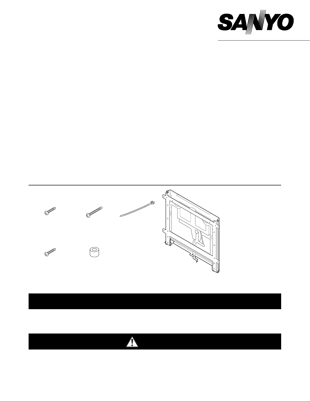
■ Parts contained in the package
1AA6P1P4051-- (IDLKB)
Installation of the Plasma Display needs special knowledge. Installation should be made by
qualified personnel.
NOTES ON INSTALLATION
• For customers safety, please install only after being careful to ascertain whether the place to
which it is to be mount is capable of supporting the combined weight of the Plasma Display
set and the Tilt Mount Unit together.
• Please make sure that at least two people are present during installation.
• Please make sure that all the screws and parts specified in the installation manual are used
in full number on installation.
IMPORTANT NOTICE
The Tilt Mount Unit is intended for use only with the SANYO Plasma Display model number
series PDP-42WV1, PDP-42WV2. Use with other apparatus is capable of resulting in instability causing possible injury.
CAUTION
Screws A (M8 x 30)
(4pcs.)
Screws B (M8 x 60)
(4pcs.)
Spacers
(4pcs.)
Bundling Band
(2pcs.)
•
Phillips
screwdriver, # 2 tip.
•
Phillips
screwdriver, # 2 tip
with 12" shaft.
■ Required tools
Screws C (M5 x 20)
(1pcs.)
Printed in Japan
Page 2
2
Please carry out installation only after making absolutely sure that the surface of wall
is capable of bearing the total weight over a long period of time along with any reasonable stress resulting from earthquake or other external stresses.
If installation is carried out incorrectly or the strength of the wall is not properly ascertained,
this may lead to the Plasma Display falling down from its mountings and serious accident
occurring. Please carry out installation correctly in line with the following points.
• The surface of the wall must be able to support the combined weight of the Unit and the
Plasma Display together. Check the weight of the Unit and of the Display Unit before installation and then check the load-bearing capacity of the wall. If the load-bearing capacity of
the wall is insufficient, please use plenty of reinforcement.
• Weight of Unit . . . . . . . . . .approx. 10.7kg (23.6 lbs)
• Weight of Plasma Display . .Refer to Instruction Manual. When speakers are used with
Display, weight of speakers must also be taken into
account.
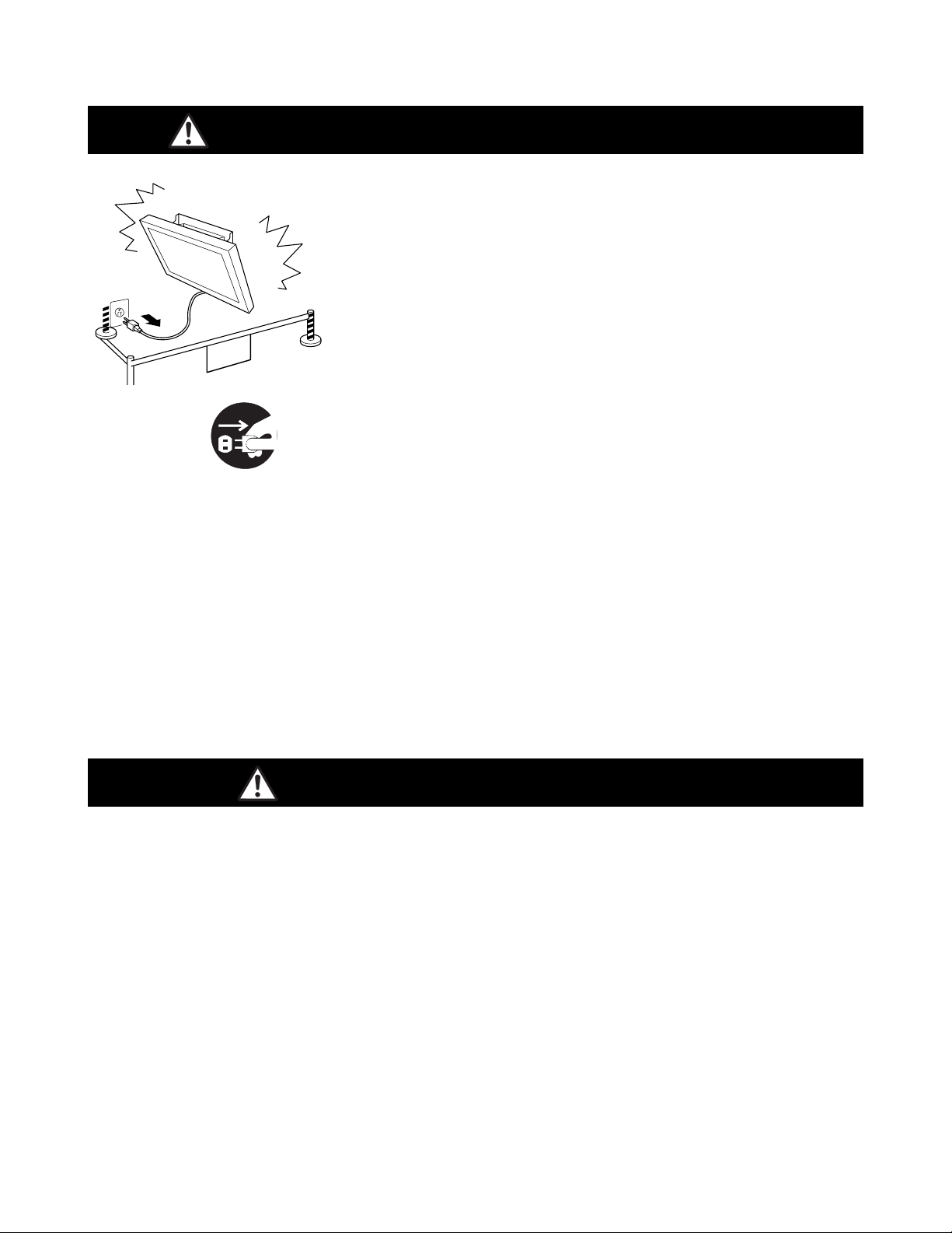
CAUTION FOR INSTALLATION
If anything abnormal occurs, please remove plug and stay
away.
If there is any looseness, coming-away or unevenness in the
screws or other parts of the product, there is a danger that it
may fall off its mountings. In this case, and again, if there is any
smoke or strange smell, or if water or any other alien substance
gets into the screen, no picture appears on the screen, or there
is damage to the equipment, please do not use the Display, as
this may lead to accident or injury. After taking the following
steps, please contact your nearest sales dealer. Please do not
attempt any adjustment or repair work by yourself, as this may
be dangerous.
➀ Turn off the Display and remove the Power plug from wall out-
let.
➁ Enclose the area in order not to enter under the Plasma
Display.
WARNING FOR SAFETY INSTRUCTION
Contact to service center to take care of any necessary adjustment.
Please be sure to ask a service personnel to take care of any necessary moving, adjusting of
direction or angle. This is dangerous, so the customer should under no circumstances attempt
this by themselves as this may lead to accidents and injury.
Do not put weight on apparatus by hanging from or pulling on cord.
Do not under any circumstances hang from the Display unit once it is attached to wall, as this
may lead to it falling down, causing serious accident or even injury. Please be careful to make
sure that children refrain from doing this. Also, please be careful not to put any weight on the
apparatus by pulling the attached wires.
Please remove plug!
DANGER
Page 3

3
• Make sure that the unit is out of the way of swinging doors or doors on furniture on installation. Do not install in any place where there is excess vibration or load as this may lead to
the unit falling down from its mountings, damage or injury.
• Do not install in bathroom, shower unit, outside, near window or anywhere where water might
come into contact with the unit as this may lead to fire or electric shock.
• Do not install near to the inlet or outlet for an air-conditioning system or anywhere where
there is dust, soot or a lot of tobacco smoke as this may lead to fire or breakdown of the
equipment.
• Do not install anywhere where the temperature is high or with high humidity as this may lead
to fire or electric shock.
• Do not install on the ceiling or any surface at an acute angle as this may cause heat to build
up internally, temperature to rise and fire to occur or the equipment to fall down from its
mountings, causing it to be damaged or injury to be sustained.
• Do not install in such a way as to close of the ventilation holes. Leave minimum distance (
more than 10cm for top and side, 6cm for bottom, and 3cm for behind) free around the ventilation holes so as to not impede proper ventilation. If internal temperature rises, this may
lead to fire or accident.
• Do not install near sprinklers or sensors as this may lead to malfunction or electric shock.
CAUTION FOR LOCATION OF INSTALLATION
• When mounting the Plasma Display to the installed Tilt Mount Unit, please check that the
brackets on the Display are properly slotted into the brackets on the Mounting unit. Please
make sure to tighten the screws and secure the unit from behind after loading. Failure to do
so may lead to the unit falling down from its mountings, accident or injury.
• Do not customize any of the parts and do not use any damaged parts as this may lead to the
unit falling down from its mountings,accident or injury.
• Use the correct number of screws and bolts in the correct positions as indicated. Only use
the brackets provided. Failure to do so may lead to the unit falling down from its mountings,
accident or injury.
• Be careful not to get fingers trapped in wall brackets.
CAUTION IN INSTALLATION
• Make absolutely certain that the weight of the unit is supported by pillars and beams made
of strong material.
• Do not attempt to directly mount to any wall that is not strong enough. Please do not attach
to decorative, non-load-bearing beams or ceiling brackets.
• If mounting to a concrete wall, please make sure to use anchors of sufficient strength to support total load.
Do not allow unit to get get! Do not use in bathroom or
shower unit!
Page 4
4
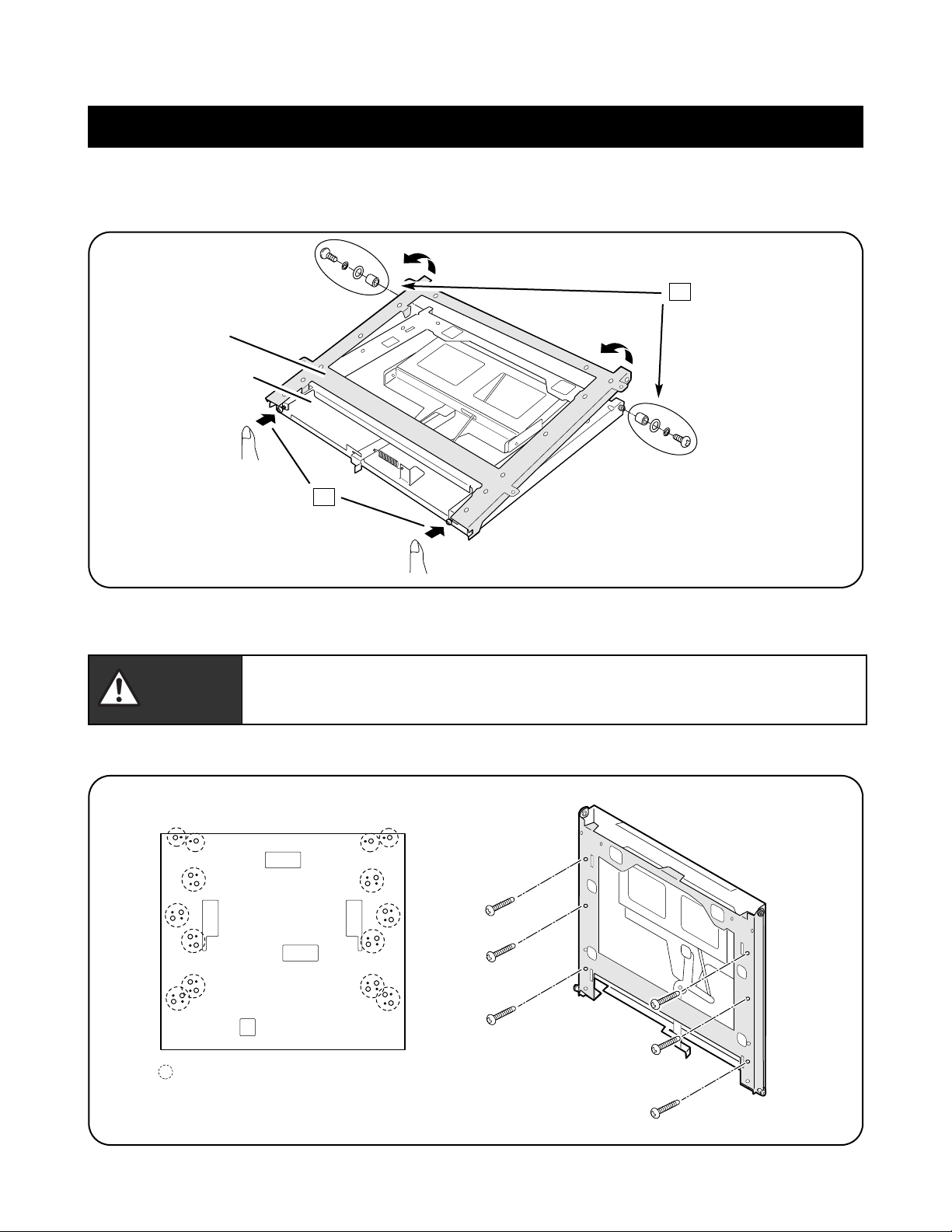
3. Mount the Mounting Unit on the wall with screws (not supplied).
Disassemble the Tilt Mount Unit.
1. Remove 2 screw kits (D :screw, spacer ring and 2 washers).
2. Press and hold 2 screws, and lift the upper part of the Frame. Pull the Frame away from the Mounting Unit.
Installation
1
Frame
Mounting Unit
2
: Available screw holes.
Choose the appropriate hole position
to mount the Mounting Unit.
Remove 2 screw kits (D).
Press and hold the screws,
and lift the upper part of the
Frame.
Rear of the Mounting Unit
Install the Frame and Mounting Unit.
CAUTION
• Make sure the wall and screws have sufficient strength to sustain the load.
• After installation, make sure the Frame and Mounting Unit are securely tightened with
screws
Page 5

5
4. Mount the Frame on the Plasma Monitor with 4 screws (A). If you need the space between the Plasma Monitor
and Wall, pat 4 spacers between the Frame and Plasma Monitor and mount with 4 screws (B).
5. Make sure the shaft screws are securely tighten. Hook the Frame on to the shaft screws of the Mounting Unit.
6. Lift the Plasma Monitor up, press it firmly in place.
7. Fix the Frame and Mounting Unit with 2 screw kits (D).
5
Hook the Frame.
6
Lift the the Plasma
Monitor.
7
Tighten 2 screw kits (D) to fix
the Frame and Mounting Unit.
D
Attach the Frame to the Mounting Unit.
CAUTION
• Working with more than two people to handle the Plasma Monitor.
• Be careful not to catch your finger between the Frame and Mounting Unit.
NOTE :
The surface must be flat and
maintained with soft material
(cloth or blanket) for protecting
the screen surface.
Soft Cloth
If you need the space between the
Plasma Monitor and Wall, pat 4 spacers
under the Frame.
spacers
screws A
screws B
Page 6

6
8. With holding the Plasma Monitor, press the angle adjustment lever left to adjust the angle of the Plasma
Monitor.
9. When you finished, fix the angle adjustment lever with the screw (C).
0°
20°
9
Tighten the screw (C).
8
Press the lever to tilt the
Plasma Monitor.
NOTE : Available tilt angle are : 0°, 5°, 10°, 15° and 20°.
Tilt the Plasma Monitor.
CAUTION
• Be sure to hold the Plasma Monitor when tilting it, otherwise it may fall and that may
result in damage.
NOTE :
Make sure all screws are
securely tightened.
Page 7

7
Connecting cables
1. Verify 2 screw kits on the top of the Frame are securely tightened.
2. Remove the screw (C). With holding the Plasma Monitor, press the angle adjustment lever left to tilt the Plasma
Monitor to 20°.
3. Remove the shaft screws and spacer rings.
2
3
20°
Remove the shaft screws
and spacer rings.
Remove the screw (C),
and tilt the Plasma
Monitor to 20°.
CAUTION
• Be sure to hold the Plasma Monitor when connecting cables, otherwise it may fall and
that may result in damage.
shaft screw
spacer ring
Page 8

8
4. Hold the lower part of the Plasma Monitor. Push the screws of the Frame all way up, and pull the lower part of
the Plasma Monitor out.
5. Connect the cables.
6. To put the Plasma Monitor and Tilt Mount Unit back in place, reverse the steps 2~4.
Push the screws of the Frame, and pull
the lower part of the Plasma Monitor out.
CAUTION
• Working with more than two people to handle the Plasma Monitor.
Mounting
Unit
Frame
Plasma
Monitor
Page 9

9
Uninstall Tilt Mount Unit
1. Remove the screw (C). With holding the Plasma Monitor, press the angle adjustment lever left to set the angle
of the Plasma Monitor to 0°.
2. Verify 2 screws on bottom of the Mounting Unit are securely tightened.
CAUTION
• Working with more than two people to handle the Plasma Monitor.
3. Remove 2 screw kits on the top of the Frame.
4. Push and hold 2 screws on the bottom of the Mounting Unit, and tall down the Plasma Monitor frontward and
remove.
Remove the screw (C),
and press the angle lever
left to set the angle to 0°.
Verify 2 screws are
securely tightened.
2
1
0°
Remove 2 screw kits.
3
Push and hold 2 screws, and put the
Plasma Monitor and Frame down.
4
Pull the Plasma Monitor and Frame
away from the Mounting Unit.
Page 10

10
Fixing Cables
In order to prevent damage to or tangling up of power cords and signal cables, cables and cords can be secured
with the bundling band. See the figure below and secure these cables and cords proper positions
2 holes for inserting the
bundling bands.
Insert the bundling band into
the hole.
Bundling cords together
using the bundling band.
Page 11

11
Units : mm
Weight : 10.7 kg (23.6 lbs)
Adaptable Plasma Monitor
: PDP-42WV1, PDP42-WV2
Measurements :
Specifications
A
187
190
13
13
17
8
2 -
φ
φ
2 -
5
20
518
452
A B
20
131
452
518
618
13
13
13
2 - φ5
329
20.0º
13
2 -
13
φ
8
2 -
φ
5
13
25.5
107
140
508
101.5
20 20 20
8.5
159.5
13
102 33
2 -
2 -
2 -
2 -
φ
5
13
20
2 - φ8
20
φ
8
13
1
φ
5
13
20
φ
8
13
1
13
13
1
B
2 - φ5
20
2 - φ8
13
1
Page 12

12
 Loading...