

Page 1
1MATSUI 25 M1
General Information
Chassis: EB2-A (Sanyo)
Also Covers: Matsui 28 M1
Matrix
Item See Model Book
IF Adjustments.....................................................................................Sanyo CB 5149 4
Memory IC Replacement .................................................................... Sanyo CB 5149 4
Block Diagram .....................................................................................Sanyo CB 5957 4
Electrical Adjustments........................................................................ Sanyo CB 5957 4
IC Voltages ...........................................................................................Sanyo CB 5959 4
Text PCB............................................................................................... Sanyo CB 5959 4
NICAM Diagram ...................................................................................Sanyo CB 5959 4
Recommended Safety Parts
Item Part No. Description
Q901 414 008 6405 CRT A59ECF20X05
L901 645 003 0031 COIL,DEGAUSSING
645 003 0062 COIL,DEGAUSSING
W901 645 000 2458 CORD,POWER
K601 610 233 7990 CRT SOCKET
C301 404 047 3602 MT-POLYEST 0.1U M 125V
404 044 0901 MT-COMPO 0.1U M 250V
C302 404 047 3602 MT-POLYEST 0.1U M 125V
404 044 0901 MT-COMPO 0.1U M 250V
C331 404 060 6505 CERAMIC 2200P M 400V
404 060 6604 CERAMIC 2200P M 400V
C420 404 044 1502 MT-POLYPRO 6200P J 1.5K
404 046 8806 MT-POLYPRO 6200P J 1.5K
C423 404 040 8109 MT-POLYPRO 5600P J 1.5K
404 040 7805 MT-POLYPRO 5600P J 1.5K
C441 403 082 7804 POLYPRO 0.18U J 200V
C442 403 082 6906 POLYPRO 0.12U J 200V
R301 401 008 8607 CARBON 220K JA 1/2W
R331 402 000 8305 SOLID 5.6M KA 1/2W
R332 402 000 8305 SOLID 5.6M KA 1/2W
T381 610 033 3758 POWER TRANS
610 240 4722 POWER TRANS
T471 645 003 3094 TRANS,FLYBACK
L301A 610 221 6912 LINE FILTER
D315 407 105 8700 PHOTO COUPLE PC113B
408 009 8407 PHOTO COUPLE CNY17F-30PT6
F301 423 022 2102 FUSE 250V 4A
PS301 408 013 3801 TH PTH 451C262BF140M270
SW301 645 003 6811 SWITCH,PUSH POWER 2P-2T
Q901 414 008 6306 CRT A66ECF20X05
L901 645 003 0048 COIL, DEGAUSSING
645 003 0055 COIL, DEGAUSSING
W901 645 000 2458 CORD, POWER
C301 404 047 3602 MT-POLYEST 0.1U M 125V
404 044 0901 MT-COMPO 0.1U M 250V
C302 404 047 3602 MT-POLYEST 0.1U M 125V
404 044 0901 MT-COMPO 0.1U M 250V
C331 404 060 6505 CERAMIC 2200P M 400V
404 060 6604 CERAMIC 2200P M 400V
C420 404 060 7809 MT-POLYPRO 6000P J 1.5K
404 060 7908 MT-POLYPRO 6000P J 1.5K
C423 404 040 8109 MT-POLYPRO 5600P J 1.5K
404 040 7805 MT-POLYPRO 5600P J 1.5K
C441 403 082 7804 POLYPRO 0.18U J 200V
C442 403 082 7408 POLYPRO 0.15U J 200V
R301 401 008 8607 CARBON 220K JA 1/2W
R331 402 000 8305 SOLID 5.6M KA 1/2W
R332 402 000 8305 SOLID 5.6M KA 1/2W
T311 645 003 2998 TRANS POWER PULSE
T471 645 003 3094 TRANS, FLYBACK
L301A 610 221 6912 LINE FILTER
D315 407 105 8700 PHOTO COUPLE PC113B
408 009 8407 PHOTO COUPLE CNY17F-30PT6
F301 423 022 2102 FUSE 250V 4A
PS301 408 013 3801 TM PTH451C262BF140M270
SW301 645 003 6811 SWITCH,PUSH POWER 2P-2T
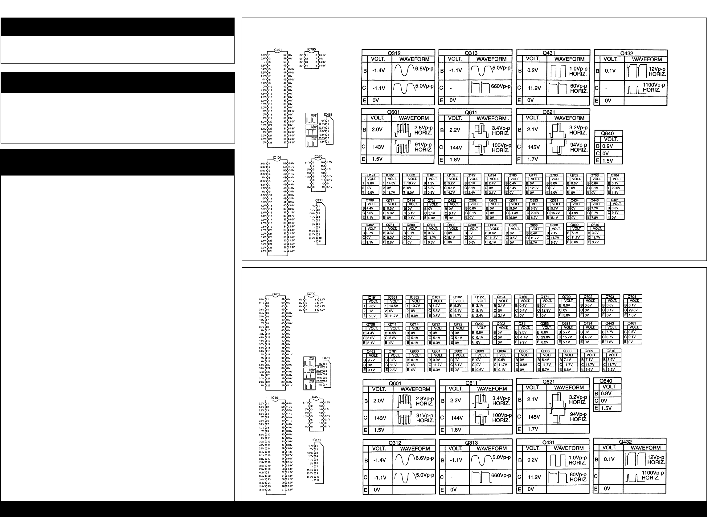
Main Diagram IC’s Voltage Charts & Waveforms (25 M1 only)
Main Diagram IC’s Voltage Charts & Waveforms (28 M1 only)
Safety Parts / Main Diagram IC’s Voltage Charts & Waveforms (25 M1 only) / (28 M1 only) / Main Diagram (25 M1 only) / (28 M1 only)
Page 2
MATSUI 25 M1
2
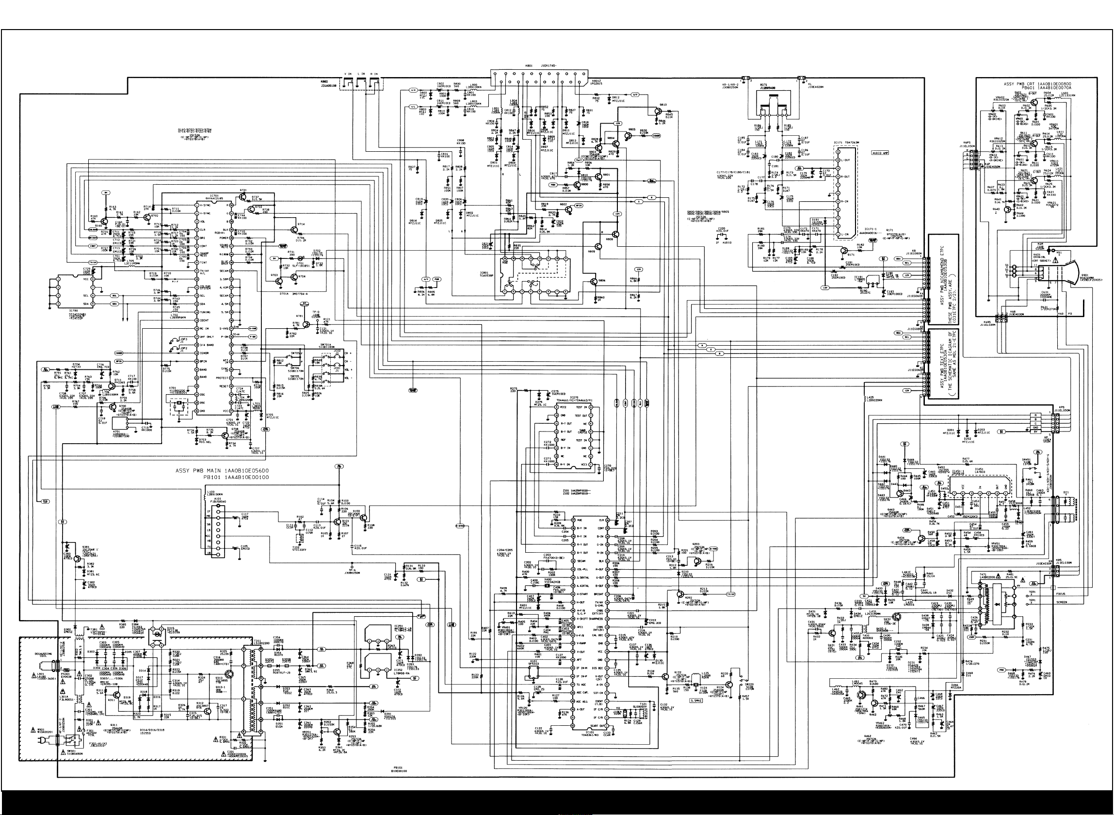
Main Diagram (25 M1 only)
Safety Parts / Main Diagram IC’s Voltage Charts & Waveforms (25 M1 only) / (28 M1 only) / Main Diagram (25 M1 only) / (28 M1 only)
Page 3
3MATSUI 25 M1
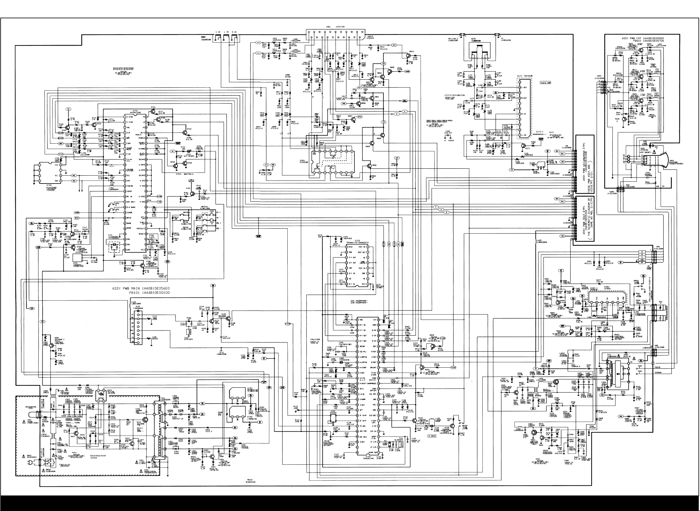
Main Diagram
(28 M1 only)
Safety Parts / Main Diagram IC’s Voltage Charts & Waveforms (25 M1 only) / (28 M1 only) / Main Diagram (25 M1 only) / (28 M1 only)
Page 4
SANYO CB 5149
Circuit Alignment
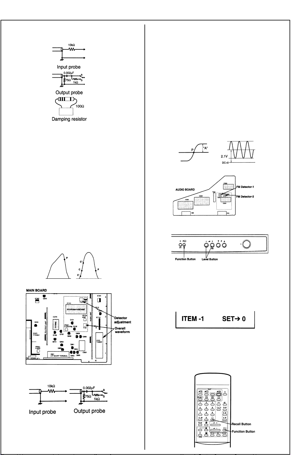
VIF Alignment
Fig 1.
Setting Detector CH Trap
Adjustment Adjustment
DCl5V IC351-1 IC351-1
AGO Voltage lC101-48p lC101-48p
Output Probe Tuner TP Tuner TP
(side B) (side B)
Input Probe Q124-E 124-E
Band No No
Damping R No KU1 & KU-2
System SW I I
Sweep ATT 25 25
Adjustment By using T121 By using
adjust “P’ to Tuner
be maximum converter coil
amplitude and T101,
make the
marker
positions to:
P = 30 +/- 10%
C = 30 +/- 10%
VIF Waveform
Setting Detector CH Trap
Adjustment Adjustment
DC 15V IC901 -15 pin IC901-15pin
AGC Voltage IC901 -3 pin Output Probe IC901-1 pin IC901-12pin
(side B) (side B)
Input Probe IC901-14pin IC901-6pin
Sweep ATT 10 (Condition)
Marker
Frequency 39.5 Mhz Carrier freq.:
6.0mhz
Modulation
freq.:
1khz (sine w/f)
Adjustment 1: Adjust AGC By using T902
voltage to be adjust DC
“A”=0.5Vp-p level to be
2: By using 2.1V
adjust “P” to
be equal
centre line
VIF Waveform
Fig 4.
Memory IC Replacement (Important Notice)
Fig 5.
Fig 2.
SIF Alignment
Fig 3.
When you replace a memory IC (IC790), it is necessary to
initialise the IC as follows.
Initialisation of Memory IC
1: When you press and hold the Function button on the TV set
and then press the Recall button on the RC transmitter, the
following picture will appear on the screen. (fig. 6)
Fig 6.
2: Confirm SET number of all items is “0” by pressing the
Function button.
3: If it is not “0” change to “0” by the Level (+/-) button.
(Changing the SET number, automatically memorised).
4: Press the Recall button to return to normal TV mode.
Fig 7.
Page 5

SANYO CB 5957
Service Adjustments
Service Control Adjustment
B1 Power Supply Adjustment
1: Set VR351 to be mechanical centre before pressing the main
switch.
2: Tune the receiver to PAL circular pattern.
3: Set brightness and contrast controls to normal.
4: Connect digital voltmeter to R791 (VR351 side).
5: By using VR351, adjust voltage to 130 ± 0.5V (for 21’). By
using VR351, adjust voltage to 150 ± 0.5v (for 25” and 28”).
AFT Adjustment
1: Tune the receiver to the clearest station.
2: By using T121, adjust AFT to obtain best picture.
AGC Adjustment
Note: Do not attempt this adjustment with a weak signal.
1: Tune the receiver to the clearest station.
2: Set AGC VR (VR120) in direction which causes snow noise to
appear, then in the opposite direction until snow noise just
disappears.
Grey Scale Adjustment
(Screen VR Adjustment)
1: Tune the receiver to white pattern.
2: Set brightness control to display centre and contrast control to
normal.
3: Set SW220 to ‘SERVICE” position.
4: Set VR602 and VR61 2 to be mechanical centre.
5: Turn VR601, VR611 and VR621 fully counter-clockwise.
6: Set screen VR for one colour to be just visible.
(Bias VR Adjustment)
7: By using VR601, VR611 or VR621, adjust line until white.
8: Set SW220 to “NORMAL” position.
(Drive VR Adjustment)
9: By using VR602 and VR612, adjust white balance.
High Voltage and Width Adjustment (High Voltage Adjustment)
1: Tune the receiver to PAL circular pattern.
2: Set brightness and contrast controls to maximum.
3: Connect digital voltmeter to both terminals of R232 (left side)
(+)‘ and a high voltage meter to the CRT anode.
4: Confirm high voltage to be 25.0 ± 1 kV at beam current 1 .0,
and less than 28.0 kV at 0 beam current (for 21”). Confirm
high voltage to be 26.0 ± 1 kV at beam current 1.1 and less
than 29.0kV at 0 beam current (for 25” and 28”).
(H-Width Adjustment)
5: If H-width is too wide or narrow, connect or disconnect a lead
wire J150 (for 21”). Adjust VR462 to obtain proper H-width (for
25” and 28”).
6: Reconfirm high voltage.
H-Centre Adjustment
1: Tune the receiver to the circular pattern.
2: Adjust H-centre by using VR4O1.
V-Centre Adjustment
1: Tune the receiver to circular pattern.
2: Adjust V-centre by using 5W451.
V-Size Adjustment
1: Tune the receiver to the circular pattern.
2: Adjust V-size by using VR451.
Focus Adjustment
By using FOCUS VR, adjust focus control for good scanning
lines.
Page 6

SANYO CB 5959
NICAM
Diagram
Page 7

SANYO CB 5959
Block Diagram IC Diagrams
Main
Audio
 Loading...