

Page 1
INSTRUCTION MANUAL
REMOTECONTROLLER RB-SL50
REPEAT A- B ANGLE ONSCREEN
TOPMENU RETURN
SETUP MENU
AUDIO SUBTITLERANDOM ZOOM
PROGRAM
REV PLAY FWD
NEXTPREV
SLOW PAUSE/STEP SEARCHMODE
ON OPEN/CLOSE
123
6
98
5
4
7
0
+10
ENT
zq
a
n
f
e
cd
k
STOP
DVD Video Player
DWM-450
SANYO’S HELP-LINE
Call the toll-free number below if you have any difficulties operating this product.
1-800-813-3435 (Weekdays: 7:30 AM - 4:00 PM Central Time)
Please Read This Manual.
Because DVD is a new technology, we recommend that you read this manual carefully before connecting your
DVD video player and operating it for the first time.
Keep the manual in a safe place for future reference.
80M2000270001 DWM-450, Issue Number 1
English
Page 2

CONTENTS
Important Safety Instructions .....................................E2
Safety Certification ......................................................E4
Accessories ..................................................................E4
Controls ........................................................................ E5
Remote Control ............................................................E6
Before Connection .......................................................E7
Choosing a Connection ............................................E7
Basic Connections .......................................................E8
Connecting to a Conventional TV (Example 1) ........E8
Connecting to a TV with Progressive-scan Capability
(Example 2) ..............................................................E10
Additional Connection Examples ............................... E11
Connecting to an Audio System and TV
(Example 3) ..............................................................E11
Connecting to an Amplifier with Dolby Digital Decoder
or MPEG2 Decoder (Example 4) ..............................E12
Connecting to a Digital Amplifier (Example 5) .......... E12
Connecting to an Amplifier with Dolby Pro Logic Decoder
(Example 6) ..............................................................E13
Power Supply ........................................................... E13
For Safe and Efficient Operation ................................E13
Playable Discs ..............................................................E14
Basic Operation............................................................E15
Preparations .............................................................E15
Basic Playback .........................................................E15
Stopping Playback ....................................................E16
Selecting a DVD Menu .............................................E17
Selecting a Top Menu [DVD] ....................................E17
Chapter (Track) Skip ................................................ E17
Title or Chapter Search [DVD] ..................................E18
Time Search [DVD]...................................................E18
Time Search [CD] ..................................................... E18
Track Search [CD] .................................................... E18
Fast Playback ........................................................... E19
Slow Motion Playback [DVD] ....................................E19
Still Picture (Pause) .................................................. E19
Frame by Frame Advance Playback [DVD] ..............E19
Picture Zoom [DVD] ................................................. E20
Viewing from a Desired Camera Angle
(Multi-Angle) [DVD] .................................................. E20
Repeat Playback ...................................................... E21
Designated Range Repeat Playback (A-B Repeat) ..
Random Playback [CD] ............................................E22
Programmed Playback [CD] ..................................... E22
Selecting Subtitle Language [DVD] ..........................E23
Selecting Audio Soundtrack Language
(Multi-Language) [DVD]............................................E23
Selecting On-Screen Information ............................. E24
TVGuardian
Before Setting...........................................................E25
Setting TVGuardian
How It Works After Setting TVGuardian
MP3 CD Operation .......................................................E27
Before Starting ......................................................... E27
MP3 CD Playback .................................................... E27
Stopping Playback ....................................................E27
Pause ....................................................................... E28
File Skip....................................................................E28
Repeat Playback ...................................................... E28
To Check the Elapsed Playing Time ......................... E28
Picture Disc Operation ................................................E29
KODAK Picture CD Playback ................................... E29
JPEG CD Playback .................................................. E30
Picture Zoom ............................................................E30
Initial Settings ...............................................................E31
Setting Language ..................................................... E31
Setting Display ......................................................... E32
Setting Digital Out .................................................... E33
Setting Parental ........................................................ E34
Troubleshooting Guide ................................................E35
Maintenance .................................................................E36
Specifications ............................................................... E36
Warranty........................................................................E37
®
Operation ............................................... E25
®
................................................E25
®
..................E26
E21
IMPORTANT INFORMATION:
To connect this unit to a TV, TV must have a set of Audio/Video composite input jacks (RCA-type). You cannot
use an antenna terminal to connect this unit.
To operate the built-in TVGuardian
®
This unit has the built-in TVGuardian® Foul Language Filter (TVG®).
When a disc supporting closed caption is played, it will mute the audio during the entire phrase containing
offensive language. For more details, see page E25.
To enjoy Dolby Digital sound
For connection, see “Connecting to an Amplifier with Dolby Digital Decoder or MPEG2 Decoder (Example 4)” on
page E12.
See “Setting Digital Out” in the INITIAL SETTINGS on page E33.
Note:
This handling description is printed prior to product development.
When a part of the product specification must be changed to improve operability or other functions, priority is given to the product specification
itself. In such instances, the instruction manual may not entirely match all the functions of the actual product.
Therefore, the actual product and packaging, as well as the name and illustration, may differ from the manual.
-E1-
Page 3
CAUTION
RISK OF ELECTRIC SHOCK
DO NOT OPEN
This symbol indicates that dangerous voltage constituting a risk of electric shock is
present within this unit.
CAUTION: TO PREVENT THE RISK OF ELECTRIC
SHOCK, DO NOT REMOVE COVER (OR BACK).
REFER SERVICING TO QUALIFIED SERVICE PERSONNEL.
NO USER-SERVICEABLE PARTS INSIDE.
WARNING: TO PREVENT FIRE OR SHOCK HAZ-
ARD, DO NOT EXPOSE THIS APPLIANCE TO RAIN
OR MOISTURE.
IMPORTANT SAFETY INSTRUCTIONS
1. Read Instructions – All the safety and operating instruc-
tions should be read before the product is operated.
2. Retain Instructions – The safety and operating instructions should be retained for future reference.
3. Heed Warnings – All warnings on the product and in the
operating instructions should be adhered to.
4. Follow Instructions – All operating and use instructions
should be followed.
5. Cleaning – Unplug this product from the wall outlet before cleaning. Do not use liquid cleaners or aerosol cleaners.
Use a damp cloth for cleaning.
6. Attachments – Do not use attachments not recommended by the product manufacturer as they may cause
hazards.
7. Water and Moisture – Do not use this product near water – for example, near a bath tub, wash bowl, kitchen sink, or
laundry tub; in a wet basement; or near a swimming pool;
and the like.
8. Accessories – Do not place this product on an unstable
cart, stand, tripod, bracket, or table. The product may fall,
causing serious injury to a child or adult, and serious damage
to the product. Use only with a cart, stand, tripod bracket, or
table recommended by the manufacturer, or sold with the
product. Any mounting of the product should follow the
manufacturer’s instructions, and should use a mounting accessory recommended by the manufacturer.
PORTABLE CART WARNING
9. A product and cart combination
should be moved with care. Quick stops,
excessive force, and uneven surfaces
may cause the product and cart combination to overturn.
(Symbol provided by RETAC)
This symbol indicates that there are important operating and maintenance instructions in the literature accompanying this
unit.
WARNING: UNAUTHORIZED RECORDING OF
COPYRIGHTED MATERIAL MAY VIOLATE APPLICABLE COPYRIGHT LAWS. THE MANUFACTURER
ASSUMES NO RESPONSIBILITY FOR UNAUTHORIZED DUPLICATION, USE OR OTHER ACTS WHICH
INFRINGE UPON THE RIGHTS OF COPYRIGHT
OWNERS.
10. Ventilation – Slots and openings in the cabinet are provided for ventilation and to ensure reliable operation of the
product and to protect it from overheating, and these openings must not be blocked or covered. The openings should
never be blocked by placing the product on a bed, sofa, rug,
or other similar surface. This product should not be placed in
a built-in installation such as a bookcase or rack unless proper
ventilation is provided or the manufacturer's instructions have
been adhered to.
11. Power Sources – This product should be operated only
from the type of power source indicated on the marking label.
If you are not sure of the type of power supply to your home,
consult your product dealer or local power company. For products intended to operate from battery power, or other sources,
refer to the operating instructions.
12. Grounding or Polarization – This product may be
equipped with a polarized alternating-current line plug (a plug
having one blade wider than the other). This plug will fit into
the power outlet only one way. This is a safety feature. If you
are unable to insert the plug fully into the outlet, try reversing
the plug. If the plug should still fail to fit, contact your electrician to replace your obsolete outlet. Do not defeat the safety
purpose of the polarized plug.
13. Power-Cord Protection – Power-supply cords should be
routed so that they are not likely to be walked on or pinched
by items placed upon or against them, playing particular attention to cords at plugs, convenience receptacles, and the
point where they exit from the product.
14. Lightning – For added protection for this product during
a lightning storm, or when it is left unattended and unused for
long periods of time, unplug it from the wall outlet and disconnect the antenna or cable system. This will prevent damage
to the product due to lightning and power-line surges.
S3125A
(Figure 1)
-E2-
Page 4
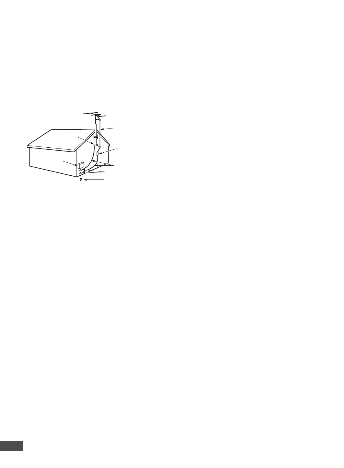
15. Outdoor Antenna Grounding – If an outside antenna or
cable system is connected to the product, be sure the antenna or cable system is grounded so as to provide some
protection against voltage surges and built-up static charges.
Article 810 of the National Electrical Code, ANSI/NFPA 70,
provides information with regard to proper grounding of the
mast and supporting structure, grounding of the lead-in wire
to an antenna discharge unit, size of grounding conductors,
location of antenna-discharge unit, connection to grounding
electrodes, and requirements for the grounding electrode. See
Figure 2.
EXAMPLE OF ANTENNA GROUNDING AS PER NATIONAL ELECTRICAL CODE, ANSI/NFPA 70
18. Object and Liquid Entry – Never push objects of any
kind into this product through openings as they may touch
dangerous voltage points or short-out parts that could result
in a fire or electric shock. Never spill liquid of any kind on the
product.
19. Servicing – Do not attempt to service this product yourself as opening or removing covers may expose you to dangerous voltage or other hazards. Refer all servicing to qualified service personnel.
20. Damage Requiring Service – Unplug this product from
the wall outlet and refer servicing to qualified service personnel under the following conditions:
ANTENNA
LEAD IN
GROUND
CLAMP
ELECTRIC
SERVICE
EQUIPMENT
WIRE
ANTENNA
DISCHARGE UNIT
(NEC SECTION 810-20)
GROUNDING CONDUCTORS
(NEC SECTION 810-21)
GROUND CLAMPS
POWER SERVICE GROUNDING
ELECTRODE SYSTEM
(NEC ART 250, PART H)
NEC – NATIONAL ELECTRICAL CODE
S2898A
(Figure 2)
16. Power Lines – An outside antenna system should not
be located in the vicinity of overhead power lines or other
electric light or power circuits, or where it can fall into such
power lines or circuits. When installing an outside antenna
system, extreme care should be taken to keep from touching
such power lines or circuits as contact with them might be
fatal.
17. Overloading – Do not overload wall outlets, extension
cords, or integral convenience receptacles as this can result
in a risk of fire or electric shock.
a. When the power-supply cord or plug is damaged.
b. If liquid has been spilled, or objects have fallen into
the product.
c. If the product has been exposed to rain or water.
d. If the product does not operate normally by following
the operating instructions. Adjust only those controls that
are covered by the operating instructions as an improper
adjustment of other controls may result in damage and
will often require extensive work by a qualified technician
to restore the product to its normal operation.
e. If the product has been dropped or damaged in any
way.
f. When the product exhibits a distinct change in performance – this indicates a need for service.
21. Replacement Parts – When replacement parts are
required, be sure the service technician has used replacement parts specified by the manufacturer or have the same
characteristics as the original part. Unauthorized substitutions
may result in fire, electric shock, or other hazards.
22. Safety Check – Upon completion of any service or repairs to this product, ask the service technician to perform
safety checks to determine that the product is in proper operating condition.
23. Heat – The product should be situated away from heat
sources such as radiators, heat registers, stoves, or other
products (including amplifiers) that produce heat.
This appliance shall not be exposed to drippling or splashing
water and that no object filled with liquid such as vases shall
be placed on the apparatus.
-E3-
Page 5
SAFETY CERTIFICATION
REMOTECONTROLLER RB-SL50
REPEAT A-B ANGLE
TOPMENU RETURN
SETUP MENU
AUDIO SUBTITLE RANDOM ZOOM
PROGRAM
REV PLAY FWD
NEXTPREV
SLOW
ON OPEN/CLOSE
123
6
98
5
4
7
0
+10
ENT
zq
a
n
f
e
cd
k
STOP
This unit is made and tested to meet exacting safety standards.
It meets UL and FCC requirements and complies with safety
performance standards of the U.S. Department of Health and
Human Services.
CAUTION - USE OF CONTROLS OR ADJUSTMENTS OR
PERFORMANCE OF PROCEDURES OTHER THAN THOSE
SPECIFIED HEREIN MAY RESULT IN HAZARDOUS RADIATION EXPOSURE.
THIS UNIT SHOULD NOT BE ADJUSTED OR REPAIRED
BY ANYONE EXCEPT PROPERLY QUALIFIED SERVICE
PERSONNEL.
FCC INFORMATION
This device complies with Part 15 of the FCC Rules.
Operation is subject to the following two conditions:
(1) This device may not cause harmful interference, and (2)
this device must accept any interference received, including
interference that may cause undesired operation.
CAUTION:
Changes or modifications not expressly approved by Sanyo
may void the user’s authority to operate this equipment.
Note:
This equipment has been tested and found to comply with
the limits for a Class B digital device, pursuant to Part 15 of
the FCC Rules. These limits are designed to provide reasonable protection against harmful interference in a residential
installation. This equipment generates, uses and can radiate
radio frequency energy and, if not installed and used in accordance with the instructions, may cause harmful interference to radio communications. However, there is no guarantee that interference will not occur in a particular installation.
If this equipment does cause harmful interference to radio or
television reception, which can be determined by turning the
equipment off and on, the user is encouraged to try to correct
the interference by one or more of the following measures:
• Reorient or relocate the receiving antenna.
• Increase the separation between the equipment and
receiver.
• Connect the equipment into an outlet on a circuit different
from that to which the receiver is connected.
• Consult the dealer or an experienced radio/TV technician
for help.
THIS CLASS B DIGITAL APPARATUS COMPLIES
WITH CANADIAN ICES-003.
CET APPAREIL NUMÉRIQUE DE CLASSE B EST
CONFORME AUX EXIGENCES DU RÉGLEMENT
CANADIEN ICES-003.
ACCESSORIES
RB-SL50 wireless remote control Audio/Video cable
-E4-
Page 6
AUDIO OUT
S-VIDEOOUT
COAXIAL
COMPONENT VIEDO OUT
Pr
Y
L
Pb
VIDEOOUT
R
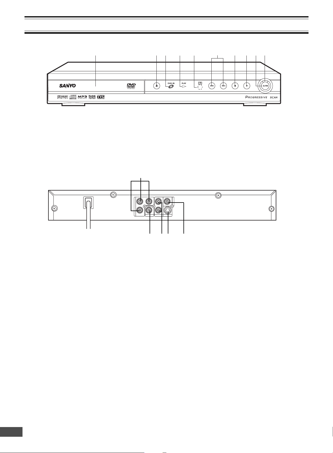
Front Panel
1 2 7 8 104 5 93
6
CONTROLS
1. Disc tray
2. Open/Close button (q)
3. Disc-in indicator (DISC IN)
4. Play indicator (PLAY)
5. Remote sensor (IR)
Back Panel
1. Component video output jacks
(COMPONENT VIDEO OUT)
2. Coaxial digital output jack (COAXIAL)
3. Audio output jacks (AUDIO OUT)
6. Skip/Next/Previous buttons (f, e)
7. Stop button (n)
8. Play button (a)
9. Power button (z/ON)
10. Power indicator
1
2453
4. S-Video output jack (S-VIDEO OUT)
5. Video output jack (VIDEO OUT)
-E5-
Page 7
REMOTE CONTROL
11
4
5
6
9
8
10
7
12
3
12
18
21
20
17
23
22
24
19
16
13
14
25
26
27
15
REMOTE CONTROLLER RB-SL50
REPEAT A - B ANGLE
TOPMENU RETURN
SETUP
MENU
AUDIO SUBTITLE RANDOM ZOOM
PROGRAM
REV PL AY FWD
NEXTPREV
SLOW
ON OPEN/CLOSE
123
6
98
5
4
7
0
+10
ENT
zq
a
n
f
e
cd
k
STOP
STOP
n
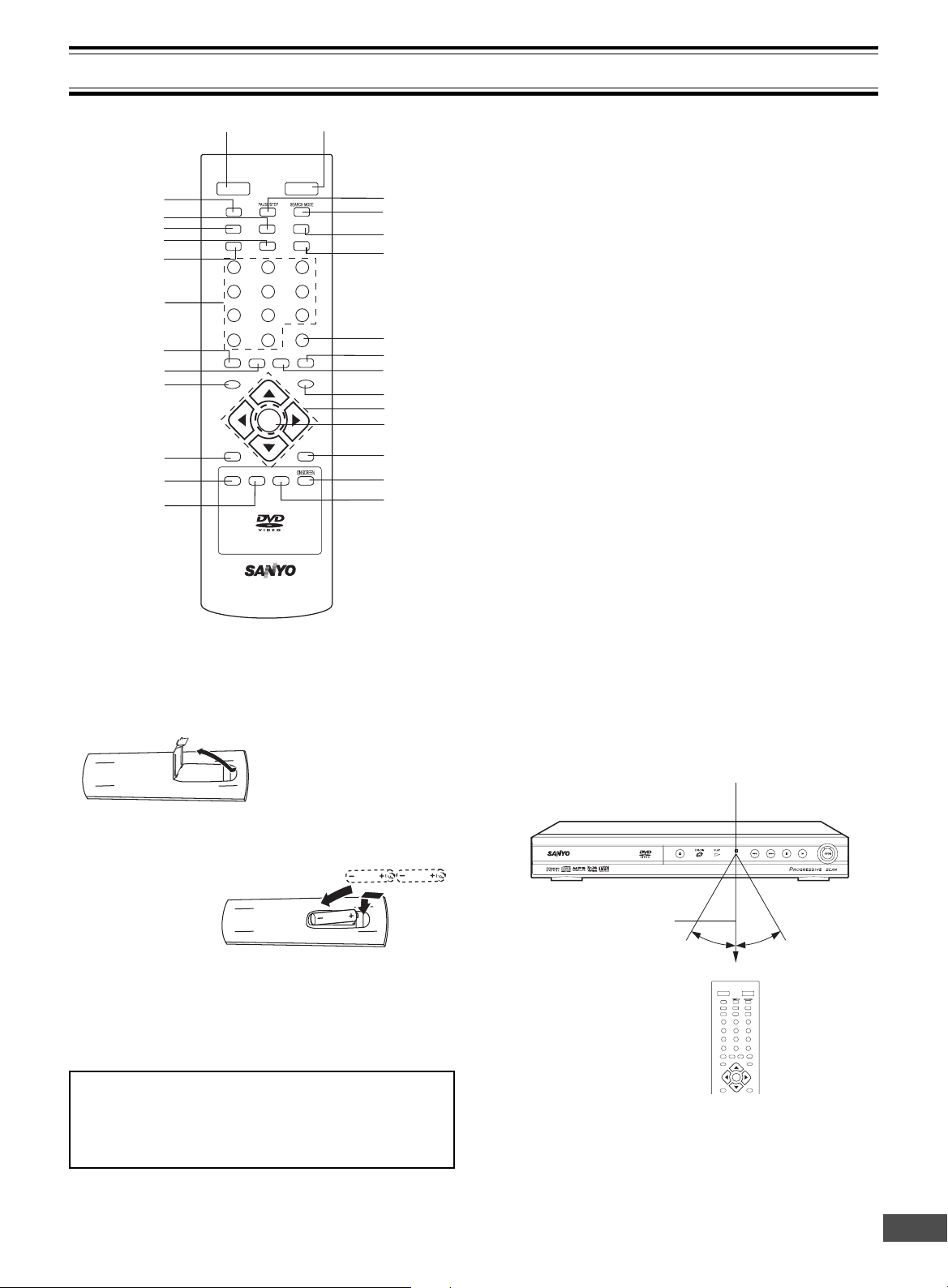
Controls
1. Power button (z/ON)
2. Open/Close button ( q OPEN/CLOSE)
3. Pause/Step button (k PAUSE/STEP)
4. Search mode button (SEARCH MODE)
5. Skip/Next button (NEXT e)
6. Forward button (FWD c)
7. Program button (PROGRAM)
8. Zoom button (ZOOM)
9. Random play button (RANDOM)
10. Menu button (MENU)
11. Directional arrow buttons (
12. Enter button (ENT)
13. Return button (RETURN)
14. On screen display button (ON SCREEN)
15. Angle button (ANGLE)
16. A-B repeat button (A-B)
17. Repeat button (REPEAT)
18. Top menu button (TOP MENU)
19. Setup button (SETUP)
20. Subtitle change button (SUBTITLE)
21. Audio button (AUDIO)
22. Number buttons (1-9, 0, +10)
23. Reverse button (REV d)
24. Play button (a PLAY)
25. Skip/Previous button (PREV f)
26. Stop button (n STOP)
27. Slow button (SLOW)
4
, a, 5, b)
Inserting batteries
1.
Note:
Remove the batteries if the remote control is not to be used
for a month or more. Batteries left in the unit may leak and
cause damage.
IMPORTANT NOTE:
SPENT OR DISCHARGED BATTERIES MUST BE RECYCLED OR DISPOSED OF PROPERLY IN COMPLIANCE WITH ALL APPLICABLE LAWS.
FOR DETAILS INFORMATION, CONTACT YOUR LOCAL COUNTY SOLID WASTE AUTHORITY.
2.
Two “AAA” batteries (not supplied)
Remote control range
Remote sensor
Within approx. 20 feet
(6 meters)
Note:
This is not multibrand remote control.
30° 30°
ON OPEN/CLOSE
z
SLOW
k
f
n
REV PLAY FWD
a
123
4
5
7
+10
0
AUDIO SUBTITLE RANDOM Z O O M
SETUP MENU
ENT
TOPMENU RETURN
q
NEXTPREV
e
cd
6
98
PROGRAM
-E6-
Page 8
BEFORE CONNECTION
IMPORTANT INFORMATION:
• To connect this unit to a TV, TV must have a set of Audio/Video composite input jacks (RCA-type).
You cannot use an antenna terminal to connect this unit.
• If your TV has only an antenna terminal, please purchase the TV with Audio/Video input jacks or the RF
modulator.
• Do not connect the unit to a VCR directly. The playback picture will be distorted because DVD video discs are
copy-protected.
• Please refer to the instruction manuals for the components that you are connecting (TV, AV amplifier, etc.).
Choosing a Connection
Does your TV have “Audio/Video input jacks”?
x x x x x x x x x x x x
x
Yes No
x
TV Connection
x
TV and Amplifier Connection
x x x x
x
VIDEO Connection
x
AUDIO Connection
x
Do you use an RF Modulator (not supplied)?
Do you connect it to a Conventional
x
TV?
x
No
x
x x x x
x
No
x
Do you connect it to a TV with Progressive-scan Capability?
x x x x x x x x x x
x
Do you connect it to an Amplifier
with Dolby Digital Decoder or
MPEG2 Decoder?
x
x
Yes
x
See “Connecting to a Conventional
TV (Example 1)” and “Using RF
Modulator” on pages E8 & E9.
Please purchase the TV with Audio/Video input jacks
or the RF Modulator.
x
Yes
x
See “Connecting to a Conventional
TV (Example 1)” on page E8.
x
Yes
x
See “Connecting to a TV with Progressive-scan Capability (Example
2)” on page E10.
See “Connecting to a Conventional
TV (Example 1)”on page E8 or
“Connecting to a TV with Progressive-scan Capability (Example 2)”
on page E10.
x
Yes
x
See “Connecting to an Amplifier
with Dolby Digital Decoder or
MPEG2 Decoder (Example 4)” on
page E12.
Need help? Call
1-800-813-3435
No
x
Do you connect it to a Digital
Amplifier?
No
x
x
Do you connect it to an Amplifier
with Dolby Pro Logic Decoder?
x
No
x
See “Connecting to an Audio
System and TV (Example 3)” on
page E11.
-E7-
x
x
Yes
Yes
x
x
See “Connecting to a Digital Amplifier (Example 5)” on page E12.
See “Connecting to an Amplifier with
Dolby Pro Logic Decoder (Example
6)” on page E13.
Page 9
S-VIDEO IN 1
S VEDIO OUT
R
COMPONENT VIDEO INPUT
YPBP
R
R
BASIC CONNECTIONS
AUDIO OUT
S-VIDEO OUT
COAXIAL
COMPONENT VIEDO OUT
VIDEOOUT
Pr
Y
L
Pb
R
R-AUDIO-L VIDEO
AUDIO
VIDEO
INPUT
1
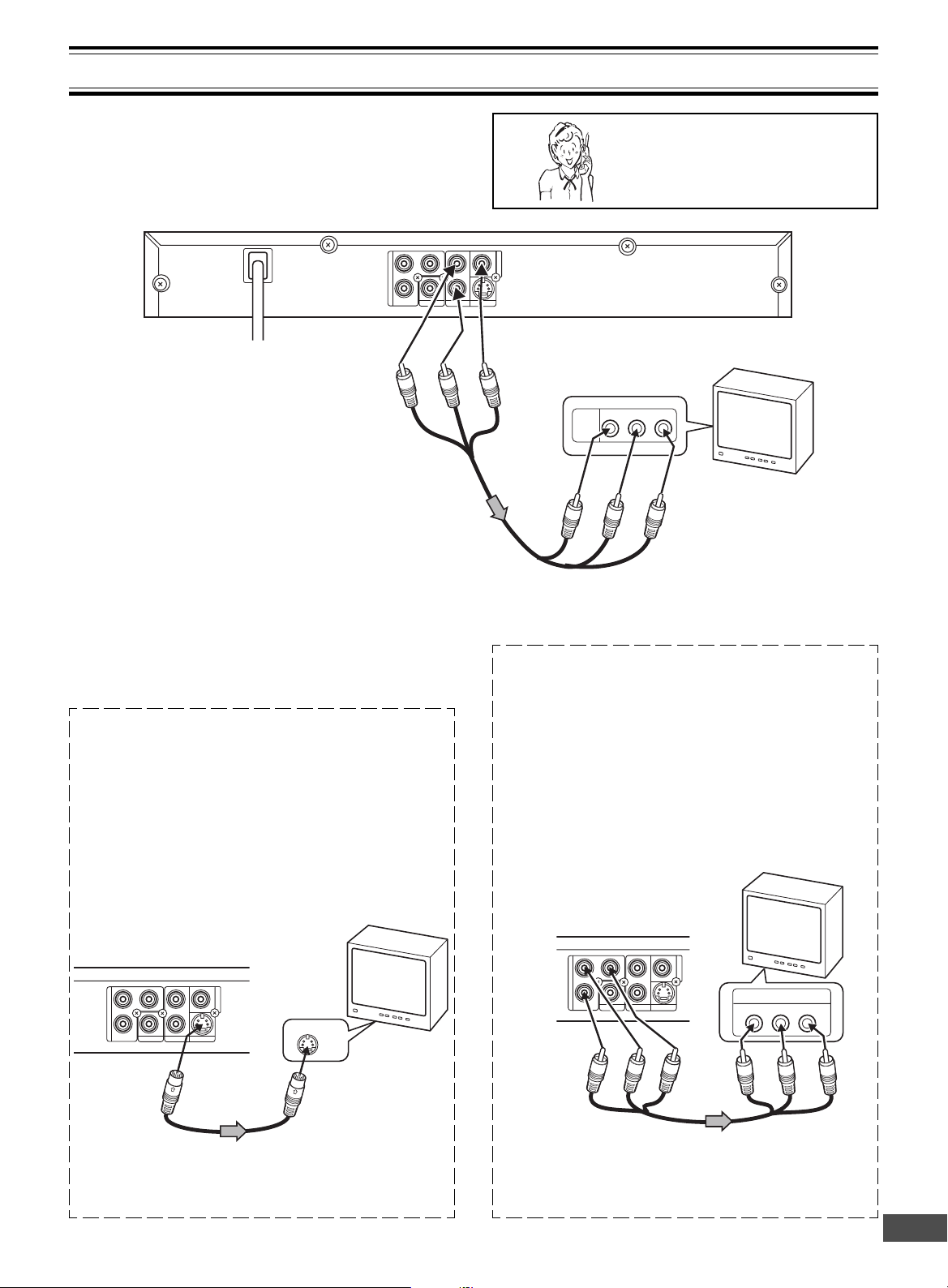
Connecting to a Conventional TV (Example 1)
Connect the DVD video player to your TV.
DVD video player
To AC 120V, 60Hz
(Red) R
(White) L
To AUDIO OUT jacks
Audio/Video cable (supplied)
Notes:
• Please refer to your TV instruction manual.
• When you connect the DVD video player to your TV, be
sure to turn off the power and disconnect both units from
the wall outlet until all the connections have been made.
• If your TV has one audio input jack, connect the AUDIO
OUT jacks of the DVD video player to a Y-cable adapter
(not supplied), then connect it to the TV Audio input. Please
consult your local audio/video dealer.
• Do not connect the DVD video player to a VCR directly.
The playback picture will be distorted because DVD video
discs are copy protected.
Using the S-VIDEO OUT jack
Note:
Please follow the steps before turn on the power.
1. If your TV has the S-video input jack, connect the DVD
video player with the S-video cable (not supplied). (The
VIDEO OUT jack connection is not necessary.)
You can enjoy clearer picture playback.
2. You also need to connect the left and right audio cables
(not supplied) to the AUDIO OUT jacks of the DVD video
player and the Audio input jacks of the TV.
Need help? Call
1-800-813-3435
To VIDEO OUT jack
(Yellow)
To audio
input jacks
(Red) R
(White) L
Using the COMPONENT VIDEO OUT jacks
Note:
Please follow the steps before turn on the power.
1. If your TV has the component video input jacks, connect the DVD video player to these jacks. (The VIDEO
OUT or S-VIDEO OUT jack connection is not
necessary.)
You can enjoy high quality picture playback.
2. You also need to connect the left and right audio cables
(not supplied) to the AUDIO OUT jacks of the DVD video
player and the Audio input jacks of the TV.
TV with Audio/Video input jacks
To video input jack
(Yellow)
TV
TV
DVD video player
COMPONENT VIEDO OUT
Pr
Pb
L
Y
COAXIAL
AUDIO OUT
S-VIDEOOUT
To S-VIDEO
OUT jack
VIDEOOUT
To S-video input jack
*S-video cable
(not supplied)
*Please consult your local audio/video dealer.
DVD video player
S-VIDEOOUT
Green
VIDEOOUT
Red
Blue
Green
COMPONENT VIEDO OUT
Pr
Pb
*Component video cable (not supplied)
Blue
Y
COAXIAL
L
AUDIO OUT
Red
-E8-
Page 10
AUDIO OUT
S-VIDEOOUT
COAXIAL
COMPONENT VIEDO OUT
Pr
Y
L
Pb
VIDEOOUT
R
34
CHANNEL
TO TV ANT. IN
R-AUDIO-LVIDEO
A/V INPUT JACKS
VHF/UHF
ANTENNA
IN
1
2
4
3
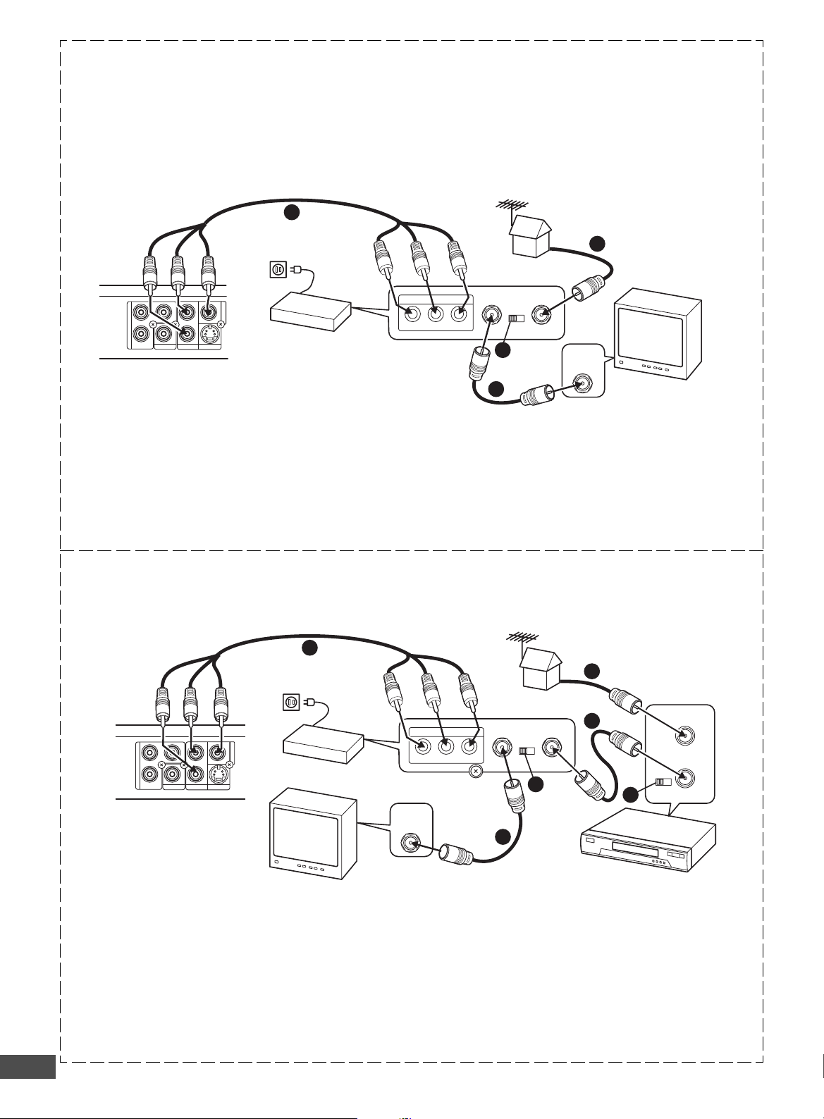
Using RF Modulator
R
34
CHANNEL
TO TV ANT. IN
R-AUDIO-LVIDEO
A/V INPUT JACKS
VHF/UHF
ANTENNA
IN
34
CHANNEL
VHF/UHF
FROM ANT.
IN
OUT
TO TV
3
1
2
5
5
4
AUDIO OUT
S-VIDEOOUT
COAXIAL
COMPONENT VIEDO OUT
VIDEOOUT
Pr
Y
L
Pb
If your TV does not have a Video input jack and has an antenna terminal only, please purchase the *RF Modulator (not
supplied).
(*Please consult your audio/video dealer.)
Example: DVD video player, TV and RF Modulator connections
Audio/Video cable (supplied)
To AUDIO
OUT jacks
To AC
120V, 60Hz
(Red) R
(White) L
To video input
jack (Yellow)
To audio input
jacks
(Red) R
(White) L
TV
To VIDEO OUT jack (Yellow)
DVD video player
1. Connect the antenna cable (not supplied) to the ANT. IN
terminal of the RF Modulator.
RF Modulator
2. Connect the 75-ohm coaxial cable (not supplied) between
4. Turn on the TV, and set the channel number (CHANNEL3
the TO TV terminal of the RF Modulator and the VHF/
UHF ANTENNA IN terminal of the TV.
3. Connect the Audio/Video cable (supplied) between the
AUDIO OUT and VIDEO OUT jacks of the DVD video
player and the AUDIO INPUT and VIDEO INPUT jacks
Note:
For more details, please refer to the instruction manual of
the RF Modulator.
of the RF Modulator.
Example: DVD video player, VCR, TV and RF Modulator connections
To AUDIO
Audio/Video cable (supplied)
To audio input
OUT jacks
To AC
120V, 60Hz
(Red) R
(White) L
To video input
jack (Yellow)
or CHANNEL4) on both TV and RF Modulator, whichever is not used for regular broadcast in your area.
jacks
(Red) R
(White) L
RF Modulator
DVD video player
To VIDEO OUT jack (Yellow)
TV
1. Connect the antenna cable (not supplied) to the VHF/
UHF FROM ANT IN terminal of the VCR.
2. Connect the 75-ohm coaxial cable (not supplied) be-
3. Connect the 75-ohm coaxial cable (not supplied) be-
tween the TO TV OUT terminal of the VCR and the ANT.
IN terminal of the RF Modulator.
tween the TO TV terminal of the RF Modulator and the
VHF/UHF ANTENNA IN terminal of the TV.
4. Connect the Audio/Video cable (supplied) between the
5. Turn on the TV, and set the channel number (CHANNEL3
Note:
For more details, please refer to the instruction manual of
the RF Modulator.
-E9-
AUDIO OUT and VIDEO OUT jacks of the DVD video
player and the AUDIO INPUT and VIDEO INPUT jacks of
the RF Modulator.
or CHANNEL4) on all TV, VCR and RF Modulator, whichever is not used for regular broadcasts in your area.
VCR
Page 11
R
COMPONENT VIDEO INPUTAUDIO INPUT
YP
B
RL P
R
AUDIO OUT
S-VIDEOOUT
COAXIAL
COMPONENT VIEDO OUT
Pr
Y
L
Pb
VIDEOOUT
Connecting to a TV with Progressive-scan Capability (Example 2)
Your TV must be capable of handing progressive scanning and have component video input capability.
To COMPENENT VIDEO
OUT jacks
DVD video player
To AC 120V, 60Hz
*Audio cable (not supplied)
(White) L
(Red) R
(Red) R
Red
To AUDIO
OUT jacks
Blue
To audio
input jacks
(White) L
*Component video cable (not supplied)
Green
To COMPONENT
VIDEO INPUT jacks
Green
Blue
Red
TV with progressive-scan
capability
*Please consult your local audio/video dealer.
1. Connect the DVD video player to the component video
input jacks of the TV. (The VIDEO OUT or S-VIDEO OUT
jack connection is not necessary.)
2. You also need to connect the left and right audio cables
(not supplied) to the AUDIO OUT jack of the DVD video
player and the Audio input jacks of the TV.
3. Set the DVD video player to the PROGRESSIVE
position. See page E15.
Progressive Scanning
While interlaced scanning produces one frame of video in
two fields, progressive scanning creates one frame in one
field.
Conventional interlaced scanning constitutes one second with
30 frames (60 fields), but progressive scanning constitutes it
with 60 frames from scratch. Progressive scanning can reproduce sharper picture with high resolution for still image or
other picture containing long texts or horizontal lines.
This model has compliance with 525p (progressive) system.
Interlaced scanning
Progressive scanning
Notes:
• Please refer to your TV instruction manual.
• When you connect the DVD video player to your TV, be
sure to turn off the power and disconnect both units from
the wall outlet until all the connections have been made.
• Do not connect the DVD video player to a VCR directly.
The playback picture will be distorted because DVD video
discs are copy protected.
Need help? Call
1-800-813-3435
-E10-
Page 12
COMPONENT VIDEO INPUT
YPBP
R
S-VIDEO IN 1
AUDIO OUT
S-VIDEOOUT
COAXIAL
COMPONENT VIEDO OUT
Pr
Y
L
Pb
VIDEOOUT
R
ADDITIONAL CONNECTION EXAMPLES
AUDIO
INPUT
R
L
R-AUDIO-L VIDEO
AUDIO
VIDEO
INPUT
1
R
AUDIO OUT
S-VIDEOOUT
COAXIAL
COMPONENT VIEDO OUT
Pr
Y
L
Pb
VIDEOOUT
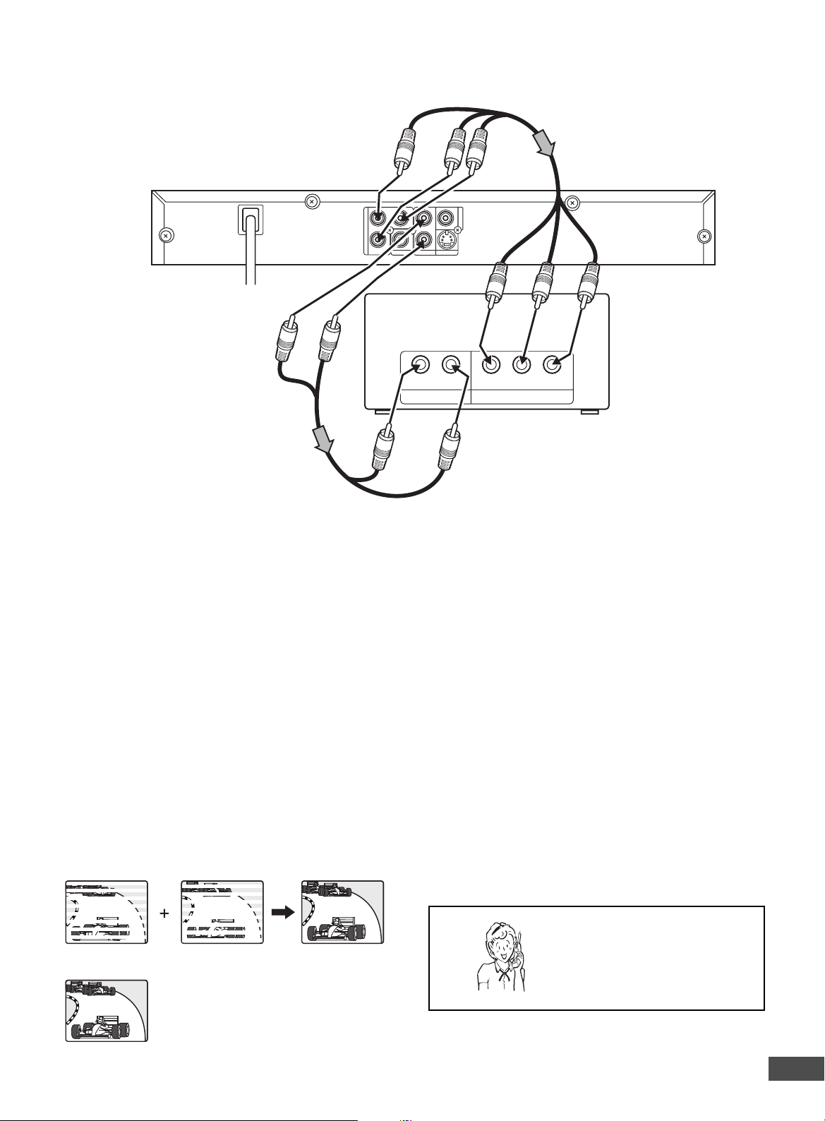
Connecting to an Audio System and TV (Example 3)
Connect the DVD video player to an Audio System and a TV.
DVD video player
To AC 120V, 60Hz
(Red) R
(White) L
To AUDIO OUT jacks
*Audio cable
(not supplied)
Notes:
• Please refer to the instruction manual of
your Audio System and TV.
• When you connect the DVD video player
to other equipment, be sure to turn off the
power and disconnect all of the equipment
from the wall outlet until all the connections have been made.
• Do not connect the DVD video player to a
VCR directly. The playback picture will be
distorted because DVD video discs are
copy protected.
Using the S-VIDEO OUT jack
Note:
Please follow the steps before turn on the power.
1. If your TV has the S-video input jack, connect the DVD
video player with the S-video cable (not supplied). (The
VIDEO OUT jack connection is not necessary.)
You can enjoy clearer picture playback.
2. You also need to connect the left and right audio cables
(not supplied) to the AUDIO OUT jacks of the DVD video
player and the Audio input jacks of the Audio System.
To VIDEO OUT jack (Yellow)
To video input (Yellow)
*Video cable (not supplied)
To audio input jacks
(White) L
(Red) R
*Please consult your local audio/video dealer.
Using the COMPONENT VIDEO OUT jacks
Note:
Please follow the steps before turn on the power.
1. If your TV has the component video input jacks, connect the DVD video player to these jacks. (The VIDEO
OUT or S-VIDEO OUT jack connection is not
necessary.)
You can enjoy high quality picture playback.
2. You also need to connect the left and right audio cables
(not supplied) to the AUDIO OUT jacks of the DVD
video player and the Audio input jacks of the Audio
System.
TV with Audio/Video input jacks
Audio System
TV
DVD video player
COMPONENT VIEDO OUT
Pr
Pb
Red
Y
COAXIAL
Blue
L
R
AUDIO OUT
Green
S-VIDEOOUT
VIDEOOUT
Blue
Green
Red
DVD video player
To S-VIDEO
OUT jack
TV
To S-video input jack
*S-video cable
(not supplied)
*Please consult your local audio/video dealer.
-E11-
*Component video cable (not supplied)
Page 13

AUDIO OUT
S-VIEDOOUT
COAXIAL
COMPONENT VIEDO OUT
VIDEOOUT
Pr
Y
L
Pb
R
Notes:
• For VIDEO connection, please refer to “BASIC CONNECTIONS”.
• Please refer to the instruction manual of your amplifier.
• When you connect the DVD video player to your amplifier, be sure to turn off the power and disconnect both units from the
wall outlet until all the connections have been made.
Connecting to an Amplifier with Dolby Digital Decoder or MPEG2 Decoder
(Example 4)
To digital audio input
*Coaxial audio cable
(not supplied)
To COAXIAL jack
Amplifier with Dolby Digital Decoder or MPEG2 Decoder
Center
speaker
Front left
speaker
COMPONENT VIEDO OUT
Pr
L
Y
VIDEOOUT
Surround left
COAXIAL
R
AUDIO OUT
S-VIDEOOUT
speaker
Pb
To enjoy Dolby Digital sound
Select “DOLBY DIGITAL BITSTREAM” in “Setting Digital Out”
on the INITIAL SETTINGS. (See page E33.)
To enjoy MPEG2 sound
Select “MPEG BITSTREAM” in “Setting Digital Out” on the
INITIAL SETTINGS. (See page E33.)
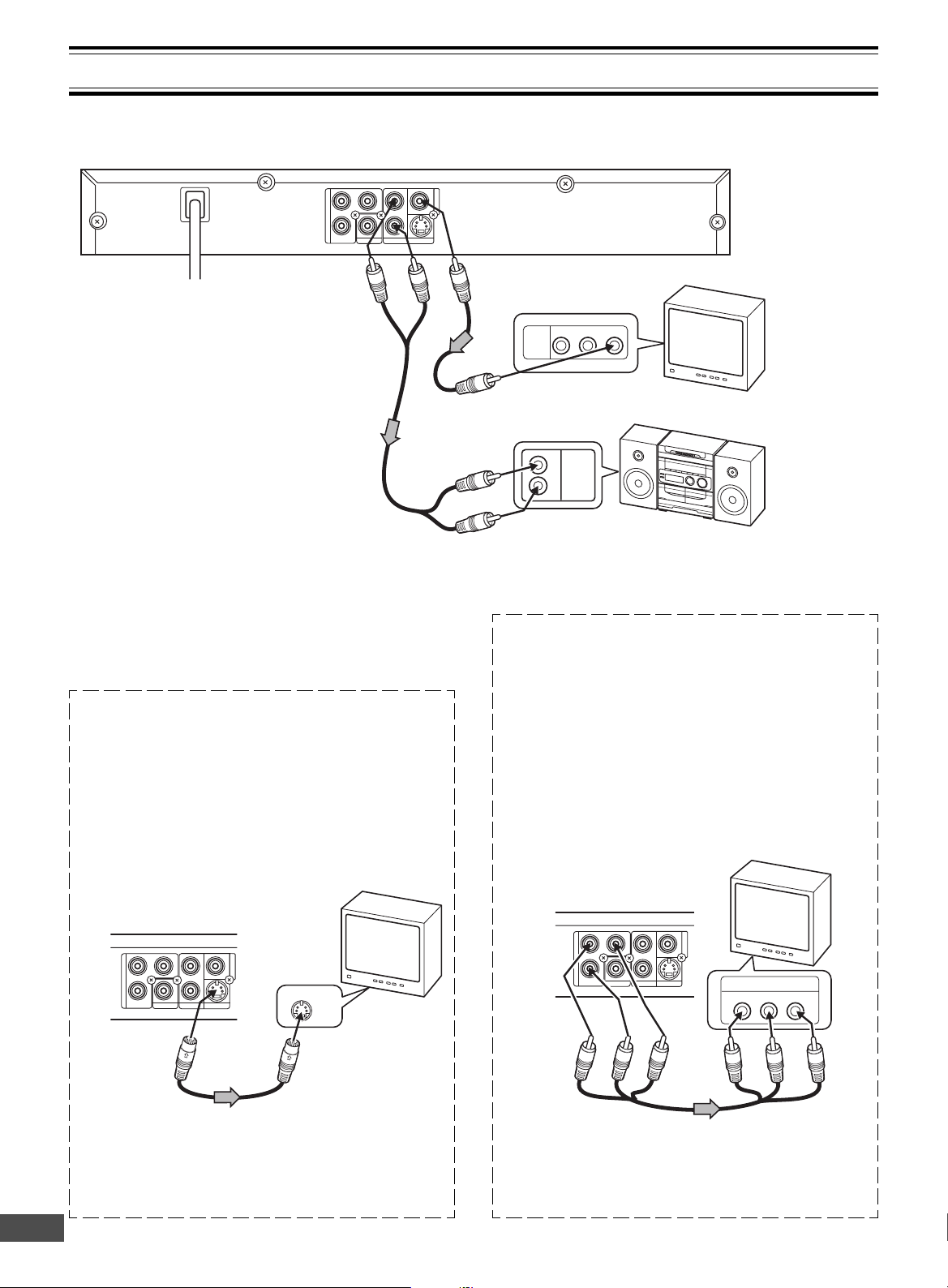
Connecting to a Digital Amplifier (Example 5)
You can enjoy 2 Channel Digital Stereo Sound.
To digital audio input
*Coaxial audio cable
(not supplied)
Front right
speaker
Subwoofer
Surround
right speaker
*Please consult your local audio/video dealer.
Manufactured under license from Dolby Laboratories.
“Dolby”, “Pro Logic” and the double-D symbol are trademarks
of Dolby Laboratories.
Amplifier with a coaxial digital input
To COAXIAL jack
To enjoy 2 Channel Digital Stereo sound
Select “DOLBY DIGITAL LPCM” and “MPEG LPCM” in “Setting Digital Out” on the INITIAL SETTINGS. (See page E33.)
Front left
speaker
-E12-
Front right
speaker
*Please consult your local audio/video dealer.
Page 14

Connecting to an Amplifier with Dolby Pro Logic Decoder (Example 6)
To AUDIO INPUT jacks
Amplifier with Dolby Pro Logic Decoder
*Audio cable
(not supplied)
To AUDIO OUT jacks
COMPONENT VIEDO OUT
Pr
Pb
Y
COAXIAL
L
R
AUDIO OUT
VIDEOOUT
S-VIDEOOUT
Front left
speaker
Surround left
speaker
Note:
Please refer to your amplifier instruction manual.
Power Supply
Connect the power cord to a 120VAC 60Hz outlet. This unit is
equipped with a polarized plug. If you have difficulty inserting
the plug, turn it over and reinsert it. If the unit will not be used
for a long time, disconnect the AC plug from the AC outlet.
Notes:
• Before connecting the power cord to an AC outlet, make
sure that all the connections have been made.
• The unit cannot be entirely disconnected from the AC
power until the power cord is unplugged from the AC outlet.
Center
speaker
Front right
speaker
Subwoofer
Surround right
speaker
*Please consult your local audio/video dealer.
CAUTION:
When connecting the DVD video player, follow the installation instruction in “IMPORTANT SAFETY INSTRUCTIONS” on page E2.
CAUTION:
TO PREVENT ELECTRIC SHOCK, MATCH WIDE
BLADE OF PLUG TO WIDE SLOT, FULLY INSERT.
ATTENTION :
POUR ÉVITER LES CHOC ÉLECTRIQUES‚
INTRODUIRE LA LAME LA PLUS LARGE DE LA
FICHE DANS LA BORNE CORRESPONDANTE DE
LA PRISE ET POUSSER JUSQU’ AU FOND.
FOR SAFE AND EFFICIENT OPERATION
• Do not damage the power cord.
• When not in use, disconnect the power cord from the
outlet. Grasp the plug, not the cord, when disconnecting
the unit.
• If water should enter the unit, electrical shock or a malfunction may result. Use in an area where there is low
humidity and little dust.
• Do not disassemble or alter the unit in any way.
• Do not use the unit in areas where extremes in temperature occur (below 40˚F (5˚C) or exceeding 95˚F (35˚C)),
or where it may be exposed to direct sunlight.
• Because of the DVD video player extremely low noise
and wide dynamic range, there is a tendency to set the
volume on the amplifier higher than necessary. Doing so
may produce an excessively high output from the amplifier which can cause damage to your speakers. Please
be careful in this regard.
• Sudden changes in the surrounding temperature can
cause dew to form on the optical pickup lens inside the
unit. Under this condition the unit may be unable to operate properly. If this should occur, remove the disc and
allow the unit to adjust to the surrounding temperature.
• When carrying the unit, be sure to remove a disc which
may be inside and turn the power off. Then unplug
the power cord from the AC outlet after 10 seconds.
Carrying the unit with a disc inside may damage the
disc and/or the unit.
• The unit is automatically set to the Screen Saver mode
after approximately 5 minutes have elapsed under the stop
or pause mode.
• The unit is automatically set to the standby mode after
approximately 30 minutes have elapsed under the complete stop mode.
• Do not install this equipment in a confined space, such as
a book case or built in cabinet.
Press [q] (or [ q OPEN/CLOSE] on the remote control)
when closing the disc tray. Do not push the disc tray.
-E13-
Page 15

PLAYABLE DISCS
The following types of discs can be played on the unit.
Disc type and logo mark
DVD-Video
Audio CD
Region Number
Region number (Regional restriction code) is built-in to the
unit and DVD video discs.
Region number “1” or “ALL” of DVD video discs can be used
on this unit.
DVD Video Disc
DVD video discs are divided into titles, and the titles are subdivided into chapters.
Title 1
Chapter 1 Chapter 2 Chapter 1 Chapter 2 Chapter 3
There are the marks on some DVD video disc packages.
Example:
Multiple languages
Multi-language subtitles
Multi-angle
Multi-aspect
Region number
Closed caption
Title 2
CAUTION:
• Only the above types of discs can be played on this unit.
DVD-ROM, CD-ROM, VCD, CVD, etc. cannot be played.
• This unit can play back the DVD-R that has recorded movie
data as well. However, some DVD-Rs cannot be played
back depending on the recording conditions.
• The DVD-R that has no movie data cannot be played back.
• This unit is to be used exclusively with the NTSC color
system. PAL system discs cannot be used with the unit.
• For MP3 CD, please see page E27.
• For Picture/JPEG CD, please see pages E29 and E30.
Handling, Storing and Cleaning Discs
• Fingerprints and dust should be carefully wiped from
the signal surface of the disc (glossy side) with a soft
cloth.
Wipe in a straight motion from the center to the outside
of the disc.
• Never use chemicals such as record cleaning sprays,
antistatic sprays or fluids, benzene or thinner to clean
the discs . These chemicals will permanently damage
the plastic surface of the disc.
• To remove a disc from its storage case, press down on
the center of the case and lift the disc out, holding it
carefully by the edges.
• Discs should be returned to their cases after use to
protect them from dust and scratches.
• To prevent warping the disc, do not expose it to direct
sunlight, high humidity or high temperatures for extended periods of time.
• Do not apply paper or write anything on either side of
the disc. Sharp writing instruments, or the inks used in
some felt-tip pens, may damage the surfaces of the
disc.
This product incorporates copyright protection technology
that is protected by method claims of certain U.S. patents
and other intellectual property rights owned by Macrovision
Corporation and other rights owners. Use of this copyright
protection technology must be authorized by Macrovision
Corporation, and is intended for home and other limited
viewing uses only unless otherwise authorized by
Macrovision Corporation.
Reverse engineering or disassembly is prohibited.
Audio CD Disc
Audio CD discs are divided into tracks.
Track 1 Track 2 Track 3 Track 4 Track 5
Need help? Call
1-800-813-3435
-E14-
Page 16

SETUP MENU
AUDIO SUBTITLE RANDOM ZOOM
PROGRAM
REV PLAY FWD
NEXTPREV
SLOW
ON OPEN/CLOSE
123
6
98
5
4
7
0
+10
zq
a
n
f
e
cd
k
STOP
VIDEO 1
BASIC OPERATION
Preparations
• Turn on the power (TV, Audio System, AV amplifier, etc.).
• Select the video input source on your television.
(Please refer to your TV instruction manual.)
TV
• Select the playback picture size according to the aspect
ratio of the TV. (For more details, see “Setting Display” on
page E32.)
4:3 LB 4:3 PS 16:9 :
(Letterbox): (Panscan):
• Select the audio input source (Audio System, AV amplifier,
etc.).
Basic Playback
Notes:
• Do not touch the disc tray while it is moving.
• Never place anything except a disc on the disc tray. Foreign objects can damage the unit.
• Do not apply excessive force to the disc tray.
• Only one disc must be placed on the disc tray at a time.
When operation buttons are pressed, that operation is displayed on the TV screen. The display turns off after several
seconds.
Disc tray
z/ON
qaz/ON
OPEN/
CLOSE
PLAY
• When you use TV with Progressive-scan capability and
connect it to the COMPONENT VIDEO OUT jacks of
the DVD video player (see page E10), you must select
the PROGRESSIVE mode. (For more details, please
refer to your TV instruction manual.)
Note:
If you use a Conventional TV, skip this section.
1. Turn on the power (TV and DVD video player).
2. In “NO DISC” mode, press and hold down [a] on the
DVD video player until “
” (PROGRESSIVE) ap-
pears briefly on the TV screen.
If you want to change the setting again, press and
hold down [a] on the DVD video player until “
(INTERLACE) appears briefly on the TV screen.
Note:
In “
” mode, the closed caption may not appear
on the TV screen.
Important Note:
• This instruction manual explains the basic instruction
of this unit using the remote control.
• Some DVD video discs have different functions that may
not be explained in this instruction manual. You may
need extra instruction. In this case, please follow the
instructions displayed on the TV screen or jacket or case
of the disc.
•“
” may appear on the TV screen during operation.
This icon means that the function is not available on the
disc now.
1. Press [z/ON].
• “SANYO” logo appears on the TV screen.
• The power indicator lights on the front panel.
2. Press [q] (or [ q OPEN/CLOSE] on the remote control).
•“q” appears on the TV screen and the disc tray opens.
• The DISC IN indicator blinks on the front panel.
Note:
To open or close the disc tray, be sure to press [q] (or
”
[ q OPEN/CLOSE] on the remote control). Do not push
back the disc tray by your hand.
3. Place the disc with the label facing up on the disc tray.
or
For 5-inch (12cm) disc For 3-inch (8cm) disc
-E15-
Page 17

TOPMENU RETURN
SETUP ME N U
AUDIO SUBTITLE RANDOM ZOOM
PROGRAM
REV PLAY FWD
NEXTPREV
SLOW
ON OPEN/CLOSE
123
6
98
5
4
7
0
+10
ENT
zq
a
n
f
e
cd
k
STOP
4. Press [q] (or [ q OPEN/CLOSE] on the remote control)
Play Movie
Languages & Audio Set-Up
Subtitles
Theatrical Trailers
Scene Selections
MENU
ENT
again.
• The disc tray closes.
Note:
Some discs may start playback automatically.
Stopping Playback
[DVD]
• Press [n STOP] (or [n] on the unit) once during playback.
“RESUME n” appears briefly on the TV screen.
The PLAY indicator blinks on the front panel.
5. Press [a PLAY] (or [a] on the unit) to start playback.
• The PLAY indicator lights on the front panel.
•“a” appears briefly on the TV screen.
Notes:
• In some discs, even if 4:3 PS is selected, the black bands
may remain on the TV screen.
• If the disc is loaded with the label side downward (and it is
a single sided disc), or if a badly scratched disc is loaded,
“NO DISC” or “NO PLAY” appears on the TV screen. If
this occurs, load the disc correctly or replace the disc.
If a disc menu screen appears on the TV screen...
TV
1. Press [4], [a], [5] or [b] (or the number buttons) to select the desired
menu.
2. Press [ENT].
Playback of the selected menu starts.
Note:
For more details, please refer to the jacket or case of the
disc.
When you press [a PLAY] (or [a] on the unit), playback
starts automatically from the point where you stopped.
“a” appears briefly on the TV screen.
Note:
Some discs may not resume playback.
• Press [n STOP] (or [n] on the unit) twice during playback.
“n” appears briefly on the TV screen and playback stops
completely.
When you press [a PLAY] (or [a]), playback starts from
the beginning of the disc.
[CD]
• Press [n STOP] (or [n] on the unit) once during playback.
The unit stops completely.
To turn off the power, press [z/ON]. The power indicator turns
off.
Note:
The unit is automatically set to the Screen Saver mode
after approximately 5 minutes have elapsed under the
stop or pause mode.
z/ON
OPEN/
CLOSE
STOP
PLAY
Note:
This handling description is printed prior to product
development. When a part of the product specification must
be changed to improve operability or other functions, priority is given to the product specification itself. In such
instances, the instruction manual may not entirely match
all the functions of the actual product.
Therefore, the actual product and packaging, as well as
the name and illustration, may differ from the manual.
Need help? Call
1-800-813-3435
-E16-
Page 18

REMOTE CONTROLLER RB-SL50
REPEAT A- B ANGLE
TOPMENU RETURN
SETUP MENU
AUDIO SUBTITLE RANDOM ZOOM
PROGRAM
123
6
98
5
4
7
0
+10
ENT
TOPMENU RETURN
SETUP M E N U
AUDIO SUBTITLE RANDOM ZOOM
PROGRAM
REV PLAY FWD
NEXTPREV
SLOW
ON OPEN/CLOSE
123
6
98
5
4
7
0
+10
ENT
zq
a
n
f
e
cd
k
STOP
Selecting a DVD Menu
Notes:
• The operation may differ depending on the disc used.
• Selecting a menu may not be possible on some discs.
1. Press [MENU].
The main menu screen will appear.
Note:
Press [MENU] again to resume playback.
Need help? Call
1-800-813-3435
2. Press [
4
], [5], [b] or [a] (or the number buttons) to se-
lect the desired menu.
3. Press [ENT].
The selected menu playback starts.
Selecting a Top Menu [DVD]
Notes:
• The operation may differ depending on the disc used.
• Selecting a top menu may not be possible on some discs.
1. Press [TOP MENU].
The top menu will appear (if the disc contains a top menu).
4
2. Press [
], [5], [b] or [a] (or the number buttons) to se-
lect the desired menu.
3. Press [ENT].
The selected menu playback starts.
Chapter (Track) Skip
ENT
TOP
MENU
MENU
4, 5
, a, b
Skipping forward
Press [NEXT e] (or e) during playback to skip to the
next chapter (or track).
“e” appears briefly on the TV screen.
A chapter (or track) is skipped each time the button is pressed.
Skipping backward
Press [PREV f] (or f) during playback to skip back to
the beginning of the previous chapter (or track).
“f” appears briefly on the TV screen.
Note:
You can skip only through the chapters, not over the title on
the DVD disc.
Important Note:
“ ” may appear on the TV screen during operation. This
icon means that the function is not available on the disc
now.
PREV
f
e
NEXT
-E17-
Page 19

SETUP MENU
AUDIO SUBTITLE RANDOM ZOOM
PROGRAM
REV PLAY FWD
NEXTPREV
123
6
98
5
4
7
0
+10
a
n
f
e
cd
STOP
Title or Chapter Search [DVD]
TOPMENU RETURN
SETUP M E N U
AUDIO SUBTITLE RANDOM ZOOM
PROGRAM
REV PLAY FWD
NEXTPREV
SLOW
ON OPEN/CLOSE
123
6
98
5
4
7
0
+10
ENT
zq
a
n
f
e
cd
k
STOP
1. Press [SEARCH MODE] once during playback or in the
stop mode.
The title/chapter search screen appears on the TV screen.
Example:
TITLE 01 / 28 CHAPTER 015 / 035
Important Note:
“ ” may appear on the TV screen during operation. This
icon means that the function is not available on the disc
now.
2. Press [a] or [b] to select “TITLE” or “CHAPTER”.
3. Press the number button(s) to enter the title or chapter
number.
Example:
To select “3”, press [3].
To select “10”, press [+10], then [0].
To select “24”, press [+10], [+10], then [4].
The title or chapter number will be changed.
Example:
TITLE 24 / 28 CHAPTER 015 / 035
4. Press [a PLAY].
Playback starts from the selected title (or chapter).
Time Search [DVD]
1. Press [SEARCH MODE] twice during playback.
The time search screen appears on the TV screen.
Example:
TITLE 01 / 02 TIME - - : - - : - -
2. Press the number button(s) to enter the time.
Example:
3 minutes 40 seconds:
Press [0], [0], [0], [3], [4], then [0].
20 minutes 5 seconds:
Press [0], [0], [2], [0], [0], then [5].
42 minutes 39 seconds:
Press [0], [0], [4], [2], [3], then [9].
1 hour 4 minutes 35 seconds:
Press [0], [1], [0], [4], [3], then [5].
SEARCH MODE
PLAY
Number
b
a
Time Search [CD]
1. Press [SEARCH MODE] once during playback.
The time search screen (TIME - - : - -) appears on the TV
screen.
2. Press the number button(s) to enter the time.
Example:
2 minutes 5 seconds:
Press [0], [2], [0], then [5].
42 minutes 39 seconds:
Press [4], [2], [3], then [9].
Playback starts from the searched time in the track.
Track Search [CD]
3. Press [a PLAY].
Playback starts from the searched time.
Note:
The Search mode may not work on some discs.
Need help? Call
1-800-813-3435
Number
MENU
Press the number buttons during playback or in the stop mode.
Example:
To select Track No.3, press [3].
To select Track No.10, press [+10], then [0].
To select Track No.24, press [+10], [+10], then [4].
Playback starts from the selected track.
-E18-
Page 20

TOPMENU RETURN
SETUP ME N U
AUDIO SUBTITLE RANDOM ZOOM
PROGRAM
REV P LAY FWD
NEXTPREV
SLOW
ON OPEN/CLOSE
123
6
98
5
4
7
0
+10
ENT
z
q
a
f
e
cd
k
STOP
n
AUDIO SUBTITLE RANDOM ZOOM
PROGRAM
REV P LAY FWD
NEXTPREV
SLOW
ON OPEN/CLOSE
123
6
98
5
4
7
0
+10
z
q
a
f
e
cd
k
STOP
n
Fast Playback
Fast forward playback
Press [FWD c] repeatedly to select the speed of the fast
forward playback.
c 1 v c 2 v c 3 v c 4 (4 steps)
Press [a PLAY] to return to normal playback.
Fast reverse playback
Press [REV d] repeatedly to select the speed of fast reverse playback.
d 1 v d 2 v d 3 v d 4 (4 steps)
Press [a PLAY] to return to normal playback.
Note:
The sound is muted during the fast playback in DVD.
Slow Motion Playback [DVD]
Press [SLOW] repeatedly to select the speed of the slow forward (or reverse) playback.
q
1 v 2 v 3 v 1 v 2 v 3
q
(Forward, 3 steps) (Reverse, 3 steps)
Press [a PLAY] to return to normal playback.
Note:
The sound is muted during the slow motion playback.
q
q
q
q
SLOW
REV
FWD
PLAY
Important Note:
“ ” may appear on the TV screen during operation.
This icon means that the function is not available on the
disc now.
Still Picture (Pause)
Press [k PAUSE/STEP] during playback.
• The PLAY indicator blinks on the front panel.
•“k” appears briefly on the TV screen.
[DVD]
Still picture mode
[CD]
Pause mode
Press [a PLAY] to return to normal playback.
Note:
The sound is muted during still picture.
Need help? Call
1-800-813-3435
PAUSE
/STEP
PLAY
Frame by Frame Advance Playback
[DVD]
Press [k PAUSE/STEP] during still picture.
•“k a” appears briefly on the TV screen.
Each time the button is pressed, the picture advances one
frame.
Press [a PLAY] to return to normal playback.
Notes:
• The sound is muted.
• Frame playback is just available in forward playback.
-E19-
Page 21

REMOTE CONTROLLER RB-SL50
REPEAT A- B ANGLE
TOPMENU RETURN
SETUP M E NU
AUDIO SUBTITLE RANDOM ZOOM
PROGRAM
98
7
0
+10
ENT
REMOTE CONTROLLER RB-SL50
REPEAT A- B ANGLE
TOPMENU RETURN
SETUP MENU
AUDIO SUBTITLE RANDOM ZOOM
PROGRAM
123
6
98
5
4
7
0
+10
ENT
a
cd
Picture Zoom [DVD]
Press [ZOOM] during playback.
The central part of the picture is magnified, and “
appears on the TV screen.
• Each time you press [ZOOM], the zoom mode will be
changed as follows:
1”
1 v 2 v 3 v OFF
• Press [4], [a], [5] or [b] to change the zoom point.
To return to the original screen, select “ OFF”.
Note:
Picture Zoom may not work on some discs.
Viewing from a Desired Camera Angle
(Multi-Angle) [DVD]
Some DVD video discs may contain scenes which have been
shot simultaneously from a number of different camera angles.
The jacket or case of discs that are recorded with angles will
be marked.
Example:
Note:
The recorded angles differ depending on the disc used.
ZOOM
4
, a, 5, b
ANGLE
1. Play the disc that is recorded with angles.
2. Press [ANGLE] repeatedly until the desired angle appears.
Example:
Important Note:
“ ” may appear on the TV screen during operation.
This icon means that the function is not available on the
disc now.
Need help? Call
1-800-813-3435
-E20-
Page 22

REMOTE CONTROLLER RB-SL50
REPEAT A - B ANGLE
TOPMENU RETURN
SETUP ME N U
AUDIO SUBTITLE RANDOM ZOOM
PROGRAM
0
+10
ENT
REMOTE CONTROLLER RB-SL50
REPEAT A - B ANGLE
TOPMENU RETURN
SETUP MENU
AUDIO SUBTITLE RANDOM ZOOM
PROGRAM
123
6
98
5
4
7
0
+10
ENT
Repeat Playback
Press [REPEAT] during playback (or programmed playback)
of the title (or track) you want to repeat.
Each time the button is pressed, the repeat mode will be
changed as follows.
[DVD]
CHAPTER:
Repeat of the chapter being played
TITLE:
Repeat of the title being played
OFF:
Normal playback mode
[CD]
T: Repeat of the track being played
ALL:
Repeat all tracks
OFF:
Normal playback mode
Designated Range Repeat Playback
(A-B Repeat)
1. Press [A-B] during playback at the beginning of the section you want to repeat (Point A).
•“ A-” appears briefly on the TV screen.
REPEAT
Point A Point B
2. Press [A-B] again at the end of the section you want to
repeat (Point B).
•“
A-B” appears briefly on the TV screen.
The section between points A and B is played repeatedly.
3. To return to normal playback, press [A-B] again.
•“
OFF ” appears briefly on the TV screen.
Note:
Repeat playback or A-B repeat playback mode may not work
correctly with some discs.
Important Note:
“ ” may appear on the TV screen during operation. This
icon means that the function is not available on the disc
now.
A-B
Need help? Call
1-800-813-3435
-E21-
Page 23

REPEAT A - B ANGLE
TOPMENU RETURN
SETUP MENU
AUDIO SUBTITLE RANDOM ZOOM
PROGRAM
REV P LAY FWD
NEXTPREV
SLOW
ON OPEN/CLOSE
123
6
98
5
4
7
0
+10
ENT
z
q
a
f
e
cd
k
STOP
n
REPEAT A - B ANGLE
TOPMENU RETURN
SETUP ME N U
AUDIO SUBTITLE RANDOM ZOOM
PROGRAM
REV P LAY FWD
NEXTPREV
SLOW
ON OPEN/CLOSE
123
6
98
5
4
7
0
+10
ENT
z
q
a
f
e
cd
k
STOP
n
Random Playback [CD]
1. Press [RANDOM] in the stop mode.
• “RANDOM ON” appears briefly on the TV screen.
2. Press [a PLAY] to start random playback.
The unit will automatically select tracks at random.
Notes:
To stop random playback, press [n STOP] and [RANDOM].
“RANDOM OFF” appears briefly.
Important Note:
“ ” may appear on the TV screen during operation.
This icon means that the function is not available on the
disc now.
Programmed Playback [CD]
Up to 32 selections can be programmed.
Programming procedure
1. Press [PROGRAM] in the stop mode.
• “PROGRAM P00:00” appears on the TV screen.
2. Press the number buttons to select the track number.
Example:
To select Track No.3, press [3].
To select Track No.10, press [+10], then [0].
To select Track No.24, press [+10], [+10], then [4].
STOP
PLAY
RANDOM
STOP
PLAY
Example:
PROGRAM P01:03
(The track No.3 is set to the first programmed number.)
3. Repeat step 2 as above to select other tracks.
Example:
PROGRAM P02:10
PROGRAM P03:24
4. Press [a PLAY] to start programmed playback.
When all programmed selections have played, the unit
stops automatically.
• The programmed contents are retained in memory. If
[a PLAY] is pressed again, programmed playback
starts.
Note:
To cancel the program, do one of the following:
• Press [n STOP] twice.
• Press [PROGRAM] in the stop mode. (“PROGRAM
P00:00” appears.)
Number
PROGRAM
Need help? Call
1-800-813-3435
-E22-
Page 24

TOPMENU RETURN
SETUP ME N U
AUDIO SUBTITLE RANDOM ZOOM
PROGRAM
REV P LAY FWD
NEXTPREV
SLOW
ON OPEN/CLOSE
123
6
98
5
4
7
0
+10
ENT
z
q
a
f
e
cd
k
STOP
n
TOPMENU RETURN
SETUP MENU
AUDIO SUBTITLE RANDOM ZOOM
PROGRAM
REV P LAY FWD
NEXTPREV
SLOW
123
6
98
5
4
7
0
+10
ENT
a
f
e
cd
k
STOP
n
Selecting Subtitle Language [DVD]
This operation works only with discs on which multiple subtitle languages are recorded.
1. Press [SUBTITLE] during playback.
The subtitle language mark appears.
(Example:
OFF” appears, press the button again.
If “
2. Press [SUBTITLE] repeatedly until the desired subtitle
language appears on the TV screen.
Example:
01/03: EN)
03/03: FR
SUBTITLE
After a few seconds, “
” disappears.
Notes:
• In some cases, the subtitle language is not changed to
the selected one.
• When a disc supporting closed caption is played, the subtitle and the closed caption may overlap each other on
the TV screen. In this case, turn the subtitle off.
• When the desired language is not selected even if the
button is pressed, the language is not available on the
disc.
• When the power is turned on or the disc is replaced, select the subtitle language again.
• If the subtitle language is not necessary, press [SUBTITLE]
to select “
OFF”.
• Please refer to “Setting Language” on page E31.
Selecting Audio Soundtrack Language
(Multi-Language) [DVD]
This operation works only with discs on which multiple audio
soundtrack languages are recorded.
1. Press [AUDIO] during playback.
2. Press [AUDIO] repeatedly until the desired language appears on the TV screen.
Examples:
01/04 DOLBY D 2CH EN
Important Note:
“ ” may appear on the TV screen during operation.
This icon means that the function is not available on the
disc now.
AUDIO
Notes:
• When the desired language is not selected even if the
button is pressed, the language is not available on the
disc.
• When the power is turned on or the disc is replaced, select the language again.
• If the language is not recorded on the disc, only the available language on the disc will be heard.
• If a DVD video disc which contains DTS is played back,
its picture is displayed on the TV screen, but its sound is
not provided.
Need help? Call
1-800-813-3435
-E23-
Page 25

REMOTE CONTROLLER RB-SL50
REPEAT A - B ANGLE
TOPMENU RETURN
SETUP ME N U
AUDIO SUBTITLE RANDOM ZOOM
ENT
Selecting On-Screen Information
Press [ON SCREEN] repeatedly to show the disc information
(Title, Chapter, Title elapsed playing time, Language, etc.).
For improvement, on-screen displays subject to
change without notice.
Example for DVD:
1. Press [ON SCREEN] during playback.
Title remaining playing time
Title elapsed playing time
Title number Chapter number
DVD 00:08:40 00:00:23
TITLE 01/02 CHAPTER 03/35 01/03
AUDIO 01/04 DOLBY D 5.1CH EN
SUBTITLE 01/03 EN
Camera angle
Subtitle language Audio type
2. Press [ON SCREEN] again.
Title elapsed playing time
00:08:40
Example for CD:
1. Press [ON SCREEN] during playback.
Track elapsed playing time
CD
00:02:23
TRACK 01/12
2. Press [ON SCREEN] again.
Track elapsed playing time
00:02:24
3. Press [ON SCREEN] to close the disc information.
3. Press [ON SCREEN] to close the disc information.
ON SCREEN
Important Note:
“ ” may appear on the TV screen during operation. This
icon means that the function is not available on the disc
now.
Need help? Call
1-800-813-3435
-E24-
Page 26

REPEAT A - B ANGLE
TOPMENU RETURN
SETUP MENU
AUDIO SUBTITLE RANDOM ZOOM
PROGRAM
REV P LAY FWD
NEXTPREV
SLOW
123
6
98
5
4
7
0
+10
ENT
a
f
e
cd
k
STOP
n
TVGuardian® OPERATION
Before Setting
• Initial setting is “CC2” on this unit.
• Please set “CC2” or “C2” (Closed caption on channel 2)
on your TV first. For more details, please refer to your TV
instruction manual.
• When “TVG MODE” is set, the subtitle language may not
appear.
Setting TVGuardian
1. Press [SETUP] in the stop mode.
“SETUP” screen appears.
2. Press [5] to select “TVG”.
3. Press [ENT].
“TVG” screen appears.
®
SETUP
LANGUAGE
DISPLAY
DIGITAL OUT
PARENTAL
TVG
In this instruction manual, the language in on-screen
display is English. If you change the language (see
page E31), please follow the selected language in onscreen display.
Number
SETUP
ENT
4, a, 5, b
8. Press [ENT].
The submenu is set.
“TVG” screen returns.
9. Press [b] to skip back to “TVG MODE”.
TVG
TVG MODE
DAMN/HELL
RELIGIOUS
SEXUAL REFERENCE
OFF
TOLERANT
MODERATE
STRICT
TVG CC MODE
TVG CC CH
MAIN MENU
4. Press [a] to select the submenu of “TVG MODE”.
5. Press [5] or [4] to select the submenu.
OFF:
TVG doesn’t operate.
TOLERANT:
Only the most offensive foul language will be filtered.
MODERATE:
More offensive foul language will be filtered.
STRICT:
All the foul language will be filtered.
6. Press [ENT].
The password confirmation screen appears.
7. Enter the password in the box.
(For more details, please refer to “Setting Parental”
on page E34.)
10.Repeat steps 2 - 9 to set other items (“DAMN/HELL”,
“RELIGIOUS”, “SEXUAL REFERENCE”, “TVG CC
MODE” and “TVG CC CH”).
Note on the submenu of “TVG CC MODE”
OFF:
No closed caption.
ON MUTE:
Display the modified text only.
ALWAYS:
Display all text with the modified text.
Note:
Set “TVG CC CH” to “CC2”.
11. Press [SETUP] to close the screen.
Note:
To return to the “SETUP” screen, press [5] to select “MAIN
MENU”, and press [ENT].
Need help? Call
1-800-813-3435
-E25-
Page 27

How It Works After Setting TVGuardian®:
When a disc supporting closed caption is played, it mutes the
entire phrase instead of just the swear word and displays the
modified text, by design. It turns the sound back on when the
phrase is completed.
Examples:
The phrase “Get the hell out”, is muted and “Get Out.”, is
displayed.
The phrase “Move you’re a !”, is muted and “Move your tail!”,
is displayed.
IMPORTANT INFORMATION:
• Use a TV with closed caption capability and set the
function to “On”.
• Set the same channel number on your TV as above.
• The built-in TVGuardian® Foul Language Filter (TVG®)
works only English language DVD video disc supporting closed caption, not any other languages.
• For improvement, on-screen displays subject to
change without notice.
Notes:
• Foul word that are normally filtered are missed when
closed-captioning errors exist (i.e. a foul word is not
captioned, misspelled or is not synchronized with the spoken word.)
• The built-in Foul Language Filter may not work on some
discs depending on recording conditions.
• DVD video discs may or may not respond to the TVG
Mode settings. Make sure this function works with your
DVD video discs.
• If you want to see the original closed caption, set “TVG
MODE” to “OFF”.
®
TVGuardian
ciple Solutions, Inc.
and TVG® are registered trademarks of Prin-
-E26-
Need help? Call
1-800-813-3435
Page 28

TOPMENU RETURN
SETUP MENU
AUDIO SUBTITLE RANDOM ZOOM
PROGRAM
REV P LAY FWD
NEXTPREV
SLOW
123
6
98
5
4
7
0
+10
ENT
z
q
a
f
e
cd
k
STOP
n
MP3 CD OPERATION
Before Starting
This unit can play back the CD that has recorded music data,
MP3 files.
• The file system is ISO9660 Level 1 and Level 2.
• If the CD has both audio CD tracks and MP3 files, only
audio CD tracks are played.
• It may take 30 seconds or more for this unit to read MP3
files. It depends on its structure.
• This unit can recognize up to 256 files or folders per disc.
The CD with 257 files or folders and over is not available
to this unit.
• MP3 CDs may not be played in the recorded order.
1. Please use the MP3 software with the function that
can record data alphabetically or numerically.
2. Please avoid making many sub-folders by preference
However, some CD-R/RWs cannot be played back depending on the recording conditions.
Before playing back MP3 files, please read the following.
MP3 CD
• MP3 files must have the extension letters, “.MP3” or
“.mp3”.
• Standard, sampling frequency, and the bit rate:
MPEG-1 Audio
32kHz, 44.1kHz, 48kHz
32kbps ~ 320kbps (constant bit rate or variable bit rate)
• The recommended recording setting for a high-quality
sound is 44.1kHz of sampling frequency and 128kbps of
constant bit rate.
LIMITATIONS ON DISPLAY
Available letters for display are the following: capital or small
alphabets of A through Z, and numbers of 0 through 9.
CAUTION:
• Some MP3 CDs cannot be played back depending on the
recording conditions.
• The CD has no music data or non-MP3 files cannot be
played back.
• The WMA files cannot be played back.
MP3 CD Playback
STOP
Number
.
ENT
1. Load the disc with the label facing up on the disc tray.
(Please refer to “BASIC OPERATION” on page E15.)
• “FILE” screen appears.
Note:
Some discs may start playback automatically.
2. To select the folder or file, do one of the following:
• Press the number button(s).
Example:
To select No.3, press [3].
To select No.10, press [+10], then [0].
To select No.24, press [+10], [+10], then [4].
• Press [4], [a], [b] or [b] to select the folder or file,
and press [ENT].
• The file menu of the selected folder appears.
• If the file is selected, the selected file playback starts.
3. Repeat step 2 to select the file in the file menu.
Playback starts.
4, a, 5, b
Note:
If the disc is loaded with the label side downward, or if a badly
scratched disc is loaded, “NO DISC” or “NO PLAY” appears
on the TV screen. If this occurs, load the disc correctly or
replace the disc.
Stopping Playback
Press [n STOP] during playback.
Need help? Call
1-800-813-3435
-E27-
Page 29

REMOTE CONTROLLER RB-SL50
REPEAT A - B ANGLE
TOPMENU RETURN
SETUP ME N U
AUD IO SUBTITLE RANDOM ZOOM
PROGRAM
REV P LAY FWD
NEXTPREV
SLOW
ON OPEN/CLOSE
123
6
98
5
4
7
0
+10
ENT
z
q
a
f
e
cd
k
STOP
n
Pause
Press [k PAUSE/STEP] during playback.
•“k” appears on the TV screen.
• The PLAY indicator blinks on the unit.
Note:
The sound is muted.
The [a PLAY] to return to normal playback.
File Skip
Skipping forward
Press [NEXT e] during playback to skip to the next file.
“e” appears briefly on the TV screen.
Skipping backward
Press [PREV f] during playback to skip back to the beginning of the previous file.
“f” appears briefly on the TV screen.
PREV
STOP
PAUSE
/STEP
NEXT
PLAY
Repeat Playback
Press [REPEAT] during playback.
Each time the button is pressed, the repeat mode will be
changed as follows:
T: Repeat of the file being played
FOLDER: Repeat all files in the folder
ALL: Repeat all files (and all JPEG)
OFF: Normal playback mode
To Check the Elapsed Playing Time
Press [ON SCREEN] during playback.
• The current file elapsed playing time appears.
Press the button again to turn if off.
Important Note:
“ ” may appear on the TV screen during operation. This
icon means that the function is not available on the disc
now.
REPEAT
ON SCREEN
Need help? Call
1-800-813-3435
-E28-
Page 30

REPEAT A - B ANGLE
TOPMENU RETURN
SETUP MENU
AUDIO SUBTITLE RANDOM ZOOM
PROGRAM
REV P LAY FWD
NEXTPREV
SLOW
ON OPEN/CLOSE
123
6
98
5
4
7
0
+10
ENT
z
q
a
f
e
cd
k
STOP
n
PICTURE DISC OPERATION
f
e
KODAK Picture CD Playback
With KODAK Picture CD, it’s easy to turn film into pictures
you can email from your PC and view on this DVD video player!
Just bring your film in for processing, and check the box for
KODAK Picture CD. You’ll get back your prints and negatives
as usual - plus you’ll get a special CD that contains your pictures along with software that lets you view, enhance, share,
and print your pictures from your computer and view them on
this DVD video player.
PREV
STOP
4, a, 5, b
1. Load the disc with the label facing up on the disc tray.
(Please refer to “BASIC OPERATION” on page E15.)
• The first thumbnail pictures (maximum 9-picture) ap-
pear on the TV screen.
Example:
PAUSE
/STEP
NEXT
PLAY
ENT
2. Press [4], [a], [5] or [b] to move the cursor to the desired picture.
• To go to the next or previous thumbnail pictures, press
[NEXT e] or [PREV f].
3. Press [ENT] (or [a PLAY]) to start the slide show from the
selected picture.
• If you press [k PAUSE/STEP] during the slide show,
the slide show stops temporarily. “k” appears briefly.
Press [a PLAY] (or [NEXT e]) again to resume the
slide show.
• If the picture appears upside down, sideways, etc...
Press [4], [a], [5] or [b] as follows:
a: Rotate it 90 degrees clockwise.
b: Rotate it 90 degrees counterclockwise.
4: Change it to the mirrored image picture upside
down.
5: Change it to the mirrored right-and-left reversed
image picture.
• If you press [NEXT e] or [PREV f], during the
slide show, it skips to the next picture or previous
picture.
After the last picture has displayed, the last thumbnail pictures appear.
• To stop the slide show, press [n STOP]. The thumb-
nail pictures appear.
Notes:
• If the disc is loaded with the label side downward, or if a
badly scratched disc is loaded, “NO DISC” or “NO PLAY”
appears on the TV screen. If this occurs, load the disc
correctly or replace the disc.
• The file system is ISO9660 Level 1 and Level 2.
• This unit can recognize up to 256 files or folders per disc.
The CD with 257 files or folders and over is not available
to this unit.
• FUJICOLOR CD can be used.
• Some discs cannot be played back depending on the recording conditions.
• It may take 30 seconds or more for this unit to read KODAK
Picture CDs. It depends on its structure.
Need help? Call
1-800-813-3435
KODAK and Picture CD are registered trademarks of Eastman
Kodak company.
-E29-
Page 31

TOPMENU RETURN
SETUP ME N U
AUD IO SUBTITLE RANDOM ZOOM
PROGRAM
REV P LAY FWD
NEXTPREV
SLOW
ON OPEN/CLOSE
123
6
98
5
4
7
0
+10
ENT
z
q
a
f
e
cd
k
STOP
n
JPEG CD Playback
You can also view digital images from JPEG files on disc created by your computer.
• It would take 30 seconds or more for this unit to read the
JPEG files depending on its structure.
• Some JPEG files cannot be played back depending on
the recording conditions.
1. Load the disc with the label facing up on the disc tray.
(Please refer to “BASIC OPERATION” on page E15.)
• “FILE” screen appears.
Note:
Some discs may start the side show automatically.
2. To select the file, do one of the following:
• Press the number button(s).
Example:
To select No.3, press [3].
To select No.10, press [+10], then [0].
To select No.24, press [+10], [+10], then [4].
• Press [4], [a], [5] or [b] to select the file, and press
[ENT].
The slide show starts.
If the picture appears upside down, sideways, etc...
Press [4], [a], [5] or [b] as follows:
a: Rotate it 90 degrees clockwise.
b: Rotate it 90 degrees counterclockwise.
4: Change it to the mirrored image picture upside down.
5: Change it to the mirrored right-and-left reversed
image picture.
Picture Zoom
1. Press [k PAUSE/STEP] at the desired picture (KODAK
Picture CD or JPEG CD).
2. Press [ZOOM] to select “ ”.
3. Press [FWD c] or [REV d] to select the desired picture size.
• To return to the original size, select “
• Press [a PLAY] to resume the slide show.
REV
PLAY
Number
OFF”.
PAUSE
/STEP
STOP
FWD
ZOOM
ENT
4, a, 5, b
Notes:
• To stop the slide show, press [n STOP].
• If the disc is loaded with the label side downward, or if a
badly scratched disc is loaded, “NO DISC” or “NO PLAY”
appears on the TV screen. If this occurs, load the disc
correctly or replace the disc.
• The file system is ISO9660 Level 1 and Level 2.
• This unit can recognize up to 256 files or folders per disc.
The CD with 257 files or folders and over is not available
to this unit.
• JPEG resolution is up to 5120 x 3840.
• Some discs cannot be played back depending on the recording conditions.
• If you press [NEXT e] or [PREV f] during the slide
show, it skips to the next picture or previous picture.
Important Note:
“ ” may appear on the TV screen during operation. This
icon means that the function is not available on the disc
now.
If the disc is mixed with MP3 and JPEG files...
The files will be played back in alphabetical order.
Need help? Call
1-800-813-3435
-E30-
Page 32

REPEAT A - B ANGLE
TOPMENU RETURN
SETUP ME N U
AUDIO SUBTITLE RANDOM ZOOM
PROGRAM
123
6
98
5
4
7
0
+10
ENT
INITIAL SETTINGS
Once the initial settings have been completed, the unit can
always be operated under the same conditions.
The settings will be retained in the memory until they are
changed, even if the power is turned off.
Setting Language
1. Press [SETUP] in the stop mode.
“SETUP” screen appears.
“LANGUAGE” is highlighted.
SETUP
LANGUAGE
DISPLAY
DIGITAL OUT
PARENTAL
TVG
2. Press [ENT].
“LANGUAGE” screen appears.
“OSD (on-screen display)” is highlighted.
LANGUAGE
Notes:
• In this instruction manual, the language in on-
screen display is English.
If you change the language, please follow the selected language in on-screen display.
• You cannot switch audio sound track languages if there
is only one language recorded on the disc.
• When you play back a DVD video disc, the unit automatically displays the pre-selected subtitle language if
it is included on the disc.
• For improvement, on-screen displays subject to
change without notice.
• This handling description is printed prior to product
development.
When a part of the product specification must be
changed to improve operability or other functions, priority is given to the product specification itself. In such
instances, the instruction manual may not entirely
match all the functions of the actual product.
Therefore, the actual product and packaging, as well
as the name and illustration, may differ from the manual.
OSD
AUDIO
SUBTITLE
DVD MENU
ENGLISH
ESPAÑOL
FRANÇAIS
DEUTSCH
PORTUGUES
MAIN MENU
3. Press [a] to select the submenu of “OSD”.
4. Press [5] or [4] to select the language (highlighted).
5. Press [ENT].
The OSD language is set.
(In this example, “OSD” is English.)
LANGUAGE
OSD
AUDIO
SUBTITLE
DVD MENU
MAIN MENU
ENGLISH
ESPAÑOL
FRANÇAIS
DEUTSCH
PORTUGUES
SETUP
4, a, 5, b
ENT
6. Press [b] to skip back to “OSD”.
7. Press [5] to select “AUDIO”.
The sub menu (“DISC”, “ENGLISH”, “SPANISH”,
“FRENCH”, “GERMAN” and “PORTUGUESE”) appears.
8. Press [a] to select the submenu of “AUDIO”.
9. Press [5] or [4] to select the language (highlighted).
10. Press [ENT].
The AUDIO language is set.
11. Press [b] to skip back to “AUDIO”.
12. Repeat steps 7 ~ 11 to set “SUBTITLE” and “DVD MENU”.
13. Press [SETUP] to close the screen.
Note:
To return to the “SETUP” screen, press [5] to select “MAIN
MENU”, and press [ENT].
-E31-
Page 33

REPEAT A - B ANGLE
TOPMENU RETURN
SETUP MENU
AUDIO SUBTITLE RANDOM ZOOM
PROGRAM
REV P LAY FWD
123
6
98
5
4
7
0
+10
ENT
a
cd
Setting Display
1. Press [SETUP] in the stop mode.
“SETUP” screen appears.
SETUP
LANGUAGE
DISPLAY
DIGITAL OUT
PARENTAL
TVG
2. Press [5] to select “DISPLAY”.
SETUP
4, a, 5, b
ENT
3. Press [ENT].
“DISPLAY” screen appears.
DISPLAY
TV TYPE
4 : 3 LB
4 : 3 PS
MAIN MENU
16 : 9
4. Press [a] to select the submenu of “TV TYPE”.
5. Press [5] or [4] to select the appropriate setting for your
TV screen size (“4:3 LB”, “4:3 PS” or “16:9”).
4:3 LB (Letterbox):
Select when a conventional TV set
is connected.
When the wide screen disc is played
back, the black bands appear at the
top and bottom of screen.
4:3 PS (Panscan):
Select when a conventional TV set
is connected.
When the wide screen disc is played
back, it displays pictures cropped to
fill to your TV screen. The left and
Cut off Cut off
right edges are cut off.
6. Press [ENT].
The TV type is set.
7. Press [b] to skip back to “TV TYPE”.
8. Press [SETUP] to close the screen.
Note:
To return to the “SETUP” screen, press [5] to select “MAIN
MENU”, and press [ENT].
16:9 :
Select when a wide screen TV set
is connected.
Played in “FULL” size. (Setting the
wide screen TV to “FULL” mode is
also necessary.)
Notes:
• The screen size may differ depending on the DVD
• If you select 16:9 to get rid of the black bands on screen
• In some discs, even if 4:3 PS is selected, the black
video discs.
when wide screen disc is played back, picture may be
slightly distorted.
bands may remain on the screen.
Need help? Call
1-800-813-3435
-E32-
Page 34

Setting Digital Out
REPEAT A - B ANGLE
TOPMENU RETURN
SETUP MENU
AUDIO SUBTITLE RANDOM ZOOM
PROGRAM
123
6
98
5
4
7
0
+10
ENT
If the COAXIAL (Coaxial digital output) jack is connected to
the amplifier, you must set as follows:
7. Press [b] to skip back to “DOLBY DIGITAL”.
8. Repeat steps 2 - 7 to set other items (“MPEG” and “96kHz
LPCM” ).
MPEG (Moving Picture Expert Group):
If your amplifier has MPEG2 Decoder, select
“BITSTREAM”. If not, select “LPCM”.
SETUP
1. Press [SETUP] in the stop mode.
“SETUP” screen appears.
SETUP
LANGUAGE
DISPLAY
DIGITAL OUT
PARENTAL
TVG
2. Press [5] to select “DIGITAL OUT”.
3. Press [ENT].
“DIGITAL OUT” screen appears.
4, a, 5, b
ENT
96kHz LPCM (96kHz Liner Pulse Code Modulation):
If your amplifier is available for 96kHz sampling, select
“96kHz LPCM”. If not, select “48kHz LPCM”.
Notes:
• When “48kHz LPCM” is set, 48kHz LPCM audio
signals are provided from the AUDIO OUT jacks,
not 96kHz LPCM audio signals.
• When playing back the DVD video disc which recorded with 96kHz LPCM, there is no digital output.
• However playing back the DVD video disc with no
copyright protection, the sound is original recorded
sound.
9. Press [SETUP] to close the screen.
Note:
To return to the “SETUP” screen, press [5] to select “MAIN
MENU”, and press [ENT].
DIGITAL OUT
DOLBY DIGITAL
MPEG
LPCM
BITSTREAM
96kHz LPCM
MAIN MENU
4. Press [a] to select the submenu.
5. Press [5] or [4] to select “LPCM” or “BITSTREAM”.
DOLBY DIGITAL:
If your amplifier has Dolby Digital Decoder, select
“BITSTREAM”. If not, select “LPCM”.
6. Press [ENT].
The submenu is set.
Need help? Call
1-800-813-3435
-E33-
Page 35

Setting Parental
REPEAT A - B ANGLE
TOPMENU RETURN
SETUP MENU
AUDIO SUBTITLE RANDOM ZOOM
PROGRAM
123
6
98
5
4
7
0
+10
ENT
Note:
The PASSWORD is set to “0000” before shipping from the
factory.
1. Press [SETUP] in the stop mode.
“SETUP” screen appears.
2. Press [5] to select “PARENTAL”.
3. Press [ENT].
“PARENTAL” screen appears.
Number
SETUP
4, a, 5, b
ENT
PARENTAL
PASSWORD
CHANGE
LEVEL
MAIN MENU
4. Press [a] to select “CHANGE”.
5. Press [ENT].
“PASSWORD CHANGE” screen appears.
6. Press the number buttons to enter the 4 digits password
in “OLD PASSWORD”.
“NEW PASSWORD” is highlighted.
Note:
If you change the password for the first time, enter [0], [0],
[0] and [0].
Because the initial password is set to “0000” before shipping from the factory.
If [RETURN] is pressed, “PARENTAL” screen returns.
7. Press the number buttons to enter a new 4 digits password in “NEW PASSWORD”.
15. Enter the same password in the box.
16. Press [ENT].
The parental lock level is set.
“PARENTAL” screen returns.
17. Press [b] to skip back to “LEVEL”.
18. Press [SETUP] to close the screen.
Note:
To return to the “SETUP” screen, press [5] to select “MAIN
MENU”, and press [ENT].
Parental Control
MPAA (Motion Picture Association of America) Guideline
is a rating system that provides advanced cautionary information to parent about the content of movie programs.
The parental lock level is equivalent to the following MPAA
Rating System.
Level 8: Adult
Level 7: NC-17 (No one 17 and under admitted)
Level 6: R (Restricted)
Level 4: PG-13 (Parents strongly cautioned)
Level 3: PG (Parental guidance suggested)
Level 1: G (General audiences)
“CONFIRM” is highlighted.
8. Enter the same password in “CONFIRM”.
9. Press [ENT].
The password is set.
“PARENTAL” screen returns.
10. Press [b] to skip back to “PASSWORD”.
11. Press [5] to select “LEVEL”.
The submenu appears.
12. Press [a] to select the submenu of “LEVEL”.
13. Press [5] or [4] to select the parental lock level (“OFF” ~
“8”).
14. Press [ENT].
The password confirmation screen appears.
Note:
If [RETURN] is pressed, “PARENTAL” screen returns.
Some DVD discs contain a restriction level which enables
parents to prevent playback of discs by children. This unit
is equipped with a password designed to prevent children
changing the level.
You cannot play DVD video discs rated higher than the
level you selected unless you cancel the parental lock
function.
For example, when you select level “5”, the unit will not
play discs with ratings of “6”, “7” or “8”.
The information will appear on the TV screen.
If you forget the password...
In “NO DISC” mode, enter the “PARENTAL” menu, enter
[+10], [+10], [+10], [+10], even if 4 digits “XXXX” appears.
See the left column to set the password and parental lock
level again.
Note:
DVD video discs may or may not respond to the parental
lock settings. Make sure this function works with your DVD
video discs.
-E34-
Page 36

TROUBLESHOOTING GUIDE
If you have followed the instructions and are having difficulty operating the unit, locate the SYMPTOM in the left column below.
Check the corresponding POSSIBLE CAUSE and CORRECTIVE ACTION columns to locate and remedy the problem.
SYMPTOM
No power.
The power is on, but the player does not work.
No picture.
No sound.
The playback picture is poor.
“ ” appears on the TV screen.
POSSIBLE CAUSE
No power plug connection at the AC wall outlet.
No disc is loaded.
An unplayable disc is loaded.
The TV is not set to receive signal from the
player.
The video cable is not connected.
The S-video cable is not connected.
“PROGRESSIVE” mode is set.
The TV is turned off.
The audio cables are not connected.
The audio equipment is turned off.
An unplayable disc is loaded.
The selected function does not operate on the
disc now.
CORRECTIVE ACTION
Insert the power plug into the AC wall outlet.
Load a disc.
Load a playable disc. (Check the disc logo,
type, color system and region number. See
page E14.)
Select the correct input function on the TV.
Connect the video cable into the jack.
Connect the video cable into the jack.
Select “INTERLACE” mode. (See page E15.)
Turn on the TV.
Connect the audio cables into the jacks.
Turn on the audio equipment connected with
the audio cable.
Load a playable disc. (Check the disc logo,
type, color system and region number. See
page E14.)
The feature or action cannot be completed at
this time because:
• The feature is not available at the moment.
• The DVD software restricts it.
• The DVD software doesn’t support the feature (e.g., angles).
The unit does not start playback.
“NO PLAY” appears on the TV screen.
No disc is loaded.
An unplayable disc is loaded.
The disc is loaded with the label side down.
The disc is dirty.
“PARENTAL” is set.
An unplayable disc is loaded.
“PARENTAL” is set.
The disc may not have the correct file or data.
Load a disc.
Load a playable disc. (Check the disc logo,
type, color system and region number. See
page E14.)
Load the disc on the disc tray correctly.
Clean the disc or replace it. (See page E14.)
Cancel the parental lock function or change
the rating level. Reset it after play. (See page
E34.)
Load a playable disc. (Check the disc logo,
type, color system and region number. See
page E14.)
Cancel the parental lock function or change
the rating level. Reset it after play. (See page
E34.)
Load a playable disc.
Need help? Call
1-800-813-3435
-E35-
Page 37

SYMPTOM
POSSIBLE CAUSE
CORRECTIVE ACTION
The operation or display is not normal.
The remote control does not work properly.
The unit must be reset.
The batteries in the remote control are weak,
or installed incorrectly.
The remote control is not aimed at the remote sensor window.
1. Disconnect the power cord.
2. Reconnect the power cord.
3. Resume operation.
Check the battery polarity (+ or –).
Replace the batteries. (See page E6.)
Aim the remote control at the remote sensor
window. (See page E6.)
SERVICING:
Should this product require service, refer to the SANYO DVD limited warranty.
If you do not have a convenient SANYO service station nearby, contact the SANYO dealer where you purchased the unit. Be
sure to give the model number and explain the problem. The dealer will advise you how to obtain service.
MAINTENANCE
WARNING:
FOR YOUR PERSONAL SAFETY, BE SURE TO DISCONNECT THE AC POWER CORD BEFORE PROCEEDING WITH ANY MAINTENANCE OR CLEANING.
Cleaning the cabinet
Use a clean soft cloth moistened with plain lukewarm water
and wrung dry. Never use benzol, benzene or other strong
chemical cleaners since these could damage the finish of your
unit. It is important that no liquid reaches the inside of the
unit.
SPECIFICATIONS
Type:
DVD Video player
Signal format:
NTSC color
Laser:
Semiconductor laser, wavelength 650 nm/790 nm
Frequency range (digital audio):
4 Hz to 44 kHz (DVD fs: 96 kHz)
Signal to noise ratio:
More than 96 dB
Harmonic distortion (digital audio):
0.01 %
Wow and flutter:
Below measurable level
Outputs:
S-VIDEO OUT:
Y: 1.0 V
C: 0.286 V
(75 Ω)
p-p
p-p
(75 Ω)
COMPONENT VIDEO OUT:
Y: 1.0 V
P
b
: 0.7 V
P
r
: 0.7 V
(75 Ω)
p-p
(75 Ω)
p-p
(75 Ω)
p-p
AUDIO OUT:
2 V rms
VIDEO OUT:
1.0 V
(75 Ω)
p-p
COAXIAL:
Coaxial digital output
Power requirements:
AC 120 V, 60 Hz
Power consumption:
11 Watts
Dimensions (W x H x D):
Approx. 14.2" x 2" x 9.5" (360 x 50.5 x 237 mm)
Weight:
Approx. 3.5 lbs (1.6 kg)
IMPORTANT INFORMATION
Because its products are subject to continuous improvement, SANYO reserves the right to modify product designs and specifications
without notice and without incurring any obligation.
-E36-
Page 38

For assistance in obtaining repairs and operational information, please contact the following Toll Free Number:
DIAL TOLL FREE: 1-800-813-3435
Weekdays: 7:30 AM - 4:00 PM Central Time
Also, you may write to SANYO Manufacturing Corporation, 3333 Sanyo Road, Forrest City, Arkansas 72335.
Limited Warranty
LABOR 90 DAYS PARTS 1 YEAR CARRY-IN ONLY
THIS WARRANTY IS VALID ONLY ON SANYO PRODUCTS PURCHASED FROM A WAL-MART STORE AND
USED IN THE UNITED STATES OF AMERICA AND PUERTO RICO, EXCLUDING THE UNITED STATES’ OTHER TERRITORIES AND PROTECTORATES. THIS WARRANTY APPLIES ONLY TO THE ORIGINAL RETAIL PURCHASER AND
DOES NOT APPLY TO PRODUCTS USED FOR ANY INDUSTRIAL, PROFESSIONAL OR COMMERCIAL PURPOSE.
Subject to the OBLIGATIONS and EXCLUSIONS below, SANYO Manufacturing Corporation (“SANYO”) warrants this SANYO product against defects in materials and workmanship for the periods of LABOR and PARTS specified
above. SANYO will repair or replace (at its option) the product and any of its parts which fail to conform to this warranty
with new or refurbished products or parts. The warranty period commences on the date the product was first purchased
at retail from a Wal-Mart Store.
OBLIGATIONS
In order to obtain warranty service, the product must be delivered to and picked up from a Wal-Mart Store at the original
retail purchaser’s expense. The original dated bill of sale, or sales slip from a Wal-Mart Store must be submitted to a
Wal-Mart Store at the time warranty service is requested.
EXCLUSIONS
1. This warranty does not cover (A) the adjustment of customer-operated controls as explained in the appropriate model’s instruction
manual, or (B) the repair of any product whose serial number has been altered, defaced or removed.
2. This warranty shall not apply to the cabinet or cosmetic parts, broken or damaged video heads, batteries or routine maintenance.
3. This warranty does not apply to uncrating, setup, installation, removal of the product for repair or reinstallation of the product after
repair.
4. This warranty does not apply to repairs or replacements necessitated by any cause beyond the control of SANYO including, but not
limited to, any malfunction, defect or failure caused by or resulting from unauthorized service or parts, improper maintenance, operation contrary to furnished instructions, shipping or transit accidents, modification or repair by user or any third party, abuse, misuse,
neglect, accident, incorrect line voltage, fire, flood or other Acts of God, or normal wear and tear.
The foregoing is in lieu of all other express warranties and SANYO does not assume or authorize any party to assume for it any other
obligation or liability.
THE DURATION OF ANY WARRANTIES WHICH MAY BE IMPLIED BY LAW (INCLUDING THE WARRANTIES OF MERCHANTABILITY AND FITNESS) IS LIMITED TO THE TERM OF THIS WARRANTY. IN NO EVENT SHALL SANYO OR THE MANUFACTURER OF
THE PRODUCT BE LIABLE FOR SPECIAL, INCIDENTAL OR CONSEQUENTIAL DAMAGES ARISING FROM OWNERSHIP OR
USE OF THIS PRODUCT, OR FOR ANY DELAY IN THE PERFORMANCE OF ITS OBLIGATIONS UNDER THIS WARRANTY DUE
TO CAUSES BEYOND ITS CONTROL.
SOME STATES DO NOT ALLOW LIMITATIONS ON HOW LONG AN IMPLIED WARRANTY LASTS AND/OR DO NOT ALLOW THE
EXCLUSION OR LIMITATION OF CONSEQUENTIAL DAMAGES, SO THE ABOVE LIMITATIONS AND EXCLUSIONS MAY NOT
APPLY TO YOU.
THIS WARRANTY GIVES YOU SPECIAL LEGAL RIGHTS. YOU MAY HAVE OTHER RIGHTS, WHICH VARY FROM STATE TO
STATE.
R05/3/10 (M)
For your protection in the event of theft or loss of this product, please keep the following information with a sales receipt in a safe place.
Model No. Serial No. Date of Purchase
Purchase Price Where Purchased
Printed in China
-E37-
SANYO Manufacturing Corporation
SANYO Electric Co., Ltd.
 Loading...