

SANYO DTA1E, DTA1C Datasheet
DTA1
Ordering number : EN2283B
1.0A Bidirectional Thyristor
Silicon Planar Type
SANYO Electric Co.,Ltd. Semiconductor Bussiness Headquarters
TOKYO OFFICE Tokyo Bldg., 1-10, 1 Chome, Ueno, Taito-ku, TOKYO, 110 JAPAN
O0797GI/3089MO, TS No.2283-1/3
Features
• Low AC power control use.
• Peak OFF-state voltage : 200 to 400V
• RMS ON-state current : 1A
• TO-92 package.
Absolute Maximum Ratings at Ta=25°C DTA1C DTA1E unit
Repetitive Peak V
DRM
200 400 V
OFF-StateVoltage
RMS ON-State Current I
T(RMS)
Tc=74°C, single-phase → 1.0 A
full-wave
Surge ON-State Current I
TSM
Peak 1 cycle, 50Hz → 8A
Amperes Squared-Seconds ∫ i2T·dt 1ms≤t≤10ms → 0.32 A2s
Peak Gate Power Dissipation P
GM
f≥50Hz, duty≤10% → 1W
Average Gate Power Dissipation P
G(AV)
→ 0.1 W
Peak Gate Current I
GM
f≥50Hz, duty≤10% → ±0.5 A
Peak Gate Voltage V
GM
f≥50Hz, duty≤10% → ±6 V
Junction Temperature Tj → 125 °C
Strage Temperature Tstg –40 to +125 °C
Weght → 0.2 g
Electrical Characteristics at Ta=25°C min typ max unit
Repetitive Peak I
DRM
Tj=25°C, VD=V
DRM
10 µA
OFF-State Current
Peak ON-State Voltage V
TM
ITM=1.5A 1.5 V
Holding Current I
H
VD=12V, gate open 10 mA
Gate Trigger Current* (I) I
GT
VD=12V, RL=20Ω 5mA
(II) I
GT
VD=12V, RL=20Ω 5mA
(III) I
GT
VD=12V, RL=20Ω 10 mA
(IV) I
GT
VD=12V, RL=20Ω 5mA
Gate Trigger Voltage* (I) V
GT
VD=12V, RL=20Ω 2V
(II) V
GT
VD=12V, RL=20Ω 2V
(III) V
GT
VD=12V, RL=20Ω 2–V
(IV) V
GT
VD=12V, RL=20Ω 2V
Gate Nontrigger Voltage V
GD
Tc=125°C, VD=V
DRM
0.2 – V
Thermal Resistance Rth(j-c) Between junction and case, AC 40 °C/W
* : The gate trigger mode is shown below.
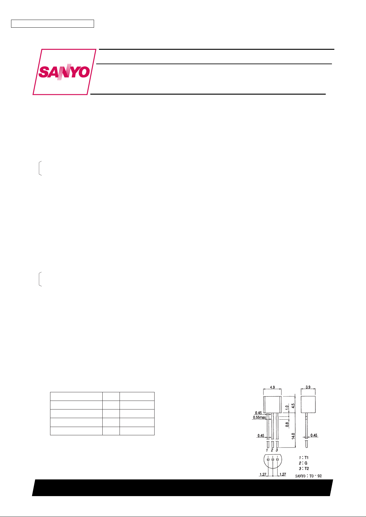
Trigger mode T2 T1 G
I + – +
II + – –
III – + +
IV – + –
Package Dimensions 1192B
(unit : mm)
DTA1
No.2283-2/3
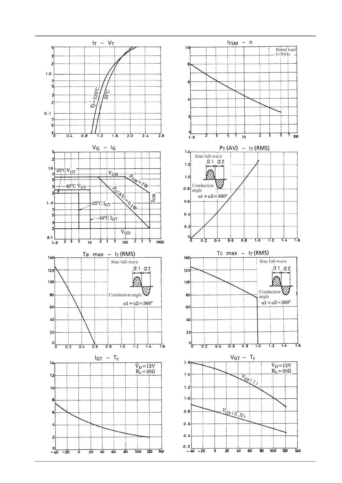
ON-State Voltage, VT– V
ON-State Current, I
T
– A
Gate Current, IG– V
Gate Voltage, V
G
– V
RMS ON-State Current, IT(RMS) – A
Average ON-State Power Dissipation, P
T
(AV) – W
RMS ON-State Current, IT(RMS) – A
Maximum Allowable
Case Temperature, Tc max – °C
Case Temperature, Tc – °C
Gate Trigger Voltage, V
GT
– V
Case Temperature, Tc – °C
Gate Trigger Current, I
GT
– mA
RMS ON-State Current, IT(RMS) – A
Maximum Allowable
Ambient Temperature, Ta max – °C
Number of Cycles at 50Hz, n
Surge ON-State Current, I
TSM
– A
 Loading...