

Page 1
e_dsr_m800.book Page 0 Friday, January 31, 2003 5:45 PM
Digital Video Recorder
Instruction manual
Manuel D'instructions
Manuel de Instrucciones
About this manual
Before installing and using this unit, please read
this manual carefully. Be sure to keep it handy for
later reference.
À propos de ce manuel
Avant d’installer et d’utiliser cet appareil, veuillez lire ce
manuel attentivement. Assurez-vous de le garder à
portée de la main pour référence ultérieure.
Acerca de este manual
Antes de instalar y usar este aparato, lea detenidamente
este manual. Asegúrese de guardarlo a mano para
futuras referencias.
English
GB
F
E
POWER
TIMER
FULL
LAN
(LINK/ACT.)
SEARCH
MENU RESET
MENU
REVIEW
ALARM
PLAY/
STOP
EXIT/OSD
CUE
STILL
REC/STOP
LOCK/REMOTE
USB
Page 2
e_dsr_m800.book Page 1 Friday, January 31, 2003 5:45 PM
PRECAUTION
CAUTION
RISK OF ELECTRIC SHOCK
DO NOT OPEN
CAUTION: TO REDUCE THE RISK OF ELECTRIC SHOCK, DO NOT
REMOVE COVER (OR BACK).
NO USER-SERVICEABLE PARTS INSIDE.
REFER SERVICING TO QUALIFIED SERVICE PERSONNEL.
WARNING: To reduce the risk of fire or electric shock, do
not expose this appliance to rain or moisture.
CAUTION: Changes or modifications not expressly
approved by the manufacturer may void the user’s authority
to operate this equipment.
The lightning flash with arrowhead symbol, within an
equilateral triangle, is intended to alert the user to the
presence of uninsulated “dangerous voltage” within the
product’s enclosure that may be of sufficient magnitude to
constitute a risk of electric shock to persons.
The exclamation point within an equilateral triangle is
intended to alert the user to the presence of important
operating and maintenance (servicing) instructions in the
literature accompanying the product.
This equipment has been tested and found to comply with
the limits for a Class B digital device, pursuant to part 15 of
the FCC Rules.
These limits are designed to provide reasonable protection
against harmful interference in a residential installation.
This equipment generated, uses and can radiate radio
frequency energy and, if not installed and used in
accordance with the instructions, may cause harmful
interference to radio communications. However, there is no
guarantee that interference will not occur in a particular
installation.
If this equipment does cause harmful interference radio or
television reception, which can be determined by turning
the equipment off and on, the user is encouraged to try to
correct the interference by one or more of the following
measures:
z Reorient or relocate the receiving antenna.
z Increase the separation between the equipment and
receiver.
z Connect the equipment into an outlet on a circuit
different from that to which the receiver is connected.
z Consult the dealer or an experienced radio/TV
technician for help.
For the customers in Canada
This class B digital apparatus complies with Canadian
ICES-003.
CAUTION
Danger of explosion if battery is incorrectly replaced.
Replace only with the same or equivalent type
recommended by the manufacturer.
Discard used batteries according to the manufacture’s
instructions.
Declaration of Conformity
Model Number : DSR-M800
Trade Name : SANYO
Responsible party : SANYO FISHER COMPANY
Address : 21605 Plummer Street,
Chatsworth, California 91311
Telephone No. : (818) 998-7322
z This device complies with Part 15 of the FCC Rules.
Operation is subject to the following two conditions:
(1) this device may not cause harmful
interference,and
(2) this device must accept any interference received,
including interference that may cause undesired
operation.
Location
For safe operation and satisfactory performance of your
unit, keep the following in mind when selecting a place for
its installation:
z Shield it from direct sunlight and keep it away from
sources of intense heat.
z Avoid dusty or humid places.
z Avoid places with insufficient ventilation for proper heat
dissipation. Do not block the ventilation holes at the top
and bottom of the unit. Do not place the unit on a carpet
because this will block the ventilation holes.
z Install the unit in a horizontal position only.
z Avoid locations subject to strong vibrations.
z Avoid moving the unit between cold and hot locations.
z Do not place the unit directly on top of a monitor TV, as
this may cause playback or recording problems.
Avoiding Electrical Shock and Fire
z Do not handle the power cord with wet hands.
z Do not pull on the power cord when disconnecting it
from an AC wall outlet. Grasp it by the plug.
z If any liquid is spilled on the unit, unplug the power cord
immediately and have the unit inspected at a factoryauthorised service centre.
z Do not place anything directly on top of this unit.
SERVICE
This unit is a precision instruments and if treated with care,
will provide years of satisfactory performance.
However, in the event of a problem, the owner is advised
not to attempt to make repairs or open the cabinet.
Servicing should always be referred to your dealer or
Sanyo Authorized Service Centre.
1
Page 3
00e_02_dsr_m800_6.fm Page 2 Thursday, February 6, 2003 10:08 AM
INTRODUCTION
Main features
This digital video recorder can be used to store images
recorded by a monitoring camera onto its built-in hard disk.
Comes with a large-capacity
(120 GB or 240 GB) hard disk.
For the 120 GB model, a hard disk upgrade is available
(sold separately) that gives you a total of 240 GB of
memory.
Complete range of recording/playback
functions
z You can play back and record images at the same
time.
z You can record and play back audio.
z The timer record function lets you make recordings
at different times each day. (JP.29)
The search function lets you instantly display
the desired image. (JP.18)
z Searching in order of alarm occurrence
z Searching by date/time
The security lock function lets you restrict
users, for data and equipment management.
(JP.34)
Expandable, can be connected to a PC
z The Ethernet terminal lets you connect the digital
video recorder to a network, for remote operation/
remote monitoring.*
z Network connection lets you control up to 1,000
DVRs (digital video recorders) using 4 PCs.*
z Can be connected to a system controller (sold
separately) using the RS-485 terminal.
z A CompactFlash reader can be connected using the
USB terminal, letting you upload/download menu
data.
Items marked by asterisks (*) require the VA-SW800
remote operation software (sold separately). For more
information, contact a Sanyo service center.
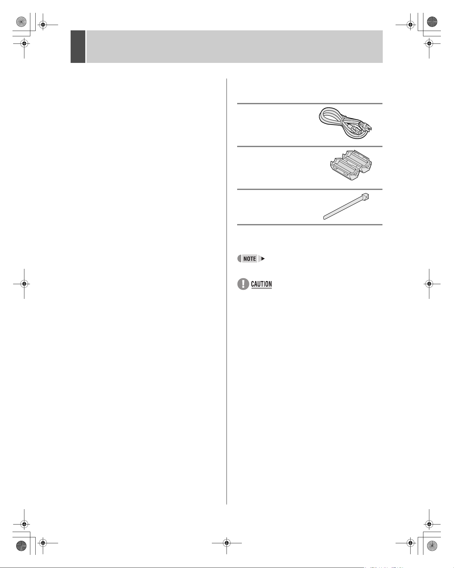
Accessories
Check that you have all the parts below.
Power cord
Ferrite core
(for LAN connection cable)
Power cord tie
Symbols used in this manual
Information describing operation methods
or how to get the most out of functions
Information describing the correct use of
the digital video recorder
(JP. xx) Indicates manual page to refer to.
Copyright
z This manual and software are copyrighted by Sanyo
Electric Co., Ltd.
z Brand and product names used in this manual are the
trademarks or registered trademarks of their respective
companies.
z Except for personal use, copyright law prohibits the use
of recorded copyrighted images without the permission
of the copyright holder
z Sanyo's DSR-M800 Digital Video Recorder uses
software components distributed as freeware based on
end user license agreements or copyright notifications
(collectively referred to as “EULAs”) set forth by third
parties.
2
Page 4

e_dsr_m800.book Page 3 Friday, January 31, 2003 5:45 PM
CONTENTS
INTRODUCTION
1 BEFORE USE..................................................5
Notes on handling internal hard disk drive
components .....................................................5
Do not use the digital video recorder in the
following locations:...........................................5
The hard disk and cooling fan are
consumables....................................................5
Installation conditions.......................................5
For important recordings..................................5
Hard disk protection .........................................6
Care .................................................................6
During extended disuse ...................................6
Backup battery .................................................6
OPERATION
1 SCREEN DISPLAY AND POSITION ............11
Operation display area...................................11
Changing the position of the operating
display............................................................11
2 SETTING THE LANGUAGE/CLOCK ............12
2 NAMES AND FUNCTIONS OF PARTS ......... 7
Front panel...................................................... 7
Rear panel....................................................... 8
3 INSTALLATION AND CONNECTIONS ......... 9
Basic connections ........................................... 9
System controller connections ........................ 9
Connecting a remote control circuit................. 9
Connecting cables to the control and alarm
terminals........................................................ 10
Connecting to a network ............................... 10
Connecting the power cord ........................... 10
5 NORMAL RECORDING/TIMER RECORDING
PLAYBACK .................................................. 16
Playback........................................................ 16
Playback while fast-forwarding/rewinding ..... 16
Viewing still images....................................... 17
Frame advance (reverse).............................. 17
To change the language ................................12
Setting the time ..............................................13
3 NORMAL RECORDING/TIMER
RECORDING .................................................14
Normal recording ...........................................14
Timer recording..............................................14
4 ALARM RECORDING ...................................15
Alarm recording..............................................15
6 SEARCHING FOR RECORDED IMAGES ... 18
Alarm search................................................. 18
Date/time search ........................................... 19
7 PREVENTING ACCIDENTAL OPERATION
(KEY LOCK FUNCTION).............................. 21
Setting the key lock function ......................... 21
Releasing the key lock function..................... 21
3
Page 5
e_dsr_m800.book Page 4 Friday, January 31, 2003 5:45 PM
CONTENTS
SETTINGS
MENU CONFIGURATION AND
OPERATIONS ...............................................22
Displaying the menu screen and sub-menu
screens ..........................................................22
To restore menu setting items to their
initial values ...................................................22
Overview of sub-menus .................................23
1 LANGUAGE/CLOCK SET.............................24
<DAYLIGHT SAVING> settings.....................24
<EXT.CLOCK SET> settings .........................25
2 REC MODE SET............................................27
<REC MODE SET> setting items ..................27
Settings ..........................................................28
Starting recording again when the FULL
indicator lights ................................................28
3 TIMER REC SET ...........................................29
Timer setting items.........................................29
Timer reservations every day at the same time
with the same image quality...........................29
To cancel all timer reservations .....................30
Timer reservations spanning more than
24 hours .........................................................30
Setting holidays..............................................31
INTRODUCTION OPERATION SETTINGS OTHER OTHER OTHER OTHER
4 DISPLAY/BUZZER SET ............................... 32
<DISPLAY/BUZZER SET> setting items ...... 32
Settings ......................................................... 33
5 SECURITY LOCK SET................................. 34
Password setting example ............................ 34
Password setting........................................... 34
Setting passwords......................................... 34
Setting the user password............................. 35
Setting the authorization for recording and
playback operations ...................................... 36
Setting the security lock ................................ 36
6 RS-485/NETWORK SET .............................. 37
Network connections and settings ................ 37
RS-485 connections and settings ................. 38
7 POWER FAILURE/USED TIME ................... 39
8 MENU UPLOAD/DOWNLOAD ..................... 40
Settings ......................................................... 40
9 INITIALIZE/ADD HDD .................................. 42
Initializing the hard disk................................. 42
Adding a hard disk (120 GB model only) ...... 43
OTHER
1 INTERFACE SPECIFICATIONS ...................44
RS-485 specifications ....................................44
RS-485 termination switch settings................44
DVR/VCR command table .............................45
2 SPECIFICATIONS ........................................ 46
Dimensions ................................................... 47
4
Page 6

e_dsr_m800.book Page 5 Friday, January 31, 2003 5:45 PM
1 BEFORE USE
Notes on handling internal hard disk
drive components
This unit has a built-in hard disk drive (HDD).
Be sure to observe the following points carefully when
operating, setting-up and servicing the unit.
Do not subject the unit to shocks or vibration.
If the unit is subjected to shocks or vibration, it may damage
the HDD or cause corruption of the data stored in the HDD.
z Do not move the unit while the power is turned on.
Always be sure to turn off the power before removing
the unit from or placing it onto the rack.
z When transporting the unit, pack it securely using the
specified packing materials. In addition, use a method
of transportation that minimizes vibration.
z When placing the unit down on a surface such as a
floor, attach the specified feet to the base of the unit
and place it down gently. If the feet are not attached,
place the unit down very carefully so that it does not
make any noise.
Do not move the unit for 30 seconds after
turning off the power.
After the power is turned off, the disk inside the HDD will
continue to spin for a brief period due to inertia, and the
heads will be in an unstable state.
During this time, the unit is even more susceptible to
shocks and vibration than when power is being supplied.
Make sure that the unit is not subjected to even gentle
vibration for at least 30 seconds after turning off the power.
Do not operate the unit when condensation has
formed.
If the unit is operated when condensation has formed, it
may cause operating problems.
If sudden changes in the ambient temperature occur, wait
for the temperature to stablize before operating the unit.
Notes when replacing the HDD
Be sure to follow the correct replacement procedure when
replacing the HDD.
z HDDs that have been removed from their packing may
not operate correctly if they are subjected to any shocks
and vibration. It is recommended that you place HDD
onto a soft, level surface with the printed circuit board
facing upward after unpacking it.
z Be careful not to subject the HDD to shocks or vibration
when removing and tightening screws as part of the
HDD replacement procedure. Make sure that all screws
are tightened securely so that they will not become
loose.
The HDD is sensitive to static electricity, so you should
take proper precautions to prevent static electricity
buildup.
Handling the HDD unit by itself
If transporting or storing the HDD unit by itself, always be
sure to pack it in the specified packing first.
In addition, use a method of transportation that minimizes
the vibration.
If the HDD becomes damaged, handle the unit and the
damaged HDD that has been removed in order for it to be
replaced carefully to prevent the problem from being
aggravated until as the nature of the problem can be
checked and analyzed.
Do not use the digital video recorder in
the following locations:
z The hard disk is sensitive to dust, vibrations and
shocks, and should also not be used near magnetic
objects. To prevent loss of recorded data, observe the
following precautions:
z Do not subject the digital video recorder to shocks.
z Do not use the digital video recorder on a vibrating or
unstable surface.
z Do not disconnect the power plug from the wall outlet
during recording or playback.
z Do not use the digital video recorder in areas of
extreme temperature changes (10ºC or more per hour).
z Condensation may occur if the digital video recorder is
moved to an area of extremely different temperature or
high humidity. If the digital video recorder is used with
condensation inside it, operating problems may occur.
z Do not install the digital video recorder in areas of
constant vibration such as motor vehicles or trains.
The hard disk and cooling fan are
consumables.
Under use in an ambient temperature of 25ºC, the hard disk
should generally be replaced after 2 years, and the cooling
fan after 3 years. These figures are intended as guidelines
only, and are not guarantees of part performance.
The POWER indicator flashes if a problem occurs in the
hard disk or fan. (JP.10)
Installation conditions
The digital video recorder has ventilation holes on its left,
rear and bottom panels. Make sure these holes are not
blocked after installation.
Do not use the unit in an area of poor ventilation such as a
bookshelf or box.
When installing the unit in a rack, ensure a gap of at least 5
cm at the top and bottom.
For important recordings
z Always make a test recording beforehand to check that
the digital video recorder's playback is normal.
z Note that no compensation will be provided for losses
due to recording or playback problems arising from
problems with the digital video recorder or its connected
devices during operation.
5
Page 7
e_dsr_m800.book Page 6 Friday, January 31, 2003 5:45 PM
1 BEFORE USE
z To be prepared for malfunctions or accidents, back up
important recordings periodically, or record using
mirroring.
Hard disk protection
The hard disk is checked automatically at power ON. If a
hard disk problem is found, the POWER indicator flashes.
If you need to initialize the disk or save images stored on
the disk, contact a Sanyo service center.
Care
z To clean the digital video recorder, unplug the power
plug from the wall outlet and wipe the unit lightly with a
soft cloth.
z To remove heavy grime, wipe the digital video recorder
with a well-wrung cloth soaked in a solution of water
and neutral detergent, and then wipe it with a dry cloth.
z Do not clean the unit with benzene or paint thinner.
Doing so may break down the finish or strip the paint.
z When using a chemical cloth, be sure to follow the
precautions provided with it.
z Do not spray insecticide or other volatile chemicals on
the cabinet. Do not allow rubber or vinyl products to
come into contact with the digital video recorder for
extended periods.
Doing so may break down the finish or strip the paint.
INTRODUCTION SETTINGS OTHER OTHER OTHER OTHER
During extended disuse
Extended disuse may cause problems in functions, so turn
the power on and operate the unit occasionally during such
periods.
Backup battery
The digital video recorder comes with a built-in lithium
battery. When the digital video recorder has been
connected to a wall outlet for at least 48 hours and the date
and time have been set, the clock function will continue to
operate for up to 30 days after the power plug is
disconnected.
When disposing of the digital video recorder, contact a
Sanyo service center for information on how to dispose of
the lithium battery.
6
Page 8
132 5 6 7 8 9 11 12
4 10
e_dsr_m800.book Page 7 Friday, January 31, 2003 5:45 PM
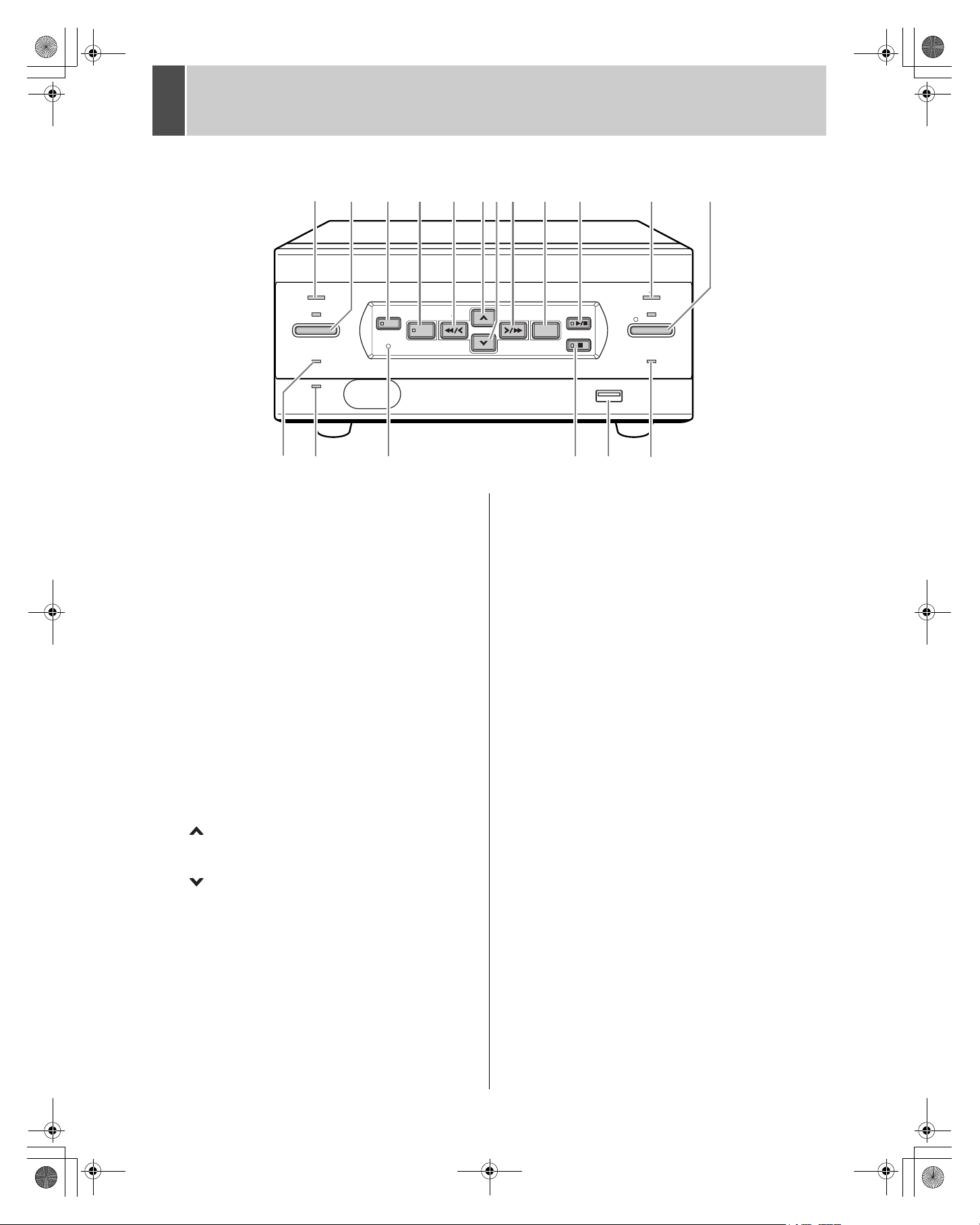
2 NAMES AND FUNCTIONS OF PARTS
Front panel
POWER
TIMER
FULL
LAN
(LINK/ACT.)
SEARCH
MENU RESET
MENU
REVIEW
EXIT/OSD
CUE
13 14 15 1716 18
1. POWER indicator
10. [PLAY/STOP] button
Lights when the power is ON.
Flashes when there is a problem with the hard disk or
fan. (JP.10)
11. ALARM indicator
2. [TIMER] button and indicator (JP.14)
When the button is pressed while recording or stopped,
the digital video recorder enters timer record standby,
12. [REC/STOP] button and indicator
and the indicator lights. When the set time arrives, the
digital video recorder starts timer recording.
3. [SEARCH] button and indicator (JP.18)
When the button is pressed while recording or stopped,
the indicator lights, and the search setting screen
13. FULL indicator (JP.14)
appears.
4. [MENU] button
Used to display the menu screens (setting screens).
The indicator lights when a menu screen is displayed.
14. LAN indicator
5. [REVIEW] button
When pressed during playback, lets you rewind the
image while watching it on screen. Also used for menu
15. [MENU RESET] button (JP.22)
screen operations.
6. [ ] button
Used to move the cursor in menu screens up. Also used
16. [STILL] button
to change setting values.
7. [ ] button
Used to move the cursor in menu screens down. Also
used to change setting values.
8. [CUE] button
When pressed during playback, lets you fast-forward
17. USB terminal (JP.40)
18. LOCK/REMOTE indicator (JP.21, P.34)
the image while watching it on screen. Also used for
menu screen operations.
9. [EXIT/OSD] button
Returns to the normal screen when the main menu or a
sub-menu is displayed.
ALARM
PLAY/
STOP
STILL
REC/STOP
LOCK/REMOTE
USB
Plays back the normal image (indicator lights). When
pressed during playback, stops playback.
Flashes when recording an alarm image.
Starts normal recording. Indicator lights during
recording.
During recording, pressing the button for at least 3
seconds stops recording and turns off the indicator.
Lights when the remaining memory in the hard disk’s
recording area has reached zero and recording has
stopped.
Lights when the digital video recorder is connected to a
network. Flashes when data is being sent and received.
Used to initialize the currently displayed menu settings,
and to set the time.
When pressed during playback, freezes the screen
image (the indicator lights). Pressing the button again
resumes playback.
Used to connect a CompactFlash memory card reader.
Lights when operations have been locked by the key
lock or security lock setting.
If an operation button is pressed when the security lock
is set, a buzzer sounds. The key lock cannot be set
during playback.
The indicator flashes at 1Hz when there is a network
connection, and flashes at 4Hz when there is a network
connection while locked.
7
Page 9
1325678
4
e_dsr_m800.book Page 8 Friday, January 31, 2003 5:45 PM
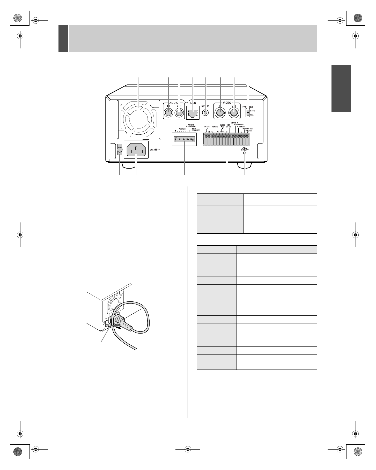
2 NAMES AND FUNCTIONS OF PARTS
Rear panel
910 11 12
1. FAN
2. AUDIO IN terminal
3. AUDIO OUT terminal
4. LAN terminal (JP.37)
5. MIC IN terminal
6. VIDEO IN terminal
7. VIDEO OUT terminal
8. TV SYSTEM selector switch
Used to select the video signal between NTSC and PAL
systems for the camera input and TV monitor output
connected to the digital video recorder.
9. Power cord holder
Secure the power cord to the holder using the cord tie
(accessory) as shown in the illustration.
Cord tie
10. AC INLET
AC power input terminal (3-core)
13
11. Dip switches (JP.37)
ADDRESS
ADDRESS AUTO
MANUAL
RS485 TERMINATE RS-485 termination ON/OFF switch
Used to set the device address of the
TCP/IP or RS-485 (SSP) interface.
Used to select whether to acquire the
IP address by automatic allocation, or
to specify the lowest-order byte of the
address using the dip switches.
12. Control and alarm terminals
Pin Signal
RS485A To RS-485 terminal signal A *
RS485B To RS-485 terminal signal B *
C Common *
REMOTE For wired remote control (VA-RMN01)
C Common
CLOCK ADJ IN Input for clock setting
CLOCK ADJ OUT Output for clock setting
C Common
NON REC OUT NON-REC output
ALARM IN Alarm input
ALARM RESET Alarm reset input
ALARM OUT Alarm output
C Common
WARNING OUT Warning output *
FULL OUT Recording area full warning
1
2
1
1
INTRODUCTION SETTINGS OTHER OTHER OTHER OTHER
*1Used for twisted-pair cable connection.
2
*
The following warnings are output:
z Hard disk drive error z Fan error z Recording error
z No input signal when VIDEO LOSS is ON.
13. ALL RESET switch
Resets the clock and backup mode setting.
8
Page 10
e_dsr_m800.book Page 9 Monday, March 10, 2003 2:21 PM
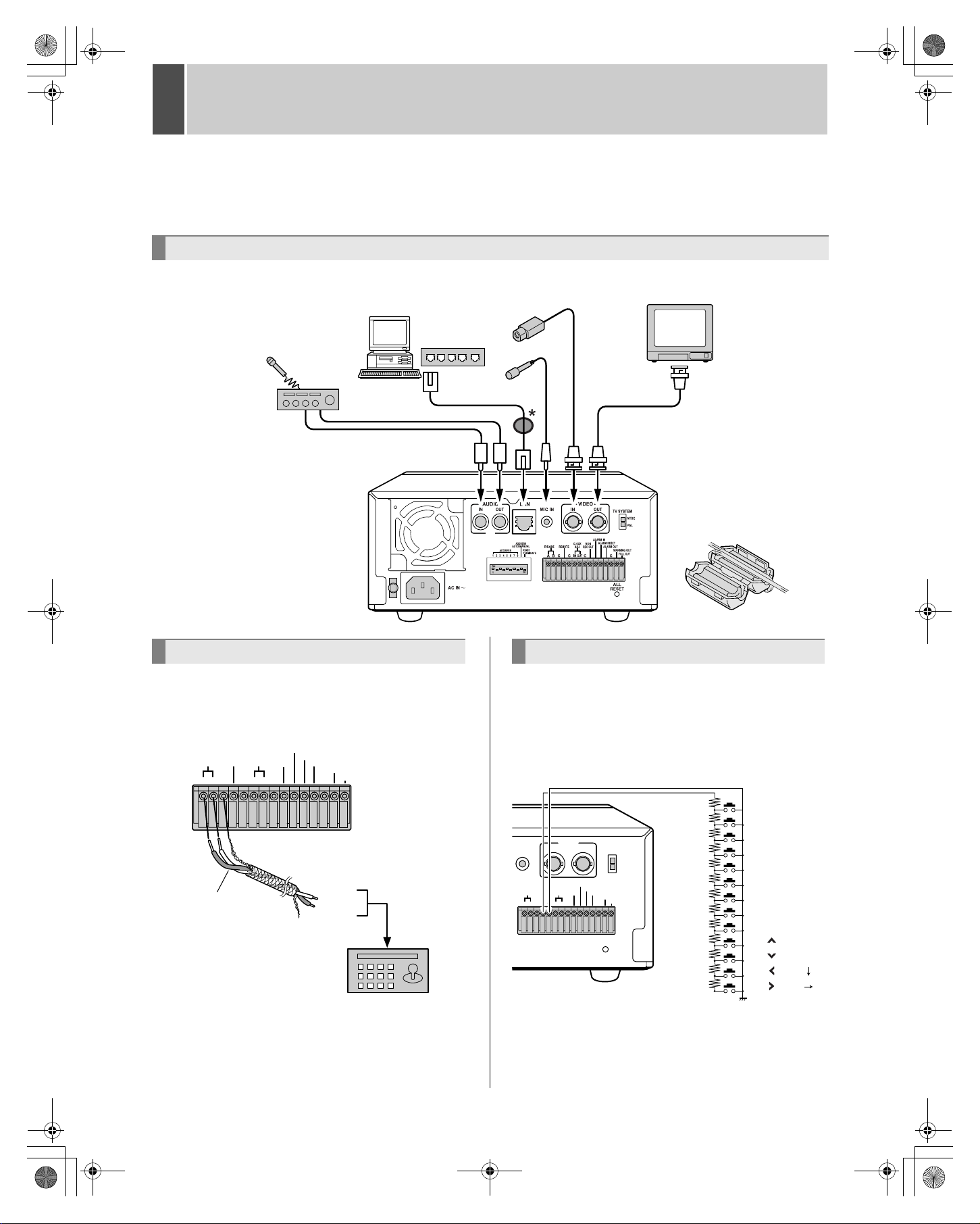
3 INSTALLATION AND CONNECTIONS
This section describes how to connect the digital video recorder to the CCTV camera and other devices. Be sure to read the
instruction manuals for each connected device. Make connections carefully. Improper connections can cause smoke or
malfunctions.
Basic connections
The connections for the camera, TV monitor, microphone and PC are shown below.
PC
or
hub
CCTV camera (sold separately)
TV monitor
(sold separately)
Amp
System controller connections
The connections for a system controller are shown below.
Use a twisted-pair cable (sold separately) to connect rear
panel control terminals A, B and C (ground). Connect
signal A to signal A, and signal B to signal B.
ALARM IN
OUT
NON
REC OUT
ALARM RESET
ALARM OUT
To signal B
To signal A
WARNING OUT
FULL OUT
RS-485
terminal
System controller
(sold separately)
RS485
ABC C C C
ADJ
IN
CLOCK
REMOTE
Twisted-pair cable
Ground
z Twisted-pair cable
Can reduce interference on the signal caused by noise
generated by other cables.
Microphone
Video input
terminal
Use a shielded LAN
*
connection cable, and
wind it once around the
supplied ferrite core.
Connecting a remote control circuit
The connections for a remote control circuit are shown
below. Making the connections shown below lets you
operate the digital video recorder by remote control.
z Create the remote control circuit shown in the
illustration, and connect it to the remote control input
terminals (among the control terminals).
RO 1.2K
R1 0.3K
VIDEO
IN
CLOCK
IN
OUT
TV SYSTEM
NTSC
PAL
ALARM IN
ALARM RESET
NON
ALARM OUT
ADJ
REC OUT
WARNING OUT
ALL
RESET
FULL OUT
OUT
MIC IN
REMOTE
RS485
ABC C C C
( ): When VA-RMN01 is used
Use a resistance of 1/10 ohms or more and with a D ranking
(precision 0.5% or finer).
R2 0.43K
R3 0.51K
R4 0.62K
R5 0.75K
R6 0.91K
R7 1.1K
R8 1.3K
R9 2.0K
R10 2.4K
R11 3.6K
R12 5.6K
SW1:STOP
SW2:PAUSE/EXIT
SW3:REW
SW4:FF
SW5:PLAY
SW6:REC
SW7:MENU
SW8:SEARCH (REVERSE)
SW9:
SW10:
SW11:
(SHIFT )
SW12:
(SHIFT )
9
Page 11
e_dsr_m800.book Page 10 Friday, January 31, 2003 5:45 PM
3 INSTALLATION AND CONNECTIONS
z Connect the cable of the wired remote control (VA-
RMN01) (sold separately) to the remote control input
terminals (among the control terminals).
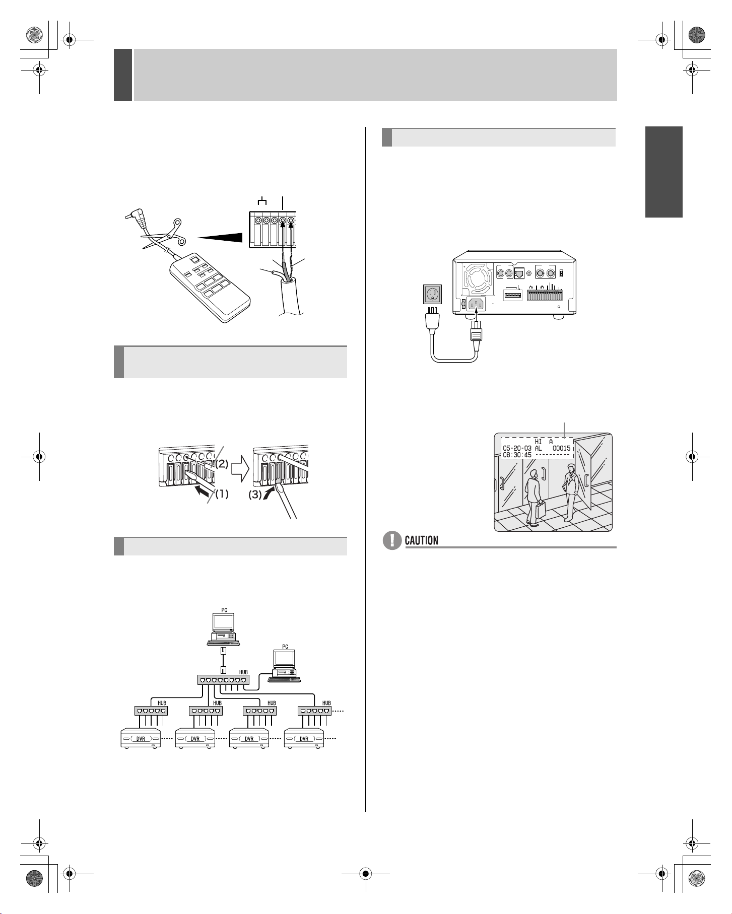
Cut the plug off the cord, and connect the red wire to
“REMOTE” and the bare wire to “C”.
REMOTE
RS485
ABC C
Red wire
Bare wire
White
wire
VA-RMN01
Connecting cables to the control and
alarm terminals
(1) Push in the lock pin with a flat-blade screwdriver.
(2) Insert the cable.
(3) Pull out the lock pin with a flat-blade screwdriver. The
cable is now fixed in place.
Cable
Connecting the power cord
1 When you have finished making all the
other connections, insert the power
plug into the wall outlet.
There is no power switch. All the display indicators flash for
approximately 30 seconds, then the POWER indicator
lights. The monitor screen displays the camera image.
AUTO/MANUAL
LAN
ADDRESS
RS485
TERMINATE
VIDEO
IN
MIC IN
CLOCK
REMOTE
RS485
ADJ
IN
OUT
ABC C C C
OUT
TV SYSTEM
NTSC
PAL
ALARM IN
ALARM RESET
NON
ALARM OUT
REC OUT
WARNING OUT
FULL OUT
ALL
RESET
AUDIO
IN
OUT
ADDRESS
12345678
AC IN
Power cable
z When turning the power ON for the first time
"PLEASE SET THE CLOCK" is displayed on the monitor
screen. Follow the steps on page 12 to set the clock.
z If the clock is already
Operating display
set
The operation display
area is displayed.
INTRODUCTION SETTINGS OTHER OTHER OTHER OTHER
Flat-blade screwdriver
Connecting to a network
The VA-SW800 application software (sold separately) lets
you control the digital video recorder, and monitor live
images, recorded images and audio through a network.
z If the POWER indicator flashes
The digital video recorder has a self-check function that
indicates problems. If there is a problem at power ON or
during operation, the type of problem is indicated by how
rapidly the POWER indicator flashes. Contact a Sanyo
Authorized Service Center if the POWER indicator flashes.
4 flashes per second:
The disk is checked automatically at power ON. If a hard
disk problem is found, the POWER indicator flashes,
and the hard disk must be replaced or reformatted. If you
need to save images stored on the disk, contact a Sanyo
Authorized Service Center.
1 flash per second:
Fan problem
z If you disconnect the power cable
Don’t move the digital video recorder for 30 seconds
after power OFF.
The disk in the hard disk drive briefly keeps spinning
after power OFF due to inertia, during which time the
head is unstable. At this time, the disk is sensitive to
shocks or vibrations, so avoid even light shocks.
10
Page 12
e_dsr_m800.book Page 11 Friday, January 31, 2003 5:45 PM
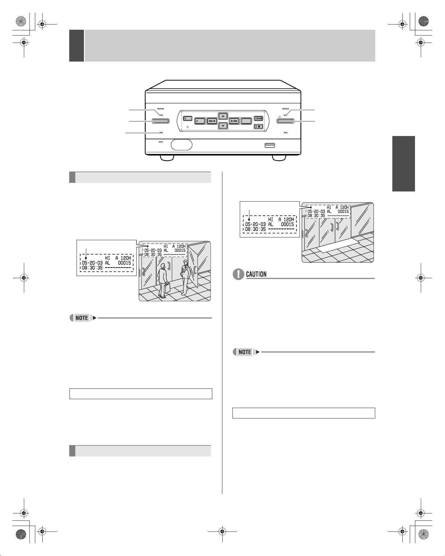
1 SCREEN DISPLAY AND POSITION
At power ON, the operation display area appears at the top
left of the monitor screen.The operation display area shows
the date/time, image quality, remaining time, and other
information needed for operations.
Operation display area
Example: Normal screen
(1) (2)
(5)
(6)
Playback screen
(1)
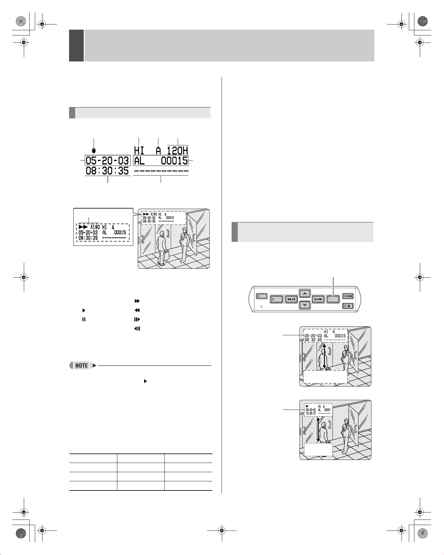
(1) Operating symbol display
Displays the operation (such as recording or playback)
and playback speed.
z : Recording : Fast-forward playback
: Playback : Rewind playback
: Still : Slow playback
: Reverse slow playback
The playback speed is displayed during fast-forward or
fast-rewind playback at 15 times the normal playback
speed or faster, and during slow or reverse slow playback.
(4)(3)
(7)
(8)
(5) Date display (JP.13)
Shows the month/day/year.
05-20-03 (month-day-year)
(6) Time display (JP.13)
“00:00:00” is displayed when you turn the power ON for
the first time. The digital video recorder uses the date and
time to manage recording and playback points.
(7) Alarm display and alarm count display (JP.15)
When you set an alarm using the “Alarm recording” menu
item, the alarm display area appears as shown below.
z Alarm display
When alarm recording is set, “Alarm” appears.
During alarm recording, the “Alarm” display flashes.
z Alarm count display
Displays the total number of alarms that have been
generated.
(8) Name set for the digital video recorder
Displays the name set for the digital video recorder
when it is controlled by a network.
Changing the position of the
operating display
Press the [EXIT/OSD] button repeatedly.
Pressing the [EXIT/OSD] button repeatedly lets you move
or erase the operation display area.
[EXIT/OSD] button
SEARCH
MENU RESET
Normal screen
Operation
display area
MENU
REVIEW
CUE
EXIT/OSD
PLAY/
STOP
STILL
z During simultaneous recording and playback, the
display indicates playback ( ).
(2) Image quality display (JP.27)
Displays the quality of the image that can be recorded
on the hard disk. Set to “HIGH” in the initial settings.
(3) Audio recording
Displays “A” when audio recording has been set.
(4) Remaining time display
Unless “OVER WRITE” is set for recording, displays the
remaining amount of recording time, as shown below.
Remaining time
1 hour or more 1 hour increments 1H
Less than 1 hour
Less than 10 minutes 1 minute increments
Displayed increment
10 minute increments
11
Playback screen
Operation
display area
Example
10M
1M
Page 13
e_dsr_m800.book Page 12 Friday, January 31, 2003 5:45 PM
2 SETTING THE LANGUAGE/CLOCK
[MENU] button
POWER
SEARCH
TIMER
FULL
LAN
(LINK/ACT.)
MENU
MENU RESET
This section describes how to set the language displayed
on the monitor and how to set the digital video recorder’s
internal clock.
[Settings] ( indicates initial setting.)
Item Setting Description
ENGLISH
(1) LANGUAGE
(2) CLOCK SET Sets the date and time.
FRANCAIS Sets the language to French.
ESPAÑOL
Sets the language to
English.
Sets the language to Spanish.
[] button [ ] button
PLAY/
STOP
REVIEW
EXIT/OSD
CUE
STILL
[ ] button
To change the language
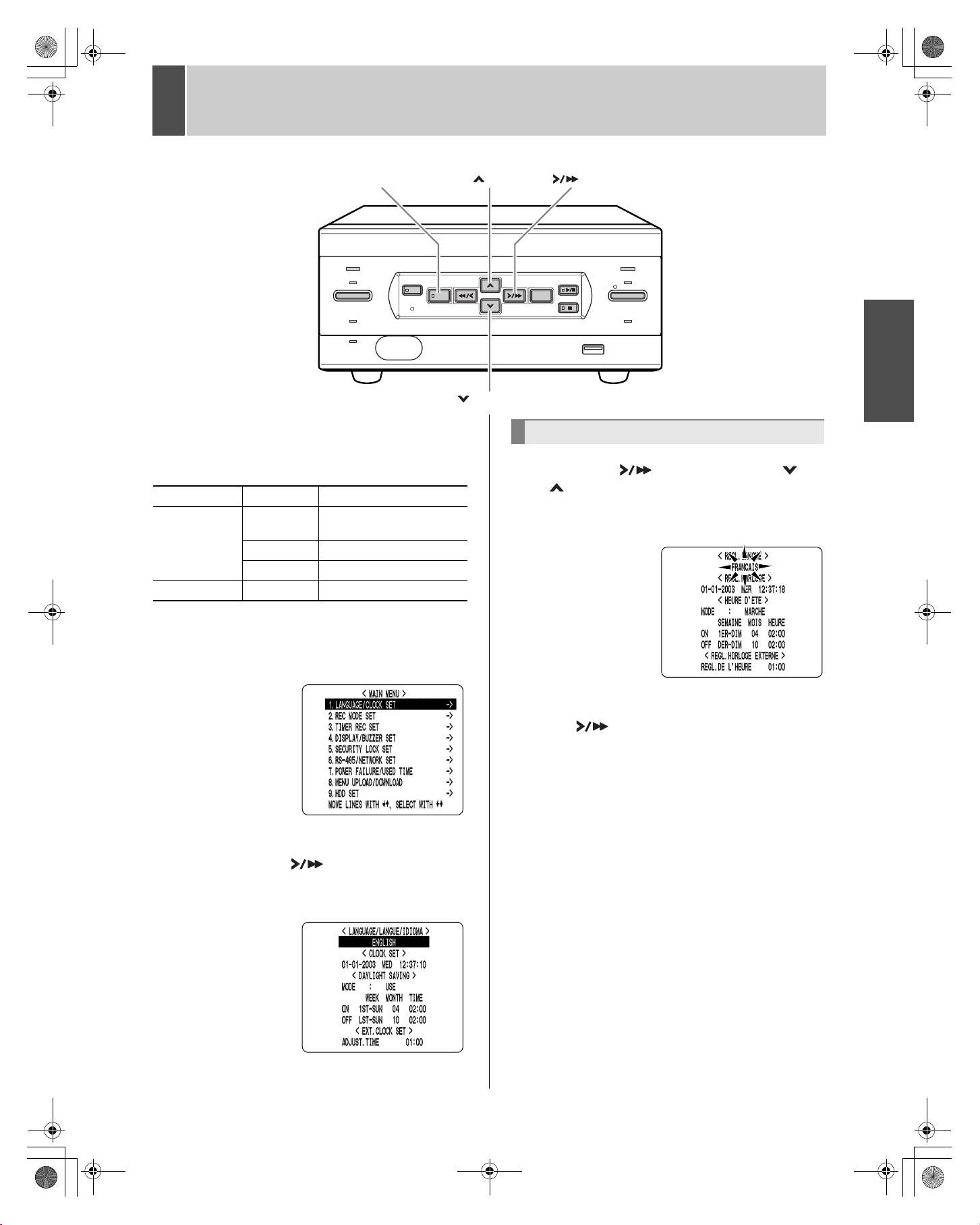
3 Press the [ ] button, then the [ ] or
[ ] button to select the desired
language.
The set item flashes.
INTRODUCTION OPERATION SETTINGS OTHER OTHER OTHER OTHER
ALARM
REC/STOP
LOCK/REMOTE
USB
1 Press the [MENU] button.
The [MENU] button lights, and the <MAIN MENU> screen
appears.
2 Select, “1. LANGUAGE/CLOCK SET”,
and press the [ ] button.
The <LANGUAGE/LANGUE/IDIOMA> screen
appears.The cursor is positioned on ENGLISH.
4 When you have made a selection, press
the [ ] button.
The cursor moves to the date and time.
The language has now been set.
To return to the normal screen, press the [EXIT/OSD]
button.
12
Page 14
e_dsr_m800.book Page 13 Friday, January 31, 2003 5:45 PM
213SETTING THE LANGUAGE/CLOCK
Setting the time
(Initial setting: 01-01-2003 WED 00:00:00)
Be sure to set the correct date and time. The digital video
recorder stores the times of recordings for use in operations
such as playback and search/playback.
Example: Setting May 20, 2003, 8:30 AM
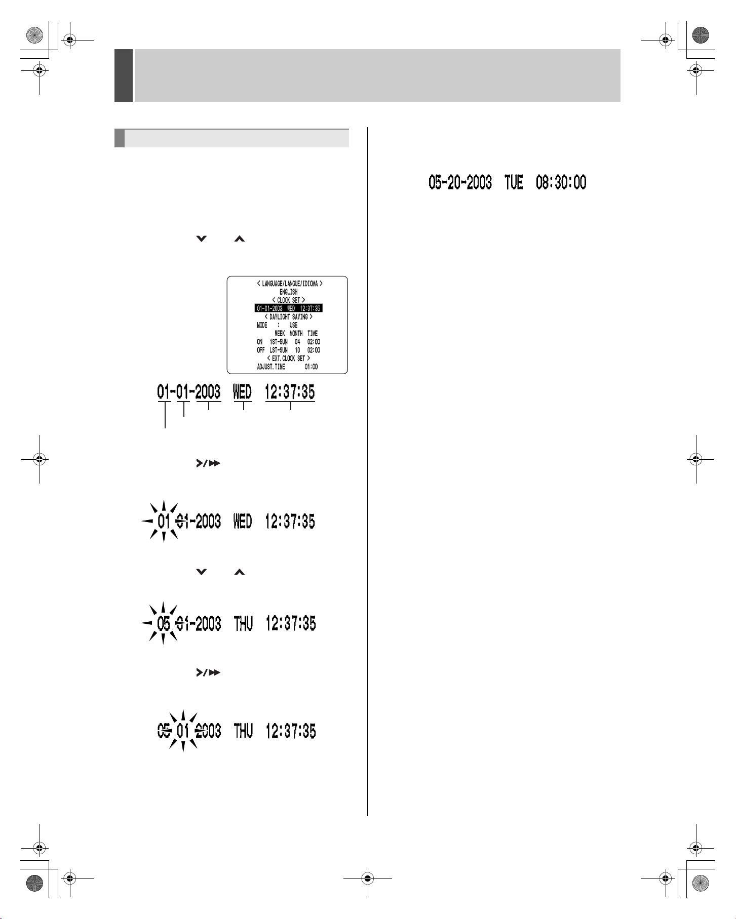
3 Press the [ ] or [ ] button to move
the cursor to the date and time under
<CLOCK SET>.
MONTH
DAY
YEAR
WEEK TIME
7 Use the same procedure to set the day
(20 in this example), year (2003), hour
(08) and minute (30)
When you have set the minute, the cursor moves to
“MODE” under <DAYLIGHT SAVING>, and the clock starts
from 00 seconds.
z “WEEK” is set automatically.
z The time is stopped during clock setting.
8 Press the [EXIT/OSD] button.
The display returns to the normal screen.
4 Press the [ ] button.
“01” (indicating the month) flashes.
5 Press the [ ] or [ ] button to select
“05”.
6 Press the [ ] button.
“01” (indicating the day) flashes.
Page 15
e_dsr_m800.book Page 14 Friday, January 31, 2003 5:45 PM
3 NORMAL RECORDING/TIMER RECORDING
INTRODUCTION OPERATION SETTINGS OTHER OTHER OTHER OTHER
TIMER indicator
[TIMER] button
FULL indicator
POWER
TIMER
FULL
LAN
(LINK/ACT.)
SEARCH
MENU RESET
MENU
Normal recording
Follow the steps below to record the monitored image onto
the hard disk.
1 Press the [REC/STOP] button.
The REC indicator lights.“z” (the recording symbol)
appears on the screen, and recording starts.
Recording symbol
REVIEW
ALARM
PLAY/
STOP
EXIT/OSD
CUE
STILL
REC/STOP
LOCK/REMOTE
USB
REC indicator
[REC/STOP] button
1 Press the [TIMER] button.
The TIMER indicator lights, and the digital video recorder
enters timer recording standby mode.
Recording symbol
z When you record for the first time, the initial settings are
used. To change the image quality, see P.27.
z When the remaining space for recording reaches zero,
recording ends and the FULL indicator lights. You can
start recording from the beginning again by changing
the “OVER WRITE” recording setting. (JP.27)
z You can record and play back images at the same time.
See P.16 for the procedure.
Ending normal recording
2 Press the [REC/STOP] button for about
3 seconds.
The REC indicator goes out and recording stops.
Timer recording
z A warning tone sounds if timer recording hasn’t been
set.
(1) See P.29 for how to set timer recording.
(2) When the time specified in the timer settings arrives,
the REC indicator lights, “z” (the recording symbol)
appears in the screen, and recording starts.
(3) When the set end time arrives, the REC indicator goes
out, and recording stops.
z When the remaining memory space for recording
reaches zero, recording ends, and the FULL indicator
lights. You can start recording from the beginning again
by changing the “OVER WRITE” setting. (JP.27)
z You can record and play back images at the same time.
See P.16 for the procedure.
Stopping during timer recording
2 Press the [TIMER] button.
The [TIMER] indicator goes out and recording ends.
Follow the steps on the right to record the monitored image
onto the hard disk at the set time.
14
Page 16

e_dsr_m800.book Page 15 Friday, January 31, 2003 5:45 PM
4 ALARM RECORDING
POWER
SEARCH
TIMER
FULL
LAN
(LINK/ACT.)
MENU
MENU RESET
Alarm recording
Follow the steps below to have the digital video recorder
record an alarm image only when alarm input is detected
during recording.
z Check that the cable of the device required for alarms is
connected to the ALARM terminal. (JP.8)
1 Set alarm recording.
The default settings are shown below. See P.27 for how to
change these settings.
z ALARM MODE: “ENABLED”
Alarm recording is always performed, whether or not
timer recording is set.
z ALARM DURATION: “20SEC”
Recording is performed for 20 seconds for each alarm
signal received.
REVIEW
ALARM
PLAY/
STOP
EXIT/OSD
CUE
STILL
REC/STOP
LOCK/REMOTE
USB
ALARM indicator
3 Ending alarm recording
When the alarm duration time (default setting: 20 seconds)
ends, “AL” disappears from the operating display, the
ALARM indicator stops flashing, and recording ends.
z When the hard disk’s remaining space for recording
reaches zero, the FULL indicator lights and recording
ends. You can start recording from the beginning again
by changing the recording setting. (JP.27)
2 When alarm input is detected.
Counts number of
alarms.
z When an alarm is received, “AL” flashes in the
operation display area, the ALARM indicator flashes,
and the alarm image is recorded.
z Each time an alarm is received, the alarm count in the
operation display area is incremented by 1.
15
Page 17

e_dsr_m800.book Page 16 Friday, January 31, 2003 5:45 PM
5
NORMAL RECORDING/TIMER RECORDING PLAYBACK
Follow the steps below to play back images recorded on the
hard disk.
Playback
[ ] button
SEARCH
MENU RESET
MENU
REVIEW
CUE
EXIT/OSD
PLAY/
STOP
STILL
1 Press the [ ] button.
The [ ] button lights, and “ ” appears in the operation
display area. The images stored in the normal recording
area are played back.
Playback while fast-forwarding/rewinding
[ ] button
SEARCH
MENU
MENU RESET
Press the [ ] or [ ] button during playback or when
a still image is displayed.
When you press the [ ] button, appears in the
operating display, and the playback fast-forwards at 7.5
times the normal playback speed.
When you press the [ ] button, appears in the
operating display, and the playback fast-rewinds at 7.5
times the normal playback speed.
[ ] button [ ] button
REVIEW
EXIT/OSD
CUE
[ ] button [ ] button
PLAY/
STOP
STILL
INTRODUCTION OPERATION SETTINGS OTHER OTHER OTHER OTHER
z Image playback starts from the point at which recording
started.
z If “OVER WRITE” has been set in the normal recording
settings, playback starts with the oldest recorded image
when the recording is played back for the first time.
z When playback ends, the digital video recorder pauses
automatically.
The stop display ( ) appears in the operation display
area, and the [ ] button lights.
z After playback is stopped, it will resume from the
stopped point the next time it is started.
Ending playback
2 Press the [ ] button.
Playback ends.
Playing back an image near the point of
recording
The digital video recorder prioritizes recording operations,
so the playback image may freeze temporarily.
To change the fast-forward speed
Press the [ ] button while fast-forwarding.
Press the button once to increase the speed to 15 times the playback speed,
twice to increase the speed to 30 times the playback speed, and 3 times to
increase the speed to 180 times the playback speed.
To change the rewind speed
Press the [ ] button while rewinding.
Press the button once to increase the speed to 15 times the playback speed,
twice to increase the speed to 30 times the playback speed, and 3 times to
increase the speed to 180 times the playback speed.
Ending fast-forward/rewind
Press the [ ] button.
Normal playback starts.
Fast-forward
Reverse
-15X
-30X
-180X
-7.5X
()
Playback
(still image)
()
15X
7.5X
direction
180X
30X
16
Page 18

e_dsr_m800.book Page 17 Friday, January 31, 2003 5:45 PM
517NORMAL RECORDING/TIMER RECORDING PLAYBACK
Viewing still images
SEARCH
MENU RESET
MENU
REVIEW
CUE
EXIT/OSD
PLAY/
STOP
STILL
[ ] button
1 During playback, press the [ ] button.
The image becomes a still image (freezes).
appears in the operation display area.
To resume playback
Frame advance (reverse)
[ ] button
SEARCH
MENU
REVIEW
MENU RESET
CUE
[ ] button [ ] button
With a still image displayed, press the []
button.
The still image advances by one frame.
Press the [ ] button while a still image is
displayed.
The still image moves back three frames.
Slow playback
Press the [ ] button for at least 2 seconds.
The playback speed slows to 1/8 the normal speed.
Pressing the [ ] button again switches the playback
speed to 1/4 the normal speed.
Pressing the button twice switches the playback speed to 1/
2 the normal speed.
EXIT/OSD
PLAY/
STOP
STILL
2 Press the [ ] button.
Slow reverse playback
Press the [ ] button for at least 2 seconds.
The playback speed slows to 1/8 the normal speed.
Pressing the [ ] button again switches the playback
speed to 1/4 the normal speed.
Pressing the button twice switches the playback speed to 1/
2 the normal speed.
Reverse
slow
Slow
direction
direction
1/2
1/4
Press for at
least 2 seconds
With still image
-1/8
display
1/8
Press for at
least 2 seconds
-1/4
-1/2
Page 19

e_dsr_m800.book Page 18 Friday, January 31, 2003 5:45 PM
6 SEARCHING FOR RECORDED IMAGES
Images recorded on the hard disk can be searched and
played back. There are two search methods available.
Image to search
Search in <Search> screen
(1)
(2)
z You can use the button operations to freeze, fast-
forward or perform other operations on retrieved
images being played back.
Alarm search
Lets you search and play back all the alarm images on the
hard disk.
[ ] button[SEARCH] button [ ] button
SEARCH
MENU RESET
MENU
REVIEW
CUE
[ ] button
EXIT/OSD
PLAY/
STOP
STILL
1 Press the [SEARCH] button while the
digital video recorder is recording or
stopped.
The <ALARM SEARCH> screen appears.
INTRODUCTION OPERATION SETTINGS OTHER OTHER OTHER OTHER
(9) Alarm search
Lets you search and play back alarm images from the
recording list.
(10)Date/time search (JP.19)
Lets you search and play back recorded images by
date/time.
2 Check that “ALARM SEARCH” is
selected, and press the [ ] button.
The search screen appears.
(1) (2)
(1) NO:
Displays the alarm number.
(2) DATE/TIME:
Displays the date/time at which the alarm was
received and the image recorded.
(3) Alarm count:
Displays the total number of recorded alarm images.
(4) Preview screen:
Displays the selected alarm image.
(3)
(4)
18
Page 20

e_dsr_m800.book Page 19 Friday, January 31, 2003 5:45 PM
619SEARCHING FOR RECORDED IMAGES
3 Press the [ ] or [ ] button to select
the image to play back.
The selected alarm image is displayed in the preview
screen. You can display up to 8 alarm images.
z To display the next (previous) image
Press the [ ] or [ ] button.
z To display the items on the next page
Press the [MENU] button. The next 8 items are
displayed chronologically.
z To end search mode
Press the [EXIT/OSD] button.
4 Press the [ ] button.
The image in the preview
screen is displayed and
played back on the entire
screen.
Date/time search
Follow the steps below to play back an image recorded on
the hard disk by specifying its date and time.
[ ] button[SEARCH] button [ ] button
SEARCH
MENU RESET
MENU
REVIEW
CUE
[ ] button
EXIT/OSD
PLAY/
STOP
STILL
1 Press the [SEARCH] button while the
digital video recorder is recording or
stopped.
The <ALARM SEARCH> screen appears.
2 Press the [ ] or [ ] button to select
“TIME DATE SEARCH”.
You can also jump to other pages by specifying
the desired alarm number.
1 Press the [SEARCH] button.
The “Alarm No.” input screen appears.
The cursor is positioned
in the input field.
2 Enter the desired alarm number.
“AVAILABLE NO” indicates the numbers that can be
searched. Enter the desired number from among the
displayed numbers.
Press the [ ] and [ ] buttons to change the number.
Press the [ ] button to move the cursor.
3 Press the [ ] button.
The page corresponding to the entered alarm number
appears.
3 Press the [ ] button.
The <TIME/DATE SEARCH> screen appears.
The cursor is positioned on the date and time item.
(1)
(2)
(3)
(4)
(5)
(1) Recording start:
Displays the date/time of the image recorded first.
(2) Recording end:
Displays the date/time of the image recorded last
(latest image).
(3) Search:
Enter the date/time of the image to play back.
(4) Preview:
Select this item to display the preview screen.
(5) Playback:
Select this item to play back the image on the entire
screen.
Page 21

e_dsr_m800.book Page 20 Friday, January 31, 2003 5:45 PM
6 SEARCHING FOR RECORDED IMAGES
4 Press the [ ] button, and set the
date/time to search.
Example: To search for the image from October
26, 2003, 8:00 PM
(1)
(2) (3) (4) (5)
(1) Press the [ ] or [ ] button to select “10” (October).
(2) Press the [ ] button, and then the [ ] or [ ]
button to select “26” (the day).
(3) Press the [ ] button, then the [ ] or [ ] button
to select “03” (the year).
(4) Press the [ ] button, and then the [ ] or [ ]
button to select “20” (the hour).
(5) Press the [ ] button to select “00” (the minute),
then press the [ ] button.
The cursor moves to the preview.
6 Press the [ ] button to select “VIEW”,
then press the [ ] button.
The image in the preview screen is played back on the
entire screen.
z You can enter the desired date and time and select
playback to display the retrieved image on the entire
screen without showing it in the preview screen first.
z You can use the button operations to freeze, fast-
forward or perform other operations on retrieved
images being played back.
INTRODUCTION OPERATION SETTINGS OTHER OTHER OTHER OTHER
5 Press the [ ] button.
z If no image exists for the specified time
The image for the time closest to the selected time is
displayed.
z To end search mode
Press the [EXIT/OSD] button.
20
Page 22

e_dsr_m800.book Page 21 Friday, January 31, 2003 5:45 PM
7
PREVENTING ACCIDENTAL OPERATION (KEY LOCK FUNCTION)
POWER
SEARCH
MENU
TIMER
FULL
LAN
(LINK/ACT.)
MENU RESET
REVIEW
[ ] button
Follow the steps below to set the key lock function,
preventing accidental pressing of the operation buttons.
Setting the key lock function
1 With the digital video recorder
recording or stopped, press the [ ]
button for about 3 seconds.
ALARM
PLAY/
STOP
EXIT/OSD
CUE
STILL
REC/STOP
LOCK/REMOTE
USB
When the key lock is set, a confirmation tone sounds, and
the LOCK/REMOTE indicator lights.
z The key lock setting is not released at power OFF.
z You cannot set the key lock during playback.
Releasing the key lock function
1 With the key lock function set, press the
[ ] button for about 3 seconds.
When the key lock is released, a confirmation tone sounds,
and the LOCK/REMOTE indicator goes out.
z When the key lock function has been set, the buttons
can’t be used for settings or operations.
z When the security lock is set, you cannot set the key
lock alone.
z If you have already set the security lock, the password
entry screen appears. (JP.36)
21
Page 23

e_dsr_m800.book Page 22 Friday, January 31, 2003 5:45 PM
MENU CONFIGURATION AND OPERATIONS
This section describes the menu configuration, and which
menu item to select for each operation.
Displaying the menu screen and submenu screens
[] button[MENU] button [ ] button
SEARCH
MENU RESET
MENU
REVIEW
CUE
EXIT/OSD
PLAY/
STOP
STILL
[ ] button [EXIT/OSD] button
1 Press the [MENU] button.
The <MAIN MENU> screen appears.
To exit a menu screen
4 Press the [EXIT/OSD] button.
The display returns to the normal screen.
z You can also display menu screens while recording.
z You can’t change menu settings while recording.
Entering settings in sub-menu screens
In the sub-menu screen, use the [ ] [ ] [ ] [ ]
buttons to enter the desired setting.
(2)
(3)
(1)
INTRODUCTION OPERATION SETTINGS OTHER OTHER OTHER OTHER
2 Press the [ ] or [ ] button to select
the desired sub-menu.
(Example: Selecting “2. REC MODE SET”)
When you move the cursor, the selected item is displayed
in reverse.
3 Press the [ ] button.
The selected sub-menu appears.
The cursor is positioned on the first setting item.
(1) To move the cursor up/down
Press the [ ] or [ ] button.
(2) To move the cursor right or to a setting item
Press the [ ] or [ ] button.
(3) To change a setting value
Press the [ ] or [ ] button.
To restore menu setting items to their
initial values
Follow the steps below to restore just the currently
displayed sub-menu items to their initial values.
1 Display the desired sub-menu screen.
2 Press the [MENU RESET] button.
The displayed settings are restored to their initial values.
SEARCH
MENU
REVIEW
MENU RESET
[MENU RESET] button
CUE
EXIT/OSD
PLAY/
STOP
STILL
22
Page 24

e_dsr_m800.book Page 23 Friday, January 31, 2003 5:45 PM
MENU CONFIGURATION AND OPERATIONS
Overview of sub-menus
The screens below are the sub-menu screens displayed by
selecting items from the MAIN MENU.
Pressing the [MENU] button while a sub-menu screen is
displayed switches the display directly to the next submenu screen.
1. LANGUAGE/CLOCK SET (JP.24)
Enables the following
settings:
z
Screen display language
z
Digital video recorder’s
date and time settings
z
Daylight savings time
settings
z
Time synchronization
with external devices
2. REC MODE SET (JP.27)
Lets you make settings
for recording and alarms.
5. SECURITY LOCK SET (JP.34)
Lets you set passwords to
prevent unauthorized
users from operating the
digital video recorder.
6. RS-485/NETWORK SET (JP.37)
Used to make the settings
needed when connecting
the digital video recorder
to an external device by
RS-485 interface, or to a
PC via a network (LAN).
7. POWER FAILURE/USED TIME (JP.39)
Lets you check the date/
time of power failures and
the amount of hard disk
operation time.
3. TIMER REC SET (JP.29)
Used for timer recording
settings.
When you set the digital
video recorder to record
only on holidays, this submenu lets you set dates
to specify as additional
holidays.
4. DISPLAY/BUZZER SET (JP.32)
Lets you select the text to display in the operation display
area. Also lets you sound the buzzer on the following
occasions:
z During alarms
z When there is no more
available recording
space
z When the operation
button is pressed
z When there is a hard
disk problem
z When there is a fan
problem
z When there is a recording problem.
z When there is “VIDEO LOSS”
8. MENU UPLOAD/DOWNLOAD (JP.40)
Lets you save menu
setting values onto a
CompactFlash card. Also
lets you read menu
setting values saved on
CompactFlash cards.
9. HDD SET (JP.42)
Used to initialize
(reformat) the hard disk.
Also lets you set mirroring
when a second hard disk
has been added.
23
Page 25

e_dsr_m800.book Page 24 Friday, January 31, 2003 5:45 PM
1 LANGUAGE/CLOCK SET
<MAIN MENU>
You can perform the following functions:
Change the language used to display on-screen
information.*
Set the date and time displayed on the normal screen.*
Set the clock to adjust automatically for daylight savings
time.
Set all the devices to the same time automatically when
multiple devices are connected.
* See P.12.
<DAYLIGHT SAVING> settings
[ ] button[MENU] button [ ] button
3 Press the [ ] or [ ] button to select
“MODE” under <DAYLIGHT SAVING>.
4 Press the [ ] button.
“USE” flashes.
INTRODUCTION OPERATION SETTINGS OTHER OTHER OTHER OTHER
SEARCH
MENU RESET
MENU
REVIEW
[ ] button [EXIT/OSD] button
CUE
EXIT/OSD
PLAY/
STOP
STILL
1 Press the [MENU] button.
The [MENU] button lights, and the <MAIN MENU> screen
appears.
2 Select “1. LANGUAGE/CLOCK SET”,
and press the [ ] button.
The <LANGUAGE/LANGUE/IDIOMA> screen appears
with the cursor positioned on ENGLISH.
5 Press the [ ] or [ ] button to change
the setting.
[Settings] ( indicates initial setting.)
USE Time is automatically adjusted to daylight
savings time.
NO USE Time is not adjusted to daylight savings time.
6 Press the [ ] button.
The cursor moves to the date/time at which to switch from
standard time to daylight savings time.
24
Page 26

e_dsr_m800.book Page 25 Friday, January 31, 2003 5:45 PM
125LANGUAGE/CLOCK SET
When “USE” is selected for “MODE” under
<DAYLIGHT SAVING>.
You can set the date/time at which the time is switched from
standard time to daylight savings time, and the date/time at
which the time is switched back again.
The example below is the default value.
Example:
After the clock display reaches April 6, 2003,
01:59, the next clock display is 03:00, putting the
clock an hour ahead (daylight savings time).
After the clock display reaches October 26, 2003,
01:59, the next clock display is 01:00, putting the
clock an hour behind (back to standard time).
(1) (2) (3)
(4) (5) (6)
<EXT.CLOCK SET> settings
This section describes how to have the time synchronized
automatically when two or more digital video recorders are
connected. If you set the <EXT.CLOCK SET> time to 5:00,
all the connected devices are synchronized to the same
time (to the nearest second) every day at 5:00.
(Default setting: 01:00)
1 Use a cable to connect the CLOCK ADJ
terminal on the rear panel of one digital
video recorder to the CLOCK ADJ
terminal on the second digital video
recorder.
1st DVR 2nd DVR
To 3rd DVR
(1) Sets the week for switching to daylight savings time.
(2) Sets the month.
(3) Sets the time.
(4) Sets the week for ending daylight savings time.
(5) Sets the month.
(6) Sets the time.
7 Press the [ ] button.
The cursor moves to “1ST”.
8 Press the [ ] and [ ] buttons to select
the desired week, then press the [ ]
button.
The cursor moves to “MONTH”.
9 Press the [ ] and [ ] buttons to select
the desired month, then press the
[ ] button.
The cursor moves to “TIME”.
10 Press the [ ] and [ ] buttons to select
the desired time, then press the [ ]
button.
2 Press the [ ] or [ ] button to move
the cursor to “ADJUST TIME”.
3 Press the [ ] button.
“01” flashes.
4 Press the [ ] or [ ] button to select
the desired time, then press the [ ]
button.
(Example: 05:00)
The cursor moves to the minutes portion of the time.
Set the desired minutes in the same manner.
The <DAYLIGHT SAVING> settings are now finished.
Page 27

e_dsr_m800.book Page 26 Friday, January 31, 2003 5:45 PM
1 LANGUAGE/CLOCK SET
5 Press the [EXIT/OSD] button.
The display returns to the normal screen.
6 Use the same procedure to set the
<EXT.CLOCK SET> time on the second
digital video recorder.
When you have finished making the settings, the display
returns to the normal screen.
z When the digital video recorder is connected to a PC or
other external device through a network, you can also
set the time from that device. When connected to a PC,
see the instructions for the VA-SW800 application
software.
To network
HUB
HUB HUB HUB
PC
HUB
INTRODUCTION OPERATION SETTINGS OTHER OTHER OTHER OTHER
DVR DVR DVR DVR
26
Page 28

e_dsr_m800.book Page 27 Friday, January 31, 2003 5:45 PM
2 REC MODE SET
<MAIN MENU>
<REC MODE SET> setting items
(1)
(2)
(3)
(4)
(5)
(6)
(7)
[Settings] ( indicates initial setting.)
Item Setting Description
SUPER
PICTURE
(1)
QUALITY
AUDIO
(2)
RECORDING
(3) OVER WRITE
DISK FULL
(4)
RESET
(5) ALARM MODE
ALARM
(6)
DURATION
(7) VIDEO LOSS
HIGH
STANDARD
ON Audio recording input
OFF No audio recording input
ON
OFF* When the hard disk runs out of space, FULL indicator flashes and recording stops.
NO
YES
OFF No alarm recording
ENABLED Alarm recording is always performed, during timer recording or other recording.
AL-REC ON
TIMER
AL-REC OFF
TIMER
OLY AL-RC
ON TMR
Time selections: CC/5S/10S/20S()/40S/1M/2M/3M/4M/5M/10M/15M
Sets the amount of time for recording when a single alarm is received.
ON
OFF “VIDEO LOSS” is not displayed on the screen when the camera image is interrupted.
Highest image quality. Recording time: 84 hours or more (120 GB). 168 hours or more (240 GB).
High image quality. Recording time: 168 hours or more (120 GB). 336 hours or more (240 GB).
Standard image quality. Recording time: 336 hours or more (120 GB). 672 hours or more (240 GB).
When the hard disk runs out of space, recording automatically starts again from the
beginning, recording over previously recorded images.
Images are not recorded over previously recorded images.
The <WARNING> screen appears, and “NO” flashes.
Images can be recorded over previously recorded images once.
The <WARNING> screen appears. Press the [ ] or [ ] button to select “YES”.
Alarm recording is only performed during timer recording.
Alarm recording is performed only during recording types other than timer recording.
Alarm recording is performed only during timer recording. Normal recording is not performed.
“VIDEO LOSS” is displayed on the screen when the camera image is interrupted. The
WARNING SIGNAL is also output to a rear panel terminal.
* When item (3) “OVER WRITE” is set to “OFF” and the hard disk becomes full, the digital video recorder performs the
operation set by item (4) “DISK FULL RESET”. For how to start recording again, see “Starting recording again when the
FULL indicator lights” on page 28.
27
Page 29

e_dsr_m800.book Page 28 Friday, January 31, 2003 5:45 PM
2 REC MODE SET
Settings
[ ] button[MENU] button [ ] button
SEARCH
MENU RESET
MENU
REVIEW
CUE
EXIT/OSD
PLAY/
STOP
STILL
[ ] button [EXIT/OSD] button
1 Press the [MENU] button.
The [MENU] button lights, and the <MAIN MENU> screen
appears.
2 Select “2. REC MODE SET”, and press
the [ ] button.
The <REC MODE SET> screen appears.
Starting recording again when the
FULL indicator lights
When “OVER WRITE” is set to “OFF” and the hard disk
becomes full, the FULL indicator lights and recording stops.
To start recording again, first follow the steps below to
erase the images recorded so far.
[ ] button [ ] button
POWER
TIMER
FULL
(LINK/ACT.)
SEARCH
MENU
REVIEW
MENU RESET
LAN
CUE
EXIT/OSD
PLAY/
STOP
STILL
ALARM
REC/STOP
LOCK/REMOTE
USB
[ ] buttonFULL indicator
1 Display the <REC MODE SET> screen.
INTRODUCTION OPERATION SETTINGS OTHER OTHER OTHER OTHER
3 Press the [ ] and [ ] buttons to select
the desired item, then press the [ ]
button.
4 Press the [ ] and [ ] buttons to
change the setting, then press the
[ ] button.
5 Use the same procedure to set the other
items as needed.
6 When you have finished making the
settings, press the [EXIT/OSD] button.
The display returns to the normal screen.
2 Press the [ ] or [ ] button to select
“DISK FULL RESET”, then press the
[ ] button.
The <WARNING> screen appears with “NO” flashing.
3 Press the [ ] or [ ] button to select
“YES”, then press the [ ] button.
The images recorded so far are erased, and the display
returns to the normal screen.
The FULL indicator goes out, and you can record again
until the disk becomes full.
28
Page 30

e_dsr_m800.book Page 29 Friday, January 31, 2003 5:45 PM
3 TIMER REC SET
[MENU] button [ ] button
<MAIN MENU>
POWER
TIMER
FULL
(LINK/ACT.)
You can set recording start/stop times using the timer
function.
Timer setting items
(1) (2) (3) (4)
[ ] button
SEARCH
MENU
MENU RESET
LAN
[ ] button
REVIEW
ALARM
PLAY/
STOP
EXIT/OSD
CUE
STILL
REC/STOP
LOCK/REMOTE
USB
[ ] button [EXIT/OSD] button
Timer reservations every day at the
same time with the same image quality
Example:
Timer recording every day from 8:30 AM to 6:30
PM with the same recording speed
1 Press the [MENU] button.
(5)
(6)
You can set times at which to start and stop recording on
each specified day of the week.
(1) WEEK
Used to select the days of the week for timer settings.
When each day in the “WEEK” column is flashing, it
can be set to other days. The 7th line (initially “SAT”)
and 8th line (initially “DLY”) are used for timer
recording settings of over 24 hours.
(2) START
Enter the time at which to start timer recording.
(3) STOP
Enter the time at which to stop timer recording.
(4) ON/OFF
Setting “ON” enables the entered timer recording
setting.
Setting “OFF” disables the entered timer recording
setting.
(5) Used for timer recording settings of over 24 hours
Use these lines for timer recording of over 24 hours.
(6) For holiday settings (JP.31)
The [MENU] button lights, and the <MAIN MENU> screen
appears.
2 Select “3. TIMER REC SET”, and press
the [ ] button.
The <TIMER REC SET> screen appears.
3 Press the [ ] button once.
“SUN” under “WEEK” flashes.
4 Press the [ ] or [ ] button to change
“SUN” to “DLY”.
29
Page 31

e_dsr_m800.book Page 30 Friday, January 31, 2003 5:45 PM
3 TIMER REC SET
5 Press the [ ] button to move the
cursor to the next item.
Each time you press the [ ] button, the cursor moves to
the following items:
Day J “START” time (hours, minutes) J “STOP” time
(hours, minutes) J “ON”/”OFF”.
[ ] button
[ ] button
To change a displayed setting item
Press the [ ] or [ ] button to move the flashing
area to the item you want to change, then press the [ ]
or [ ] button to change the setting.
Timer recording image quality
The image quality used for recording is set by “PICTURE
QUALITY” in the <REC MODE SET> sub-menu screen.
(JP.27)
Timer reservations spanning more
than 24 hours
This section describes how to use timer reservations to
record for more than 24 hours. These settings are made
using lines 7 (initially “SAT”) and 8 (initially “DLY”) of the
<TIMER REC SET> screen.
Example:
Timer recording from 10:30 AM Monday to 8:30
PM Wednesday
1 Press the [ ] or [ ] button to move
the cursor to the 7th line, then press the
[ ] button.
“SAT” in the “WEEK” column flashes.
You can change the setting of the flashing item.
INTRODUCTION OPERATION SETTINGS OTHER OTHER OTHER OTHER
6 When finished making the settings,
press the [EXIT/OSD] button.
The display returns to the normal screen.
To set different recording times on each day of
the week
Set the desired recording times for each day.
If timer reservation days overlap
The timer reservation that starts first will have priority.
To cancel all timer reservations
1 With the <TIMER REC SET> screen
displayed, press the [MENU RESET]
button.
All the timer settings are erased.
SEARCH
MENU
REVIEW
MENU RESET
[MENU RESET] button
CUE
EXIT/OSD
PLAY/
STOP
STILL
7th line
2 Set the items in the “WEEK” and
“START” columns.
(1) Press the [ ] or [ ] button to change “SAT” to
“MON”, then press the [ ] button.
(2) Press the [ ] or [ ] button to change “--” to “10”,
then press the [ ] button.
(3) Press the [ ] or [ ] button to change “--” to “30”,
then press the [ ] button.
30
Page 32

e_dsr_m800.book Page 31 Friday, January 31, 2003 5:45 PM
331TIMER REC SET
3 Press the [ ] or [ ] button to change
the "STOP" time from “--:--” to “**:--”,
then press the [ ] button.
The “DLY” item on the 8th line automatically changes to
“TUE” (the day after the day set on the 7th line), and
flashes. Items that don’t need to be set are displayed as
asterisks (*).
4 Set the time at which to stop recording,
by setting the day in the “WEEK”
column, entering the “STOP” time and
changing “OFF” to “ON”.
(1) (2) (3) (4)
1 Press the [ ] or [ ] button to select
“HOLIDAY SET”, then press the [ ]
button.
The <HOLIDAY SET> screen appears, with the cursor
positioned on “1”.
(1) Press the [ ] or [ ] button to change “TUE” to
“WED”, then press the [ ] button.
(2) Press the [ ] or [ ] button to change “--” to “20”,
then press the [ ] button.
(3) Press the [ ] or [ ] button to change “--” to “30”,
then press the [ ] button.
(4) Press the [ ] or [ ] button to change “OFF” to “ON”.
5 Press the [EXIT/OSD] button.
The display returns to the normal screen.
Setting holidays
You can set specific dates as holidays, to have the timer
recording operation for Sunday used on those days.
Dates such as national holidays and company off days
should be set as holidays when you want those dates to
have the same security as Sundays.
[Setting conditions]
Be sure to set “START” and “STOP” times for Sunday
(“SUN”) in the <TIMER REC SET> screen, and to set “ON”
for that day. (JP.29)
Example: To set November 17 as a holiday
2 Set the month and day in item No. 1.
(1) Press the [ ] button to make “--“ (the month) flash.
(2) Press the [ ] or [ ] button to set “--“ to “11”.
(3) Press the [ ] button to make “--“ (the day) flash.
(4) Press the [ ] or [ ] button to set “--“ to “17”.
(No.) (the
month)
(the day)
3 After entering the setting, press the
[ ] button.
The cursor moves to “2”.
4 Use the same procedure to set other
holidays as needed.
5 Press the [EXIT/OSD] button.
The display returns to the normal screen.
z You can set up to 20 days as holidays.
Page 33

e_dsr_m800.book Page 32 Friday, January 31, 2003 5:45 PM
4 DISPLAY/BUZZER SET
<MAIN MENU>
<DISPLAY/BUZZER SET> setting items
<SUB MENU>
(1)
(2)
(3)
(4)
(5)
(6)
(7)
(8)
(9)
[Settings] ( indicates initial setting.)
You can erase the date, time or other information from the
operation display area of the playback screen. This submenu also lets you set a warning buzzer to sound for
alarms or when the hard disk space reaches zero. You can
set items to “OFF” as needed.
(2) (4)
(1)
(3)
INTRODUCTION OPERATION SETTINGS OTHER OTHER OTHER OTHER
Item Setting Description
(1) DATE/TIME
(2) QUALITY/AUDIO
(3) DVR NAME
(4) ALARM COUNT
(5) ALARM ON
(6) DISK FULL
(7) KEY IN
(8) WARNING
ON Display date/time in operating display area.
OFF Don’t display date/time in operating display area.
ON Display picture quality and “A” (audio recording) in operation display area.
OFF Don’t display picuture quality or “A” (audio recording) in operation display area.
ON Display name set for digital video recorder.
OFF Don’t display name set for digital video recorder.
ON Display current alarm count in operating display area.
OFF Don’t display current alarm count in operating display area.
ON Sound buzzer when alarm is received.
OFF Don’t sound buzzer when alarm is received.
ON When “OVER WRITE” is not set, sound buzzer when remaining hard disk space reaches zero.
OFF When “OVER WRITE” is not set, don’t sound buzzer when remaining hard disk space reaches zero.
ON Sound buzzer when operation button is pressed.
OFF Don’t sound buzzer when operation button is pressed.
ON
OFF
The buzzer sounds in the following cases: Hard disk drive error. Fan error. Recording error. No input
signal (camera image interrupted) when VIDEO LOSS is ON.
Don’t sound buzzer in the following cases: Hard disk drive error. Fan error. Recording error. No input
signal (camera image interrupted) when VIDEO LOSS is ON.
(9) NON REC
ON
OFF Don’t sound buzzer when recording stops.
Sound buzzer when recording stops, or when recording is intentionally stopped without releasing the lock.
32
Page 34

e_dsr_m800.book Page 33 Friday, January 31, 2003 5:45 PM
433DISPLAY/BUZZER SET
Settings
[ ] button[MENU] button [ ] button
SEARCH
MENU RESET
MENU
REVIEW
[ ] button [EXIT/OSD] button
CUE
EXIT/OSD
PLAY/
STOP
STILL
1 Press the [MENU] button.
The [MENU] button lights, and the <MAIN MENU> screen
appears.
2 Select “4. DISPLAY/BUZZER SET”, and
press the [ ] button.
The <DISPLAY/BUZZER SET> screen appears.
3 Press the [ ] and [ ] buttons to select
the desired function, then press the
[ ] button.
4 Press the [ ] and [ ] buttons to
change the setting, then press the
[ ] button.
5 Use the same procedure to set the other
functions as needed.
6 When you have finished making the
settings, press the [EXIT/OSD] button.
The display returns to the normal screen.
Page 35

e_dsr_m800.book Page 34 Friday, January 31, 2003 5:45 PM
5 SECURITY LOCK SET
<MAIN MENU>
You can set passwords that restrict use of the digital video
recorder to administrators and designated users,
preventing unauthorized operation. When the security lock
is set, a buzzer sounds when an unauthorized user presses
any of the digital video recorder’s operation buttons. Be
sure to make a note of the set passwords.
Password setting example
Two password types can be set, one for administrators and
one for users. The table below gives example password
setting combinations, and lists how the digital video
recorder operates for each.
Setting example Password Operation
LEVEL PASSWORD (4-8) USE
ADMIN 123456AB ON
USER AB123456 ON
REC CONTROL :ADMIN
ADMIN 123456AB ON
USER AB123456 ON
REC CONTROL :USER
ADMIN 123456AB ON
USER -------- OFF
REC CONTROL :ADMIN
ADMIN 123456AB ON
USER -------- OFF
REC CONTROL :USER
ADMIN -------- OFF
USER -------- OFF
REC CONTROL :ADMIN
ADMIN -------- OFF
USER -------- OFF
REC CONTROL :USER
No password
is entered.
User enters
password.
Administrator
enters
password.
No password
is entered.
User enters
password.
Administrator
enters
password.
No password
is entered.
Administrator
enters
password.
No password
is entered.
Administrator
enters
password.
No setting
(Default
value)
No setting
(Default
value)
All operations are
locked.
Only playback
operations can be
performed.
All operations can
be performed.
All operations are
locked.
Only playback and
recording operations
can be performed.
All operations can
be performed.
Only playback
operations can be
performed.
All operations can
be performed.
Only playback and
recording operations
can be performed.
All operations can
be performed.
All operations can
be performed.
All operations can
be performed.
Password setting
<Sub-menu>
(1)
(2)
(3)
Item Setting Description
Used to set password for administrators. Also
ON
(1) ADMIN
(2) USER
REC
(3)
CONTROL
ADMIN
USER
enables password setting.
OFF Disables password setting.
Used to set password for users. Also enables
ON
password setting.
OFF Disables password setting.
Sets authorization for recording operation to
“ADMIN” (administrators).
Sets authorization for recording operation to
“USER” (users).
Setting passwords
[ ] button[MENU] button [ ] button
SEARCH
MENU RESET
MENU
REVIEW
CUE
EXIT/OSD
PLAY/
STOP
STILL
[ ] button [EXIT/OSD] button
Passwords can be between 4 and 8 alphanumeric
characters.
Characters that can be entered in passwords: 0 to 9, A to Z
Example: Setting “123456AB” as a password
1 Press the [MENU] button.
The [MENU] button lights, and the <MAIN MENU> screen
appears.
2 Select “5. SECURITY LOCK SET”, and
press the [ ] button.
The <SECURITY LOCK SET> screen appears.
The cursor is positioned on “ADMIN”.
z “LEVEL PASSWORD (4-8) USE” at the top of the
screen is the screen title. You can’t move the cursor to
this item.
INTRODUCTION OPERATION SETTINGS OTHER OTHER OTHER OTHER
34
Page 36

e_dsr_m800.book Page 35 Friday, January 31, 2003 5:45 PM
535SECURITY LOCK SET
3 Press the [ ] button.
The first password entry bar “-” flashes.
4 Press the [ ] and [ ] buttons to select
the character to enter.
Example:
Selecting “1”
5 Press the [ ] button.
The second password entry bar flashes.
6 Use the same procedure to enter the
remaining digits (“23456AB” in this
example).
9 When you have finished making the
setting, press the [ ] button.
The cursor moves to
“USER”.
If you don’t want to set a
user password, the
password setting is now
finished.
Press the [ ] button to move the cursor to “REC
CONTROL”, to set the authorization for recording and
playback operation. (JP.36)
Setting the user password
Example: Setting “AB123456”
1 Press the [ ] and [ ] buttons to move
the cursor to “USER”.
z To set a 4-digit password
When you have entered four digits, and the fifth
password entry bar is flashing, press the [ ] button.
7 When you have entered the password,
press the [ ] button.
The cursor moves to “OFF” (flashing).
8 Press the [ ] and [ ] buttons to select
“ON”.
z If you select “OFF” for the “ADMIN” setting, you can’t
set the “USER” password.
2 Press the [ ] button.
The first password entry bar “-” flashes.
(Example: A)
Press the [ ] and [ ] buttons to select “A”.
3 Press the [ ] button.
The second password entry bar flashes.
Press the [ ] and [ ] buttons to select “B”.
Use the same procedure used to set the administrator
password to enter the remaining digits (“123456” in this
example).
Page 37

e_dsr_m800.book Page 36 Friday, January 31, 2003 5:45 PM
5 SECURITY LOCK SET
4 When you have finished making the
setting, press the [ ] button.
The cursor moves to “OFF” (which flashes).
5 Press the [ ] and [ ] buttons to select
“ON”, then press the [ ] button.
The cursor moves to “REC CONTROL”.
Setting the authorization for
recording and playback operations
[ ] button[MENU] button [ ] button
SEARCH
MENU RESET
MENU
REVIEW
CUE
EXIT/OSD
PLAY/
STOP
STILL
Setting the security lock
[MENU] button
POWER
TIMER
FULL
(LINK/ACT.)
LAN
SEARCH
MENU RESET
[ ] button
[ ] button [ ] button
MENU
REVIEW
EXIT/OSD
CUE
LOCK/REMOTE indicator
[EXIT/OSD] button
PLAY/
STOP
STILL
ALARM
REC/STOP
LOCK/REMOTE
USB
1 With the normal monitoring screen
displayed, press the [ ] button for
about 3 seconds.
A confirmation tone sounds, the LOCK/REMOTE indicator
lights, and the security lock is set.
INTRODUCTION OPERATION SETTINGS OTHER OTHER OTHER OTHER
[ ] button [EXIT/OSD] button
1 Press the [ ] and [ ] buttons to move
the cursor to “REC CONTROL”.
2 Press the [ ] button.
3 Press the [ ] and [ ] buttons to select
“ADMIN” or “USER”.
The setting is now finished.
4 Press the [EXIT/OSD] button.
The display returns to the normal screen.
2 To check the security lock, press any
button.
The password entry screen appears for about 5 seconds.
3 While the password entry screen is
displayed, enter the password.
Enter the password using the [ ], [ ] and [ ]
buttons.
z Enter the password set for administrators or users
(such as “123456AB”).
4 Press the [ ] button.
The setting is now finished.
The LOCK/REMOTE indicator goes out, and the display
returns to the normal screen.
36
Page 38

e_dsr_m800.book Page 37 Friday, January 31, 2003 5:45 PM
6 RS-485/NETWORK SET
This section describes how to make the RS-485 terminal
connections/settings needed to connect to an external
device, and how to make the network connections needed
to connect to a PC.
Network connections and settings
You can make digital video recorder menu settings and
monitor images from a PC via a network (LAN). To do so,
connect an Ethernet cable to the LAN terminal on the digital
video recorder’s rear panel.
z To connect a PC directly
(Do not use an Ethernet hub.)
CCTV Camera
AUDIO
IN
AC IN
z To connect to an intranet
(Use an Ethernet hub.)
OUT
ADDRESS
12345678
ON
1
AUTO/MANUAL
ADDRESS
VIDEO
LAN
IN
MIC IN
CLOCK
REMOTE
RS485
ADJ
RS485
TERMINATE
IN
OUT
ABC C C C
10
Cross-cable
PC
OUT
TV SYSTEM
NTSC
PAL
ALARM IN
ALARM RESET
NON
ALARM OUT
REC OUT
WARNING OUT
FULL OUT
ALL
RESET
Settings for connecting to a PC or network
When setting the IP address automatically in
the PC
Set dip switch No. 9 to the top position. The IP address will
be set automatically.
ADDRESS
AUTO/MANUAL
ADDRESS
12345678
RS485
TERMINATE
ON
1
10
Dip switch No. 9
When setting the IP address on the digital
video recorder
Set the least significant byte of the address (rightmost byte
of “192.168.0.1”) on the dip switches.
You can set a value between 1 and 250. Other settings are
read as 250.
(1) Set dip switch No. 9 to the bottom position.
The IP address set manually on the other dip switches
will be used.
ADDRESS
AUTO/MANUAL
ADDRESS
12345678
RS485
TERMINATE
CCTV Camera
AC IN
PC
PC
ON
1
LAN
MIC IN
RS485
TERMINATE
10
VIDEO
IN
CLOCK
NON
REMOTE
RS485
ADJ
REC OUT
IN
OUT
ABC C C C
OUT
TV SYSTEM
NTSC
PAL
ALARM IN
ALARM RESET
ALARM OUT
WARNING OUT
FULL OUT
ALL
RESET
LSB
MSB
AUDIO
IN
OUT
ADDRESS
AUTO/MANUAL
ADDRESS
12345678
ON
1
10
Dip switch No. 9
(2) Use dip switch Nos. 1 to 8 to set the least significant
Straight-cable
byte of the IP address as a binary number.
Setting a dip switch to the top position sets that bit to
HUB
DVR
DVR
“1”. Setting a dip switch to the bottom position sets that
bit to “0”.
Example Set IP Address
MSB LSB
00000001 1
00000010 2
DVR
00000011 3
00000100 4
37
Page 39

e_dsr_m800.book Page 38 Friday, January 31, 2003 5:45 PM
6 RS-485/NETWORK SET
z
When connecting the digital video recorder to a network,
check the IP address with the network administrator.
z
Up to 250 digital video recorders can be connected with
manually-set IP addresses. To connect more digital video
recorders, you must use automatic IP address settings.
The set IP address is displayed in the <NETWORK SET>
screen.
RS-485 connections and settings
Connect the digital video recorder’s RS-485 (A, B) control
terminals in series to the system controller, hard disk digital
recorder or similar device.
ALARM IN
ALARM RESET
CLOCK
NON
REC OUT
ALARM OUT
REMOTE
RS485
ABC C C C
ADJ
IN
OUT
[ ] button[MENU] button [ ] button
SEARCH
MENU
REVIEW
MENU RESET
CUE
[ ] button [EXIT/OSD] button
1 Press the [MENU] button.
WARNING OUT
FULL OUT
EXIT/OSD
PLAY/
STOP
STILL
(1)
(2)
(3)
(4)
(5)
(6)
(7)
[Settings] ( indicates default setting.)
Item Setting Description
DVR NAME Display
(1)
IP ADDRESS Display
(2)
REMOTE AS VCR When the digital video recorder is operated
(3)
DATA SPEED Used to select the communication
(4)
STATUS INFO ON Enables status information to be sent on the
(5)
ALARM INFO ON Enables alarm information to be sent on the
(6)
ADDRESS* Display
(7)
DVR When the digital video recorder is operated
OFF Not set
OFF Not set
When remote operations software (sold
only
separately) is in use, displays the name of
the digital video recorder set in the PC.
Displays the set address number.
only
from a controller, sets it to operate as a
VCR.
from a controller, sets it to operate as a
digital video recorder.
speed.Selections: 19200/2400/4800/9600
RS-485 line.
RS-485 line.
Displays a number between 0 and 127,
only
based on the IP address set by the dip
switches. When connecting multiple
recorders, each must have a unique
address.
* Values above 127 can be set as the IP address on the
dip switches (a setting of 0 or above 250 is read as 250),
but only the least significant 7 bits (a value between 0
and 127) are read as the RS-485 address.
3 Press the [ ] and [ ] buttons to select
the desired item, then press the [ ]
button.
INTRODUCTION OPERATION SETTINGS OTHER OTHER OTHER OTHER
The [MENU] button lights, and the <MAIN MENU> screen
appears.
2 Select “6. RS-485/NETWORK SET”, and
press the [ ] button.
The <NETWORK SET> screen appears.
4 Press the [ ] and [ ] buttons to
change the setting, then press the
[ ] button.
5 Use the same procedure to set the other
items as needed.
6 When you have finished making the
settings, press the [EXIT/OSD] button.
The display returns to the normal screen.
38
Page 40

e_dsr_m800.book Page 39 Friday, January 31, 2003 5:45 PM
7 POWER FAILURE/USED TIME
<MAIN MENU>
POWER
TIMER
FULL
LAN
(LINK/ACT.)
You can check the date/time of power failures and the
amount of hard disk operation time.
1 Press the [MENU] button.
The [MENU] button lights, and the <MAIN MENU> screen
appears.
2 Select “7. POWER FAILURE/USED
TIME”, and press the [ ] button.
[ ] button
SEARCH
MENU
MENU RESET
[ ] button[MENU] button [ ] button
PLAY/
STOP
REVIEW
EXIT/OSD
CUE
STILL
[ ] button [EXIT/OSD] button
3 Press the [EXIT/OSD] button.
The display returns to the normal screen.
ALARM
REC/STOP
LOCK/REMOTE
USB
The <POWER FAILURE> screen appears.
Use this screen to check the date/time of power failures and
the amount of hard disk operation time.
(1)
(2)
(3)
(4)
(5)
(1) FAILURE
Displays the date/time at which a power failure
occurred.
The number on the left is the number of power failures
(example: #020). Resets to “000” after exceeding
“999”.
(2) RECOVER
Displays the time at which the power was restored.
(3) DISK1 USE
Displays the total amount of disk 1 operation time.
(4) DISK2 USE
Displays the total amount of disk 2 operation time
(when second disk has been added).
(5) POWER
Displays the amount of power ON time for the digital
video recorder.
39
Page 41

e_dsr_m800.book Page 40 Friday, January 31, 2003 5:45 PM
8 MENU UPLOAD/DOWNLOAD
[MENU] button [ ] button
[ ] button
<MAIN MENU>
POWER
SEARCH
TIMER
(LINK/ACT.)
FULL
LAN
MENU
MENU RESET
[ ] button [EXIT/OSD] button
You can save menu setting values onto a CompactFlash
card. This sub-menu also lets you read menu setting values
saved on CompactFlash cards.
z If “COPY MIRRORING SETTINGS” is set to “YES”, the
hard disk may be initialized. If you don't want to initialize
the hard disk, select “NO”.
z
Do not turn the power OFF when saving/loading menu
items to/from a CompactFlash card.
z
Confirm that the light on the CompactFlash card reader is
lit before using the card reader with the USB terminal. If
used before the light is lit, SAVE and LOAD may not be
recognized.
z
When the menu cannot be saved to the CompactFlash
card consecutively, remove the CompactFlash card,
reinsert and try again.
REVIEW
[ ] button
CUE
STILL
PLAY/
STOP
EXIT/OSD
ALARM
REC/STOP
LOCK/REMOTE
USB
CompactFlash
card reader
CompactFlash
card
Settings
You will need a CompactFlash card reader and
CompactFlash card (commercially available).
1 Press the [MENU] button.
The [MENU] button lights, and the <MAIN MENU> screen
appears.
2 Select “8. MENU UPLOAD/
DOWNLOAD”, and press the [ ]
button.
The <MENU UPLOAD/DOWNLOAD> screen appears.
The cursor is positioned on “SAVE MENUS TO CF”.
INTRODUCTION OPERATION SETTINGS OTHER OTHER OTHER OTHER
z At least 2 KB of available memory space is needed on
the CompactFlash card.
z
The file name is “M800MENU.txt”.
The following two procedures describe the “SAVE MENUS
TO CF” and “LOAD MENUS FROM CF” items.
40
Page 42

e_dsr_m800.book Page 41 Friday, January 31, 2003 5:45 PM
841MENU UPLOAD/DOWNLOAD
To download menu items To upload menu items
1 Press the [ ] button.
The <WARNING> screen appears.
“NO” flashes.
2 Press the [ ] and [ ] buttons to select
“YES”, then press the [ ] button.
Downloading starts.
1 Press the [ ] and [ ] buttons to select
“LOAD MENUS FROM CF”, then press
the [ ] button.
The <WARNING> screen appears.
“NO” flashes.
2 Press the [ ] and [ ] buttons to select
“YES”, then press the [ ] button.
Uploading starts.
When you have finished loading, the display returns to the
<MENU UPLOAD/DOWNLOAD> screen.
When you have finished saving, the display returns to the
<MENU UPLOAD/DOWNLOAD> screen.
To exit
3 Press the [EXIT/OSD] button.
The display returns to the normal screen.
Page 43

e_dsr_m800.book Page 42 Friday, January 31, 2003 5:45 PM
9 INITIALIZE/ADD HDD
[MENU] button [ ] button
<MAIN MENU>
POWER
TIMER
FULL
LAN
(LINK/ACT.)
This section discribes how to initialize the hard disk or add
a hard disk.
Initializing the hard disk
1 Press the [MENU] button.
The [MENU] button lights, and the <MAIN MENU> screen
appears.
[ ] button
SEARCH
MENU
MENU RESET
[ ] button
REVIEW
ALARM
PLAY/
STOP
EXIT/OSD
CUE
STILL
REC/STOP
LOCK/REMOTE
USB
[ ] button [EXIT/OSD] button
4 Press the [ ] and [ ] buttons to select
“YES”, then press the [ ] button.
The “HDD INITIALIZING!” screen appears, and the hard
disk is initialized (reformatted). When the process has
finished, the display returns to the MENU screen.
INTRODUCTION OPERATION SETTINGS OTHER OTHER OTHER OTHER
2 Select “9. HDD SET”, and press the
[ ] button.
The <HDD SET> screen appears.
The cursor is positioned on “DISK INITIALIZE”.
3 Press the [ ] button.
The <WARNING> screen appears, and “NO” flashes.
5 Press the [EXIT/OSD] button.
The display returns to the normal screen.
42
Page 44

e_dsr_m800.book Page 43 Friday, January 31, 2003 5:45 PM
943INITIALIZE/ADD HDD
Adding a hard disk (120 GB model only)
To add a hard disk, contact a Sanyo service center. When
adding a hard disk, use an add-on type hard disk unit (sold
separately).
[Setting conditions]
z After adding a hard disk, be sure to initialize it. Note that
both hard disks will be initialized, and any data on the
original hard disk will be erased.
Hard disk setting screen
z Mirroring: After adding a hard disk, you can record the
same image on both hard disks. If an image write error
occurs on one disk, you can still read the image from
the other.
z Playback disk: When mirroring is set, the digital video
recorder automatically sets which of the two hard disks
to read the recorded image from.
Page 45

e_dsr_m800.book Page 44 Friday, January 31, 2003 5:45 PM
1 INTERFACE SPECIFICATIONS
RS-485 specifications
Data format
Mode Asynchronous
Character length 8 bits
Data transmission
speed
Parity check None
Stop bit 1
Communication protocol
A proprietary Sanyo protocol (SSP: Security Serial
Protocol) is used. Use of a special controller for operation
is recommended. To obtain this controller, contact a Sanyo
service center.
2400, 4800, 9600, 19200 bps
RS-485 termination switch settings
Termination settings
When connecting multiple devices, you must make
termination settings on both end devices.
z Set the RS-485 termination switch of both end devices
to ON.
z Be sure to set the RS-485 termination switches of all
devices in between (devices other than the first and last
devices) to OFF.
z If you don't make the correct termination settings, data
will be distorted and will affect other data, making the
data transmitted to each device incorrect.
Example
System controller
RS485
POWER
12V DC IN
GND
AAB
ON
OFF
ADDRESS
B
123
1
0
TERMINATE
ON
Termination
switch
OFF
INTRODUCTION OPERATION SETTINGS OTHER OTHER OTHER OTHER
AUDIO
IN
AC IN
Digital video recorder
Time – lapse VCR
OUT
ADDRESS
12345678
ON
1
AUTO/MANUAL
LAN
ADDRESS
RS485
TERMINATE
10
VIDEO
IN
MIC IN
CLOCK
NON
REMOTE
RS485
ADJ
REC OUT
IN
OUT
ABC C C C
RS485
termination
ON
OFF
OUT
TV SYSTEM
NTSC
PAL
ALARM IN
ALARM RESET
ALARM OUT
WARNING OUT
FULL OUT
ALL
RESET
ON
OFF
Termination
switch
44
Page 46

e_dsr_m800.book Page 45 Friday, January 31, 2003 5:45 PM
145INTERFACE SPECIFICATIONS
DVR/VCR command table
The table below shows the commands supported by the digital video recorder.
Left digit
0 1 2 3 4 5 6 7
Right digit
0
1
2
3 SHIFTI SHIFTJ
4 SHIFTK SHIFTL MENU
5
6
7
8
9
A ACK PLAY
BNAK
C GROUP SET
D
E
F STOP STILL
REV PLAY
/SEARCH (DVR
TIMER
ON/OFF
SHIFT+
/RP UP
SHIFT-
/RP DOWN
SECURITY
LOCK ON
)
SECURITY
LOCK OFF
GROUP
CHECK
GROUP
CLEAR
Left digit
Right digit
0
1
2
3
4
5
6
7
8
9
A REC
BFF
CREW
D
EOSD/EXIT
F
8 9 A B C D E F
STATUS
LOG2
STATUS
LOG1
REC STOP
CLOCK
ADJUST
MENU
RESET
T/L STATUS
SENSE
STATUS
SENSE
CLOCK
DOWNLOAD
REC/DUB
REQUEST
RS-485
SEND START
RS-485
RCV CMF.
Page 47

e_dsr_m800.book Page 46 Friday, January 31, 2003 5:45 PM
2 SPECIFICATIONS
Hard disk capacity 120 GB or 240 GB
Television system NTSC/PAL color signal standard (Switchable)
Picture resolution
Compression MPEG2 (Video), MPEG1 Layer2 (Audio)
Picture quality 3 levels (Super/High/Standard)
Recording type Frame
Recording speed 1 (NTSC: 30 fps or PAL: 25 fps)
Recording area 1
Playback Playback/Still/Search/Cue/Review/Frame advance/Slow
• Time/date search Search by time and date
NTSC: 720 x 480 (Super/High), 352 x 480 (Standard)
PAL: 720 x 576 (Super/High), 352 x 576 (Standard)
• Alarm search Search by alarm event list
Search mode
Menu language English/French/Spanish
Clock settings Month/Day/Year/Hours/Minutes/seconds
Video input terminal 1.0 V p-p / 75 Ohm unbalanced (BNC)
Video output terminal 1.0 V p-p / 75 Ohm unbalanced (BNC)
Audio input terminal -8 dbs, 27 k Ohm unbalanced (RCA pin jack)
Audio output terminal -8 dbs, 600 Ohm unbalanced (RCA pin jack)
Microphone input terminal -60 dBs, 10 k Ohm unbalanced (3.5 mm mini jack)
LAN terminal 100BASE-TX/10BASE-T (RJ-45)
USB terminal For compact flash reader (Front)
RS-485 terminal 3 terminals: A/B/C
Remote control input termi-
nal
Clock adjust output terminal Normal 5 V, Low level active
Non REC output terminal Normal 5 V, Low level active
Alarm input terminal Normal open, Low level active
Alarm reset input terminal Normal open, Low level active
Alarm output terminal Normal 5 V, Low level active
Warning output terminal Open collector (500 mA), Low level active
Control connector (Push lock)
Full out warning terminal Open collector (50 mA), Low level active
Power 120 V - 240 V AC, 50/60 Hz
Current consumption 460 mA - 280 mA
Operating environment Temperature: 5 °C to 40 °C, Humidity: 10 % to 80 %
Dimensions 210 (W) x 96 (H) x 391.5 (D) mm
Weight 3.4 kg
External switch connection or VA-RMN01 remote control
OTHER OTHER OTHER OTHER
Note that product appearance and specifications are subject to change without prior notice.
46
Page 48

e_dsr_m800.book Page 47 Friday, January 31, 2003 5:45 PM
247SPECIFICATIONS
Dimensions
(mm)
96
210
POWER
SEARCH
MENU
TIMER
FULL
LAN
(LINK/ACT.)
REVIEW
MENU RESET
EXIT/OSD
CUE
ALARM
PLAY/
STOP
REC/STOP
STILL
LOCK/REMOTE
USB
391.5
Front Side
Page 49

e_dsr_m800.book Page 48 Monday, March 10, 2003 2:21 PM
SANYO INDUSTRIAL
DSR-M800 DIGITAL VIDEO RECORDER WARRANTY
OBLIGATIONS
In order to obtain warranty service, the product must be delivered to and picked up from an Authorized Sanyo Service Center at the user’s expense,
unless specifically stated otherwise in this warranty. The names and addresses of Authorized Sanyo Service Centers may be obtained by calling
the toll-free number listed below.
For product operation, authorized service center referral, service assistance or problem resolution, call
CUSTOMER INFORMATION 1-800-421-5013
Weekdays 8:30 AM – 5:00 PM Pacific Time
For accessories and/or parts, call
PARTS ORDER INFORMATION 1-800-726-9662
Weekdays 8:30 AM – 5:00 PM Pacific Time
THIS WARRANTY IS VALID ONLY ON SANYO PRODUCTS PURCHASED OR RENTED IN THE UNITED STATES OF AMERICA, EXCLUDING
ALL U.S. TERRITORIES AND PROTECTORATES. THIS WARRANTY APPLIES ONLY TO THE ORIGINAL RETAIL PURCHASER OR ENDUSER. THE ORIGINAL DATED BILL OF SALE, SALES SLIP OR RENTAL AGREEMENT MUST BE SUBMITTED TO THE AUTHORIZED SANYO
SERVICE CENTER AT THE TIME WARRANTY SERVICE IS REQUESTED.
Subject to the OBLIGATIONS above and EXCLUSIONS below, SANYO Fisher Company warrants this SANYO product against defects in
materials and workmanship for the periods specified below. SFC will repair or replace (at its option) the product and any of its parts which fail to
conform to this warranty. The warranty period commences on the date the product was first purchased or rented at retail.
LABOR PARTS
1 YEAR 1 YEAR
EXCLUSIONS
This warranty does not cover (A) the adjustment of customer-operated controls as explained in the appropriate model’s instruction manual, or (B)
the repair of any product whose serial number has been altered, defaced or removed.
This warranty shall not apply to the cabinet or cosmetic parts, batteries or routine maintenance.
This warranty does not apply to uncrating, setup, installation, removal of the product for repair or reinstallation of the product ’ter repair.
This warranty does not apply to repairs or replacements necessitated by any cause beyond the control of SFC including, but not limited to, any
malfunction, defect or failure caused by or resulting from the use of any products operated outside of the operating temperature ranges stated in
our product specification, (i.e., between 41 and 104 degrees Farenheit or between 5 and 40 degrees Celsius), unauthorized service or parts,
improper maintenance, operation contrary to furnished instructions, shipping or transit accidents, modification or repair by the user, abuse, misuse,
neglect, accident, incorrect power line voltage, fire, flood or other Acts of God, or normal wear and tear.
SFC does not guarantee that recorded pictures or information will be maintained on any product sent in for repair or replacement.
The foregoing is in lieu of all other expressed warranties and SFC does not assume or authorize any party to assume for it any other obligation or
liability.
SFC DISCLAIMS ALL OTHER WARRANTIES EXPRESS OR IMPLIED, WITH REGARD TO THIS PRODUCT (INCLUDING THE WARRANTIES
OF MERCHANTABILITY AND FITNESS). IN NO EVENT SHALL SFC BE LIABLE FOR ANY SPECIAL, INCIDENTAL OR CONSEQUENTIAL
DAMAGES ARISING FROM THE OWNERSHIP OR USE OF THIS PRODUCT OR FOR ANY DELAY IN THE PERFORMANCE OF ITS
OBLIGATIONS UNDER THIS WARRANTY DUE TO CAUSES BEYOND ITS CONTROL. SFC’S LIABILITY FOR ANY AND ALL LOSSES AND
DAMAGES RESULTING FROM ANY CAUSE WHATSOEVER, ARISING OUT OF OR IN CONNECTION WITH THE SALE, USE OR
OWNERSHIP OF THIS PRODUCT INCLUDING WARRANTOR’S NEGLIGENCE, ALLEGED DAMAGED OR DEFECTIIVE GOODS, WHETHER
SUCH DEFECTS ARE DISCOVERABLE OR LATENT, SHALL IN NO EVENT EXCEED THE PURCHASE PRICE OF THE PRODUCT.
ATTENTION
For your protection in the event of theft or loss of this product, please fill in the information below for you own personal records.
Model No. _________________________________________ Serial No. _________________________________________
__________________________________________________ (Located on back or bottom side of unit.)
Date of Purchase ___________________________________ Purchase Price_____________________________________
Where Purchased __________________________________________________________________________________________________
Page 50

05sp_backcover_dsr_m800_6.fm Page 49 Thursday, February 6, 2003 11:46 AM
Printed on recycled paper
Imprimé sur du papier recyclé
Impreso en papel reciclado
1AC6P1P2612--C
L8HAC/US, US2 (0302TR-SY)
SANYO Electric Co., Ltd.
Printed in Japan
 Loading...