


CONTENTS
PRECAUTIONS ....................................... 3
FEATURES .............................................. 5
ACCESSORIES ........................................ 5
PART NAMES AND FUNCTIONS........... 6
Front panel............................................ 6
Rear Panel ............................................. 7
Control terminals.................................. 8
WARNING DISPLAYS ............................ 9
INSTALLING AND HANDLING THE
Ni-Cd BACKUP BATTERY....................... 11
Installing the Ni-Cd battery.................. 12
WARNING ............................................. 12
DANGER ................................................ 12
CONNECTIONS....................................... 13
Basic connections ................................. 13
Connection to a computer................... 14
HARD DISK............................................. 15
Hard disk recording areas.................... 15
Protecting the hard disk....................... 16
The built-in hard disk, cooling fan
and Ni-Cd battery are consumable...... 16
FROM RECORDING TO PLAYBACK ...... 17
HARD DISK STANDBY MODE............... 18
Setting to standby mode ..................... 18
Canceling standby mode...................... 18
MENU SETTINGS ................................... 21
Menu screen display ............................ 21
SETTING THE CLOCK (CLOCK SET)....... 22
SYSTEM SETTINGS (SYSTEM SET) ....... 23
HARD DISK CAPACITY SETTINGS
(HDD SET)...............................................24
Hard disk initialization ......................... 24
Changing the alarm capacity............... 25
SUMMER TIME SETTINGS
(SUMMER TIME/DAYLIGHT SET).......... 26
KEY WORD SETTING (KEY WORD SET) 28
Entering a file ID (1 character)............. 29
Setting a camera ID (5 characters)...... 30
Entering a comments (up to 36
characters) ............................................ 31
Entering a password for deleting files
(CHANGE PASSWORD (DELETE))........... 32
Setting a password for initializing
the hard disk (CHANGE PASSWORD
(INITIAL)) .............................................. 34
Correcting characters ........................... 36
CHECKING THE CAMERA SETTING
STATUS ...................................................37
SETTING THE RECORDING METHOD.... 39
Pre-alarm recording flow ...................41
Screen displays ...................................42
Pre-alarm recording.............................. 42
Post-alarm recording ............................ 43
Backup recording.................................. 44
Suspicion recording flow ...................45
Suspicion recording.............................. 46
Remaining number of shots for
suspicion recording .............................. 47
PLAYING BACK AND SAVING
RECORDED IMAGES...............................49
Playback screen and image saving
flow ....................................................... 50
ALARM Playback ................................51
SUSPICION Playback ..........................55
English 1

ARCHIVE Playback ............................. 57
EXTENSION Playback......................... 59
FUNCTION OPERATIONS ...................... 61
Function operations for ALARM
recording images.................................. 61
Function operations for SUSPICION
recording images.................................. 62
Function operations for ARCHIVE
recording images.................................. 63
Function operations for EXTENSION
recording images.................................. 64
Image enlargement (ZOOM) ............ 65
Enlarging images to any one of six
sizes....................................................... 65
Changing the image enlargement
position ................................................. 66
Setting date/time/information (ON
SCREEN DISPLAY) .............................. 67
Image copying (COPY) ...................... 68
Saving images recorded at times
such as during an emergency
situation to the archive recording
area of the hard disk............................ 68
Saving images recorded at times
such as during an emergency
situation onto a memory card............. 70
Formatting the memory card .............. 72
Deleting Images (DELETE)................. 73
Deleting all images in the ALARM
recording area ...................................... 73
Deleting all images in the
PRE-ALARM (PRE1) recording area...... 74
Deleting all images in the SUSPICION
recording area ...................................... 75
Deleting all images of a SUSPICION
group..................................................... 76
Deleting all images in the ARCHIVE
recording area ...................................... 77
Deleting all images of an ARCHIVE
SHOT...................................................... 78
Deleting all images in the
EXTENSION recording area.................. 79
Deleting all images of an EXTENSION
SHOT...................................................... 80
OPERATIONS USING A COMPUTER...... 81
REPLACING THE HARD DISK DRIVE .....82
SPECIFICATIONS.....................................83
Camera unit .......................................... 83
Dimensions ........................................... 84
Ni-Cd Battery......................................... 85
AC Adaptor ........................................... 85
2 English

PRECAUTIONS
In case of problems
Do not use the camera if smoke or a
strange odor comes from the unit, or if it
seems not to function correctly. Disconnect
the power cord immediately, and consult
your dealer (or a Sanyo Authorized Service
Centre).
Do not open or modify
Do not open the cabinet, as it may be
dangerous and cause damage to the unit.
For internal settings and repairs, consult
your dealer (or a Sanyo Authorized Service
Centre).
Do not put objects inside the unit
Make sure that no metal objects or
flammable substance get inside the
camera. If used with a foreign object
inside, it could cause a fire, short-circuits or
damages.
If water or other liquid gets inside the
camera, disconnect the power cord
immediately, and consult your dealer (or a
Sanyo Authorized Service Centre). Be
careful to protect the camera from rain,
seawater, etc.
Be careful when handling the unit
To prevent damage, do not drop the
camera or subject it to strong shock or
vibration.
Install away from electric or
magnetic fields
If installed close to a TV, radio transmitter,
magnet, electric motor, transformer, or
audio speakers, the magnetic field they
generate may distort the image.
Protect from humidity and dust
To prevent damage to the camera, do not
install it where there is greasy smoke or
steam, where the dampness may get too
high, or where there is a lot of dust.
English 3

Protect from high temperatures
Do not install close to stoves or other heat
generating devices, such as spotlights, or
where the camera could be subject to
direct sunlight, as that could cause
deformation, discoloration or other damage.
Be careful when installing close to the
ceiling in a kitchen or boiler room, as the
temperature may rise to high levels.
Install where the temperature range will
stay between 5˚C and 40˚C. (no
condensation)
Cleaning
Dirt can be removed from the cabinet by
•
wiping it with a soft cloth. To remove
stains, wipe with a soft cloth moistened
with a neutral detergent solution and
wrung dry, then wipe dry with a dry soft
cloth.
Do not use solvents, thinner or other
•
chemical product on the cabinet, as that
may cause deformation and paint
peeling. Before using a chemical cloth,
make sure to read all accompanying
instructions. Make sure that no plastic or
rubber material comes in contact with
the cabinet for a long period of time, as
that may cause damage or paint peeling.
4 English
FEATURES
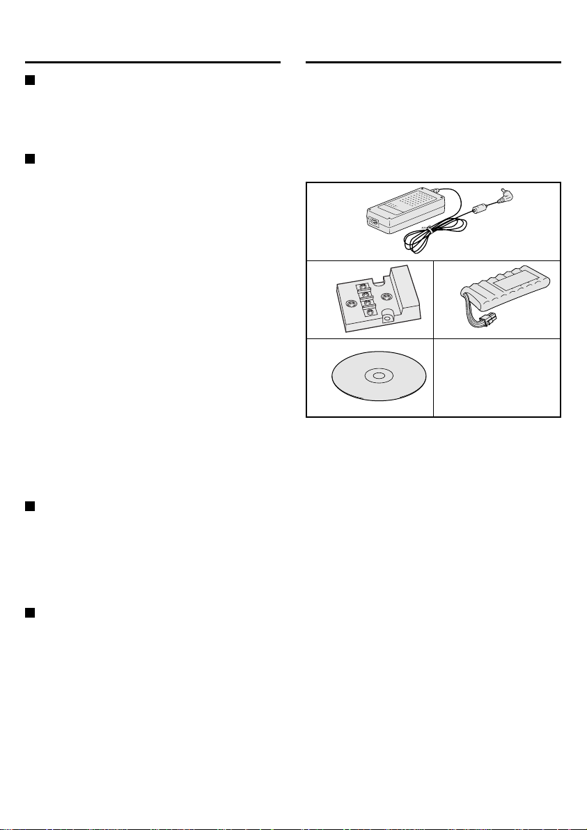
ACCESSORIES
Equipped with a 3.5-inch hard disk
The images are recorded directly to the camera’s
hard disk. The saved images can then be
manipulated using a CompactFlash card and a
personal computer.
The following four recording modes are
available.
Pre-alarm recording
•
This is normal recording. The images are saved
in the pre-alarm area of the hard disk.
Post-alarm recording
•
When a hold-up switch which is connected to
the H (HOLD-UP) terminal at the rear of the
camera is operated, post-alarm recording starts,
and the recorded images are saved in the
post-alarm area of the hard disk.
Backup recording
•
If there is 20 minutes or more of available
recording time remaining in the alarm recording
area of the hard disk when the first post-alarm
recording session ends, backup recording then
starts.
Suspicion recording
•
When a suspicion switch which is connected to
the S (SUSPICION) terminal at the rear of the
camera is operated, images such as those of
suspicious individuals are saved in the suspicion
area of the hard disk.
Multi-playback function
The captured images in hard disk can then be
played back in an instant. Special playback
functions such as multi-screen display, reverse
playback, frame jogging and zooming are all
possible. In addition, images can easily be copied
(saved) as required.
RS-232C connector/USB connector equipped
as standard
A computer can be connected to allow image data
to be transmitted at high speeds.
1 AC adaptor
2 Relay connector
3 Ni-Cd battery (for backup)
4 Application software (CD-ROM)
a Power cord
1
23
4
English 5
PART NAMES AND FUNCTIONS
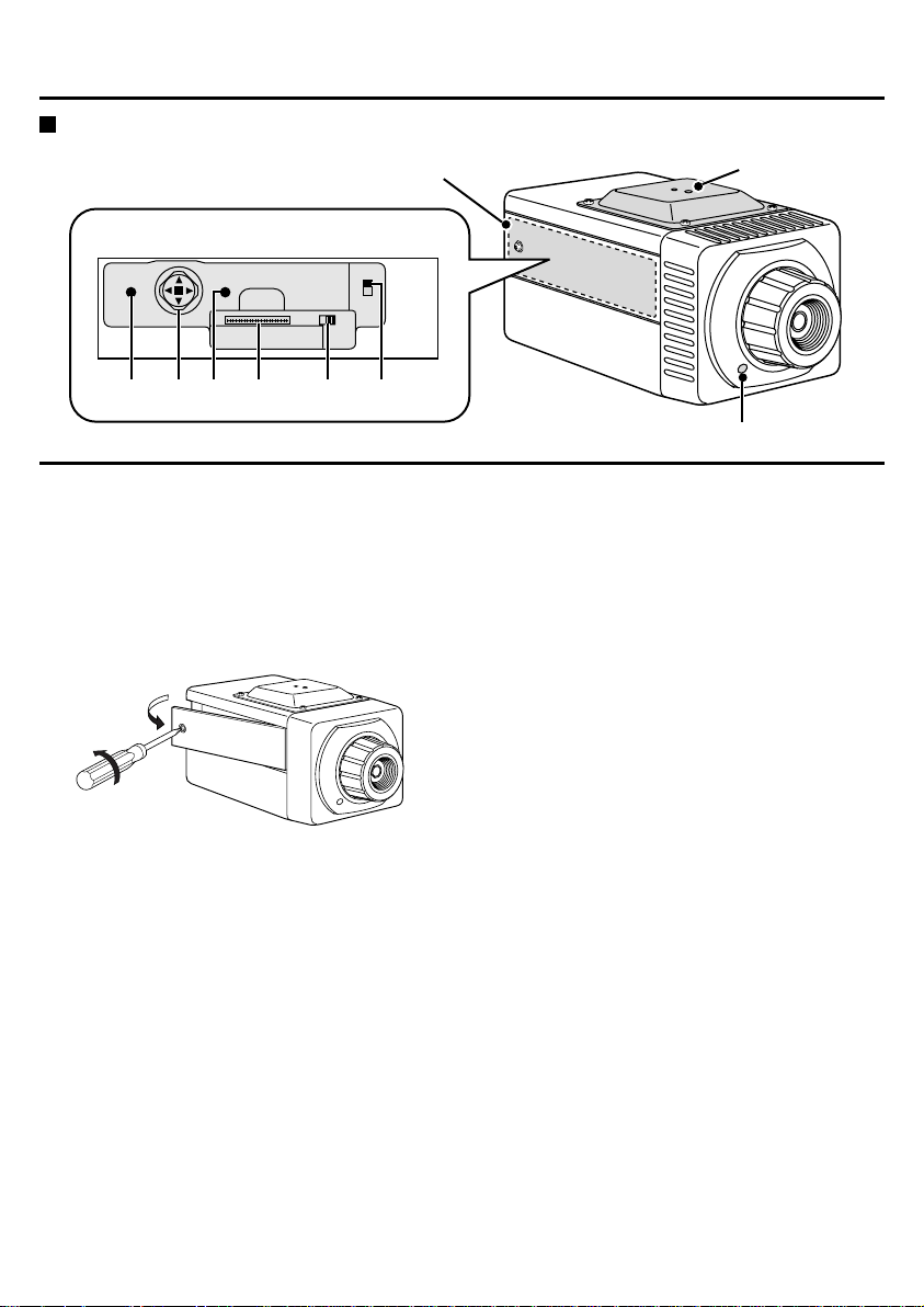
Front panel
2
SETMENU
1
23 4 6
NTSC
PAL
5
1 Operation panel cover
Remove this cover in order to use the MENU
button and CURSOR button to operate the
camera.
Removing the operation panel cover
•
Use a screwdriver to loosen the fixing
screws, and then slide the operation panel
cover to the left to remove it.
Note: Be careful not to drop the operation panel
cover when removing it.
1
4
2 Operation panel
1 MENU button
This button is used to display menu screens.
2 CURSOR button
This button is used to select items in the
menu screens and to change settings.
In addition, it is used to select images to be
played back and to select playback functions.
3 SET button
This button is used to accept items selected
in the menu screens and setting values.
4 Extension port
This port is used to copy images to
removable media such as a CompactFlash
card.
5 EJECT button (See page 70)
6 NTSC/PAL select switch
This switch is used to select the video format.
NTSC: NTSC format
PAL: PAL format
Note: This switch must be set before the power is
turned on. If it is set after the power is
turned on, the setting will be ignored.
3
6 English
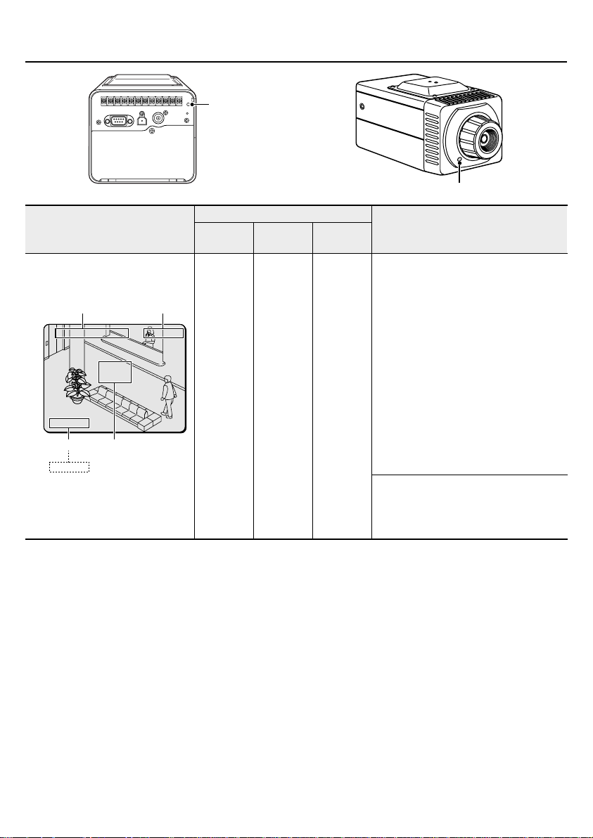
PART NAMES AND FUNCTIONS
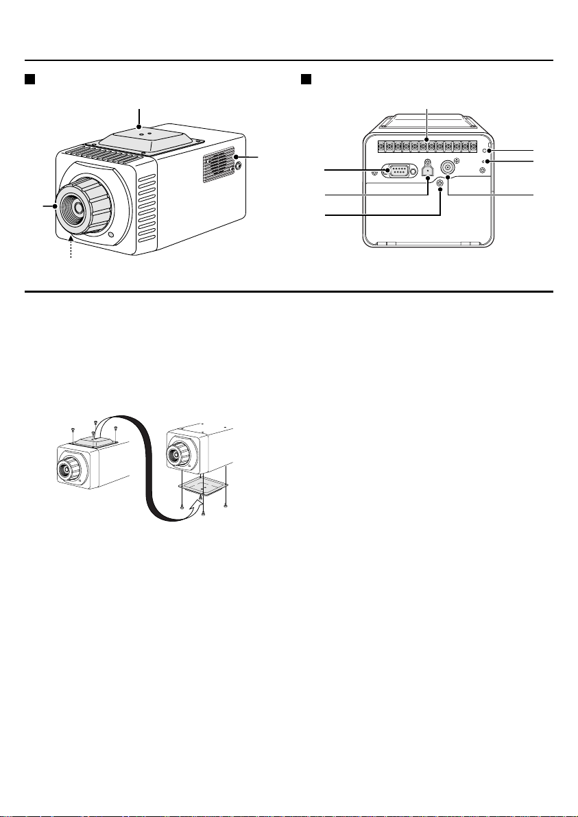
Front Panel Rear Panel
3
6
5
4
3 Camera mounting bracket
The camera mounting bracket is provided with
mounting holes (1/4” – 20 UNC). At the time of
shipment from the factory, the bracket is attached
to the top of the camera, but it can also be
attached to the bottom of the camera. Use
whichever attachment position is suitable for the
place and method of use.
Note: If installing the camera to a ceiling, always be
sure to check the strength of the installation
location (it must be able to bear a weight of at
least 10 kg). It is recommended that you use
the model VA-WH-1 mounting bracket (sold
separately) to install the camera. Contact the
place where you purchased the camera for
further details.
4 Caution indicator (See page 9)
Flashes or lights to indicate the operating status of
the camera.
5 Lens
6 Cooling fan
A cooling fan is provided in order to prevent the
inside of the camera from overheating.
If the cooling fan stops, stop the camera and check
the cause of the problem.
English 7
1
2
3
4
1 Control terminals
These terminals are used to connect extra items
such as hold-up and suspicion switches, a
warning indicator or a 13.8 V DC power supply.
2 RS-232C connector (RS-232C)
This connector is used to connect the camera to
a computer in order to transfer images from the
camera to the computer.
3 USB connector (USB)
This connector is used to connect a computer in
order to transfer images from the camera to the
computer.
If the RS-232C connector and USB connector
are both connected at the same time, the USB
connector has priority for image data transfer.
4 Rear cover fixing screw
This screw is used when replacing the hard disk
or the Ni-Cd backup battery.
7
6
5
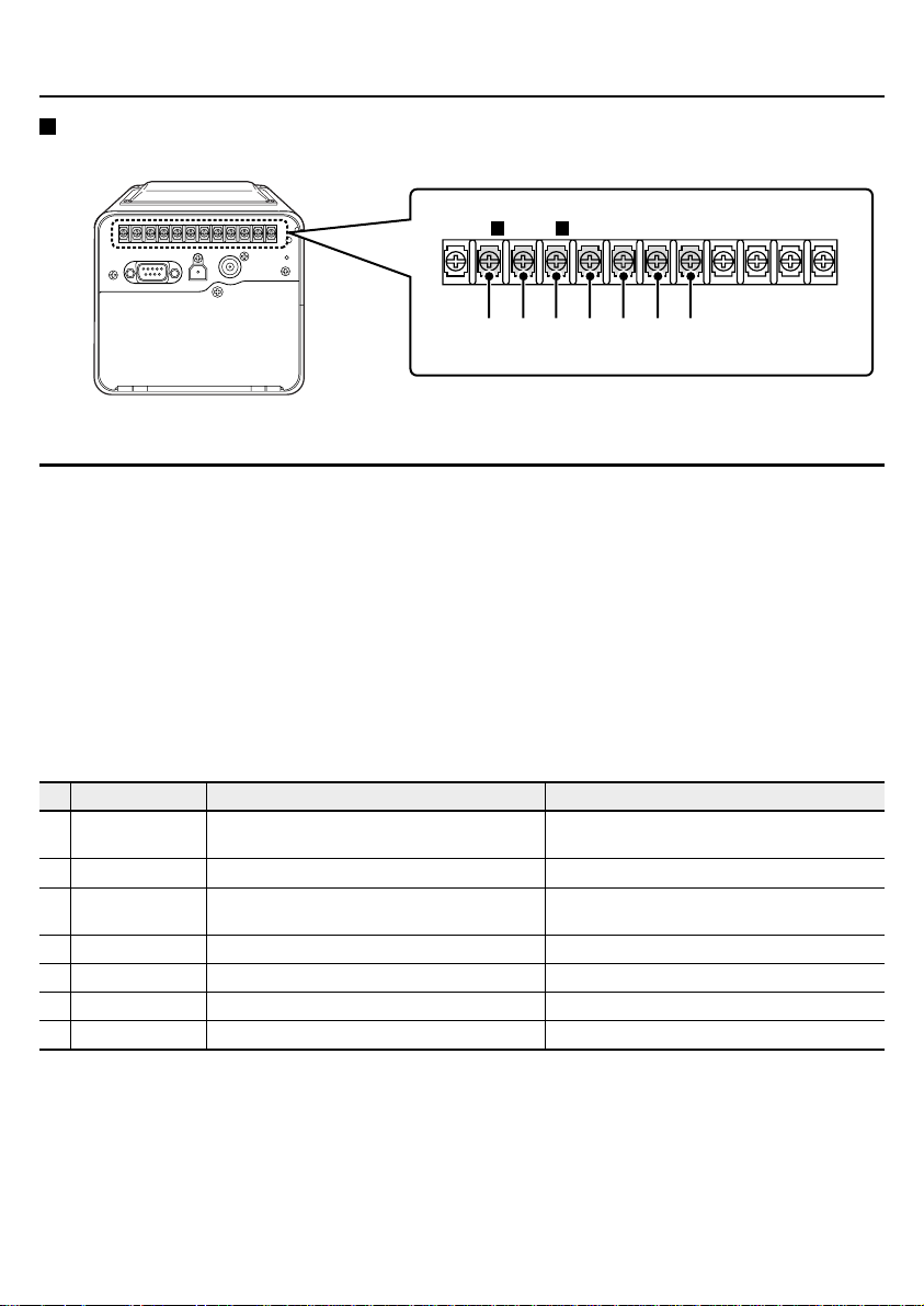
Control terminals
WARNING
S
H
GND GND GND
DC13.8V
1 2 3 4 5 6 7
5 VIDEO OUT terminal (BNC plug)
This terminal is used to connect the camera to a
component such as a monitor or camera control
unit.
6 RESET button
Press the RESET button if an abnormality occurs
with the camera. Settings are not changed
when the camera is reset in this way.
Terminal Signal Input/output voltage
1 H (HOLD-UP) Alarm switch input signal 2.5 V or higher when alarm switch off/
2 GND Alarm switch and suspicion switch ground 0 V
3 S (SUSPICION) Suspicion switch input signal 2.5 V or higher when suspicion switch off/
4 GND Warning ground 0 V
5 WARNING Warning signal output 3.3 V or higher when warning generated
6 GND Power supply ground 0 V
7 DC 13.8 V Power supply input 13.8 V DC
7 Warning indicator
The warning indicator lights when the
•
camera power is turned on.
It flashes when there is a hard disk error or if
•
there is a problem with the backup battery.
0.4 V or lower when alarm switch on
0.4 V or lower when suspicion switch on
8 English
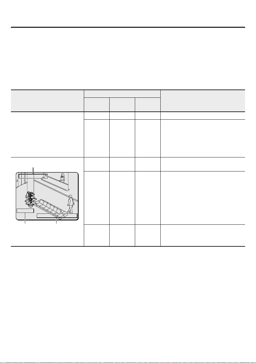
WARNING DISPLAYS
There is a caution indicator and a warning indicator on the front and back of the camera. These indicators
operate to notify you of the operating status of the camera and of any cautions and warnings. In addition,
text messages indicating warnings are also displayed on the monitor screen in conjunction with the flashing
speed of the indicators.
A separate indicator can be connected to the WARNING terminal to let you check the same warning statuses
as shown by the built-in warning indicator.
If the warning indicator continues flashing, it indicates that there is a problem with the camera.
If this happens, maintain the camera in the same status and contact the place of purchase.
Indicator
Monitor display
Warning
Off Off Off Hard disk at standby
Lights Lights Off
1
PRE2 ALARM-REC PRE2 ALARM-REC
PRE2 ALARM-REC
Lights Fast
Slow
flashes
FUN WARN FUN WARN
FUN WARN
<SUSPICION REC FULL> <SUSPICION REC FULL>
<SUSPICION REC FULL>
32
Slow
flashes
Caution
Caution
(ON)
Off During suspicion recording
flashes
Lights Off
Slow
flashes
Off
(OFF)
When MAIN MENU screen displayed
When SETTINGS screen displayed
During playback
During pre-alarm or post-alarm
recording
1 When post-alarm recording is
2 When the cooling fan has stopped
3 When suspicion recording is
When computer connected
When computer connected
(during data transmission) (ö)
Camera status
complete and pre-alarm 2
recording has started (suspicion
recording possible)
(alarm/suspicion recording possible)
complete (alarm recording possible)
English 9
Warning indicator
Caution indicator
Indicator
Monitor display
4
<ALARM REC FULL> HDD WARN
<ALARM REC FULL> HDD WARN <ALARM REC FULL> HDD WARN
SYSTEM
SYSTEM SYSTEM
ERROR
ERROR ERROR
6
Warning
Fast
flashes
LOW BATT LOW BATT
LOW BATT
7
NO BATT
5
Caution
(ON)
Fast
flashes
Caution
(OFF)
Off
4 When there is 20 minutes or less of
5 When there is a problem with the
6 When there is a problem with the
7 When Ni-Cd battery is not installed
Camera status
recording time remaining in the
post-alarm recording area, or
When post-alarm 2 recording is
complete (suspicion recording
possible)
camera hardware (recording is not
possible)
hard disk (recording is not possible)
or not connected (NO BATT)
When there is a problem with the
Ni-Cd battery (LOW BATT)
When time setting has not been
carried out
During hard disk initialization (ö)
During memory card initialization
Note: If you do not need the caution indicator to operate (lighting or flashing), you can set it to remain off
at all times by setting CAUTION LED to “OFF” in the SYSTEM SET screen.
However, the ö mark indicates times when the caution indicator flashes regardless of the CAUTION
LED setting.
10 English

INSTALLING AND HANDLING
THE Ni-Cd BACKUP BATTERY
The Ni-Cd battery which is supplied with the camera is used as a backup power supply for the clock and the
hard disk.
The battery has not been charged. Before turning on the camera power, install the battery by referring to the
points below. If any problems with battery operation or leakages of battery fluid occur, contact the place of
purchase.
Note:
Once the camera’s power has been turned on
•
and left on for 24 hours, the battery will be
charged sufficiently to provide 30 days of
backup operation.
If the battery is used continuously for long
•
periods, leakage of battery fluid may occur. The
interior of the battery compartment is lined with
absorbent material to absorb any fluid which
should happen to leak from the battery, so if
replacing the battery after a leak has occurred,
be sure to replace this absorbent material also.
Always be sure to use the accessory AC
•
adapter. If you use some other
commercially-available AC adapter, detection of
problems with the backup battery will not be
possible, and damage to the hard disk may
result.
If the camera power supply is turned off or a
•
power outage occurs after the battery has only
been charging for a short time, it may cause the
clock setting to be re-initialized. If this happens,
the camera will not operate.
(Warning displays)
When the camera power is turned on after the
•
battery has been replaced, “LOW BATT” will
appear on the monitor screen, and charging of
the battery will start automatically.
Approximately 1 hour of charging time is
•
needed before the “LOW BATT” display
disappears from the monitor screen. If the
“LOW BATT” display does not disappear after
one hour or more has passed, it may indicate a
problem with the battery.
If “LOW BATT” appears on the monitor screen
•
while the camera is in use, the warning
indicator will flash and recording of images will
be halted. This may also indicate a problem with
the battery, so replace the battery at such times.
If the battery has not been installed, or if the
•
battery terminal contacts are not complete,
“NO BATT” will appear on the monitor display.
If this happens, check the battery once more.
English 11
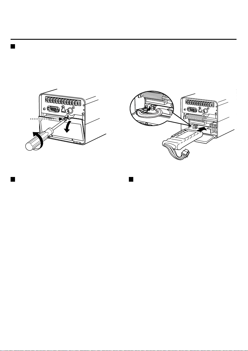
Installing the Ni-Cd battery
1 Loosen the rear cover fixing screw (A) and open
the cover. (The screw cannot be removed from
the cover.)
2 Insert the battery into the battery compartment
so that the Ni-Cd battery label is facing upward.
A
3 Connect the battery plug to the connector.
4 Close the rear cover and tighten the rear cover
fixing screw (A).
3
1
WARNING
Do not short the battery terminals and do not
•
attempt to disassemble or modify the battery.
Do not drop the battery or subject it to strong
•
shocks.
Do not place the battery into fire, as it may
•
explode.
Do not expose the battery to moisture.
•
Do not place the battery into water or let the
•
terminals of the battery get wet.
2
DANGER
The following precautions must be observed at all
times, otherwise the battery may leak, overheat or
explode.
Never peel off or scratch the outer tube.
•
Do not use in any other appliance except for
•
this camera.
Do not carry the battery by holding the
•
connectors or lead wires.
If the fluid inside the battery gets into eyes, it may
cause blindness. Do not rub the eyes, wash the
affected area immediately with clean water, and
then seek medical advice.
If the fluid inside the battery gets onto the skin or
clothing, it may injure the skin, so wash the
affected area immediately with clean water.
12 English
CONNECTIONS
Carefully read the documentation which is provided with each of the components being connected.
Be careful to connect components correctly, as incorrect connections could cause fire or other damage.
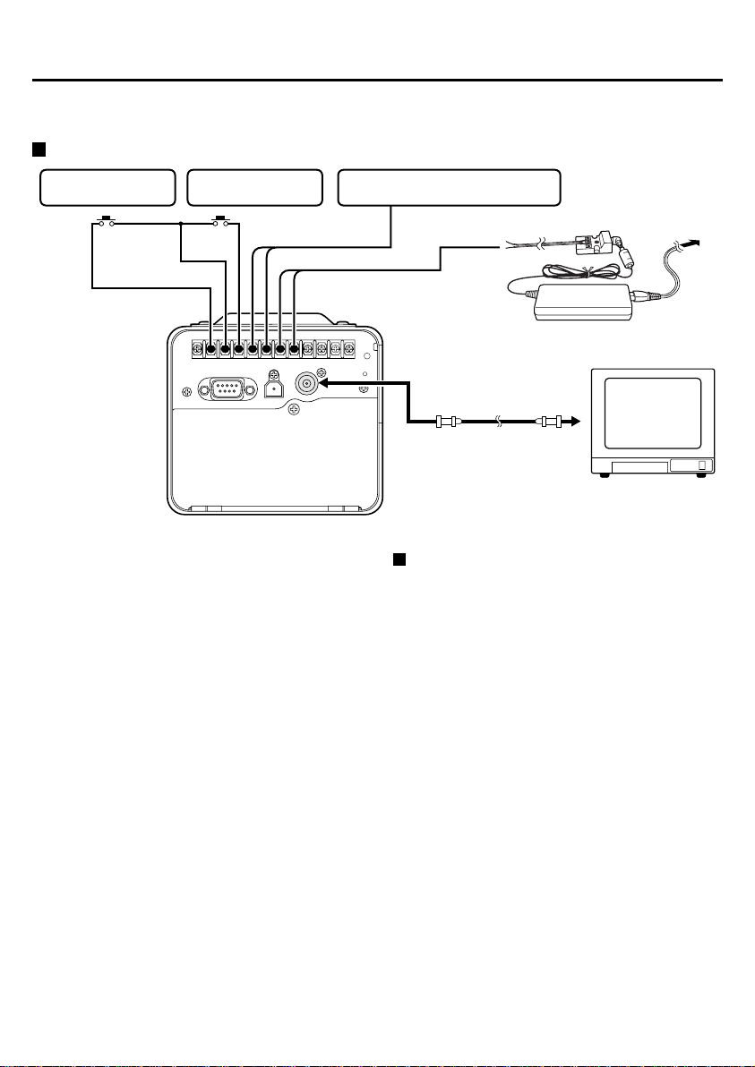
Basic connections
(A) Hold-up switch
(B) Suspicion switch
(C) Warning signal check output
(connect a lamp or similar device)
1
2
Connect all required devices to the control
terminals before turning on the power.
(A) Connect a commercially-available hold-up
switch (H/GND).
(B) Connect a commercially-available suspicion
switch (S/GND).
(C) Connect a commercially-available monitoring
lamp to the warning signal output terminal.
This will light or flash in the same way as the
warning indicator on the rear of the camera
for checking purposes.
13.8 V DC
Coaxial cable
To VIDEO IN
Connecting the power supply
3
TV monitor
(sold separately)
1 Connect a commercially-available cable to the
relay connector (supplied), and then connect
the cable to the power supply connector (13.8
V/GND) of the camera.
2 Insert the plug of the AC adaptor (supplied) into
the relay connector terminal.
3 Insert one end of the power cord (supplied) into
the AC adaptor, and insert the other end into a
wall outlet.
Note:
The cable that is connected to the relay
•
connector can be up to a maximum of 30
meters in length, but it should not be bound up
with any other cables.
Use UL NISPT-2 (2/18AWG, 105˚CM, VW-1)
•
cables which are listed in UL as the connection
cables.
English 13
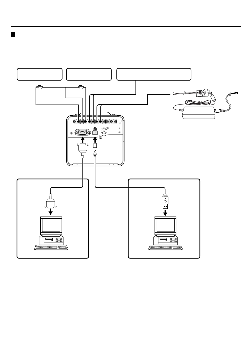
Connection to a computer
If the camera is connected to a computer, you can then use the accessory application software to perform
operations such as data transfer and printing of images by the computer.
The method of connecting the power supply and peripheral devices is the same as described in “Basic
connections”.
(A) Hold-up switch (B) Suspicion switch
(C) Warning signal check output
(connect a lamp or similar device)
1
2
13.8 V DC
•
RS-232C cable connection
Computer
Note:
When connecting an RS-232C cable, it may be necessary to use a separate conversion adaptor depending
•
on the type of computer being used.
When connecting a USB cable, take note of the differences in the shapes of the connectors at the
•
computer end and at the camera end.
Only connect a cable to the USB connector when using the application software. If the USB cable is
•
connected to the camera at other times, normal operations such as recording cannot be carried out.
•
USB cable connection
Computer
3
14 English
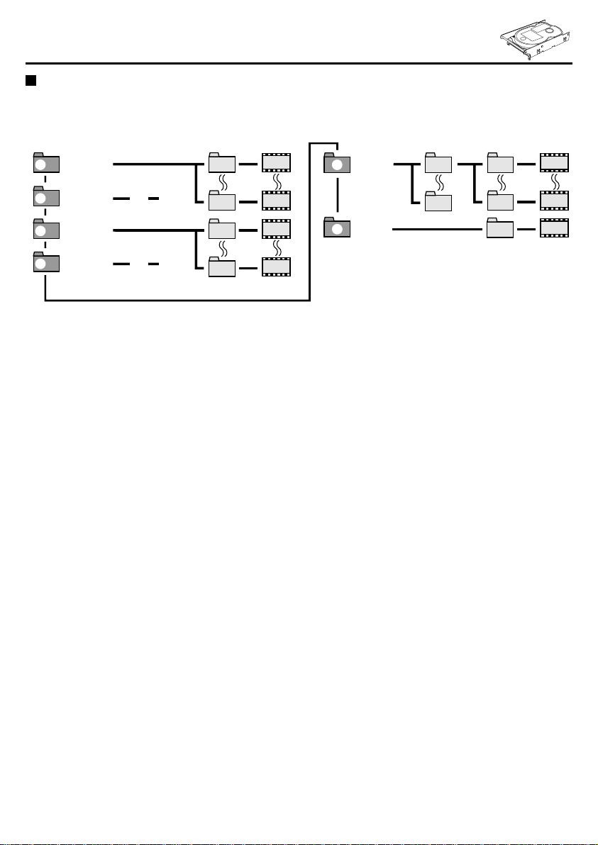
HARD DISK
Hard disk recording areas
The camera records the images being viewed onto the hard disk.
The hard disk is divided into six areas (1 ~ 4). The folder and file structure on the hard disk is as shown
below.
PRE1 ALM
1 5
-A
-A
PRE2 ALM
1
-B
2
2
-B
-A
-A
-B
-B
POST1 ALM
POST2 ALM
5
F
6
6
F
1 Pre-alarm recording area
A PRE1 ALM: Pre-alarm images are recorded.
B PRE2 ALM: Backup pre-alarm images are
recorded.
2 Post-alarm recording area
A POST1 ALM: Post-alarm images are
B POST2 ALM: Backup post-alarm images
recorded.
are recorded.
3 Suspicion recording area
Images are recorded in this area during
suspicion recording.
4 Archiving area
This area is used to store copies of images
which have been recorded during alarm
playback and suspicion playback.
5 Pre-alarm recording image folders
(PRE1, 2 ALM)
A new folder is created every five minutes.
6 Post-alarm recording image folders
(POST1, 2 ALM)
A new folder is created every five minutes.
F
F
SUSPECT
3 7
ARCHIVE
4
7 Suspicion recording image folder 1
If the number of images saved in image folder 2
during suspicion recording reaches 99, then the
next image folder 1 is created.
8 Suspicion recording image folders 2
A new image folder 2 is created each time
suspicion recording is carried out. Up to 99
image folders can be created.
9 Archiving image folders
This folder is used to store copies of images
which have been recorded during alarm
playback and suspicion playback.
F Pre-alarm and post-alarm recorded image
files (PRE1, 2 ALM, POST1, 2 ALM)
Image files recorded during a five-minute period
are saved in a single one of these folders.
G Suspicion recording image files (SUSPECT)
Up to 900 image files (1 FPS: 15 minutes, 3FPS:
5 minutes) are created during suspicion
recording. Once 900 images have been saved,
the next image folder 2 is created.
H Archive recorded image files (ARCHIVE)
Only one image folder is created in the archive
recording area. Up to 500 archive recording
images can be created and stored in this image
folder.
8
9
G
H
English 15

Protecting the hard disk
When you have finished using the camera, set the
hard disk to standby mode before turning off the
power. If the camera power is turned off at the
following times when recording or playback is in
progress, damage to the hard disk may result. (See
page 18)
When the Ni-Cd battery has not been charged
•
for long enough
When camera operation is stopped immediately
•
after the battery has been replaced
Checking the hard disk
A hard disk check is carried out automatically when
the camera power is turned on in order to see if
there are any problems with the formatting of the
hard disk. If a problem with the hard disk is
detected, “CHECKING DISK!” is displayed on the
monitor screen. If this happens, reformat the hard
disk, or if the hard disk contains images that you
need to save, contact the place of purchase for
assistance.
The hard disk is sensitive to dust, vibration and
shocks, and it should also not be used in the vicinity
of items which generate magnetic fields. Be sure to
observe the following in order to minimize the risk
of data losses.
Do not subject the hard disk to shocks.
•
Do not use the camera in places which are
•
unstable or subject to vibration.
Do not move the camera while the power is still
•
turned on.
Do not disconnect the power cord from the
•
power supply while recording or playback is in
progress.
Do not use the camera in places which are
•
prone to sudden changes in temperature
(changes of more than 10˚C in one hour).
If moving the camera to a place which has high
•
humidity or which is subject to large fluctuations
in humidity, condensation may form inside the
camera. If the camera is used while there is
condensation inside the camera, it may result in
camera malfunctions.
Do not install the camera in places which are
•
subject to vibration, such as inside vehicles or
trains.
The built-in hard disk, cooling
fan and Ni-Cd battery are
consumable.
These parts should generally be replaced after 2
•
years of operation at an ambient temperature
of 25˚C. This replacement period is a guide
only, and is not a guarantee that performance
will be maintained during the whole of the time.
If the ambient temperature is 40˚C, the Ni-Cd
•
battery should generally be replaced after one
year.
16 English
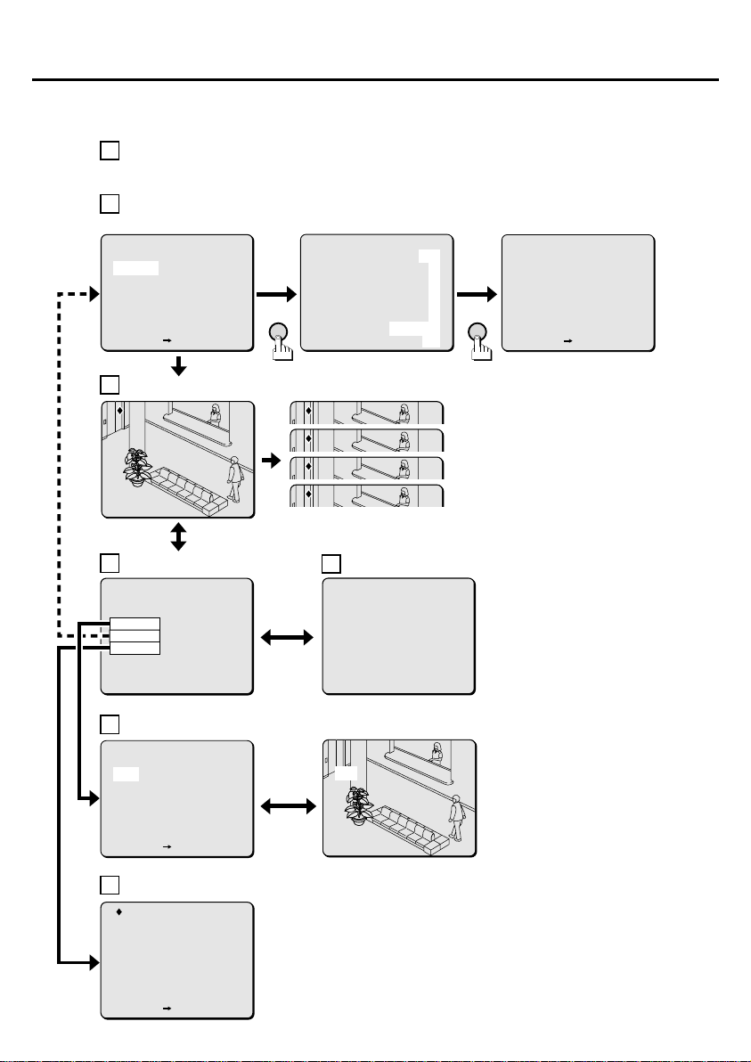
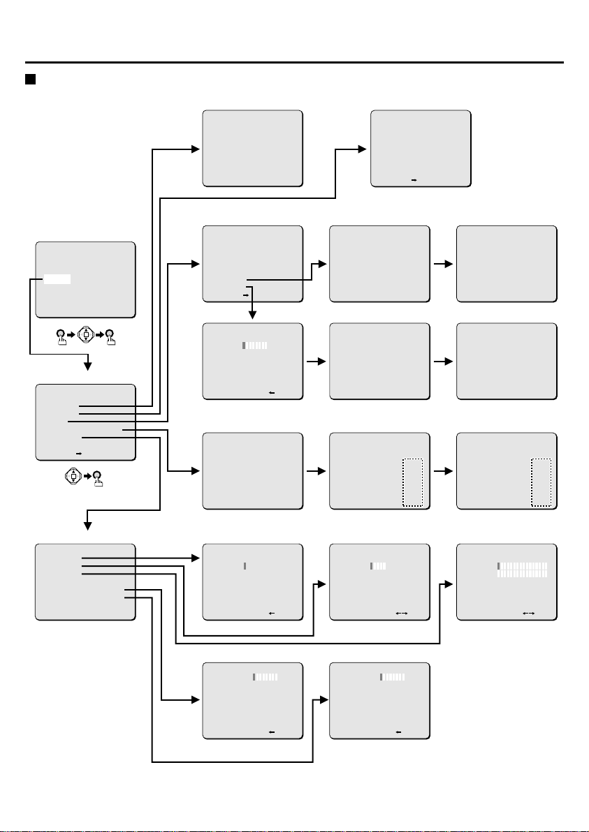
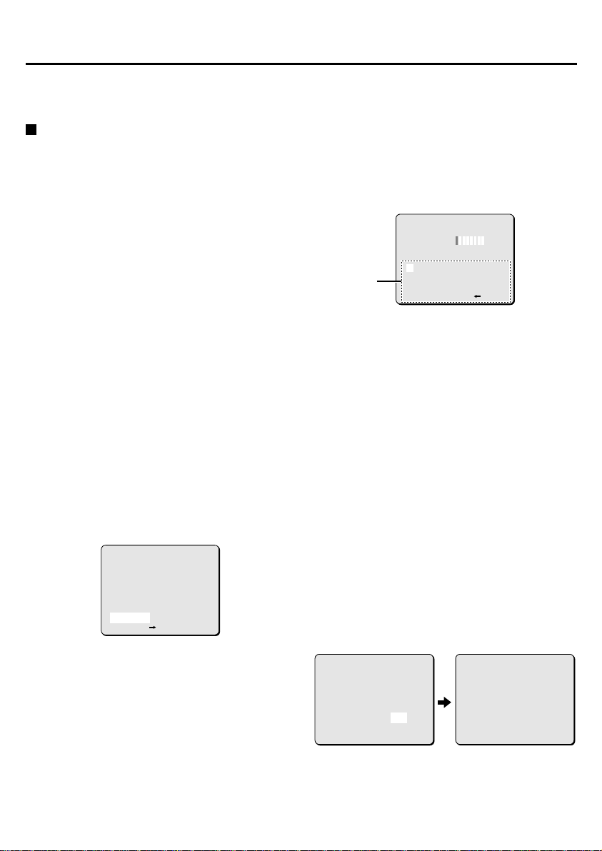
FROM RECORDING TO PLAYBACK
POST1-ALARM REC POST1-ALARM REC POST1-ALARM REC
PRE2-ALARM REC PRE2-ALARM REC PRE2-ALARM REC
POST2-ALARM REC POST2-ALARM REC POST2-ALARM REC
SUSPICION REC SUSPICION REC SUSPICION REC
When using this camera for recording and playback for the first time, follow the steps given below. Refer to
the reference pages given for more details on each step.
Turn on the power. (See page 1 3)
1
The camera itself does not have a power switch. Connect the accessory AC adaptor and
relay connector, and then insert the power plug into a wall outlet.
Set the date and time. (See page 22)
2
Recording is not possible until the time has been set.
(SETTINGS)
CLOCK SET
SYSTEM SET
HDD SET
SUMMER TIME/DAYLIGHT SET
KEY WORD SET
[MENU] (MAIN MENU)
Record the images. (See page 39)
3
PRE1-ALARM REC PRE1-ALARM REC
PRE1-ALARM REC
REMAIN SHOTS:6834 REMAIN SHOTS:6834
REMAIN SHOTS:6834
(CLOCK SET)
YEAR------------------2002
MONTH----------------- 08
DAY------------------- 02
HOUR------------------ 15
MINUTE---------------- 15
SET SET
SECOND---------------- 20
FORM------------MM/DD/YYYY
CLOCK START----------- YES
(CLOCK START)
08/02/2002 15:15:20
[MENU] (SETTING)
Selection
4
(MAIN MENU)
RECORD START
PLAYBACK
SETTINGS
CONDITION
Play back the recorded images. (See page 49)
5
(PLAYBACK)
ALARM
SUSPICION
ARCHIVE
EXTENSION
[MENU] (MAIN MENU)
View details of the time and the hard disk recording capacity. (See page 37)
6
CONDITION
TIME: 08/02/2002 15:15:20
PRE: 15MIN POST: 30MIN
SUSPICION: 150/ 6834PCS
FRAMERATE: 3FPS ST/DL:OFF
FILE ID: A ID:
COMMENT:
[MENU] (MAIN MENU)
English 17
Set the hard disk to the standby condition when you
7
have finished using the camera. (See page 18)
DISK CLOSING
(FUNCTIONS)
(FUNCTIONS) (FUNCTIONS)
ZOOM
ZOOM ZOOM
ON SCREEN DISPLAY
ON SCREEN DISPLAY ON SCREEN DISPLAY
COPY
COPY COPY
DELETE
DELETE DELETE
2001/08/02 13:42:35 1/3 2001/08/02 13:42:35 1/3
2001/08/02 13:42:35 1/3
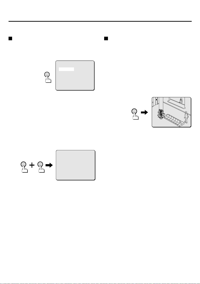
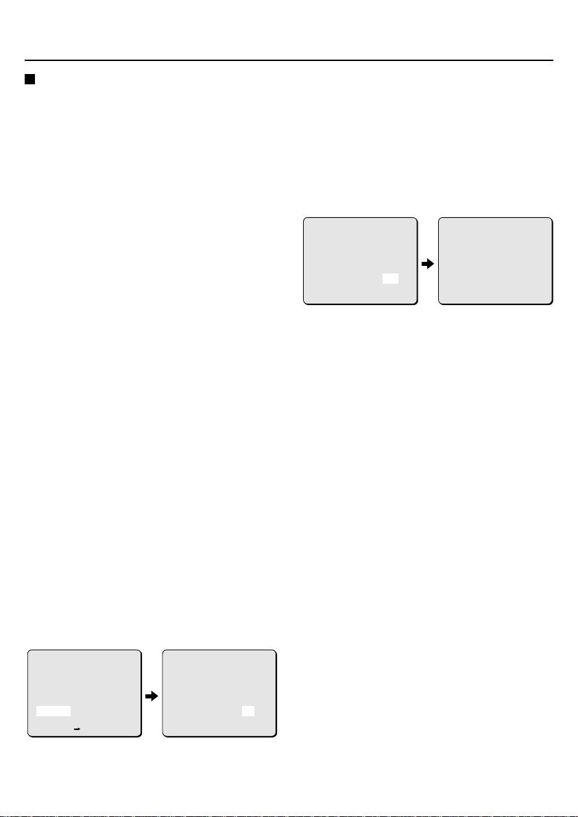
HARD DISK STANDBY MODE
When shooting or recording ends, switch the hard disk to standby mode.
Setting to standby mode
1 Press the MENU button.
The MAIN MENU screen will be displayed.
(MAIN MENU)
RECORD START
MENU
PLAYBACK
SETTINGS
CONDITION
2 While pressing the MENU button, press
the SET button.
After the current image has been recorded on
the hard disk, the disk will change to standby
mode. During recording, the message “DISK
CLOSING” will be displayed for approximately
2 seconds.
Furthermore, the warning indicator and
caution indicator will both switch off while the
hard disk is in standby mode.
MENU SET
DISK CLOSING
Canceling standby mode
If you press the MENU button, the MAIN MENU
screen will be displayed.
To start pre-alarm recording, select RECORD START
and then press the SET button. Furthermore, if the
MAIN MENU screen remains displayed for 30
seconds, the camera will change automatically to
pre-alarm recording.
Press the MENU button.
Pre-alarm recording will then start.
PRE1-ALARM REC
PRE1-ALARM REC PRE1-ALARM REC
MENU
REMAIN SHOTS: 6834 REMAIN SHOTS: 6834
REMAIN SHOTS: 6834
Note: The warning indicator and caution indicator
will both flash while the hard disk contents
are being checked. When pre-alarm
recording starts, the caution indicator will
light.
Note:
The caution indicator will flash until the hard
•
disk changes to standby mode. None of the
setting details will change when the hard disk is
in standby mode.
This operation (DISK CLOSING) cannot be
•
carried out using the camera control unit (sold
separately).
18 English

MEMO.....................................................
................................................................
................................................................
................................................................
................................................................
................................................................
................................................................
................................................................
................................................................
................................................................
................................................................
................................................................
................................................................
................................................................
................................................................
................................................................
English 19
MENU SETTINGS
MENU SETTINGS
Menu screen display
b Clock settings
(CLOCK SET)
YEAR------------------2001
MONTH----------------- 01
DAY------------------- 01
HOUR------------------ 13
MINUTE---------------- 59
SECOND---------------- 59
FORM------------MM/DD/YYYY
CLOCK START----------- YES
b Hard disk area capacity setting
MAIN MENU screen
(MAIN MENU)
RECORD START
PLAYBACK
SETTINGS
CONDITION
(HDD SET)
<SUSPICION SHOTS: 6834PCS>
<ALARM TIME 45MIN>
<PRE ALARM 15MIN>
<POST ALARM 30MIN>
SPACE SET
INITIALIZE
[MENU] (MAIN MENU)
b System settings
(SYSTEM SET)
BLC CONTROL ------- OFF
CAUTION LED ------- ON
SUSPICION FRAMERATE 3 FPS
SUSPICION LOOP ---- OFF
FLICKER LESS ------ OFF
[MENU] (SETTINGS)
(SPACE SET)
<SUSPICION SHOTS: 6834PCS>
<ALARM TIME 45MIN>
PRE ALARM 15 MIN
POST ALARM 30 MIN
SETUP YES
(SPACE SET)
<SUSPICION SHOTS: 6834PCS>
<ALARM TIME 45MIN>
PRE ALARM 15 MIN
POST ALARM 30 MIN
SETUP YES
DO NOT POWER OFF!
SETTING NOW!
MENU SET
SETTINGS screen
(SETTINGS)
CLOCK SET
SYSTEM SET
HDD SET
SUMMER TIME/DAYLIGHT SET
KEYWORD SET
[MENU] (MAIN MENU)
SET
b Keyword settings
(KEY WORD SET)
FILE ID :A
CAMERA ID:
COMMENT :
CHANGE PASSWORD (DELETE)
CHANGE PASSWORD (INITIAL)
(INITIALIZE)
PASSWORD:
ABCDEFGHIJKLM
NOPQRSTUVWXYZ
0123456789
BS END
(HDD INITIALIZE)
<SUSPICION SHOTS: 6834PCS>
<ALARM TIME 45MIN>
PRE ALARM 15 MIN
POST ALARM 30 MIN
INITIALIZE YES
b Summer time/daylight settings
(SUMMER TIME/DAYLIGHT SET)
MODE ----------------- OFF
(START) (END)
WEEK 1ST LAST
SUN SUN
MONTH 04 10
HOUR 02 02
MINUTE 00 00
(KEY WORD SET)
FILE ID :
ABCDEFGHIJKLM
NOPQRSTUVWXYZ
0123456789
BS END
(CHANGE PASSWORD-DELETE)
OLD PASSWORD:
NEW PASSWORD:
VERIFICATION:
ABCDEFGHIJKLM
NOPQRSTUVWXYZ
0123456789
BS END
(SUMMER TIME/DAYLIGHT SET)
MODE ----------------- ON
(START) (END) START
WEEK 1ST LAST 1ST
SUN SUN SUN
MONTH 04 10 04
HOUR 02 02 02
MINUTE 00 00 00
(KEY WORD SET)
CAMERA ID:
ABCDEFGHIJKLM
NOPQRSTUVWXYZ
0123456789.,
/-$&#’”()
(CHANGE PASSWORD-INITIALIZE)
OLD PASSWORD:
NEW PASSWORD:
VERIFICATION:
ABCDEFGHIJKLM
NOPQRSTUVWXYZ
0123456789
BS END
END
(HDD INITIALIZE)
<SUSPICION SHOTS: 6834PCS>
<ALARM TIME 45MIN>
PRE ALARM 15 MIN
POST ALARM 30 MIN
INITIALIZE YES
DO NOT POWER OFF!
INITIALIZING NOW!
(SUMMER TIME/DAYLIGHT SET)
MODE ---------------- ON
(START) (END) END
WEEK 1ST LAST LAST
SUN SUN SUN
MONTH 04 10 10
HOUR 02 02 02
MINUTE 00 00 00
(KEY WORD SET)
COMMENT :
ABCDEFGHIJKLM
NOPQRSTUVWXYZ
0123456789.,
/-$&#'”()
END
English 21
SETTING THE CLOCK (CLOCK SET)
You need to set the date and time in order to use the camera. The recording functions of this camera cannot
be used if the date and time have not been set. In addition, if the accessory Ni-Cd battery (for backup) which
is used for running the clock and for hard disk backups has been replaced, you must reset the clock.
The setting time is displayed when “CONDITION” is selected from the MAIN MENU screen.
•
CONDITION
TIME: 08/02/2002 15:34:26
PRE: 15MIN POST: 30MIN
SUSPICION: 150/ 6834PCS
FRAMERATE: 3FPS ST/DL: ON
FILE ID: A ID:
COMMENT:
[MENU] (MAIN MENU)
Note: The clock is set when the camera is first
used, but if summer time has been set, the
time will advance by one hour automatically
during the summer time application period,
so you may need to reset the clock.
Setting example: To set the clock to 15:15:20
Press the MENU button to return to the SETTING
screen.
on 2 August 2002
5 Use the CURSOR (l) button to select
“DAY ... 01” and then use the CURSOR (d
or c) button to set the day to “02”.
6 Use the CURSOR (l) button to select
“HOUR ... 00” and then use the CURSOR
(d or c) button to set the hour to “15”.
7 Use the CURSOR (l) button to select
“MINUTE ... 00” and then use the CURSOR
(d or c) button to set the minutes to
“15”.
8 Use the CURSOR (l) button to select
“SECOND ... 00” and then use the CURSOR
(d or c) button to set the seconds to
“20”.
1 Use the CURSOR (l) button to select
“SETTINGS” and then press the SET button.
The SETTINGS screen will be displayed.
2 Use the CURSOR (l) button to select
“CLOCK SET” and then press the SET
button.
The CLOCK SET screen will be displayed.
(CLOCK SET)
YEAR------------------2001
MONTH----------------- 01
DAY------------------- 01
HOUR------------------ 00
MINUTE---------------- 00
SECOND---------------- 00
FORM----------- MM/DD/YYYY
CLOCK START----------- YES
(Before setting) (After setting)
(CLOCK SET)
YEAR------------------2002
MONTH----------------- 08
DAY------------------- 02
HOUR------------------ 15
MINUTE---------------- 15
SECOND---------------- 20
FORM----------- MM/DD/YYYY
CLOCK START----------- YES
3 Use the CURSOR (l) button to select
“YEAR ... 2001” and then use the CURSOR
(d or c) button to set the year to “2002”.
4 Use the CURSOR (l) button to select
“MONTH ... 01” and then use the CURSOR
(d or c) button to set the month to “08”.
9 Use the CURSOR (l) button to select
“FORM ... MM/DD/YYYY” and then use
the CURSOR (d or c) button to set the
desired format.
YYYY/MM/DD: Year/Month/Day
•
MM/DD/YYYY: Month/Day/Year
•
DD/MM/YYYY: Day/Month/Year
•
10 Use the CURSOR (l) button to select
“CLOCK START ... YES” and then press the
SET button.
The CLOCK START screen will be displayed,
and the date and time which have been set
will appear on the screen. The camera will
return to recording mode after approximately
30 seconds.
If you select “NO”, the clock setting will not
be changed, and the screen will return to the
SETTINGS screen.
(CLOCK START)
2002/08/02 15:15:20
22 English
SYSTEM SETTINGS (SYSTEM SET)
Several different system settings can be made as indicated below. When these settings are made, the screen
display appears as shown in the accompanying illustrations.
1 Setting the backlight compensation
2 Setting the front caution indicator to stay off
during recording
3 Changing the frame rate for suspicion recording
4 Setting the overwriting conditions and warning
displays or suspicion recordings
5 Changing the flickerless setting
3
PRE1-ALARM REC
PRE1-ALARM REC
REMAIN SHOTS:10000
REMAIN SHOTS:10000
4
Press the MENU button to return to the SETTING
screen.
SUSPICION
SUSPICION
FUNCTION
FUNCTION
2001/02/14 15:25:50 1/1
2001/02/14 15:25:50 1/1
SUSPICION
SUSPICION
FUNCTION
FUNCTION
REMAIN SHOTS:LOOP
REMAIN SHOTS:LOOP
REMAIN SHOTS:LOOP
1 Use the CURSOR (l) button to select
“SETTINGS” and then press the SET button.
The SETTINGS screen will be displayed.
2 Use the CURSOR (l) button to select
“SYSTEM SET” and then press the SET
button.
The SYSTEM SET screen will be displayed.
The various items can be selected by
•
pressing the SET button.
(SYSTEM SET)
BLC CONTROL ------- OFF
CAUTION LED ------- ON
SUSPICION FRAMERATE 3 FPS
SUSPICION LOOP ---- OFF
FLICKER LES ------- OFF
[MENU] (SETTINGS)
(Before setting) (After setting)
English 23
(SYSTEM SET)
BLC CONTROL ------- ON
CAUTION LED ------- OFF
SUSPICION FRAMERATE 1 FPS
SUSPICION LOOP ---- ON
FLICKER LES ------- ON
[MENU] (SETTINGS)
3 Use the CURSOR (l) button to select “BLC
CONTROL ... OFF” and then use the
CURSOR (d or c) button to select “ON”.
ON: Backlight compensation is carried out.
OFF: Backlight compensation is not carried
out.
4 Use the CURSOR (l) button to select
“CAUTION LED ... ON” and then use the
CURSOR (d or c) button to select “OFF”.
ON: The caution indicator lights.
OFF: The caution indicator stays switched off.
The screen display will also disappear during
recording.
5 Use the CURSOR (l) button to select
“SUSPICION FRAMERATE ... 3” and then
use the CURSOR (d or c) button to select
“1”.
1 FPS: Images are recorded at the rate of 1
per second.
3 FPS: Images are recorded at the rate of 3
per second.
6 Use the CURSOR (l) button to select
“SUSPICION LOOP ... OFF” and then use
the CURSOR (d or c) button to select
“ON”.
ON: Old images are deleted and overwritten.
OFF: A warning is given and old images are
not overwritten. (See page 47)
7 Use the CURSOR (l) button to select
“FLICKER LESS ... OFF” and then use the
CURSOR (d or c) button to select “ON”.
ON: Image flickering is reduced.
OFF: Image flickering is not reduced.
8 When all settings have been completed,
press the MENU button to return to the
SETTINGS screen.
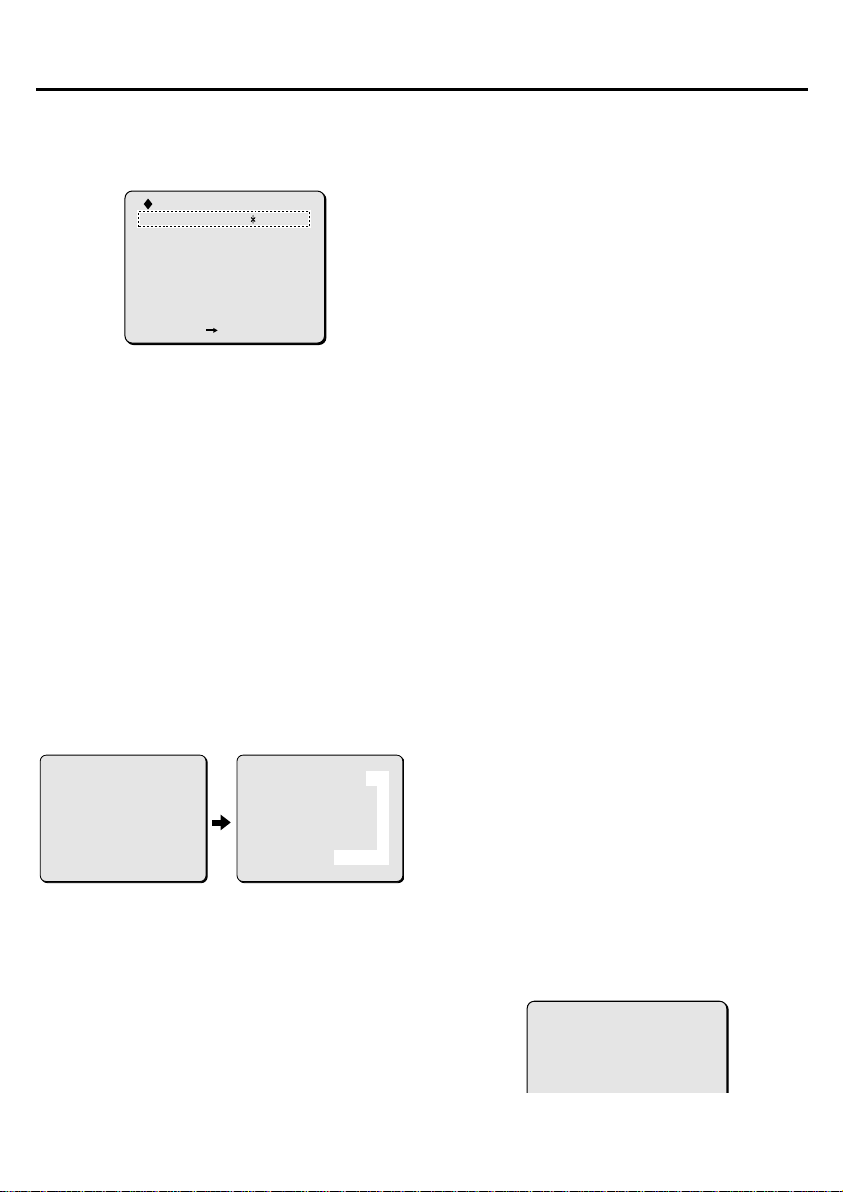
HARD DISK CAPACITY SETTINGS (HDD SET)
Hard disk initialization settings are shown in Figure 1. This section explains how to change the hard disk
recording capacity and how to initialize the hard disk.
Hard disk initialization
If the hard disk is initialized, all data which has been
recorded on the hard disk up to that point will be
erased. When initializing the hard disk, always be
sure to transfer any recorded image data to a
computer before doing the initialization.
Hard disk initialization requires a password to be
entered before the initialization is carried out, in
order to protect the image data. See page 32 for
details on setting the password.
Press the MENU button to return to the SETTING
screen.
1 Use the CURSOR (j or l) button to select
“SETTINGS” and then press the SET
button.
The SETTINGS screen will be displayed.
2 Use the CURSOR (j or l) button to select
“HDD SET” and then press the SET button.
The HDD SET screen will be displayed.
3 Use the CURSOR (j or l) button to select
“INITIALIZE” and then press the SET
button.
The INITIALIZE screen will be displayed, and
you will be prompted to enter the password.
(HDD SET)
<SUSPICION SHOTS: 7509PCS>
<ALARM TIME 45MIN>
<PRE ALARM 15MIN>
<POST ALARM 30MIN>
SPACE SET
INITIALIZE
[MENU] (SETTINGS)
(Fig. 1)
4 Use the CURSOR button and the SET
button to select the password characters
from the character palette.
“ö” characters will appear in the password
entry box.
(INITIALIZE)
PASSWORD :*
Charactor
palette
ABCDEFGHIJKLM
NOPQRSTUVWXYZ
0123456789
BS END
5 Use the CURSOR (j or l) button to select
“END” and then press the SET button.
The HDD INITIALIZE screen will be displayed.
6 Use the CURSOR button to set the capacity
of the alarm recording area.
Example:
1 Set the PRE ALARM item to 45 minutes.
2 Set the POST ALARM item to 20 minutes.
The “SUSPICION SHOTS” and “ALARM
TIME” settings will be made automatically.
7 Use the CURSOR (j or l) button to select
“INITIALIZE” and then use the CURSOR (d
or c) button to select “YES” and then
press the SET button.
The hard disk will be initialized, and the display
will then return to the SETTINGS screen.
If you select “NO”, the display will return to
the HDD SET screen.
(HDD INITIALIZE)
<SUSPICION SHOTS: 6834PCS>
<ALARM TIME 45MIN>
PRE ALARM 15 MIN
POST ALARM 30 MIN
INITIALIZE YES
(HDD INITIALIZE)
<SUSPICION SHOTS: 6834PCS>
<ALARM TIME 65MIN>
PRE ALARM 45 MIN
POST ALARM 20 MIN
INITIALIZE YES
DO NOT POWER OFF!
INITIALIZING NOW!
24 English
HARD DISK CAPACITY SETTINGS (HDD SET)
Changing the alarm capacity
After the hard disk has been initialized and when
no post-alarm images have yet been recorded in
the pre-alarm recording area of the hard disk,
“SPACE SET” will be displayed on the screen.
If “SPACE SET” is displayed on the screen, you can
then change the alarm capacity. If images have
been recorded in the post-alarm recording area,
then the alarm capacity cannot be changed. Delete
the alarm images or initialize the hard disk before
changing the alarm recording area capacity.
1 Use the CURSOR (j or l) button to
select “SETTINGS” and then press the SET
button.
The SETTINGS screen will be displayed.
2 Use the CURSOR (j or l) button to
select “HDD SET” and then press the SET
button.
The HDD SET screen will be displayed.
3 Use the CURSOR (j or l) button to
select “SPACE SET” and then press the SET
button.
The SPACE SET screen will be displayed.
5 Use the CURSOR (j or l) button to
select “SETUP” and then use the CURSOR
(d or c) button to select “YES” and then
press the SET button.
The capacity of the alarm recording area will
be changed, and the SPACE SET screen will be
displayed.
If you select “NO”, the display will return to
the HDD SET screen.
(SPACE SET)
<SUSPICION SHOTS: 3456PCS>
<ALARM TIME 70MIN>
PRE ALARM 30 MIN
POST ALARM 40 MIN
SETUP YES
(SPACE SET)
<SUSPICION SHOTS: 3456PCS>
<ALARM TIME 70MIN>
PRE ALARM 30 MIN
POST ALARM 40 MIN
SETUP YES
DO NOT POWER OFF!
SETTING NOW!
4 Use the CURSOR button to reset the
capacity of the alarm recording area.
Example:
1 Set the PRE ALARM item to 30 minutes.
2 Set the POST ALARM item to 40 minutes.
The “SUSPICION SHOTS” and “ALARM
TIME” settings will be made automatically.
Note: If some images have already been recorded
in the suspicion recording area, the setting
time for the alarm recording capacity will
change.
(HDD SET)
<SUSPICION SHOTS:
<ALARM TIME 45MIN>
<PRE ALARM 15MIN>
<POST ALARM 30MIN>
SPACE SET
INITIALIZE
[MENU] (SETTINGS)
6834
PCS>
English 25
(SPACE SET)
<SUSPICION SHOTS: 3456PCS>
<ALARM TIME 70MIN>
PRE ALARM 30 MIN
POST ALARM 40 MIN
SETUP NO
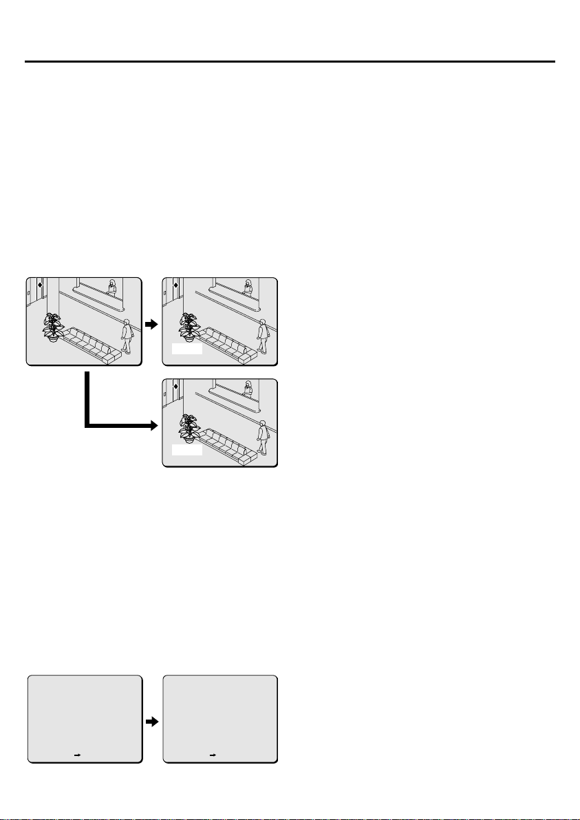
SUMMER TIME SETTINGS
(SUMMER TIME/DAYLIGHT SET)
Summer time settings include the time when summer time is to start and when it is to end. When summer
time has been set, the setting time will change automatically between standard time and summer time.
When image that have been recorded while summer time is active are being played back, a “ö” will appear
in front of the time display.
(Start time setting)
4 Use the CURSOR (l) button to select
“START”.
PAUSE PAUSE
PAUSE
2001/02/14 15:42:36 2001/02/14 15:42:36
2001/02/14 15:42:36
Setting example: Start time: 2 p.m. on the last
Sunday in March
End time: 2 p.m. on the 4th
Sunday in October
1 Use the CURSOR (l) button to select
“SETTINGS” and then press the SET button.
The SETTINGS screen will be displayed.
2 Use the CURSOR (j or l) button to select
“SUMMER TIME/DAYLIGHT SET” and then
press the SET button.
The SUMMER TIME/DAYLIGHT SET screen will
be displayed.
(SUMMER TIME/DAYLIGHT SET)
MODE ---------------- OFF
(START) (END)
WEEK 1ST LAST
SUN SUN
MONTH 04 10
HOUR 02 02
MINUTE 00 00
3 Use the CURSOR (d or c) button to set
“MODE ... ON”.
The “START” setting will be displayed.
(SUMMER TIME/DAYLIGHT SET)
MODE ---------------- ON
(START) (END) START
WEEK 1ST LAST 1ST
SUN SUN SUN
MONTH 04 10 04
HOUR 02 02 02
MINUTE 00 00 00
5 Use the CURSOR (l) button to select
“WEEK 1ST”, and then use the CURSOR (d
or c) button to select “LAST”.
Display: 1ST, 2ND, 3RD, 4TH, LAST
6 Use the CURSOR (l) button to select
“WEEK SUN”.
Display: SUN, MON, TUE, WED, THU, FRI, SAT
7 Use the CURSOR (l) button to select
“MONTH 04” and then use the CURSOR
(d or c) button to set the month to “03”.
Display: 1, 2, 3 ... 12
8 Use the CURSOR (l) button to select
“HOUR 02” and then use the CURSOR (d
or c) button to set the hour to “14”.
Display: 00, 01, 02, 03 ... 22, 23
9 Use the CURSOR (l) button to select
“MINUTE 00”.
Display: 00, 01, 02, 03 ... 58, 59
(SUMMER TIME/DAYLIGHT SET)
MODE ---------------- ON
(START) (END) START
WEEK LAST LAST LAST
SUN SUN SUN
MONTH 03 10 03
HOUR 14 02 14
MINUTE 00 00 00
26 English

SUMMER TIME SETTINGS
(SUMMER TIME/DAYLIGHT SET)
(End time setting)
10 Use the CURSOR (j or l) button to
select “START”, and then use the CURSOR
(d or c) button to select “END”.
11 Use the CURSOR (l) button to select
“WEEK LAST”, and then use the CURSOR
(d or c) button to select “4TH”.
12 Use the CURSOR (l) button to select
“WEEK SUN”.
13 Use the CURSOR (l) button to select
“MONTH 10”.
14 Use the CURSOR (l) button to select
“HOUR 02” and then use the CURSOR (d
or c) button to set the hour to “14”.
15 Use the CURSOR (l) button to select
“MINUTE 00”.
16 When all settings have been completed,
press the MENU button to return to the
SETTINGS screen.
Keep pressing the MENU button to return to
the MAIN MENU screen.
(SUMMER TIME/DAYLIGHT SET)
MODE ---------------- ON
(START) (END) END
WEEK 1ST LAST LAST
SUN SUN SUN
MONTH 04 10 10
HOUR 02 02 02
MINUTE 00 00 00
(SUMMER TIME/DAYLIGHT SET)
MODE ---------------- ON
(START) (END) END
WEEK LAST LAST 4TH
SUN SUN SUN
MONTH 03 10 10
HOUR 14 14 14
MINUTE 00 00 00
☞ Notes on summer time settings
When changing the current time setting using the
CLOCK SET screen, you cannot change it to a time
which is within one hour after the time when
summer time has been set to start. If you try to set
the time in this way, the time displayed will be
changed automatically to a setting which is one
hour after the time that you have actually set.
Furthermore, if you change the current time to a
time which is at least one hour before the time
when summer time has been set to end, the time
will be displayed exactly as you have set it.
For example: If summer time has been set to start
at 2.00 and you change the current time setting to
2.30 (the time becomes 3.30), then time settings
between 2.00 and 2.59 will be carried out
automatically.
For example: If summer time has been set to end
at 2.00 and you change the current time setting to
1.30 (the time becomes 1.30), then in this case you
cannot set the time to between 1.00 and 1.59.
(SUMMER TIME/DAYLIGHT SET)
MODE ---------------- ON
(START) (END) START
WEEK 1ST LAST FAST
SUN SUN SUN
MONTH 04 10 04
HOUR 02 02 02
MINUTE 00 00 00
(CLOCK SET)
YEAR------------------2002
MONTH----------------- 08
DAY------------------- 02
HOUR------------------ 02
MINUTE---------------- 30
SECOND---------------- 00
FORM------------MM/DD/YYYY
CLOCK START----------- YES
(CLOCK START)
2002/08/02 *3:30:00
[MENU] (SETTING)
Note: If the start time (START) and end time
(END) settings are the same, the time will
not change between standard time and
summer time, and the ST/DL setting in the
CONDITION will be set to “OFF”.
English 27

KEY WORD SETTING (KEY WORD SET)
These settings are useful for identifying image data when transferring it to a computer. In addition, the key
word setting status and the settings for the alarm recording area on the hard disk can be confirmed at the
CONDITION screen. You can also set passwords to protect important image data.
(KEY WORD SET)
1
2
3
FILE ID :A
CAMERA ID:
COMMENT :
4
5
CHANGE PASSWORD (DELETE)
CHANGE PASSWORD (INITIAL)
1 FILE ID: The file ID is initially set to “A”. You
can set a single character to appear at the front
of the file when transferring images which have
been recorded by this camera to a computer.
2 CAMERA ID: When this camera is one of
several cameras being used, up to five
characters can be specified as the identifying
name for the camera. This is useful for
identifying image data.
3 COMMENT: When this camera is one of several
cameras being used, you can enter a comment
of up to 36 characters to describe the setting-up
location for the camera.
4 CHANGE PASSWORD (DELETE): If necessary,
you can set a password which must be entered
in order to delete files. This password can be up
to eight characters long.
5 CHANGE PASSWORD (INITIAL): You can set a
password which must be entered in order to
initialize the hard disk. This password can be up
to eight characters long. When the hard disk is
initialized, all data on the hard disk is deleted, so
it is highly recommended that this password be
set by the camera operator.
☞ About passwords
When using the camera for the first time, you can
use the CURSOR button to select “END” from the
character palette and then press the SET button to
continue editing and deleting images without
having to set a password. You only have to set a
password if you think that a password might be
needed.
28 English

KEY WORD SETTING (KEY WORD SET)
Entering a file ID (1 character)
Example: To enter “P” as the file ID
1 Use the CURSOR (j or l) button to
select “SETTINGS” and then press the SET
button.
The SETTINGS screen will be displayed.
2 Use the CURSOR (j or l) button to
select “KEY WORD SET” and then press
the SET button.
The KEY WORD SET screen will be displayed.
(KEY WORD SET)
FILE ID :A
CAMERA ID:
SET
COMMENT :
CHANGE PASSWORD (DELETE)
CHANGE PASSWORD (INITIAL)
3 Use the CURSOR (l) button to select
“FILE ID” and then press the SET button.
You can then set the file ID in the KEY WORD
SET screen.
(KEY WORD SET)
FILE ID :A
SET
ABCDEFGHIJKLM
NOPQRSTUVWXYZ
0123456789
BS END
4 Use the CURSOR button to select the letter
“P” from the character palette and then
press the SET button.
When the character has been set, the cursor
will move automatically to “END”.
(KEY WORD SET)
SET
FILE ID :P
ABCDEFGHIJKLM
NOPQRSTUVWXYZ
0123456789
BS END
5 Press the SET button.
The display will return to the KEY WORD SET
screen.
6 When all settings have been completed,
press the MENU button to return to the
KEY WORD SET screen.
Keep pressing the MENU button to return to
the MAIN MENU screen.
English 29

Setting a camera ID (5 characters)
Example: To set the camera ID to “HALL1”
1 Use the CURSOR (l or j) button to select
“SETTINGS” and then press the SET
button.
The SETTINGS screen will be displayed.
2 Use the CURSOR (j or l) button to select
“KEY WORD SET” and then press the SET
button.
The KEY WORD SET screen will be displayed.
3 Use the CURSOR (l) button to select
“CAMERA ID” and then press the SET
button.
You can then set the camera ID in the KEY
WORD SET screen.
(KEY WORD SET)
FILE ID :P
CAMERA ID:
SET
COMMENT :
CHANGE PASSWORD (DELETE)
CHANGE PASSWORD (INITIAL)
(KEY WORD SET)
CAMERA ID:
5 Press the SET button.
The display will return to the KEY WORD SET
screen.
6 When all settings have been completed,
press the MENU button to return to the
SETTINGS screen.
Keep pressing the MENU button to return to
the MAIN MENU screen.
ABCDEFGHIJKLM
NOPQRSTUVWXYZ
0123456789.,
/-$&#'”()
END
4 Use the CURSOR button to select the
characters “H” in order from the character
palette, and the press the SET button.
Enter “ALL1” in same way.
When five characters have been selected, the
cursor will move automatically to “END”.
SET
(KEY WORD SET)
CAMERA ID:HALL1
30 English

KEY WORD SETTING (KEY WORD SET)
Entering a comments (up to 36 characters)
Example: Entering “SANYO DIGITAL RECORDING CAMERA” as a comment
1 Use the CURSOR (l or j) button to
select “SETTINGS” and then press the SET
button.
The SETTINGS screen will be displayed.
2 Use the CURSOR (j or l) button to
select “KEY WORD SET” and then press
the SET button.
The KEY WORD SET screen will be displayed.
3 Use the CURSOR (l) button to select
“COMMENT” and then press the SET
button.
You can then set the comment in the KEY
WORD SET screen.
(KEY WORD SET)
FILE ID :P
CAMERA ID:HALL1
SET
COMMENT :
CHANGE PASSWORD (DELETE)
CHANGE PASSWORD (INITIAL)
4 Use the CURSOR button and the SET
button to select “SANYO DIGITAL
RECORDING CAMERA” from the character
palette.
1 Use the CURSOR button to select “S” and
then press the SET button.
Enter “ANYO” in the same way.
2 Use the CURSOR button to select the
blank character below the letter “N” and
then press the SET button.
A space will be inserted after “SANYO”.
Enter “DIGITAL RECORDING CAMERA”
in the same way. Enter spaces in the first
line in order to move to the second line.
3 Use the CURSOR button to select “END”
and then press the SET button.
The display will return to the KEY WORD
SET screen.
(KEY WORD SET)
COMMENT :S
ABCDEFGHIJKLM
NOPQRSTUVWXYZ
0123456789.,
/-$&#'”()
END
SET
(KEY WORD SET)
COMMENT :SANYO
ABCDEFGHIJKLM
NOPQRSTUVWXYZ
0123456789.,
/-$&#'”()
(KEY WORD SET)
COMMENT :SANYO DIGITAL
RECORDING CAMERA
ABCDEFGHIJKLM
NOPQRSTUVWXYZ
0123456789.,
/-$&#'”()
END
END
English 31
5 When all settings have been completed,
press the MENU button to return to the
KEY WORD SET (for after setting) screen.
Keep pressing the MENU button to return to
the MAIN MENU screen.

Entering a password for deleting files (CHANGE PASSWORD
(DELETE))
This password is used when “DELETE” is selected from the FUNCTIONS screen during image playback
(ALARM, SUSPICION, ARCHIVE and EXTENSION).
The passwords are not set in the initial settings.
Example: Set the password to “CAMERA”.
1 Use the CURSOR (l or j) button to select
“SETTINGS” and then press the SET button.
The SETTINGS screen will be displayed.
2 Use the CURSOR (j or l) button to select
“KEY WORD SET” and then press the SET
button.
The KEY WORD SET screen will be displayed.
3 Use the CURSOR (l) button to select
“CHANGE PASSWORD (DELETE)” and then
press the SET button.
The cursor will move to the “OLD PASSWORD”
box in the CHANGE PASSWORD-DELETE screen.
(KEY WORD SET)
FILE ID :P
CAMERA ID:HALL1
COMMENT :SANYO DIGITAL
RECORDING CAMERA
CHANGE PASSWORD (DELETE)
CHANGE PASSWORD (INITIAL)
(CHANGE PASSWORD-DELETE)
OLD PASSWORD:
NEW PASSWORD:
VERIFICATION:
ABCDEFGHIJKLM
NOPQRSTUVWXYZ
0123456789
BS END
SET
4 Use the CURSOR (l) button to select
“END” and then press the SET button.
The initial setting “END” will be cleared and
the cursor will move to the “NEW
PASSWORD” box.
(CHANGE PASSWORD-DELETE)
OLD PASSWORD:
NEW PASSWORD:
VERIFICATION:
ABCDEFGHIJKLM
NOPQRSTUVWXYZ
0123456789
BS END
(CHANGE PASSWORD-DELETE)
OLD PASSWORD:
NEW PASSWORD:
VERIFICATION:
ABCDEFGHIJKLM
NOPQRSTUVWXYZ
0123456789
BS END
SET
5 Use the CURSOR button to select “C” and
then press the SET button.
The selected letter will appear as “ö”. Enter
“AMERA” in the same way.
(CHANGE PASSWORD-DELETE)
OLD PASSWORD:
NEW PASSWORD:*
VERIFICATION:
ABCDEFGHIJKLM
NOPQRSTUVWXYZ
0123456789
BS END
(CHANGE PASSWORD-DELETE)
OLD PASSWORD:
NEW PASSWORD:******
VERIFICATION:
ABCDEFGHIJKLM
NOPQRSTUVWXYZ
0123456789
BS END
SET
32 English

KEY WORD SETTING (KEY WORD SET)
6 Use the CURSOR (l) button to select
“END” and then press the SET button.
The password (CAMERA) will appear as
“цццццц” and the cursor will move to the
“VERIFICATION” box.
This prompts you to verify that the password
you have entered is correct.
(CHANGE PASSWORD-DELETE)
OLD PASSWORD:
NEW PASSWORD:******
SET
VERIFICATION:
ABCDEFGHIJKLM
NOPQRSTUVWXYZ
0123456789
BS END
7 Use the CURSOR button and the SET
button to enter “CAMERA” once more,
and then select “END” and press the SET
button.
The display will return to the KEY WORD SET
screen and the password for deleting images
will be set to “CAMERA”.
(CHANGE PASSWORD-DELETE)
OLD PASSWORD:
NEW PASSWORD:******
SET
VERIFICATION:******
ABCDEFGHIJKLM
NOPQRSTUVWXYZ
0123456789
BS END
8 When all settings have been completed,
press the MENU button to return to the
SETTINGS screen.
Keep pressing the MENU button to return to
the MAIN MENU screen.
English 33

Setting a password for initializing the hard disk
(CHANGE PASSWORD (INITIAL))
This password is used when “INITIALIZE” is selected from the HDD SET screen.
Example: To change the initial setting of “END” to “CMR”
1 Use the CURSOR (l or j) button to select
“SETTINGS” and then press the SET button.
The SETTINGS screen will be displayed.
2 Use the CURSOR (j or l) button to select
“KEY WORD SET” and then press the SET
button.
The KEY WORD SET screen will be displayed.
3 Use the CURSOR (l) button to select
“CHANGE PASSWORD (INITIAL)” and then
press the SET button.
The cursor will move to the “OLD
PASSWORD” box in the CHANGE
PASSWORD-INITIALIZE screen.
(KEY WORD SET)
FILE ID :P
CAMERA ID:HALL1
COMMENT :SANYO DIGITAL
RECORDING CAMERA
CHANGE PASSWORD (DELETE)
CHANGE PASSWORD (INITIAL)
(CHANGE PASSWORD-INITIALIZE)
OLD PASSWORD:
NEW PASSWORD:
VERIFICATION:
ABCDEFGHIJKLM
NOPQRSTUVWXYZ
0123456789
BS END
SET
4 Use the CURSOR (l) button to select
“END” and then press the SET button.
The initial setting “END” will be cleared and
the cursor will move to the “NEW
PASSWORD” box.
(CHANGE PASSWORD-INITIALIZE)
OLD PASSWORD:
NEW PASSWORD:
VERIFICATION:
ABCDEFGHIJKLM
NOPQRSTUVWXYZ
0123456789
BS END
(CHANGE PASSWORD-INITIALIZE)
OLD PASSWORD:
NEW PASSWORD:
VERIFICATION:
ABCDEFGHIJKLM
NOPQRSTUVWXYZ
0123456789
BS END
SET
5 Use the CURSOR button to select “C” and
then press the SET button.
The selected letter will appear as “ö”. Enter
“MR” in the same way.
(CHANGE PASSWORD-INITIALIZE)
OLD PASSWORD:
NEW PASSWORD:*
VERIFICATION:
ABCDEFGHIJKLM
NOPQRSTUVWXYZ
0123456789
BS END
(CHANGE PASSWORD-INITIALIZE)
OLD PASSWORD:
NEW PASSWORD:***
VERIFICATION:
ABCDEFGHIJKLM
NOPQRSTUVWXYZ
0123456789
BS END
SET
34 English

KEY WORD SETTING (KEY WORD SET)
6 Use the CURSOR (l) button to select
“END” and then press the SET button.
The password (CMR) will appear as “ööö”
and the cursor will move to the
“VERIFICATION” box.
This prompts you to verify that the password
you have entered is correct.
(CHANGE PASSWORD-INITIALIZE)
OLD PASSWORD:
NEW PASSWORD:***
SET
VERIFICATION:
ABCDEFGHIJKLM
NOPQRSTUVWXYZ
0123456789
BS END
7 Use the CURSOR button and the SET
button to enter “CMR” once more, and
then select “END” and press the SET
button.
The display will return to the KEY WORD SET
screen and the password for initializing the
hard disk will be set to “CMR”.
(CHANGE PASSWORD-INITIALIZE)
OLD PASSWORD:
NEW PASSWORD:***
SET
VERIFICATION:***
ABCDEFGHIJKLM
NOPQRSTUVWXYZ
0123456789
BS END
8 When all settings have been completed,
press the MENU button to return to the
SETTINGS screen.
Keep pressing the MENU button to return to
the MAIN MENU screen.
English 35

Correcting characters
The following two character palettes are used:
☞ For CAMERA ID and COMMENT settings
(KEY WORD SET)
CAMERA ID:HALL1
ABCDEFGHIJKLM
NOPQRSTUVWXYZ
0123456789.,
/-$&#'”()
☞ For PASSWORD or CAMERA ID setting
(CHANGE PASSWORD-DELETE)
OLD PASSWORD:
NEW PASSWORD:
VERIFICATION:
ABCDEFGHIJKLM
NOPQRSTUVWXYZ
0123456789
BS END
END
Example: If DIGITAL has been entered as
DIHITAL (using COMMENT palettes)
1 Use the CURSOR button to select 4 (or
3) from the character palette.
(KEY WORD SET)
COMMENT :SANYO DIHITAL
RECORDING CAMERA
ABCDEFGHIJKLM
NOPQRSTUVWXYZ
0123456789.,
/-$&#’”()
END
2 Keep pressing the SET button to select “H”.
The correction cursor (b) will move to “H”.
(KEY WORD SET)
COMMENT :SANYO DIGITAL
RECORDING CAMERA
ABCDEFGHIJKLM
NOPQRSTUVWXYZ
0123456789.,
/-$&#’”()
END
3 Use the CURSOR button to select “G” from
the character palette and then press the
SET button.
(KEY WORD SET)
COMMENT :SANYO DIGITAL
RECORDING CAMERA
ABCDEFGHIJKLM
NOPQRSTUVWXYZ
0123456789.,
/-$&#’”()
END
4 Use the CURSOR button to select “END”
from the character palette and then press
the SET button.
When inserting spaces between characters, move
the cursor to the blank character below the letter
“N” and then press the SET button.
36 English

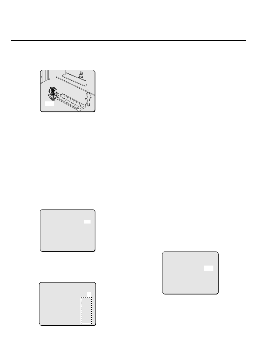
CHECKING THE CAMERA SETTING STATUS
The principal settings can be viewed on-screen. To check the settings, use the CURSOR (j or l) button to
select “CONDITION” from the MAIN MENU screen and then press the SET button.
Press the MENU button to return to the MAIN MENU screen.
•
(MAIN MENU)
RECORD START
PLAYBACK
SETTINGS
CONDITION
1 Checking the CLOCK SET settings
This shows the current time that has been set.
A “ö” in front of the time indicates that it is
summer time.
2 Checking the HDD SET settings
This shows the recording time for the alarm
recording area, and also shows the remaining
number of images that can be recorded.
PRE: Shows the number of minutes of
•
recording time for the pre-alarm
recording area
POST: Shows the number of minutes of
•
•
recording time for the post-alarm
recording area
SUSPICION: Shows the recording number
of images that can be recorded
(left) in the suspicion recording
area and the total recording
number set (right)
3 Checking the SYSTEM SET settings
FRAMERATE: Shows the frame rate for
suspicion recording
1 FPS: 1 still image recording per second
•
3 FPS: 3 still images recording per second
•
4 Checking the SUMMER TIME/DAYLIGHT SET
settings
ON: Summer time is currently being used
OFF: Summer time is not currently being used.
CONDITION CONDITION
CONDITION
TIME: 2002/08/02 15:15:20 TIME: 2002/08/02 15:15:20
TIME: 2002/08/02 15:15:20
1
PRE: 15MIN POST: 30MIN PRE: 15MIN POST: 30MIN
PRE: 15MIN POST: 30MIN
2
SUSPICION: 150/ 6834PCS SUSPICION: 150/ 6834PCS
SUSPICION: 150/ 6834PCS
FRAMERATE: 3FPS ST/DL:OFF FRAMERATE: 3FPS ST/DL:OFF
FRAMERATE: 3FPS ST/DL:OFF
3
FILE ID: A ID: FILE ID: A ID:
FILE ID: A ID:
5
COMMENT: COMMENT:
COMMENT:
[MENU] (MAIN MENU) [MENU] (MAIN MENU)
[MENU] (MAIN MENU)
5 Checking the KEY WORD SET settings
FILE ID: Shows the file ID that has been set
•
CAMERA ID: Shows the camera ID that has
•
COMMENT: Shows the comment which has
•
been set
been set
4
English 37

SETTING THE RECORDING METHOD
Note:
Illumination
•
The shutter speed for this camera is set
automatically in accordance with the brightness of
the object being recorded. If the object being
recorded is moving and the resulting images are
out of focus, increase the amount of illumination.
Image quality
•
The images on the monitor screen comply with a
digital image format (VGA equivalent: 640 x 480
dots), so the resolution will appear less sharp than
images which are displayed on a computer screen.

SETTING THE RECORDING METHOD
Before using this camera, make sure that you set the current date and time. Recording will not be
possible if they have not been set. (See page 22)
The images which are recorded by this camera (three images per second) are saved onto the hard disk. The initial
settings for the hard disk are shown in the illustration, but each of the settings can be changed if required.
For details on changing the hard disk settings, refer to “HDD SET” in the SETTINGS screen. (See page 24)
(HDD SET) (HDD SET)
(HDD SET)
<SUSPICION SHOTS: 6834PCS> <SUSPICION SHOTS: 6834PCS>
<SUSPICION SHOTS: 6834PCS>
1
<ALARM TIME 45MIN> <ALARM TIME 45MIN>
<ALARM TIME 45MIN>
2
<PRE ALARM 15MIN> <PRE ALARM 15MIN>
<PRE ALARM 15MIN>
3
<POST ALARM 30MIN> <POST ALARM 30MIN>
<POST ALARM 30MIN>
4
SPACE SET SPACE SET
SPACE SET
5
INITIALIZE INITIALIZE
INITIALIZE
6
[MENU] (SETTINGS) [MENU] (SETTINGS)
[MENU] (SETTINGS)
1 Number of images that can be stored in the
suspicion recording area
2 Total recording time available in the alarm
recording area
3 Recording time available in the pre-alarm
recording area
4 Recording time available in the post-alarm
recording area
5 Used for changing the alarm time (automatic or
number of suspicion images)
6 Used for hard disk initialization
The two available methods of recording the
captured images are alarm recording and
suspicion recording.
If the H (HOLD-UP) switch at the rear of the camera is
not operated while recording images in the alarm
recording area, then once recording has continued for
the full length of time that has been set, it starts again
automatically from the beginning of the hard disk and
the images which are already on the hard disk are
overwritten. This operation is continually repeated until
recording is stopped.
For example, if new images are recorded at the
beginning of the hard disk over the top of old images,
then once 2 minutes and 30 seconds of new images
have been recorded, 5 minutes’ worth of old images
will be deleted automatically.
Alarm recording
Alarm recording can be divided into pre-alarm
recording, post-alarm recording and backup recording.
For each method, images are recorded in the alarm
recording area of the hard disk. The recording time
can be set to between 10 and 90 minutes.
☞ Pre-alarm (PRE1) recording
This is the normal method used for recording images.
When “RECORD START” is selected, pre-alarm
recording starts automatically. Images are recorded in
the pre-alarm (PRE1) recording area of the hard disk.
For example, if the ALARM TIME recording period is
set to the initial setting of 45 minutes, continuous
recording to the pre-alarm area for 45 minutes occurs
if no post-alarm recording is carried out. However, if
the H (HOLD-UP) switch at the rear of the camera is
turned on, the images recorded during the first 30
minutes of the 45-minute pre-alarm recording period
are deleted, and this space then becomes the
post-alarm recording area (POST ALARM 30 min) and
is used for post-alarm recording. The pre-alarm
recording area (PRE ALARM 15 MIN) is maintained
according to the settings.
☞ Post-alarm (POST-1) recording
A switch must be connected to the H (HOLD-UP)
terminal at the rear of the camera for post-alarm
recording to be carried out. Post-alarm recording is
then carried out while the hold-up (H) switch is turned
on.
If the switch which is connected to the H terminal is
pressed and held during pre-alarm recording, the
recording mode changes from pre-alarm recording to
post-alarm recording. The images are recorded in the
post-alarm (POST1) recording area of the hard disk.
English 39

☞ Backup recording
If there is 20 minutes or more of available recording
time remaining in the post-alarm recording area of
the hard disk after post-alarm (POST1) recording is
completed, pre-alarm 2 (PRE2) recording [which is
distinct from pre-alarm (PRE1) recording] starts
automatically. If the hold-up (H) switch is then
pressed, post-alarm 2 (POST2) recording [which is
distinct from post-alarm (POST1) recording] starts.
The recording time for backup recording is set
automatically according to the ratio between the
pre-alarm 2 (PRE2) and the post-alarm 2 (POST2)
recording times.
Note:
If any of the following occur, “ALARM REC FULL”
will be displayed on the screen and recording in the
alarm recording area will no longer be possible.
At such times, transfer the image data to a
computer and clear the images from the alarm
recording area, or re-initialize the hard disk.
If the pre-alarm and post-alarm recording areas
•
become full
When post-alarm 2 (POST2) recording is
•
complete, because this is the final recording
area used
If the available recording time for alarm
•
recording is reduced to 20 minutes or less.
Suspicion recording
This recording method is used at times such as
when a suspicious individual is noticed. A switch
must be connected to the S (SUSPICION) terminal
at the rear of the camera for suspicion recording to
be carried out. If the switch which is connected to
the S terminal is pressed during pre-alarm
recording, the recording mode changes from
pre-alarm recording to suspicion recording. The
images are recorded in the suspicion recording area
of the hard disk. The number of images that can be
recorded is set automatically to between 11,565
and 502 images, depending on the alarm recording
time setting.
40 English

SETTING THE RECORDING METHOD
Pre-alarm recording flow
1
Images at 10:00:00 Images at 10:05:00
PRE1-ALARM REC
PRE1-ALARM REC PRE1-ALARM REC
REMAIN SHOTS:6834 REMAIN SHOTS:6834
REMAIN SHOTS:6834
PRE1-ALARM REC PRE1-ALARM REC
PRE1-ALARM REC
REMAIN SHOTS:6834 REMAIN SHOTS:6834
REMAIN SHOTS:6834
2
Images at 10:20:00 Images at 10:21:00
POST1-ALARM REC POST1-ALARM REC
POST1-ALARM REC POST1-ALARM REC POST1-ALARM REC POST1-ALARM REC POST1-ALARM REC POST1-ALARM REC POST1-ALARM REC POST1-ALARM REC POST1-ALARM REC POST1-ALARM REC POST1-ALARM REC POST1-ALARM REC POST1-ALARM REC POST1-ALARM REC POST1-ALARM REC POST1-ALARM REC
Pre-alarm (PRE1) area recording in progress
PRE1-ALARM REC PRE1-ALARM REC
PRE1-ALARM REC
REMAIN SHOTS:6834 REMAIN SHOTS:6834
REMAIN SHOTS:6834
PRE1-ALARM REC PRE1-ALARM REC
PRE1-ALARM REC
REMAIN SHOTS:6834 REMAIN SHOTS:6834
REMAIN SHOTS:6834
PRE1-ALARM REC
PRE1-ALARM REC PRE1-ALARM REC
REMAIN SHOTS:6834 REMAIN SHOTS:6834
REMAIN SHOTS:6834
Post-alarm (POST1) area recording in progress
PRE1-ALARM REC
PRE1-ALARM REC PRE1-ALARM REC
REMAIN SHOTS:6834 REMAIN SHOTS:6834
REMAIN SHOTS:6834
REMAIN SHOTS:6834 REMAIN SHOTS:6834 REMAIN SHOTS:6834 REMAIN SHOTS:6834 REMAIN SHOTS:6834 REMAIN SHOTS:6834
Post-alarm (POST1) area recording in progress Post-alarm (POST2) area recording in progress
Images at 10:24:00
POST1-ALARM REC POST1-ALARM REC POST1-ALARM REC POST1-ALARM REC POST1-ALARM REC POST1-ALARM REC POST1-ALARM REC POST1-ALARM REC POST1-ALARM REC
REMAIN SHOTS:6834 REMAIN SHOTS:6834 REMAIN SHOTS:6834 REMAIN SHOTS:6834 REMAIN SHOTS:6834 REMAIN SHOTS:6834 REMAIN SHOTS:6834 REMAIN SHOTS:6834 REMAIN SHOTS:6834
5 6
Images at 10:27:00
POST2-ALARM REC
POST2-ALARM REC POST2-ALARM REC POST2-ALARM REC
POST2-ALARM REC
REMAIN SHOTS:6834 REMAIN SHOTS:6834 REMAIN SHOTS:6834
1 Pre-alarm (PRE1) recording starts from
10:00:00
Images are stored to the pre-alarm recording area.
2 An emergency situation develops at
10:20:00, and you want to record images
in the post-alarm area.
Post-alarm (POST1) recording starts when the
hold-up switch is pressed and held.
POST2-ALARM REC
POST2-ALARM REC
REMAIN SHOTS:6834 REMAIN SHOTS:6834 REMAIN SHOTS:6834 REMAIN SHOTS:6834 REMAIN SHOTS:6834 REMAIN SHOTS:6834
REMAIN SHOTS:6834 REMAIN SHOTS:6834 REMAIN SHOTS:6834 REMAIN SHOTS:6834 REMAIN SHOTS:6834 REMAIN SHOTS:6834 REMAIN SHOTS:6834 REMAIN SHOTS:6834 REMAIN SHOTS:6834 REMAIN SHOTS:6834 REMAIN SHOTS:6834 REMAIN SHOTS:6834
3
4
Images at 10:25:00
PRE2-ALARM REC PRE2-ALARM REC
REMAIN SHOTS:6834 REMAIN SHOTS:6834 REMAIN SHOTS:6834 REMAIN SHOTS:6834 REMAIN SHOTS:6834 REMAIN SHOTS:6834 REMAIN SHOTS:6834 REMAIN SHOTS:6834 REMAIN SHOTS:6834
PRE2-ALARM REC PRE2-ALARM REC PRE2-ALARM REC PRE2-ALARM REC PRE2-ALARM REC PRE2-ALARM REC PRE2-ALARM REC
Post-alarm (POST2) area recording in progress
Images at 10:28:00
POST2-ALARM REC
POST2-ALARM REC
POST2-ALARM REC
POST2-ALARM REC
POST2-ALARM REC
REMAIN SHOTS:6834 REMAIN SHOTS:6834 REMAIN SHOTS:6834
POST2-ALARM REC
POST2-ALARM REC
POST2-ALARM REC
POST2-ALARM REC
POST2-ALARM REC
REMAIN SHOTS:6834 REMAIN SHOTS:6834 REMAIN SHOTS:6834 REMAIN SHOTS:6834 REMAIN SHOTS:6834 REMAIN SHOTS:6834
POST2-ALARM REC
4 Backup recording starts.
If there is 20 minutes or more of available
recording time remaining in the alarm recording
area of the hard disk, pre-alarm (PRE2) recording
starts automatically at 10:25:00.
5 An emergency situation develops again at
10:27:00 and you want to record images in
the post-alarm2 area.
Post-alarm (POST2) recording starts when the alarm
3 Post-alarm recording is stopped at
10:25:00.
Post-alarm (POST1) recording stops when the
hold-up switch is released.
switch is pressed and held.
6 Post-alarm recording is stopped at
10:29:00.
When the hold-up switch is released, “ALARM REC
FULL” appears on the screen and recording stops.
English 41

Screen displays
1 Display during recording
During recording, the screen display will switch off
•
after 30 seconds have passed. You can make the
screen display re-appear by pressing the SET or
CURSOR button.
The screen display can be set to switch off immediately
•
from the start of recording. To do this, set “CAUTION
LED” on the SYSTEM SET screen to OFF. To re-display
the screen, set it back to ON. (See page 23)
2 Number of suspicion recording images
Pre-alarm recording
PRE1-ALARM REC
PRE1-ALARM REC
1
REMAIN SHOTS: 6834
REMAIN SHOTS: 6834
2
1 Press the MENU button.
The MAIN MENU screen will be displayed.
If the MAIN MENU screen remains displayed for about
30 seconds, pre-alarm recording will then start
automatically.
1 2
MENU
2 Use the CURSOR (j or l) button to select
“RECORD START” and then press the SET button.
“PRE1-ALARM REC” will be displayed and
pre-alarm (PRE1) recording will start.
The warning indicator and caution
indicator both light during pre-alarm
recording.
Note: Pre-alarm recording will continue with the images being recorded in the pre-alarm (PRE1) area of the
hard disk until the hold-up switch or suspicion switch at the back of the camera is pressed.
SET
SETMENU
(MAIN MENU)
RECORD START
PLAYBACK
SETTINGS
CONDITION
PRE1-ALARM REC
PRE1-ALARM REC
REMAIN SHOTS: 6834
REMAIN SHOTS: 6834
NTSC
3 Press the MENU button to stop recording.
The display will return to the MAIN MENU screen.
PAL
42 English

SETTING THE RECORDING METHOD
Post-alarm recording
1 Press the MENU button.
The MAIN MENU screen will be displayed.
MENU
(MAIN MENU)
RECORD START
PLAYBACK
SETTINGS
CONDITION
2 Use the CURSOR (j or l) button to select
“RECORD START” and then press the SET button.
The warning indicator and caution
indicator both light during post-alarm
recording.
“PRE1-ALARM REC” will be displayed and
pre-alarm (PRE1) recording will then start.
3 Press and hold the H (HOLD-UP) switch (rear panel).
“POST1-ALARM REC” will be displayed and post-alarm
1 (POST1) recording will start.
Post-alarm recording will stop when the hold-up switch is
released, or when the post-alarm recording time which
was initially set has passed.
SET
PRE1-ALARM REC
PRE1-ALARM REC
REMAIN SHOTS: 6834
REMAIN SHOTS: 6834
POST1-ALARM REC POST1-ALARM REC
POST1-ALARM REC
REMAIN SHOTS: 6834 REMAIN SHOTS: 6834
REMAIN SHOTS: 6834
4 Release the H (HOLD-UP) switch to stop recording.
If there is 20 minutes or more of available recording time remaining in the post-alarm recording
•
area, pre-alarm 2 (PRE2) recording starts automatically.
When the recording area becomes full, “ALARM REC FULL” will be displayed and recording will no
•
longer be possible.
English 43

Backup recording
If there is 20 minutes or more of available recording time remaining in the post-alarm recording area of the
hard disk after post-alarm recording is completed, backup recording (pre-alarm 2 (PRE2) recording) starts
automatically. It follows from this that if there is not 20 minutes or more of time remaining, backup
recording is not carried out.
PRE2-ALARM REC PRE2-ALARM REC
PRE2-ALARM REC
1 Pre-alarm 2 (PRE2) recording starts automatically.
“PRE2-ALARM REC” is displayed.
REMAIN SHOTS: 6834 REMAIN SHOTS: 6834
REMAIN SHOTS: 6834
2 If an emergency situation develops, press and hold
the H (HOLD-UP) switch.
“POST2-ALARM REC” will be displayed and post-alarm
2 (POST2) recording will start.
POST2-ALARM REC POST2-ALARM REC
POST2-ALARM REC
REMAIN SHOTS: 6834 REMAIN SHOTS: 6834
REMAIN SHOTS: 6834
3 When the emergency situation has ended, release the H (HOLD-UP) switch.
“ALARM REC FULL” will be displayed and alarm recording will end.
Note:
When post-alarm 2 (POST2) recording has ended, there will not be any more space available for recording,
and so it will not be possible to continue alarm recording. To re-start pre-alarm recording, transfer the image
data to a computer and then carry out either one of the following two operations.
Select “DELETE” from the FUNCTIONS screen, and delete all of the image data. (See page 73)
•
Select “INITIALIZE” from the HDD SET sub-screen of the SETTINGS screen and re-initialize the hard disk.
•
(See page 24)
44 English

SETTING THE RECORDING METHOD
Suspicion recording flow
1
PRE1-ALARM REC
PRE1-ALARM REC PRE1-ALARM REC
Images at 10:00:00 Images at 10:05:00
PRE1-ALARM REC PRE1-ALARM REC
PRE1-ALARM REC
Pre-alarm (PRE1) area recording in progress
PRE1-ALARM REC PRE1-ALARM REC
PRE1-ALARM REC
PRE1-ALARM REC
PRE1-ALARM REC PRE1-ALARM REC
PRE1-ALARM REC
PRE1-ALARM REC PRE1-ALARM REC
PRE1-ALARM REC
PRE1-ALARM REC PRE1-ALARM REC
REMAIN SHOTS: 6834 REMAIN SHOTS: 6834
REMAIN SHOTS:6834
REMAIN SHOTS:6834 REMAIN SHOTS:6834
REMAIN SHOTS:6834
REMAIN SHOTS:6834 REMAIN SHOTS:6834
REMAIN SHOTS:6834
2
Images at 10:20:00 Images at 10:20:15
SUSPICION REC
SUSPICION REC SUSPICION REC
REMAIN SHOTS:6834 REMAIN SHOTS:6834
REMAIN SHOTS:6834
SUSPICION REC
SUSPICION REC SUSPICION REC
REMAIN SHOTS:6834 REMAIN SHOTS:6834
REMAIN SHOTS:6834
SUSPICION REC SUSPICION REC
SUSPICION REC
REMAIN SHOTS:6834 REMAIN SHOTS:6834
REMAIN SHOTS:6834
4
SUSPICION REC
SUSPICION REC SUSPICION REC
REMAIN SHOTS:6789 REMAIN SHOTS:6789
REMAIN SHOTS:6789
1 Pre-alarm (PRE1) recording starts from
10:00:00.
Images are recorded in the pre-alarm (PRE1)
recording area.
2 A suspicious person is discovered at
10:20:00 and you want to record images of
this person.
Press and hold the suspicion switch. Images will be
recorded in the suspicion recording area.
The image frame rate is three images per
•
second (default setting). The frame rate can also
be set to one image per second. (See page 23)
SUSPICION REC SUSPICION REC
SUSPICION REC
REMAIN SHOTS:6789 REMAIN SHOTS:6789
REMAIN SHOTS:6789
SUSPICION REC SUSPICION REC
SUSPICION REC
REMAIN SHOTS:6789 REMAIN SHOTS:6789
REMAIN SHOTS:6789
REMAIN SHOTS:6834 REMAIN SHOTS:6834
REMAIN SHOTS:6834
Pre-alarm (PRE1) area recording in progressSuspicion area recording in progress
3
PRE1-ALARM REC
PRE1-ALARM REC PRE1-ALARM REC
REMAIN SHOTS:6789 REMAIN SHOTS:6789
REMAIN SHOTS:6789
Pre-alarm (PRE1) area recording in progressSuspicion area recording in progress
5
REMAIN SHOTS:6834 REMAIN SHOTS:6834
REMAIN SHOTS:6834
PRE1-ALARM REC
PRE1-ALARM REC PRE1-ALARM REC
REMAIN SHOTS:6789 REMAIN SHOTS:6789
REMAIN SHOTS:6789
REMAIN SHOTS:6834 REMAIN SHOTS:6834
REMAIN SHOTS:6834
PRE1-ALARM REC PRE1-ALARM REC
PRE1-ALARM REC
REMAIN SHOTS:6789 REMAIN SHOTS:6789
REMAIN SHOTS:6789
Images at 10:40:05Images at 10:40:00
PRE2-ALARM REC
PRE2-ALARM REC PRE2-ALARM REC
REMAIN SHOTS:6764 REMAIN SHOTS:6764
REMAIN SHOTS:6764
PRE2-ALARM REC PRE2-ALARM REC
PRE2-ALARM REC
REMAIN SHOTS:6764 REMAIN SHOTS:6764
REMAIN SHOTS:6764
PRE2-ALARM REC PRE2-ALARM REC
PRE2-ALARM REC
REMAIN SHOTS:6764 REMAIN SHOTS:6764
REMAIN SHOTS:6764
4 A suspicious person is discovered again at
10:40:00 and you want to record images of
this person.
Press and hold the suspicion switch. Images will be
recorded in the suspicion recording area.
5 Suspicion recording is stopped at 10:40:05.
Suspicion recording stops when the suspicion
switch is released.
3 Suspicion recording is stopped at 10:20:15.
Suspicion recording stops when the suspicion
switch is released.
English 45

Suspicion recording
When the frame rate for suspicion recording is set to 1 FPS, one image is recorded per second; when it is set
to 3 FPS, three images are recorded per second. When the frame rate is set to 3 FPS, three images are
recorded for each single capture.
1 Press the MENU button.
The MAIN MENU screen will be displayed.
The image frame rate is three images per second
•
(default setting). The frame rate can also be set to
one image per second.
MENU
2 Use the CURSOR (j or l) button to
select “RECORD START” and then press
the SET button.
“PRE1-ALARM REC” will be displayed and
pre-alarm recording will start.
Note: If the frame rate is 1 FPS, a maximum of 15 minutes of recording is possible. If the frame rate is 3
FPS, a maximum of 5 minutes of recording is possible. If suspicion recording is still continuing when
these time limits are reached, suspicion recording will then stop and pre-alarm recording will resume.
SET
(MAIN MENU)
RECORD START
PLAYBACK
SETTINGS
CONDITION
PRE1-ALARM REC
PRE1-ALARM REC
REMAIN SHOTS: 6834
REMAIN SHOTS: 6834
3 Press and hold the S (SUSPICION) switch (rear panel).
“SUSPICION REC” will be displayed and suspicion recording will start.
The remaining number of images that can be recorded during suspicion recording becomes less each
time the S (SUSPICION) switch is pressed (recording is carried out).
SUSPICION REC SUSPICION REC
SUSPICION REC
PRE1-ALARM REC
PRE1-ALARM REC PRE1-ALARM REC
REMAIN SHOTS: 6834
REMAIN SHOTS: 6834 REMAIN SHOTS: 6834
4 Release the S (SUSPICION) switch to stop recording.
46 English
REMAIN SHOTS: 6833
REMAIN SHOTS: 6833 REMAIN SHOTS: 6833

SETTING THE RECORDING METHOD
Remaining number of shots for suspicion recording
The remaining number of images that can be recorded during suspicion recording appears in the
bottom-right corner of the screen during alarm recording and suspicion recording. The illustrations below
show the minimum number of remaining images under different initial setting conditions.
(3 images per second) (1 image per second)
(SYSTEM SET)
BLC CONTROL -------- OFF
CAUTION LED -------- ON
SUSPICION FRAMERATE 3 FPS
SUSPICION LOOP ----- OFF
FLICKER LESS ------- OFF
(SYSTEM SET)
BLC CONTROL -------- OFF
CAUTION LED -------- ON
SUSPICION FRAMERATE 1 FPS
SUSPICION LOOP ----- OFF
FLICKER LESS ------- OFF
[MENU] (SETTINGS)
(HDD SET)
<SUSPICION SHOTS: 6834PCS>
<ALARM TIME 45MIN>
<PRE ALARM 15MIN>
<POST ALARM 30MIN>
SPACE SET
INITIALIZE
[MENU] (SETTINGS)
PRE1-ALARM REC
PRE1-ALARM REC
REMAIN SHOTS: 6834
REMAIN SHOTS: 6834
☞ When the remaining number of images reaches zero
To delete images, select “DELETE” from the
•
FUNCTIONS screen during suspicion playback.
(See page 73)
To have old images overwritten with new
•
images automatically, set “SUSPICION LOOP”
in the SYSTEM SET screen to ON. (See page 23)
“LOOP” will then appear as the remaining
number of images during recording.
[MENU] (SETTINGS)
(HDD SET)
<SUSPICION SHOTS: 4556PCS>
<ALARM TIME 45MIN>
<PRE ALARM 15MIN>
<POST ALARM 30MIN>
SPACE SET
INITIALIZE
[MENU] (SETTINGS)
SUSPICION REC
SUSPICION REC
REMAIN SHOTS: 4556
REMAIN SHOTS: 4556
SUSPICION REC
SUSPICION REC
REMAIN SHOTS: LOOP REMAIN SHOTS: LOOP
REMAIN SHOTS: LOOP
English 47

PLAYING BACK AND SAVING
RECORDED IMAGES

PLAYING BACK AND SAVING RECORDED
IMAGES
This section describes the methods for playing back
the images which have been recorded, and saving
images of emergency situations and suspicious
individuals onto a hard disk or memory card. When
images which need to be kept are saved in the
archive recording area of the hard disk or onto a
memory card, the images which have been
recorded in the alarm recording area and suspicion
recording area are no longer needed.
Images in the alarm recording area and suspicion
recording area which are no longer needed should
be deleted to make space available for subsequent
recording in the various alarm recording areas.
Note:
When the hard disk is initialized, the images in
the archive recording area are also deleted.
To retain copies of these images, either save them
onto a memory card, or use the accessory “Digital
Recording Camera Utility Software” application
to transfer the images to a computer’s hard disk.
Saving images onto a memory card (See page 70)
•
Transferring images to a computer (See page 81)
•
Alarm playback
This is used to play back alarm recording images
which have been recorded onto the hard disk at the
rate of 3 FPS (three frames per second). Three
fast-forwarding and fast-rewinding intervals (5
seconds, 15 seconds and 30 seconds) are available
for skipping quickly through the captured images.
Suspicion playback
This is used to play back images which have been
recorded at the rate of 1 FPS or 3 FPS in the
suspicion recording area of the hard disk.
Archive playback
This is used to play back images which have been
saved in the alarm and suspicion recording areas.
You can then select “COPY” from the FUNCTIONS
screen during alarm or suspicion playback to copy
the images being played back. The copied images
are then saved in the archive recording area of the
hard disk, so that they can be viewed using archive
playback. A maximum of 500 images can be stored
in the archive recording area.
Extension playback
This is used to play back alarm and suspicion
images which have been saved onto a memory
card. A memory card is required in order to use
extension playback. After inserting the memory
card into the extension port, play back alarm and
suspicion images. Then select “COPY” from the
FUNCTIONS screen to copy the images being
played back onto the memory card. Images which
have been copied onto the memory card can then
be viewed using extension playback.
In addition, when using any of the above playback
methods, you can also use additional functions such
as image enlargement, date/time/information
display, image saving (except for archive and
extension playback) and image deleting.
English 49

Playback screen and image saving flow
MAIN MENU screen
(MAIN MENU)
RECORD START
PLAYBACK
SETTINGS
CONDITION
Alarm playback
(ALARM PLAYBACK)
<PRE1> <POST1>
PRE1
POST1
PRE2
POST2 <PRE2> <POST2>
NO IMAGE NO IMAGE
PRE1-PAUSE PRE1-PAUSE
PRE1-PAUSE
PLAY PLAY
PLAY
FUNCTION FUNCTION
FUNCTION
2001/02/14 15:25:50 1/3 2001/02/14 15:25:50 1/3
2001/02/14 15:25:50 1/3
(FUNCTIONS)
(FUNCTIONS)
ZOOM
ZOOM
ON SCREEN DISPLAY
ON SCREEN DISPLAY
COPY
COPY
DELETE
DELETE
2001/02/15 15:25:50 1/3 2001/02/15 15:25:50 1/3
2001/02/15 15:25:50 1/3
b Play back the recorded
images.
(PLAYBACK)
ALARM
SUSPICION
ARCHIVE
EXTENSION
[MENU] (MAIN MENU)
Suspicion playback
(SUSPICION PLAYBACK)
<DATE> <SUSPICION>
2001/02/05 000055
2001/02/17 000030
2001/02/19 000080
2001/02/20 000018
2001/02/25 000088
2001/03/01 000065
2001/03/03 000028
Archive playback
(ARCHIVE)
<2001>
<03/27>
13:24:56
13:45:26
14:02:38
14:23:59
*16:34:07
Extension playback
(EXTENS)
<2001>
<03/27>
13:24:56
13:45:26
14:02:38
14:23:59
*16:34:07
(SUSPIC.)
<2001>
<02/15>
13:24:56
13:45:26
14:02:38
14:23:59
16:34:07
17:51:43
ARCHIVE
ARCHIVE ARCHIVE
FUNCTION
FUNCTION FUNCTION
(S)2001/02/15 15:25:50 1/3
(S)2001/02/15 15:25:50 1/3 (S)2001/02/15 15:25:50 1/3
EXTENSION
EXTENSION EXTENSION
FUNCTION
FUNCTION FUNCTION
(A)2001/02/15 15:25:50 1/3 (A)2001/02/15 15:25:50 1/3
(A)2001/02/15 15:25:50 1/3
SUSPICION
SUSPICION SUSPICION
FUNCTION FUNCTION
FUNCTION
2001/02/15 15:25:50 1/3 2001/02/15 15:25:50 1/3
2001/02/15 15:25:50 1/3
(FUNCTIONS)
(FUNCTIONS)
ZOOM
ZOOM
ON SCREEN DISPLAY
ON SCREEN DISPLAY
DELETE
DELETE
(A)
2001/02/15 15:25:50 1/32001/02/15 15:25:50 1/3
2001/02/15 15:25:50 1/3
(A)
50 English

PLAYING BACK AND SAVING RECORDED IMAGES
ALARM Playback
Images which have been recorded on the hard disk using pre-alarm recording and post-alarm recording can
be played back.
1 Press the MENU button.
The MAIN MENU screen will be displayed.
2 Use the CURSOR (j or l) button to select
“PLAYBACK” and then press the SET button.
The PLAYBACK screen will be displayed.
3 Use the CURSOR (j or l) button to select
“ALARM” and then press the SET button.
The ALARM PLAYBACK screen will be
displayed and a 4-section split screen will
appear.
4 Use the CURSOR (j or l) button to select the next
alarm recording and then press the SET button.
The images in the selected recording area will be
displayed in a 9-section split screen.
PRE1: Images recorded in the pre-alarm recording
•
area of the hard disk
POST1: Images recorded in the post-alarm recording
•
area of the hard disk
PRE2, POST2: Pre-alarm 2 and post-alarm 2 images
•
which have been recorded automatically in the
post-alarm recording area of the hard disk
Note: If there is no recording history for one of the recording
areas of the hard disk, “NO IMAGE” is displayed. In
addition, if there is no recording history for a recording
area, that recording area cannot be selected.
MENU
SET
SET
(MAIN MENU)
RECORD START
PLAYBACK
SETTINGS
CONDITION
(MAIN MENU)
RECORD START
PLAYBACK
SETTINGS
CONDITION
(PLAYBACK)
ALARM
SUSPICION
ARCHIVE
EXTENSION
[MENU] (MAIN MENU)
(ALARM PLAYBACK)
<PRE1> <POST1>
PRE1
POST1
PRE2
POST2 <PRE2> <POST2>
NO IMAGE NO IMAGE
English 51

5 Use the CURSOR (j, l, d or c)
1 2 3
button to select the image to be played
back, and then press the SET button.
The selected image will be displayed as a
still image in the whole of the screen.
6 Use the CURSOR (d or c) button to select another
image before or after the first one.
Keep pressing this button to jog through the images in
order to locate the images to be played back. You can
also press and hold the CURSOR (d or c) button to
scroll the images in slow motion playback.
7 Use the CURSOR (j or l) button to select “PLAY”
and then press the SET button.
“PAUSE” will be displayed and the images
will be played back at the rate of 3 FPS
(three frames per second).
1 Date recorded
2 Time recorded
A “*” in front of the time indicates that it is showing
summer time.
3 Frame number indicator (three images per second:
1/3 → 2/3 → 3/3)
Clearing the screen display
•
If you do not need the screen display to appear during
playback, press the CURSOR (j or l) button to make
it disappear. Press once more to make the display
reappear.
Selecting “FUNCTION” screen functions
•
Use the CURSOR (j or l) button to select
“FUNCTION”. You can then enlarge images, display
date, time and other information, copy images and
delete images. (See page 65)
SET
PRE1-PAUSE
PRE1-PAUSE
PLAY
PLAY
FUNCTION
FUNCTION
2001/02/14 15:25:50 1/3
2001/02/14 15:25:50 1/3
PRE1-PAUSE
PRE1-PAUSE PRE1-PAUSE
SET
PLAY
PLAY PLAY
FUNCTION
FUNCTION FUNCTION
2001/02/14 15:25:50 1/3 2001/02/14 15:25:50 1/3
2001/02/14 15:25:50 1/3
PRE 1-PAUSE
PRE 1-PAUSE
PRE 1-PAUSE
PRE 1-PAUSE
PAUSE
PAUSE
2001/02/14 15:25:50 1/3
2001/02/14 15:25:50 1/3
PAUSE
PAUSE
2001/02/14 15:25:50 2/3
2001/02/14 15:25:50 2/3
PAUSE
PAUSE
2001/02/14 15:25:50 3/3
2001/02/14 15:25:50 3/3
(FUNCTIONS)
(FUNCTIONS) (FUNCTIONS)
SET
ZOOM
ZOOM ZOOM
ON SCREEN DISPLAY
ON SCREEN DISPLAY ON SCREEN DISPLAY
COPY
COPY COPY
DELETE
DELETE DELETE
2001/02/14 15:25:50 1/3 2001/02/14 15:25:50 1/3
2001/02/14 15:25:50 1/3
52 English

PLAYING BACK AND SAVING RECORDED IMAGES
8 Searching quickly for images (fast-forwarding/fast-rewinding)
1 During standard playback (3 FPS), press the CURSOR (d or c) for forward or reverse playback of
one image for each 5-second period.
PAUSE PAUSE
PAUSE
2001/02/14 15:42:40 1/3 2001/02/14 15:42:40 1/3
2001/02/14 15:42:40 1/3
PAUSE PAUSE
PAUSE
2001/02/14 15:42:45 1/3 2001/02/14 15:42:45 1/3
2001/02/14 15:42:45 1/3
PAUSE PAUSE
PAUSE
2001/02/14 15:42:50 1/3 2001/02/14 15:42:50 1/3
2001/02/14 15:42:50 1/3
2 Press the CURSOR (d or c) button during 5-second period playback for playback of one image for
each 15-second period.
PAUSE
PAUSE PAUSE
2001/02/14 15:42:50 1/3 2001/02/14 15:42:50 1/3
2001/02/14 15:42:50 1/3
PAUSE
PAUSE PAUSE
2001/02/14 15:43:05 1/3 2001/02/14 15:43:05 1/3
2001/02/14 15:43:05 1/3
PAUSE
PAUSE PAUSE
2001/02/14 15:43:20 1/3 2001/02/14 15:43:20 1/3
2001/02/14 15:43:20 1/3
3 Press the CURSOR (d or c) button during 15-second period playback for playback of one image
for each 30-second period.
PAUSE PAUSE
PAUSE
2001/02/14 15:43:55 1/3 2001/02/14 15:43:55 1/3
2001/02/14 15:43:55 1/3
PAUSE PAUSE
PAUSE
2001/02/14 15:44:25 1/3 2001/02/14 15:44:25 1/3
2001/02/14 15:44:25 1/3
PAUSE PAUSE
PAUSE
2001/02/14 15:44:55 1/3 2001/02/14 15:44:55 1/3
2001/02/14 15:44:55 1/3
Note:
When the CURSOR (d) button is pressed during fast-forwarding: Reverse playback is carried out.
•
When the CURSOR (c) button is pressed during rewinding: Normal playback is carried out.
•
4 Press the SET button to stop playback.
English 53

9 Press the MENU button to stop playback.
The display will return to the 9-section split screen. Keep pressing the MENU button until the MAIN
MENU screen is displayed.
(Selecting an image)
Press the CURSOR (c) button.
(To next screen)
Press the CURSOR (j) button.
(To previous screen)
Press the CURSOR (d) button.
(To previous screen)
Press the CURSOR (l) button.
(To next screen)
54 English

PLAYING BACK AND SAVING RECORDED IMAGES
(SUSPICION PLAYBACK)
PLEASE WAIT !
SUSPICION Playback
Images which have been recorded on the hard disk using suspicion recording are played back. (See page 46)
1 Press the MENU button.
The MAIN MENU screen will be displayed.
2 Use the CURSOR (j or l) button to select
“PLAYBACK” and then press the SET button.
The PLAYBACK screen will be displayed.
3 Use the CURSOR (j or l) button to select
“SUSPICION” and then press the SET button.
The SUSPICION PLAYBACK screen will be
displayed.
The number of recordings is displayed in
order starting from the first date of
recording.
4 Use the CURSOR (j or l) button to
select the recording date for the
images to be played back, and then
press the SET button.
The SUSPIC. screen will be displayed.
•
The recording date, recording time and
the suspicion recording images will
appear on the screen. The images will
be displayed in a maximum 6-section
split screen.
If there is more recorded data which
•
cannot be displayed on a single screen,
you can press the CURSOR (j or l)
button to view additional screens of
images.
MENU
SET
SET
SET
(MAIN MENU)
RECORD START
PLAYBACK
SETTINGS
CONDITION
(MAIN MENU)
RECORD START
PLAYBACK
SETTINGS
CONDITION
(PLAYBACK)
ALARM
SUSPICION
ARCHIVE
EXTENSION
[MENU] (MAIN MENU)
(SUSPICION PLAYBACK)
<DATE> <SUSPICION>
2001/02/05 000055
2001/02/15 000030
2001/02/19 000080
2001/02/20 000018
2001/02/25 000088
2001/03/01 000065
2001/03/03 000028
English 55

5 Use the CURSOR (j or l) button to select the
recording time for the images to be played back,
and then press the SET button.
The images will be displayed in a maximum
9-section split screen.
If there is more recorded data which
•
cannot be displayed on a single screen,
you can press the CURSOR (j or l)
button to view additional screens of
images.
6 Use the CURSOR (j, l, d or c)
button to select the image to be played
back, and then press the SET button.
The selected image will be displayed in the
whole of the screen.
SET
SET
(SUSPIC.)
<2001>
<02/15>
13:24:56
13:45:26
14:02:38
14:23:59
16:34:07
17:51:43
7 Keep pressing the CURSOR (d or c) button.
The images are jogged by one frame each time the button
is pressed. You can select images again at this time.
Clearing the screen display
•
If you do not need the screen display to appear during
playback, press the CURSOR (j or l) button to make
it disappear. Press once more to make the display
reappear.
Selecting “FUNCTION” screen functions
•
Press the SET button to carry out “FUNCTION”
operations. You can then enlarge images, display date,
time and other information, copy images and delete
images. (See page 65)
8 Press the MENU button to stop playback.
The display will return to the 9-section split screen. Keep
pressing the MENU button until the MAIN MENU screen
is displayed.
Note: If the CURSOR (c) button is pressed while the final
image is being displayed, the initial image of the next
suspicion recording session will be displayed. If the
CURSOR (d) button is pressed while the initial image
is being displayed, the initial image of the previous
suspicion recording session will be displayed.
SET
SUSPICION
SUSPICION
FUNCTION
FUNCTION
2001/02/15 13:24:56 1/3
2001/02/15 13:24:56 1/3
(FUNCTIONS) (FUNCTIONS)
(FUNCTIONS)
ZOOM ZOOM
ZOOM
ON SCREEN DISPLAY ON SCREEN DISPLAY
ON SCREEN DISPLAY
COPY COPY
COPY
DELETE DELETE
DELETE
2001/02/15 13:24:56 1/32001/02/15 13:24:56 1/3
2001/02/15 13:24:56 1/3
56 English

PLAYING BACK AND SAVING RECORDED IMAGES
ARCHIVE Playback
During alarm playback or suspicion playback, use the “COPY” command from the FUNCTIONS screen to save
images recorded at times such as during an emergency situation to the archive recording area of the hard
disk. (See page 68)
1 Press the MENU button.
The MAIN MENU screen will be displayed.
2 Use the CURSOR (j or l) button to
select “PLAYBACK” and then press the
SET button.
The PLAYBACK screen will be displayed.
3 Use the CURSOR (j or l) button to select
“ARCHIVE” and then press the SET button.
The ARCHIVE screen will be displayed. The
recording date, recording time and the
archive images will appear on the screen.
The images will be displayed in a maximum
6-section split screen.
4 Use the CURSOR (j or l) button to select the
image to be displayed, and then press the SET
button.
The selected image will be displayed as a
still image in the whole of the screen.
If there is more recorded data which
•
cannot be displayed on a single screen,
you can press the CURSOR (j or l)
button to view additional screens of
images.
MENU
SET
SET
SET
(MAIN MENU)
RECORD START
PLAYBACK
SETTINGS
CONDITION
(MAIN MENU)
RECORD START
PLAYBACK
SETTINGS
CONDITION
(PLAYBACK)
ALARM
SUSPICION
ARCHIVE
EXTENSION
[MENU] (MAIN MENU)
(ARCHIVE)
<2001>
<03/27>
13:24:56
13:45:26
14:02:38
14:23:59
16:34:07
English 57

5 Keep pressing the CURSOR (d or c) button.
The copied images are jogged by one frame each time
the button is pressed. You can select images again at
this time.
Indication in front of date display
•
(A): Image was copied from the alarm recording area
(S): Image was copied from the suspicion recording
area
Clearing the screen display
•
If you do not need the screen display to appear during
playback, press the CURSOR (j or l) button to make
it disappear. Press once more to make the display
reappear.
Selecting “FUNCTION” screen functions
•
Press the SET button to use the “FUNCTION”
operations. You can then enlarge images, display date,
time and other information and delete images. (See
page 65)
6 Press the MENU button to stop playback.
The display will return to the ARCHIVE screen. Keep
pressing the MENU button until the MAIN MENU screen
is displayed.
SET
ARCHIVE
ARCHIVE
FUNCTION
FUNCTION
(A)2001/03/27 14:02:38 1/3
(A)2001/03/27 14:02:38 1/3
(FUNCTIONS) (FUNCTIONS)
(FUNCTIONS)
ZOOM ZOOM
ZOOM
ON SCREEN DISPLAY ON SCREEN DISPLAY
ON SCREEN DISPLAY
DELETE DELETE
DELETE
(A)2001/03/27 14:02:38 1/3 (A)2001/03/27 14:02:38 1/3
(A)2001/03/27 14:02:38 1/3
58 English

PLAYING BACK AND SAVING RECORDED IMAGES
EXTENSION Playback
During alarm playback or suspicion playback, use the “COPY” command from the FUNCTIONS screen to save
images recorded at times such as during an emergency situation onto a memory card, and then insert the
memory card into the camera. (See page 70)
1 Press the MENU button.
The MAIN MENU screen will be displayed.
2 Use the CURSOR (j or l) button to select
“PLAYBACK” and then press the SET button.
The PLAYBACK screen will be displayed.
3 Use the CURSOR (j or l) button to select
“EXTENSION” and then press the SET button.
The EXTENS. screen will be displayed. The
recording date, recording time and the
images recorded on the memory card will
appear on the screen. The images will be
displayed in a maximum 6-section split
screen.
4 Use the CURSOR (j or l) button to select the
image to be displayed, and then press the SET
button.
The selected image will be displayed as a
still image in the whole of the screen.
If there is more recorded data which cannot be
•
displayed on a single screen, you can press the
CURSOR (j or l) button to view additional screens
of images.
MENU
SET
SET
SET
(MAIN MENU)
RECORD START
PLAYBACK
SETTINGS
CONDITION
(MAIN MENU)
RECORD START
PLAYBACK
SETTINGS
CONDITION
(PLAYBACK)
ALARM
SUSPICION
ARCHIVE
EXTENSION
[MENU] (MAIN MENU)
(EXTENS.)
<2001>
<03/27>
13:24:56
13:45:26
14:02:38
14:23:59
16:34:07
English 59

5 Keep pressing the CURSOR (d or c) button.
The copied images are jogged by one frame each time
the button is pressed. You can select images again at
this time.
Indication in front of date display
•
(A): Image was copied from the alarm recording area
(S): Image was copied from the suspicion recording
area
Clearing the screen display
•
If you do not need the screen display to appear during
playback, press the CURSOR (j or l) button to make
it disappear. Press once more to make the display
reappear.
Selecting “FUNCTION” screen functions
•
Press the SET button to use the “FUNCTION”
operations. You can then enlarge images, display date,
time and other information and delete images. (See
page 65)
6 Press the MENU button to stop playback.
The display will return to the EXTENS. screen. Keep
pressing the MENU button until the MAIN MENU screen
is displayed.
SET
EXTENSION
EXTENSION EXTENSION
FUNCTION FUNCTION
FUNCTION
(A)2001/03/27 14:23:59 1/3 (A)2001/03/27 14:23:59 1/3
(A)2001/03/27 14:23:59 1/3
(FUNCTIONS)
(FUNCTIONS)
ZOOM
ZOOM
ON SCREEN DISPLAY
ON SCREEN DISPLAY
DELETE
DELETE
(A)2001/03/27 14:23:59 1/3
(A)2001/03/27 14:23:59 1/3
60 English

FUNCTION OPERATIONS
Function operations for ALARM recording images
Refer to the Alarm Playback section for details on the operations required to reach the FUNCTIONS screen.
1 Select “PLAYBACK” from the MAIN MENU
screen.
2 Select “ALARM” from the PLAYBACK
screen.
(PLAYBACK)
ALARM
SUSPICION
ARCHIVE
EXTENSION
[MENU] (MAIN MENU)
3 Select the alarm recording (PRE1, POST1,
PRE2 or POST2) from the ALARM
PLAYBACK screen.
4 Select an image from the 9-section split
screen display.
5 Use the CURSOR (j or l) button to
select “FUNCTION” and then press the SET
button.
The FUNCTION screen will be displayed. Use
the CURSOR (j or l) button select the next
operation and then press the SET button.
PRE1-PAUSE PRE1-PAUSE
PRE1-PAUSE
SET
PLAY
PLAY PLAY
FUNCTION FUNCTION
FUNCTION
2001/02/14 15:25:50 1/3 2001/02/14 15:25:50 1/3
2001/02/14 15:25:50 1/3
(FUNCTIONS) (FUNCTIONS)
(FUNCTIONS)
ZOOM ZOOM
ZOOM
SET
ON SCREEN DISPLAY ON SCREEN DISPLAY
ON SCREEN DISPLAY
COPY COPY
COPY
DELETE DELETE
DELETE
2001/02/14 15:25:50 1/3 2001/02/14 15:25:50 1/3
2001/02/14 15:25:50 1/3
☞ Enlarging images (ZOOM) (See page 65)
☞ Displaying date, time and other information
on the screen (ON SCREEN DISPLAY) (See
page 67)
☞ Copying images (COPY) (See page 68)
☞ Deleting images (DELETE) (See page 73)
English 61
6 Press the MENU button to stop playback.
The display will return to the FUNCTIONS
screen. Keep pressing the MENU button until
the MAIN MENU screen is displayed.

Function operations for SUSPICION recording images
Refer to the Suspicion Playback section for details on the operations required to reach the FUNCTIONS screen.
1 Select “PLAYBACK” from the MAIN MENU
screen.
2 Select “SUSPICION” from the PLAYBACK
screen.
(PLAYBACK)
ALARM
SUSPICION
ARCHIVE
EXTENSION
[MENU] (MAIN MENU)
3 Select the recording date for the images to
be played back from the recording “DATE”
column of the SUSPICION PLAYBACK
screen.
4 Select the suspicion recording that you
would like to play back from the 6-section
split screen display of the SUSPIC.
A 9-section split screen display will appear.
5 Select the image to be played back.
A single still image will be displayed in the
whole of the screen.
7 Press the SET button and then use the
CURSOR (j or l) button to select the
next operation.
SUSPICION SUSPICION
SUSPICION
SET
FUNCTION
FUNCTION FUNCTION
2001/02/15 13:25:50 1/3 2001/02/15 13:25:50 1/3
2001/02/15 13:25:50 1/3
(FUNCTIONS)
(FUNCTIONS) (FUNCTIONS)
ZOOM
ZOOM ZOOM
SET
ON SCREEN DISPLAY ON SCREEN DISPLAY
ON SCREEN DISPLAY
COPY COPY
COPY
DELETE DELETE
DELETE
2001/02/15 13:25:50 1/3 2001/02/15 13:25:50 1/3
2001/02/15 13:25:50 1/3
☞ Enlarging images (ZOOM) (See page 65)
☞ Displaying date, time and other information
on the screen (ON SCREEN DISPLAY) (See
page 67)
☞ Copying images (COPY) (See page 68)
☞ Deleting images (DELETE) (See page 73)
6 Press the SET button.
The FUNCTIONS screen will be displayed.
8 Press the MENU button to stop playback.
The display will return to the FUNCTIONS
screen. Keep pressing the MENU button until
the MAIN MENU screen is displayed.
62 English

FUNCTION OPERATIONS
Function operations for ARCHIVE recording images
Refer to the Archive Playback section for details on the operations required to reach the FUNCTIONS screen.
1 Select “PLAYBACK” from the MAIN MENU
screen.
2 Select “ARCHIVE” from the PLAYBACK
screen.
(PLAYBACK)
ALARM
SUSPICION
ARCHIVE
EXTENSION
[MENU] (MAIN MENU)
3 Select the date and time (image) that you
would like to play back from the recording
date column of the ARCHIVE.
A single still image will be displayed in the
whole of the screen.
4 Press the SET button.
The FUNCTIONS screen will be displayed.
5 Press the SET button and then use the
CURSOR (j or l) button to select the
next operation.
ARCHIVE
ARCHIVE ARCHIVE
SET
FUNCTION
FUNCTION FUNCTION
(A)2001/02/14 15:25:50 1/3 (A)2001/02/14 15:25:50 1/3
(A)2001/02/14 15:25:50 1/3
(FUNCTIONS)
(FUNCTIONS) (FUNCTIONS)
ZOOM
ZOOM ZOOM
SET
ON SCREEN DISPLAY
ON SCREEN DISPLAY ON SCREEN DISPLAY
DELETE
DELETE DELETE
(A)2001/02/14 15:25:50 1/3
(A)2001/02/14 15:25:50 1/3 (A)2001/02/14 15:25:50 1/3
☞ Enlarging images (ZOOM) (See page 65)
☞ Displaying date, time and other information
on the screen (ON SCREEN DISPLAY) (See
page 67)
☞ Deleting images (DELETE) (See page 73)
English 63
6 Press the MENU button to stop playback.
The display will return to the FUNCTIONS
screen. Keep pressing the MENU button until
the MAIN MENU screen is displayed.

Function operations for EXTENSION recording images
Refer to the Extension Playback section for details on the operations required to reach the FUNCTIONS
screen.
1 Select “PLAYBACK” from the MAIN MENU
screen.
2 Select “EXTENSION” from the PLAYBACK
screen.
(PLAYBACK)
ALARM
SUSPICION
ARCHIVE
EXTENSION
[MENU] (MAIN MENU)
3 Select the date and time (image) that you
would like to play back from the recording
date column of the EXTENS.
A single still image will be displayed in the
whole of the screen.
4 Press the SET button.
The FUNCTIONS screen will be displayed.
The images which are stored on the memory
card are saved as follows.
ARCHIVE–100ARCHV–#SUSC****
#ALMC****
999ARCHV
(A) Files copied from the alarm recording area
(B) Files copied from the suspicion recording
area
Note: When images which have been created
using some other method are copied into a
folder which has been created by the
camera, playback of such images is not
guaranteed.
5 Press the SET button and then use the
CURSOR (j or l) button to select the
next operation.
EXTENSION EXTENSION
EXTENSION
SET
FUNCTION
FUNCTION FUNCTION
(A)2001/02/14 15:25:50 1/3 (A)2001/02/14 15:25:50 1/3
(A)2001/02/14 15:25:50 1/3
(FUNCTIONS)
(FUNCTIONS) (FUNCTIONS)
ZOOM
ZOOM ZOOM
SET
ON SCREEN DISPLAY
ON SCREEN DISPLAY ON SCREEN DISPLAY
DELETE DELETE
DELETE
(A)2001/02/14 15:25:50 1/3 (A)2001/02/14 15:25:50 1/3
(A)2001/02/14 15:25:50 1/3
☞ Enlarging images (ZOOM) (See page 65)
☞ Displaying date, time and other information
on the screen (ON SCREEN DISPLAY) (See
(A)
(B)
page 67)
☞ Deleting images (DELETE) (See page 73)
6 Press the MENU button to stop playback.
The display will return to the FUNCTIONS
screen. Keep pressing the MENU button until
the MAIN MENU screen is displayed.
64 English

FUNCTION OPERATIONS
Image enlargement (ZOOM)
Recorded images can be enlarged to any one of six sizes (1024x768, 640x480, 320x240, 160x120, 96x72
and 64x48).
Enlarging images to any one of six sizes
1 Use the CURSOR (j or l) button to select “ZOOM”
and then press the SET button.
The image will be enlarged.
Note: Date and time information cannot be displayed with
enlarged images.
SET
2 Keep pressing the SET button.
The image will be enlarged to six different sizes. Press
the SET button once more to return to the FUNCTIONS
screen.
SET
SET SET
1024 X 768 64 X 48
(FUNCTIONS) (FUNCTIONS)
(FUNCTIONS)
ZOOM ZOOM
ZOOM
ON SCREEN DISPLAY
ON SCREEN DISPLAY ON SCREEN DISPLAY
COPY
COPY COPY
DELETE
DELETE DELETE
2001/03/27 14:25:50 1/3
2001/03/27 14:25:50 1/3 2001/03/27 14:25:50 1/3
96 X 72
SET
640 X 480
Note: When an image has been enlarged, it is not possible to
reduce the size of the image.
English 65
320 X 240
SET
160 X 120

Changing the image enlargement position
1 Use the CURSOR (j, l, d or c) button to determine the area to be enlarged.
The image shifts eight pixels in the specified direction each time the CURSOR button is pressed.
2 Keep pressing the SET button.
(If the image is not centered)
1 Press the SET button to enlarge the image one or
two times.
2 Use the CURSOR button to center the image.
3 Press the SET button to enlarge the image.
SET
3 When you have finished enlarging the image, keep
pressing the SET button.
The display will return to the FUNCTIONS screen. Keep
pressing the MENU button until the MAIN MENU screen
is displayed.
66 English
SET

FUNCTION OPERATIONS
Setting date/time/information (ON SCREEN DISPLAY)
This function lets you set whether or not the date and time the images were captured, setting details
(FILE/CAMERA ID, COMMENT) in the KEY WORD SET screen and the sensitivity used (ISO SENSITIVITY) when
recorded images are displayed.
1 Use the CURSOR (j or l) button to
select “ON SCREEN DISPLAY” and then
press the SET button.
The ON SCREEN DISPLAY screen will be
SET
(FUNCTIONS) (FUNCTIONS)
(FUNCTIONS)
ZOOM ZOOM
ZOOM
ON SCREEN DISPLAY ON SCREEN DISPLAY
ON SCREEN DISPLAY
COPY COPY
COPY
displayed.
2 Use the CURSOR (j or l) button to
select “DATE & TIME” and then press
the CURSOR (d or c) button to select
“ON” or “OFF”.
ON: The recording date is displayed on the
(ON SCREEN DISPLAY) (ON SCREEN DISPLAY)
(ON SCREEN DISPLAY)
DATE & TIME ON
DATE & TIME ON DATE & TIME ON
DISPLAY POSITION BOTTOM
DISPLAY POSITION BOTTOM DISPLAY POSITION BOTTOM
INFORMATION OFF
INFORMATION OFF INFORMATION OFF
playback screen.
OFF: The recording date is not displayed
on the playback screen.
3 Use the CURSOR (j or l) button to select “DISPLAY POSITION” and then press the CURSOR
(d or c) button to select “BOTTOM” or “TOP”.
BOTTOM: The recording date is displayed at the bottom of the playback screen.
TOP: The recording date is displayed at the top of the playback screen.
4 Use the CURSOR (j or l) button to select “INFORMATION” and then press the CURSOR (d or
c) button to select “ON” or “OFF”.
ON: Setting details such as for KEY WORD SET functions are displayed on the playback screen.
OFF: Setting details such as for KEY WORD SET functions are not displayed on the playback screen.
(ON SCREEN DISPLAY)
(ON SCREEN DISPLAY)
DATE & TIME ON
DATE & TIME ON
DISPLAY POSITION TOP
DISPLAY POSITION TOP
INFORMATION ON
INFORMATION ON
PRE1-PAUSE
PRE1-PAUSE
2001/02/14 15:25:50 1/3
2001/02/14 15:25:50 1/3
FILE ID:A ID:
FILE ID:A ID:
COMMENT:
COMMENT:
ISO SENSITIVITY:100
ISO SENSITIVITY:100
PLAY
PLAY
FUNCTION
FUNCTION
5 Press the MENU button to stop setting.
The display will return to the FUNCTIONS screen. Keep pressing the MENU button until the MAIN
MENU screen is displayed.
English 67

Image copying (COPY)
Alarm recording and suspicion recording images can be copied to the archive recording area of the hard disk
or onto a memory card.
Saving images recorded at times such as during an emergency
situation to the archive recording area of the hard disk
Note: This is the location which is used to save alarm recording images and suspicion recording images, and
so the “COPY” command cannot be used during archive playback and extension playback.
1 Use the CURSOR (j or l) button to select “COPY” and then press the SET button.
The COPY screen will be displayed.
(FUNCTIONS)
SET
(FUNCTIONS)
ZOOM
ZOOM
ON SCREEN DISPLAY
ON SCREEN DISPLAY
COPY
COPY
DELETE
DELETE
2001/02/14 15:25:50 1/3
2001/02/14 15:25:50 1/3
COPY COPY
COPY
COPY TO ARCHIVE COPY TO ARCHIVE
COPY TO ARCHIVE
COPY TO EXTENSION COPY TO EXTENSION
COPY TO EXTENSION
CANCEL CANCEL
CANCEL
2001/02/14 15:25:50 2/3 2001/02/14 15:25:50 2/3
2001/02/14 15:25:50 2/3
2 Keep pressing the CURSOR (d or c) button until the image to be saved is selected.
3 Use the CURSOR (j or l) button to select the location (ARCHIVE or EXTENSION) for saving
the image.
Example: Select “COPY TO ARCHIVE”.
(Previous image) (Next image)
COPY REMAIN: 499 COPY REMAIN: 499
COPY REMAIN: 499
COPY TO ARCHIVE
COPY TO ARCHIVE
COPY TO EXTENSION
COPY TO EXTENSION
CANCEL
CANCEL
COPY REMAIN: 499 COPY REMAIN: 499
COPY REMAIN: 499
COPY TO ARCHIVE
COPY TO ARCHIVE
COPY TO EXTENSION
COPY TO EXTENSION
CANCEL
CANCEL
COPY REMAIN: 499 COPY REMAIN: 499
COPY REMAIN: 499
COPY TO ARCHIVE COPY TO ARCHIVE
COPY TO ARCHIVE
COPY TO EXTENSION COPY TO EXTENSION
COPY TO EXTENSION
CANCEL CANCEL
CANCEL
2001/02/14 15:25:50 1/3 2001/02/14 15:25:50 1/3
2001/02/14 15:25:50 1/3
2001/02/14 15:25:50 2/3 2001/02/14 15:25:50 2/3
2001/02/14 15:25:50 2/3
68 English
2001/02/14 15:25:50 3/3 2001/02/14 15:25:50 3/3
2001/02/14 15:25:50 3/3

FUNCTION OPERATIONS
Note:
The “REMAIN” display in the top-right corner of the
•
screen shows the remaining number of images that can be
recorded as described below.
☞ When “COPY TO ARCHIVE” is selected: Max. 500
images remaining
☞ When “COPY TO EXTENSION” (32 MB) is selected:
Approx. 60 images remaining
When copying images onto the memory card, the
•
available space remaining on the memory card is checked
and then the number of images that can be copied is
displayed. Therefore the display for the number of images
that can be copied may not vary depending on the file
sizes.
COPY
If you try to copy an image to the archive recording area
•
COPY
when this area is full, “MEMORY FULL” will be displayed
in the center of the screen.
The “REMAIN” display above will show “0” and no
images can be saved. In this case, the image will not be
saved.
If there is no the memory card in the extension port,
•
“COPY TO EXTENSION” will not be displayed.
MEMORY FULL
MEMORY FULL
CANCEL
CANCEL
2001/02/14 15:25:50 2/3
2001/02/14 15:25:50 2/3
4 Press the SET button.
A screen such as the following will be displayed, and the image will be saved in the archive recording
area.
If you select “CANCEL”, the display will return to the FUNCTIONS screen.
COPY COPY
COPY REMAIN: 499 COPY REMAIN: 499
COPY REMAIN: 499
COPY TO ARCHIVE
COPY TO ARCHIVE
COPY TO EXTENSION
COPY TO EXTENSION
CANCEL
CANCEL
SET
COPY
COPY TO ARCHIVE COPY TO ARCHIVE
COPY TO ARCHIVE
DO NOT POWER OFF ! DO NOT POWER OFF !
DO NOT POWER OFF !
COPYING NOW ! COPYING NOW !
COPYING NOW !
2001/02/14 15:25:50 2/3 2001/02/14 15:25:50 2/3
2001/02/14 15:25:50 2/3 2001/02/14 15:25:50 2/3
2001/02/14 15:25:50 2/3
2001/02/14 15:25:50 2/3
5 Press the MENU button to stop setting.
The display will return to the FUNCTIONS screen. Keep pressing the MENU button until the MAIN
MENU screen is displayed.
English 69

Saving images recorded at times such as during an emergency
T
situation onto a memory card
In order to ensure that images are saved correctly onto the memory card, be sure to read the following
points and insert the memory card correctly.
Note:
The memory card must always be formatted
•
using a computer.
Furthermore, refer to the documentation
provided with the memory card for information
on handling the memory card.
Archive playback and extension playback are
•
used to play back images which have been
copied from the alarm recording area, and so
the “COPY” command cannot be used at this
time.
☞ Inserting the memory card (sold separately):
Insert the memory card correctly into the
•
extension port before turning on the camera
power.
Hold the card so that the (j) mark on the top
•
of the card is facing upward, and insert the card
into the extension port as far as it will go. Then
fold the EJECT button down in the direction of
the arrow (Fig. 1).
☞ Removing the memory card:
Turn off the camera power, and then pull up
•
the EJECT button and push it in to eject the
memory card.
1 Use the CURSOR (j or l) button to select
“COPY” and then press the SET button.
The COPY screen will be displayed.
(FUNCTIONS) (FUNCTIONS)
(FUNCTIONS)
ZOOM
ZOOM ZOOM
SET
ON SCREEN DISPLAY ON SCREEN DISPLAY
ON SCREEN DISPLAY
COPY COPY
COPY
DELETE DELETE
DELETE
2001/02/14 15:25:50 1/3 2001/02/14 15:25:50 1/3
2001/02/14 15:25:50 1/3
2 Keep pressing the CURSOR (d or c)
button to select the image to be saved.
(Previous image)
COPY COPY
COPY
COPY TO ARCHIVE COPY TO ARCHIVE
COPY TO ARCHIVE
COPY TO EXTENSION COPY TO EXTENSION
COPY TO EXTENSION
COPY COPY
COPY
CANCEL CANCEL
CANCEL
COPY TO ARCHIVE COPY TO ARCHIVE
COPY TO ARCHIVE
COPY TO EXTENSION COPY TO EXTENSION
COPY TO EXTENSION
COPY COPY
COPY
2001/02/14 15:25:50 1/3 2001/02/14 15:25:50 1/3
2001/02/14 15:25:50 1/3
CANCEL CANCEL
CANCEL
COPY TO ARCHIVE COPY TO ARCHIVE
COPY TO ARCHIVE
COPY TO EXTENSION COPY TO EXTENSION
COPY TO EXTENSION
2001/02/14 15:25:50 2/3 2001/02/14 15:25:50 2/3
2001/02/14 15:25:50 2/3
CANCEL CANCEL
CANCEL
2001/02/14 15:25:50 3/3 2001/02/14 15:25:50 3/3
2001/02/14 15:25:50 3/3
(Next image)
NTSC
PAL
EJECT button
Fig.1
70 English

FUNCTION OPERATIONS
3 Use the CURSOR (j or l) button to select
“COPY TO EXTENSION”.
Note:
The “REMAIN” display in the top-right corner of
•
the screen shows the remaining number of
images that can be recorded from the cursor
position.
Furthermore, if the cursor is positioned on
“CANCEL”, the remaining number of images
will not be displayed.
☞ When “COPY TO ARCHIVE” is selected:
Max. 500 images remaining
☞ When “COPY TO EXTENSION” (32 MB) is
selected: Approx. 60 images remaining
If there is no the memory card in the extension
•
port, “COPY TO EXTENSION” will not be
displayed.
COPY REMAIN: 30 COPY REMAIN: 30
COPY REMAIN: 30
COPY TO ARCHIVE COPY TO ARCHIVE
COPY TO ARCHIVE
COPY TO EXTENSION COPY TO EXTENSION
COPY TO EXTENSION
CANCEL CANCEL
CANCEL
2001/02/14 15:25:50 2/3
2001/02/14 15:25:50 2/3 2001/02/14 15:25:50 2/3
4 Press the SET button.
A screen such as the following will be
displayed, and the image will be saved onto
the memory card. The copied image will be
displayed on the screen.
If you select “CANCEL”, the display will
•
return to the FUNCTION screen.
COPY
COPY
COPY TO EXTENSION
COPY TO EXTENSION
DO NOT POWER OFF !
SET
DO NOT POWER OFF !
COPYING NOW !
COPYING NOW !
2001/02/14 15:25:50 2/3
2001/02/14 15:25:50 2/3
5 Press the MENU button to end copying.
The display will return to the FUNCTIONS
screen. Keep pressing the MENU button until
the MAIN MENU screen is displayed.
English 71

Formatting the memory card
The memory card must always be formatted
using a computer.
The camera’s formatting function is different
from memory card formatting, and should only
used when there is a problem with the
memory card.
Note:
If a card which cannot be read is inserted into
•
the camera, the CARD FORMAT screen will be
displayed when you select “COPY”.
If you select “FORMAT”, the card will be
automatically formatted. Be very careful when
doing this, otherwise important data may be
erased.
If the CARD FORMAT screen is displayed again
•
when you select “FORMAT”, the memory card
is probably unusable. Contact the memory card
vendor for further assistance.
CARD FORMAT CARD FORMAT
CARD FORMAT
CARD ERROR!
CARD ERROR! CARD ERROR!
CANCEL
CANCEL CANCEL
FORMAT
FORMAT FORMAT
72 English

FUNCTION OPERATIONS
Deleting Images (DELETE)
Deleting all images in the ALARM recording area
1 Use the CURSOR (j or l) button to
select “DELETE” and then press the SET
button.
The DELETE screen will be displayed.
(DELETE)
PASSWORD:
SET
ABCDEFGHIJKLM
NOPQRSTUVWXYZ
0123456789
BS END
2 Enter the password.
Use the SET button and the CURSOR
button to select the password letters from
the character palette, and then select
“END”.
The ALARM DELETE screen will be displayed.
Refer to “CHANGE PASSWORD” in the
•
KEY WORD SET screen to set or change
the password.
If using for the first time, use the CURSOR
•
button to select “END” from the character
palette and then press the SET button.
3 Use the CURSOR (j or l) button to
select “DELETE ALL” and then press the
SET button.
The DELETE ALL confirmation screen will be
displayed.
☞ To cancel the delete operation, select
“CANCEL”.
(ALARM DELETE) (ALARM DELETE)
(ALARM DELETE)
DELETE ALL DELETE ALL
DELETE ALL
SET
DELETE THIS GROUP DELETE THIS GROUP
DELETE THIS GROUP
4 Use the CURSOR (j or l) button to
select “DELETE ALL” and then press the
SET button.
(ALARM DELETE)
(ALARM DELETE) (ALARM DELETE)
SET
CANCEL
CANCEL CANCEL
DELETE ALL
DELETE ALL DELETE ALL
2001/02/14 15:25:50 1/3 2001/02/14 15:25:50 1/3
2001/02/14 15:25:50 1/3
5 Use the CURSOR (d or c) button to
select “YES” and then press the SET
button.
A screen such as the following will be
displayed, and all images will be deleted from
the alarm recording area.
(ALARM DELETE)
(ALARM DELETE) (ALARM DELETE)
DELETE ALL ALARM DELETE ALL ALARM
DELETE ALL ALARM
DELETE ALL ?---------- YES DELETE ALL ?---------- YES
DELETE ALL ?---------- YES
2001/02/14 15:25:50 1/3 2001/02/14 15:25:50 1/3
2001/02/14 15:25:50 1/3
SET
(ALARM DELETE)
(ALARM DELETE) (ALARM DELETE)
DELETE ALL ALARM
DELETE ALL ALARM DELETE ALL ALARM
DO NOT POWER OFF !
DO NOT POWER OFF ! DO NOT POWER OFF !
DELETING NOW !
DELETING NOW ! DELETING NOW !
CANCEL CANCEL
CANCEL
2001/02/14 15:25:50 1/3 2001/02/14 15:25:50 1/3
2001/02/14 15:25:50 1/3
English 73

Deleting all images in the PRE-ALARM (PRE1) recording area
1 Use the CURSOR (j or l) button to
select “DELETE” and then press the SET
button.
The DELETE screen will be displayed.
(DELETE)
PASSWORD:
SET
ABCDEFGHIJKLM
NOPQRSTUVWXYZ
0123456789
BS END
2 Enter the password.
Use the SET button and the CURSOR
button to select the password letters from
the character palette, and then select
“END”.
The ALARM DELETE screen will be displayed.
Refer to “CHANGE PASSWORD” in the
•
KEY WORD SET screen to set or change
the password.
If using for the first time, use the CURSOR
•
button to select “END” from the character
palette and then press the SET button.
3 Use the CURSOR (j or l) button to
select “DELETE THIS GROUP” and then
press the SET button.
The date, time and frame rate for the
pre-alarm recording area to be deleted will be
displayed.
☞ To cancel the delete operation, select
“CANCEL”.
(ALARM DELETE) (ALARM DELETE)
(ALARM DELETE)
DELETE ALL DELETE ALL
DELETE ALL
SET
DELETE THIS GROUP DELETE THIS GROUP
DELETE THIS GROUP
4 Use the CURSOR (j or l) button to
select “DELETE THIS GROUP” and then
press the SET button.
The pre-alarm recording area to be deleted
will be displayed.
(ALARM DELETE) (ALARM DELETE)
(ALARM DELETE)
2001/02/14 14:25:37 1/3 2001/02/14 14:25:37 1/3
2001/02/14 14:25:37 1/3
SET
---------- ----------
--------- 2001/02/14 14:42:36 3/3 2001/02/14 14:42:36 3/3
2001/02/14 14:42:36 3/3
CANCEL CANCEL
CANCEL
DELETE THIS GROUP DELETE THIS GROUP
DELETE THIS GROUP
2001/02/14 15:25:50 1/3 2001/02/14 15:25:50 1/3
2001/02/14 15:25:50 1/3
5 Use the CURSOR (d or c) button to
select “YES” and then press the SET
button.
A screen such as the following will be
displayed, and all images will be deleted from
the pre-alarm (PRE1) recording area.
(ALARM DELETE)
(ALARM DELETE) (ALARM DELETE)
2001/02/14 14:25:37 1/3
2001/02/14 14:25:37 1/3 2001/02/14 14:25:37 1/3
----------
---------- ----------
2001/02/14 14:42:36 3/3
2001/02/14 14:42:36 3/3 2001/02/14 14:42:36 3/3
DELETE THIS GROUP ?--- YES
DELETE THIS GROUP ?--- YES DELETE THIS GROUP ?--- YES
2001/02/14 15:25:50 1/3
2001/02/14 15:25:50 1/3 2001/02/14 15:25:50 1/3
SET
(ALARM DELETE)
(ALARM DELETE) (ALARM DELETE)
2001/02/14 14:25:37 1/3
2001/02/14 14:25:37 1/3 2001/02/14 14:25:37 1/3
----------
---------- ----------
2001/02/14 14:42:36 3/3 2001/02/14 14:42:36 3/3
2001/02/14 14:42:36 3/3
DO NOT POWER OFF ! DO NOT POWER OFF !
DO NOT POWER OFF !
DELETING NOW ! DELETING NOW !
DELETING NOW !
CANCEL CANCEL
CANCEL
2001/02/14 15:25:50 1/3 2001/02/14 15:25:50 1/3
2001/02/14 15:25:50 1/3
74 English

FUNCTION OPERATIONS
Deleting all images in the SUSPICION recording area
1 Use the CURSOR (j or l) button to
select “DELETE” and then press the SET
button.
The DELETE screen will be displayed.
(DELETE)
PASSWORD:
SET
ABCDEFGHIJKLM
NOPQRSTUVWXYZ
0123456789
BS END
2 Enter the password.
Use the SET button and the CURSOR
button to select the password letters from
the character palette, and then select
“END”.
The SUSPICION DELETE screen will be
displayed.
Refer to “CHANGE PASSWORD” in the
•
KEY WORD SET screen to set or change
the password.
If using for the first time, use the CURSOR
•
button to select “END” from the character
palette and then press the SET button.
3 Use the CURSOR (j or l) button to
select “DELETE ALL” and then press the
SET button.
The DELETE ALL confirmation screen will be
displayed.
☞ To cancel the delete operation, select
“CANCEL”.
(SUSPICION DELETE) (SUSPICION DELETE)
(SUSPICION DELETE)
DELETE ALL
DELETE ALL DELETE ALL
SET
DELETE THIS GROUP
DELETE THIS GROUP DELETE THIS GROUP
4 Use the CURSOR (j or l) button to
select “DELETE ALL” and then press the
SET button.
(SUSPICION DELETE)
(SUSPICION DELETE)
SET
CANCEL
CANCEL
DELETE ALL
DELETE ALL
2001/02/14 15:25:50 1/3
2001/02/14 15:25:50 1/3
5 Use the CURSOR (d or c) button to
select “YES” and then press the SET
button.
A screen such as the following will be
displayed, and all images will be deleted from
the suspicion recording area.
(SUSPICION DELETE)
(SUSPICION DELETE) (SUSPICION DELETE)
DELETE ALL SUSPICION
DELETE ALL SUSPICION DELETE ALL SUSPICION
DELETE ALL ?---------- YES
DELETE ALL ?---------- YES DELETE ALL ?---------- YES
2001/02/14 15:25:50 2/3
2001/02/14 15:25:50 2/3 2001/02/14 15:25:50 2/3
SET
(SUSPICION DELETE)
(SUSPICION DELETE) (SUSPICION DELETE)
DELETE ALL SUSPICION
DELETE ALL SUSPICION DELETE ALL SUSPICION
DO NOT POWER OFF !
DO NOT POWER OFF ! DO NOT POWER OFF !
DELETING NOW ! DELETING NOW !
DELETING NOW !
CANCEL
CANCEL CANCEL
2001/02/14 15:25:50 2/3
2001/02/14 15:25:50 2/3 2001/02/14 15:25:50 2/3
English 75

Deleting all images of a SUSPICION group
1 Use the CURSOR (j or l) button to
select “DELETE” and then press the SET
button.
The DELETE screen will be displayed.
(DELETE)
PASSWORD:
SET
ABCDEFGHIJKLM
NOPQRSTUVWXYZ
0123456789
BS END
2 Enter the password.
Use the SET button and the CURSOR
button to select the password letters from
the character palette, and then select
“END”.
The SUSPICION DELETE screen will be
displayed.
Refer to “CHANGE PASSWORD” in the
•
KEY WORD SET screen to set or change
the password.
If using for the first time, use the CURSOR
•
button to select “END” from the character
palette and then press the SET button.
3 Use the CURSOR (j or l) button to
select “DELETE THIS GROUP” and then
press the SET button.
The date, time and frame rate for the
suspicion group to be deleted will be displayed.
☞ To cancel the delete operation, select
“CANCEL”.
(SUSPICION DELETE) (SUSPICION DELETE)
(SUSPICION DELETE)
DELETE ALL DELETE ALL
DELETE ALL
SET
DELETE THIS GROUP DELETE THIS GROUP
DELETE THIS GROUP
4 Use the CURSOR (j or l) button to
select “DELETE THIS GROUP” and then
press the SET button.
(SUSPICION DELETE) (SUSPICION DELETE)
(SUSPICION DELETE)
2001/02/14 15:25:50 1/3 2001/02/14 15:25:50 1/3
2001/02/14 15:25:50 1/3
SET
---------- ----------
--------- 2001/02/14 15:25:50 3/3 2001/02/14 15:25:50 3/3
2001/02/14 15:25:50 3/3
CANCEL CANCEL
CANCEL
DELETE THIS GROUP DELETE THIS GROUP
DELETE THIS GROUP
2001/02/14 15:25:50 2/3 2001/02/14 15:25:50 2/3
2001/02/14 15:25:50 2/3
5 Use the CURSOR (d or c) button to
select “YES” and then press the SET
button.
A screen such as the following will be
displayed, and all images will be deleted from
the suspicion recording area.
(SUSPICION DELETE)
(SUSPICION DELETE) (SUSPICION DELETE)
2001/02/14 15:25:50 1/3
2001/02/14 15:25:50 1/3 2001/02/14 15:25:50 1/3
----------
---------- ----------
2001/02/14 15:25:50 3/3
2001/02/14 15:25:50 3/3 2001/02/14 15:25:50 3/3
DELETE THIS GROUP ?--- YES
DELETE THIS GROUP ?--- YES DELETE THIS GROUP ?--- YES
2001/02/14 15:25:50 2/3
2001/02/14 15:25:50 2/3 2001/02/14 15:25:50 2/3
SET
(SUSPICION DELETE)
(SUSPICION DELETE) (SUSPICION DELETE)
2001/02/14 15:25:50 1/3
2001/02/14 15:25:50 1/3 2001/02/14 15:25:50 1/3
----------
---------- ----------
2001/02/14 15:25:50 3/3
2001/02/14 15:25:50 3/3 2001/02/14 15:25:50 3/3
DO NOT POWER OFF ! DO NOT POWER OFF !
DO NOT POWER OFF !
DELETING NOW ! DELETING NOW !
DELETING NOW !
CANCEL CANCEL
CANCEL
2001/02/14 15:25:50 1/3 2001/02/14 15:25:50 1/3
2001/02/14 15:25:50 1/3
76 English

FUNCTION OPERATIONS
Deleting all images in the ARCHIVE recording area
1 Use the CURSOR (j or l) button to
select “DELETE” and then press the SET
button.
The DELETE screen will be displayed.
(DELETE)
PASSWORD:
SET
ABCDEFGHIJKLM
NOPQRSTUVWXYZ
0123456789
BS END
2 Enter the password.
Use the SET button and the CURSOR
button to select the password letters from
the character palette, and then select
“END”.
The ARCHIVE DELETE screen will be displayed.
Refer to “CHANGE PASSWORD” in the
•
KEY WORD SET screen to set or change
the password.
If using for the first time, use the CURSOR
•
button to select “END” from the character
palette and then press the SET button.
3 Use the CURSOR (j or l) button to
select “DELETE ALL” and then press the
SET button.
The DELETE ALL confirmation screen will be
displayed.
☞ To cancel the delete operation, select
“CANCEL”.
(ARCHIVE DELETE) (ARCHIVE DELETE)
(ARCHIVE DELETE)
DELETE ALL DELETE ALL
DELETE ALL
SET
DELETE THIS SHOT DELETE THIS SHOT
DELETE THIS SHOT
4 Use the CURSOR (j or l) button to
select “DELETE ALL” and then press the
SET button.
(ARCHIVE DELETE)
(ARCHIVE DELETE)
SET
CANCEL
CANCEL
DELETE ALL
DELETE ALL
(A)2001/02/14 *15:25:50 1/3
(A)2001/02/14 *15:25:50 1/3
5 Use the CURSOR (d or c) button to
select “YES” and then press the SET
button.
A screen such as the following will be
displayed, and all images will be deleted from
the archive area.
(ARCHIVE DELETE) (ARCHIVE DELETE)
(ARCHIVE DELETE)
DELETE ALL ARCHIVE
DELETE ALL ARCHIVE DELETE ALL ARCHIVE
DELETE ALL ?---------- YES
DELETE ALL ?---------- YES DELETE ALL ?---------- YES
(A)2001/02/14 15:25:50 1/3 (A)2001/02/14 15:25:50 1/3
(A)2001/02/14 15:25:50 1/3
SET
(ARCHIVE DELETE)) (ARCHIVE DELETE))
(ARCHIVE DELETE))
DELETE ALL ARCHIVE DELETE ALL ARCHIVE
DELETE ALL ARCHIVE
DO NOT POWER OFF ! DO NOT POWER OFF !
DO NOT POWER OFF !
DELETING NOW ! DELETING NOW !
DELETING NOW !
CANCEL CANCEL
CANCEL
(A)2001/02/14 *15:25:50 1/3 (A)2001/02/14 *15:25:50 1/3
(A)2001/02/14 *15:25:50 1/3
English 77

Deleting all images of an ARCHIVE SHOT
1 Use the CURSOR (j or l) button to
select “DELETE” and then press the SET
button.
The DELETE screen will be displayed.
(DELETE)
PASSWORD:
SET
ABCDEFGHIJKLM
NOPQRSTUVWXYZ
0123456789
BS END
2 Enter the password.
Use the SET button and the CURSOR
button to select the password letters from
the character palette, and then select
“END”.
The ARCHIVE DELETE screen will be displayed.
Refer to “CHANGE PASSWORD” in the
•
KEY WORD SET screen to set or change
the password.
If using for the first time, use the CURSOR
•
button to select “END” from the character
palette and then press the SET button.
3 Use the CURSOR (j or l) button to
select “DELETE THIS SHOT” and then press
the SET button.
The date, time and frame rate for the archive
group area to be deleted will be displayed.
☞ To cancel the delete operation, select
“CANCEL”.
(ARCHIVE DELETE) (ARCHIVE DELETE)
(ARCHIVE DELETE)
DELETE ALL DELETE ALL
DELETE ALL
SET
DELETE THIS SHOT DELETE THIS SHOT
DELETE THIS SHOT
4 Use the CURSOR (j or l) button to
select “DELETE THIS SHOT” and then press
the SET button.
(ARCHIVE DELETE) (ARCHIVE DELETE)
(ARCHIVE DELETE) (ARCHIVE DELETE)
(ARCHIVE DELETE)
(A)2001/02/14 15:25:50 1/3 (A)2001/02/14 15:25:50 1/3
(A)2001/02/14 15:25:50 1/3 (A)2001/02/14 15:25:50 1/3
(A)2001/02/14 15:25:50 1/3
SET
CANCEL CANCEL
CANCEL CANCEL
CANCEL
DELETE DELETE
DELETE THIS SHOT DELETE THIS SHOT
DELETE THIS SHOT
(A)2001/02/14 *15:25:50 1/3 (A)2001/02/14 *15:25:50 1/3
(A)2001/02/14 *15:25:50 1/3 (A)2001/02/14 *15:25:50 1/3
(A)2001/02/14 *15:25:50 1/3
5 Use the CURSOR (d or c) button to
select “YES” and then press the SET
button.
A screen such as the following will be
displayed, and all images will be deleted from
the archive area.
(ARCHIVE DELETE)
(ARCHIVE DELETE) (ARCHIVE DELETE)
(A)2001/02/14 15:25:50 1/3
(A)2001/02/14 15:25:50 1/3 (A)2001/02/14 15:25:50 1/3
DELETE THIS SHOT ?---- YES
DELETE THIS SHOT ?---- YES DELETE THIS SHOT ?---- YES
(A)2001/02/14 *15:25:50 1/3
(A)2001/02/14 *15:25:50 1/3 (A)2001/02/14 *15:25:50 1/3
SET
(ARCHIVE DELETE)
(ARCHIVE DELETE) (ARCHIVE DELETE)
(A)2001/02/14 15:25:50 1/3
(A)2001/02/14 15:25:50 1/3 (A)2001/02/14 15:25:50 1/3
DO NOT POWER OFF !
DO NOT POWER OFF ! DO NOT POWER OFF !
DELETING NOW ! DELETING NOW !
DELETING NOW !
CANCEL CANCEL
CANCEL
(A)2001/02/14 *15:25:50 1/3 (A)2001/02/14 *15:25:50 1/3
(A)2001/02/14 *15:25:50 1/3
78 English

FUNCTION OPERATIONS
Deleting all images in the EXTENSION recording area
1 Use the CURSOR (j or l) button to
select “DELETE” and then press the SET
button.
The DELETE screen will be displayed.
(DELETE)
PASSWORD:
SET
ABCDEFGHIJKLM
NOPQRSTUVWXYZ
0123456789
BS END
2 Enter the password.
Use the SET button and the CURSOR
button to select the password letters from
the character palette, and then select
“END”.
The EXTENSION DELETE screen will be
displayed.
Refer to “CHANGE PASSWORD” in the
•
KEY WORD SET screen to set or change
the password.
If using for the first time, use the CURSOR
•
button to select “END” from the character
palette and then press the SET button.
3 Use the CURSOR (j or l) button to
select “DELETE ALL” and then press the
SET button.
The DELETE ALL confirmation screen will be
displayed.
☞ To cancel the delete operation, select
“CANCEL”.
(EXTENSION DELETE) (EXTENSION DELETE)
(EXTENSION DELETE)
DELETE ALL DELETE ALL
DELETE ALL
SET
DELETE THIS SHOT DELETE THIS SHOT
DELETE THIS SHOT
4 Use the CURSOR (j or l) button to
select “DELETE ALL” and then press the
SET button.
(EXTENSION DELETE)
(EXTENSION DELETE)
SET
CANCEL
CANCEL
DELETE ALL
DELETE ALL
(S)2001/02/14 *15:25:50 1/3
(S)2001/02/14 *15:25:50 1/3
5 Use the CURSOR (d or c) button to
select “YES” and then press the SET
button.
A screen such as the following will be
displayed, and all images will be deleted from
the extension recording area.
(EXTENSION DELETE) (EXTENSION DELETE)
(EXTENSION DELETE)
DELETE ALL EXTENSION
DELETE ALL EXTENSION DELETE ALL EXTENSION
DELETE ALL ?---------- YES
DELETE ALL ?---------- YES DELETE ALL ?---------- YES
(S)2001/02/14 *15:25:50 1/3 (S)2001/02/14 *15:25:50 1/3
(S)2001/02/14 *15:25:50 1/3
SET
(EXTENSION DELETE) (EXTENSION DELETE)
(EXTENSION DELETE)
DELETE ALL EXTENSION DELETE ALL EXTENSION
DELETE ALL EXTENSION
DO NOT POWER OFF ! DO NOT POWER OFF !
DO NOT POWER OFF !
DELETING NOW ! DELETING NOW !
DELETING NOW !
CANCEL CANCEL
CANCEL
(S)2001/02/14 *15:25:50 1/3 (S)2001/02/14 *15:25:50 1/3
(S)2001/02/14 *15:25:50 1/3
English 79

Deleting all images of an EXTENSION SHOT
1 Use the CURSOR (j or l) button to
select “DELETE” and then press the SET
button.
The DELETE screen will be displayed.
(DELETE)
PASSWORD:
SET
ABCDEFGHIJKLM
NOPQRSTUVWXYZ
0123456789
BS END
2 Enter the password.
Use the SET button and the CURSOR
button to select the password letters from
the character palette, and then select
“END”.
The EXTENSION DELETE screen will be
displayed.
Refer to “CHANGE PASSWORD” in the
•
KEY WORD SET screen to set or change
the password.
If using for the first time, use the CURSOR
•
button to select “END” from the character
palette and then press the SET button.
3 Use the CURSOR (j or l) button to
select “DELETE THIS SHOT” and then press
the SET button.
The date, time and frame rate for the
extension shot recording area to be deleted
will be displayed.
☞ To cancel the delete operation, select
“CANCEL”.
(EXTENSION DELETE) (EXTENSION DELETE)
(EXTENSION DELETE)
DELETE ALL DELETE ALL
DELETE ALL
SET
DELETE THIS SHOT DELETE THIS SHOT
DELETE THIS SHOT
4 Use the CURSOR (j or l) button to
select “DELETE THIS SHOT” and then press
the SET button.
(EXTENSION DELETE) (EXTENSION DELETE)
(EXTENSION DELETE)
(S)2001/02/14 15:25:50 1/3 (S)2001/02/14 15:25:50 1/3
(S)2001/02/14 15:25:50 1/3
SET
CANCEL CANCEL
CANCEL
DELETE THIS SHOT DELETE THIS SHOT
DELETE THIS SHOT
(S)2001/02/14 *15:25:50 1/3 (S)2001/02/14 *15:25:50 1/3
(S)2001/02/14 *15:25:50 1/3
5 Use the CURSOR (d or c) button to
select “YES” and then press the SET
button.
A screen such as the following will be
displayed, and all images will be deleted from
the extension shot recording area.
(EXTENSION DELETE)
(EXTENSION DELETE) (EXTENSION DELETE)
(S)2001/02/14 15:25:50 1/3
(S)2001/02/14 15:25:50 1/3 (S)2001/02/14 15:25:50 1/3
DELETE THIS SHOT ?---- YES
DELETE THIS SHOT ?---- YES DELETE THIS SHOT ?---- YES
(S)2001/02/14 *15:25:50 1/3
(S)2001/02/14 *15:25:50 1/3 (S)2001/02/14 *15:25:50 1/3
SET
(EXTENSION DELETE)
(EXTENSION DELETE) (EXTENSION DELETE)
(S)2001/02/14 15:25:50 1/3
(S)2001/02/14 15:25:50 1/3 (S)2001/02/14 15:25:50 1/3
DO NOT POWER OFF !
DO NOT POWER OFF ! DO NOT POWER OFF !
DELETING NOW ! DELETING NOW !
DELETING NOW !
CANCEL CANCEL
CANCEL
(S)2001/02/14 *15:25:50 1/3 (S)2001/02/14 *15:25:50 1/3
(S)2001/02/14 *15:25:50 1/3
80 English

OPERATIONS USING A COMPUTER
When retrieving image files from a computer or changing the camera settings, use the special “Digital
Recording Camera Utility Software”.
When a computer is being used to control the camera, the controls on the camera itself cannot be used.
The computer can be used to carry out the following operations and settings. For further details on the
method of use, refer to the Digital Recording Camera Utility Software manual.
Note: When the camera is being controlled by a computer, “TO PC” will be displayed on the screen.
Transferring images
The images which can be transferred to a computer includes images recorded during pre-alarm recording,
post-alarm recording, suspicion recording and archive recording.
Note:
Images which are stored on a CompactFlash card cannot be transferred to a computer.
•
Use the card adapter when using a computer in order to check the images that have been saved onto a
•
memory card. Select the computer’s external storage device in order to check the images. The images
stored on a memory card cannot be checked if it is connected using a USB cable connection.
Transferring pre-alarm recording and post-alarm recording images
•
When the computer is used to select the folders in the alarm area, thumbnail images of the initial images in
the PRE1, POST1, PRE2 and POST2 areas are displayed on the computer screen, along with the recording
dates and times. Groups of images containing all images for a five-minute interval can be selected. Thumbnail
images of the first image in the five-minute groups are transferred to the computer, and you can then select
which five-minute groups of images to transfer. After making the selection, all thumbnail images for the
selected groups are transferred to the computer.
Transferring suspicion recording images
•
When the computer is used to select the folders in the suspicion area, thumbnail images for a group of the
initial suspicion images are displayed on the computer screen, along with the recording dates and times. The
thumbnail images for the group of suspicion images are transferred to the computer, and you can then
select which suspicion recording images to transfer. After making the selection, all of the selected suspicion
recording images are transferred to the computer.
Transferring archive recording images
•
When the computer is used to select the folders in the archive area, thumbnail images for all images in the
archive area are transferred to the computer, and you can then select which archive recording images to
transfer. After making the selection, all of the selected archive recording images are transferred to the
computer.
English 81

REPLACING THE HARD DISK DRIVE
Note: Turn off the power supply to the camera before replacing the hard disk drive.
1 Loosen the rear cover fixing screw (A) and open
the rear cover.
2 Disconnect the two connectors (B) from the
hard disk drive, then remove the two hard disk
drive fixing screws (C).
3 Remove the hard disk drive from the camera.
4 Insert the new hard disk drive into the camera.
5 Secure the hard disk drive by tightening the two
screws (C).
6 Connect the two connectors (B) to the hard disk
drive.
7 Close the rear cover and tighten the rear cover
fixing screw (A).
C
B
2
A
C
1
3
82 English

SPECIFICATIONS
Camera unit
Picture sensor : 1/2-inch CCD solid-state type image pickup, 1,500,000 pixels
Picture elements : 1434 (H) x 1050 (V)
Image elements : 1360 (H) x 1024 (V)
Lens functions
Type : Built-in
•
Structure : Five elements in five groups
•
Focus : Fixed focus (equivalent to 38 mm lens on 35 mm camera)
•
Focal length : f = 7.0 mm
•
Focal range : 2.3 m ~ ∞
•
F number : F2.4/F8.0
•
Recording media
Hard disk drive : 3.5" HDD
•
Hard disk capacity : 10.2 GB
•
File format : Proprietary format
•
Memory card : CompactFlash or Microdrive (3.3 V)
•
Recorded image file format : JPEG compliant (Exif Ver. 2.1 compliant)
Operation menu items : SETTINGS/CONDITION/RECORD START/PLAYBACK
Resolution
Digital image : 1360 pixels (H), 1024 pixels (V)
•
Video output system : NTSC/PAL (selected manually)
Video output level : 1.0 Vp-p/75 Ω, composite
Exposure : Automatic
White balance : Automatic
Sensitivity : Automatic (100 – 800) ISO standard
Shutter speed : Automatic (1/50 – 1/10,000)
Shooting speed : Alarm (Pre/Post) mode: 3 FPS
Recording capacity
Alarm (Pre/Post) mode : Alarm recording time: 10 – 90 minutes (Variable, and allocable to
•
Suspicion mode : 11,565 – 502 frames (variable according to alarm recording time
•
Archive mode : Max. 500 frames
•
Minimum required illumination
(incandescent lighting) : Approx. 15 lux
Backlight compensation : 64 division multi area light measuring
(image elements)
(1/50, 1/100 fixed in flickerless mode)
Suspicion mode: 1 or 3 FPS (variable)
Pre/Post)
Pre-alarm recording time: 5 ~ 85 min.
Post-alarm recording time: 5 ~ 85 min.
and suspicion recording rate)
English 83

File format
File ID : 1 character setting
•
Camera ID : 5 characters setting
•
ISO sensitivity : Automatic displaying
•
Date and time : Year/Month/Day, Hour: Minutes: Seconds
•
Comments : 36 characters setting
•
Summer time/Daylight set : Available
•
Playback functions
Split-screen : Alarm playback: 4/9 screen
•
Normal playback : 3 fps
•
Searching : Skip search (forward and reverse at 5/15/30 sec. interval)
•
Digital zoom : 1x to 20x (7 steps)
•
Interface
USB connector : USB port
•
RS-232C connector : D-Sub 9-pin
•
Video output terminals : VBS, 1.0 Vp-p 75 Ω, BNC terminal
•
Warning output : High level active (DC 3 V, ± 0.3 V)
•
Hold-Up input : Low level active (0 V, 1 sec, or more)
•
Suspicion input : Low level active (0 V, 100 msec, or more)
•
Extension port : CF type II
•
Power supply : 13.8 V DC (supplied from AC adaptor)
Power consumption : Approx. 10.5 W
Power requirement : 12 V – 16 V DC/0.9 A – 0.7 A
Operating environment : Temperature (5 to 40˚C)
Weight : Approx. 2550 g
Suspicion playback: 6/9 screen
Archive/Extension playback: 6 screen
Humidity (10 to 80 %), no condensation
Dimensions
117
242
237
122
120
11.6
84 English

SPECIFICATIONS
Ni-Cd Battery
Voltage : 9.6 V
Capacity : 600 mAh
Dimensions : 54.8 (W) x 16 (H) x 119.2 (D) mm
Weight : Approx. 195 g
AC Adaptor
Operation environment : Temperature: 0 – +40˚C
Power requirement : 100 – 240V AC 60 Hz/50 Hz
Input current : 1.3 A – 0.7 A
Dimensions : 49.5 (W) x 27 (H) x 114.5 (D) mm
Weight : Approx. 270 g (without power cable)
Relay Connector : DC output extension: 30 m(UL NISPT 2,2/18 AWG, 105˚C, VW-1
Features and specifications are subject to change without prior notice or obligations.
cable must be used)
φ3.5: Hole diameter for the fixation
32 mm: Pitch for the fixation
English 85
 Loading...