

Page 1

Page 2

DSR-5016 series Quick Operation Guide
Contents
Language/Clock set
Changing the language / Setting the time /
Setting daylight saving time “NTSC”
Summer time set “PAL”
Live monitoring
Full-screen / Zoom function / Multi-screen (9/16-screen) /
Playing video on quad screens / PLUS screen
Playback
Various playback methods / Multi 9/16 screen / PLUS
screen
Record set
RECORDING AREA SET / NORMAL REC EASY SETUP /
OVERWRITE / AUTO DELETE
Alarm recording
Alarm recording / Pre-alarm recording / Alarm trigger /
Motion sensor
Timer recording
TIMER REC settings
Search functions
Alarm log search
Search functions
Alarm thumbnail search / Time & date search
External media storage
Copying to a CompactFlash card or Microdrive / Copying
to a CD-R/RW or DVD+R/+RW
Camera telemetry control
Camera telemetry control screens
ROI (Region of Interest)
Static ROI recording / Setting ROI
ROI (Region of Interest)
Setting ROI areas
Network
Installing DVR Viewer / Installing JPEG2000 plug-in
Network
Monitoring live video during playback / Camera remote
control
Network
Displaying the menu screen
VA-SW5000
CCTV System Management Software VA-SW5000
VA-SW5000
CCTV System Management Software VA-SW5000
1
2
3
4
5
6
7
8
9
10
11
12
13
14
15
16
17
18
Page 3
DSR-5016 series Quick Operation Guide
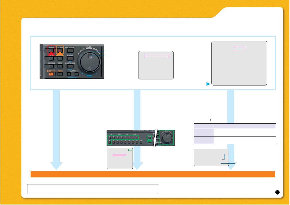
Within the OSD screen, use the jog dial to display sub-menus and move the cursor. Turn the shuttle ring
clockwise to select an entry. Turning it counterclockwise will bring up the previous screen.
Set the Month, Day, Hour and Minute.
“NTSC”
Set the Day, Month, Hour and Minute.
“PAL”
To enter the time, use the jog dial or buttons
1 through 9, and the QUAD button.
Press the [EXIT/OSD] button. The setting is completed and the display returns to the normal screen.
• Setting the time
Press the [MENU] button.
Select “1. INITIAL SET”
Select the “1. LANGUAGE/CLOCK SET”
<LANGUAGE/LANGUE/IDIOMA>
ENGLISH
<CLOCK SET>
01-01-2005 SAT 00:00:00
<DAYLIGHT SAVING>
MODE : USE
WEEK MONTH TIME
ON 1ST-SUN 04 02:00
OFF LST-SUN 10 02:00
<EXT. CLOCK SET>
ADJUST. TIME 01:00
<LANGUAGE/LANGUE/IDIOMA> [KEY]
ENGLISH
<CLOCK SET>
01-01-2004 THU 00:00:00
<DAYLIGHT SAVING>
MODE : USE
WEEK MONTH TIME
ON 1ST-SUN 04 02:00
OFF LST-SUN 10 02:00
<EXT. CLOCK SET>
ADJUST. TIME 01:00
Select the language
LANGUAGE:
ENGLISH / FRANCAIS / ESPAÑOL
“NTSC”
ENGLISH / FRANCAIS / DEUTSCH /
ESPAÑOL
“PAL”
• Changing the language
<INITIAL SET>
1. LAUNGUAGE/CLOCK SET ->
2. CAMERA DETECT ->
3. TITLE SET ->
4. HOLIDAY SET ->
5. TIME PERIOD SET ->
MOVE:JOG SELECT:SHUTTLE
<DAYLIGHT SAVING>
MODE : USE
WEEK MONTH TIME
ON 1ST-SUN 04 02:00
OFF LST-SUN 10 02:00
<EXT. CLOCK SET>
ADJUST. TIME 01:00
Setting range for WEEK and TIME:
WEEK: 1st to 4th. and LST
TIME 01:00 to 22:00
Set the compensation time
for Daylight Saving Time.
USE
Setting Description
Time is automatically adjusted to daylight
saving time. “NTSC”
Time is not automatically adjusted to
daylight saving time. “NTSC”
NO USE
Be sure to set the time before use. Recording is not possible unless the time has been set.
Language/Clock set
Jog dial
Shuttle ring
2
The sign [KEY] will appear at
the top-right corner whenever a
key entry is possible.
• Setting the daylight saving time
Setting the summer time “PAL”
<DAYLIGHT SAVINGS> “NTSC”
[<SUMMER TIME SET> “PAL”]
“MODE” “USE”
Page 4
DSR-5016 series Quick Operation Guide
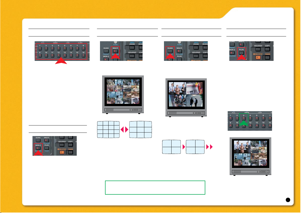
Multi 9/16 screen
Press the [MULTI] button. Press the [QUAD] button.
To view video from other cameras,
press the [QUAD] button again.
PLUS screen
Viewing on monitor 2
Live monitoring
Press the [MON2] button.
The MON2 indicator lights up.
Full-screen, quad screen display, multi-screen
display and automatic screen switching functions are available. When an alarm signal is
received, it is possible to automatically switch
the Monitor 2 screen display to the location
where the alarm came from. Only live video can
be displayed, not the playback video.
1234
5678
910
13 1411151216
123
456
789
12
34
56
78
Full-screen / Zoom function
Press the [CAMERA SELECT] button.
Playing video on quad screens
The Video from 16 separate cameras is displayed simultaneously.
Press the [MULTI] button again to
display multi 9 screens.
Press the [PLUS] button.
Enlarges the video from a single
camera to quad screen size during
multi 9 or multi 16 screen display.
Press the [CAMERA SELECT] button for the camera of whose image
is to be viewed in the PLUS screen.
To return to multi 9/16 screen display, press the [PLUS] button again.
To return to full screen display, press a
[CAMERA SELECT] button.
It is possible to move the zoom frame using
the jog dial. First, use the jog dial to adjust the
horizontal position and set it by turning the
shuttle ring clockwise. Then adjust the vertical
position of the frame with the jog dial and set it
by turning the shuttle ring clockwise.
3
To expand the screen being
monitored: Press the [ZOOM]
button while monitoring.
Pressing the [ZOOM] button again will
bring back the normal screen.
Page 5
DSR-5016 series Quick Operation Guide
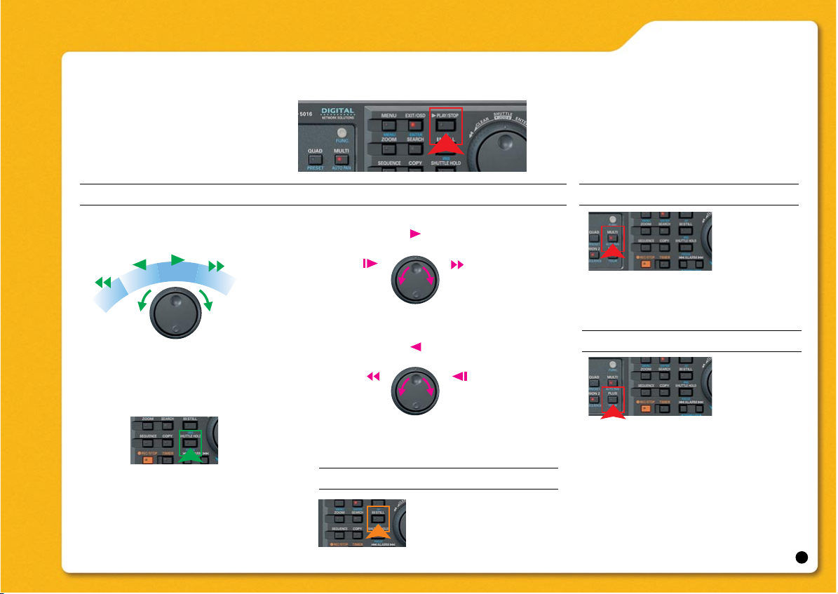
Press the [PLAY/STOP] button
Playback
Various playback methods
By turning the jog dial left and right, fast forward, fast rewind can be done easily.
Turning the shuttle ring during playback Turning the jog dial during playback
Turning the jog dial during reverse playback
To hold the shuttle ring, press the
[SHUTTLE HOLD] button. To release
the ring, press the [SHUTTLE HOLD]
button again.
Playback will start.
Pressing the [PLAY/STOP] button again
will stop the playback.
Multi-screen display (9/16 screen)
PLUS screen
Field advance, forward and reverse
Press the [MULTI] button.
To return to full screen display, press a
[CAMERA SELECT] button.
Press the [PLUS] button during playing
video on full, quad, multi 9 or multi 16
screens.
Press the [CAMERA SELECT] button for
the camera, whose image needs to be
enlarged.
Press the [PLUS] button again to return
to multi 9 or multi 16 screen display.
4
FF playback
FR playback
Reverse
playback
Play
FF playback
x2 FF playback
FR playback
Reverse
playback
Play
Slow-motion
Reverse slow-motion
Play
x2 FR playback
Reverse playback
To advance the picture
field by field, turn the jog
dial after pressing the
[STILL] button.
Page 6
DSR-5016 series Quick Operation Guide
Record set
Select
“2. RECORDING AREA SET”
Select
“RECORDING AREA”
Select “AUTO DELETE”.
• OVERWRITE • AUTO DELETE
(1)
(2)
(3)
(4)
(5)
<RECORDING AREA SET>
TOTAL CAPACITY
INTERNAL HDD
EXTERNAL HDD
RECORDING AREA
AREA FULL RESET ->
ARCHIVE AREA
AREA FULL RESET ->
CAUTION: WHEN THE AREA SETTING IS CHANGED,
THE WHOLE AREA WILL BE INITIALIZED !
<RECORDING DURATION BASE>
RECORDING DURATION : -- DAYS
TIMER RECORDING (DLY) : OFF
START --:-- STOP --:-PICTURE QUALITY : ENHANCED
AUDIO RECORDING : OFF
NUMBER OF CAMERAS : 2
REC RATE : ------FPS/CAM
<RECORDING CONDITIONS SET>
RECORDING AREA
OVERWRITE : ON
ARCHIVE AREA
MODE :
MANUAL COPY
REMAINING DISK WARNING
: **
AUTO DELETE : OFF
Select
“1. NORMAL REC EASY SETUP”
When “RECORDING DURATION BASE” is
selected:
Select desired value for the
“RECORDING DURATION”.
TIMER ON/OFF When the timer is ON, set the time.
Setting “PICTURE QUALITY” and
“AUDIO RECORDING”
Turn the shuttle ring counterclockwise until
the warning screen is displayed.
Select “Yes” and return to
“1.NORMAL REC EASY SETUP” screen.
Select “ON” for “OVERWRITE”.
• NORMAL REC EASY SETUP• RECORDING AREA SET
<RECORD SET>
1.NORMAL REC EASY SETUP ->
2.RECORDING AREA SET ->
3.RECORDING CONDITIONS SET ->
4.NORMAL REC MODE SET ->
5.PROGRAM REC SET ->
6.TIMER SET ->
7.ALARM REC MODE SET ->
8.ALARM OPERATION SET ->
MOVE:JOG SELECT:SHUTTLE
Press the [EXIT/OSD] button. The setting is completed and the display returns to the normal screen.
Press the [MENU] button.
Select the “2. RECORD SET”
(1) The total capacity of the hard disk.
(2) The internal hard disk capacity.
(3) The expansion unit hard disk capacity
(will not be displayed unless an external device is connected)
(4) Sets the capacity of the recording areas.
(5) The capacity of the archive area
Select “3. RECORDING CONDITIONS SET”
Set the storage period for recorded
data to “OFF” or within the range of
“1 DAY to 99 DAYS” (full days).
Archive area
Recording areaRecording areaRecording area
Select “REC RATE BASE” or
“RECORDING DURATION BASE”.
OFF: Recording is stopped when
the normal recording area becomes
full.
ON: Overwriting automatically starts
from the beginning of the recording
area when it becomes full.
5
If further details
need to be set, perform the setting
from “4.NORMAL
REC MODE SET”.
Set the recording area (Max.99%). Resetting
the area will initialize the hard disk.
When the recording area is designated by
percentage, the archive area is automatically
configured.
Overwriting is activated
in the recording area.
Within the OSD screen, use the jog dial to display sub-menus and move the cursor. Turn the shuttle ring
clockwise to select an entry. Turning it counterclockwise will bring up the previous screen.
2200GB
600GB
1600GB
99 %
:
:
:
:
:
1 %
Page 7

Alarm recording
Select one of the modes in the
following table.
Pre-alarm recording Post-alarm recording
alarm signal
Up to 15 minutes
time
<ALARM REC MODE SET>
ALARM RECORDING : OFF
PICTURE QUALITY : ENHANCED
PICTURE QUALITY ->
AUDIO RECORDING : OFF
ALARM INTERLEAVE : ONLY
REC RATE: 15FPS, DURATION: 20SEC
PRE-ALARM RECORDING : ***
REC RATE: **** FPS, DURATION: 1MIN
ALARM TRIGGER : ALARM
MOTION SENSOR ->
Select
“PRE-ALARM RECORDING”.
Select ON or OFF.
DSR-5016 series Quick Operation Guide
• Pre-alarm recording
• Alarm recording
OFF
ON
Setting Description
Press the [EXIT/OSD] button. The setting is completed and the display returns to the normal screen.
Press the [MENU] button.
Select “2. RECORD SET”.
Select “7. ALARM REC MODE SET”
Alarm recording is disabled.
Alarm recording is enabled only during the
time set in the timer setting. Normal
recording is not enabled.
AL-REC ON
TIMER
ENABLED
OFF
Setting Description
AL-REC OFF
TIMER
OLY AL-RC
ON TMR
Alarm recording is enabled regardless of
whether or not timer recording is enabled.
Alarm recording is enabled only during
timer recording.
Alarm recording is enabled only when
timer recording is disabled.
* “OLY AL-RC ON TMR” can be enabled simply by making
a timer setting. Accordingly, there is no need to press the
[TIMER] button.
Pre-alarm recording is disabled.
Pre-alarm recording is enabled.
Select
“MOTION SENSOR”.
• Motion sensor
Select “ALARM TRIGGER”.
Select one of the modes in the
following table.
• Alarm trigger
Setting Description
ALARM
SENSOR
ALARM AND
SENSOR
ALARM OR
SENSOR
Alarm recording is performed when
either the external alarm*1 or a
motion sensor is activated.
Alarm recording is performed when
an external alarm*1 occurs.
Alarm recording is performed when
a motion sensor detects movement.
( P.99)
Alarm recording is performed when
both the external alarm*1 and a
motion sensor are activated
simultaneously.
When it is set to ON, proceed
to set “DURATION”.
6
CH01 T-1 LEVEL : OFF MODE : A
The setting screen for the
sensor appears.
Set the values for “PICTURE QUALITY”,
“AUDIO RECORDING”, etc.
For further details, refer
to the Instruction Manual, pages 99 to 102.
Within the OSD screen, use the jog dial to display sub-menus and move the cursor. Turn the shuttle ring
clockwise to select an entry. Turning it counterclockwise will bring up the previous screen.
Page 8

DSR-5016 series Quick Operation Guide
Timer recording
Press the [TIMER] button.
24
hour
Recording is done for the set time periods.
12
Record Record
• TIMER REC settings
After completing the TIMER REC settings:
The start/stop time for recording can be set using the timer function.
(1) (2) (3) (4) (5) (6)
(7)
<TIMER SET>
WEEK START STOP PROGRAM FPS SET
SUN
MON
TUE
WED
THU
FRI
SAT
DLY
EXT
Press the [MENU] button.
Select “2. RECORD SET”
Select “6. TIMER SET”
(1) WEEK
(2) START
(3) STOP
(4) PROGRAM
This column is used to enable timer recording using
the program function “P-1” through “P-4”.
(For further details, refer to Instruction Manual p.85.)
(5) FPS
This column is used to set the recording rate.
(6) SET
This column is used to set timer recording to “ON” or
“OFF”.
(7) Settings for timer recording of over 24 hours
Use these lines for timer recording spanning more
than 24 hours. (For further details, refer to Instruction
Manual p.90.)
1 day
--:--
--:--
--:--
--:--
--:--
--:--
--:--
--:--
*****
--:--
--:--
--:--
--:--
--:--
--:--
--:--
--:--
*****
15 FPS
15 FPS
15 FPS
15 FPS
15 FPS
15 FPS
15 FPS
15 FPS
15 FPS
OFF
OFF
OFF
OFF
OFF
OFF
OFF
OFF
OFF
OFF
OFF
OFF
OFF
OFF
OFF
OFF
OFF
OFF
7
Pressing the [MENU RESET] button under the CF slot will clear the settings.
To stop the timer recording before the programmed stop time, press the [TIMER] button.
Within the OSD screen, use the jog dial to display sub-menus and move the cursor. Turn the shuttle ring
clockwise to select an entry. Turning it counterclockwise will bring up the previous screen.
Make settings as required.
Press the [EXIT/OSD] button.
The setting is completed and
the display returns to the
normal screen.
Page 9

DSR-5016 series Quick Operation Guide
• Alarm log search
Search functions
Alarm Log OSD the month
Select the week, day and the hour
Select the ALARM SEARCH or ALARM THUMBNAIL SEARCH
DD-MM-YY 1 5 10 15 20 25 30
01
02
03
04
05
06
07
08
09
10
11
12
13
14
15
16
SEARCH:ALARM
< ALARM LOG SEARCH > TERM : MONTH
Time
axis
TERM
SEARCH
Use the following procedure to perform an alarm search or alarm
thumbnail search by defining the period (month, week, day or time)
of the alarm recorded video.
Press the [SEARCH] button while the digital video recorder is
recording or stopped.
Select “ALARM LOG SEARCH”.
Select the value for “TERM”. (Month / Week / Day / Hour)
Select the date, time or minute.
Selected day (hour or minute) is indicated with a yellow frame.
Select "ALARM" or "THUMBNAIL".
Press the [FUNC.] button to search for normal record-
ing. A blue mark is displayed at the top left of the screen,
and normally recorded parts are displayed in blue. (The
search for normal recording may take some time.)
Turning the jog dial
will move the cursor.
To move to the preceding / following
month, press the [ALARM] buttons.
8
The alarm log search will start
from the current month.
Finally, select the time of
images that need to be reviewed
Within the OSD screen, use the jog dial to display sub-menus and move the cursor. Turn the shuttle ring
clockwise to select an entry. Turning it counterclockwise will bring up the previous screen.
Page 10

DSR-5016 series Quick Operation Guide
Search functions
Press the [SEARCH] button while the
digital video recorder is recording or stopped.
Input a camera number
to search.
Input the date and the time
to search.
0000028 0000027 0000026
0000025 0000024 0000023
0000022 0000021 0000020
0000028 0000027
0000026
0000025 0000024
0000023
0000022 0000021
0000020
Press the [SEARCH] button again to exit from the search mode.
< TIME/DATE SEARCH >
RECORDING TOP : 05-10-04 18:00
RECORDING END : 05-10-04 19:00
CHANNEL : 01
SEARCH :
DATE TIME
10-15-03 12:32
PREVIEW ->
VIEW ->
MOVE:JOG SELECT:SHUTTLE
<SEARCH>
ALARM LOG SEARCH ->
ALARM SEARCH ->
ALARM THUMBNAIL SEARCH ->
TIME/DATE SEARCH ->
ARCHIVE AREA SEARCH ->
MOTION DETECTION SEARCH ->
MOVE:JOG SELECT:SHUTTLE
• Alarm thumbnail search
• Time/date search
Select “ALARM THUMBNAIL SEARCH”
This screen lists the nine most recent alarm recordings. An alarm
number and camera number are indicated together with each
alarm recording, and the number of the currently selected recording flashes.
Select the video for playback.
Search and play back video in the recording area (normal recording, timer recording, alarm recording) by specifying camera
number, date, or time.
Turn the jog dial to select
“TIME / DATE SEARCH”
Press the
[CAMERA SELECT]
button.
Enter the date and time.
Select “VIEW”.
Press the
[FUNC.] button.
SEARCH :0000028
CHANNEL :--
9
Searches for an alarm recording and plays it back. When pre-alarm recording is included, it is possible to view images just before the alarm
event.
The user is then
allowed to select a
recording by the number (entered from the
keypad). Changing
the camera number is
also possible.
Within the OSD screen, use the jog dial to display sub-menus and move the cursor. Turn the shuttle ring
clockwise to select an entry. Turning it counterclockwise will bring up the previous screen.
Page 11

DSR-5016 series Quick Operation Guide
Within the OSD screen, use the jog dial to display sub-menus and move the cursor. Turn the shuttle ring
clockwise to select an entry. Turning it counterclockwise will bring up the previous screen.
External media storage
• Copying to a CompactFlash card or Microdrive • Copying to a CD-R/RW or DVD+R/+RW
Insert a CompactFlash card.
Specify the media to which the image is copied.
Select “COMPACTFLASH” for “COPY TO”.
Specify the volume to be copied.
Connect a CD or DVD writer and insert a disc.
Specify the media to which the image is copied.
Select “DISK WRITER” for “COPY TO”.
Specify the volume to be copied.
PICTURES
TIME
MAXIMUM
COPY START ->
FORMAT / ERASE : COMPACT FLASH
FORMAT / ERASE START ->
CHANGE:JOG SET:SHUTTLE
or
or
DVD+R/+RW CD-R/RW
Play video to be copied on a full screen.
Press the [STILL] button when the
frame to be copied is displayed.
Press the [COPY] button.
The maximum number of images allowable in the copy destination is copied or all the
data from the copy source is copied.
The specified number of images after specified location are copied.
The specified duration after the specified location is copied (TIME:minutes:seconds).
Setting Description
CompactFlash Microdrive
SANYO VA-EXD1 B
Disabled when an external device is
not connected.
10
Recorded video is copied to a CompactFlash card or Microdrive. Recorded video is copied to a DVD+R/+RW or CD-R/RW disc.
For further information for connection with disc drives supplied
by other manufacturers, consult the place of purchase.
To cancel the copying during the process,
press the [COPY] button again.
COPY TO : COMPACT FLASH
UNIT : PICTURES
AUDIO : OFF
HOW MANY
: 20
Page 12

DSR-5016 series Quick Operation Guide
Within the OSD screen, use the jog dial to display sub-menus and move the cursor. Turn the shuttle ring
clockwise to select an entry. Turning it counterclockwise will bring up the previous screen.
Camera telemetry control
This page explains the settings and operations that are available when a dome camera controllable from a coaxial cable is
connected to a VIDEO terminal.
• Camera telemetry control settings
Press the [MENU] button.
Select “8. ADVANCED MENU SET”
Select “3. CAMERA CONTROL SET”
Select the camera number for the
dome camera.
Select the protocol.
Press the [EXIT/OSD] button.
The setting is completed and the display returns to the normal screen.
<CAMERA CONTROL SET>
PROTOCOL
SANYO COAX1
OFF
SANYO RS-485
OFF
OFF
2ND RS-485/422
OFF
PELCO COAX
2ND RS-485/422 PROTOCOL : KALATEL
ADD.
001
----003
-----
----006
-----
-----
CH
01
02
03
04
05
06
07
08
PROTOCOL
OFF
OFF
OFF
OFF
OFF
OFF
OFF
OFF
ADD.
-----
-----
-----
-----
-----
-----
-----
-----
CH
09
10
11
12
13
14
15
16
11
[MENU]
[ZOOM]
[AUTOPAN]
[SEQUENCE]
[TOUR]
[ZOOM ]
[ZOOM ]
[AF]
[SEARCH]
[MON2]
[PLUS]
[ ALARM]
[ALARM ]
[PLAY/STOP]
[MENU]
[EXIT/OSD]
[ENTER]
Button
Button name in
normal mode
Operation
Displays the camera menu screen.
Determines items on the camera
menu screen.
Press the [PRESET] button and
then the [CAMERA SELECT] button to move to a preset position.
Press the [FOCUS] button and use
[ZOOM ] or [ZOOM ] button to
manually adjust the focus.
Press the [IRIS] button and
use [ZOOM ] or [ZOOM ]button
to adjust the iris (aperture).
Enables auto panning
Enables automatic camera selection
Enables TOUR
Zooms out
Zooms in
Enables auto focus
Controls manual panning
Controls manual tilting
PAN
TILT
Shuttle dial
Jog dial
Press the [CAMERA SELECT] button to select the camera and display
its image in full screen.
Press the [FUNC.] button.
The FUNC. indicator lights up and
camera operation mode is activated.
[PRESET]
[FOCUS]
[Shuttle HOLD]
[IRIS] [STILL]
Page 13

DSR-5016 series Quick Operation Guide
Within the OSD screen, use the jog dial to display sub-menus and move the cursor. Turn the shuttle ring
clockwise to select an entry. Turning it counterclockwise will bring up the previous screen.
ROI
• Setting ROI
Select one of the recording modes in which ROI is enabled.
NORMAL REC
ALARM REC
NORMAL/
ALARM
Static ROI recording (8KB)
• Static ROI recording
Determine the area of ROI and make settings to enhance
the area's picture quality.
BASIC mode (8KB)
Use the same amount of data …
for enhancing the picture quality
of regions of interest
Active ROI recording (8KB)
BASIC mode (8KB)
Active ROI
Using this function activates the ROI settings only
if motion is detected in the ROI areas.
Setting Description
ROI is enabled during normal and alarm recording.
ROI is enabled during normal recording.
ROI is enabled during alarm recording.
12
Select “AREA/SENSITIVITY”
(To be continued …)
Even with
the same file
size …
Press the [MENU] button.
Select “8. ADVANCED MENU SET”
Select “1. ROI SET”
Select the camera number
to set ROI.
Set “QUALITY” for “STATIC AREA
1 to 3”: MIN, LOW, OFF, HIGH,
MAX
Set “ACTIVE ROI” to ON or OFF.
Select the “EFFECTIVE REC MODE”
Page 14

DSR-5016 series Quick Operation Guide
Within the OSD screen, use the jog dial to display sub-menus and move the cursor. Turn the shuttle ring
clockwise to select an entry. Turning it counterclockwise will bring up the previous screen.
•The cursor is on the top left position.
•Turn the shuttle ring. The symbol “ ” appears on the top right of the screen, which
means you can move the cursor to left or right.
To move the cursor up or down, press the [FUNC.] button and the symbol “ ” will
change to “ ”.
•Before resizing the ROI area, it is necessary to determine the direction of setting an
area (starting at the top left corner and ending at the bottom right corner, or vise versa).
Use the shuttle ring to switch the direction.
ROI
• Setting the ROI area
CH01 T-1 LEVEL: OFF TIME LAG: OFF
Select "T-1" at the bottom of ROI setting screen.
Set either "LEVEL" or "TIME LAG".
After “AREA / SENSITIVITY SET” ,
turn the shuttle ring counterclockwise.
Press the [EXIT/OSD] button.
The setting is completed and the display
returns to the normal screen.
Select the time period to be applied to the ROI.
T-1
T-2
T-3
T-4
“T-1” through “T-4” are the times of TIME PERIOD A or
TIME PERIOD B set on the <TIME PERIOD SET> screen.
Time period T-1
Time period T-2
Time period T-3
Time period T-4
Setting Description
OFF
1 - 10
Setting Description
Response sensitivity is enabled. Lower
numbers correspond to higher levels of
sensitivity.
Response sensitivity is disabled.
OFF
1S - 10S
Setting Description
No operation after the response-stop
Time lag after the response-stop (seconds)
CH-1 T-1 LEVEL : OFF TIME LAG: OFF
1
2
Move the cursor to change
the position of the ROI area.
(For further details, refer Instruction Manual p.139.)
13
Press the [MENU] button.
Select “8. ADVANCED MENU SET”
Select “1. ROI SET“
Select “AREA / SENSITIVITY SET”
Once the ROI Area 1 is set, ROI Area 2 will be ready for setting.
Follow the same procedure to set ROI Area 2.
Turning the jog dial will move
the cursor toward upper-left or
lower-right direction.
CH01 T-1 LEVEL: OFF TIME LAG: OFF
Page 15

DSR-5016 series Quick Operation Guide
Within the OSD screen, use the jog dial to display sub-menus and move the cursor. Turn the shuttle ring
clockwise to select an entry. Turning it counterclockwise will bring up the previous screen.
Security lock
Use the following procedure to restrict operation of the digital
video recorder based on the user level.
• Setting the security lock
• Cancelling the key lock
Press the [MENU] button.
Select “3. GENERAL SET”
Select “3. SECURITY LOCK SET”
Select “LOCK MODE”
Select “OPERATION AUTHORITY”
Select “CHANGE” if it is necessary to change the user privileges.
The cursor will move to “COPY” after the selection.
<SECURITY SET>
LOCK MODE : KEY
FREE ACCESS LEVEL : NON
OPERATION AUTHORITY : NORMAL
COPY : LV2,3,4
CAMERA CONTROL : LV2,3,4
USER ID SET ->
LV1:LIVE, LV2:PLAY, LV3:REC, LV4:MENU SET
LV1 LV2 LV3 LV4
Four different levels of operation privileges are provided as follows.
Level
Operation
privilege
Menu operation
Monitoring
Playback /
searching
Recording
Make settings as required.
Press the [EXIT/OSD] button.
Setting Description
KEY
PASSWORD
NETWORK
Control the DVR from a PC on a network.
All key operations are locked. When keys are pressed while
locked, buzzer is sounded.
Password lock is enabled. When keys are pressed while locked,
the input screen for user ID and password is displayed and operation restrictions are restricted according to ID level.
NORMAL
CHANGE
Setting Description
Changes copying to external media and camera control privileges.
User privileges remain at the default setting.
[KEY]
PASSWORD LOCKED !
(LOCKED LEVEL: LV4,3,2,1)
PLEASE ENTER YOUR ID AND PASSWORD.
USER ID ***
PASSWORD ****
LV1:LIVE, LV2:PLAY, LV3:REC, LV4:MENU SET
14
Depending on the setting for "FREE ACCESS LEVEL", the
operation privileges of ordinary users change.
Press the [SHUTTLE HOLD] button to start the security lock
process.
During key lock, press the [SHUTTLE HOLD] button for
approximately 3 seconds.
Enter the user ID and password.
Page 16

DSR-5016 series Quick Operation Guide
• Installing DVR Viewer • Installing JPEG2000 plug-in
Required for viewing images encoded in JPEG2000 format on a PC.
DVR Viewer2 and JPEG2000 plug-in are included in the CD-ROM that comes with the DSR-5016 series.
They are also provided on the website for downloading.
With IE ver. 5.5 or later, surveillance over a network is possible.
(Simultaneous access with IE is limited to max. 15 connections.) For network settings, refer to Instruction Manual p.155.
This enables the user to view the surveillance video on a PC over a network
Sanyo website URL http://www.sanyosecurity.com
Network
Unzip the downloaded DVR Viewer software package and then
double click on the “Setup.msi” icon.
Installer will start.
In the “Start Copying File” window, confirm the destination folder to which files are copied.
Click “Next>”.
When the “Install shield Wizard Complete” window appears,
click “Finish”.
This will complete the installation.
Click
How to install the JPEG2000 and ActiveX Plug-in software
1) Download “JPEG2000 Plug in_1.0.0.zip” file on your PC.
2) Unzip the file and “JPEG2000 Plug in_1.0.0.zip” folder will appear.
3) Run “J2KPlng_en.msi” in the “JPEG2000 Plug in_1.0.0.zip”
folder.
4) Follow the instructions.
Note:
• Zipped files can be decompressed with Winzip or a similar decompression utility.
A free evaluation version of Winzip can be downloaded at
www.winzip.com.
• If the JPEG2000 and ActiveX Plug-in software are already installed,
remove them from the computer before installing the latest version.
15
Page 17

DSR-5016 series Quick Operation Guide
Click the button on the operation panel.
This will stop the playback and switches the
display to live images being monitored.
For designating the camera number to be
displayed Green buttons indicate cameras that
are controllable.
For switching the display to multi-screen or
quad-screen
For various playback operations
For recording
Network
• Camera remote control• Monitoring live video during playback
For controlling pan/tilt of the camera
Network screen
LV1 connection, LIVE (16-screen),
with two cameras connected
Click
For calling up preset motions
Clicking the "CAMERA
CONTROL" button will bring
back the normal display.
16
Page 18

DSR-5016 series Quick Operation Guide
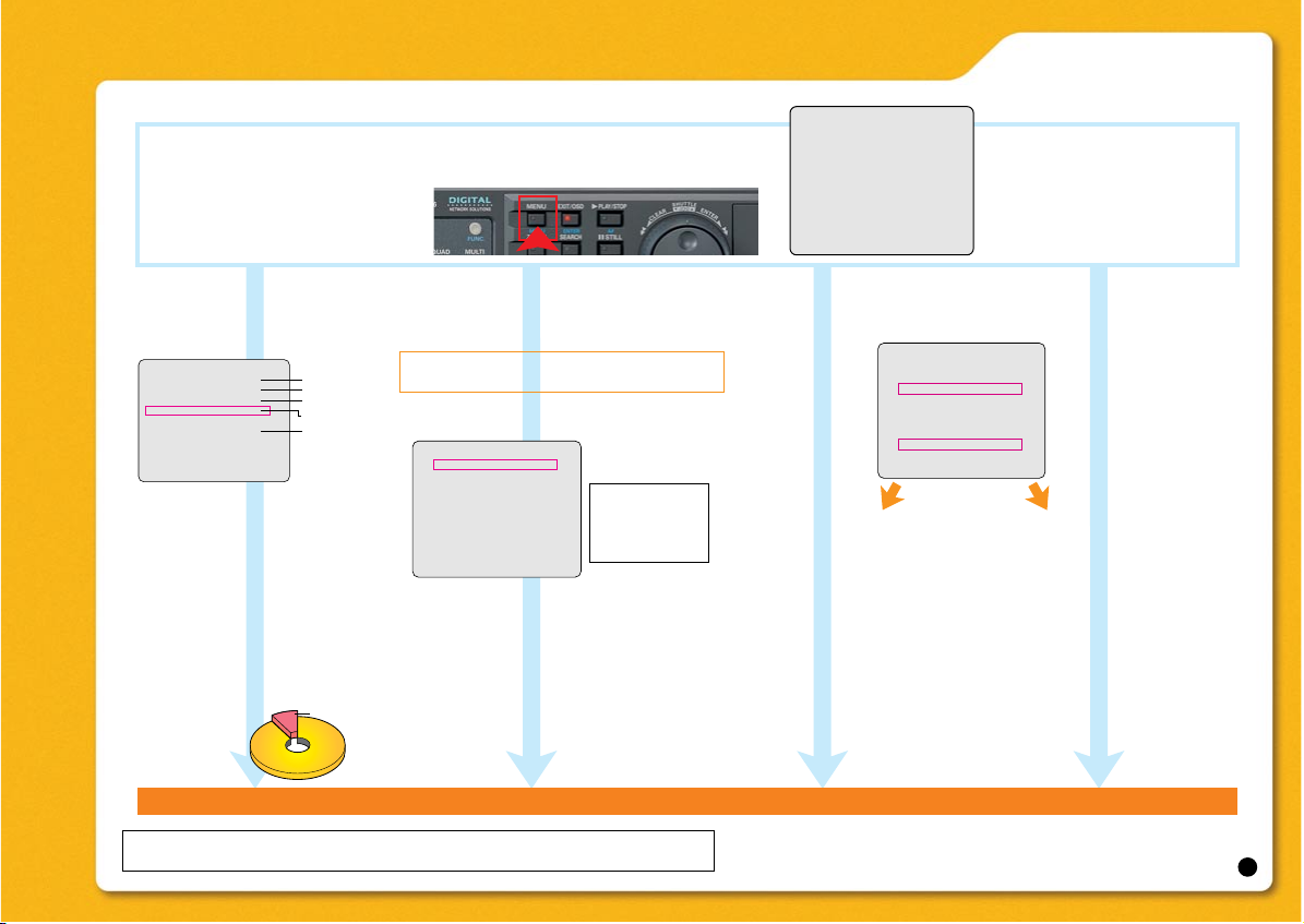
• Displaying the menu screen
Click
From the main menu, open desired menu item. Make necessary settings
Clicking here will
bring back the live
monitoring screen.
by opening each setting window.
Network
CLOCK SET
-- :
2005
01 01
DAYLIGHT SAVING/EXT. CLOCK SET
DAYLIGHT SAVING
MODE :
ON :
1ST
LST
EXT. CLOCK SET
ADJUST TIME
HOLIDAY SET
-
1 11
2 12
-
3 13
-
4 14
-
5 15
-
6 16
-
7 17
-
8 18
-
9 19
-
10 20
-
00 00
TUE
SET
USE
WEEK
MONTH TIME
SUN
04 02 00
SUN
:
SAVE
10 02 00
01:00
:
:
:
:
:
:
:
:
:
:
:
:
-
- OFF :
SAVE
17
Page 19

DSR-5016 series Quick Operation Guide
Management functions
Monitoring equipment remote setting function
Screen design that emphasizes ease of operation
User management system that emphasizes safety
Group management function
Log function for recording operating status
Data import/export functions
Comprehensive data management functions
Monitoring functions
Monitoring image multi-display
function
Wide variety of screen display
Convenient centralized monitoring
panel function
Camera control functions
Archive functions
Recorded image search function
Download data management functions
Download information listing function
• CCTV System Management Software VA-SW5000 settings
The software enables the user to monitor an assortment of video images
The software enables the user to monitor an assortment of video images
from various remote locations on a PC
from various remote locations on a PC
& 2+I #$ ,84I
& 2+I #$ ,84I
(4096 Cameras)
(4096 Cameras)
VA-SW5000
Monitoring
Monitoring
Monitoring functions
Monitoring functions
・Monitoring image multi-display
・Monitoring image multi-display
function
function
・Wide variety of screen display
・Wide variety of screen display
・Convenient centralized monitoring
・Convenient centralized monitoring
panel function
panel function
・Camera control functions
・Camera control functions
VA-SW5000
Management
Management
Management functions
Management functions
・Monitoring equipment remote setting function
・Monitoring equipment remote setting function
・Screen design that emphasizes ease of operation
・Screen design that emphasizes ease of operation
・User management system that emphasizes safety
・User management system that emphasizes safety
・Group management function
・Group management function
・Log function for recording operating status
・Log function for recording operating status
・Data import/export functions
・Data import/export functions
・Comprehensive data management functions
・Comprehensive data management functions
Archive
Archive
Archive functions
Archive functions
・Recorded image search function
・Recorded image search function
・Download data management functions
・Download data management functions
・Download information listing function
・Download information listing function
HUB
DATA
Recording, Camera control
ID/PASS
VA-SW5000
System log-on
for DVR log-on
Master computer
HUB
Internet
HUB
VA-SW5000 VA-SW5000 VA-SW5000 VA-SW5000
Slave computer (1) Slave computer (7)
System operations
Enables control of
dome cameras
Connects up to
eight PCs
Connects up to 256
DVRs
The operations allowed on each PC depend on the security setting.
*Exclusive software for following models
DSR-5016 / DSR-3716 / DSR-3709 / DSR-3506 “NTSC”
DSR-5016P / DSR-5009P / DSR-3716P / DSR-3709P / DSR-3506P “PAL”
18
Page 20

DSR-5016 series Quick Operation Guide
• CCTV System Management Software VA-SW5000 screens
VA-SW5000
Setting screen
Almost all settings of DVRs and
cameras can be performed over
a network.
Group management of users
and DVRs is possible.
Main monitoring screen
Images from connected DVRs are displayed
as tags. The main monitor screen can be
configured from camera images supplied by
different DVRs.
Lists of downloaded data
Four different levels for user
management
19
 Loading...