

Page 1

INSTRUCTION MANUAL (Supplement)
DSR-5016PA
DSR-5009PA
Digital Video Recorder
with Multiplexer Function
Additions and changes to the Manual
GB
Parts of the manual have additions and changes as a result of revisions to the product
specifications. Make sure to check this supplement for additions and/or changes when
referring to the relevant pages in the manual.
Page 2

Contents
1 Additions and Changes to Main Unit Operating Procedures ....................2
Supplementary Explanation on Image Search Times (P35 - 48/P169 - 174) ..................... 2
About Changes to the Copy Function's Standard Behavior (P50 - 55) ............................ 2
Changes to the Folder Hierarchy (P53, 57) ......................................................................... 4
Forcible Interruption of Recording (P58) ............................................................................. 5
Changes to the Display of Monitor 2 upon Alarm Detection (P104) ................................. 5
Improvements to the Image Quality Checks for the ROI Settings (P142) ........................ 6
About Support for Coaxial Control (P145) .......................................................................... 6
Alarm Recording Trigger Settings (P145) ........................................................................... 6
How to Register Preset Positions (P147) ............................................................................ 7
2 Additions and Changes to Network Operations .........................................8
Changes to the “Copy to Archive Area” Function's Standard Behavior (P174) .............. 8
Support for Multi-channel Download (P175) ....................................................................... 9
Alarm Recording Trigger Settings (P202) ........................................................................... 9
Newly Added Alarm Notification Menus (P201) ................................................................ 10
3 DVR Viewer2 Operation Guide (P205 - 210) ..................................................11
Before Using DVR Viewer2 ................................................................................................. 11
Structure of the Screen and the Function of each Section ............................................. 12
Opening Image Files ............................................................................................................13
Switching the Display Pattern of the Screen .................................................................... 14
Selecting the Channel Displayed on the Screen .............................................................. 14
Functions of the Viewer Operating Panel .......................................................................... 15
Saving and Printing Images................................................................................................. 16
Setting the Date and Time Display Format ........................................................................ 16
4 Other Additions and Changes ...................................................................17
About Specifications (P213) ............................................................................................... 17
About Terminal Board Specifications (P219) .................................................................... 17
OpenSSL License ................................................................................................................17
Numbers in parentheses indicate the corresponding pages in the instruction manual.
English 1
Page 3

1 Additions and Changes to Main Unit Operating Procedures
Supplementary Explanation on Image Search
Times (P35 - 48/P169 - 174)
When you use the image search function directly from the
main unit or via the network operation search menu, it may
take one or more minute for the search function to return
results depending on the available hard disk space and the
amount of the recorded data.
About Changes to the Copy Function's
Standard Behavior (P50 - 55)
1 Changes to the basic configuration menu (P50,
52, 54)
When you press the [COPY] button with a still image
displayed, you are first presented with the copy setting
screen. Note that the menus on this screen have been
changed as follows:
COPY TO : ARCHIVE AREA
UNIT : PICTURES
AUDIO : OFF
HOW MANY : 1
COPY CH 01 02 03 04 05 06 07 08
09 10 11 12 13 14 15 16
SELECT COPY CHANNEL
COPY START ->
FORMAT/ERASE: COMPACT FLASH
FORMAT/ERASE START ->
1 Support added for event-by-event copying
When copying from the archive area, you can now use
the “EVENTS” option added to the “UNIT” setting item.
By choosing “EVENTS”, you can copy as many images
as your specified events.
Use the “HOW MANY” item to specify the number of
events within the range of 1 to 99.
2 Upper limit raised for saved copies
Now you can specify more copies than in the previous
release using the “HOW MANY” item with “UNIT” set to
“PICTURES”:
Previous release: 1 to 60 copies
Current release: 1 to 99 copies
3 Support added for multi-channel copying
Now you can copy video simultaneously from multiple
channels.
A channel selection menu has been added to the copy
setting screen. Select your desired channels using the
[CAMERA SELECT] buttons on the front panel.
1
2
3
(added)
2 About copying to an external disc (P54)
New menus are added that appear when “COPY TO” is set
to “DISC WRITER”. Also, there are changes to the disc
detail screen, which appears upon start of copying.
COPY TO : DISC WRITER
TYPE : DVD+R
FREE AREA : 5000MB
NO. OF COPY : 1
FINALIZE : ON
VALIDATE : OFF
COPY START ->
The “DATA SIZE
3
” item was removed.
1 Support added for multi-session writes to the same
medium
Now you can use a new menu that allows you to turn on
or off the “FINALIZE” setting.
You can enable multi-session writes to the same medium
by setting “FINALIZE” to “OFF”.
[Settings] (
ON Finalizes the disc (disables multi-session writes).
OFF
indicates default setting)
Setting Description
Does not finalize the disc (enables multi-session
writes).
z You can carry out up to 99 write sessions to a CD-R/
DVD+R, or up to 99 write sessions within the same date
to a CD-RW/DVD+RW.
z Copying data requires at least 20MB of free space on a
disc.
z When the copy destination is a DVD+RW, the
“FINALIZE” setting is fixed to “OFF”.
z Data copied to a DVD+R in multi-session mode can only
be retrieved under environments that satisfy the
following:
Drive:
Drive with DVD multi-session/multi-border retrieval
support
OS:
Windows 2000 (with SP3 or later), Windows XP
1
2
(added)
[CAMERA SELECT] buttons
2 English
Page 4
Additions and Changes to Main Unit Operating Procedures1
2 Disc verification
Now you can use a new menu for disc verification.
You can verify and compare your disc during copying.
[Settings] (
OFF Does not verify or compare the disc.
VERIFY
VERIFY+
COMPARE
indicates default setting)
Setting Description
Verifies the disc to make sure that the data
residing on it can be retrieved.
Both verifies and compares the disc to make
sure that the data written onto the target disc is
identical to that on the source disc.
z When an error is detected during disc verification, you
are presented with a warning message that states either
“VERIFY ERROR” or “COMPARE ERROR”. Chances
are that your medium is defective or corrupted; replace it
with a new disc and try again.
z Warning messages can be dismissed by pressing any
button on the front panel or turning the jog or shuttle dial.
3 Removal of the DATA SIZE item
When the copy destination is “DISC WRITER”, the
“DATA SIZE” item no longer appears; this change is
intended to improve the performance.
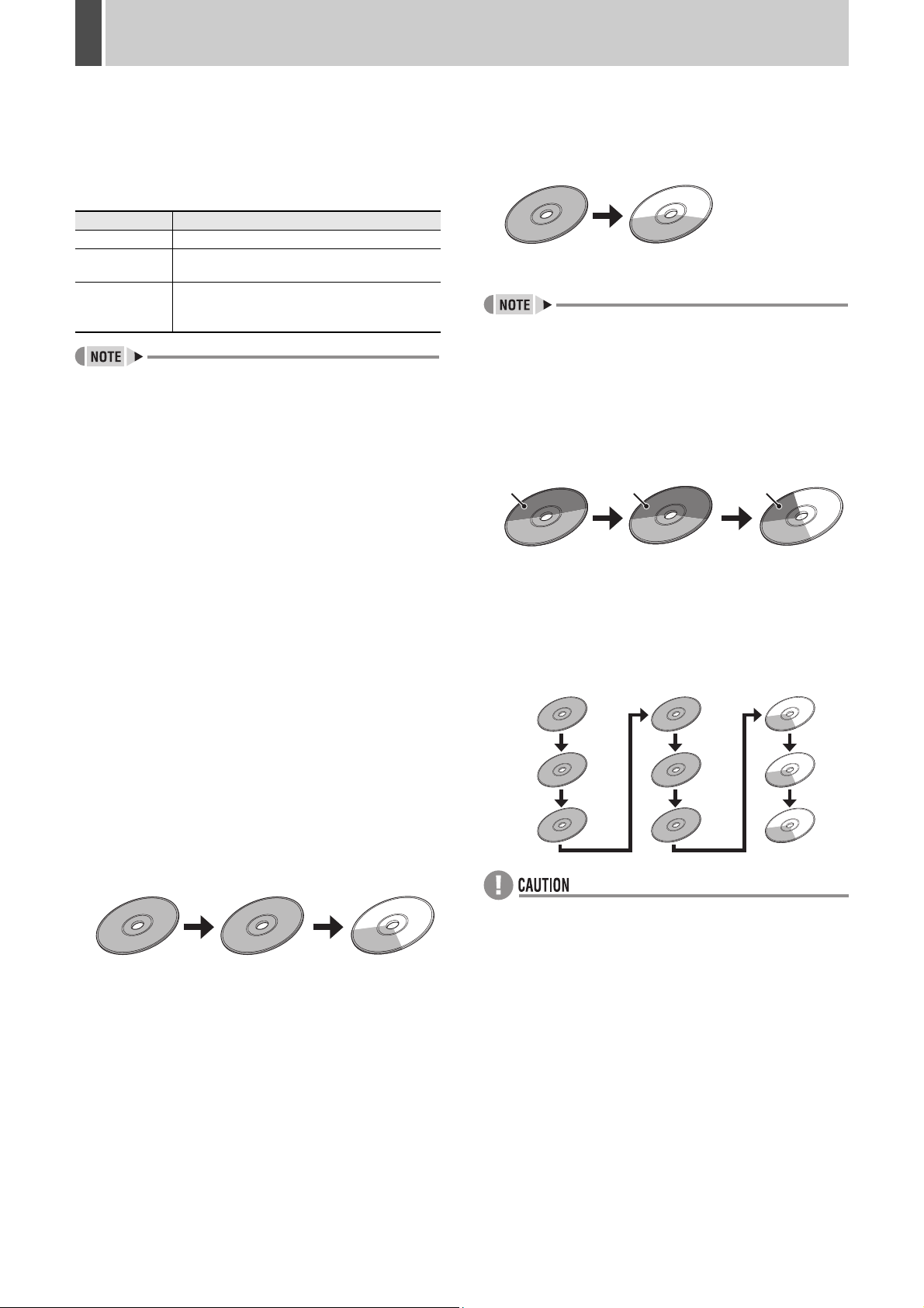
Example 2: This example illustrates how 5000MB data
can be copied to DVD+R (4700MB) and CDR (650MB) discs (one each):
1st disc 2nd disc
DVD+R
4700MB
CD-R
300MB
Support for copying across multiple discs is available
regardless of the target medium type (DVD or CD).
Example 3: This example illustrates how 3000MB data
can be multi-session written onto one
DVD+R (with 2500MB free space), CD-R
(with 300MB free space), and CD-R (with
500MB free space):
1st disc 2nd disc 3rd disc
Existing
data
DVD+R
(multi-session)
2500MB
Existing
data
CD-R
(multi-session)
300MB
Existing
data
CD-R
(multi-session)
200MB
3 Support for copying across multiple discs
(P54)
There are occasions when your data does not fit into one
disc. Now you can successively copy the remaining data to
new discs in such cases.
When the current disc becomes full, the disc tray is
automatically ejected and you are prompted to replace the
disc with a new one.
Example 1: This example illustrates how 1500MB data
can be copied across three CD-R (650MB)
discs:
1st disc 2nd disc 3rd disc
CD-R
650MB
CD-R
650MB
CD-R
200MB
Example 4:
This example illustrates how 1500MB data can
be copied to 9 CD-R discs (650MB each) with
“NO. OF COPY” set to 3:
1st disc 2nd disc 3rd disc
Copy 1
Copy 2
Copy 3
CD-R
650MB
CD-R
650MB
CD-R
650MB
CD-R
CD-R
650MB
650MB
CD-R
650MB
CD-R
650MB
CD-R
200MB
CD-R
200MB
CD-R
200MB
When you copy data across multiple discs with “NO.
OF COPY
”
set to a number larger than 1:
z All discs must be blank. This feature does not support
multi-session writes.
z Second and subsequent copies must be written onto
discs that are in capacity equal to or larger than the disc
for the first copy.
English 3
Page 5
Additions and Changes to Main Unit Operating Procedures1
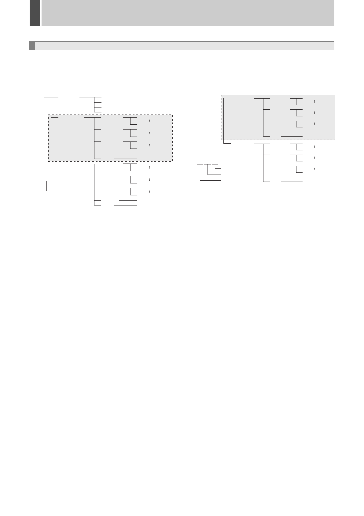
Changes to the Folder Hierarchy (P53, 57)
The following changes have been added to the folder hierarchy:
1 Folder hierarchy for data copied onto a
CompactFlash card (P53)
1st layer 3rd layer 4th layer2nd layer
SANYO _VIEWER
DDMMYY01
One data
saving
DDMMYY02
DDMMYY
Year
Month
Day
1. The first layer consists of a single folder named
“SANYO”, under which a number of session-specific
folders are created as the second layer.
2. The second layer consists of a number of sessionspecific folders that are named in this format: DDMMYY
(the recording date for the first image copied in the copy
session) followed by a two-digit serial number.
IJL15.DLL
J2KCOREX.DLL
VIEWER2.EXE
VIEWER2.INI
IMG00001
IMG00002
IMG00200
SOUND
INFO
IMG00001
IMG00002
IMG00200
SOUND
INFO
00000001.JP2
00000200.JP2
00000201.JP2
00000400.JP2
00039801.JP2
00040000.JP2
SOUND.MP3
DDMMYY01.INF
00000001.JP2
00000200.JP2
00000201.JP2
00000400.JP2
00039801.JP2
00040000.JP2
SOUND.MP3
DDMMYY02.INF
2 Folder hierarchy for data copied onto a CD-R/
RW or DVD+R/RW (P57)
1st layer 3rd layer 4th layer2nd layer
SANYO
AUTORUN.INF
IJL15.DLL
J2KCOREX.DLL
VIEWER2.EXE
VIEWER2.INI
DDMMYY
DDMMYY01
One data
saving
DDMMYY02
Year
Month
Day
1. The first layer consists of a single folder named
“SANYO”, under which a number of session-specific
folders are created as the second layer.
2. The second layer consists of a number of sessionspecific folders that are named in this format: DDMMYY
(the recording date for the first image copied in the copy
session) followed by a two-digit serial number.
IMG00001
IMG00002
IMG00200
SOUND
INFO
IMG00001
IMG00002
IMG00200
SOUND
INFO
00000001.JP2
00000200.JP2
00000201.JP2
00000400.JP2
00039801.JP2
00040000.JP2
SOUND.MP3
DDMMYY01.INF
00000001.JP2
00000200.JP2
00000201.JP2
00000400.JP2
00039801.JP2
00040000.JP2
SOUND.MP3
DDMMYY02.INF
3. The third layer consists of a number of image storage
folders that are named in this format: IMG followed by a
5-digit serial number. Each of these folders can contain
up to 200 image files that make up the fourth layer.
4. For image files with sound, the corresponding MP3 files
are stored in the “SOUND” folder.
5. The “INFO” folder is created on a session by session
basis, and it contains configuration information files.
6. As part of the second layer, a folder named “VIEWER” is
created, and it contains viewer-related files including
“IJL15.DLL”, “J2KCOREX.DLL”, “VIEWER2.EXE”, and
“VIEWER2.INI”.
3. The third layer consists of a number of image storage
folders that are named in this format: IMG followed by a
5-digit serial number. Each of these folders can contain
up to 200 image files that make up the fourth layer.
4. For image files with sound, the corresponding MP3 files
are stored in the “SOUND” folder.
5. The “INFO” folder is created on a session by session
basis, and it contains configuration information files.
6. Viewer-related files including “AUTRUN.INF”,
“IJL15.DLL”, “J2KCOREX.DLL”, “VIEWER2.EXE”, and
“VIEWER2.INI” are directly placed in the first layer.
4 English
Page 6
Additions and Changes to Main Unit Operating Procedures1
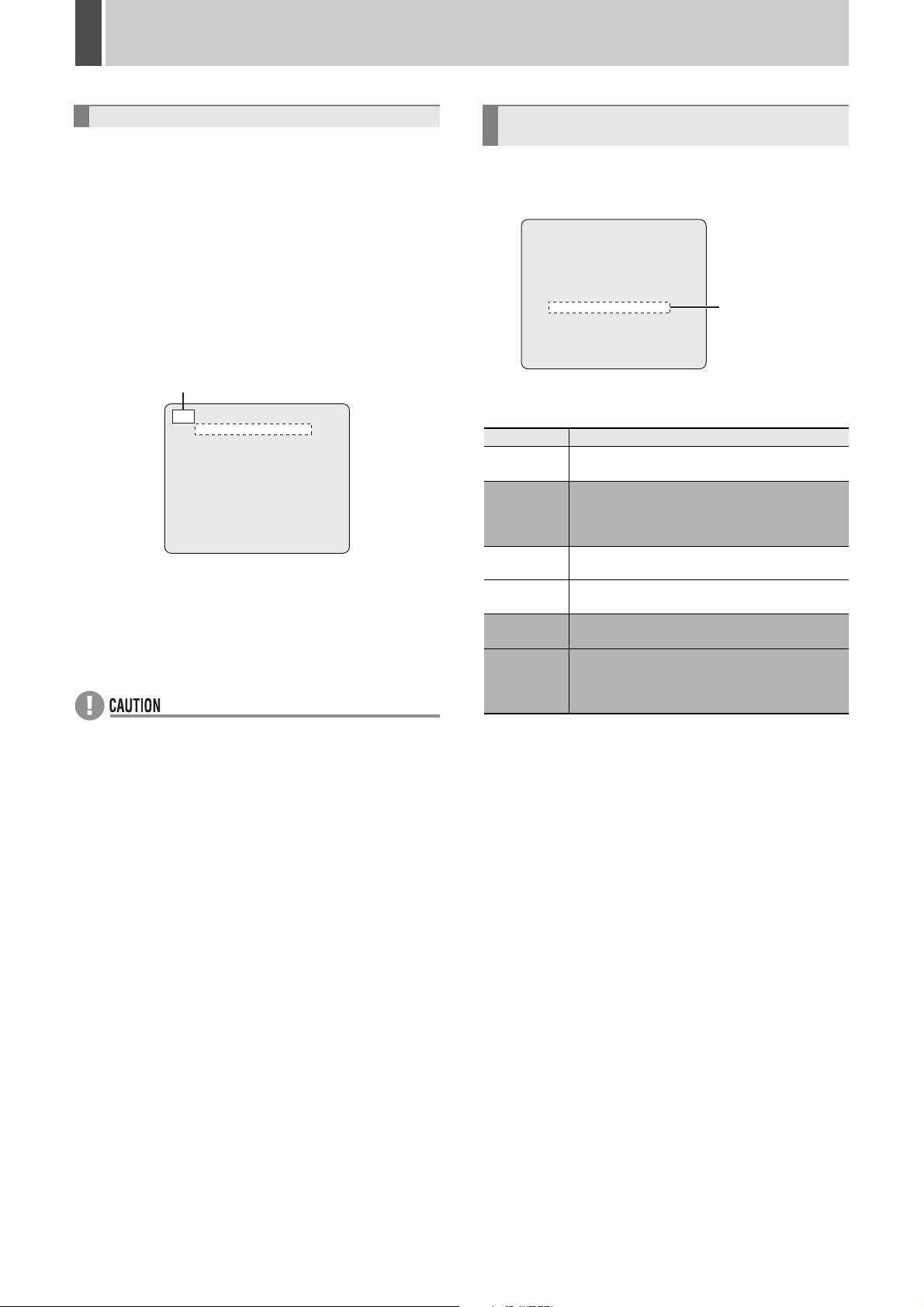
Forcible Interruption of Recording (P58)
Now you can forcibly interrupt the current recording session
while the <MAIN MENU> screen is displayed. Using this
feature, you can change the menu settings without changing
the current recording conditions.
z To interrupt the current recording session:
Press and hold the [SHUTTLE HOLD] button for about 3
seconds.
☞ The recording indicator turns off, and all the recording
mechanisms (normal, timer, and alarm) are switched to
pause mode. During pause, you can change the menu
settings.
While the recording session is paused,
a <--> mark is displayed on the menu screen.
<--> <MAIN MENU>
1.INITIAL SET ->
2.RECORD SET ->
3.GENERAL SET ->
4.SCREEN SET ->
5.POWER LOSS/USED TIME ->
6.INITIALIZATION LOG ->
7.COPY MENU SETTINGS ->
8.ADVANCED MENU SET ->
MOVE:JOG SELECT:SHUTTLE
z To exit from pause mode:
Press the [EXIT/OSD] button.
☞ You are returned to the same recording status as before
you paused the recording session.
z While recording is paused, the DVR does not accept any
new recording command.
z If, with the recording session paused, you have
uploaded a menu setting file or a power failure has
occurred, the DVR does not resume the previous
recording status.
Changes to the Display of Monitor 2 upon
Alarm Detection (P104)
The following changes have been added to the “MON.2
DISPLAY” item on the <ALARM OPERATION SET> screen
under “RECORD SET”.
<ALARM OPERATION SET>
ALARM RETRIGGER : ON
MAIN MON. DISPLAY : FULL
ALARM PRIORITY : LAST
MON.2 DISPLAY : NC
[Settings] (
NC
SWITCH
(added)
9
16
LAST
(added)
FIRST
(added)
indicates default setting)
Setting Description
When an alarm is detected, the main monitor
does not change.
When a number of alarms occur, the display
switches between the video from the
corresponding cameras, showing each for one
second.
When an alarm is detected, the main monitor
appears in multi 9 screen display.
When an alarm is detected, the main monitor
appears in multi 16 screen display.
When a number of alarms occur, the most recent
alarm video is given priority and is displayed.
When a number of alarms occur, only the video
for the first alarm is displayed. However, if the
duration for the first alarm expires, video for the
next alarm is displayed.
(Settings changed)
English 5
Page 7

Additions and Changes to Main Unit Operating Procedures1
Improvements to the Image Quality Checks
for the ROI Settings (P142)
Now the ROI SET configurations made under “ADVANCED
MENU SET” are directly applied to the <AREA/
SENSITIVITY SET> screen.
On the <ROI SET> screen, set the picture quality in
“STATIC AREA”. Then move the cursor to “AREA/
SENSITIVITY SET”, and turn the shuttle dial clockwise. You
can check the new picture quality as it is applied to the
actual image.
<AREA/SENSITIVITY SET> screen
2
CH-01 T-1 LEVEL: OFF TIME LAG: OFF
Your new picture quality setting is applied
to the actual image displayed in the
“STATIC AREA”.
z The <AREA/SENSITIVITY SET> screen displays an
image in the recording mode configured in “EFFECTIVE
REC MODE”. When it is set to “NORMAL/ALARM”, the
screen displays an image in normal recording mode.
z You cannot check the picture quality on the <AREA/
SENSITIVITY SET> screen while recording is in
progress or prealarm recording is in effect.
1
3
Alarm Recording Trigger Settings (P145)
The camera control mechanism provides a new feature that
allows you to configure what camera action is triggered by
alarm detection. For example, you can automatically
change the camera lens orientation or initiate an automatic
panning or tour operation in response to alarm detection. To
configure the settings, follow these steps:
1 Display the <CAMERA CONTROL SET>
screen under “ADVANCED MENU SET”.
The following changes have been added to this screen.
<CAMERA CONTROL SET>
1. PROTOCOL/ADDRESS SET ->
2. ALARM REC TRIGGER SET ->
1 PROTOCOL/ADDRESS SET
This item has been renamed from “CAMERA CONTROL
SET,” however, the screen operation method remains
the same.
2 ALARM REC TRIGGER SET
This menu has been newly added for configuring alarm
recording trigger settings.
1
2
2 Choose “ALARM REC TRIGGER SET”,
and configure the triggered action for
each camera in the “ACTION” column.
About Support for Coaxial Control (P145)
Now the camera control mechanism supports “AUX”
commands for BBV coaxial control.
Command Operation
AUX1 Turns on/off the light.
AUX2 Turns on/off the wiper.
AUX3 Turns on/off the washer.
<ALARM REC TRIGGER SET>
CH ACTION CH ACTION
01 OFF 09 -------- 02 PRESET 2 10 -------- 03 PRESET 3 11 -------- 04 PRESET 9 12 -------- 05 PAN 13 -------- 06 TOUR 14 -------- 07 SEQUENCE 15 -------- 08 OFF 16 ---------
6 English
Page 8

Additions and Changes to Main Unit Operating Procedures1
3
[Settings] ( indicates default setting)
Setting Description
OFF No action triggered.
Moves the camera lens to the angle
PRESET
PAN Starts automatic panning.
TOUR Starts tour.
SEQUENCE Starts sequence.
z You can configure presets 2 to 9 for a 9-channel model
or presets 2 to 16 for a 16-channel model.
corresponding to your selected preset
number.
3 Press the [EXIT/OSD] button.
New settings are saved, and you are returned to the normal
screen.
z Before configuring trigger actions, be sure to configure
the settings under “ALARM REC MODE SET” and
“PROTOCOL/ADDRESS SET”.
z In the case more than one camera has issued an alarm
simultaneously, some or all trigger actions may fail to
operate correctly because only one camera can be
operated at a time.
z Actually available actions depend on each camera. For
more information, refer to the camera's instruction
manual.
How to Register Preset Positions (P147)
To register preset positions that are applied during camera
control, follow these steps:
1 Press the [FUNC.] button (1).
The FUNC. indicator lights up in blue to indicate that you are
now in camera control mode.
2 Set the camera lens orientation.
Adjust the lens to your desired orientation using the pan/tilt
functions.
3 Press and hold the [PRESET] button (2)
for about 3 seconds.
The buzzer beeps twice and the button indicator flickers (at
4Hz) to indicate that you are now in preset registration
mode.
4 Press one of the [CAMERA SELECT]
buttons (3) to specify the channel
number for the camera.
The button stops flickering, and the camera lens orientation
at the time of button press is registered as the preset
position.
Repeat steps 2 and 3 above to register the preset positions
for other cameras.
21
English 7
z Each preset number is associated with a specific
channel number.
For example, CH02 corresponds to PRESET 2.
Page 9

2 Additions and Changes to Network Operations
Changes to the “Copy to Archive Area” Function's Standard Behavior (P174)
Now you can navigate through the “COPY” screen menus and configure basic settings the same way as when you download
images.
3 Support added for multi-channel copying
Now you can copy simultaneously video from multiple
channels.
A menu for configuring channel settings has been added
to the “COPY” screen. Select the check boxes that
correspond to your desired channels.
z :
Selects all channels.
z :
Deselects all channels except the currently displayed
1
2
3
(added)
1 Changes to the “COPY” screen menus (P174)
channel.
z The check box for the currently displayed channel is
selected by default and cannot be deselected.
z The following items are fixed to particular settings and
cannot be selected.
z AUDIO: OFF
z COPY TO: ARCHIVE AREA
1 Support added for time-based copy ranges
Now you can specify the image copy range as a timebased range. To do so, choose “TIME” from “UNIT”.
[Settings] ( indicates default setting)
Setting Description
Specifies the copy range in terms of the
PICTURES
TIME
number of images.
☞In “PICTURES”, specify the number of
images.
Specifies the copy range as a time-based
range.
☞In “TIME”, specify your desired time.
2 Upper limit raised for the number of copies
Now you can use “PICTURES” to specify more copies
than in the previous release.
Previous release: 1 to 10000
Current release: 1 to 40000
2 Copy result dialog display (P174)
Upon completion of the copy operation you initiated by
clicking the [START] button, you are presented with a copy
result dialog similar to one that is displayed upon completion
of download.
When you click the [LIVE] button, you are returned to live
video.
8 English
Page 10

Additions and Changes to Network Operations2
Support for Multi-channel Download (P175)
Now you can download video simultaneously from multiple
channels.
(added)
Alarm Recording Trigger Settings (P202)
The camera control mechanism provides a new feature that
allows you to configure what camera action is triggered by
alarm detection. For example, you can automatically
change the camera lens orientation or initiate an automatic
panning or tour operation in response to alarm detection.
A menu for configuring alarm recording trigger actions (the
ACTION menu) has been added to the “CAMERA
CONTROL SET” screen under “ADVANCED MENU SET”.
Use this menu to configure the trigger action for each
camera.
(added)
A menu for configuring channel settings has been added to
the “DOWNLOAD” screen. Select the check boxes that
correspond to your desired channels.
z :
Selects all channels.
z :
Deselects all channels except the currently displayed
channel.
z The check box for the currently displayed channel is
selected by default and cannot be deselected.
[Settings] (
OFF No action triggered.
PRESET
PAN Starts automatic panning.
TOUR Starts tour.
SEQUENCE Starts sequence.
indicates default setting)
Setting Description
Moves the camera lens to the angle
corresponding to your selected preset
number.
z You can configure presets 2 to 9 for a 9-channel model
or presets 2 to 16 for a 16-channel model.
z Actually available actions depend on each camera. For
more information, refer to the camera's instruction
manual.
English 9
Page 11

Additions and Changes to Network Operations2
Newly Added Alarm Notification Menus (P201)
The following menu items have been added to the “ALARM NOTICE SET” screen under “ADVANCED MENU SET”.
These menu items are not available on the DVR side.
(added)
1
A
B
2
4
3
(added)
(added)
(added)
1 Support for SSL communications
Now you can send alarm notifications via SSL
communications.
[Settings] ( indicates default setting)
Setting Description
OFF Disables SSL support.
ON Enables SSL support.
2 Specifying the SMTP port number
Enter a port number you want to use for SMTP (send)
within the range of 0 to 65535. (Default: 25)
3 Specifying the POP3 port number
Enter a port number you want to use for POP3 (receive)
within the range of 0 to 65535. (Default: 110)
4 Sending warning notifications
You can configure the main unit to send warning notification
mail messages when the following problems are detected in
the functionality and operation of the main unit.
You can configure the warning notification feature the same
way as the alarm notification feature. All settings default to
“OFF”; turning “ON” an item causes the main unit to send
warning mail when the corresponding condition is detected.
z HDD:
The hard disk is faulty.
z V. LOSS:
The video signal is disconnected.
z FAN:
The fan is faulty.
z NON REC:
The DVR has stopped recording.
z FULL:
Any one of the recording areas on the hard disk has
reached the “remaining-space” warning level or has
become full.
z POWER:
The power has turned off and back on again.
z When you want to use the warning notification feature,
choose “ON” in the “ALARM NOTICE” column A.
z The “USE” column B controls the settings for alarm
notification, and does not affect the warning notification
feature. Regardless of the settings in the “USE” column,
notifications with “ON” settings are in effect.
10 English
Page 12

3 DVR Viewer2 Operation Guide (P205 - 210)
Before Using DVR Viewer2
DVR Viewer2, a playback-dedicated application, has been upgraded to Ver.2 with support added for multi-channel playback.
Use this section as your guide to DVR Viewer2 instead of the instruction manual provided in a separate volume when you use
DVR Viewer2 to play back the video and sound saved on an external medium such as a computer hard disk, CompactFlash
card, CD-R/RW, or DVD+R/RW.
● Operating Environment
Environment to be used
• CPU: Pentium® IV (2 GHz) or higher
• RAM: 256 MB or more (512 MB or more recommended)
• Compatible OS: Windows 2000/XP
• Compatible machines: PC/AT machines operating with
the above OS
• Display:
• Audio: Sound card and speakers compatible with
• Available languages: English or Japanese
• Supported formats:
Color (XGA 65536-color or higher recommended)
DirectX
JPEG2000 (image), MP3 (sound)
● Installing the Viewer Software
Follow the procedure below to install the software before
using it.
1 Insert the included CD-ROM in the computer CD-
ROM drive.
Or, if you have downloaded the latest release of DVR
Viewer2, decompress the compressed installation file.
● Internet Option Settings
Once the “DVR Viewer2” is fully installed, select Internet
Explorer, [Tools] → [Internet Options] → [Security].
If you click the [Custom Level] in the [Security] setting
screen, the [Security Settings] dialog pops up. Enable the
“ActiveX controls plug-ins”.
● Running and Quitting Viewer
1 Running DVR Viewer2.
To run Viewer, double click the shortcut icon on the
desktop or choose [Programs] → [SANYO] → [DVR
Viewer2] from the start menu.
z You can download the most recent version of the
software from our homepage.
Homepage address
http://www.sanyosecurity.com
2 Double click the installer icon.
The installer runs.
3 Select the language to be used for install and the
install destination following the instructions of the
installer.
The software starts installing.
4 Click [Finish] once the install is complete.
Once the “DVR Viewer2” is fully installed, a shortcut icon
appears on the desktop.
z When writing data from the DVR onto a CompactFlash
card or a CD-R/RW, DVD+R/RW, “DVR Viewer2” is
copied to the save destination.
z If an earlier version of Viewer software is installed on the
computer, before installing the present software,
uninstall the earlier version using [Add or Remove
Programs] under the control panel.
2 To quit Viewer.
To quit Viewer, click [Exit] from the file menu or click the
( ) button situated in the top-right corner of the screen.
English 11
Page 13

DVR Viewer2 Operation Guide3
Structure of the Screen and the Function of each Section
Running the Viewer software will result in the initial screen of the Viewer being displayed.
1
2
3
4
Initial screen
1 Menu bar
This is the basic menu of the Viewer software. Click
each menu to display the breakdown of each command.
1 2 3
1 File menu
Open:
The [Open] dialog is displayed.
Save:
To save playback still images.
Print:
To print playback still images.
Title Input:
To display the dialog that allows you to input the title of
the print image.
Exit:
To quit the Viewer software.
2 View menu
Toolbar:
To show/hide the toolbar.
Status bar:
To show/hide the status bar.
Camera Title:
To show/hide the camera title.
Date Display Format:
To set the date display format. (Refer to P16)
Time Display Position:
You can position the date and time display (bottomright/top-right/top-left/bottom-left) on the playback
images.
Image:
To specify the display pattern of the screen (1/4/9/16
screen). (Refer to P14)
3 Help
To display the version of the Viewer software.
2 Toolbar
Frequently used command bars are deployed.
1 2 3
1 To display the [Open] dialog.
2 To save playback still images in the bitmap format.
3 To print playback still images.
4 To switch the display pattern of the screen (1/4/9/16
screen).
5 To display the version of the Viewer software.
3 Viewer screen
The images of the loaded image files are displayed.
Right clicking on the screen will display the context
menu, which allows you to select the display pattern of
the screen (1/4/9/16 screen) and the display channel.
4 Viewer operating panel
It operates the playback of the images that are displayed
on the Viewer screen. (Refer to P15)
4
5
12 English
Page 14

DVR Viewer2 Operation Guide3
Opening Image Files
The image files are not displayed when the Viewer Software is run. Specify and open the playback file through the procedure
below.
1 Click in the toolbar.
Or, click “Open” in the file menu.
The [Open] dialog is displayed.
2 Click .
The [Browse for Folder] dialog is displayed.
3 Specify the folder in which the images
are saved and click [OK].
The folder specified in the [Open] dialog is displayed.
4 Verify the displayed folder and click
[OK].
The image file loads.
5 Screen display
The first image of the loaded file is initially displayed on full
screen.
01 09/29/2005 16:28:24
Refer to the appropriate pages for details about the
operations of the Viewer Screen.
z Switching the display pattern (1/4/9/16 screen) of the
playback images (Refer to P14)
z Selecting the channels displayed on each screen (Refer
to P14)
z Operating panel functions (Refer to P15)
English 13
Page 15

DVR Viewer2 Operation Guide3
Switching the Display Pattern of the Screen
The image display pattern can be selected from 4 patterns:
full screen, quad screen, 9 screen, 16 screen using the
toolbar button.
Toolbar
01 09/29/2005 16:28:24
Full screen
01 09/29/2005 16:28:24
02 09/29/2005 16:28:23
Selecting the Channel Displayed on the
Screen
Right clicking the Viewer screen will display the context
menu. Clicking the channel you want to display within the
context menu will switch the channel display.
When using the quad screen, the number of the channels
being viewed is displayed in [Channel] of the operating
panel.
Example: Displaying channel number 10 in the top
right screen
01 09/29/2005 16:28:24
03 09/29/2005 16:28:23
Quad screen
01 09/29/2005 16:28:23
02 09/29/2005 16:28:24
04 09/29/2005 16:28:24
9 screen
01 09/29/2005 16:28:23
02 09/29/2005 16:28:24 03 09/29/2005 16:28:24
16 screen
04 09/29/2005 16:28:23
03 09/29/2005 16:28:24
04 09/29/2005 16:28:24
Channel display of the displayed image
(Context Menu)
z The channel being currently displayed is checked on the
specified channel.
z Unchecking a channel results in the images of that
channel not being displayed but at least one image
display is necessary for each screen pattern, therefore
all the images on the screen cannot be turned off.
z The channel number of the image data that is not being
saved is not displayed in the context menu.
z Multiple channels cannot be selected.
z The images of each channel are played back
correspondingly.
Even when switching the displayed channel, if there is no
image data at the current point of playback, no images
will be displayed.
z The display pattern can also be selected from the menu
bar or from the context menu displayed on the screen.
z On the 4/9/16 screen, double clicking on a specific
image will display it on full screen.
14 English
Page 16

DVR Viewer2 Operation Guide3
Functions of the Viewer Operating Panel
The audio and image functions of the Viewer screen can be operated.
(Viewer Operating Panel)
1
3 4 5 6 72
1 Playback slide bar
The time stamp (recording date and time) of the start
and stop point of the playback file are displayed at both
ends of the slide bar.
Sliding the slide bar knob allows you to move the
playback point.
z Clicking the knob or sliding the knob while clicking it
displays the number of the image of the video being
displayed, on the cursor.
z Clicking a position that differs from the current playback
point using the slide bar will move the playback point by
one percent of the total number of images.
2 Operating buttons
Buttons that can be selected are black, buttons that are
currently in function are green.
: Rewinds to the previous image when the image is
on pause.
: Pauses the playback.
: Forwards to the next image when the image is on
pause.
: If the slide bar knob is positioned to the right of
the start point, the video can be played in reverse.
: If the slide bar knob is positioned to the left of the
stop point, the video can be played in sequence.
3 Playback speed adjusting section (Initial setting: 3)
Allows you to adjust the playback speed to 10 levels by
sliding the slide bar knob.
z Set the playback speed while playback is stopped.
z When playing back audio, audio is played back at the
rate at which it was recorded regardless of the [Playback
Speed] set.
4 Audio adjusting section
Allows you to turn on/off and adjust the volume of the
audio playback when a playback file contains audio
data.
3
1
1 Clicking the button turns the audio playback on and
off.
2 Sliding the knob allows you to adjust the audio
volume to 10 levels.
3 You can select the channel for audio playback (1ch/
2ch).
z Be sure to stop playback before you turn on/off audio
playback or switch the playback channel.
z Audio playback is only available when you are in the full
screen layout.
5 Channel display
The number of the playback channel of the images
being displayed is shown on full screen and quad
screen.
6 Time and date display
The time stamp (recording date and time) of the images
being viewed is displayed.
7 Image number display
The number of the “current image and the total number
of images” is displayed.
2
English 15
Page 17

DVR Viewer2 Operation Guide3
Saving and Printing Images
To save or print the image currently being displayed, switch
to “Full screen display” and perform the following
operations.
Saving images
Click in the toolbar or “Save” in the File menu.
The save dialog appears.
Specify the destination folder and file and click [OK]. The
image on the Viewer screen is saved in the bitmap format.
Printing Images
Click in the toolbar or click “Print” in the File menu.
The print dialog appears.
Set the printing conditions and click [OK]. The image on the
Viewer screen is printed full size.
Setting the Date and Time Display Format
Clicking the “Date Display Format” will display the [Date
Display Format] dialog. Set the format and delimiter and
click [Apply] and then [OK].
3
1
2
1 Display format (
To set the date display format.
indicates default setting)
Displaying a Title on the Image that is Printed
Click “Title Input” in the File menu.
The “Title Input” dialog appears. Type the title to be printed
in the input box and click [OK]. The title is displayed at the
bottom of the image when it is printed.
z The ten most recent input titles are saved which allows
you to choose a title using the pull down menu.
Selections:
MM/dd/yyyy (Month/Day/Year)
dd/MM/yyyy (Day/Month/Year)
yyyy/MM/dd (Year/Month/Day)
2 Delimiter (
Selections: / (Slash), - (Hyphen), . (Period)
3 Sample
When you change the display format or delimiter and
click [Apply], the sample (preview) is updated with the
new settings.
indicates default setting)
16 English
Page 18

4 Other Additions and Changes
About Specifications (P213)
The specifications indicated in the list have been partly revised.
Product number DSR-5016PA (16 channels), DSR-5009PA (9 channels)
Hard disk capacity Can be expanded using 80, 160, 250, 300 or 500GB hard disk (sold separately)
Video input terminal VBS/VS 1.0 V (p-p), 75 Ω, BNC (DSR-5016PA: x16, DSR-5009PA: x9)
Video output terminal Through output of each video input, BNC (DSR-5016PA: x16, DSR-5009PA: x9)
Alarm input terminals
Terminals
Current consumption 880 mA
Sensor alarm output terminals Open collector, Low level active (Max. 25 mA) (DSR-5016PA: x16, DSR-5009PA: x9)
Clock adjust output terminal Open collector, Low level active (Max. 25 mA)
About Terminal Board Specifications (P219)
The terminal board specifications indicated in the list have been partly revised.
Input/output terminals Signal level Input/output circuit
No-volt contacts (with a pulse width of 100 ms or more) (DSR-5016PA: x16, DSR-5009PA: x9)
CTL7 Clock adjust output
[Open collector 1kΩ, Low
level active]
Open
Approx. 1 second
OpenSSL License
The following license is applied to OpenSSL.
LICENSE ISSUES
==============
The OpenSSL toolkit stays under a dual license, i.e. both the conditions of
the OpenSSL License and the original SSLeay license apply to the toolkit.
See below for the actual license texts. Actually both licenses are BSD-style
Open Source licenses. In case of any license issues related to OpenSSL
please contact openssl-core@openssl.org.
OpenSSL License
---------------
/* ====================================================================
* Copyright (c) 1998-2003 The OpenSSL Project. All rights reserved.
*
* Redistribution and use in source and binary forms, with or without
* modification, are permitted provided that the following conditions
* are met:
*
* 1. Redistributions of source code must retain the above copyright
* notice, this list of conditions and the following disclaimer.
*
* 2. Redistributions in binary form must reproduce the above copyright
* notice, this list of conditions and the following disclaimer in
* the documentation and/or other materials provided with the
* distribution.
*
* 3. All advertising materials mentioning features or use of this
* software must display the following acknowledgment:
* “This product includes software developed by the OpenSSL Project
* for use in the OpenSSL Toolkit. (http://www.openssl.org/)”
*
* 4. The names “OpenSSL Toolkit” and “OpenSSL Project” must not be used to
* endorse or promote products derived from this software without
* prior written permission. For written permission, please contact
* openssl-core@openssl.org.
*
* 5. Products derived from this software may not be called “OpenSSL”
* nor may “OpenSSL” appear in their names without prior written
* permission of the OpenSSL Project.
*
IC
BU2090
1k
Terminal
English 17
Page 19

Other Additions and Changes4
OpenSSL License (continued)
* 6. Redistributions of any form whatsoever must retain the following
* acknowledgment:
* “This product includes software developed by the OpenSSL Project
* for use in the OpenSSL Toolkit (http://www.openssl.org/)”
*
* THIS SOFTWARE IS PROVIDED BY THE OpenSSL PROJECT ‘‘AS IS’’ AND ANY
* EXPRESSED OR IMPLIED WARRANTIES, INCLUDING, BUT NOT LIMITED TO, THE
* IMPLIED WARRANTIES OF MERCHANTABILITY AND FITNESS FOR A PARTICULAR
* PURPOSE ARE DISCLAIMED. IN NO EVENT SHALL THE OpenSSL PROJECT OR
* ITS CONTRIBUTORS BE LIABLE FOR ANY DIRECT, INDIRECT, INCIDENTAL,
* SPECIAL, EXEMPLARY, OR CONSEQUENTIAL DAMAGES (INCLUDING, BUT
* NOT LIMITED TO, PROCUREMENT OF SUBSTITUTE GOODS OR SERVICES;
* LOSS OF USE, DATA, OR PROFITS; OR BUSINESS INTERRUPTION)
* HOWEVER CAUSED AND ON ANY THEORY OF LIABILITY, WHETHER IN CONTRACT,
* STRICT LIABILITY, OR TORT (INCLUDING NEGLIGENCE OR OTHERWISE)
* ARISING IN ANY WAY OUT OF THE USE OF THIS SOFTWARE, EVEN IF ADVISED
* OF THE POSSIBILITY OF SUCH DAMAGE.
* ====================================================================
*
* This product includes cryptographic software written by Eric Young
* (eay@cryptsoft.com). This product includes software written by Tim
* Hudson (tjh@cryptsoft.com).
*
*/
Original SSLeay License
-----------------------
/* Copyright (C) 1995-1998 Eric Young (eay@cryptsoft.com)
* All rights reserved.
*
* This package is an SSL implementation written
* by Eric Young (eay@cryptsoft.com).
* The implementation was written so as to conform with Netscapes SSL.
*
* This library is free for commercial and non-commercial use as long as
* the following conditions are aheared to. The following conditions
* apply to all code found in this distribution, be it the RC4, RSA,
* lhash, DES, etc., code; not just the SSL code. The SSL documentation
* included with this distribution is covered by the same copyright terms
* except that the holder is Tim Hudson (tjh@cryptsoft.com).
*
* Copyright remains Eric Young’s, and as such any Copyright notices in
* the code are not to be removed.
* If this package is used in a product, Eric Young should be given attribution
* as the author of the parts of the library used.
* This can be in the form of a textual message at program startup or
* in documentation (online or textual) provided with the package.
*
* Redistribution and use in source and binary forms, with or without
* modification, are permitted provided that the following conditions
* are met:
* 1. Redistributions of source code must retain the copyright
* notice, this list of conditions and the following disclaimer.
* 2. Redistributions in binary form must reproduce the above copyright
* notice, this list of conditions and the following disclaimer in the
* documentation and/or other materials provided with the distribution.
* 3. All advertising materials mentioning features or use of this software
* must display the following acknowledgement:
* “This product includes cryptographic software written by
* Eric Young (eay@cryptsoft.com)”
* The word ‘cryptographic’ can be left out if the rouines from the library
* being used are not cryptographic related :-).
* 4. If you include any Windows specific code (or a derivative thereof) from
* the apps directory (application code) you must include an acknowledgement:
* “This product includes software written by Tim Hudson (tjh@cryptsoft.com)”
*
* THIS SOFTWARE IS PROVIDED BY ERIC YOUNG ‘‘AS IS’’ AND
* ANY EXPRESS OR IMPLIED WARRANTIES, INCLUDING, BUT NOT LIMITED TO, THE
* IMPLIED WARRANTIES OF MERCHANTABILITY AND FITNESS FOR A PARTICULAR PURPOSE
* ARE DISCLAIMED. IN NO EVENT SHALL THE AUTHOR OR CONTRIBUTORS BE LIABLE
* FOR ANY DIRECT, INDIRECT, INCIDENTAL, SPECIAL, EXEMPLARY, OR CONSEQUENTIAL
* DAMAGES (INCLUDING, BUT NOT LIMITED TO, PROCUREMENT OF SUBSTITUTE GOODS
* OR SERVICES; LOSS OF USE, DATA, OR PROFITS; OR BUSINESS INTERRUPTION)
* HOWEVER CAUSED AND ON ANY THEORY OF LIABILITY, WHETHER IN CONTRACT, STRICT
* LIABILITY, OR TORT (INCLUDING NEGLIGENCE OR OTHERWISE) ARISING IN ANY WAY
* OUT OF THE USE OF THIS SOFTWARE, EVEN IF ADVISED OF THE POSSIBILITY OF
* SUCH DAMAGE.
*
* The licence and distribution terms for any publically available version or
* derivative of this code cannot be changed. i.e. this code cannot simply be
* copied and put under another distribution licence
* [including the GNU Public Licence.]
*/
18 English
Page 20

1AC6P1P3036-L8HBD/XE (1205KP)
SANYO Electric Co., Ltd.
 Loading...