

Page 1
INSTRUCTION MANUAL
Digital Video Recorder
with Multiplexer Function
About this manual
Before installing and using this unit,
please read this manual carefully.
Be sure to keep it handy for later reference.
DSR-5016P
DSR-5009P
z Refer to the included CD-ROM for the German, French, Spanish and Italian “INSTRUCTION MANUAL”.
Page 2

PRECAUTION
WARNING: TO REDUCE THE RISK OF FIRE OR
ELECTRIC SHOCK, DO NOT EXPOSE THIS
APPLIANCE TO RAIN OR OTHER MOISTURE.
To avoid electrical shock, do not open the cabinet.
Refer servicing to qualified personnel only.
If the power supply cord (AC power cord) of this
appliance is damaged, it must be replaced. Return to a
SANYO Authorised Service Centre for replacement of the
cord.
Location
For safe operation and satisfactory performance of your
unit, keep the following in mind when selecting a place for
its installation:
Shield it from direct sunlight and keep it away from sources
of intense heat.
Avoid dusty or humid places.
Avoid places with insufficient ventilation for proper heat
dissipation. Do not block the ventilation holes at the top and
bottom of the unit. Do not place the unit on a carpet
because this will block the ventilation holes.
Install the unit in a horizontal position only.
Avoid locations subject to strong vibrations.
Avoid moving the unit between cold and hot locations.
Do not place the unit directly on top of a monitor TV, as this
may cause playback or recording problems.
For EU Users
Your SANYO product is designed and
manufactured with high quality materials
and components which can be recycled
and reused.
This symbol means that electrical and
electronic equipment, at their end-of-life,
should be disposed of separately from
your household waste.
Please dispose of this equipment at your local community
waste collection/recycling centre.
In the European Union there are separate collection
systems for used electrical and electronic products.
Please help us to conserve the environment we live in!
Avoiding Electrical Shock and Fire
Do not handle the power cord with wet hands.
Do not pull on the power cord when disconnecting it from
an AC wall outlet. Grasp it by the plug.
If any liquid is spilled on the unit, unplug the power cord
immediately and have the unit inspected at a factoryauthorised service centre.
Do not place anything directly on top of this unit.
SERVICE
This unit is a precision instruments and if treated with care,
will provide years of satisfactory performance. However, in
the event of a problem, the owner is advised not to attempt
to make repairs or open the cabinet. Servicing should
always be referred to your dealer or Sanyo Authorized
Service Centre.
CAUTION
Danger of explosion if battery is incorrectly replaced.
Replace only with the same or equivalent type
recommended by the manufacturer.
Discard used batteries according to the manufacture’s
instructions.
English 1
Page 3
INTRODUCTION
Main features
The digital video recorder records video from
monitoring cameras to its internal hard disk,
and it can display real video being monitored
in four, six, nine or 16 screens. Recorded video
can also be played back with multiple screens.
The DSR-5009P can only display split screen video in four,
six or nine screens.
In addition to the two internal hard disks,
expansion units can be added for four hard
disks. The hard disks can also be used for
mirroring.
Complete range of recording and playback
functions
z Simultaneous recording and playback of video at a
maximum 100 frames per second.
z Timer recording allows recordings to be made at different
times each day.
Alarm recording allows the actions of intruders to be recorded.
z
z Zoom allows a certain section of monitored and playback
video to be magnified.
z The video from specific cameras can be masked using a
black pattern to prevent it being monitored.
z Motion sensing can be used with each camera. Alarms can
be set up to record moving images.
z ROI allows recordings to be made with different picture
quality for each area on the screen.
Search function allows instant display of the
desired recording. (JP.35)
z Alarm log search allows efficient searching of large
volumes of alarms.
z Search in order of alarm occurrence.
z Search by thumbnail using alarm search.
z Search by date/time.
z Search within the archive area.
z Search for intruder motion using motion detection search.
Four-level user level function allows
restriction of users for data and equipment
management. (JP.110)
Complete with audiovisual connections.
z Allows multi image output to monitor 2.
z
Features a dual-system audio input and single-system audio
output, and allows the switching of the output channel.
z The front panel of the unit is equipped with VIDEO OUT
(same as MAIN MONITOR output terminal on the rear
panel) and AUDIO OUT terminals (same as the audio
output terminal on the rear panel) to easily connect to
commercially-available VCRs and DVD recorders.
z The output image from the S-VIDEO terminal is the same
as the main monitor image.
Expandable and can be connected to a PC.
z Recorded video can be copied to a CompactFlash card.
Connect a recommended recordable CD drive or DVD
drive to enable copying of recordings to a CD-R/RW or
DVD+R/+RW.
z A built-in LAN terminal provides support for network
control, thus facilitating live monitoring, playback, searches
and menu settings.
z Information on alarms and device malfunctions as well as
alarm images can be sent by e-mail.
z Dome cameras can be controlled by button operations on
the digital video recorder.
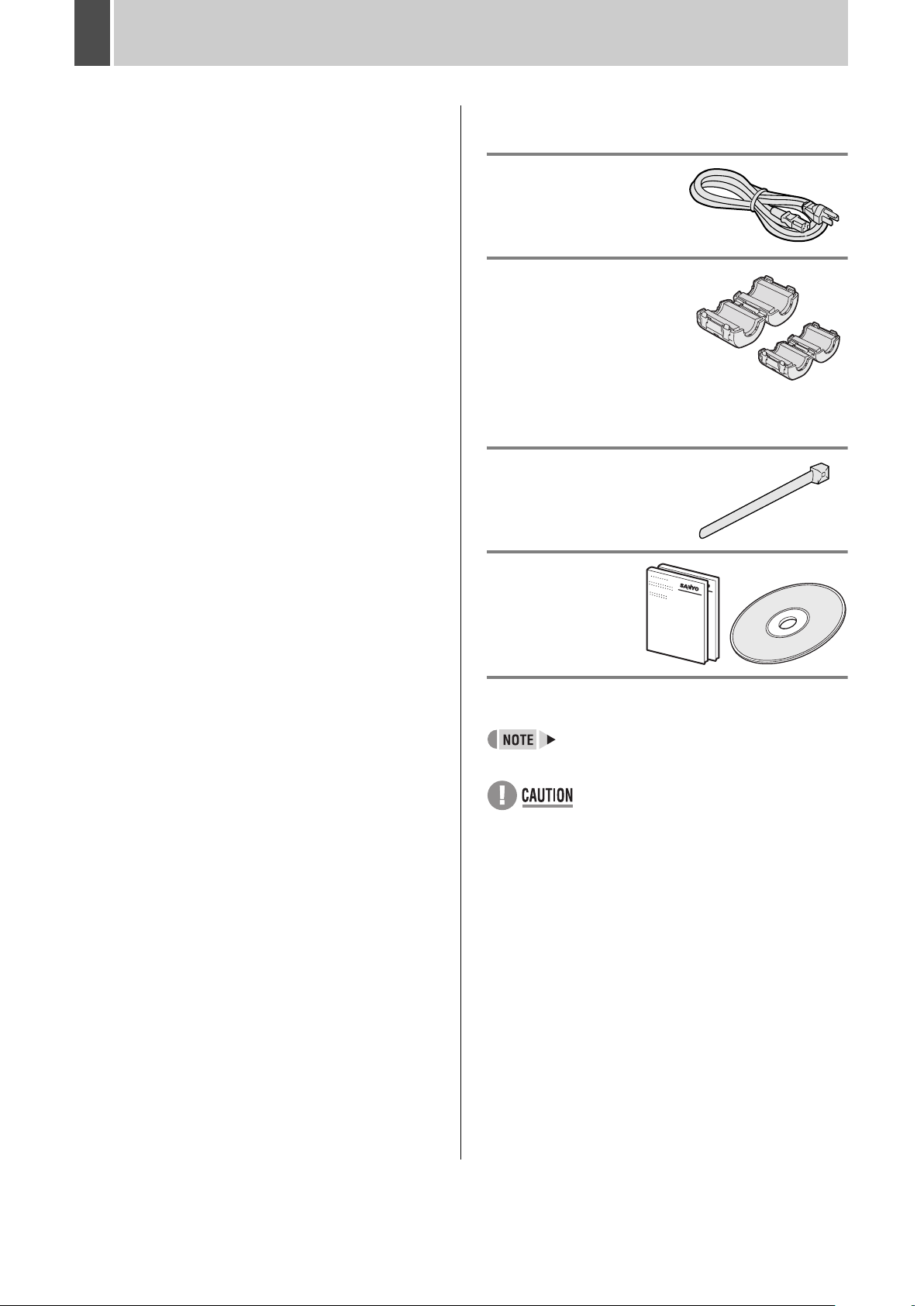
Accessories
Check that you have all the parts shown below.
Power cord
Core clamp
4 large, 2 small
For: DVR power cord (large)
LAN cable (large)
Main Monitor output
cable (large)
Alarm input and Sensor
alarm output cable (large)
RS-485 cable (small)
S-VIDEO output cable
(small)
Power cord tie
z
Instruction Manual
(DVR/Network)
z Quick Guide
z CD-ROM Manual
Symbols used in this manual
Information describing operation methods or
how to get the most out of functions.
Information describing the correct use of the
digital video recorder.
(JP.xx) indicates the page to be referred to.
Copyright
z This manual and software are copyrighted by Sanyo
Electric Co., Ltd.
z Brand and product names used in this manual are the
trademarks or registered trademarks of their respective
companies.
Except for personal use, copyright law prohibits the use of
recorded copyrighted images without the permission of the
copyright holder.
2 English
Page 4

CONTENTS
INTRODUCTION
1 BEFORE USE ................................................ 7
Notes on handling the internal HDD .............. 7
Notes on installation locations ....................... 7
The HDD and cooling fan are consumable
components. .................................................. 7
Important recordings ...................................... 7
Protection of the HDD .................................... 7
Backup battery ............................................... 8
2 NAMES AND FUNCTIONS OF PARTS ........ 9
Front panel ..................................................... 9
Rear panel ................................................... 11
OPERATION
1 PREPARING FOR USE ............................... 18
Operation display ......................................... 18
Changing the display position of
the operation display area ............................ 19
Changing the language ................................ 19
Setting the time ............................................ 20
Hard disk archive area ................................. 21
2 MONITORING VIDEO
FROM A CAMERA ...................................... 22
3 INSTALLATION AND CONNECTIONS ...... 13
Basic connections ........................................ 13
Connecting the RS-232C terminal ............... 13
Connecting RS-485 control terminals .......... 14
Connecting to a 2ND RS485/422 terminal ... 15
Connecting a LAN terminal .......................... 16
Connecting an amplifier ............................... 16
Connecting alarm input terminals ................. 16
Connecting SENSOR ALARM OUT
terminals ....................................................... 17
Connecting control terminals ........................ 17
Connecting the power cord .......................... 17
4 PLAY ............................................................ 31
Playing video on a full screen ...................... 31
Fast-forward and fast-rewind playback ........ 31
Changing the playback speed ...................... 31
Magnifying the playback video ..................... 32
Viewing still images ...................................... 33
Frame advance (forward/reverse) ................ 33
Playing video on multiple screens ................ 33
5 SEARCHING FOR RECORDED VIDEO ..... 35
Viewing on a full screen ............................... 22
Viewing on quad screens ............................. 23
Viewing on multi 9 or multi 16 screens ........ 24
Enlarging video ............................................ 24
Automatic camera selection ......................... 25
Viewing on monitor 2 ................................... 26
3 RECORDING ............................................... 29
Normal recording ......................................... 29
Timer recording ............................................ 29
Alarm recording ............................................ 30
Pre-alarm recording ..................................... 30
Alarm log search .......................................... 36
Alarm search ................................................ 37
Alarm thumbnail search ............................... 40
Time/date search ......................................... 42
Searching within the archive area ................ 44
Motion detection search ............................... 45
6 SAVING (COPYING)
RECORDED VIDEO .................................... 49
Copying video to the hard disk’s
archive area ................................................. 50
Copying to a CompactFlash card or
Microdrive ..................................................... 51
Copying to a CD-R/RW or DVD+R/+RW ..... 54
Viewing images on a PC .............................. 57
English 3
Page 5

CONTENTS
SETTINGS
MENU CONFIGURATION AND
OPERATIONS .................................................. 58
Basic menu operations ................................ 58
Resetting menu items .................................. 59
Sub-menu configuration ............................... 60
1 INITIAL SET ................................................ 61
Configuration ................................................ 61
Setting the language .................................... 62
Setting the time ............................................ 62
Setting the summer time .............................. 62
External clock setting ................................... 63
Detecting connected cameras ..................... 64
Setting camera titles .................................... 65
Setting holidays ............................................ 66
Setting time periods ..................................... 67
2 RECORD SET ............................................. 71
Configuration ................................................ 71
Normal recording easy setup ....................... 72
Displaying the recording areas .................... 77
Changing recording areas ............................ 78
Setting overwrite permission ........................ 79
Setting recording conditions ......................... 80
Setting auto deleting .................................... 82
Setting normal recording .............................. 83
Setting program recording ........................... 85
Timer settings .............................................. 87
Setting alarm recording ................................ 93
Setting the motion sensors .......................... 99
Setting alarm operation and display ........... 102
Canceling an alarm .................................... 105
3 GENERAL SET .......................................... 106
Configuration .............................................. 106
Setting data display .................................... 107
Setting display for video loss ...................... 108
Setting the buzzer ...................................... 109
Setting the security lock ............................. 110
Setting RS-232C and RS-485 .................... 115
Hard disk initialization and mirroring .......... 117
Expanding (Replacing) and
initializing the hard disk .............................. 119
Network settings ......................................... 120
Making network control settings ................. 123
4 SCREEN SET ............................................ 126
Setting quad and multi 9/16 display ........... 126
Setting the interval and monitors
for automatic screen selection ................... 128
Setting masks ............................................. 130
Setting the color level ................................. 132
5 POWER LOSS/USED TIME ...................... 133
6 INITIALIZATION LOG ............................... 134
7 COPY MENU SETTINGS .......................... 135
Saving menu settings ................................. 135
Loading menu settings ............................... 136
8 ADVANCED MENU SET ........................... 138
Configuration .............................................. 138
Setting ROI ................................................. 139
Setting alarm notification ............................ 144
Camera control settings ............................. 145
Making PPP settings .................................. 147
Time zone/NTP setting ............................... 149
INTRODUCTION SETTINGS NETWORK
CONTROL
NETWORK
OPERATION
NETWORK CONTROL
1 GETTING PREPARED .............................. 153
Operations possible with PC control .......... 153
Digital video recorder network settings ...... 153
2 NETWORK CONTROL .............................. 156
Controlling from a PC ................................. 156
Disconnecting ............................................ 157
Messages displayed when connected ....... 157
3 OPERATION PANEL FUNCTIONS AND
RESTRICTIONS ........................................ 159
Operation panel .......................................... 159
Camera operation panel ............................. 160
4 English
NETWORK
SETTINGS
OTHEROPERATION
Page 6

CONTENTS
NETWORK OPERATION
1 RECORDING IMAGES .............................. 162
Normal recording ....................................... 162
Timer recording .......................................... 162
Alarm recording .......................................... 162
Pre-alarm recording ................................... 162
2 WATCHING IMAGES ................................ 163
The various ways of displaying
live images ................................................. 163
Performing operations in play mode .......... 164
Adjusting the image and audio ................... 165
Screen display items .................................. 166
Downloading live images to a PC .............. 167
NETWORK SETTINGS
1 SETTINGS ................................................. 177
Making menu selections ............................ 177
Menu structure ........................................... 178
2 INITIAL SET .............................................. 179
3 SEARCHING FOR RECORDED VIDEO ... 169
Basic operation .......................................... 169
Search menu .............................................. 169
1. ALARM LOG SEARCH .......................... 170
2. ALARM SEARCH ................................... 171
3. ALARM THUMBNAIL SEARCH ............. 171
4. TIME/DATE SEARCH ............................ 172
5. ARCHIVE AREA SEARCH .................... 172
6. MOTION DETECTION SEARCH ........... 173
4 SAVING (COPYING)
RECORDED VIDEO .................................. 174
Copying to the archive area ....................... 174
Downloading to a PC ................................. 175
5 SCREEN SET ............................................ 196
1. SEQUENCE SET ................................... 196
2. MASK SET ............................................. 197
6 POWER LOSS/USED TIME ...................... 198
1. CLOCK SET ........................................... 179
2. SUMMER TIME SET/EXT.
CLOCK SET ........................................... 179
3. HOLIDAY SET ....................................... 180
3 RECORD SET ........................................... 181
1. RECORDING AREA SET ...................... 181
2. RECORDING CONDITIONS SET ......... 182
3. NORMAL REC MODE SET ................... 183
4. PROGRAM REC SET ............................ 184
5. TIMER SET ............................................ 185
6. ALARM REC MODE SET ...................... 186
4 GENERAL SET ......................................... 189
1. DISPLAY SET ........................................ 189
2. BUZZER SET ......................................... 189
3. SECURITY LOCK SET .......................... 190
4. USER ID SET ........................................ 191
5. RS-232C/RS-485 SET ........................... 192
6. HDD SET ............................................... 192
7. NETWORK SET ..................................... 193
8. NETWORK CONTROL SET .................. 194
1. POWER LOSS/USED TIME .................. 198
7 INITIALIZATION LOG ............................... 199
INITIALIZATION LOG ................................ 199
8 COPY MENU SETTINGS .......................... 200
SAVING MENU SETTINGS ....................... 200
LOADING MENU SETTINGS .................... 200
9 ADVANCED MENU SET ........................... 201
1. ALARM NOTICE SET ............................ 201
2. CAMERA CONTROL SET ..................... 202
3. PPP SET ................................................ 202
4. NTP SET ................................................ 203
English 5
Page 7

CONTENTS
OTHER
1 DVR VIEWER2 .......................................... 205
Operating environment .............................. 205
Installing DVR Viewer2 .............................. 205
Opening and closing DVR Viewer2 ............ 206
Menu structure ........................................... 207
Opening files .............................................. 207
Viewing images .......................................... 208
Printing images .......................................... 210
2 INTERFACE SPECIFICATIONS ............... 211
RS-485 specifications ................................ 211
RS-232C specifications .............................. 211
DVR/VCR command table ......................... 212
INTRODUCTION SETTINGS NETWORK
3 Specifications ........................................... 213
Specifications ............................................. 213
Dimensions ................................................ 214
UL disclaimer statement ............................. 214
Table of recording rates and times ............. 215
Table of recording rate settings .................. 217
Table of pre-alarm recording times ............ 218
Terminal board specifications .................... 219
4 MENU SETTING SEQUENCE ................... 221
INDEX .............................................................. 224
CONTROL
NETWORK
OPERATION
NETWORK
SETTINGS
OTHEROPERATION
6 English
Page 8

1 BEFORE USE
Notes on handling the internal HDD
This digital video recorder uses an internal HDD.
Be sure to observe the following points carefully when
operating, setting-up, or servicing the digital video recorder.
Do not subject the digital video recorder to
sudden impact or vibration.
If the digital video recorder is subjected to sudden impact or
vibration, it may damage the hard disk or cause corruption of
the data stored within it.
z Do not move the digital video recorder while the power is
turned on. Always ensure that the power is turned off
before removing the digital video recorder from or placing it
in a rack.
z When transporting the digital video recorder, pack it
securely using the specified materials. In addition, choose
a method of transportation that minimizes vibration.
z When placing the digital video recorder on the floor or
another similar surface, attach the specified pads to its
base and place it down gently.
Do not move the digital video recorder for 30
seconds after turning off the power.
After the power is turned off, the disk inside the HDD
continues to spin for a brief period due to inertia and the
heads are in an unstable condition.
During this period, the digital video recorder is even more
susceptible to damage from sudden impact and vibration than
when it is turned on. Make sure that the digital video recorder
is not subjected to even gentle vibration for at least 30
seconds after turning off the power.
Do not operate the digital video recorder when
condensation has formed on it.
If the digital video recorder is operated in this type of
condition, there is a possibility that it may become
permanently damaged.
If the temperature around the digital video recorder changes
suddenly, wait for it to stabilize before operating the digital
video recorder.
Notes on replacing the HDD
Be sure to follow the correct procedure when replacing the
HDD.
z HDDs that have been removed from their packing may not
operate correctly if they are subjected to sudden impact or
vibration. It is recommended that you place the HDD on a
soft, level surface with the printed circuit board facing
upward after it has been unpacked.
z Take care to avoid subjecting the HDD to sudden impact or
vibration when removing and tightening screws as part of
the HDD replacement procedure.
Tighten all screws securely to ensure that they do not
loosen.
z The HDD is sensitive to static electricity; accordingly, you
should take the appropriate precautions to prevent the
buildup of static charges.
Handling a detached HDD unit
If transporting or storing the HDD unit in a detached condition,
be sure to first of all pack it using the specified materials.
In addition, choose a method of transportation that minimizes
vibration.
Notes on installation locations
Avoid subjecting the HDD to sudden impact or vibration. In
addition, avoid using it in dusty locations or near magnetic
objects. The following precautions should be observed in
order to prevent the loss of recorded data:
Do not subject the digital video recorder to sudden impact.
z
z Do not use the digital video recorder on a vibrating or
unstable surface.
z Do not disconnect the power plug from the wall outlet
during recording or playback.
z Do not use the digital video recorder in areas with extreme
temperature changes (i.e., 10ºC or more per hour).
z Condensation may occur if the digital video recorder is
moved to an area with a significantly different temperature
or high humidity. If the digital video recorder is used with
condensation inside, operating problems may occur.
z Do not install the digital video recorder inside motor
vehicles, trains, or other areas with constant vibration.
z The digital video recorder has ventilation holes on its left,
rear, and bottom panels. Ensure that these holes are not
blocked after installation.
z Do not use the digital video recorder in a bookshelf, box, or
any other area with poor ventilation.
z This digital video recorder is designed for use in a
horizontal orientation, and vertical setup may result in
malfunction.
z When installing the digital video recorder in a rack, ensure
that a gap of at least 5 cm at the back and sides and 1 cm
at the top and bottom is provided.
The HDD and cooling fan are consumable
components.
If used in an ambient temperature of 25ºC, the HDD should
generally be replaced after two years, and the cooling fan
after three years. These figures are intended as a general
guideline only and should not be taken as a guarantee of
component performance.
The ERROR indicator flashes if a problem occurs with the
HDD or fan. (JP.17)
Important recordings
z Always perform test recording in advance to confirm
whether the playback of the digital video recorder is
normal.
z Note that Sanyo accepts no responsibility for losses
occurring as a result of recording or playback problems
caused by malfunction of this digital video recorder or any
connected devices.
z As a precaution against malfunction or accidents, it is
advisable to periodically back up important recordings or to
perform mirroring.
Protection of the HDD
The HDD is checked automatically when the power is turned
on. If an abnormality is detected, the ERROR indicator begins
to flash. To initialize the HDD or to save images stored on it,
contact the dealer from whom this digital video recorder was
purchased.
English 7
Page 9

BEFORE USE1
Backup battery
The digital video recorder comes with a built-in lithium battery.
If power is supplied continuously for at least 48 hours after
setting the date and time, the clock continues to operate
normally for up to 30 days without a supply of power.
When disposing of this digital video recorder, contact the
dealer from whom it was purchased for information on how to
dispose of the lithium battery.
INTRODUCTION SETTINGS NETWORK
CONTROL
NETWORK
OPERATION
NETWORK
SETTINGS
OTHEROPERATION
8 English
Page 10

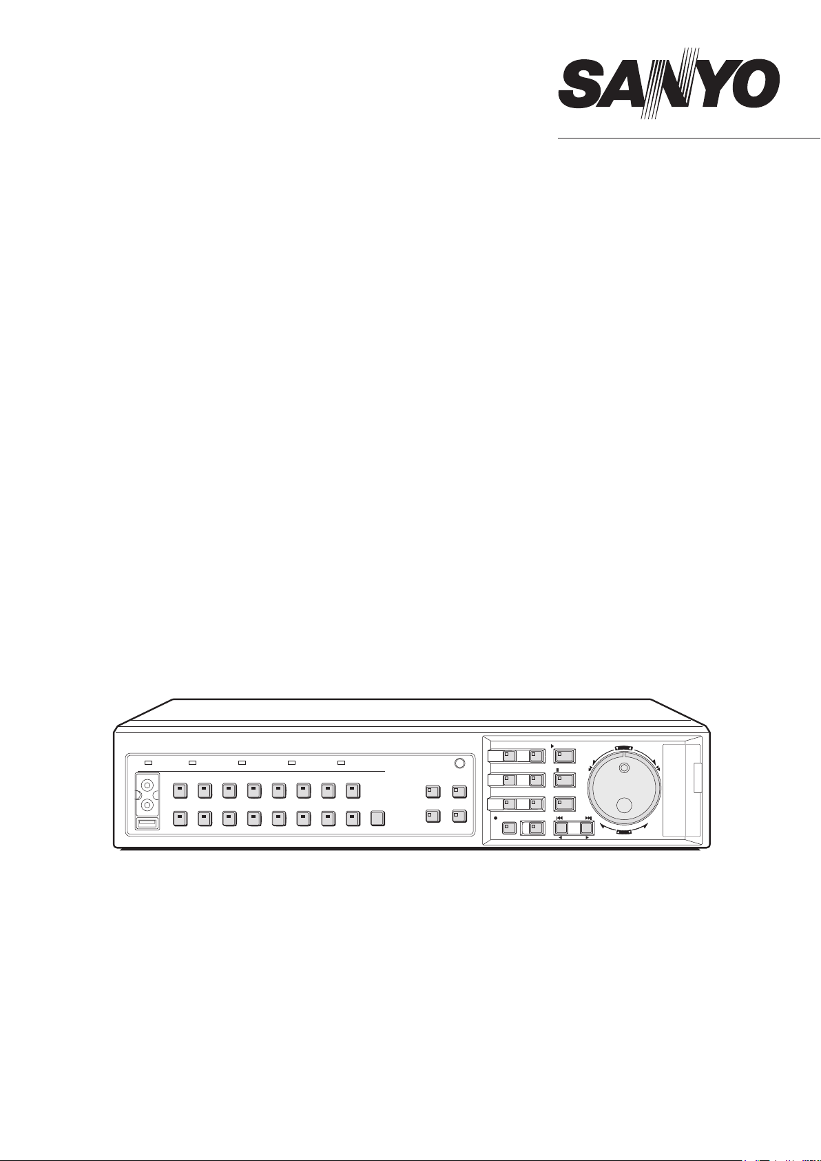
2 NAMES AND FUNCTIONS OF PARTS
DSR-5016P
1 2 3 4 5
POWER FULL ERROR LOCK ALARM
6
7
AUDIO
OUT
VIDEO
USB
45
12 13
678123
14 15
AUDIO
1691011
12 11
13
QUAD
PRESET
SEQUENCE
FUNC.
MULTI
AUTO PAN
PLUSMON 2
TOUR
16 17 18
2019 21
MENU
EXIT/OSD
MENU
ENTER AF
ZOOM
SEARCH
SEQUENCE
COPY
SHUTTLE HOLD
REC/STOP
TIMER
PLAY/STOP
STILL
IRIS
FOCUS
ALARM
ZOOM/I/FO
28
SHUTTLE
JOG
E
N
T
R
A
E
L
C
E
R
MENU
RESET
PAN
EJECT
29
CARDCARD
30
8 10
9
Front panel
1. POWER indicator
Lights up when the power is on.
2. FULL indicator (JP.81)
Flashes when the amount of available memory in the hard
disk’s recording area drops to the percentage specified using
menu settings.
In addition, recording stops automatically when no more
memory is available, and the FULL indicator switches to a
permanently lit condition.
The indicator can then be turned off by performing “AREA
FULL RESET”.
3. ERROR indicator (JP.17)
This indicator flashes if the HDD or fan begins to malfunction.
4. LOCK indicator (JP.113)
Lights up when operations have been locked.
The LOCK indicator turns off when the lock condition is
cancelled.
5. ALARM indicator
Flashes during alarm recording.
The ALARM indicator lights up during pre-alarm recording.
6. AUDIO OUT (RCA) terminal
Connect this terminal and VIDEO OUT terminal to a
commercially-available VCR or DVD recorder to enable
copying of recorded audio and video. (Same as the audio
output terminal on the rear panel)
7. VIDEO OUT (RCA) terminal
Connects to a commercially-available VCR or DVD recorder
to enable copying of recorded video. (Same as the MAIN
MONITOR output terminal on the rear panel)
8. USB terminal (JP.54)
Connects to a recordable CD or DVD drive.
For compatibility, refer to the SANYO homepage.
http://www.sanyosecurity.com/
The rear panel and front panel USB terminals cannot be
connected to simultaneously.
14 15
22
26 27 24
25
23
9. [CAMERA SELECT] buttons and indicators
When one or more cameras have been connected to the
VIDEO IN terminals on the digital video recorder’s rear panel
and the appropriate [CAMERA SELECT] button is pressed,
the corresponding indicator lights up and the video feed from
that camera is displayed on-screen.
z During quad, multi 9, or multi 16 screen display:
The indicators corresponding to the cameras being
displayed on the monitor light up.
z During video loss:
The indicator starts to flash.
z If an alarm occurs:
The indicator for the corresponding camera starts to flash.
10. [AUDIO] button
Audio input channels connected to the rear panel AUDIO IN
terminal can be switched.
Each time this button is pressed, the channel changes in the
following order: 1+2, OFF, 1, 2.
11. [FUNC.] button
Activates dome camera operation mode. The operation of
other buttons changes. (JP.145) Use also for advanced
menu functions.
12. [QUAD] button and indicator (JP.23)
Displays video in quad screens. The indicator lights up while
in quad screen display.
The indicator turns off when using a different screen display
mode.
13. [MULTI] button and indicator (JP.24)
Displays video in multi 9 or multi 16 screen display.
The indicator lights up while in multi 9 or multi 16 screen
display.
The indicator turns off when using a different screen display
mode.
The DSR-5009P can only display video in nine screens.
14. [MON2] button and indicator (JP.26)
If the [MON2] button is pressed while a monitor is connected
to the MON2 output terminal on the rear panel, it is possible to
change the monitor 2 video. The [CAMERA SELECT],
[SEQUENCE], [QUAD], [MULTI] and [PLUS] buttons can be
used. The indicator lights up when this mode is selected.
15. [PLUS] button (JP.24)
Changes the video from a single camera to quad screen size
during multi 9, multi 16, full screen or quad screen display.
For DSR-5009P, this operation is available when in multi 9,
quad and full screen display.
English 9
Page 11

NAMES AND FUNCTIONS OF PARTS2
DSR-5009P
1 2 3 4 5
POWER FULL ERROR LOCK ALARM
6
7
AUDIO
OUT
VIDEO
USB
8 10
16. [MENU] button and indicator
Displays the menu screens (i.e., setting screens), and the
indicator lights up while any of these screens is being
displayed.
17. [EXIT/OSD] button and indicator
z EXIT:
Exits the main menu or a sub-menu. When a menu is
displayed, the indicator turns off.
z OSD:
Each time the [OSD] button is pressed while the digital video
recorder is recording, playing, or stopped, the operation
display area changes position between the top and bottom of
the screen or becomes hidden; furthermore, the indicator
lights up whenever this information is being displayed.
18. [PLAY/STOP] button and indicator (JP.31)
When the [PLAY/STOP] button is pressed, the video from the
recording area is played and the indicator lights up. When
pressed during playback, this button stops the digital video
recorder.
19. [ZOOM] button and indicator (JP.32)
When the [ZOOM] button is pressed during playback or
monitoring of camera video on a full screen, a portion of the
playback video is magnified and the indicator lights.
20. [SEARCH] button and indicator (JP.36)
When the [SEARCH] button is pressed while the digital video
recorder is recording or stopped, the search menu is
displayed and the indicator lights up. Press this button again
to close the search menu.
21. [STILL] button and indicator (JP.33)
When the [STILL] button is pressed during playback, the
current frame is displayed as a still image and the indicator
lights up. Press this button again to cancel.
22. [SEQUENCE] button and indicator (JP.25)
Automatically switches the camera video during monitoring.
When this button is pressed, the indicator begins flashing and
the display is changed automatically. The [CAMERA
SELECT] button indicator lights in accordance with screen
changes.
23. [COPY] button and indicator (JP.50)
Copies recorded video to the HDD’s archive area,
CompactFlash card, Microdrive, CD-R/RW, or DVD+R/+RW.
The indicator lights up during the copy process.
45
9
678 9123
AUDIO
12 11
13
QUAD
PRESET
SEQUENCE
14 15
FUNC.
MULTI
AUTO PAN
PLUSMON 2
TOUR
16 17 18
MENU
MENU
ZOOM
SEQUENCE
REC/STOP
22
25
2019 21
EXIT/OSD
PLAY/STOP
ENTER AF
SEARCH
STILL
IRIS
COPY
SHUTTLE HOLD
FOCUS
ALARM
TIMER
ZOOM/I/FO
23
26 27 24
28
SHUTTLE
JOG
E
N
T
R
A
E
L
C
E
R
CARDCARD
MENU
RESET
PAN
EJECT
24. [SHUTTLE HOLD] button and indicator (JP.31)
Locks shuttle dial operation for a constant speed during
playback or slow playback.
The indicator lights up while the shuttle dial is locked.
25. [REC/STOP] button and indicator (JP.29)
Starts normal recording, and the indicator lights up during this
process.
Press this button for at least three seconds to stop recording
and turn off the indicator.
26. [TIMER] button and indicator (JP.29)
If the [TIMER] button is pressed while the recording is
stopped, timer recording standby mode is selected and
recording starts automatically at the set time. The indicator
lights up while in timer recording standby mode.
If the button is pressed during timer recording, this process is
stopped and the indicator turns off. Furthermore, if the
[TIMER] button is pressed when in timer recording standby
mode, timer recording is cancelled.
27. [ALARM] button (JP.40)
When an [ALARM] button is pressed during playback or still,
the digital video recorder skips to the next earlier or next later
alarm.
28. Jog dial (inside) and shuttle dial (outside)
z During playback:
Use the jog dial to change the playback speed.
Use the shuttle dial to perform fast-forward or fast-reverse
playback.
z During menu display:
Use the jog dial to move the cursor and to change setting
values. Use the shuttle dial to confirm settings.
29. CompactFlash card slot (JP.51)
This slot is used to house a CompactFlash card or Microdrive.
30. [MENU RESET] button (JP.59)
Restores displayed menus to default menu settings.
29
30
INTRODUCTION SETTINGS NETWORK
CONTROL
NETWORK
OPERATION
NETWORK
SETTINGS
OTHEROPERATION
10 English
Page 12
NAMES AND FUNCTIONS OF PARTS2
DSR-5016P
The number of terminals for the DSR-5009P may differ. For more details, see below.
5 6 7 8 9 10
1
SCSI
MONITOR OUT
1
2
2 3 4 5 6 7 8 9 10 11 12 13 14 15 16
IN
3
OUT
ALL
RESET
123 4
EXTERNAL STRAGE UNIT
4
MAIN
MON2 S-VIDEO 1-AUDIO-2
USB
16
LAN
17
AUDIO OUT
RS-485
A SANYO SSP B
MIC IN
IN
RS-485
TERMINATE
OFF ON
DO NOT CONNECT TO PHONE LINE
19
RS-232C
20
ALARM IN
C
SENSOR
ALARM OUT
EXCEPT SANYO SSP
11
123456789
EXT TIMER IN
C
ALARM
LOCK
2ND
CLOCK IN
RS-485/422
REMOTE
OUT
R1 R2
BC
A
CONTROL
10 11 12 13 14 15 16
ARCHIVE FULL
ALARM RESET
WARNING OUT
NO
N RE
FULL
C O
OUT
UT
AC IN
12
21
22
C
13181514
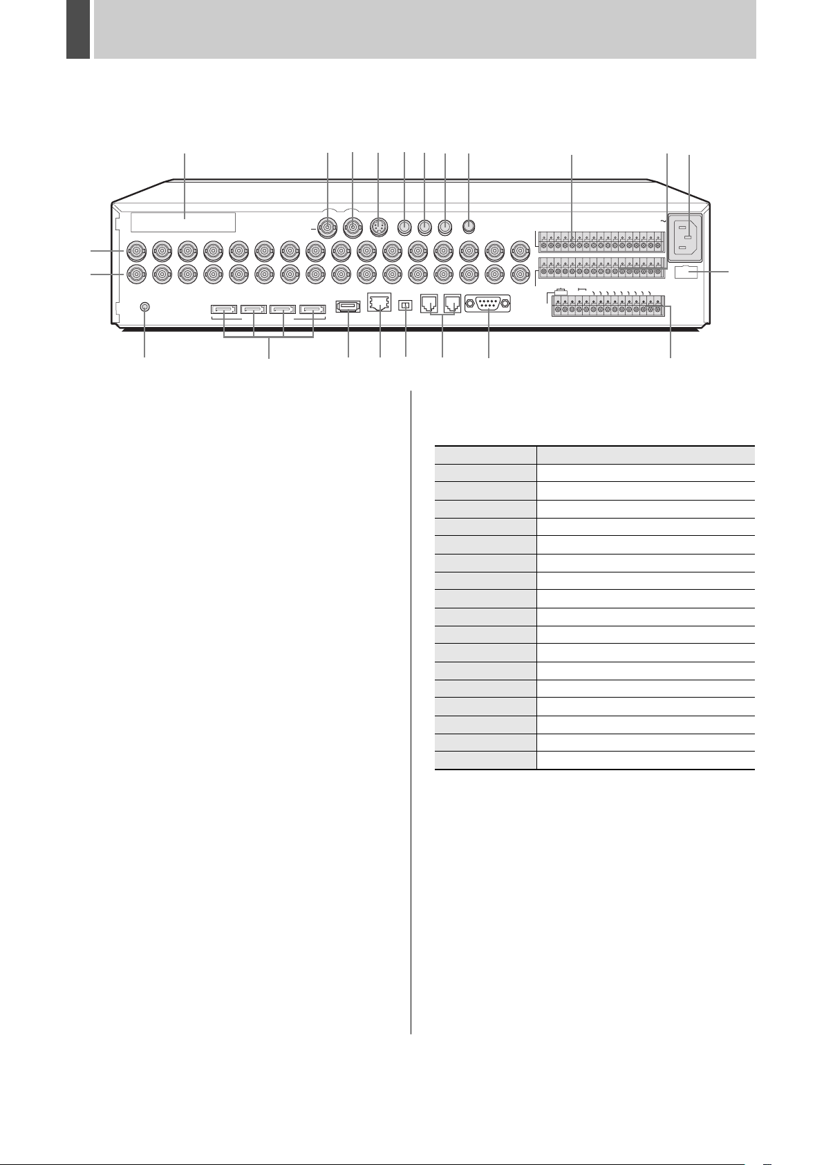
Rear panel
1. SCSI terminal (option board)
Used to add a RAID unit by SCSI connection. Cannot be used
together with an expansion unit. Only a RAID unit can be
used.
Please contact the dealer for details.
When handling and connecting, be sure to read the instruction
manual included with the option board.
2. VIDEO IN terminals
Connects to video cameras.
The DSR-5009P has nine terminals.
3. VIDEO OUT terminals
Connects to a monitor to view camera images.
The DSR-5009P has nine terminals.
4. MAIN MONITOR output terminal
Connects to the main monitor.
5. MON2 output terminal (digital output)
Connects to monitor 2.
6. S-VIDEO output terminal
Connects to a high-quality device.
The same image is output to the main monitor.
7. AUDIO1 IN terminal
Used to connect to an audio amplifier. A microphone or
wireless device can then be connected to the amplifier. Use
with AUDIO2 IN terminal to record and play back audio from
two locations.
8. AUDIO2 IN terminal
Connects to an audio amplifier in the same manner as
AUDIO1 IN terminal.
9. AUDIO OUT terminal
10. MIC IN terminal
Connects to a microphone.
The MIC IN terminal is given priority over the AUDIO1/2 IN
terminal.
11. ALARM IN terminals (1 to 16)
Connects to an externally installed alarm switch. Operate the
alarm switch for alarm recording.
The DSR-5009P has nine terminals.
Pin Signal
C Ground
ALARM IN 1 Alarm input No. 1
ALARM IN 2 Alarm input No. 2
ALARM IN 3 Alarm input No. 3
ALARM IN 4 Alarm input No. 4
ALARM IN 5 Alarm input No. 5
ALARM IN 6 Alarm input No. 6
ALARM IN 7 Alarm input No. 7
ALARM IN 8 Alarm input No. 8
ALARM IN 9 Alarm input No. 9
ALARM IN 10 Alarm input No. 10
ALARM IN 11 Alarm input No. 11
ALARM IN 12 Alarm input No. 12
ALARM IN 13 Alarm input No. 13
ALARM IN 14 Alarm input No. 14
ALARM IN 15 Alarm input No. 15
ALARM IN 16 Alarm input No. 16
English 11
Page 13
NAMES AND FUNCTIONS OF PARTS2
12. SENSOR ALARM OUT terminals
The terminals are used when motion sensors have been set
(JP.99) to output an alarm signal to a connected device upon
detection of motion.
The DSR-5009P has nine terminals.
Pin Signal
C Ground
SENSOR ALARM OUT 1
SENSOR ALARM OUT 2
SENSOR ALARM OUT 3
SENSOR ALARM OUT 4
SENSOR ALARM OUT 5
SENSOR ALARM OUT 6
SENSOR ALARM OUT 7
SENSOR ALARM OUT 8
SENSOR ALARM OUT 9
SENSOR ALARM OUT 10
SENSOR ALARM OUT 11
SENSOR ALARM OUT 12
SENSOR ALARM OUT 13
SENSOR ALARM OUT 14
SENSOR ALARM OUT 15
SENSOR ALARM OUT 16
Output of an alarm signal for
Camera No. 1
Output of an alarm signal for
Camera No. 2
Output of an alarm signal for
Camera No. 3
Output of an alarm signal for
Camera No. 4
Output of an alarm signal for
Camera No. 5
Output of an alarm signal for
Camera No. 6
Output of an alarm signal for
Camera No. 7
Output of an alarm signal for
Camera No. 8
Output of an alarm signal for
Camera No. 9
Output of an alarm signal for
Camera No. 10
Output of an alarm signal for
Camera No. 11
Output of an alarm signal for
Camera No. 12
Output of an alarm signal for
Camera No. 13
Output of an alarm signal for
Camera No. 14
Output of an alarm signal for
Camera No. 15
Output of an alarm signal for
Camera No. 16
13. Control terminals
Pin Signal
2ND RS485/422 A Control terminal (A)
2ND RS485/422 B Control terminal (B)
C Ground
REMOTE R1 Remote input 1
REMOTE R2 Remote input 2
CLOCK IN Clock adjust input terminal
CLOCK OUT Clock adjust output terminal
EXT TIMER IN External timer input terminal
ALARM OUT Alarm output terminal
ALARM RESET Cancels alarm
NON REC OUT Non-recording output
WARNING OUT HDD or FAN error warning output
FULL
ARCHIVE FULL
C Ground
Capacity warning output for
recording area
Capacity warning output for archive
area
14. [ALL RESET] button
When the [ALL RESET] button is pressed, the digital video
recorder is reset and the time is returned to its default setting.
15. Expansion unit connection terminal
Used to expand the hard disk. Cannot be used together with
RAID unit.
Please contact the dealer for details. When handling and
connecting, be sure to read the instruction manual included
wtih the external storage unit.
16. USB terminal
Connects to a recordable CD or DVD drive. For compatibility,
refer to the SANYO homepage.
http://www.sanyosecurity.com/
The rear panel and front panel USB terminals cannot be
connected to simultaneously.
17. LAN terminal (10BASE-T/100BASE-TX)
Connect to switching hubs, routers and PCs.
18. RS-485 termination switch
Used when connecting multiple devices from the RS-485
control connectors.
19. RS-485 control connectors (A) (B)
Connects to a system controller or dome cameras.
20. RS-232C terminal
Connects to a modem.
21. AC power socket (AC IN)
Insert the supplied power cord securely into this socket.
22. Power cord holder
Secure the power card to the holder using the power cord tie
(accessory) as shown in the illustration.
INTRODUCTION SETTINGS NETWORK
CONTROL
NETWORK
OPERATION
NETWORK
SETTINGS
12 English
OTHEROPERATION
Page 14
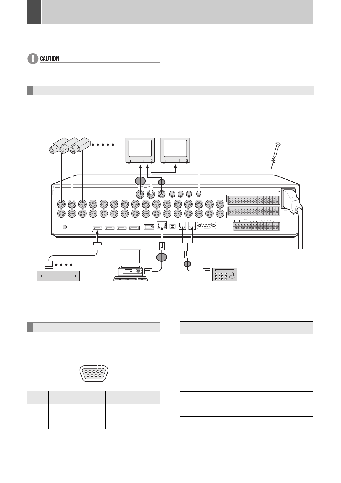
3 INSTALLATION AND CONNECTIONS
This section describes how to connect the digital video recorder to video cameras and other devices. Be sure to read the instruction
manuals for each connected device.
z Improper connections may result in malfunction or smoke emission.
z A separate power supply is required for operation of each camera.
z Manage power for all expansion units with a single power source. Otherwise, data may be lost.
Basic connections
DSR-5016P
Only nine cameras can be connected to the DSR-5009P.
The following diagram shows the connections for cameras, monitors, a microphone, a PC and a system controller.
Cameras
(sold separately)
1 - 16
Monitor
(sold separately)
Video input
terminal
(sold separately)
0201
0403
Monitor 2
Video input
terminal
* If monitor 2 is not synchronized
with the connected cameras,
vertical picture instability may
occur upon the switching of
camera video.
Microphone
(commerciallyavailable)
*3
MON2 S-VIDEO 1-AUDIO-2
SCSI
MONITOR OUT
1
2 3 4 5 6 7 8 9 10 11 12 13 14 15 16
IN
OUT
ALL
RESET
1234
EXTERNAL STRAGE UNIT
MAIN
USB
*4
AUDIO OUT
RS-485
A SANYO SSP B
MIC IN
RS-232C
IN
LAN
RS-485
TERMINATE
OFF ON
DO NOT CONNECT TO PHONE LINE
The RS-485 connector is
connected to A or B according to
the type of cable.
*2
System controller
(sold separately)
1 - 4
HDD expansion unit
(sold separately)
*1
PC
(commercially-available)
*1 Wrap the LAN cable once around the core clamp (large) before attaching it.
*2 Wrap the RS-485 cable twice around the core clamp (small) before attaching it.
*3 Wrap the Main Monitor output cable once around the core clamp (large) before attaching it.
*4 Wrap the S-VIDEO output cable once around the core clamp (small) before attaching it.
Connecting the RS-232C terminal
The RS-232C terminal is used to connect to a PC or a phone
line for use with a modem. Perform the settings in the <RS-
Pin
number
Signal Operation Signal direction
3 TXD Transmit Data
232C/RS-485 SET> screen. (JP.115)
RS-232C Pin locations
54321
4DTR –
5 GND Ground –
6DSR –
Pin
number
Signal Operation Signal direction
1 DCD Carrier Detect
2 RXD Receive Data
9876
From PC to digital video
recorder
From PC to digital video
recorder
7RTS
8 CTS Clear to Send
9 RI Ring Indicator
ALARM IN
C
SENSOR
ALARM OUT
EXCEPT SANYO SSP
Request to
Send
123456789
EXT TIMER IN
C
ALAR
L
2ND
C
OCK OUT
L
OCK IN
REMOTE
RS-485/422
CR1R2
A
B
CONTROL
AC IN
10 11 12 13 14 15 16
AR
ALARM
W
NON RE
ARNING O
CHIVE
RESET
F
M
C
FULL
ULL
OUT
O
UT
UT
C
120 V – 240 V AC
(50/60 Hz)
From digital video
recorder to PC
From digital video
recorder to PC
From PC to digital video
recorder
From digital video
recorder to PC
From PC to digital video
recorder
From PC to digital video
recorder
English 13
Page 15
INSTALLATION AND CONNECTIONS3
INATE
ON
R
DO NOT CONNECT TO PHONE LINE
PPP (dial-up) connection
Make the following connections to use a phone line to connect
to an Internet service provider.
RS-232C
Serial cable
Modem
Internet
Connecting RS-485 control terminals
A system controller or another DVR can be connected to the
RS-485 control terminal. Perform settings in the <RS-232C/
RS-485 SET> screen (JP.115) when connecting system
controller.
Control a connected SANYO camera with an RS-485 control
terminal using a system controller or the digital video recorder
itself. To control a camera equipped with an RS-485 control
terminal, perform settings in the <CAMERA CONTROL SET>
screen (JP.145).
\
System controller
RJ-11 Pin locations
16
z Do not connect to phone line.
Pin
number
1 Not used Not used
2 Not used Not used
3A B
4B A
5 Not used Not used
6 Not used Not used
Connector A signal Connector B signal
A: Non-inverting driver output/receiver input
B: lnverting driver output/receiver input
Connection
The digital video recorder supports both straight type and
crossed type connection cables.
When using a straight type connection cable, connect the RS485 connector pin A to the pin A socket, or pin B to the pin B
socket.
When using a crossed type connection cable, connect the RS485 connector pin A to the pin B socket, or pin B to the pin A
socket.
RS-485
A SANYO SSP B
INTRODUCTION SETTINGS NETWORK
CONTROL
NETWORK
OPERATION
1
2
IN
OUT
z Connect as shown above and set to full screen in the
<CAMERA CONTROL SET> screen to control camera with
the digital video recorder.
z Control a camera by directly entering the camera address
with the system controller regardless of the <CAMERA
CONTROL SET> screen settings when the cameras and
the system controller are connected as shown above.
To other
connector A
To other
connector A
Straight type cable Crossed type cable
Cable types
Straight type: Crossed type:
1
2
3
4
5
6
Not used
Not used
Not used
Not used
1
2
3
4
5
6
z Perform settings in the <RS-232C/RS-485 SET> screen
when a system controller is connected (JP.115).
1
2
3
4
5
6
Not used
Not used
Not used
Not used
1
2
3
4
5
6
NETWORK
SETTINGS
OTHEROPERATION
14 English
Page 16
INSTALLATION AND CONNECTIONS3
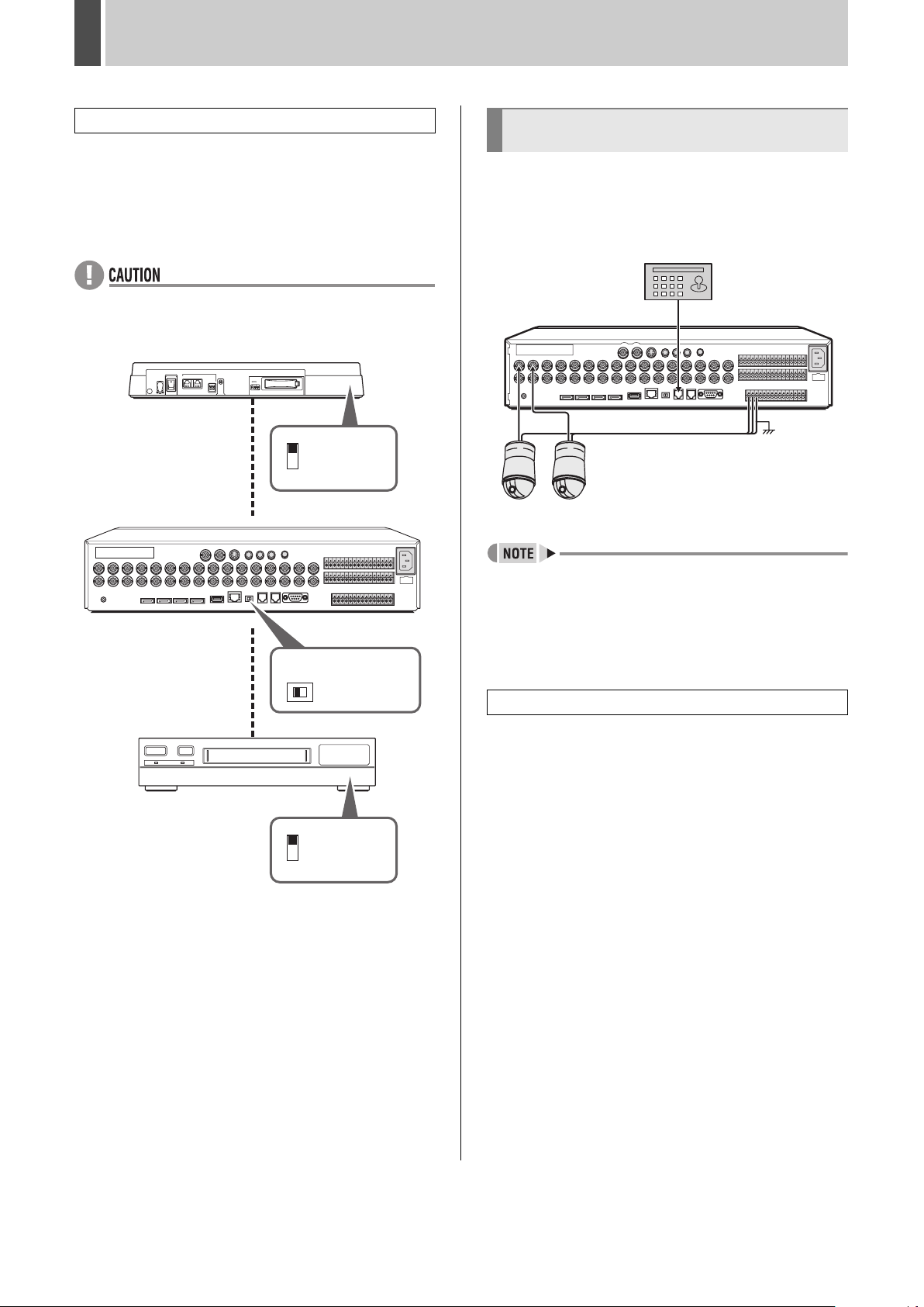
RS-485 termination switch settings
When connecting multiple devices, it is necessary to make
termination settings on both end devices.
z Set the RS-485 termination switch of both end devices to
ON.
z Be sure to set the RS-485 termination switches of all
devices in between (devices other than the first and last
devices) to OFF.
z If the termination settings are not correctly made, the
incorrect data is transmitted to each device.
Example:
System controller
ON
Termination
switch
OFF
Connecting to a 2ND RS485/422
terminal
Connect camera to the 2ND RS485/422 terminal with a
twisted-pair cable and perform settings in the <CAMERA
CONTROL SET> screen (JP.145) to control the camera with
the connected system controller or with the digital video
recorder.
System controller
1
2
IN
OUT
Other companies’ cameras
Digital video recorder
RS-485
TERMINATE
OFF ON
RS-485
TERMINATE
OFF
Time Lapse VCR
ON
OFF
RS485
Termination
ON
switch
Termination
switch
z Connect as shown above and set to full screen in the
<CAMERA CONTROL SET> screen to control camera with
the digital video recorder.
z If connected as shown above, settings must be made in
<CAMERA CONTROL SET> screen.
z Connect other companies’ cameras to the 2ND RS-485/
422 terminals.
Operation
1 Connect as above.
Connect SSP dome cameras to VIDEO IN 1 and 2.
2 Set the camera numbers and protocols
in the <CAMERA CONTROL SET>
screen. (JP.145)
3 Operate the dome cameras with the
front panel buttons. (JP.147)
English 15
Page 17
INSTALLATION AND CONNECTIONS3
Connecting a LAN terminal
Connect to a PC for control of the digital video recorder over a
network with a switch or connect to the Internet.
LAN connection
To enable control of the digital video recorder over a network,
connect to the switch via Ethernet cable or make a similar
connection.
Use a straight type Ethernet cable.
PC
LAN
Ethernet cable
(straight type cable)
Switch
Internet connection
Connect to the Internet via a router or similar device.
When connecting to a router, use a straight type Ethernet
cable.
To connect to an ADSL modem and other devices, be sure to
read the instruction manuals for each connected device.
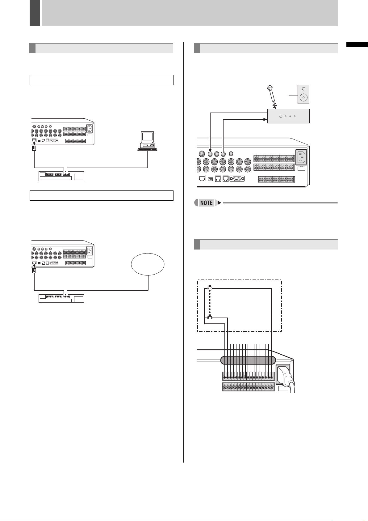
Connecting an amplifier
Connect an amplifier to use a microphone or external
speakers with the digital video recorder. AUDIO 1 IN terminal
and AUDIO 2 IN terminal can be used together to record and
play back audio from two locations.
Audio input
terminal
Audio
output terminal
1-AUDIO-2
AUDIO OUT
IN
z The input audio channel connected to the AUDIO IN
terminal on the rear panel can be switched with the
[AUDIO] button. Each time this button is pressed, the
channel changes in the following order: 1+2, OFF, 1, 2.
Amplifier
(sold separately)
INTRODUCTION SETTINGS NETWORK
CONTROL
Connecting alarm input terminals
LAN
Ethernet cable
(straight type cable)
Router, ADSL
modem, etc.
Internet
When using external alarms (i.e., intruder sensors), connect
external switches to the ALARM IN terminals.
16
Connect external
1
Only terminals 1 to 9 are available on the DSR-5009P.
* Wrap the Alarm input cable and the Sensor alarm output
cable once around the core clamp (large) before attaching it.
switches to ALARM IN
terminals.
*
NETWORK
OPERATION
NETWORK
SETTINGS
OTHEROPERATION
16 English
Page 18
INSTALLATION AND CONNECTIONS3
Connecting SENSOR ALARM OUT
terminals
The SENSOR ALARM OUT terminals are used to relay alarm
signals whenever one of the digital video recorder’s motion
sensors is triggered. Normally in an open condition, a terminal
adopts a low condition when a sensor for the corresponding
camera number has been triggered.
1
Rated value of terminals
z Maximum current: 25 mA
z Maximum voltage: 25 V
Connecting control terminals
The connections for a remote control circuit are shown below.
This digital video recorder can be remotely controlled when a
remote-control circuit similar to that shown here is connected
to the remote-input control terminals.
REMOTE
CR1R2
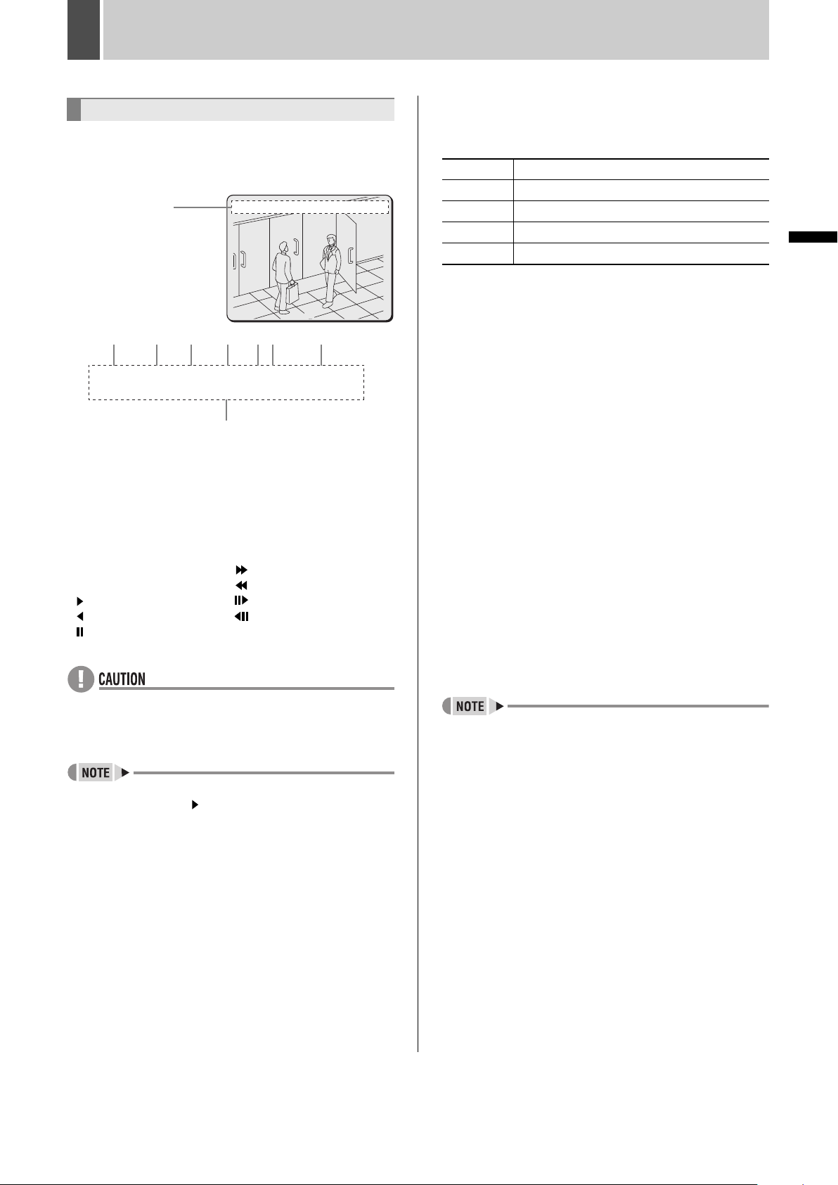
Connecting the power cord
1 After all other connections are made,
make sure the voltage is 120 V-240 V AC
and then insert the power plug into the
wall outlet.
There is no power switch. The display indicators flash, and
after a few moments, the monitor screen displays the camera
video.
120 V-240 V AC
(50/60 Hz)
*
z When turning the power on for the first time
“PLEASE SET THE CLOCK” is displayed on the monitor
screen. Set the clock. (JP.20)
z If the clock is already set
The operation display area is displayed.
Operation
display area
* Attach the core clamp
(large) to the power cord.
01-01-05 00:00:00 EN A
0
R1 R2
(When operated
independently)
SW 1
SW 2
SW 3
SW 4
SW 5
SW 6
SW 7
SW 8
SW 9
SW 10
SW 11
SW 12
SW 13
SW 14
SW 15
SW 16
(When combined
with R2 FUNC key)
:
Camera 1:
INDEX+
Camera 2
:
:
:Camera 4 :Automatic selection display
:
:
:
:
:
:
:
:
:
:
:
:
:INDEX-
Camera 3
:AUTO FOCUS
Camera 5:
Monitor2
Camera 6:
Plus display
Camera 7
:QUAD
Camera 8
:MULTI
Camera 9
:MENU RESET
Camera 10:Not used
Camera 11:PAN left
Camera 12:PAN right
Camera 13:TILT down
Camera 14:TILT up
Camera 15
Camera 16:ZOOM tele
:ZOOM wide
:REC/STOP
SW 17
:PLAY/STOP
SW 18
:STILL
SW 19
:SEARCH
SW 20
SHIFT (Doubles with R1)
:
SW 21
:PLAY
SW 22
:REC
SW 23
:MENU
SW 24
:MENU EXIT(EXIT)
SW 25
: +
SW 26
SW 27
: -
SW 28
: +
SW 29
: -
SW 30
:ZOOM
SW 31
:COPY
SW 32
:TIMER
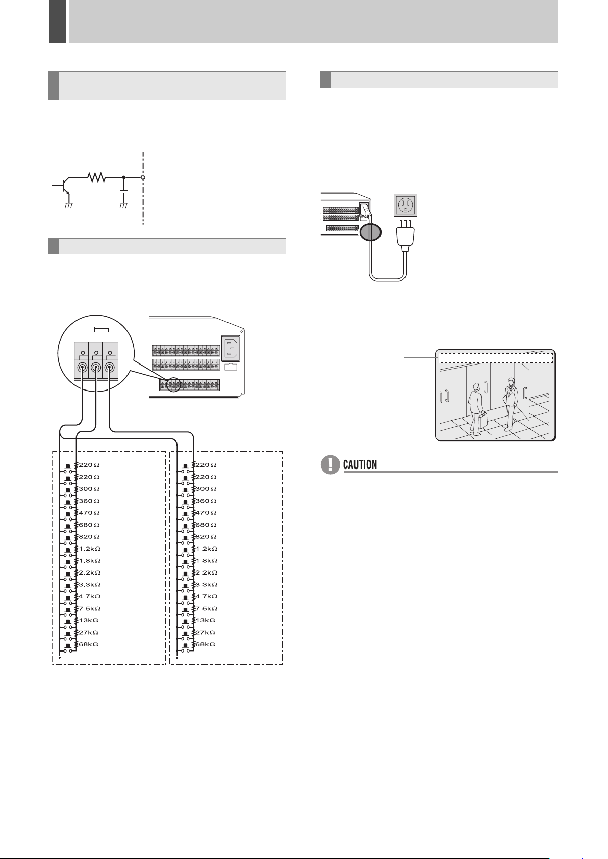
z Use a resistance of 1/10 ohms or more and with a D
ranking (Precision within ±0.5%).
z The remote control cable should be no more than 5 m long.
* The DSR-5009P can operate up to nine cameras.
02
z If the ERROR indicator starts flashing
The digital video recorder has a self-diagnostic function to
find malfunctions. If a malfunction occurs while the power
is on, the ERROR indicator flashes in a cycle to indicate
the malfunction.
If the ERROR indicator flashes, contact a Sanyo service
center.
When flashing at 4Hz (Four times per second):
The hard disk is checked automatically when the power is
turned on. The POWER indicator flashing indicates that a
malfunction has been found on the hard disk and the hard
disk must be replaced or initialized. If you need to save
video stored on the disk, contact a Sanyo service center.
When flashing at 1Hz (Once per second):
A fan malfunction has occurred.
z The power cord’s ground terminal is not provided for
enhanced safety; rather, it is used to reduce the level of
interference when the digital video recorder is connected to
analog devices.
If a large amount of noise is generated when the digital
video recorder is connected to analog devices, connect
this terminal to the building earth ground.
English 17
Page 19
1 PREPARING FOR USE
Operation display
When the power is turned on, the operation display is shown
at the top of the monitor screen. This area indicates the date,
time, picture quality and other information needed for
operation.
Operation
display area
(1) (2) (3) (4) (5)(6) (7)
01-01-05 00:00:00 REC REPEAT EN A ALARM 0000000
02
01-01-05 00:00:00 REC REPEAT EN A ALARM 0000000
02
(8)
* The above is an example display. This is not the default.
(1) Date display (JP.20)
Be sure to specify the correct date using menu settings.
(2) Time display (JP.20)
Make sure to specify the time using menu settings. Recording
is not possible until the time is set.
(3) Operation symbol display
Displays the current operation, such as recording or playback.
REC: Recording : Fast-forward playback
EXT: External timer recording : Fast-rewind playback
: Normal playback : Slow playback
: Reverse playback : Reverse slow playback
: Still
0
(5) Picture quality display (JP.83, P.94)
Displays the quality of the video that can be recorded on the
hard disk. Set to “EN” (Enhanced) by default setting.
[Settings] ( indicates default setting)
BA Basic
NO Normal
EN Enhanced
FI Fine
SF Super Fine
(6) Audio recording display
“A” is displayed when audio is being recorded. “A” is displayed
when audio is being played back if audio is recorded. When
the [AUDIO] button is pressed, the audio channel (OFF/A1/
A2/A12) is displayed.
(7) Alarm display and alarm count display (JP.93)
When an alarm is set using the “ALARM REC MODE SET”
menu item, the following information is displayed.
z When alarm recording is set;
“ALARM” and the alarm number are displayed in stand-by
mode.
“ALARM” flashes during alarm recording.
z When pre-alarm recording is in progress;
“PRE” and the alarm number are displayed in stand-by
mode.
When an alarm occurs, “PRE” disappears and “ALARM”
and the alarm number are displayed.
z When performing playback from the archive area;
“ARCHIV” and the backup number are displayed.
(8) Camera title display
The camera number or camera title is displayed. Also, when
an alarm occurs the camera number and alarm “EA”, “SA”, or
“ES” are displayed.
z When an external alarm signal is activated;
“EA” flashes to the left of the camera number.
z When a motion sensor alarm signal is activated;
“SA” flashes to the left of the camera number.
z When an external alarm signal and motion sensor signal
are activated;
“ES” flashes to the left of the camera number.
INTRODUCTION SETTINGS NETWORK
CONTROL
NETWORK
OPERATION
z The digital video recorder uses the date and time to
manage recording and playback points. Accordingly, if the
time has not been set correctly, it is not possible to
effectively search for video data.
z During simultaneous recording and playback, the display
indicates playback ( ).
(4) Remaining memory in recording area (JP.80)
It is displayed while recording.
Displays the remaining area memory as a percentage when
overwriting in the recording area is not permitted. If
overwriting is permitted, “REPEAT” is displayed.
z Although operations such as playback, copying and data
transfer are possible while recording, this unit gives priority
to recording, and other operations may be delayed as a
result.
NETWORK
SETTINGS
OTHEROPERATION
18 English
Page 20
PREPARING FOR USE1
[MENU] button
[EXIT/OSD] button
Changing the display position of the
operation display area
1 Press the [EXIT/OSD] button.
EXIT/OSD
Each time the [EXIT/OSD] button is pressed, the operation
display moves to a different location or is hidden.
Top (default setting)
Bottom
Hidden
Operation
Operation
display area
display area
01-01-05 00:00:00 EN A1
01 02
01-01-05 00:00:00 EN A1
03 04
Changing the language
The language displayed on the monitor can be changed.
[Settings] ( indicates default setting)
Item Setting Description
ENGLISH Sets the language to English.
LANGUAGE
FRANCAIS Sets the language to French.
DEUTSCH Sets the language to German.
ESPAÑOL Sets the language to Spanish.
1 Press the [MENU] button.
The MENU indicator lights up and the <MAIN MENU> is
displayed.
MENU
<MAIN MENU>
1.INITIAL SET ->
2.RECORD SET ->
3.GENERAL SET ->
4.SCREEN SET ->
5.POWER LOSS/USED TIME ->
6.INITIALIZATION LOG ->
7.COPY MENU SETTINGS ->
8.ADVANCED MENU SET ->
MOVE:JOG SELECT:SHUTTLE
2 Turn the jog dial to select “1.INITIAL
SET” and then turn the shuttle dial
clockwise.
The <INITIAL SET> screen is displayed.
English 19
<INITIAL SET>
1.LANGUAGE/CLOCK SET ->
2.CAMERA DETECT ->
3.TITLE SET ->
4.HOLIDAY SET ->
5.TIME PERIOD SET ->
MOVE:JOG SELECT:SHUTTLE
Page 21
PREPARING FOR USE1
3 Turn the jog dial to select
“1.LANGUAGE/CLOCK SET” and then
turn the shuttle dial clockwise.
The <LANGUAGE/LANGUE/SPRACHE/IDIOMA> screen is
displayed.
<LANGUAGE/LANGUE/SPRACHE/IDIOMA>
ENGLISH
<CLOCK SET>
01-01-2005 SAT 00:00:00
<SUMMER TIME SET>
MODE : USE
WEEK MONTH TIME
ON LST-SUN 03 02:00
OFF LST-SUN 10 02:00
<EXT.CLOCK SET>
ADJUST. TIME 01:00
4 Turn the shuttle dial clockwise.
“ENGLISH” flashes.
<LANGUAGE/LANGUE/SPRACHE/IDIOMA>
ENGLISH
<CLOCK SET>
01-01-2005 SAT 00:00:00
<SUMMER TIME SET>
MODE : USE
WEEK MONTH TIME
ON LST-SUN 03 02:00
OFF LST-SUN 10 02:00
<EXT.CLOCK SET>
ADJUST. TIME 01:00
5 Turn the jog dial to select the language
and then turn the shuttle dial clockwise.
The language is selected and the cursor moves to the next
item.
Setting the time
(Default setting: 01-01-2005 SAT 00:00:00)
Be sure to set the correct date and time as these settings are
used during playback and searching.
Example: Setting 8:30 on 26 October, 2005.
1 Press the [MENU] button.
The MENU indicator lights up and the <MAIN MENU> is
displayed.
MENU
<MAIN MENU>
1.INITIAL SET ->
2.RECORD SET ->
3.GENERAL SET ->
4.SCREEN SET ->
5.POWER LOSS/USED TIME ->
6.INITIALIZATION LOG ->
7.COPY MENU SETTINGS ->
8.ADVANCED MENU SET ->
MOVE:JOG SELECT:SHUTTLE
2 Turn the jog dial to select “1.INITIAL
SET” and then turn the shuttle dial
clockwise.
The <INITIAL SET> screen is displayed.
<INITIAL SET>
1.LANGUAGE/CLOCK SET ->
2.CAMERA DETECT ->
3.TITLE SET ->
4.HOLIDAY SET ->
5.TIME PERIOD SET ->
INTRODUCTION SETTINGS NETWORK
CONTROL
<REGL.LANGUE>
FRANCAIS
<REGL.HORLOGE>
01-01-2005 SAM 00:00:00
<HEURE D^ETE>
MODE : MARCHE
SEMAINE MOIS HEURE
ON DER-DIM 03 02:00
OFF DER-DIM 10 02:00
<REGL.HORLOGE EXTERNE>
REGL.DE L^HEURE 01:00
6 Press the [EXIT/OSD] button.
The setting is completed and the display returns to the normal
screen.
EXIT/OSD
MOVE:JOG SELECT:SHUTTLE
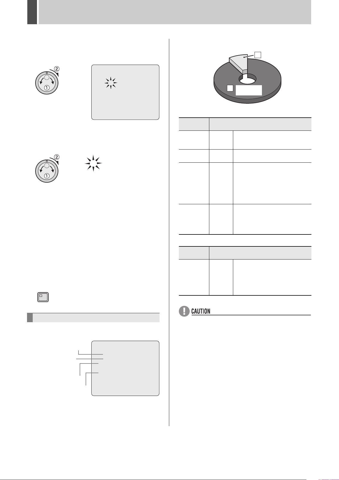
3 Turn the jog dial to select
“1.LANGUAGE/CLOCK SET” and then
turn the shuttle dial clockwise.
The <LANGUAGE/LANGUE/SPRACHE/IDIOMA> screen is
displayed.
<LANGUAGE/LANGUE/SPRACHE/IDIOMA>
ENGLISH
<CLOCK SET>
01-01-2005 SAT 00:00:00
<SUMMER TIME SET>
MODE : USE
WEEK MONTH TIME
ON LST-SUN 03 02:00
OFF LST-SUN 10 02:00
<EXT.CLOCK SET>
ADJUST. TIME 01:00
NETWORK
OPERATION
NETWORK
SETTINGS
OTHEROPERATION
20 English
Page 22
PREPARING FOR USE1
80%
20
4 Turn the jog dial to select “01” and then
turn the shuttle dial clockwise.
“01” flashes (indicating the day).
<LANGUAGE/LANGUE/SPRACHE/IDIOMA> [KEY]
ENGLISH
<CLOCK SET>
01-01-2005 SAT 00:00:00
<SUMMER TIME SET>
MODE : USE
WEEK MONTH TIME
ON LST-SUN 03 02:00
OFF LST-SUN 10 02:00
<EXT.CLOCK SET>
ADJUST. TIME 01:00
5 Turn the jog dial to select “26” and then
turn the shuttle dial clockwise.
The day is set to “26” and the month “01” flashes.
26-01-2005 WED 00:00:00
6 Use the same procedure to set the
month (10), year (2005), hour (08) and
minute (30).
When the minutes are set, the cursor moves to the next item.
26-10-2005 WED 08:30:00
z The day of the week is set automatically.
z The clock stops during date and time settings.
z The clock starts counting from 00 seconds.
7 Press the [EXIT/OSD] button.
The setting is completed and the display returns to the normal
screen.
EXIT/OSD
Hard disk recording areas
20
20%
Recording
A
area
[A] Recording area
Recording
mode
Normal
recording
Timer
recording
Alarm
recording
Pre-alarm
recording
Manual
Automatic
Automatic
Automatic
Recording method
When monitoring, recording is
performed by pressing the [REC/
STOP] button.
Recording is carried out in
accordance with timer settings.
Recording is carried out when alarm
recording is set to “ENABLED”.
Alarm images are recorded in
response to either the operation of a
switch connected to an ALARM IN
terminal or to the detection of an
intruder via motion sensors.
When pre-alarm recording is set to
“ON”, it is possible to record video
from before the occurrence of an
alarm based on the corresponding
settings.
[B] Archive area
Recording
mode
Copy
Manual
or
Automatic
Recording method
This area is used to store important
video data copied from the normal
recording area and/or alarm
recording area. Changes can be
made to the recording area to
determine the capacity. (1% - 99% )
Archive area
B
80%
80%
Hard disk archive area
The hard disk contains a recording area and an archive area.
Refer to P.77 for operations.
Hard disk recorder internal
hard disk capacity display
Hard disk recorder
external hard disk
capacity display
[A] Recording area
[B] Archive area
English 21
<RECORDING AREA SET>
TOTAL CAPACITY : 1500GB
INTERNAL HDD : 500GB
EXTERNAL HDD : 1000GB
RECORDING AREA : 80 %
AREA FULL RESET ->
ARCHIVE AREA : 20 %
AREA FULL RESET ->
CAUTION: WHEN THE AREA SETTING IS CHANGED,
THE WHOLE AREA WILL BE INITIALIZED !
z If the memory allocations for the hard disk recording areas
are changed after recording, all stored recordings are
deleted and the hard disk is initialized; accordingly, special
care should be taken. (JP.77)
z The total hard disk capacity displayed on the menu screen
may differ from the actual hard disk capacity.
Page 23
2 MONITORING VIDEO FROM A CAMERA
[MULTI] button
[CAMERA SELECT] button
Viewing on a full screen
Example: Selecting Camera 2
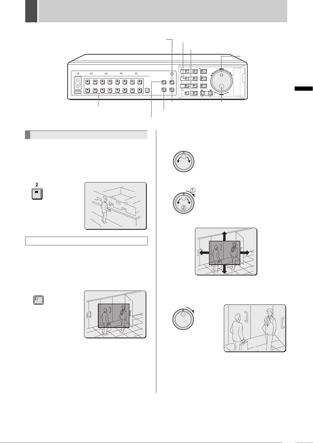
1 Press the No. 2 [CAMERA SELECT]
button.
The CAMERA SELECT indicator lights up and video from
Camera 2 is displayed on a full screen.
[MON2] button
[QUAD] button
2 Move the zoom frame to the area to be
z Turn the jog dial to move the zoom frame to the left or right.
z Turn the shuttle dial clockwise and then turn the jog dial to
[ZOOM] button
[SEQUENCE] button
[PLUS] button
Jog dial
magnified.
move the zoom frame vertically.
INTRODUCTION SETTINGS NETWORK
Shuttle dial
02
Viewing enlarged live images
1 Press the [ZOOM] button during
monitoring of camera video.
Press the button corresponding to the camera for which video
is being magnified.
The ZOOM indicator lights up and a blue zoom frame appears
in the center of the screen.
ZOOM
Move the zoom frame to the area to be magnified.
3 Turn the shuttle dial clockwise.
The area enclosed by the zoom frame is magnified (by a
factor of 2).
02
CONTROL
NETWORK
OPERATION
NETWORK
SETTINGS
OTHEROPERATION
22 English
Page 24
MONITORING VIDEO FROM A CAMERA2
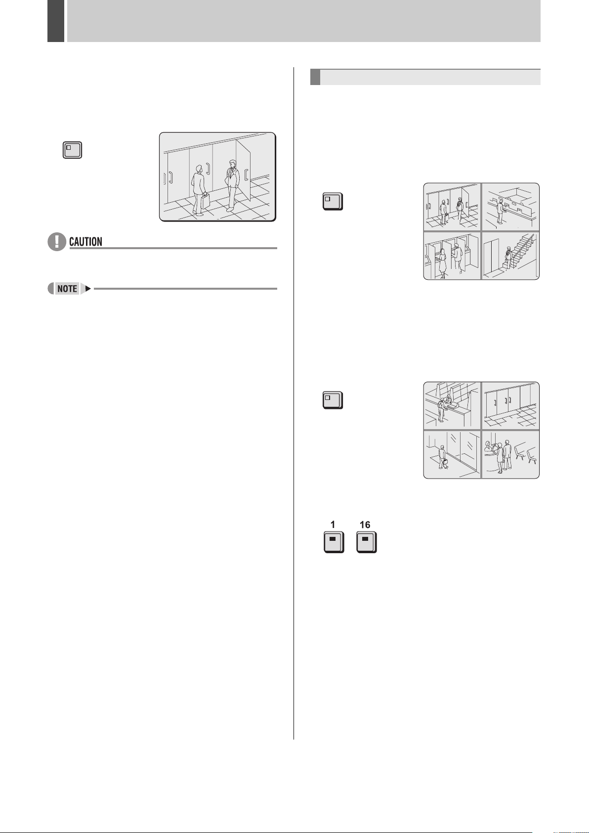
4 Press the [ZOOM] button to return to
normal magnification.
Magnification is cancelled and the display returns to the
normal screen.
The ZOOM indicator turns off.
ZOOM
02
z Magnified video has a slightly coarser appearance when
compared with normal video.
z Images cannot be enlarged in multi-screen format.
Viewing on quad screens
Images from multiple connected cameras can be displayed
simultaneously.
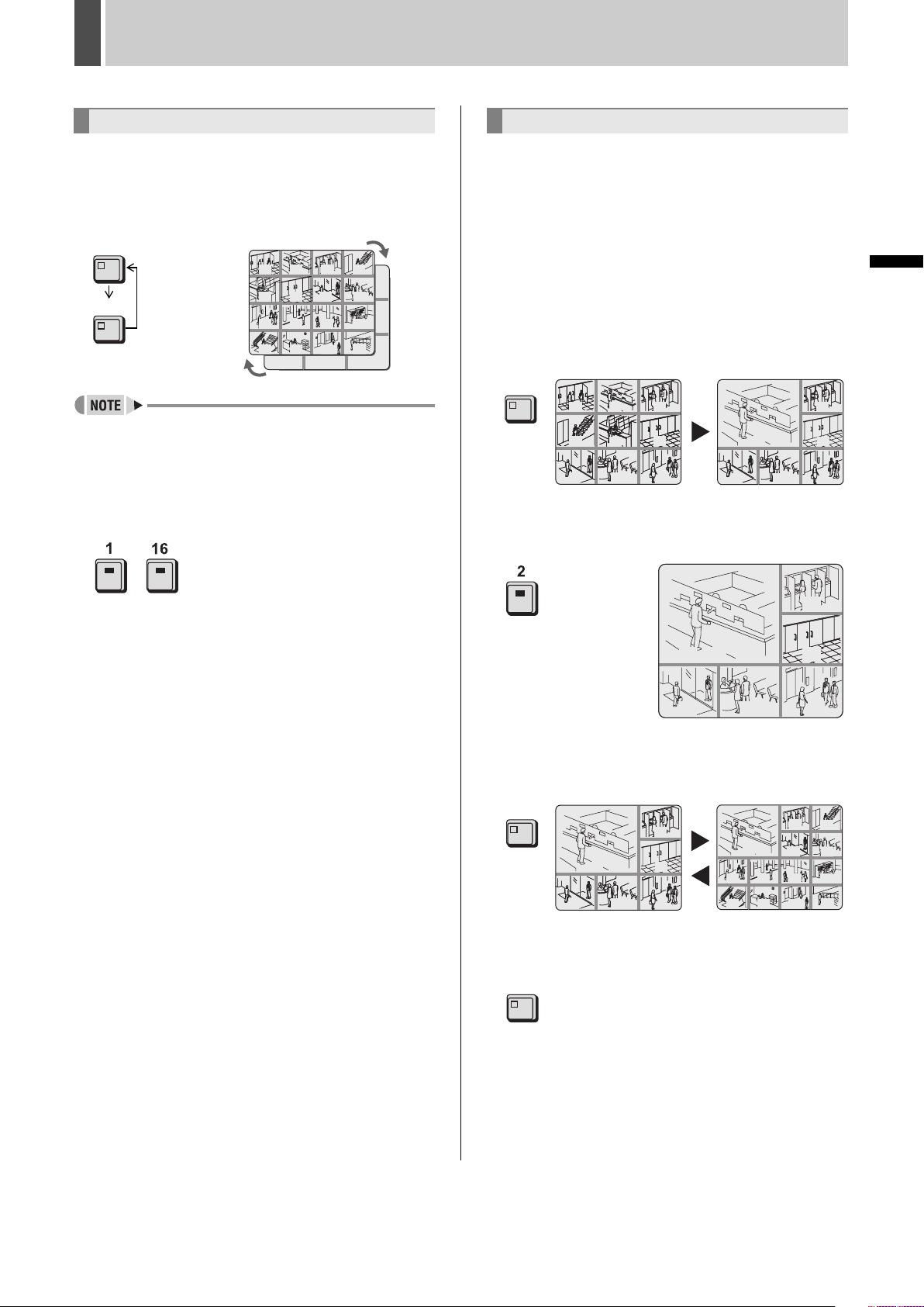
1 Press the [QUAD] button.
The QUAD indicator lights up and video from four separate
cameras is displayed simultaneously.
Video from Camera No. 1 through Camera No. 4 is initially
displayed.
QUAD
0201
0403
2 To view video from other cameras,
press the [QUAD] button again.
Each time this button is pressed, the four images on the quad
screen change, in order of cameras No. 1-4, 5-8, 9-12 and 1316 (default setting).
On the DSR-5009P, the images change in order of cameras
No. 1-4, 5-8, 9-3, etc.
QUAD
0605
0807
3 To return to full screen display, press a
[CAMERA SELECT] button.
-
On the DSR-5009P, press the [CAMERA SELECT] 1-9
button.
English 23
Page 25
MONITORING VIDEO FROM A CAMERA2
Viewing on multi 9 or multi 16 screens
1 Press the [MULTI] button.
The MULTI indicator lights up and video from 16 separate
cameras is displayed simultaneously. Press the [MULTI]
button again to display multi 9 screens.
The DSR-5009P can only display video from nine cameras.
MULTI
03
02
MULTI
01
01
05 06
04
09 11 12
10
13 14 15
07 08 09
04
0302
08
07
06
05
16
z In the case of both quad and multi 9/16 screen display, you
can change the positions in which video from the various
cameras is displayed. (JP.126)
2 To return to full screen display, press a
[CAMERA SELECT] button.
-
On the DSR-5009P, press the [CAMERA SELECT] 1-9
button.
Enlarging video
Enlarges the video from a single camera to quad screen size
during multi 9 or multi 16 screen display. (enlarged video)
In addition, video can also be enlarged during full screen and
quad screen displays.
For DSR-5009P, this operation is available when in multi 9,
quad and full screen display.
Example: Enlarging video during multi 9 screen display
1 Press the [PLUS] button during multi 9
screen display.
The PLUS indicator lights up and the video from one camera
is enlarged.
PLUS
01
01
04
04
0707 090808
0302
0302
06
06
05
05
09
02
0707
0303
03
06
0808
09
2 Press a [CAMERA SELECT] button.
The video from the selected camera is enlarged.
01
0302
03
INTRODUCTION SETTINGS NETWORK
CONTROL
04
02
05
07 08 09
07 08 09
06
06
3 Press the [MULTI] button during plus
screen display to change display.
MULTI
0303
03
02
0707
06
0808
09
09 11 12
13 14 15
03
04
02
10
08
07
16
4 Press the [PLUS] button to return to the
screen from before enlarging video.
PLUS
NETWORK
OPERATION
NETWORK
SETTINGS
OTHEROPERATION
24 English
Page 26
MONITORING VIDEO FROM A CAMERA2
Automatic camera selection
Setting automatic full screen selection
The camera video on a full screen can be changed
automatically based on the camera number.
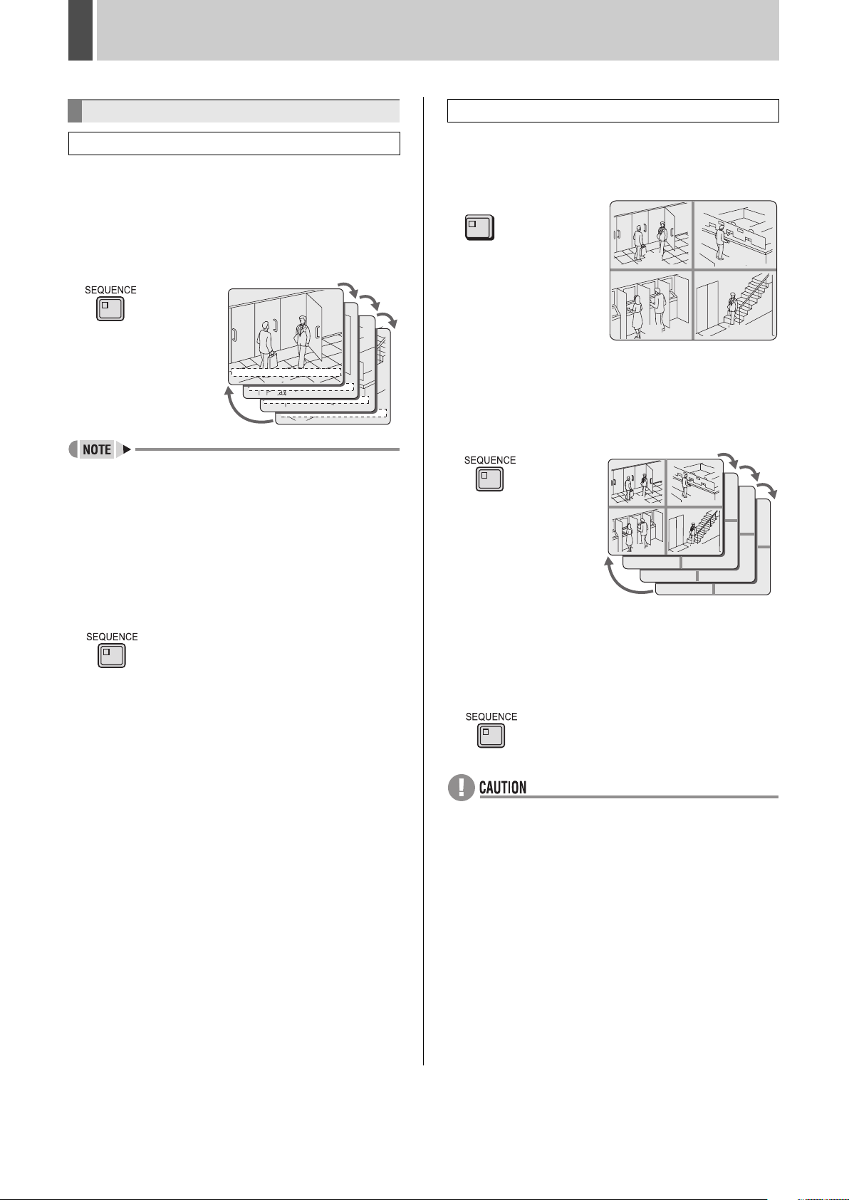
1 Press the [SEQUENCE] button.
The SEQUENCE indicator flashes and the displayed video
changes automatically based on the camera number.
The current camera number indicator lights sequentially.
01-01-05 00:00:00 EN A
z It is possible to specify the cameras for which automatic
selection is to be carried out. (JP.68)
01
01-01-05 00:00:00 ENA
02
01-01-05 00:00:00 ENA
03
01-01-05 00:00:00 ENA
04
Setting automatic quad-screen selection
1 Press the [QUAD] button.
The QUAD indicator lights up and video from four separate
cameras is displayed simultaneously.
QUAD
0201
0403
2 Press the [SEQUENCE] button.
The four images on the quad screen automatically change in
order of cameras No. 1-4, 5-8, 9-12 and 13-16.
On the DSR-5009P, the video changes automatically in order
of cameras No. 1-4, 5-8, 9-3, etc.
01
02
2 Press the [SEQUENCE] button to end
automatic selection.
Automatic selection ends and the display returns to the
normal screen.
z Pressing a [CAMERA SELECT] button, the [QUAD] button,
the [MULTI] button or [PLUS] button also ends automatic
selection.
03
07
04
08
11
12
15
16
3 Press the [SEQUENCE] button to return
to normal quad-screen display.
Automatic selection ends and the display returns to the
normal quad-screen.
Even if the [CAMERA SELECT], [QUAD], [MULTI], or [PLUS]
button are pressed, the display returns to quad screens.
z Automatic selection cannot be used with playback video.
English 25
Page 27
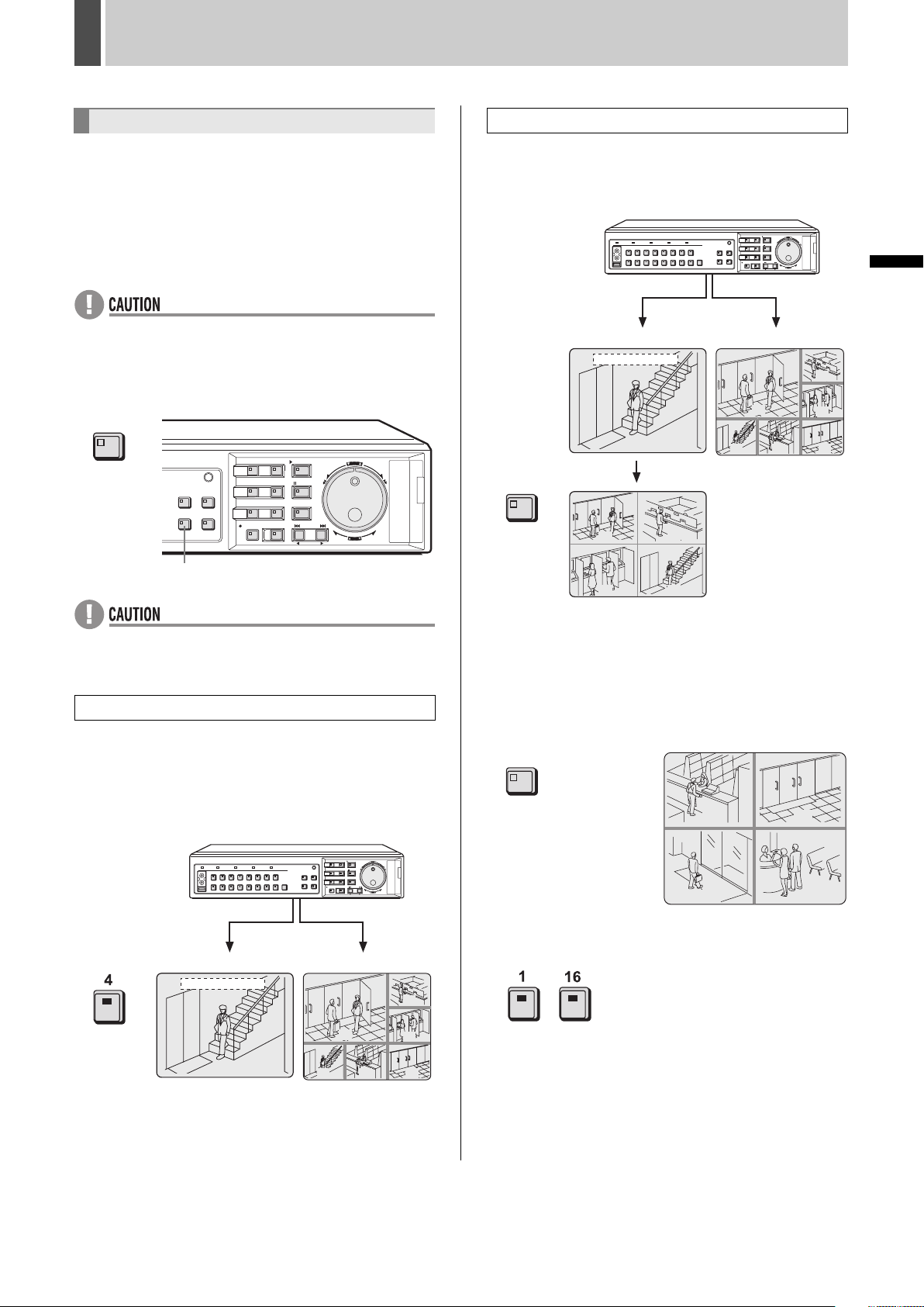
MONITORING VIDEO FROM A CAMERA2
Viewing on monitor 2
When a monitor is connected to the MON2 output terminal on
the rear panel of the digital video recorder, this monitor can be
used to view video in quad screen or multi screen format or
automatically scroll through video from all cameras
independent of the display on the main monitor. In addition, it
is also possible to display video on monitor 2 automatically
from any camera for which an alarm has occurred. By default,
automatic full screen selection is performed.
Use the [MON2] button to change the monitor 2 setting.
z The playback image cannot be viewed on Monitor 2.
1 Press the [MON2] button.
The MON2 indicator lights up.
MON2
[MON2] button
Viewing on a quad screen
2 Press the [QUAD] button.
The video from cameras No. 1 through 4 is displayed in quad
screen on monitor 2.
QUAD
Monitor 2
01-01-05 00:00:00
04
01
03
02
04
Main monitor
01
03
06
0907 08
INTRODUCTION SETTINGS NETWORK
CONTROL
z Monitor 2 is not available while a menu screen is being
displayed, search menu is being operated or camera is
being controlled.
Viewing on a full screen
Example: Selecting Camera 4
2 Press the No. 4 [CAMERA SELECT]
button.
The video from Camera No. 4 is displayed in full screen on
monitor 2.
Monitor 2
01-01-05 00:00:00
04
Main monitor
01
03
06
0907 08
3 To view video from another camera,
press the [QUAD] button again.
Each time this button is pressed, the four images on the quad
screen change, in order of cameras No. 1-4, 5-8, 9-12 and 13-
16.
On the DSR-5009P, the images change in order of cameras
No. 1-4, 5-8, 9-3, etc.
QUAD
0605
0807
4 To return to full screen display, press a
[CAMERA SELECT] button.
-
On the DSR-5009P, press the [CAMERA SELECT] 1-9
button.
NETWORK
OPERATION
NETWORK
SETTINGS
OTHEROPERATION
26 English
Page 28
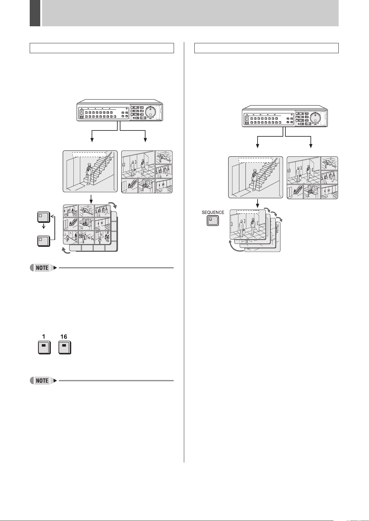
MONITORING VIDEO FROM A CAMERA2
Viewing on multi 9 or multi 16 screens
2 Press the [MULTI] button.
The video from the cameras is displayed in multi 9 screens on
monitor 2. Press the [MULTI] button again to display multi 16
screens.
The DSR-5009P can only display video from nine cameras.
Main monitor
01
03
06
0907 08
MULTI
Monitor 2
01-01-05 00:00:00
04
01
0302
Setting automatic full screen selection
2 Press the [SEQUENCE] button.
The video displayed on monitor 2 changes automatically.
Press the [SEQUENCE] button once again to cancel
automatic selection.
Even if the [CAMERA SELECT], [QUAD], [MULTI], or [PLUS]
button are pressed, automatic selection is cancelled.
Monitor 2
01-01-05 00:00:00
04
01-01-05 00:00:00
Main monitor
01
03
06
0907 08
MULTI
04
07 08 09
13 14 15 16
06
05
z In the case of both quad and multi 9/16 screen display, you
can change the positions in which video from the various
cameras is displayed. (JP.126)
On the DSR-5009P, display positions can be changed on
quad and multi 9 screens.
3 To return to full screen display, press a
[CAMERA SELECT] button.
-
On the DSR-5009P, press the [CAMERA SELECT] 1-9
button.
z Enlarging video can be displayed on monitor 2.
English 27
Page 29
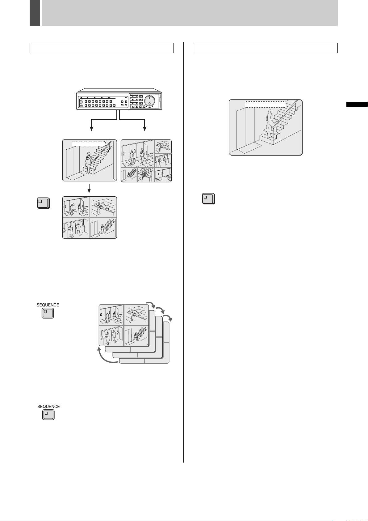
MONITORING VIDEO FROM A CAMERA2
Setting automatic quad-screen selection
2 Press the [QUAD] button.
The video from the cameras is displayed in quad screen on
monitor 2.
Main monitor
01
03
06
0907 08
QUAD
Monitor 2
01-01-05 00:00:00
04
01
03
02
04
Displaying alarm video in full screen format
2 Set “MON.2 DISPLAY” from the
<ALARM OPERATION SET> screen to
“ON”. (JP.103)
When an alarm occurs, the corresponding video is displayed
in full screen on monitor 2.
01-01-05 00:00:00
04
3 Press the [MON2] button to end the
monitor 2 setting procedure.
The MON2 indicator turns off.
MON2
INTRODUCTION SETTINGS NETWORK
CONTROL
3 Press the [SEQUENCE] button.
The four images of the quad screen on monitor 2
automatically change in order of cameras No. 1-4, 5-8, 9-12
and 13-16.
On the DSR-5009P, the video changes automatically in order
of cameras No. 1-4, 5-8, 9-3, etc.
Monitor 2
01
03
07
02
04
08
11
12
15
16
4 Press the [SEQUENCE] button to return
to normal quad-screen display.
Automatic selection ends and normal quad-screen display
returns.
NETWORK
OPERATION
NETWORK
SETTINGS
OTHEROPERATION
28 English
Page 30
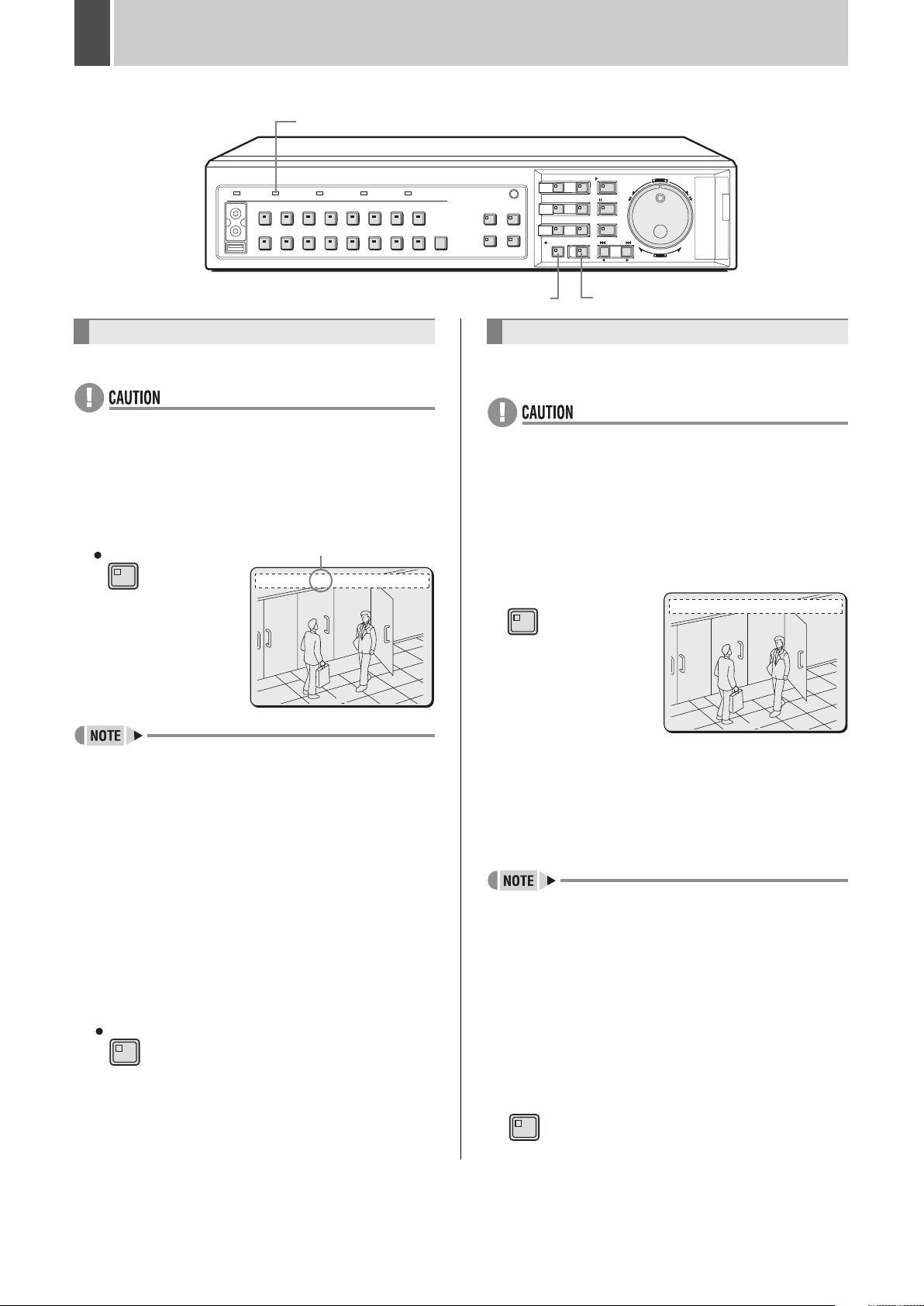
3 RECORDING
FULL indicator
[REC/STOP] button [TIMER] button
Normal recording
Use the following procedure to record monitored video.
z Be sure to set the time when using the digital video
recorder for the first time. Recording is not possible until
the time is set. (JP.20)
1 Press the [REC/STOP] button.
The REC/STOP indicator lights up, “REC” (i.e., the recording
symbol) appears in the operation display and recording starts.
REC/STOP
z When recording for the first time, the default settings are
used. (JP.83)
z When “OVERWRITE” on the <RECORDING
CONDITIONS SET> screen is set to “OFF” and the space
remaining in the recording area becomes insufficient, the
FULL indicator begins to flash. If recording is continued
beyond this point, the recording area becomes full and
recording stops. Perform AREA FULL RESET to enable
recording. (JP.79)
z Playback is possible even while recording. (JP.18)
Recording symbol
01-01-05 00:00:00 REC REPEAT EN A
02
0
2 Press and hold the [REC/STOP] button
for approximately 3 seconds to end
normal recording.
“REC” disappears from the operation display and recording
ends.
REC/STOP
Timer recording
Use the following procedure to record monitored video for a
preset length of time.
z Be sure to set the time when using the digital video
recorder for the first time. Recording is not possible until
the time is set. (JP.20)
1 Set timer recording. (JP.87)
2 Press the [TIMER] button.
The TIMER indicator lights up and the digital video recorder
enters timer recording standby mode.
TIMER
z At the time specified for the start of timer recording, the
REC/STOP indicator lights up, “REC” (i.e., the recording
symbol) appears in the operation display and recording
starts.
z At the time specified for the end of timer recording, the
REC/STOP indicator turns off and recording ends. The
TIMER indicator remains lit. If the [TIMER] button is
pressed, the TIMER indicator turns off.
z When “OVERWRITE” on the <RECORDING
CONDITIONS SET> screen is set to “OFF” and the space
remaining in the recording area becomes insufficient, the
FULL indicator begins to flash. If recording is continued
beyond this point, the recording area becomes full and
recording stops. Perform AREA FULL RESET to enable
recording. (JP.79)
z Playback is possible even while recording.
01-01-05 00:00:00 EN A
02
3 Press the [TIMER] button to end timer
recording before the end time.
The TIMER indicator turns off and recording ends.
TIMER
0
English 29
Page 31

RECORDING3
FULL indicator
Alarm recording
Use the following procedure to record alarm video when an
alarm signal is detected.
1 Set alarm recording. (JP.93)
2 When an alarm signal is detected
z When an alarm signal is detected, “ALARM” flashes in the
operation display and alarm recording starts (indicated by
“REC”.)
z Whenever an alarm occurs, the number of alarms
indicated in the operation display is incremented.
01-01-05 00:00:00 REC REPEAT EN A ALARM 0000001
02
z If an alarm occurs during normal recording or timer
recording, recording ends.
z A maximum of 1,000,000 alarm recordings can be made
on one hard disk. The number of maximum recordings can
be increased to 6,000,000 by expanding the optional hard
disk. However, the maximum number of recordings is
affected by set recording conditions. Be sure to check the
menu settings and display content.
Counts the number of
alarms.
Displays up to
9999999.
After 9999999, the
counter returns to
0000000 and
resumes counting
from 1.
z When “OVERWRITE” on the <RECORDING
CONDITIONS SET> screen is set to “OFF” and the space
remaining in the recording area becomes insufficient, the
FULL indicator begins to flash. If recording is continued
beyond this point, the recording area becomes full and
recording stops. Perform AREA FULL RESET to enable
recording. (JP.79)
Pre-alarm recording
Use the following procedure to record video immediately
before the occurrence of an alarm.
1 Set pre-alarm recording. (JP.96)
“PRE” appears in the operation display. Pre-alarm recording
starts (without the “REC” symbol being displayed).
2 If an alarm is detected
Pre-alarm recording is automatically ended and alarm
recording starts.
z “PRE” disappears from the operation display and “ALARM”
begins to flash.
01-01-05 00:00:00 REC REPEAT EN A ALARM 0000001
INTRODUCTION SETTINGS NETWORK
CONTROL
NETWORK
OPERATION
3 End alarm recording.
When the alarm duration has expired (default setting: 20
seconds), both “REC” and “ALARM” stop flashing on the
operation display and recording stops.
z Be sure to set the time when using the digital video
recorder for the first time. Recording is not possible until
the time is set. (JP.20)
z When alarm recording total exceeds 1,000,000 and
“OVERWRITE” on the <RECORDING CONDITIONS SET>
screen (JP.80) is set to “ON”, older recordings are
overwritten even if the hard disk has remaining memory
capacity.
Alarm recording is not performed when “OFF” is set.
02
z When recording for the first time, the default settings are
used. The image quality and recording rate can be
changed. (JP.97)
z When “OVERWRITE” on the <RECORDING
CONDITIONS SET> screen is set to “OFF” and the space
remaining in the recording area becomes insufficient, the
FULL indicator begins to flash. If recording is continued
beyond this point, the recording area becomes full and
recording stops. Perform AREA FULL RESET to enable
recording. (JP.79)
30 English
NETWORK
SETTINGS
OTHEROPERATION
Page 32

4 PLAY
Use the following procedure to play normal or timer recording video stored in the hard disk.
POWER indicator
[CAMERA SELECT] button
[QUAD] button
[MULTI] button
[ZOOM] button
[SHUTTLE HOLD] button
[PLAY/STOP] button
[STILL] button[PLUS] button
Shuttle dial
Jog dial
Playing video on a full screen
1 Press the [CAMERA SELECT] button for
the camera to play and then press the
[PLAY/STOP] button.
The PLAY/STOP indicator lights up and appears in the
operation display. Normal or timer recording video is played
back. To view video from another camera, press the
[CAMERA SELECT] button of the desired camera.
PLAY/STOP
z Video playback begins at the playback point where the
previous recording ended.
z If the playback point has been reset, video playback begins
from the earliest recording.
z If playback is stopped, the playback point is reset and
playback resumes from that point when the [PLAY/STOP]
button is next pressed.
z When playback ends, the operating display automatically
indicates that playback is paused ( ) and the STILL
indicator lights up.
Operation
display area
01-01-05 00:00:00 EN A
02
2 Press the [PLAY/STOP] button to end
playback.
Playback ends.
PLAY/STOP
Fast-forward and fast-rewind
playback
1 Turn the shuttle dial clockwise or
counter-clockwise during video
playback.
Turn the shuttle dial to use fast-forward and fast-rewind
playback.
When turned clockwise, appears in the operation display
and fast-forward playback begins.
When turned counter-clockwise, appears in the operation
display and fast-rewind playback begins.
Fast-forward and fast-rewind speed increase the more the
shuttle dial is turned.
Return the shuttle dial to continue normal playback.
z Press the [SHUTTLE HOLD] button while either or is
displayed to fix the speed of fast-forward or fast-rewind
playback without having to hold the shuttle dial.
Press the [SHUTTLE HOLD] button again to continue
normal playback.
Changing the playback speed
Starting fast-forward or slow playback
(1) Performing fast-forward.
When the jog dial is turned clockwise, fastforward playback begins and appears in
the operation display.
Fast-forward speed increases the more the
jog dial is turned clockwise and decreases
as it is returned.
Playing video near the point of recording
The digital video recorder priorities recording operations, and
as a result, video playback may pause temporarily.
English 31
(2) Performing slow playback.
When the jog dial is turned counterclockwise, slow playback begins and
appears in the operation display.
Slow playback speed decreases the more
the jog dial is turned counter-clockwise and
increases as it is returned.
Page 33

PLAY4
(3) Returning to normal playback.
Press the [SHUTTLE HOLD] button while
the SHUTTLE HOLD indicator is lit to
release the lock status.
is displayed in the operation display area
when the jog dial is turned.
z Audio is not played during fast-forward, fast-rewind, slow,
reverse-slow and reverse playback.
Using reverse playback, fast-rewind, and
reverse-slow playback
(1) Performing reverse playback.
Turn the shuttle dial slightly counterclockwise during playback to use reverse
playback at normal speed. is displayed
in the operation display area.
z Press the [SHUTTLE HOLD] button while is displayed to
fix the reverse playback speed without having to hold the
shuttle dial.
(2) Performing fast-rewind playback.
While in reverse playback, turn the jog dial
counter-clockwise to use fast rewind. is
displayed in the operation display area.
Fast-rewind speed increases the more the
jog dial is turned counter-clockwise and
decreases as it is returned.
Magnifying the playback video
1 Press the [ZOOM] button during
playback.
Press the button corresponding to the camera for which video
is being magnified.
The ZOOM indicator lights up and a blue zoom frame appears
in the center of the screen.
ZOOM
2 Move the zoom frame to the area to be
magnified.
z Turn the jog dial to move the zoom frame to the left or right.
z Turn the shuttle dial clockwise and then turn the jog dial to
move the zoom frame vertically.
INTRODUCTION SETTINGS NETWORK
CONTROL
(3) Performing reverse-slow playback.
While in reverse playback, turn the jog dial
clockwise to use reverse slow playback.
is displayed in the operation display
area.
Reverse slow playback speed decreases
the more the jog dial is turned clockwise
and increases as it is returned.
(4) Returning to normal playback.
Press the [SHUTTLE HOLD] button while
the SHUTTLE HOLD indicator is lit to
release the lock status. is displayed in
the operation display area when the jog dial
is turned.
Move the zoom frame to the area to be magnified.
3 Turn the shuttle dial clockwise.
The area enclosed by the zoom frame is magnified (by a
factor of 2).
02
NETWORK
OPERATION
NETWORK
SETTINGS
OTHEROPERATION
32 English
Page 34

PLAY4
4 Press the [ZOOM] button to return to
normal magnification.
Magnification is cancelled and the display returns to the
normal screen.
The ZOOM indicator turns off.
ZOOM
02
z Magnified video has a slightly coarser appearance when
compared with normal video.
z Images cannot be enlarged in multi-screen format.
z If a [CAMERA SELECT] button is pressed or playback is
stopped, magnification is cancelled.
Viewing still images
Pause playback and display still images.
1 Press the [STILL] button during
playback.
The STILL indicator lights up and playback video is paused.
appears in the operation display.
STILL
01-01-05 00:00:00 EN A
Frame advance (forward/reverse)
1 Turn the jog dial while playback is
paused.
Clockwise: The still image is moved forward by one frame or
field.
Counter-clockwise: The still image is moved back by one
frame or field.
01-01-05 00:00:00
z If normal, fast-forward or fast-rewind playback is performed
either for playback during alarm recording or for continuous
playback from the normal recording area and alarm
recording area, the image may appear to pause in certain
cases.
z The jog dial can be turned to increase the speed of frame
advance.
Playing video on multiple screens
When recording video from a number of different cameras, the
following procedures can be used to play the recorded video
in multi-screen format.
EN A
02
02
2 Press the [STILL] button again to
resume normal playback.
Normal playback is resumes.
STILL
Playing video on quad screens
1 Press the [QUAD] button during
playback.
The QUAD indicator lights up and video from four separate
cameras is displayed simultaneously.
QUAD
0201
0403
English 33
Page 35

PLAY4
2 To view video from other cameras,
press the [QUAD] button again.
Each time this button is pressed, the four images on the quad
screen change, in order of cameras No. 1-4, 5-8, 9-12 and 13-
16.
On the DSR-5009P, the images change in order of cameras
No. 1-4, 5-8, 9-3, etc.
QUAD
0605
0807
3 To return to full screen display, press a
[CAMERA SELECT] button.
-
On the DSR-5009P, press the [CAMERA SELECT] 1-9
button.
Playing enlarged video
1
Press the [PLUS] button during playing
video on full, quad, multi 9 or multi 16
screens.
On the DSR-5009P, press the button on full, quad or multi 9
screens.
The PLUS indicator lights up and one camera image is enlarged.
PLUS
01
01
04
04
05
05
0707 090808
0302
0302
06
06
09
02
0707
0303
03
06
0808
09
2 Press a [CAMERA SELECT] button.
Example: Select Camera No. 2.
The selected camera image is enlarged.
01
0302
03
INTRODUCTION SETTINGS NETWORK
Playing video on multi 9 or multi 16 screens
1 Press the [MULTI] button during
playback.
The MULTI indicator lights up and video from 16 separate
cameras is displayed simultaneously. Press the [MULTI]
button again to display multi 9 screens.
The DSR-5009P can only display video from nine cameras.
MULTI
03
02
MULTI
01
01
05 06
04
09 11 12
10
13 14 15
07 08 09
04
0302
08
07
06
05
16
2 To return to full screen display, press a
[CAMERA SELECT] button.
-
On the DSR-5009P, press the [CAMERA SELECT] 1-9
button.
z In the case of both quad and multi 9/16 screen display, you
can change the positions in which playback video from the
various cameras is displayed. (JP.126)
04
02
05
07 08 09
07 08 09
06
06
3 Press the [MULTI] button during plus
screen display to change display.
MULTI
0303
03
02
0707
On the DSR-5009P, pressing the [MULTI] button does not
change the display.
06
0808
09
09 11 12
13 14 15
03
04
02
10
08
07
16
4 Press the [PLUS] button during plus
screen display to leave the enlarged
camera image as is and to switch to
monitoring video (live image) for other
camera numbers.
5 Press the [PLUS] button to return to the
screen from before enlarging video.
PLUS
CONTROL
NETWORK
OPERATION
NETWORK
SETTINGS
OTHEROPERATION
z When playing back all videos, “PLUS” is displayed for
channels that are played back in enlarging video.
34 English
Page 36

5 SEARCHING FOR RECORDED VIDEO
0011
[CAMERA SELECT] button
Video stored in the recording area or archive area can be
located by searching and then played back. Use one of six
search methods to locate the required video.
Archive area
Recording area
<SEARCH> screen
SEARCH
(1)
(2)
(3)
(4)
<SEARCH>
ALARM LOG SEARCH ->
ALARM SEARCH ->
ALARM THUMBNAIL SEARCH ->
TIME/DATE SEARCH ->
ARCHIVE AREA SEARCH ->
MOTION DETECTION SEARCH ->
(5)
(6)
MOVE:JOG SELECT:SHUTTLE
z During playback, use the shuttle dial, jog dial or operation
buttons to perform operations, such as to pause or fastforward playback.
(1) ALARM LOG SEARCH (JP.36)
Search with reduced
alarm image time.
< ALARM LOG SEARCH > TERM : MONTH
01-01-05 1 5 10 15 20 25 30
01
02
03
04
05
06
07
08
09
10
11
12
13
14
15
16
SRARCH:ALARM
(2) ALARM SEARCH (JP.37)
Search and play back
alarm video from the
recording list. Search also
by alarm or camera
number.
NO DATE TIME CH TOTAL ALARMS :0000028
0000028 10-05 19:15 01 SEARCH :0000028
0000027 10-05 18:57 02 CHANNEL :
0000026 10-05 18:55 03
0000025 10-05 18:52 03
0000024 10-05 22:05 01
0000023 10-05 21:59 05
0000022 10-05 21:33 04
0000021 10-05 21:25 06
< ALARM SEARCH >
MOVE:JOG SELECT:SHUTTLE
[FUNC.] button
(3) ALARM THUMBNAIL SEARCH (JP.40)
Search and play back
alarm video using a
thumbnail list. Search also
by alarm or camera
number.
(4) TIME/DATE SEARCH (JP.42)
Search and play back
recorded video by date
and time.
(5) ARCHIVE AREA SEARCH (JP.44)
Playback video that has
been stored in the archive
area. Search also by
archive or camera number.
(6) MOTION DETECTION SEARCH (JP.45)
Search and play back video of moving objects detected by
motion sensors.
SEARCH FROM : ALARM
START : 12-09-03 09:25
END : 20-10-03 15:50
CHANNEL : --
START PREVIEW ->
[SEARCH] button
[ALARM] button
< TIME/DATE SEARCH >
RECORDING TOP : 24-10-05 18:00
RECORDING END : 30-10-05 19:00
CHANNEL : 01
SEARCH :
DATE TIME
25-10-05 12:32
PREVIEW ->
VIEW ->
NO DATE START CH CAPACITY
0000001 20-10 14:15 01 TOTAL - 800MB
0000002 20-10 15:15 01 USED - 105MB
0000003 20-10 16:15 01
0000004 20-10 17:15 01
0000005 20-10 18:15 01
0000006 20-10 19:15 01
< MOTION DETECTION SEARCH >
MOVE:JOG SELECT:SHUTTLE
Shuttle dial
Jog dial
0000028 0000027 0000026
0011
0000025 0000024
0000022 0000021 0000020
CHANGE:JOG SET:SHUTTLE
< ARCHIVE AREA SEARCH >
MOVE:JOG SELECT:SHUTTLE
LEVEL:OFF EXIT
0000023
English 35
Page 37

SEARCHING FOR RECORDED VIDEO5
Alarm log search
Use the following procedure to perform an alarm search or
alarm thumbnail search by defining the period (month, week,
day or time) of the alarm recorded video.
1 Press the [SEARCH] button while the
digital video recorder is recording or
stopped.
The SEARCH indicator lights up and the <SEARCH> screen
is displayed.
SEARCH
<SEARCH>
ALARM LOG SEARCH ->
ALARM SEARCH ->
ALARM THUMBNAIL SEARCH ->
TIME/DATE SEARCH ->
ARCHIVE AREA SEARCH ->
MOTION DETECTION SEARCH ->
MOVE:JOG SELECT:SHUTTLE
2 Turn the jog dial to select “ALARM LOG
SEARCH” and then turn the shuttle dial
clockwise.
The <ALARM LOG SEARCH> screen is displayed.
Date, day or time
< ALARM LOG SEARCH > TERM:MONTH
01-01-05 1 5 10 15 20 25 30
01
02
03
04
05
06
07
Camera
number
On the DSR-5009P, cameras No. 01-09 are displayed.
08
09
10
11
12
13
14
15
16
SEARCH:ALARM
4 Turn the jog dial to select “TERM” and
then turn the shuttle dial clockwise.
The screen display changes to reflect the specified period.
Press the or [ALARM] button to change the month/
week/date/time.
< ALARM LOG SEARCH > TERM:DAY
01-01-05 00 06 12 18
01
02
03
04
05
06
07
08
09
10
11
12
13
14
15
16
SEARCH:ALARM
[Settings] ( indicates default setting)
Setting Description
MONTH Displays one month.
WEEK Displays one week.
DAY Displays one day.
HOUR Displays one hour.
5 Turn the jog dial to select the date, time
or minute and then turn the shuttle dial
clockwise.
The selected day (or hour or minutes) is indicated with a
yellow frame.
Alarm recording areas are indicated in red and areas with no
recordings in gray.
Reselecting the area cancels the original selected area.
To confirm normal recording
Press the [FUNC.] button to search for normal recording. A
blue mark is displayed at the top left of the screen, and
normally recorded parts are displayed in blue. (The search for
normal recording may take some time.)
To abort the search, turn the shuttle dial counter-clockwise.
INTRODUCTION SETTINGS NETWORK
CONTROL
NETWORK
OPERATION
3 Turn the shuttle dial clockwise.
The “TERM” setting flashes.
< ALARM LOG SEARCH > TERM:MONTH
01-01-05 1 5 10 15 20 25 30
01
02
03
04
05
06
07
08
09
10
11
12
13
14
15
16
SEARCH:ALARM
< ALARM LOG SEARCH > TERM:DAY
01-01-05 00 06 12 18
01
02
03
04
05
06
07
08
09
10
11
12
13
14
15
16
SEARCH:ALARM
z If “MONTH” is selected in step 4 above, each frame
represents one day. If “WEEK” is selected, four frames
represent one day. If “DAY” is selected, each frame
represent one hour. If “HOUR” is selected, each frame
represents two minutes.
NETWORK
SETTINGS
OTHEROPERATION
36 English
Page 38

SEARCHING FOR RECORDED VIDEO5
6 Turn the jog dial to select “SEARCH”
and then turn the shuttle dial clockwise.
“ALARM” flashes.
< ALARM LOG SEARCH > TERM:DAY
01-01-05 00 06 12 18
01
02
03
04
05
06
07
08
09
10
11
12
13
14
15
16
SEARCH:ALARM
7 Turn the jog dial to select “ALARM” or
“THUMBNAIL” and then turn the shuttle
dial clockwise.
Now perform alarm search (JP.37) or alarm thumbnail search
(JP.40).
[Settings] ( indicates default setting)
Setting Description
ALARM
THUMBNAIL
The <ALARM SEARCH> screen (JP.37)
is displayed and the search results are
displayed in a list.
The <ALARM THUMBNAIL SEARCH>
screen (JP.40) is displayed and the
search results are displayed in a list.
Alarm search
Use the following procedure to search and play back alarm
video. If pre-alarm video is being recorded, video from
immediately before the alarm can also be played back.
1 Press the [SEARCH] button while the
digital video recorder is recording or
stopped.
The SEARCH indicator lights up and the <SEARCH> screen
is displayed.
SEARCH
<SEARCH>
ALARM LOG SEARCH ->
ALARM SEARCH ->
ALARM THUMBNAIL SEARCH ->
TIME/DATE SEARCH ->
ARCHIVE AREA SEARCH ->
MOTION DETECTION SEARCH ->
MOVE:JOG SELECT:SHUTTLE
2 Turn the jog dial to select “ALARM
SEARCH” and then turn the shuttle dial
clockwise.
The <ALARM SEARCH> screen is displayed.
This screen lists the eight most recent alarm recordings.
(1) (2) (3) (4)
NO DATE TIME CH TOTAL ALARMS :0000028
0000028 10-05 19:15 01 SEARCH :0000028
0000027 10-05 18:57 02 CHANNEL :
0000026 10-05 18:55 03
0000025 10-05 18:52 03
0000024 10-05 22:05 01
0000023 10-05 21:59 05
0000022 10-05 21:33 04
0000021 10-05 21:25 06
(1) NO:
Indicates the alarm number.
(2) DATE/TIME:
Indicates the date and time at which the alarm video was
recorded.
(3) CH:
Indicates the alarm video’s channel (or camera number).
(4) TOTAL ALARMS:
Indicates the total number of alarm video recordings.
(5) SEARCH:
Search by specifying an alarm number. (JP.38)
(6) CHANNEL:
Search by specifying a camera number. (JP.39)
(7) Preview:
Displays the selected alarm video.
< ALARM SEARCH >
(5)
(6)
(7)
MOVE:JOG SELECT:SHUTTLE
English 37
Page 39

SEARCHING FOR RECORDED VIDEO5
3 Turn the jog dial to select the video for
playback from the list.
A preview of the selected alarm video is displayed in the
preview screen. In this case, the video at the time the alarm
occurred is displayed.
NO DATE TIME CH TOTAL ALARMS :0000028
0000028 10-05 19:15 01 SEARCH :0000028
0000027 10-05 18:57 02 CHANNEL :
0000026 10-05 18:55 03
0000025 10-05 18:52 03
0000024 10-05 22:05 01
0000023 10-05 21:59 05
0000022 10-05 21:33 04
0000021 10-05 21:25 06
z To display the next or previous recording
Turn the jog dial clockwise or counter-clockwise
accordingly.
z Press the [ALARM] button to display the next eight
recordings, and for the previous eight recordings.
z To end search mode
Press the [SEARCH] button. The SEARCH indicator turns
off.
< ALARM SEARCH >
MOVE:JOG SELECT:SHUTTLE
4 Turn the shuttle dial clockwise.
The selected recording is played back on multi 16 screens.
Playback is also available for another camera image being
recorded simultaneously.
On the DSR-5009P, the recording is played back on multi 9
screens.
01-01-05 00:00:00 EN A ALARM 0000028
SA 01
z When searching by specifying a camera number, playback
is performed on a full screen.
02 03 04
05 06 07 08
09 10 11 12
13 14 15 16
Entering an alarm number to search for an
alarm video
1 In the search screen, press the [FUNC.]
button and select “SEARCH”.
FUNC.
NO DATE TIME CH TOTAL ALARMS :0000028
0000028 10-05 19:15 01 SEARCH :0000028
0000027 10-05 18:57 02 CHANNEL :
0000026 10-05 18:55 03
0000025 10-05 18:52 03
0000024 10-05 22:05 01
0000023 10-05 21:59 05
0000022 10-05 21:33 04
0000021 10-05 21:25 06
< ALARM SEARCH >
MOVE:JOG SELECT:SHUTTLE
2 Turn the shuttle dial clockwise.
The “SEARCH” input field flashes.
NO DATE TIME CH TOTAL ALARMS :0000028
0000028 10-05 19:15 01 SEARCH :0000028
0000027 10-05 18:57 02 CHANNEL :
0000026 10-05 18:55 03
0000025 10-05 18:52 03
0000024 10-05 22:05 01
0000023 10-05 21:59 05
0000022 10-05 21:33 04
0000021 10-05 21:25 06
< ALARM SEARCH >
MOVE:JOG SELECT:SHUTTLE
3 Turn the jog dial and shuttle dial to
select an alarm number.
Turn the shuttle dial to move through the field and turn the jog
dial to select individual numbers (0 through 9).
< ALARM SEARCH >
MOVE:JOG SELECT:SHUTTLE
Numbers can be entered
with the camera number
1-9 buttons or the [QUAD]
button (0).
NO DATE TIME CH TOTAL ALARMS :0000028
0000028 10-05 19:15 01 SEARCH :0000028
0000027 10-05 18:57 02 CHANNEL :
0000026 10-05 18:55 03
0000025 10-05 18:52 03
0000024 10-05 22:05 01
0000023 10-05 21:59 05
0000022 10-05 21:33 04
0000021 10-05 21:25 06
INTRODUCTION SETTINGS NETWORK
CONTROL
NETWORK
OPERATION
NETWORK
SETTINGS
To view pre-alarm video
After beginning playback of an alarm video identified by an
alarm search, use the shuttle dial to reverse playback.
OTHEROPERATION
38 English
Page 40

SEARCHING FOR RECORDED VIDEO5
4 Turn the shuttle dial clockwise.
The alarm video with the specified number is displayed in the
preview screen.
Image numbers before the selected number are displayed in a
list on the left of the screen.
NO DATE TIME CH TOTAL ALARMS :0000028
0000028 10-05 19:15 01 SEARCH :0000028
0000027 10-05 18:57 02 CHANNEL :-0000026 10-05 18:55 03
0000025 10-05 18:52 03
0000024 10-05 22:05 01
0000023 10-05 21:59 05
0000022 10-05 21:33 04
0000021 10-05 21:25 06
< ALARM SEARCH >
MOVE:JOG SELECT:SHUTTLE
5 Press the [FUNC.] button.
The cursor moves to the list.
FUNC.
NO DATE TIME CH TOTAL ALARMS :0000028
0000028 10-05 19:15 01 SEARCH :0000028
0000027 10-05 18:57 02 CHANNEL :-0000026 10-05 18:55 03
0000025 10-05 18:52 03
0000024 10-05 22:05 01
0000023 10-05 21:59 05
0000022 10-05 21:33 04
0000021 10-05 21:25 06
< ALARM SEARCH >
MOVE:JOG SELECT:SHUTTLE
6 Turn the jog dial to select the alarm
video for playback and then turn the
shuttle dial clockwise.
The selected recording is played back on multi 16 screens.
Playback is also available for another camera image being
recorded simultaneously.
On the DSR-5009P, the recording is played back on multi 9
screens.
Entering a camera number to search for an
alarm video
1 In the search screen, press the [FUNC.]
button and select “CHANNEL” with the
jog dial.
FUNC.
NO DATE TIME CH TOTAL ALARMS :0000028
0000028 10-05 19:15 01 SEARCH :0000028
0000027 10-05 18:57 02 CHANNEL :
0000026 10-05 18:55 03
0000025 10-05 18:52 03
0000024 10-05 22:05 01
0000023 10-05 21:59 05
0000022 10-05 21:33 04
0000021 10-05 21:25 06
< ALARM SEARCH >
MOVE:JOG SELECT:SHUTTLE
2 Turn the shuttle dial clockwise.
The “CHANNEL” input field flashes.
NO DATE TIME CH TOTAL ALARMS :0000028
0000028 10-05 19:15 01 SEARCH :0000028
0000027 10-05 18:57 02 CHANNEL :
0000026 10-05 18:55 03
0000025 10-05 18:52 03
0000024 10-05 22:05 01
0000023 10-05 21:59 05
0000022 10-05 21:33 04
0000021 10-05 21:25 06
< ALARM SEARCH >
MOVE:JOG SELECT:SHUTTLE
3 Press the [CAMERA SELECT] button for
the camera number to search.
The alarm video with the specified number is displayed in the
preview screen.
01-01-05 00:00:00 EN A ALARM 0000028
SA 01
02 03 04
05 06 07 08
09 10 11 12
13 14 15 16
z When searching by specifying a camera number, playback
is performed on a full screen.
-
NO DATE TIME CH TOTAL ALARMS :0000028
0000028 10-05 19:15 07 SEARCH :0000028
0000027 10-05 18:57 07 CHANNEL : 7
0000026 10-05 18:55 07
0000025 10-05 18:52 07
0000024 10-05 22:05 07
0000023 10-05 21:59 07
0000022 10-05 21:33 07
0000021 10-05 21:25 07
< ALARM SEARCH >
MOVE:JOG SELECT:SHUTTLE
English 39
Page 41

SEARCHING FOR RECORDED VIDEO5
0011
4 Press the [FUNC.] button.
The cursor moves to the list.
FUNC.
NO DATE TIME CH TOTAL ALARMS :0000028
0000028 10-05 19:15 07 SEARCH :0000028
0000027 10-05 18:57 07 CHANNEL : 7
0000026 10-05 18:55 07
0000025 10-05 18:52 07
0000024 10-05 22:05 07
0000023 10-05 21:59 07
0000022 10-05 21:33 07
0000021 10-05 21:25 07
< ALARM SEARCH >
MOVE:JOG SELECT:SHUTTLE
5 Turn the jog dial to select the alarm
video for playback and then turn the
shuttle dial clockwise.
01-01-05 00:00:00 EN A ALARM 0000000
02
To view alarm video before or after the current
playback
Alarm thumbnail search
Use the following procedure to select alarm videos in the
recording area from a thumbnail list.
1 Press the [SEARCH] button while the
digital video recorder is recording or
stopped.
The SEARCH indicator lights up and the <SEARCH> screen
is displayed.
SEARCH
<SEARCH>
ALARM LOG SEARCH ->
ALARM SEARCH ->
ALARM THUMBNAIL SEARCH ->
TIME/DATE SEARCH ->
ARCHIVE AREA SEARCH ->
MOTION DETECTION SEARCH ->
MOVE:JOG SELECT:SHUTTLE
2 Turn the jog dial to select “ALARM
THUMBNAIL SEARCH” and then turn
the shuttle dial clockwise.
This screen lists the nine most recent alarm recordings.
An alarm number and camera number are indicated together
with each alarm recording, and the number of the currently
selected recording flashes.
INTRODUCTION SETTINGS NETWORK
CONTROL
1 Press the [ALARM] button during
playback.
ALARM
z Each time the button is pressed, playback skips to the
preceding alarm video.
z Each time the button is pressed, playback skips to the
subsequent alarm video.
z When playback is performed after an alarm search, the
frame at the start and end of each alarm recording is
paused.
Press the [ALARM] button to play the previous or next
recording.
z Use the front-panel buttons, the shuttle dial and the jog dial
to perform operations such as pause and fast-forward.
01-01-05 00:00:00 EN A ALARM 0000000
02
0000028 0000027 0000026
04
0000025 0000024
07
0000022 0000021 0000020
02 0301
05
08
0011
0000023
06
NETWORK
OPERATION
09
NETWORK
SETTINGS
OTHEROPERATION
40 English
Page 42

SEARCHING FOR RECORDED VIDEO5
0011
0011
3 Turn the jog dial to select the video for
playback.
The alarm number for the selected video flashes.
0000028 0000027 0000026
04
0000025 0000024
07
0000022 0000021 0000020
z To display the next or previous recording
Turn the jog dial clockwise or counter-clockwise
accordingly.
z Press the [ALARM] button to display the next nine
recordings, and for the previous nine recordings.
z To end search mode
Press the [SEARCH] button. The SEARCH indicator turns
off.
02 0301
05
08
0011
0000023
06
09
4 Turn the shuttle dial clockwise.
The selected recording is played back on multi 16 screens.
Playback is also available for another camera image being
recorded simultaneously.
On the DSR-5009P, the recording is played back on multi 9
screens.
01-01-05 00:00:00 EN A ALARM 0000028
SA 01
02 03 04
Search by entering an alarm number
1 In the search screen, press the [FUNC.]
button.
The “SEARCH” and “CHANNEL” input fields are displayed.
FUNC.
0000028 0000027 0000026
04
0000025 0000024
07
0000022 0000021 0000020
02 0301
SEARCH :0000028
CHANNEL :--
05
0000023
08
06
09
2 Turn the shuttle dial clockwise.
The
“SEARCH”
input field flashes.
0000028 0000027 0000026
0000025 0000024
0000022 0000021 0000020
02 0301
SEARCH :0000028
CHANNEL :--
04
07
05
08
0000023
06
09
3 Select alarm number by turning the jog
dial and shuttle dial.
Move the unit place with the shuttle dial and select numbers 09 with the jog dial.
05 06 07 08
09 10 11 12
13 14 15 16
z In the same way as for alarm searching, only alarm
recordings can be played back. Press the [ALARM] button
to play the previous or next recording.
z When searching by specifying a camera number, playback
is performed on a full screen. (JP.42)
02 0301
SEARCH :0000028
CHANNEL :--
05
0000023
06
Numbers can be entered
with the camera number
0000028 0000027 0000026
04
0000025 0000024
1-9 buttons or the
[QUAD] button (0).
07
0000022 0000021 0000020
08
09
4 Turn the shuttle dial clockwise.
The specified number alarm is searched for and thumbnails
are displayed.
Press the [FUNC.] button to cancel SEARCH and CHANNEL
input fields.
0000028 0000027 0000026
04
0000025 0000024
07
0000022 0000021 0000020
02 0301
SEARCH :0000028
CHANNEL :--
05
08
0011
0000023
06
09
English 41
Page 43

SEARCHING FOR RECORDED VIDEO5
0011
Search by entering a camera number
1 In the search screen, press the [FUNC.]
button and select “CHANNEL” with the
jog dial.
FUNC.
0000028 0000027 0000026
04
0000025 0000024
07
0000022 0000021 0000020
02 0301
SEARCH :0000028
CHANNEL :--
05
0000023
08
06
09
2 Turn the shuttle dial clockwise.
The “CHANNEL” input field flashes.
0000028 0000027 0000026
04
0000025 0000024
07
0000022 0000021 0000020
02 0301
SEARCH :0000028
CHANNEL :--
05
0000023
08
06
09
Time/date search
Search and play back video in the recording area (normal
recording, timer recording, alarm recording) by specifying
camera number, date, or time.
Example: To search for a recording from camera 5 from
8:30 pm on 26 October, 2005
1 Press the [SEARCH] button while the
digital video recorder is recording or
stopped.
The SEARCH indicator lights up and the <SEARCH> screen
is displayed.
SEARCH
<SEARCH>
ALARM LOG SEARCH ->
ALARM SEARCH ->
ALARM THUMBNAIL SEARCH ->
TIME/DATE SEARCH ->
ARCHIVE AREA SEARCH ->
MOTION DETECTION SEARCH ->
MOVE:JOG SELECT:SHUTTLE
2 Turn the jog dial to select “TIME/DATE
SEARCH” and then turn the shuttle dial
clockwise.
The <TIME/DATE SEARCH> screen is displayed.
INTRODUCTION SETTINGS NETWORK
CONTROL
3 Press the [CAMERA SELECT] button for
the camera number to search.
The specified camera number alarm is searched for and
thumbnails are displayed.
Press the [FUNC.] button to cancel SEARCH and CHANNEL
input fields.
-
0000028 0000027 0000026
07
0000025 0000024
07
0000022 0000021 0000020
07 0707
SEARCH :0000028
CHANNEL :-7
07
07
0011
0000023
07
07
4 Turn the shuttle dial clockwise.
(1)
(3)
(5)
< TIME/DATE SEARCH >
RECORDING TOP : 24-10-05 18:00
(2)
RECORDING END : 30-10-05 19:00
CHANNEL : 01
(4)
SEARCH :
DATE TIME
25-10-05 12:32
PREVIEW ->
(6)
VIEW ->
CHANGE:JOG SET:SHUTTLE
(1) RECORDING TOP:
Indicates the date/time of the earliest video recording.
(2) RECORDING END:
Indicates the date/time of the most recent video recording.
(3) CHANNEL:
Input a camera number to search.
(4) SEARCH:
Input date and time to search.
(5) PREVIEW:
Select this option and turn the shuttle dial clockwise to display
the preview screen.
(6) VIEW:
Select this option and turn the shuttle dial clockwise to play
the recording.
NETWORK
OPERATION
NETWORK
SETTINGS
OTHEROPERATION
42 English
Page 44

SEARCHING FOR RECORDED VIDEO5
3 Turn the shuttle dial clockwise while
“CHANNEL” is selected.
The “CHANNEL” input field flashes.
< TIME/DATE SEARCH > [KEY]
RECORDING TOP : 24-10-05 18:00
RECORDING END : 30-10-05 19:00
CHANNEL : - SEARCH :
DATE TIME
25-10-05 12:32
PREVIEW ->
VIEW ->
CHANGE:JOG SET:SHUTTLE
4 Press the [CAMERA SELECT] 5 button.
The cursor moves to “DATE TIME”.
< TIME/DATE SEARCH >
RECORDING TOP : 24-10-05 18:00
RECORDING END : 30-10-05 19:00
CHANNEL : 05
SEARCH :
DATE TIME
25-10-05 12:32
PREVIEW ->
VIEW ->
CHANGE:JOG SET:SHUTTLE
6 Turn the shuttle dial clockwise.
“SEARCHING” is displayed and then the preview screen for
the date and time settings is displayed.
< TIME/DATE SEARCH >
RECORDING TOP : 24-10-05 18:00
RECORDING END : 30-10-05 19:00
CHANNEL : 05
SEARCH :
DATE TIME
26-10-05 20:30
PREVIEW ->
VIEW ->
CHANGE:JOG SET:SHUTTLE
z If no recording exists for the specified time
The closest recording to the specified time is displayed.
z To end search mode
Press the [SEARCH] button to end search mode. The
SEARCH indicator turns off.
7 Turn the jog dial to select “VIEW” and
then turn the shuttle dial clockwise.
The selected recording is played back on the full screen.
5 Specify the date and time.
(1) Turn the shuttle dial clockwise and turn the jog dial to “26”
(day).
(2) Turn the shuttle dial clockwise and turn the jog dial to “10”
(month).
(3) Turn the shuttle dial clockwise and turn the jog dial to “05”
(year).
(4) Turn the shuttle dial clockwise and turn the jog dial to “20”
(hour).
(5) Turn the shuttle dial clockwise, turn the jog dial to “30”
(minutes) and then turn the shuttle dial clockwise again.
The cursor moves to “PREVIEW”
< TIME/DATE SEARCH >
RECORDING TOP : 24-10-05 18:00
RECORDING END : 30-10-05 19:00
Date and time for
searching
26-10-05 20 : 30
(1)
(3)
(2)
z Also use the [CAMERA SELECT] 1-9 button, or the
[QUAD] button (0) to input.
(4)
CHANNEL : 05
SEARCH :
DATE TIME
26-10-05 20:30
PREVIEW ->
VIEW ->
(5)
CHANGE:JOG SET:SHUTTLE
z The retrieved recording can be displayed on the full screen
without displaying the preview screen by entering the date
and time and then selecting “VIEW”.
z If “CHANNEL” is set to “- -” and playback is started, the
recording is displayed on the multi 16 screens (on multi 9
screens for the DSR-5009P).
Press the [CAMERA SELECT] button to view on a full
screen.
English 43
Page 45

SEARCHING FOR RECORDED VIDEO5
Searching within the archive area
Use the following procedure to playback video that has been
stored in the archive area.
1 Press the [SEARCH] button while the
digital video recorder is recording or
stopped.
The SEARCH indicator lights up and the <SEARCH> screen
is displayed.
SEARCH
<SEARCH>
ALARM LOG SEARCH ->
ALARM SEARCH ->
ALARM THUMBNAIL SEARCH ->
TIME/DATE SEARCH ->
ARCHIVE AREA SEARCH ->
MOTION DETECTION SEARCH ->
MOVE:JOG SELECT:SHUTTLE
2 Turn the jog dial to select “ARCHIVE
AREA SEARCH” and then turn the
shuttle dial clockwise.
The <ARCHIVE AREA SEARCH> screen is displayed.
This screen lists the eight most recent recordings in the order
in which archiving was performed.
(2) (4)
(1) (3)
3 Turn the jog dial to select the video for
playback from the list.
The selected image is displayed on the preview screen.
< ARCHIVE AREA SEARCH >
NO DATE START CH CAPACITY
0000001 20-10 14:15 01 TOTAL - 800MB
0000002 20-10 15:15 01 USED - 105MB
0000003 20-10 16:15 01
0000004 20-10 17:15 01
0000005 20-10 18:15 01
0000006 20-10 19:15 01
MOVE:JOG SELECT:SHUTTLE
z To display the next or previous screen
Turn the jog dial clockwise or counter-clockwise
accordingly.
z Press the [ALARM] button to display the next eight
recordings, and for the previous eight recordings.
z Up to eight recordings can be displayed in the <ARCHIVE
AREA SEARCH> screen.
z To end search mode
Press the [SEARCH] button. The SEARCH indicator turns
off.
z Search also by entering the camera number.
4 Turn the shuttle dial clockwise.
The selected recording is played back on the full screen.
INTRODUCTION SETTINGS NETWORK
CONTROL
NO DATE START CH CAPACITY
0000001 20-10 14:15 01 TOTAL - 800MB
0000002 20-10 15:15 01 USED - 105MB
0000003 20-10 16:15 01
0000004 20-10 17:15 01
0000005 20-10 18:15 01
0000006 20-10 19:15 01
< ARCHIVE AREA SEARCH >
(5)
(6)
MOVE:JOG SELECT:SHUTTLE
(1) NO:
Indicates the archive number.
(2) DATE:
Indicates the date of the recording.
(3) START:
Indicates the start time for the recording.
(4) CH:
Indicates the camera number for the stored recording.
(5) TOTAL:
Indicates the total capacity of the archive area.
(6) USED:
Indicates the amount of the archive area that has been used.
NETWORK
OPERATION
NETWORK
SETTINGS
OTHEROPERATION
44 English
Page 46

SEARCHING FOR RECORDED VIDEO5
Entering an archive number to search for an
alarm video
1 In the search screen, press the [FUNC.]
button and select “SEARCH”.
The cursor moves to “SEARCH”.
FUNC.
NO DATE START CH
0000001 20-10 14:15 01 SEARCH : 0000028
0000002 20-10 15:15 01 CHANNEL : --
0000003 20-10 16:15 01
0000004 20-10 17:15 01
0000005 20-10 18:15 01
0000006 20-10 19:15 01
z When the cursor is positioned on “SEARCH”, turn the jog
dial to move the cursor to “CHANNEL”.
< ARCHIVE AREA SEARCH >
MOVE:JOG SELECT:SHUTTLE
2 Turn the shuttle dial clockwise.
The “SEARCH” input field flashes.
NO DATE START CH
0000001 20-10 14:15 01 SEARCH : 0000028
0000002 20-10 15:15 01 CHANNEL : --
0000003 20-10 16:15 01
0000004 20-10 17:15 01
0000005 20-10 18:15 01
0000006 20-10 19:15 01
< ARCHIVE AREA SEARCH >
MOVE:JOG SELECT:SHUTTLE
3 Turn the jog dial and shuttle dial to
select an archive number.
Turn the shuttle dial to move through the field and turn the jog
dial to select a individual numbers (0 through 9).
4 Turn the shuttle dial clockwise.
Data with the specified archive numbers are searched for and
displayed in a list.
NO DATE START CH
0000001 20-10 14:15 01 SEARCH : 0000028
0000002 20-10 15:15 01 CHANNEL : --
0000003 20-10 16:15 01
0000004 20-10 17:15 01
0000005 20-10 18:15 01
0000006 20-10 19:15 01
< ARCHIVE AREA SEARCH >
MOVE:JOG SELECT:SHUTTLE
Motion detection search
By setting the motion sensor for normal, timer or alarm
recordings, variations from normal images as a result of the
presence of an intruder or the like can be detected, and the
corresponding video can be played back.
z When a camera number is specified, searching can only be
performed for that camera.
1 Press the [SEARCH] button while the
digital video recorder is recording or
stopped.
The SEARCH indicator lights up and the <SEARCH> screen
is displayed.
SEARCH
<SEARCH>
ALARM LOG SEARCH ->
ALARM SEARCH ->
ALARM THUMBNAIL SEARCH ->
TIME/DATE SEARCH ->
ARCHIVE AREA SEARCH ->
MOTION DETECTION SEARCH ->
MOVE:JOG SELECT:SHUTTLE
NO DATE START CH
< ARCHIVE AREA SEARCH >
0000001 20-10 14:15 01 SEARCH : 0000028
0000002 20-10 15:15 01 CHANNEL : --
0000003 20-10 16:15 01
0000004 20-10 17:15 01
0000005 20-10 18:15 01
0000006 20-10 19:15 01
MOVE:JOG SELECT:SHUTTLE
z Also use 1-9 on the [CAMERA SELECT] button or the
[QUAD] button (0) to input.
English 45
2 Turn the jog dial to select “MOTION
DETECTION SEARCH” and then turn
the shuttle dial clockwise.
The <MOTION DETECTION SEARCH> screen is displayed.
< MOTION DETECTION SEARCH >
SEARCH FROM : ALARM
START : 12-09-03 09:25
END : 20-10-03 15:50
CHANNEL : --
START PREVIEW ->
MOVE:JOG SELECT:SHUTTLE
Page 47

SEARCHING FOR RECORDED VIDEO5
3 Turn the shuttle dial clockwise.
“SEARCH FROM” input field flashes.
< MOTION DETECTION SEARCH >
SEARCH FROM : ALARM
START : 12-09-03 09:25
END : 20-10-03 15:50
CHANNEL : --
START PREVIEW ->
MOVE:JOG SELECT:SHUTTLE
[Settings] ( indicates default setting)
Setting Description
ALARM Searches alarm recording area.
NORMAL Searches normal recording area.
ALARM &
NORMAL
ARCHIVE
*1
Searches normal and alarm recording
areas.
Search the archive area.
*1 “ARCHIVE” can only be selected when “MODE” in
“ARCHIVE AREA” in the <RECORDING CONDITIONS
SET> screen is set to “AUTO ALARM COPY”. (JP.81)
4 Turn the jog dial to select the “SEARCH
FROM” setting and then turn the shuttle
dial clockwise twice.
The camera number input field flashes.
< MOTION DETECTION SEARCH >
SEARCH FROM : NORMAL
START : 12-09-03 09:25
END : 20-10-03 15:50
CHANNEL : --
START PREVIEW ->
MOVE:JOG SELECT:SHUTTLE
6 Turn the shuttle dial clockwise.
The screen changes and the preview screen for the selected
camera number is displayed.
< MOTION DETECTION SEARCH >
SEARCH FROM : NORMAL / CHANNEL : --
(1)
START :
12-09-03 09:25
(2)
END :
20-10-03 15:50
(3)
(4)
MOTION SENSOR ->
PREVIEW ->
(5)
VIEW ->
MOVE:JOG SELECT:SHUTTLE
(1) START:
The date and time of the first screen of the selected recording
is displayed.
(2) END:
The last date and time of the selected recording is displayed.
(3) MOTION SENSOR:
The motion sensor setting screen is displayed.
(4) PREVIEW:
Displays the selected start image.
(5) VIEW:
Plays the selected recording on the full screen.
z Press the [SEARCH] button to end search mode. The
SEARCH indicator turns off.
Setting the motion sensor for searching
1 Turn the shuttle dial clockwise while
video is being displayed on the preview
screen.
(1) Turn the jog dial to set the start date and time for motion
sensing (i.e., 10 AM on the same day) and then turn the
shuttle dial clockwise.
The recording for the selected time is displayed in the
preview screen. The cursor moves to “END”.
INTRODUCTION SETTINGS NETWORK
CONTROL
NETWORK
OPERATION
5 Press a [CAMERA SELECT] button and
then turn the shuttle dial clockwise.
The cursor moves to “START PREVIEW”.
< MOTION DETECTION SEARCH >
-
SEARCH FROM : NORMAL
START : 12-09-03 09:25
END : 20-10-03 15:50
CHANNEL : --
START PREVIEW ->
MOVE:JOG SELECT:SHUTTLE
< MOTION DETECTION SEARCH >
SEARCH FROM : NORMAL / CHANNEL : --
START :
Set the
start date
and time.
12-09-03 10:00
END :
20-10-03 15:50
MOTION SENSOR ->
PREVIEW ->
VIEW ->
MOVE:JOG SELECT:SHUTTLE
(2) Turn the shuttle dial clockwise.
46 English
NETWORK
SETTINGS
OTHEROPERATION
Page 48

SEARCHING FOR RECORDED VIDEO5
(3) Turn the jog dial to set the end date and time for motion
sensing (i.e., 8 PM on the same day) and then turn the
shuttle dial clockwise.
The cursor moves to “MOTION SENSOR”.
< MOTION DETECTION SEARCH >
SEARCH FROM : NORMAL / CHANNEL : --
START :
12-09-03 10:00
Set the
end date
and time.
END :
12-09-03 20:00
MOTION SENSOR ->
PREVIEW ->
VIEW ->
MOVE:JOG SELECT:SHUTTLE
2 Turn the shuttle dial clockwise.
The motion sensor setting screen is displayed.
Use the following procedure to set to detect a given range with
the motion sensor.
(1) Turn the jog dial to move the starting position to the
desired detection range and then turn the shuttle dial
clockwise.
“ ” changes to a yellow “”.
(5) Turn the shuttle dial clockwise.
The yellow areas change to gray.
LEVEL:OFF EXIT
3 Turn the jog dial to select “LEVEL” and
then turn the shuttle dial clockwise.
“OFF” flashes.
LEVEL:OFF EXIT
LEVEL:OFF EXIT
(2) Turn the jog dial to move left and right.
(3) Press the [FUNC.] button.
Cursor movements can be changed from left and right to
up and down.
FUNC.
LEVEL:OFF EXIT
(4) Turn the jog dial to move up and down.
4 Turn the jog dial to select sensitivity
and then turn the shuttle dial clockwise.
After the sensitivity level is set, the cursor moves to “EXIT”.
LEVEL:OFF EXIT
[Settings] ( indicates default setting)
Setting Description
OFF Motion sensing is not performed.
Motion sensing is performed. Lower
1 to 10
numbers correspond to higher levels of
sensitivity.
5 Turn the shuttle dial clockwise.
The display returns to the <MOTION DETECTION SEARCH>
screen.
< MOTION DETECTION SEARCH >
SEARCH FROM : NORMAL / CHANNEL : --
START :
12-09-03 10:00
END :
12-09-03 20:00
MOTION SENSOR ->
PREVIEW ->
VIEW ->
MOVE:JOG SELECT:SHUTTLE
English 47
Page 49

SEARCHING FOR RECORDED VIDEO5
6 Turn the jog dial to select “PREVIEW”.
< MOTION DETECTION SEARCH >
SEARCH FROM : NORMAL / CHANNEL : --
START :
12-09-03 10:00
END :
12-09-03 20:00
MOTION SENSOR ->
PREVIEW ->
VIEW ->
MOVE:JOG SELECT:SHUTTLE
7 Turn the shuttle dial clockwise.
Each time the shuttle dial is turned clockwise, a different
motion sensor screen is displayed on the preview screen.
< MOTION DETECTION SEARCH >
SEARCH FROM : ALARM / CHANNEL : --
START :
12-09-03 10:00
END :
12-09-03 20:00
MOTION SENSOR ->
PREVIEW ->
VIEW ->
MOVE:JOG SELECT:SHUTTLE
If “NOT FOUND!” is displayed
Set the motion sensor again.
INTRODUCTION SETTINGS NETWORK
CONTROL
Viewing video detected by the motion sensor
8 Turn the jog dial to select “VIEW” and
then turn the shuttle dial clockwise.
Normal playback begins for the specified recording.
z If “- -” is specified for “CHANNEL”, the videos are displayed
on multi 16 screens (on multi 9 screens for the DSR5009P). If “01” to “16” (“01” to “09” for the DSR-5009P) is
specified for “CHANNEL”, playback can be performed for
only the specified camera number.
In such a case, the title information, date information and/
or time information may not be displayed completely.
z To playback a recording from a different camera, stop the
current playback and then repeat the setting process from
the beginning.
NETWORK
OPERATION
NETWORK
SETTINGS
OTHEROPERATION
48 English
Page 50

6 SAVING (COPYING) RECORDED VIDEO
Use the procedures described below to copy important normal, timer or alarm recordings to the digital video recorder’s archive area,
a CompactFlash card, a Microdrive, a CD-R/RW or a DVD+R/+RW.
Copying video to the hard disk’s archive area (JP.50)
Copy
Archive
area
Recording area
Copying video to a CompactFlash card or Microdrive (JP.51)
If audio is recorded, audio can also be copied.
Automatic copy
Archive
area
CF card
Microdrive
Recording area
Copying video to a CD-R/RW or DVD+R/+RW (JP.54)
If audio is recorded, audio can also be copied. (One video only)
Automatic copy
Archive
area
Recording area
z If the archive area does not have sufficient memory to copy
video, only the video recordable to the archive area is
copied. After copying important images to external media
or a computer (JP.51), delete the archive area data using
“AREA FULL RESET” in “ARCHIVE AREA” of
“2.RECORDING AREA SET” in the “2. RECORD SET”
settings sub-menu. (JP.79)
USB
External recordable
CD/DVD drive
z Copied data is stored as continuous still images.
English 49
Page 51

SAVING (COPYING) RECORDED VIDEO6
Copying video to the hard disk’s
archive area
[PLAY/STOP] button
[STILL] button
Shuttle dial
Jog dial
[COPY] button
Example: Copying 10 seconds of video
1 Play video to be copied.
2 Press the [STILL] button when the frame
to be copied is displayed.
STILL
z Images from all cameras cannot be copied simultaneously.
Use the [CAMERA SELECT] button to select the camera
whose video is to be copied.
4 Turn the jog dial to select “UNIT” and
then turn the shuttle dial clockwise.
The cursor moves to “HOW MANY”.
COPY TO : ARCHIVE AREA
UNIT : TIME
AUDIO : OFF
HOW MANY : 00:00:00
COPY START ->
FORMAT/ERASE : COMPACT FLASH
FORMAT/ERASE START ->
[Settings] ( indicates default setting)
Setting Description
PICTURES
TIME
The specified number of images after the
specified location are copied.
The specified duration after the specified
location is copied (time:minutes:seconds).
CHANGE:JOG SET:SHUTTLE
5 Set the time.
(1) Turn the shuttle dial clockwise.
“00” (hour) flashes.
(2) Turn the jog dial to select “00” and then turn the shuttle
dial clockwise.
“00” (minutes) flashes.
(3) Turn the jog dial to select “00” and then turn the shuttle
dial clockwise.
“00” (seconds) flashes.
(4) Turn the jog dial to select “10” and then turn the shuttle
dial clockwise.
The cursor moves to “COPY START”.
INTRODUCTION SETTINGS NETWORK
CONTROL
3 Press the [COPY] button.
The COPY indicator lights up and the copy setting screen is
displayed.
“ARCHIVE AREA” is displayed for “COPY TO”.
COPY
COPY TO : ARCHIVE AREA
UNIT : PICTURES
AUDIO : OFF
HOW MANY : 1
COPY START ->
FORMAT/ERASE : COMPACT FLASH
FORMAT/ERASE START ->
CHANGE:JOG SET:SHUTTLE
COPY TO : ARCHIVE AREA
UNIT : TIME
AUDIO : OFF
HOW MANY : 00:00:10
COPY START ->
FORMAT/ERASE : COMPACT FLASH
FORMAT/ERASE START ->
OPERATION
CHANGE:JOG SET:SHUTTLE
SETTINGS
NETWORK
NETWORK
OTHEROPERATION
50 English
Page 52

SAVING (COPYING) RECORDED VIDEO6
6 Turn the shuttle dial clockwise.
Copying to the archive area begins.
The message “COPY TO ARCHIVE AREA !” is displayed onscreen during the copy procedure.
COPY TO ARCHIVE AREA ! < 56% >
When copying is completed, “COPY FINISHED !” is
displayed.
COPY FINISHED ! < 100% >
To cancel copying
Press the [COPY] button.
Copying to a CompactFlash card or
Microdrive
Use the following procedure to copy recording area or archive
area video to a CompactFlash card or Microdrive.
The procedure is the same for copying to a CompactFlash
card and Microdrive. (The maximum supported capacity for a
Microdrive or CompactFlash card is 2 GB.)
[PLAY/STOP] button
[STILL] button
Shuttle dial
Jog dial
[COPY] button
Example: Copying 20 images
1 Insert a CompactFlash card.
Insertion method Removal method
(1)
COPY CANCELED ! < 0% >
Rear
surface
(2)
(3)
(1) Open the cover.
(2) Ensuring that it is correctly
oriented, insert the
CompactFlash card into
the CompactFlash card
slot.
(3) Fold down the lever.
(3)
(2)
(1)
(1) Raise the lever.
(2) Push in the lever.
(3) Remove the
CompactFlash card.
2 Play video to be copied on a full screen.
3 Press the [STILL] button when the frame
to be copied is displayed.
STILL
English 51
Page 53

SAVING (COPYING) RECORDED VIDEO6
4 Press the [COPY] button.
The COPY indicator lights up and the copy setting screen is
displayed.
COPY
COPY TO : ARCHIVE AREA
UNIT : PICTURES
AUDIO : OFF
HOW MANY : 1
COPY START ->
FORMAT/ERASE : COMPACT FLASH
FORMAT/ERASE START ->
CHANGE:JOG SET:SHUTTLE
5 Turn the shuttle dial clockwise.
“ARCHIVE AREA” flashes.
COPY TO : ARCHIVE AREA
UNIT : PICTURES
AUDIO : OFF
HOW MANY : 1
COPY START ->
FORMAT/ERASE : COMPACT FLASH
FORMAT/ERASE START ->
CHANGE:JOG SET:SHUTTLE
6 Turn the jog dial to select “COMPACT
FLASH” and then turn the shuttle dial
clockwise.
The cursor moves to “UNIT”.
COPY TO : COMPACT FLASH
UNIT : PICTURES
AUDIO : OFF
HOW MANY : 1
COPY START ->
FORMAT/ERASE : COMPACT FLASH
FORMAT/ERASE START ->
CHANGE:JOG SET:SHUTTLE
7 Turn the shuttle dial clockwise.
“PICTURES” flashes.
COPY TO : COMPACT FLASH
UNIT : PICTURES
AUDIO : OFF
HOW MANY : 1
COPY START ->
FORMAT/ERASE : COMPACT FLASH
FORMAT/ERASE START ->
CHANGE:JOG SET:SHUTTLE
8 Turn the shuttle dial clockwise while
“PICTURES” is flashing.
The cursor moves to “HOW MANY”.
COPY TO : COMPACT FLASH
UNIT : PICTURES
AUDIO : OFF
HOW MANY : 1
COPY START ->
FORMAT/ERASE : COMPACT FLASH
FORMAT/ERASE START ->
[Settings] ( indicates default setting)
Setting Description
PICTURES
TIME
The specified number of images after the
specified location are copied.
The specified duration after the specified
location is copied (TIME:minutes:seconds).
The maximum number of images allowable
MAXIMUM
in the copy destination is copied or all the
data from the copy source is copied.
z If audio is recorded, “ON” or “OFF” can be set for “AUDIO”.
CHANGE:JOG SET:SHUTTLE
INTRODUCTION SETTINGS NETWORK
CONTROL
NETWORK
OPERATION
z Up to 40,000 images can be copied in a single operation.
When specifying the number of images using “TIME”,
copying ends after 40,000 images are copied.
z Alarm recordings can only be copied one event at a time.
9 Turn the shuttle dial clockwise.
“1” flashes.
COPY TO : COMPACT FLASH
UNIT : PICTURES
AUDIO : OFF
HOW MANY : 1
COPY START ->
FORMAT/ERASE : COMPACT FLASH
FORMAT/ERASE START ->
CHANGE:JOG SET:SHUTTLE
52 English
NETWORK
SETTINGS
OTHEROPERATION
Page 54

SAVING (COPYING) RECORDED VIDEO6
10 Turn the jog dial to select “20” and then
turn the shuttle dial clockwise.
The cursor moves to “COPY START”.
COPY TO : COMPACT FLASH
UNIT : PICTURES
AUDIO : OFF
HOW MANY : 20
COPY START ->
11 Turn the shuttle dial clockwise.
The copy data and the capacity of the copy destination are
checked.
CHECKING DATA SIZE ! < 56% >
z If the CompactFlash card becomes full during the copying
process, the message “CARD FULL!” is displayed and
copying ends. Press any button to return to the normal
screen. Copying should now be repeated using a new
CompactFlash card. If the CompactFlash card becomes
full and copying ends, all data copied at the time the
process ended is saved on the CompactFlash card.
Viewing images copied to a CompactFlash card
on a PC
When images are copied to a CompactFlash card, the
following folders are created and images are saved within
them.
CompactFlash card
SANYO
MM-DD-YY.99
(1) (2) (3)
IMG00001
00000001.JP2
↓
00000200.JP2
The available space and write capacity are checked.
COPY TO : COMPACT FLASH
TYPE : ---- FREE AREA : 200MB
DATA SIZE : 130MB
COPY START ->
The available space and write capacity are displayed and the
cursor moves to “COPY START”.
12 Turn the shuttle dial clockwise.
Copying begins. The message “COPY TO COMPACT FLASH
!” is displayed on-screen during the copy procedure.
COPY TO COMPACT FLASH ! < 56% >
When copying is completed, “COPY FINISHED !” is
displayed.
COPY FINISHED ! < 100% >
IMG00002
↓
↓
⋅
⋅
⋅
IMG00200
00000201.JP2
↓
00000400.JP2
00039801.JP2
↓
00040000.JP2
SOUND
SOUND.MP3
J2KCOREX.dll
IJL15.dll
Viewer2.exe
Viewer2.ini
(1) A folder with the name “SANYO” is created inside the root
directory.
(2) Within this folder, folders are created based on the date
of copied images.
(3) Within each date folder, sub-directories are created in
sequence starting with “IMG00001”.
Each directory can hold up to 200 individual images.
z To view recorded images on a PC, double-click
“Viewer2.exe” to open the viewer and open the saved
folder (date).
To cancel copying
Press the [COPY] button.
English 53
COPY CANCELED ! < 0% >
Page 55

SAVING (COPYING) RECORDED VIDEO6
Copying to a CD-R/RW or DVD+R/
+RW
Use the following procedure to copy recording area or archive
area video to a CD-R/RW or DVD+R/+RW.
[PLAY/STOP] button
[STILL] button
Shuttle dial
Jog dial
[COPY] button
Example: Copying the maximum video to the copy
destination
z For compatibility, refer to the SANYO homepage.
http://www.sanyosecurity.com/
1 Connect a recordable CD or DVD drive
and insert a disk.
USB
4 Press the [COPY] button.
The COPY indicator lights up and the copy setting screen is
displayed.
COPY
COPY TO : ARCHIVE AREA
UNIT : PICTURES
AUDIO : OFF
HOW MANY : 1
COPY START ->
FORMAT/ERASE : COMPACT FLASH
FORMAT/ERASE START ->
CHANGE:JOG SET:SHUTTLE
5 Turn the jog dial to select “COPY TO”
and then turn the shuttle dial clockwise.
“ARCHIVE AREA” flashes.
COPY TO : ARCHIVE AREA
UNIT : PICTURES
AUDIO : OFF
HOW MANY : 1
COPY START ->
FORMAT/ERASE : COMPACT FLASH
FORMAT/ERASE START ->
CHANGE:JOG SET:SHUTTLE
6 Turn the jog dial to select “DISC
WRITER” and then turn the shuttle dial
clockwise.
The cursor moves to “UNIT”.
INTRODUCTION SETTINGS NETWORK
CONTROL
z The digital video recorder has one USB terminal on the
front and one on the back, but they cannot be used
simultaneously. Connect recordable drive to either
terminal. If both sides have devices connected, the front
terminal is prioritized.
2 Play video to be copied on a full screen.
3 Press the [STILL] button when the frame
to be copied is displayed.
STILL
COPY TO : DISC WRITER
UNIT : PICTURES
AUDIO : OFF
HOW MANY : 1
COPY START ->
FORMAT/ERASE : COMPACT FLASH
FORMAT/ERASE START ->
OPERATION
CHANGE:JOG SET:SHUTTLE
SETTINGS
NETWORK
NETWORK
OTHEROPERATION
54 English
Page 56

SAVING (COPYING) RECORDED VIDEO6
7 Turn the jog dial to select “MAXIMUM”
and then turn the shuttle dial clockwise.
The cursor moves to “COPY START”.
COPY TO : DISC WRITER
UNIT : MAXIMUM
AUDIO : OFF
HOW MANY :
COPY START ->
FORMAT/ERASE : COMPACT FLASH
FORMAT/ERASE START ->
[Settings] ( indicates default setting)
Setting Description
PICTURES
TIME
The specified number of images after the
specified location are copied.
The specified duration after the specified
location is copied (TIME:minutes:seconds).
The maximum number of images allowable
MAXIMUM
in the copy destination is copied or all the
data from the copy source is copied.
z If audio is recorded, “ON” or “OFF” can be set for “AUDIO”.
CHANGE:JOG SET:SHUTTLE
9 Turn the shuttle dial clockwise.
The number of images flashes.
COPY TO : DISC WRITER
TYPE : DVD+R
FREE AREA : 5000MB
DATA SIZE : 3526MB
NO. OF COPY : 1
COPY START ->
10 Turn the jog dial to set the number of
images to copy, and turn the shuttle dial
clockwise.
The cursor appears on “COPY START”.
COPY TO : DISC WRITER
TYPE : DVD+R
FREE AREA : 5000MB
DATA SIZE : 3526MB
NO. OF COPY : 1
COPY START ->
8 Turn the shuttle dial clockwise.
The copy data and the capacity of the copy destination are
checked.
CHECKING DATA SIZE ! < 56% >
The available space and write capacity are checked.
COPY TO : DISC WRITER
TYPE : DVD+R
FREE AREA : 5000MB
DATA SIZE : 3526MB
NO. OF COPY : 1
COPY START ->
Free area write capacity is displayed and the cursor appears
on “NO. OF COPY”.
11 Turn the shuttle dial clockwise.
Copying begins. The message “COMPOSING IMAGE DATA!”,
“
COPY TO DISC WRITER” is displayed on screen during
then
copying.
COMPOSING IMAGE DATA ! < 56% >
When copying is completed, “COPY FINISHED !” is displayed
and the tray opens.
COPY FINISHED ! < 100% >
NO. OF COPY : 1 / 2
COPY START ->
PLEASE SET A NEW DISC !
English 55
Page 57

SAVING (COPYING) RECORDED VIDEO6
Formatting a CompactFlash card, CD-RW or
DVD+RW
It is possible to format a CompactFlash card, Microdrive, CDRW or DVD+RW.
COPY TO : ARCHIVE AREA
UNIT : PICTURES
AUDIO : OFF
HOW MANY : 1
COPY START ->
FORMAT/ERASE : COMPACT FLASH
FORMAT/ERASE START ->
CHANGE:JOG SET:SHUTTLE
1 Insert a CompactFlash card, CD-RW or
DVD+RW.
2 Press the [COPY] button.
The COPY indicator lights up and the copy setting screen is
displayed.
COPY
COPY TO : ARCHIVE AREA
UNIT : PICTURES
AUDIO : OFF
HOW MANY : 1
COPY START ->
FORMAT/ERASE : COMPACT FLASH
FORMAT/ERASE START ->
CHANGE:JOG SET:SHUTTLE
3 Turn the jog dial to select “FORMAT/
ERASE” and then turn the shuttle dial
clockwise.
“COMPACT FLASH” flashes.
COPY TO : ARCHIVE AREA
UNIT : PICTURES
AUDIO : OFF
HOW MANY : 1
COPY START ->
FORMAT/ERASE : COMPACT FLASH
FORMAT/ERASE START ->
CHANGE:JOG SET:SHUTTLE
4 Turn the jog dial to select the “FORMAT/
ERASE” setting and then turn the
shuttle dial clockwise.
The cursor moves to “FORMAT/ERASE START”.
COPY TO : ARCHIVE AREA
UNIT : PICTURES
AUDIO : OFF
HOW MANY : 1
COPY START ->
FORMAT/ERASE : COMPACT FLASH
FORMAT/ERASE START ->
[Settings] ( indicates default setting)
Setting Description
COMPACT
FLASH
DISC WRITER Formats a CD-RW or DVD+RW.
Formats a CompactFlash card.
CHANGE:JOG SET:SHUTTLE
5 Turn the shuttle dial clockwise.
The <WARNING> screen is displayed.
FORMAT : COMPACT FLASH
VOLUME : 122MB
STORED DATA ON THE COMPACT FLASH
WILL BE ERASED !
FORMAT START ->
<WARNING>
6 Turn the jog dial to select “FORMAT
START” and then turn the shuttle dial
clockwise.
FORMAT COMPACT FLASH !
INTRODUCTION SETTINGS NETWORK
CONTROL
NETWORK
OPERATION
NETWORK
SETTINGS
z “FORMAT/ERASE” cannot be selected when a disk writer
is not connected.
z Be sure to use CompactFlash cards that have been
formatted using FAT16. The digital video recorder does not
recognize FAT32 CompactFlash cards.
OTHEROPERATION
56 English
Page 58

SAVING (COPYING) RECORDED VIDEO6
Viewing images on a PC
Images copied to a CD-R/RW or DVD+R/+RW can be viewed
on a PC.
When images are copied to a CD-R/RW
following folders are created and images are saved within
them.
CD-R/RW or DVD+R/+RW
DCIM
(1)
_VIEWER
J2KCOREX.dll
IJL15.dll
Viewer2.exe
Viewer2.ini
or DVD+R/+RW, the
YYMMDD99
IMG00001
(3)(2)
00000001.JP2
00000002.JP2
00000003.JP2
↓
00000200.JP2
IMG00002
↓
↓
⋅
⋅
SOUND
(1) The folder “DCIM” is created.
(2) Within this folder, folders are created based on the date
(YY-MM-DD) of copied images.
(3) Within each date folder, sub-directories are created in
sequence starting with “IMG00001”.
Each sub-directory can hold up to 200 individual images.
z To view images on your PC, open the “YYMMDDXX” folder
using the dedicated viewer. To open the viewer, doubleclick “Viewer2.exe”.
(The dedicated viewer and JPEG2000 plug-in are
downloaded to the media with the images.)
00000201.JP2
00000202.JP2
00000203.JP2
↓
00000400.JP2
SOUND.mp3
English 57
Page 59

MENU CONFIGURATION AND OPERATIONS
[EXIT/OSD] button
[MENU] button
Shuttle dial
Jog dial
This section describes the menu configuration and the menu
items to be selected for each operation.
Basic menu operations
1 Press the [MENU] button.
The MENU indicator lights up and the <MAIN MENU> is
displayed.
MENU
<MAIN MENU>
1.INITIAL SET ->
2.RECORD SET ->
3.GENERAL SET ->
4.SCREEN SET ->
5.POWER LOSS/USED TIME ->
6.INITIALIZATION LOG ->
7.COPY MENU SETTINGS ->
8.ADVANCED MENU SET ->
MOVE:JOG SELECT:SHUTTLE
3 Turn the shuttle dial clockwise.
The sub-menus appear.
The cursor is positioned on the first setting item.
<RECORD SET>
1.NORMAL REC EASY SET ->
2.RECORDING AREA SET ->
3.RECORDING CONDITIONS SET ->
4.NORMAL REC MODE SET ->
5.PROGRAM REC SET ->
6.TIMER SET ->
7.ALARM REC MODE SET ->
8.ALARM OPERATION SET ->
MOVE:JOG SELECT:SHUTTLE
4 Turn the jog dial to select an item and
then turn the shuttle dial clockwise.
The setting screen is displayed. The cursor is positioned on
the first setting item.
<RECORDING AREA SET>
TOTAL CAPACITY : 500GB
INTERNAL HDD : 500GB
RECORDING AREA : 80 %
AREA FULL RESET ->
ARCHIVE AREA : 20 %
AREA FULL RESET ->
CAUTION: WHEN THE AREA SETTING IS CHANGED,
THE WHOLE AREA WILL BE INITIALIZED !
To return to the previous menu
Turn the shuttle dial counter-clockwise.
INTRODUCTION SETTINGS NETWORK
CONTROL
2 Turn the jog dial to select a function.
Example: “2.RECORD SET”
The cursor moves.
<MAIN MENU>
Cursor
position
1.INITIAL SET ->
2.RECORD SET ->
3.GENERAL SET ->
4.SCREEN SET ->
5.POWER LOSS/USED TIME ->
6.INITIALIZATION LOG ->
7.COPY MENU SETTINGS ->
8.ADVANCED MENU SET ->
MOVE:JOG SELECT:SHUTTLE
5 Press the [EXIT/OSD] button.
The setting is completed and the display returns to the normal
screen.
EXIT/OSD
z Menus can be opened even during the recording process.
z Menu settings cannot be changed during the recording
process. To make changes to menu settings, first stop
recording.
NETWORK
OPERATION
NETWORK
SETTINGS
OTHEROPERATION
58 English
Page 60

MENU CONFIGURATION AND OPERATIONS
Movement and confirmation in sub-menus and
setting screens
Use the jog dial and shuttle dial to move through the submenus and setting screens and to confirm the settings.
(2)
<RECORDING AREA SET>
TOTAL CAPACITY : 500GB
INTERNAL HDD : 500GB
(1)
RECORDING AREA : 80 %
AREA FULL RESET ->
ARCHIVE AREA : 20 %
AREA FULL RESET ->
CAUTION: WHEN THE AREA SETTING IS CHANGED,
THE WHOLE AREA WILL BE INITIALIZED !
(3)
To move the cursor
(1)
up or down
To move the cursor
(2)
right or to confirm
an item
To change a
(3)
setting value
Turn the jog dial.
Turn the shuttle dial
clockwise.
Turn the jog dial.
Resetting menu items
Use the following procedure to restore only those items in the
displayed setting screen to their default values.
1 Open the menu screen containing the
items to be returned to default settings.
2 Press the [MENU RESET] button.
The displayed settings are restored to their default values.
SHUTTLE
E
N
T
R
E
A
E
L
C
R
CARDCARD
MENU
RESET
EJECT
[MENU RESET] button
English 59
Page 61

MENU CONFIGURATION AND OPERATIONS
Sub-menu configuration
MAIN MENU Sub-menus
<MAIN MENU>
1.INITIAL SET ->
2.RECORD SET ->
3.GENERAL SET ->
4.SCREEN SET ->
5.POWER LOSS/USED TIME ->
6.INITIALIZATION LOG ->
7.COPY MENU SETTINGS ->
8.ADVANCED MENU SET ->
MOVE:JOG SELECT:SHUTTLE
The following settings can be made with the sub-menus.
Press the [MENU] button in any sub-menu to scroll through the sub-menus.
1. INITIAL SET (JP.61)
Sets display language,
time, title, holiday, time
period and other settings.
<INITIAL SET>
1.LANGUAGE/CLOCK SET ->
2.CAMERA DETECT ->
3.TITLE SET ->
4.HOLIDAY SET ->
5.TIME PERIOD SET ->
MOVE:JOG SELECT:SHUTTLE
2. RECORD SET (JP.71)
Sets the basic recording
settings, hard disk capacity
and recording area,
overwriting conditions,
image quality, recording
rate, timer and alarm
recording settings, and
alarm settings.
<RECORD SET>
1.NORMAL REC EASY SET ->
2.RECORDING AREA SET ->
3.RECORDING CONDITIONS SET ->
4.NORMAL REC MODE SET ->
5.PROGRAM REC SET ->
6.TIMER SET ->
7.ALARM REC MODE SET ->
8.ALARM OPERATION SET ->
MOVE:JOG SELECT:SHUTTLE
Turn the jog dial to select the setting
item and then turn the shuttle dial
clockwise.
5. POWER LOSS/USED TIME (JP.133)
Displays the date and time
of power losses and the
amount of hard disk
usage.
6. INITIALIZATION LOG (JP.134)
Displays a record of hard
disk initialization and
resetting of recording
areas.
<RECORD SET>
1.NORMAL REC EASY SET ->
2.RECORDING AREA SET ->
3.RECORDING CONDITIONS SET ->
4.NORMAL REC MODE SET ->
5.PROGRAM REC SET ->
6.TIMER SET ->
7.ALARM REC MODE SET ->
8.ALARM OPERATION SET ->
MOVE:JOG SELECT:SHUTTLE
<POWER LOSS/USED TIME>
POWER LOSS RECOVER
#001 03-02 00:05 03-02 06:37
----- --:-- ----- --:--
----- --:-- ----- --:--
----- --:-- ----- --:--
----- --:-- ----- --:--
----- --:-- ----- --:--
----- --:-- ----- --:--
----- --:-- ----- --:- USED TIME ->
< INITIALIZATION LOG >
DATE TIME AREA ACTION USER
----- --:-- ------- ( ------ ) --------
----- --:-- ------- ( ------ ) --------
----- --:-- ------- ( ------ ) --------
----- --:-- ------- ( ------ ) --------
----- --:-- ------- ( ------ ) --------
----- --:-- ------- ( ------ ) --------
----- --:-- ------- ( ------ ) --------
----- --:-- ------- ( ------ ) --------
----- --:-- ------- ( ------ ) --------
INTRODUCTION SETTINGS NETWORK
CONTROL
NETWORK
OPERATION
3. GENERAL SET (JP.106)
Sets the monitor display
setting, buzzer setting,
security lock, RS-232C/
RS-485 settings, hard disk
initialization and mirroring
settings, network settings
and other settings.
4. SCREEN SET (JP.126)
Sets the camera display
position on quad and multi
9/16 screens, automatic
camera selection setting,
mask setting and color
level setting.
7. COPY MENU SETTINGS (JP.135)
Stores and loads menu
<GENERAL SET>
1.DISPLAY SET ->
2.BUZZER SET ->
3.SECURITY LOCK SET ->
4.RS-232C/RS-485 SET ->
5.HDD SET ->
6.NETWORK SET ->
7.NETWORK CONTROL SET ->
MOVE:JOG SELECT:SHUTTLE
settings.
8. ADVANCED MENU SET (JP.138)
Sets the ROI setting, alarm
<SCREEN SET>
1.MULTI SCREEN : NORMAL
QUAD POSITION SET ->
MULTI 9 POSITION SET ->
MULTI 16 POSITION SET ->
2.SEQUENCE SET
FULL : 1S QUAD : 1S
MAIN/MON.2 MONITOR SET ->
3.MASK : OFF
MASK SET ->
4.COLOR LEVEL SET ->
notification by e-mail
setting and camera control
settings.
<COPY MENU SETTINGS>
DVR TYPE VER. SA16-04.00
SAVE MENUS TO CF ->
LOAD MENUS FROM CF ->
COPY USER ID SETTIGS : NO
COPY RECORDING AREA SETTINGS : NO
*IF YOU CHOOSE ^YES^ FOR ^AREA SETTINGS^,
HARD DISK WILL BE INITIALIZED !
<ADVANCED MENU SET>
1.ROI SET ->
2.ALARM NOTICE SET ->
3.CAMERA CONTROL SET ->
4.PPP SET ->
5.TIME ZONE/NTP SET ->
MOVE:JOG SELECT:SHUTTLE
NETWORK
SETTINGS
OTHEROPERATION
60 English
Page 62

1 INITIAL SET
MAIN MENU
<MAIN MENU>
1.INITIAL SET ->
2.RECORD SET ->
3.GENERAL SET ->
4.SCREEN SET ->
5.POWER LOSS/USED TIME ->
6.INITIALIZATION LOG ->
7.COPY MENU SETTINGS ->
8.ADVANCED MENU SET ->
MOVE:JOG SELECT:SHUTTLE
[CAMERA SELECT] button
Configuration
The following settings can be made with <INITIAL SET>.
<INITIAL SET>
1.LANGUAGE/CLOCK SET ->
2.CAMERA DETECT ->
3.TITLE SET ->
4.HOLIDAY SET ->
5.TIME PERIOD SET ->
MOVE:JOG SELECT:SHUTTLE
1. LANGUAGE/CLOCK SET
Sets the language
displayed on the monitor.
(JP.19)
Sets the date and time
displayed on the normal
screen and summer time.
(JP.20, 62) Automatically
aligns the time of all digital
video recorders when
multiple recorders are
connected. (JP.63)
z More languages can be added. Contact the dealer for
details.
2. CAMERA DETECT (JP.64)
Automatically detects
cameras that are
connected.
<LANGUAGE/LANGUE/SPRACHE/IDIOMA>
ENGLISH
<CLOCK SET>
01-01-2005 SAT 00:00:00
<SUMMER TIME SET>
MODE : USE
WEEK MONTH TIME
ON LST-SUN 03 02:00
OFF LST-SUN 10 02:00
<EXT.CLOCK SET>
ADJUST. TIME 01:00
<WARNING>
CAMERA DETECT
CONTINUE?
NO
[QUAD] button
3. TITLE SET (JP.65)
Sets a unique title for each
camera so that these can
be displayed on-screen.
<TITLE SET>
CAMERA NO.01 ________01
4. HOLIDAY SET (JP.66)
Sets specific dates as
holidays to enable the
same operation as on
Sundays.
<HOLIDAY SET>
1. ----- 11. -----
2. ----- 12. -----
3. ----- 13. -----
4. ----- 14. -----
5. ----- 15. -----
6. ----- 16. -----
7. ----- 17. -----
8. ----- 18. -----
9. ----- 19. -----
10. ----- 20. -----
5. TIME PERIOD SET (JP.67)
Uses a pair of time periods
to set a time band for
automatic camera
selection and the switching
of masking and motion
sensor operations.
<TIME PERIOD SET>
TIME PERIOD T-1 T-2 T-3 T-4
TIME PERIOD A 00:00 00:00 00:00 00:00
TIME PERIOD B 00:00 00:00 00:00 00:00
SELECT TIME PERIOD
SEQUENCE TIME PERIOD A
MASK TIME PERIOD A
MOTION/ROI SENSOR TIME PERIOD A
[EXIT/OSD] button[MENU] button
Shuttle dial
Jog dial
English 61
Page 63

INITIAL SET1
Setting the language
Sets the language displayed on the monitor. (JP.19)
Setting the time
Set the time and date of the digital video recorder. (JP.20)
Setting the summer time
Set the start and end date and time for summer time.
1 Press the [MENU] button.
The MENU indicator lights up and the <MAIN MENU> is
displayed.
MENU
2 Turn the jog dial to select “1.INITIAL
SET” and then turn the shuttle dial
clockwise.
The <INITIAL SET> screen is displayed.
4 Turn the jog dial to select “MODE”
under <SUMMER TIME SET>.
<LANGUAGE/LANGUE/SPRACHE/IDIOMA>
ENGLISH
<CLOCK SET>
01-01-2005 SAT 00:00:00
<SUMMER TIME SET>
MODE : USE
WEEK MONTH TIME
ON LST-SUN 03 02:00
OFF LST-SUN 10 02:00
<EXT.CLOCK SET>
ADJUST. TIME 01:00
5 Turn the shuttle dial clockwise.
“USE” flashes.
<LANGUAGE/LANGUE/SPRACHE/IDIOMA>
ENGLISH
<CLOCK SET>
01-01-2005 SAT 00:00:00
<SUMMER TIME SET>
MODE : USE
WEEK MONTH TIME
ON LST-SUN 03 02:00
OFF LST-SUN 10 02:00
<EXT.CLOCK SET>
ADJUST. TIME 01:00
INTRODUCTION SETTINGS NETWORK
3 Turn the jog dial to select
“1.LANGUAGE/CLOCK SET” and then
turn the shuttle dial clockwise.
The <LANGUAGE/LANGUE/SPRACHE/IDIOMA> screen is
displayed.
<LANGUAGE/LANGUE/SPRACHE/IDIOMA>
ENGLISH
<CLOCK SET>
01-01-2005 SAT 00:00:00
<SUMMER TIME SET>
MODE : USE
WEEK MONTH TIME
ON LST-SUN 03 02:00
OFF LST-SUN 10 02:00
<EXT.CLOCK SET>
ADJUST. TIME 01:00
6 Turn the jog dial to select “USE” and
then turn the shuttle dial clockwise.
The cursor moves to the date/time at which to switch to
summer time.
<LANGUAGE/LANGUE/SPRACHE/IDIOMA>
ENGLISH
<CLOCK SET>
01-01-2005 SAT 00:00:00
<SUMMER TIME SET>
MODE : USE
WEEK MONTH TIME
ON LST-SUN 03 02:00
OFF LST-SUN 10 02:00
<EXT.CLOCK SET>
ADJUST. TIME 01:00
[Settings] ( indicates default setting)
Setting Description
USE
NO USE
Time is automatically adjusted to summer
time.
Time is not automatically adjusted to
summer time.
CONTROL
NETWORK
OPERATION
NETWORK
SETTINGS
62 English
OTHEROPERATION
Page 64

INITIAL SET1
7 Set the date and time.
Example: Set the summer time to begin at
3 April, 2005, 02:00.
Set the summer time to end
30 October, 2005, 02:00.
The clock display jumps forward one hour from 3 April, 2005,
01:59 to 03:00.
The clock display jumps back one hour from 30 October,
2005, 01:59 to 01:00.
(1) (2) (3) (4)
WEEK MONTH TIME
ON LST-SUN 03 02:00
OFF LST-SUN 10 02:00
(5) (6) (7) (8)
Summer time begins
(1) Week, (2) Day of the week, (3) Month, (4) Time
Summer time ends
(5) Week, (6) Day of the week, (7) Month, (8) Time
(1) Turn the shuttle dial clockwise.
“LST” for “ON” flashes.
(2) Turn the jog dial to select the week summer time begins
and then turn the shuttle dial clockwise.
The cursor moves to “SUN” for “ON”.
(3) Turn the jog dial to select the day of the week summer
time begins and then turn the shuttle dial clockwise.
The cursor moves to “03”.
(4) Turn the jog dial to select the month summer time begins
and then turn the shuttle dial clockwise.
The cursor moves to “02”.
(5) Turn the jog dial to select the hour summer time begins
and then turn the shuttle dial clockwise.
The cursor moves to “00”.
(6) Turn the jog dial to select the minute summer time begins
and then turn the shuttle dial clockwise.
The cursor moves to the end date and time.
(7) Use the same procedure to set the date and time summer
time ends.
8 Press the [EXIT/OSD] button.
The setting is completed and the display returns to the normal
screen.
EXIT/OSD
External clock setting
Use the following procedure to align the time of all digital
video recorders daily when multiple recorders are connected.
(Default setting: 01:00)
At the set time, all connected recorders are aligned to the
same time to a precision of seconds.
1 Connect the CLOCK OUT terminal on
the rear of the first digital video
recorder to the CLOCK IN of the second
recorder.
CLOCK OUT CLOCK IN CLOCK OUT
CC C
To C terminal
To CLOCK IN
terminal
2 Press the [MENU] button.
The MENU indicator lights up and the <MAIN MENU> is
displayed.
MENU
3 Turn the jog dial to select “1.INITIAL
SET” and then turn the shuttle dial
clockwise.
The <INITIAL SET> screen is displayed.
4 Turn the jog dial to select
“1.LANGUAGE/CLOCK SET” and then
turn the shuttle dial clockwise.
The <LANGUAGE/LANGUE/SPRACHE/IDIOMA> screen is
displayed.
English 63
<LANGUAGE/LANGUE/SPRACHE/IDIOMA>
ENGLISH
<CLOCK SET>
01-01-2005 SAT 00:00:00
<SUMMER TIME SET>
MODE : USE
WEEK MONTH TIME
ON LST-SUN 03 02:00
OFF LST-SUN 10 02:00
<EXT.CLOCK SET>
ADJUST. TIME 01:00
Page 65

INITIAL SET1
5 Turn the jog dial to select “ADJUST.
TIME” under <EXT. CLOCK SET> and
then turn the shuttle dial clockwise.
“01” flashes.
The default setting is “01:00”.
<LANGUAGE/LANGUE/SPRACHE/IDIOMA>
ENGLISH
<CLOCK SET>
01-01-2005 SAT 00:00:00
<SUMMER TIME SET>
MODE : USE
WEEK MONTH TIME
ON LST-SUN 03 02:00
OFF LST-SUN 10 02:00
<EXT.CLOCK SET>
ADJUST. TIME 01:00
6 Turn the jog dial to select the time and
then turn the shuttle dial clockwise.
Example: Set to 05:00.
<LANGUAGE/LANGUE/SPRACHE/IDIOMA>
ENGLISH
<CLOCK SET>
01-01-2005 SAT 00:00:00
<SUMMER TIME SET>
MODE : USE
WEEK MONTH TIME
ON LST-SUN 03 02:00
OFF LST-SUN 10 02:00
<EXT.CLOCK SET>
ADJUST. TIME 05:00
Detecting connected cameras
Automatically detect connected cameras and adjust the
following settings depending on the presence or absence of
cameras.
z Program record set (JP.85)
All settings for programs No. 1-4 are set to “1FPS” for
channels with cameras connected and “OFF” for channels
with no cameras connected.
z Automatic screen selection time period and monitor
settings (JP.128)
All settings for time periods T1-4 are set to “1S” for
channels with cameras connected and “OFF” for channels
with no cameras connected.
z Setting masks (JP.130)
All settings for time period T1 - 4 including main monitor,
monitor 2, and network are set to “OFF” for each channel.
1 Press the [MENU] button.
The MENU indicator lights up and the <MAIN MENU> is
displayed.
MENU
2 Turn the jog dial to select “1.INITIAL
SET” and then turn the shuttle dial
clockwise.
The <INITIAL SET> screen is displayed.
INTRODUCTION SETTINGS NETWORK
CONTROL
7 Press the [EXIT/OSD] button.
The setting procedure for the first digital video recorder is
ended and the display returns to the normal screen.
EXIT/OSD
8 Use the same procedure to set the time
on the second recorder.
z Set the time to the same time of the first digital video
recorder.
z When using the CLOCK OUT/IN terminals to set the time,
use the same power source for each DVR unit. When
turning the power off, do so for all devices at the same
time. Otherwise, times will be out of sync.
z The minutes and seconds cannot be set for “ADJUST.
TIME”.
3 Turn the jog dial to select “2.CAMERA
DETECT” and then turn the shuttle dial
clockwise.
The <WARNING> screen is displayed.
<WARNING>
CAMERA DETECT
CONTINUE?
NO
NETWORK
OPERATION
NETWORK
SETTINGS
OTHEROPERATION
64 English
Page 66

INITIAL SET1
4 Turn the jog dial to select “YES” and
then turn the shuttle dial clockwise.
Connected cameras are automatically detected.
When detection is completed, the display returns to the
<INITIAL SET> screen.
CAMERA DETECT !
5 Press the [EXIT/OSD] button.
The display returns to the normal screen.
EXIT/OSD
Setting camera titles
Use the following procedure to set a unique title for each
camera so that these titles can be displayed on-screen.
z Titles can be up to 10 characters in length per camera.
The following characters can be used.
z Letters: A to Z
z Numbers: 0 to 9
z Symbols: - : . / * _ (space)
z Numbers can also be entered by using the [CAMERA
SELECT] buttons 1 through 9 or the [QUAD] button.
[CAMERA SELECT] Buttons Characters that can be entered
11
22
33
44
55
66
77
88
99
QUAD 0
Example: Setting the title “HALL-1STFL” for Camera No. 3.
1 Press the [MENU] button.
The MENU indicator lights up and the <MAIN MENU> is
displayed.
MENU
2 Turn the jog dial to select “1.INITIAL
SET” and then turn the shuttle dial
clockwise.
The <INITIAL SET> screen is displayed.
3 Turn the jog dial to select “3.TITLE SET”
and then turn the shuttle dial clockwise.
The title setting field is displayed on the monitoring screen.
The default setting is “-----01” (camera No.).
<TITLE SET>
CAMERA NO.01 ________01
4 Press the No. 3 [CAMERA SELECT]
button.
The video from Camera No. 3 is displayed on-screen.
<TITLE SET>
CAMERA NO.03 ________03
English 65
5 Turn the shuttle dial clockwise.
The first character position in the title flashes.
CAMERA NO.03 ________03
Page 67

INITIAL SET1
6 Turn the jog dial to select “H”.
Characters change in the following sequence as the jog dial is
turned.
<TITLE SET> [KEY]
CAMERA NO.03 H_______03
Z
A09
(space)
/
*
-
:
.
7 Turn the shuttle dial clockwise.
The character is set and the cursor moves one position to the
right.
CAMERA NO.03 H_______03
Setting holidays
Use the following procedure to set specific dates as holidays
to enable the same timer recording operation for Sunday to be
used on those days.
Dates such as national holidays and company holidays should
be set as holidays when those dates are to have the same
security as Sundays.
z Be sure to always switch “SET” to “ON” after completing
timer settings for Sunday. (JP.185)
<TIMER SET>
Settings for
Sunday
Example: Setting 26 October as a holiday
WEEK START STOP PROGRAM FPS SET
SUN --:-- --:-- OFF 12.5 FPS ON
MON --:-- --:-- OFF 12.5 FPS OFF
TUE --:-- --:-- OFF 12.5 FPS OFF
WED --:-- --:-- OFF 12.5 FPS OFF
THU --:-- --:-- OFF 12.5 FPS OFF
FRI --:-- --:-- OFF 12.5 FPS OFF
SAT --:-- --:-- OFF 12.5 FPS OFF
DLY --:-- --:-- OFF 12.5 FPS OFF
EXT ***** ***** OFF 12.5 FPS OFF
1 Press the [MENU] button.
The MENU indicator lights up and the <MAIN MENU> is
displayed.
MENU
INTRODUCTION SETTINGS NETWORK
CONTROL
z When changing a character in the title, move the cursor to
that character by turning the shuttle dial clockwise or
counter-clockwise and then re-enter the character.
8 Repeat the above steps to enter the
remaining characters.
9 Press [EXIT/OSD] button after all digits
are set.
The setting is completed and the display returns to the normal
screen.
EXIT/OSD
2 Turn the jog dial to select “1.INITIAL
SET” and then turn the shuttle dial
clockwise.
The <INITIAL SET> screen is displayed.
3 Turn the jog dial to select “4.HOLIDAY
SET” and then turn the shuttle dial
clockwise.
The <HOLIDAY SET> screen is displayed.
The default setting is “-----”.
<HOLIDAY SET>
1. ----- 11. -----
2. ----- 12. -----
3. ----- 13. -----
4. ----- 14. -----
5. ----- 15. -----
6. ----- 16. -----
7. ----- 17. -----
8. ----- 18. -----
9. ----- 19. -----
10. ----- 20. -----
NETWORK
OPERATION
NETWORK
SETTINGS
OTHEROPERATION
66 English
Page 68

INITIAL SET1
4 Set the day and month for item 1.
Holiday setting
1. -----
number
(1) Turn the shuttle dial clockwise.
“--” (day) flashes.
1. -----
(2) Turn the jog dial to select “26” and then turn the shuttle
dial clockwise.
“--” (month) flashes.
1. 26---
(3) Turn the jog dial to select “10” and then turn the shuttle
dial clockwise.
The cursor moves to “2”.
1. 26-10
2. -----
Month
Day
Setting time periods
Use the following procedure to specify four different time
periods per day (for instance, early morning, morning,
lunchtime and evening) to set up automatic screen selection,
masking and motion sensor operations, and other operations.
Use TIME PERIOD A and TIME PERIOD B to make operation
settings. For example, it is possible to set TIME PERIOD A for
automatic screen selection and TIME PERIOD B for the
masking of monitor video using a gray pattern.
Example: For DSR-5016P
Morning to lunchtime: 6:00 to 11:00
Cameras No. 2, 4, 5, 7, 10 and 16 are masked.
01 02 03 04
05 06 07 08
09 10 11 12
13 14 15 16
Lunchtime: 11:00 to 13:00
Cameras No. 1, 4, 6, 11, 12, 13 and 14 are masked.
5 Use the same procedure to set other
holidays.
6 Press the [EXIT/OSD] button.
The setting is completed and the display returns to the normal
screen.
EXIT/OSD
z If a day is selected in February, April, June, September or
November that does not exist (see table below), this is
changed automatically to the last day of the month.
Day changed to
Month Non-existent day
2 30, 31 28 (29 on leap year)
4, 6, 9, 11 31 30
(last day of the
month)
01 02 03 04
05 06 07 08
09 10 11 12
13 14 15 16
16
Lunchtime to evening: 13:00 to 20:00
Automatic selection is performed for Cameras No. 1, 5, 9 and
12.
01
05
09
12
Evening to morning: 20:00 to 6:00
Automatic selection is performed for Cameras No. 1, 8 and
16.
English 67
01
08
16
Page 69

INITIAL SET1
The above examples are set as follows.
<TIME PERIOD SET> screen
z TIME PERIOD A
T-1=6:00, T-2=13:00, T-3=20:00, T-4=00:00
z TIME PERIOD B
T-1=6:00, T-2=11:00, T-3=13:00, T-4=00:00
z SEQUENCE
“TIME PERIOD A”
z MASK
“TIME PERIOD B”
<MAIN/MON.2 MONITOR SET> screen
z T-1
All “OFF”
z T-2
“OFF” except cameras No. 1, 5, 9 and 12
z T-3
“OFF” except cameras No. 1, 8 and 16
<MASK SET> screen
z T-1
“ON” for cameras No. 2, 4, 5, 7, 10 and 16.
z T-2
“ON” for cameras No. 1, 4, 6, 11, 12, 13 and 14.
z T-3
All “OFF”
Operations during the specified time periods
The following menu settings must be made to enable
operation of the time periods. After completing these settings,
be sure to then carry out the timer setting.
Setting automatic selection of camera video
Select the camera to be automatically selected to display
video and set the switching interval.
To do this, set “SEQUENCE SET” from the <SCREEN SET>
screen. (JP.128)
<SCREEN SET>
1.MULTI SCREEN : NORMAL
QUAD POSITION SET ->
MULTI 9 POSITION SET ->
MULTI 16 POSITION SET ->
2.SEQUENCE SET
FULL : 1S QUAD : 1S
MAIN/MON.2 MONITOR SET ->
3.MASK : OFF
MASK SET ->
4.COLOR LEVEL SET ->
Masking camera video using a gray pattern
Use “MASK” from the <SCREEN SET> screen to specify
which cameras are to be displayed on the monitor and which
are not. (JP.130)
<SCREEN SET>
1.MULTI SCREEN : NORMAL
QUAD POSITION SET ->
MULTI 9 POSITION SET ->
MULTI 16 POSITION SET ->
2.SEQUENCE SET
FULL : 1S QUAD : 1S
MAIN/MON.2 MONITOR SET ->
3.MASK : OFF
MASK SET ->
4.COLOR LEVEL SET ->
INTRODUCTION SETTINGS NETWORK
CONTROL
Alarm recording using motion sensors
Set “MOTION SENSOR” from the <ALARM REC MODE
SET> screen. (JP.99)
<ALARM REC MODE SET>
ALARM RECORDING : OFF
PICTURE QUALITY : ENHANCED
PICTURE QUALITY SET ->
AUDIO RECORDING : OFF
ALARM INTERLEAVE : ONLY
REC RATE: 15FPS, DURATION: 20SEC
PRE-ALARM RECORDING : ***
REC RATE: ***** FPS, DURATION: *****
ALARM TRIGGER : ALARM
MOTION SENSOR ->
NETWORK
OPERATION
NETWORK
SETTINGS
OTHEROPERATION
68 English
Page 70

INITIAL SET1
Timer period settings
Example 1: Setting periods using TIME PERIOD A and
TIME PERIOD B
z TIME PERIOD A
T-1=6:00
T-2=11:30
T-3=13:30
T-4=18:00
z TIME PERIOD B
T-1=6:00
T-2=8:00
T-3=14:30
T-4=20:00
<TIME PERIOD SET>
TIME PERIOD T-1 T-2 T-3 T-4
TIME PERIOD A 00:00 00:00 00:00 00:00
TIME PERIOD B 00:00 00:00 00:00 00:00
SELECT TIME PERIOD
SEQUENCE TIME PERIOD A
MASK TIME PERIOD A
MOTION/ROI SENSOR TIME PERIOD A
1 Press the [MENU] button.
The MENU indicator lights up and the <MAIN MENU> is
displayed.
MENU
2 Turn the jog dial to select “1.INITIAL
SET” and then turn the shuttle dial
clockwise.
The <INITIAL SET> screen is displayed.
4 Turn the jog dial to select “TIME
PERIOD A” and then turn the shuttle
dial clockwise.
“00:” for T-1 flashes (indicating the hour).
<TIME PERIOD SET> [KEY]
TIME PERIOD T-1 T-2 T-3 T-4
TIME PERIOD A 00:00 00:00 00:00 00:00
TIME PERIOD B 00:00 00:00 00:00 00:00
SELECT TIME PERIOD
5 Set the time for T-1.
(1) Turn the jog dial to select “06” and then turn the shuttle
dial clockwise.
“:00” for T-1 flashes (indicating the minutes).
(2) Turn the shuttle dial clockwise.
“00:” for T-2 flashes (indicating the hour).
6 Set the time for T-2.
(1) Turn the jog dial to select “11” and then turn the shuttle
dial clockwise.
“:00” for T-2 flashes (indicating the minutes).
<TIME PERIOD SET> [KEY]
TIME PERIOD T-1 T-2 T-3 T-4
TIME PERIOD A 06:00 11:00 00:00 00:00
TIME PERIOD B 00:00 00:00 00:00 00:00
3 Turn the jog dial to select “5.TIME
PERIOD SET” and then turn the shuttle
dial clockwise.
The <TIME PERIOD SET> screen is displayed.
<TIME PERIOD SET>
TIME PERIOD T-1 T-2 T-3 T-4
TIME PERIOD A 00:00 00:00 00:00 00:00
TIME PERIOD B 00:00 00:00 00:00 00:00
SELECT TIME PERIOD
SEQUENCE TIME PERIOD A
MASK TIME PERIOD A
MOTION/ROI SENSOR TIME PERIOD A
For both TIME PERIOD A and TIME PERIOD B, all settings
are “00:00” by default setting.
(2) Turn the jog dial to select “30” and then turn the shuttle
dial clockwise.
“00:” for T-3 flashes (indicating the hour).
7 Use the same procedure to set the hour
and minutes for T-3 and T-4.
8 Use the same procedure to set the hour
and minutes for T-1 to T-4 in TIME
PERIOD B.
z Settings for T-1 through T-4 cannot be made in such a way
that they extend over two days (i.e., include midnight). If
“00:00” (midnight) must be set, this should be done using
T-1.
Any setting of “00:00” for T-2 through T-4 is skipped.
Example: T-1 T-2 T-3 T-4
06:00 12:00 18:00 00:00
In the above example, T-4 (00:00) is skipped and T-3
operates between 18:00 and 06:00.
z Furthermore, when T-1 through T-4 are all set to “00:00”,
all but T-1 are ignored and T-1 operates from midnight to
midnight the next day.
English 69
Page 71

INITIAL SET1
Timer period operations settings
Example 2: Setting time period operation as follows.
Automatic selection and monitor masking for “TIME
PERIOD A”. (default setting)
Motion sensing for “TIME PERIOD B”.
9 Turn the jog dial to select “MOTION/ROI
SENSOR” within “SELECT TIME
PERIOD” and then turn the shuttle dial
clockwise.
“TIME PERIOD A” flashes.
<TIME PERIOD SET>
TIME PERIOD T-1 T-2 T-3 T-4
TIME PERIOD A 06:00 11:30 13:30 18:00
TIME PERIOD B 06:00 08:00 14:30 20:00
SELECT TIME PERIOD
SEQUENCE TIME PERIOD A
MASK TIME PERIOD A
MOTION/ROI SENSOR TIME PERIOD A
10 Turn the jog dial to select “TIME
PERIOD B” and then turn the shuttle
dial clockwise.
The cursor moves to “TIME PERIOD A”.
INTRODUCTION SETTINGS NETWORK
CONTROL
<TIME PERIOD SET>
TIME PERIOD T-1 T-2 T-3 T-4
TIME PERIOD A 06:00 11:30 13:30 18:00
TIME PERIOD B 06:00 08:00 14:30 20:00
SELECT TIME PERIOD
SEQUENCE TIME PERIOD A
MASK TIME PERIOD A
MOTION/ROI SENSOR TIME PERIOD B
11 Press the [EXIT/OSD] button.
The setting is completed and the display returns to the normal
screen.
EXIT/OSD
z Automatic selection, masking, and motion sensors are all
set to “TIME PERIOD A” by default setting.
z For the above settings, “SEQUENCE” indicates automatic
screen selection period and monitor settings (JP.128),
“MASK” indicates mask settings (JP.130), and “MOTION/
ROI SENSOR” indicates motion sensor settings (JP.99)
and ROI settings (JP.139).
NETWORK
OPERATION
NETWORK
SETTINGS
OTHEROPERATION
70 English
Page 72

2 RECORD SET
MAIN MENU
<MAIN MENU>
1.INITIAL SET ->
2.RECORD SET ->
3.GENERAL SET ->
4.SCREEN SET ->
5.POWER LOSS/USED TIME ->
6.INITIALIZATION LOG ->
7.COPY MENU SETTINGS ->
8.ADVANCED MENU SET ->
MOVE:JOG SELECT:SHUTTLE
FULL indicator
[CAMERA SELECT] button
Configuration
The following settings can be made with <RECORD SET>.
<RECORD SET>
1.NORMAL REC EASY SET ->
2.RECORDING AREA SET ->
3.RECORDING CONDITIONS SET ->
4.NORMAL REC MODE SET ->
5.PROGRAM REC SET ->
6.TIMER SET ->
7.ALARM REC MODE SET ->
8.ALARM OPERATION SET ->
MOVE:JOG SELECT:SHUTTLE
1. NORMAL REC EASY SET (JP.72)
Makes basic settings
based on a number of
days or a recording rate.
<NORMAL REC EASY SET>
RECORDING DURATION BASE ->
REC RATE BASE ->
CAUTION !
CONNECT CAMERA AND SET TIME
BEFORE SETUP
[MENU] button
[FUNC.] button
[EXIT/OSD] button
Shuttle dial
[TIMER] button
4. NORMAL REC MODE SET (JP.83)
Sets the picture quality,
audio recording, recording
rate, and program period.
<NORMAL REC MODE SET>
PICTURE QUALITY : ENHANCED
PICTURE QUALITY SET ->
AUDIO RECORDING : OFF
REC RATE : 12.5 FPS ( 166H)
REC PROGRAM GROUP : OFF
5. PROGRAM REC SET (JP.85)
Sets program recording for
cameras.
<PROGRAM REC SET>
PROGRAM : P-1
SELECT INDIVIDUAL CAMERA RATE (FPS)
01:1 02:1 03:1 04:1
05:1 06:1 07:1 08:1
09:1 10:1 11:1 12:1
13:1 14:1 15:1 16:1
NORMAL REC : 57H
Jog dial
2. RECORDING AREA SET (JP.77)
Displays the total capacity
of the hard disk and sets
the ratio of the recording
area to the archive area.
<RECORDING AREA SET>
TOTAL CAPACITY : 1200GB
INTERNAL HDD : 500GB
EXTERNAL HDD : 700GB
RECORDING AREA : 80 %
AREA FULL RESET ->
ARCHIVE AREA : 20 %
AREA FULL RESET ->
CAUTION: WHEN THE AREA SETTING IS CHANGED,
THE WHOLE AREA WILL BE INITIALIZED !
3. RECORDING CONDITIONS SET (JP.80)
Sets whether overwriting is
performed (by deleting old
video) or recording is
stopped when the hard
disk recording areas
become full. Also sets the
auto delete.
<RECORDING CONDITIONS SET>
RECORDING AREA
OVERWRITE : ON
ARCHIVE AREA
MODE : MANUAL COPY
REMAINING DISK WARNING : 1%
AUTO DELETE : OFF
6. TIMER SET (JP.87)
Makes timer settings so
that operations can be
started at a specified time
or on a specified day.
<TIMER SET>
WEEK START STOP PROGRAM FPS SET
SUN --:-- --:-- OFF 12.5 FPS OFF
MON --:-- --:-- OFF 12.5 FPS OFF
TUE --:-- --:-- OFF 12.5 FPS OFF
WED --:-- --:-- OFF 12.5 FPS OFF
THU --:-- --:-- OFF 12.5 FPS OFF
FRI --:-- --:-- OFF 12.5 FPS OFF
SAT --:-- --:-- OFF 12.5 FPS OFF
DLY --:-- --:-- OFF 12.5 FPS OFF
EXT ***** ***** OFF 12.5 FPS OFF
7. ALARM REC MODE SET (JP.93)
Sets alarm recording, prealarm recording, and
motion sensors.
<ALARM REC MODE SET>
ALARM RECORDING : OFF
PICTURE QUALITY : ENHANCED
PICTURE QUALITY SET ->
AUDIO RECORDING : OFF
ALARM INTERLEAVE : ONLY
REC RATE: 12.5FPS, DURATION: 20SEC
PRE-ALARM RECORDING : ***
REC RATE: ***** FPS, DURATION: *****
ALARM TRIGGER : ALARM
MOTION SENSOR ->
English 71
Page 73

RECORD SET2
8. ALARM OPERATION SET (JP.102)
Makes settings for
operation and display upon
detecting an alarm.
<ALARM OPERATION SET>
ALARM RETRIGGER : OFF
MAIN MON. DISPLAY : FULL
ALARM PRIORITY : LAST
MON.2 DISPLAY : NC
Normal recording easy setup
Use the following procedure to make simple recording
settings. Two different setting methods may be used -- one
based on recording days, the other based on recording rate.
z When easy setup settings and individual settings are both
set, the most recent settings override previous settings.
z Easy setup settings are cancelled as a result of the
following operations.
(1) When the number of cameras detected using “CAMERA
DETECT” differs from the number of cameras previously
set in the digital video recorder.
(2) When menu settings are loaded from a CompactFlash
card.
(3) When a new easy setup setting is performed.
(4) When setting values are changed for normal recording or
timer recording.
(5) When the recording area is changed using the
<RECORDING AREA SET> screen.
(6) When the mirroring setting is changed using the <HDD
SET> screen.
(7) When replacing or expanding the hard disk.
Setting based on recording days
1 Press the [MENU] button.
The MENU indicator lights up and the <MAIN MENU> is
displayed.
MENU
3 Turn the jog dial to select “1.NORMAL
REC EASY SET” and then turn the
shuttle dial clockwise.
The <NORMAL REC EASY SET> screen is displayed.
<NORMAL REC EASY SET>
RECORDING DURATION BASE ->
REC RATE BASE ->
CAUTION !
CONNECT CAMERA AND SET TIME
BEFORE SETUP
4 Turn the jog dial to select “RECORDING
DURATION BASE” and then turn the
shuttle dial clockwise.
The <RECORDING DURATION BASE> screen is displayed.
The number of detected cameras is indicated by “NUMBER
OF CAMERAS”.
<RECORDING DURATION BASE>
RECORDING DURATION : -- DAYS
TIMER RECORDING(DLY) : OFF
START --:-- STOP --:- PICTURE QUALITY : ENHANCED
AUDIO RECORDING : OFF
NUMBER OF CAMERAS : 2
REC RATE : ---- FPS/CAM
z Confirm that the number of cameras connected to the
digital video recorder is the same as the number of
displayed recording cameras. If this is not the case, check
the wiring between cameras and the digital video recorder
and then perform “CAMERA DETECT”. (JP.64)
5 Turn the shuttle dial clockwise.
“1” flashes.
INTRODUCTION SETTINGS NETWORK
CONTROL
NETWORK
OPERATION
2 Turn the jog dial to select “2.RECORD
SET” and then turn the shuttle dial
clockwise.
The <RECORD SET> screen is displayed.
<RECORDING DURATION BASE>
RECORDING DURATION : 1 DAYS
TIMER RECORDING(DLY) : OFF
START --:-- STOP --:- PICTURE QUALITY : ENHANCED
AUDIO RECORDING : OFF
NUMBER OF CAMERAS : 2
REC RATE : 30.000FPS/CAM
72 English
NETWORK
SETTINGS
OTHEROPERATION
Page 74

RECORD SET2
6 Turn the jog dial to select the
“RECORDING DURATION” setting and
then turn the shuttle dial clockwise.
The cursor moves to “TIMER RECORDING (DLY)”.
<RECORDING DURATION BASE>
RECORDING DURATION : 1 DAYS
TIMER RECORDING(DLY) : OFF
START --:-- STOP --:- PICTURE QUALITY : ENHANCED
AUDIO RECORDING : OFF
NUMBER OF CAMERAS : 2
REC RATE : 60.000FPS/CAM
7 Turn the shuttle dial clockwise.
“OFF” flashes.
<RECORDING DURATION BASE>
RECORDING DURATION : 1 DAYS
TIMER RECORDING(DLY) : OFF
START --:-- STOP --:- PICTURE QUALITY : ENHANCED
AUDIO RECORDING : OFF
NUMBER OF CAMERAS : 2
REC RATE : 60.000FPS/CAM
10 Turn the shuttle dial clockwise.
“ENHANCED” flashes.
<RECORDING DURATION BASE>
RECORDING DURATION : 1 DAYS
TIMER RECORDING(DLY) : ON
START 08:00 STOP 20:00
PICTURE QUALITY : ENHANCED
AUDIO RECORDING : OFF
NUMBER OF CAMERAS : 2
REC RATE : 60.000FPS/CAM
11 Turn the jog dial to select the “PICTURE
QUALITY” setting and then turn the
shuttle dial clockwise.
The cursor moves to “AUDIO RECORDING”.
<RECORDING DURATION BASE>
RECORDING DURATION : 1 DAYS
TIMER RECORDING(DLY) : ON
START 08:00 STOP 20:00
PICTURE QUALITY : ENHANCED
AUDIO RECORDING : OFF
NUMBER OF CAMERAS : 2
REC RATE : 60.000FPS/CAM
8 To activate timer operation, turn the jog
dial to select “ON” and then turn the
shuttle dial clockwise.
The cursor moves to “START”.
<RECORDING DURATION BASE>
RECORDING DURATION : 1 DAYS
TIMER RECORDING(DLY) : ON
START --:-- STOP --:- PICTURE QUALITY : ENHANCED
AUDIO RECORDING : OFF
NUMBER OF CAMERAS : 2
REC RATE : 60.000FPS/CAM
9 Set the time for timer recording.
Example: Timer recording from 8 AM to 8 PM
(1) Turn the shuttle dial clockwise and then turn the jog dial
to select “08” (hour).
(2) Turn the shuttle dial clockwise and then turn the jog dial
to select “00” (minutes).
(3) Turn the shuttle dial clockwise and then turn the jog dial
to select “20” (hour).
(4) Turn the shuttle dial clockwise, turn the jog dial to select
“00” (minutes) and then turn the shuttle dial clockwise
again.
The cursor moves to “PICTURE QUALITY”.
[Settings] ( indicates default setting)
Setting Description
BASIC Basic
NORMAL Normal
ENHANCED Enhanced
FINE Fine
SUPER FINE Super Fine
12 Turn the shuttle dial clockwise.
“OFF” flashes.
<RECORDING DURATION BASE>
RECORDING DURATION : 1 DAYS
TIMER RECORDING(DLY) : ON
START 08:00 STOP 20:00
PICTURE QUALITY : ENHANCED
AUDIO RECORDING : OFF
NUMBER OF CAMERAS : 2
REC RATE : 60.000FPS/CAM
English 73
Page 75

RECORD SET2
13 Turn the jog dial to select “ON” or
“OFF” and then turn the shuttle dial
clockwise.
Example: ON
<RECORDING DURATION BASE>
RECORDING DURATION : 1 DAYS
TIMER RECORDING(DLY) : ON
START 08:00 STOP 20:00
PICTURE QUALITY : ENHANCED
AUDIO RECORDING : ON
NUMBER OF CAMERAS : 2
REC RATE : A60.000FPS/CAM
[Settings] ( indicates default setting)
Setting Description
OFF Audio is not recorded.
ON Audio is recorded.
z Audio recording can only be specified when the recording
rate is 1 FPS or greater.
z When set to “ON”, the letter “A” (indicating that audio is
recorded) is displayed in front of the recording rate. As
both video and audio is stored in the recording area, the
recording capacity decreases.
14 Turn the shuttle dial counter-clockwise.
The <WARNING> screen is displayed.
<WARNING>
REC RATE SETTING IN THE MENU WILL BE
AUTOMATICALLY ADJUSTED.
ARE YOU SURE ?
NO
CHANGE:JOG SET:SHUTTLE
15 Turn the jog dial to select “YES” and
then turn the shuttle dial clockwise.
The display returns to the <NORMAL REC EASY SET>
screen.
<NORMAL REC EASY SET>
RECORDING DURATION BASE ->
REC RATE BASE ->
CAUTION !
CONNECT CAMERA AND SET TIME
BEFORE SETUP
16 Press the [EXIT/OSD] button.
The setting is completed and the display returns to the normal
screen.
EXIT/OSD
z The recording rate is automatically calculated based on
recording settings and the number of connected cameras,
and this is indicated by “REC RATE”. All cameras record at
this rate. If a valid figure cannot be calculated, “ERROR!” is
displayed.
z When easy setup settings and individual settings are both
set, the most recent settings override previous settings.
z Easy setup settings cannot be used with program
recording or day-specific timer recording.
Setting based on recording rate
1 Press the [MENU] button.
The MENU indicator lights up and the <MAIN MENU> is
displayed.
MENU
2 Turn the jog dial to select “2.RECORD
SET” and then turn the shuttle dial
clockwise.
The <RECORD SET> screen is displayed.
3 Turn the jog dial to select “1.NORMAL
REC EASY SETUP” and then turn the
shuttle dial clockwise.
The <NORMAL REC EASY SET> screen is displayed.
<NORMAL REC EASY SET>
RECORDING DURATION BASE ->
REC RATE BASE ->
CAUTION !
CONNECT CAMERA AND SET TIME
BEFORE SETUP
INTRODUCTION SETTINGS NETWORK
CONTROL
NETWORK
OPERATION
NETWORK
SETTINGS
OTHEROPERATION
74 English
Page 76

RECORD SET2
4 Turn the jog dial to select “REC RATE
BASE” and then turn the shuttle dial
clockwise.
The <REC RATE BASE> screen is displayed.
The number of detected cameras is indicated by “NUMBER
OF CAMERAS”.
<REC RATE BASE>
REC RATE : ---- FPS/CAM
TIMER RECORDING (DLY) : OFF
START --:-- STOP --:- PICTURE QUALITY : ENHANCED
AUDIO RECORDING : OFF
NUMBER OF CAMERAS : 1
RECORDING DURATION : ---- DAYS
z Confirm that the number of cameras connected to the
digital video recorder is the same as the number of
displayed recording cameras. If this is not the case, check
the wiring between cameras and the digital video recorder
and then perform “CAMERA DETECT”. (JP.64)
5 Turn the shuttle dial clockwise.
“25” flashes.
[Settings] (“----” indicates default setting)
Setting Description
25, 16.67, 12.5, 8.333,
6.25, 5, 4.167, 3.571,
3.125, 2.778, 2.5, 2.273,
1.923, 1.667, 1.471,
1.316, 1.19, 1.087, 1, 0.5,
Recording is performed at the
selected recording rate (unit: FPS).
0.333, 0.25, 0.2, 0.1, 0.05,
0.033
7 Turn the shuttle dial clockwise.
“OFF” flashes.
<REC RATE BASE>
REC RATE : 25 FPS/CAM
TIMER RECORDING (DLY) : OFF
START --:-- STOP --:- PICTURE QUALITY : ENHANCED
AUDIO RECORDING : OFF
NUMBER OF CAMERAS : 1
RECORDING DURATION : 11 DAYS
8 To activate timer operation, turn the jog
dial to select “ON” and then turn the
shuttle dial clockwise.
The cursor moves to “START”.
<REC RATE BASE>
REC RATE :25 FPS/CAM
TIMER RECORDING (DLY) : OFF
START --:-- STOP --:- PICTURE QUALITY : ENHANCED
AUDIO RECORDING : OFF
NUMBER OF CAMERAS : 1
RECORDING DURATION : 11 DAYS
6 Turn the jog dial to select the “REC
RATE” setting and then turn the shuttle
dial clockwise.
The cursor moves to “TIMER RECORDING (DLY)”.
Set the recording rate for each individual camera.
<REC RATE BASE>
REC RATE : 25 FPS/CAM
TIMER RECORDING (DLY) : OFF
START --:-- STOP --:- PICTURE QUALITY : ENHANCED
AUDIO RECORDING : OFF
NUMBER OF CAMERAS : 1
RECORDING DURATION : 11 DAYS
<REC RATE BASE>
REC RATE : 25 FPS/CAM
TIMER RECORDING (DLY) : ON
START --:-- STOP --:- PICTURE QUALITY : ENHANCED
AUDIO RECORDING : OFF
NUMBER OF CAMERAS : 1
RECORDING DURATION : 11 DAYS
English 75
Page 77

RECORD SET2
9 Set the time for timer recording.
Example: Timer recording from 8 AM to 8 PM
(1) Turn the shuttle dial clockwise and then turn the jog dial
to select “08” (hour).
(2) Turn the shuttle dial clockwise and then turn the jog dial
to select “00” (minutes).
(3) Turn the shuttle dial clockwise and then turn the jog dial
to select “20” (hour).
(4) Turn the shuttle dial clockwise, turn the jog dial to select
“00” (minutes) and then turn the shuttle dial clockwise
again.
The cursor moves to “PICTURE QUALITY”.
<REC RATE BASE>
REC RATE : 25 FPS/CAM
TIMER RECORDING (DLY) : ON
START 08:00 STOP 20:00
PICTURE QUALITY : ENHANCED
AUDIO RECORDING : OFF
NUMBER OF CAMERAS : 1
RECORDING DURATION : 23 DAYS
10 Turn the shuttle dial clockwise.
“ENHANCED” flashes.
<REC RATE BASE>
REC RATE : 25 FPS/CAM
TIMER RECORDING (DLY) : ON
START 08:00 STOP 20:00
PICTURE QUALITY : ENHANCED
AUDIO RECORDING : OFF
NUMBER OF CAMERAS : 1
RECORDING DURATION : 23 DAYS
11 Turn the jog dial to select the “PICTURE
QUALITY” setting and then turn the
shuttle dial clockwise. (JP.73)
The cursor moves to “AUDIO RECORDING”.
12 Turn the shuttle dial clockwise.
“OFF” flashes.
<REC RATE BASE>
REC RATE : 25 FPS/CAM
TIMER RECORDING (DLY) : ON
START 08:00 STOP 20:00
PICTURE QUALITY : ENHANCED
AUDIO RECORDING : OFF
NUMBER OF CAMERAS : 1
RECORDING DURATION : 23 DAYS
13 Turn the jog dial to select “ON” or
“OFF” and then turn the shuttle dial
clockwise. (JP.74)
<REC RATE BASE>
REC RATE : 25 FPS/CAM
TIMER RECORDING (DLY) : ON
START 00:00 STOP 20:00
PICTURE QUALITY : ENHANCED
AUDIO RECORDING : OFF
NUMBER OF CAMERAS : 1
RECORDING DURATION : 23 DAYS
14 Turn the shuttle dial counter-clockwise.
The <WARNING> screen is displayed.
<WARNING>
REC RATE SETTING IN THE MENU WILL BE
AUTOMATICALLY ADJUSTED.
ARE YOU SURE ?
NO
CHANGE:JOG SET:SHUTTLE
INTRODUCTION SETTINGS NETWORK
CONTROL
NETWORK
OPERATION
<REC RATE BASE>
REC RATE : 25 FPS/CAM
TIMER RECORDING (DLY) : ON
START 08:00 STOP 20:00
PICTURE QUALITY : ENHANCED
AUDIO RECORDING : OFF
NUMBER OF CAMERAS : 1
RECORDING DURATION : 23 DAYS
76 English
15 Turn the jog dial to select “YES” and
then turn the shuttle dial clockwise.
The display returns to the <NORMAL REC EASY SET>
screen.
<NORMAL REC EASY SET>
RECORDING DURATION BASE ->
REC RATE BASE ->
CAUTION !
CONNECT CAMERA AND SET TIME
BEFORE SETUP
NETWORK
SETTINGS
OTHEROPERATION
Page 78

RECORD SET2
16 Press the [EXIT/OSD] button.
The setting is completed and the display returns to the normal
screen.
EXIT/OSD
z The recording duration is automatically calculated based
on recording settings and the number of connected
cameras, and this is indicated by “RECORDING
DURATION”. If a valid figure cannot be calculated,
“ERROR!” is displayed.
z When easy setup settings and individual settings are both
set, the most recent settings override previous settings.
z Easy setup settings cannot be used with program
recording or day-specific timer recording.
Displaying the recording areas
Use the following procedures to confirm the hard disk’s total
recording capacity and also the allocation for each recording
area.
1 Press the [MENU] button.
The MENU indicator lights up and the <MAIN MENU> is
displayed.
MENU
3 Turn the jog dial to select
“2.RECORDING AREA SET” and then
turn the shuttle dial clockwise.
The <RECORDING AREA SET> screen is displayed.
<RECORDING AREA SET>
TOTAL CAPACITY : 1200GB
INTERNAL HDD : 500GB
EXTERNAL HDD : 700GB
RECORDING AREA : 80 %
AREA FULL RESET ->
ARCHIVE AREA : 20 %
AREA FULL RESET ->
CAUTION: WHEN THE AREA SETTING IS CHANGED,
THE WHOLE AREA WILL BE INITIALIZED !
Displays the total
(1)
capacity of the hard disk.
Displays the internal
(2)
hard disk capacity.
Displays the expansion
(3)
unit hard disk capacity.
Sets the capacity of the
(4)
recording areas.
Displays the capacity of
(5)
the archive area
Recording
area
Archive
area
(1)
(3)
(5)
(2)
(4)
2 Turn the jog dial to select “2.RECORD
SET” and then turn the shuttle dial
clockwise.
The <RECORD SET> screen is displayed.
z When the recording area allocation is changed, the hard
disk is initialized and all previous recordings are deleted. It
is important, therefore, to store recorded video on a PC or
some other storage media before modifying recording
areas.
z The capacity of each hard disk can be checked using the
<HDD SET> screen. (JP.117, 119)
English 77
Page 79

RECORD SET2
80%
20
Default hard disk settings
Archive area
B
20
20%
80%
80%
Recording
A
area
Hard disk recording areas
Changing recording areas
Recording area allocations
The maximum allocation for the recording area is 99%.
The allocation for the archive area cannot be set manually.
When the recording area is modified, the archive area is
automatically reconfigured (minimum of 1%).
Example: Setting the recording area to 50%
1 Press the [MENU] button.
The MENU indicator lights up and the <MAIN MENU> is
displayed.
MENU
4 Turn the jog dial to select “RECORDING
AREA” and then turn the shuttle dial
clockwise.
“80%” flashes.
<RECORDING AREA SET>
TOTAL CAPACITY : 1200GB
INTERNAL HDD : 500GB
EXTERNAL HDD : 700GB
RECORDING AREA : 80 %
AREA FULL RESET ->
ARCHIVE AREA : 20 %
AREA FULL RESET ->
CAUTION: WHEN THE AREA SETTING IS CHANGED,
THE WHOLE AREA WILL BE INITIALIZED !
5 Turn the jog dial to set the
“RECORDING AREA” to “50” and then
turn the shuttle dial clockwise.
The archive area is automatically set to 50%.
The <WARNING> screen is displayed. A message is
displayed indicating that the hard disk is to be initialized.
<WARNING>
THIS CHANGE WILL INITIALIZE THE DISK.
ALL RECORDING WILL BE ERASED.
ARE YOU SURE ?
NO
INTRODUCTION SETTINGS NETWORK
CONTROL
2 Turn the jog dial to select “2.RECORD
SET” and then turn the shuttle dial
clockwise.
The <RECORD SET> screen is displayed.
3 Turn the jog dial to select
“2.RECORDING AREA SET” and then
turn the shuttle dial clockwise.
The <RECORDING AREA SET> screen is displayed.
<RECORDING AREA SET>
TOTAL CAPACITY : 1200GB
INTERNAL HDD : 500GB
EXTERNAL HDD : 700GB
RECORDING AREA : 80 %
AREA FULL RESET ->
ARCHIVE AREA : 20 %
AREA FULL RESET ->
CAUTION: WHEN THE AREA SETTING IS CHANGED,
THE WHOLE AREA WILL BE INITIALIZED !
CHANGE:JOG SET:SHUTTLE
6 Turn the jog dial to select “YES”.
<WARNING>
THIS CHANGE WILL INITIALIZE THE DISK.
ALL RECORDING WILL BE ERASED.
ARE YOU SURE ?
YES
CHANGE:JOG SET:SHUTTLE
z If the shuttle dial is turned clockwise with “NO” selected,
the <RECORDING AREA SET> screen is displayed. In
other words, the new settings are not applied.
NETWORK
OPERATION
NETWORK
SETTINGS
OTHEROPERATION
78 English
Page 80

RECORD SET2
7 Turn the shuttle dial clockwise.
After the hard disk is initialized, the <RECORD SET> screen
appears and the new recording capacity setting is applied.
HDD INITIALIZING !
8 Press the [EXIT/OSD] button.
The setting is completed and the display returns to the normal
screen.
EXIT/OSD
Setting overwrite permission
When “OVERWRITE” is set to “OFF” for recording conditions
and the recording areas become full, recording is
automatically stopped. In this case, overwrite permission can
be used to overwrite previous recordings.
1 Press the [MENU] button.
The MENU indicator lights up and the <MAIN MENU> is
displayed.
MENU
2 Turn the jog dial to select “2.RECORD
SET” and then turn the shuttle dial
clockwise.
The <RECORD SET> screen is displayed.
3 Turn the jog dial to select
“2.RECORDING AREA SET” and then
turn the shuttle dial clockwise.
The <RECORDING AREA SET> screen is displayed.
<RECORDING AREA SET>
TOTAL CAPACITY : 1200GB
INTERNAL HDD : 500GB
EXTERNAL HDD : 700GB
RECORDING AREA : 80 %
AREA FULL RESET ->
ARCHIVE AREA : 20 %
AREA FULL RESET ->
CAUTION: WHEN THE AREA SETTING IS CHANGED,
THE WHOLE AREA WILL BE INITIALIZED !
4 Turn the jog dial to select “AREA FULL
RESET” under “RECORDING AREA”
and then turn the shuttle dial clockwise.
The <WARNING> screen is displayed.
To perform “AREA FULL RESET” for the archive area, select
“AREA FULL RESET” under “ARCHIVE AREA”.
<WARNING>
AREA FULL RESET
ARCHIVE AREA
ARE YOU SURE ?
NO
MOVE:JOG SELECT:SHUTTLE
5 Turn the jog dial to select “YES” and
then turn the shuttle dial clockwise.
Recordings can now be made to the recording area.
<RECORDING AREA SET>
TOTAL CAPACITY : 1200GB
INTERNAL HDD : 500GB
EXTERNAL HDD : 700GB
RECORDING AREA : 80%
AREA FULL RESET ->
ARCHIVE AREA : 20%
AREA FULL RESET ->
CAUTION : WHEN THE AREA SETTING IS CHANGED,
THE WHOLE AREA WILL BE INITIALIZED !
English 79
6 Press the [EXIT/OSD] button.
The setting is completed and the display returns to the normal
screen.
EXIT/OSD
Page 81

RECORD SET2
z When “AREA FULL RESET” is performed for
“RECORDING AREA”, the recordings in the recording area
are overwritten.
z When “AREA FULL RESET” is performed for “ARCHIVE
AREA”, the recordings in the archive area are deleted.
Setting recording conditions
Use the following procedure to set whether to overwrite the
old video with the new one or stop recording when the hard
disk recording area becomes full. In the latter case, the
remaining capacity is shown as a percentage on the operation
display. A setting can also be made so that the FULL indicator
flashes when the remaining capacity falls to a specific
percentage.
Also set to copy images to the archive area manually (JP.50)
or automatically copy only alarm recordings.
Example: The recording areas and archive area are set so
as not to perform overwriting.
1 Press the [MENU] button.
The MENU indicator lights up and the <MAIN MENU> is
displayed.
MENU
4 Turn the shuttle dial clockwise.
“ON” flashes for “OVERWRITE” under “RECORDING AREA”.
<RECORDING CONDITIONS SET>
RECORDING AREA
OVERWRITE : ON
ARCHIVE AREA
MODE : MANUAL COPY
REMAINING DISK WARNING : 1%
AUTO DELETE : OFF
5 Turn the jog dial to select “ON” or
“OFF” and then turn the shuttle dial
clockwise.
The cursor moves to “MODE” in “ARCHIVE AREA”.
[Settings] ( indicates default setting)
Setting Description
OFF
ON
Recording is stopped when the normal
recording area becomes full.
Overwriting automatically starts from the
beginning of the recording area when it
becomes full.
INTRODUCTION SETTINGS NETWORK
2 Turn the jog dial to select “2.RECORD
SET” and then turn the shuttle dial
clockwise.
The <RECORD SET> screen is displayed.
3 Turn the jog dial to select
“3.RECORDING CONDITIONS SET” and
then turn the shuttle dial clockwise.
The <RECORDING CONDITIONS SET> screen is displayed.
<RECORDING CONDITIONS SET>
RECORDING AREA
OVERWRITE : ON
ARCHIVE AREA
MODE : MANUAL COPY
REMAINING DISK WARNING : 1%
AUTO DELETE : OFF
6 Turn the shuttle dial clockwise.
“MANUAL COPY” flashes.
<RECORDING CONDITIONS SET>
RECORDING AREA
OVERWRITE : ON
ARCHIVE AREA
MODE : MANUAL COPY
REMAINING DISK WARNING : 1%
AUTO DELETE : OFF
CONTROL
NETWORK
OPERATION
NETWORK
SETTINGS
80 English
OTHEROPERATION
Page 82

RECORD SET2
7 Turn the jog dial to select the mode
value and then turn the shuttle dial
clockwise.
When “AUTO ALARM COPY” is selected, the <WARNING>
screen is displayed.
<WARNING>
REC RATE SETTING IN THE MENU WILL BE
AUTOMATICALLY ADJUSTED.
ARCHIVE AREA INITIALIZE!
ARE YOU SURE ?
NO
CHANGE:JOG SET:SHUTTLE
[Settings] ( indicates default setting)
Setting Description
MANUAL COPY Manually copy recording images (JP.50).
AUTO ALARM
COPY
When “AUTO ALARM COPY” is changed to “MANUAL
COPY” the following <WARNING> screen is displayed.
If “MANUAL COPY” is unchanged, the cursor moves to
“REMAINING DISK WARNING”. Proceed to step 9.
Automatically copy alarm recordings to the
archive area.
<WARNING>
AREA FULL RESET
ARCHIVE AREA
ARE YOU SURE ?
NO
MOVE:JOG SELECT:SHUTTLE
8 To initialize, select “YES” with the jog
dial and turn the shuttle dial clockwise.
9 Turn the shuttle dial clockwise.
“1%” flashes.
<RECORDING CONDITIONS SET>
RECORDING AREA
OVERWRITE : ON
ARCHIVE AREA
MODE : MANUAL COPY
REMAINING DISK WARNING : 1 %
AUTO DELETE : OFF
10 Turn the jog dial to select the
“REMAINING DISK WARNING” setting
and then turn the shuttle dial clockwise.
The remaining capacity can be set anywhere between 1%
(default setting) and 10%.
<RECORDING CONDITIONS SET>
RECORDING AREA
OVERWRITE : ON
ARCHIVE AREA
MODE : MANUAL COPY
REMAINING DISK WARNING : 1 %
AUTO DELETE : OFF
11 Press the [EXIT/OSD] button.
The setting is completed and the display returns to the normal
screen.
EXIT/OSD
The FULL indicator flashes when the remaining capacity for
the recording areas reaches the specified percentage value.
When the FULL indicator flashes or the recording areas
become full, use overwrite permission. (JP.79)
FULL indicator
To not initialize, select “NO” and turn the shuttle dial
clockwise.
English 81
Remaining
Operation display
capacity
display
01-01-05 00:00:00 REC 5% EN A ALARM 0000000
02
Page 83

RECORD SET2
z
The archive area cannot be automatically overwritten. Set
overwrite permission (
z The recording rate automatically changes to 50FPS when
setting “AUTO ALARM COPY” for “ARCHIVE AREA”.
• When the alarm recording setting is 100 FPS for the
recording rate (JP.93)
• When the program setting total exceeds 50 FPS
J
P.79) when the recording area is full.
Setting auto deleting
Use the following procedure to set the storage period for
recorded data.
When the set period has expired, the corresponding data
cannot be played back.
1 Press the [MENU] button.
The MENU indicator lights up and the <MAIN MENU> is
displayed.
MENU
2 Turn the jog dial to select “2.RECORD
SET” and then turn the shuttle dial
clockwise.
The <RECORD SET> screen is displayed.
3 Turn the jog dial to select
“3.RECORDING CONDITIONS SET” and
then turn the shuttle dial clockwise.
The <RECORDING CONDITIONS SET> screen is displayed.
INTRODUCTION SETTINGS NETWORK
CONTROL
<RECORDING CONDITIONS SET>
RECORDING AREA
OVERWRITE : ON
ARCHIVE AREA
MODE : MANUAL COPY
REMAINING DISK WARNING : 1 %
AUTO DELETE : OFF
4 Turn the jog dial to select “AUTO
DELETE” and then turn the shuttle dial
clockwise.
“OFF” flashes.
<RECORDING CONDITIONS SET>
RECORDING AREA
OVERWRITE : ON
ARCHIVE AREA
MODE : MANUAL COPY
REMAINING DISK WARNING : 1 %
AUTO DELETE : OFF
NETWORK
OPERATION
NETWORK
SETTINGS
OTHEROPERATION
82 English
Page 84

RECORD SET2
5 Turn the jog dial to select the storage
period for the data and then turn the
shuttle dial clockwise.
Set the storage period for recorded data to “OFF” or within the
range of “1 DAY - 99 DAYS” (full days).
<RECORDING CONDITIONS SET>
RECORDING AREA
OVERWRITE : ON
ARCHIVE AREA
MODE : MANUAL COPY
REMAINING DISK WARNING : 1 %
AUTO DELETE : OFF
6 Press the [EXIT/OSD] button.
The setting is completed and the display returns to the normal
screen.
EXIT/OSD
Setting normal recording
Use the following procedure to make normal recording
settings for picture quality, audio recording and recording rate.
Alternatively, a program number set using “PROGRAM REC
SET” can be specified to set these parameters.
1 Press the [MENU] button.
The MENU indicator lights up and the <MAIN MENU> is
displayed.
MENU
2 Turn the jog dial to select “2.RECORD
SET” and then turn the shuttle dial
clockwise.
The <RECORD SET> screen is displayed.
3 Turn the jog dial to select “4.NORMAL
REC MODE SET” and then turn the
shuttle dial clockwise.
The <NORMAL REC MODE SET> screen is displayed.
<NORMAL REC MODE SET>
PICTURE QUALITY : ENHANCED
PICTURE QUALITY SET ->
AUDIO RECORDING : OFF
REC RATE : 12.5 FPS ( 166H)
REC PROGRAM GROUP : OFF
4 Turn the shuttle dial clockwise.
“ENHANCED” flashes.
<NORMAL REC MODE SET>
PICTURE QUALITY : ENHANCED
PICTURE QUALITY SET ->
AUDIO RECORDING : OFF
REC RATE : 12.5 FPS ( 166H)
REC PROGRAM GROUP : OFF
5 Turn the jog dial to select the “PICTURE
QUALITY” setting and then turn the
shuttle dial clockwise.
The cursor moves to “AUDIO RECORDING”.
<NORMAL REC MODE SET>
PICTURE QUALITY : ENHANCED
PICTURE QUALITY SET ->
AUDIO RECORDING : OFF
REC RATE : 12.5 FPS ( 166H)
REC PROGRAM GROUP : OFF
[Settings] ( indicates default setting)
Setting Description
BASIC (BA) Basic
NORMAL (NO) Normal
ENHANCED (EN) Enhanced
FINE (FI) Fine
SUPER FINE (SF) Super Fine
INDIV. Picture quality is set for each camera.
English 83
Page 85

RECORD SET2
Setting the picture quality for each camera
(1) Select “INDIV.” and turn the shuttle dial clockwise.
The cursor moves to “PICTURE QUALITY SET”.
(2) Turn the shuttle dial clockwise.
The <PICTURE QUALITY SET> screen is displayed.
On the DSR-5009P, cameras No. 01-09 are displayed.
<PICTURE QUALITY SET>
CHANNEL 01 02 03 04 05 06 07 08
NORMAL REC EN EN EN EN EN EN EN EN
ALARM REC EN EN EN EN EN EN EN EN
CHANNEL 09 10 11 12 13 14 15 16
NORMAL REC EN EN EN EN EN EN EN EN
ALARM REC EN EN EN EN EN EN EN EN
(3) Turn the jog dial to select the camera number and then
turn the shuttle dial clockwise.
“EN” flashes.
(4) Turn the jog dial to select the picture quality and then turn
the shuttle dial clockwise.
The cursor moves to the next camera number.
(5) Set the picture quality for the other cameras in the same
way.
(6) Turn the shuttle dial counter-clockwise.
The display returns to the <NORMAL REC MODE SET>
screen.
6 Turn the shuttle dial clockwise.
“OFF” flashes.
<NORMAL REC MODE SET>
PICTURE QUALITY : ENHANCED
PICTURE QUALITY SET ->
AUDIO RECORDING : OFF
REC RATE : 12.5 FPS ( 166H)
REC PROGRAM GROUP : OFF
z Set when the audio recording rate range is set to above A1
FPS.
z When set to “ON”, the letter “A” (indicating that audio will
be recorded) is displayed in front of “REC RATE”. As both
video and audio is stored in the recording area, the
recording capacity decreases.
z Audio can only be played back at the same rate during
recording.
z Playback of audio and video may be out of sync in some
areas.
8 Turn the shuttle dial clockwise.
“12.5 FPS” flashes.
<NORMAL REC MODE SET>
PICTURE QUALITY : ENHANCED
PICTURE QUALITY SET ->
AUDIO RECORDING : ON
REC RATE :A 12.5 FPS ( 156H)
REC PROGRAM GROUP : OFF
9 Turn the jog dial to select the “REC
RATE” setting and then turn the shuttle
dial clockwise.
The cursor moves to “REC PROGRAM GROUP”.
(Default setting: 12.5 FPS)
The allowable recording time depends on the “PICTURE
QUALITY” setting. (JP.83)
<NORMAL REC MODE SET>
PICTURE QUALITY : ENHANCED
PICTURE QUALITY SET ->
Allowable
recording
time
AUDIO RECORDING : ON
REC RATE : A 12.5 FPS ( 156H)
REC PROGRAM GROUP : OFF
INTRODUCTION SETTINGS NETWORK
CONTROL
NETWORK
OPERATION
7 Turn the jog dial to select the “AUDIO
RECORDING” setting (ON/OFF) and
then turn the shuttle dial clockwise.
(Default setting: OFF)
<NORMAL REC MODE SET>
PICTURE QUALITY : ENHANCED
PICTURE QUALITY SET ->
AUDIO RECORDING : ON
REC RATE : A 12.5 FPS ( 156H)
REC PROGRAM GROUP : OFF
[Settings] ( indicates default setting)
Setting Description
OFF Audio is not recorded.
ON Audio is recorded.
[Settings] ( indicates default setting)
Setting Description
100, 50, 25, 16.67,
12.5, 8.333, 6.25, 5,
4.167, 3.571, 3.125,
2.778, 2.5, 2.273, 1.923,
1.667, 1.471, 1.316, 1.19,
1.087, 1, 0.5, 0.333, 0.25,
0.2, 0.1, 0.05, 0.033
Recording is performed at the
selected recording rate (unit: FPS).
84 English
NETWORK
SETTINGS
OTHEROPERATION
Page 86

RECORD SET2
z When only one camera is connected, recording is
performed at 25 FPS even if 50 or 100 FPS is set.
z When four cameras are connected and 100 FPS is set,
recording is performed at the recording rate close to the set
rate (100 FPS) divided by the number of cameras.
(Example: When 8 cameras are connected and the
recording rate setting is 100 FPS, the actual recording rate
is 12.5 FPS)
10 Turn the shuttle dial clockwise.
“OFF” flashes.
<NORMAL REC MODE SET>
PICTURE QUALITY : ENHANCED
PICTURE QUALITY SET ->
AUDIO RECORDING : ON
REC RATE : A 12.5 FPS ( 156H)
REC PROGRAM GROUP : OFF
11 Turn the jog dial to select the “REC
PROGRAM GROUP” number and then
turn the shuttle dial clockwise.
Example: P-1
<NORMAL REC MODE SET>
PICTURE QUALITY : ENHANCED
PICTURE QUALITY SET ->
AUDIO RECORDING : ON
REC RATE : ***** FPS ( 0H)
REC PROGRAM GROUP : P-1
[Settings] ( indicates default setting)
Setting Description
OFF
P-1 Used when recording with Program No. 1.
P-2 Used when recording with Program No. 2.
P-3 Used when recording with Program No. 3.
P-4 Used when recording with Program No. 4.
Video from all cameras is recorded at the
same rate.
12 Press the [EXIT/OSD] button.
The setting is completed and the display returns to the normal
screen.
EXIT/OSD
Setting program recording
Use the following procedure to program the camera numbers
for recording. Four programs can be set. For example,
Program No. 1 could be setup to record from cameras No. 1
through No. 4 only, whereas Program No. 2 could be setup to
record from cameras No. 3 through No. 6. In addition, these
programs can also be used for timer recording.
z Even if audio recording is set to “ON” using the <NORMAL
REC MODE SET> screen, certain settings for program
recording may make audio recording impossible. Set more
than one of the 16 channels to 1 FPS or greater to record
audio.
On the DSR-5009P, set more than one of the nine
channels.
<PROGRAM REC SET>
(1)
(2)
(1) PROGRAM
Selects Program No. 1 through Program No. 4.
(2) SELECT INDIVIDUAL CAMERA RATE
Sets which of the connected cameras to record from.
Recording rates can also be set for each camera.
Example: Setting Program No. 1 to record video only from
cameras No. 1 through No. 3 at a recording rate of 5
PROGRAM : P-1
SELECT INDIVIDUAL CAMERA RATE (FPS)
01:1 02:1 03:1 04:1
05:1 06:1 07:1 08:1
09:1 10:1 11:1 12:1
13:1 14:1 15:1 16:1
NORMAL REC : 57H
1 Press the [MENU] button.
The MENU indicator lights up and the <MAIN MENU> is
displayed.
MENU
2 Turn the jog dial to select “2.RECORD
SET” and then turn the shuttle dial
clockwise.
The <RECORD SET> screen is displayed.
English 85
Page 87

RECORD SET2
3 Turn the jog dial to select “5.PROGRAM
REC SET” and then turn the shuttle dial
clockwise.
The <PROGRAM REC SET> screen is displayed.
<PROGRAM REC SET>
PROGRAM : P-1
SELECT INDIVIDUAL CAMERA RATE (FPS)
01:1 02:1 03:1 04:1
05:1 06:1 07:1 08:1
09:1 10:1 11:1 12:1
13:1 14:1 15:1 16:1
NORMAL REC : 57H
4 Turn the shuttle dial clockwise.
“P-1” flashes for “PROGRAM”.
<PROGRAM REC SET>
PROGRAM : P-1
SELECT INDIVIDUAL CAMERA RATE (FPS)
01:1 02:1 03:1 04:1
05:1 06:1 07:1 08:1
09:1 10:1 11:1 12:1
13:1 14:1 15:1 16:1
NORMAL REC : 57H
7 Turn the jog dial to select “5” and then
turn the shuttle dial clockwise.
Camera No. 1 is now set to record at a rate of 5.
The cursor moves to “02”.
<PROGRAM REC SET>
PROGRAM : P-1
SELECT INDIVIDUAL CAMERA RATE (FPS)
01:5 02:1 03:1 04:1
05:1 06:1 07:1 08:1
09:1 10:1 11:1 12:1
13:1 14:1 15:1 16:1
NORMAL REC : 57H
[Settings] ( indicates default setting)
Setting Description
25, 12.5, 6.25, 3.125,
1.563, 1, 0.5, 0.333,
0.25, 0.2, 0.1, 0.05, 0.033
OFF Recording rate is not set.
z When the set recording rate total exceeds 25 FPS, the
actual recording rate is restricted to 25 FPS.
Recording is performed at the
selected recording rate (unit: FPS).
INTRODUCTION SETTINGS NETWORK
5 Turn the jog dial to select a
“PROGRAM” number (for example, P-1)
and then turn the shuttle dial clockwise.
The cursor moves to “01” under “SELECT INDIVIDUAL
CAMERA RATE (FPS)”.
<PROGRAM REC SET>
PROGRAM : P-1
SELECT INDIVIDUAL CAMERA RATE (FPS)
01:1 02:1 03:1 04:1
05:1 06:1 07:1 08:1
09:1 10:1 11:1 12:1
13:1 14:1 15:1 16:1
NORMAL REC : 57H
6 Turn the shuttle dial clockwise.
“1” flashes.
<PROGRAM REC SET>
PROGRAM : P-1
SELECT INDIVIDUAL CAMERA RATE (FPS)
01:1 02:1 03:1 04:1
05:1 06:1 07:1 08:1
09:1 10:1 11:1 12:1
13:1 14:1 15:1 16:1
NORMAL REC : 57H
8 Use the same procedure to set the
recording rates for cameras No. 2 and 3,
and set the recording rate to “OFF” for
cameras No. 4 through 16.
On the DSR-5009P, set the recording rate to “OFF” for
cameras No. 4 through 9.
<PROGRAM REC SET>
PROGRAM : P-1
SELECT INDIVIDUAL CAMERA RATE (FPS)
01:5 02:5 03:5 04:OFF
05:OFF 06:OFF 07:OFF 08:OFF
09:OFF 10:OFF 11:OFF 12:OFF
13:OFF 14:OFF 15:OFF 16:OFF
NORMAL REC : 57H
9 Press the [EXIT/OSD] button.
The setting is completed and the display returns to the normal
screen.
EXIT/OSD
CONTROL
NETWORK
OPERATION
NETWORK
SETTINGS
OTHEROPERATION
86 English
Page 88

RECORD SET2
Timer settings
Use the following procedures to set recording start and stop
times using the timer function.
Timer setting items
Timer setting items can be used to set times at which to start
and stop recording and the recording rate on each specified
day of the week.
(1) (2) (3) (4) (5) (6)
<TIMER SET>
WEEK START STOP PROGRAM FPS SET
SUN --:-- --:-- OFF 12.5 FPS OFF
MON --:-- --:-- OFF 12.5 FPS OFF
TUE --:-- --:-- OFF 12.5 FPS OFF
WED --:-- --:-- OFF 12.5 FPS OFF
THU --:-- --:-- OFF 12.5 FPS OFF
FRI --:-- --:-- OFF 12.5 FPS OFF
SAT --:-- --:-- OFF 12.5 FPS OFF
(7)
DLY --:-- --:-- OFF 12.5 FPS OFF
EXT ***** ***** OFF 12.5 FPS OFF
(1) WEEK
This column is used to select the days of the week for timer
settings. Select “DLY” to perform timer recording for the same
duration at the same rate every day. The 7th (default: “SAT”)
and 8th (default: “DLY”) lines are used for timer recording
settings of over 24 hours.
(2) START
This column is used to enter the 24-hour time at which to start
timer recording.
(3) STOP
This column is used to enter the 24-hour time at which to stop
timer recording.
If the start and end times are on different days (i.e., midnight
is included), a “T” is displayed to the left of the end time.
(4) PROGRAM
This column is used to enable timer recording using the
program function “P-1” through “P-4”. (JP.85)
(5) FPS
This column is used to set the recording rate.
No setting is required here when using program recording.
(6) SET
This column is used to set timer recording to “ON” or “OFF”.
When set to “OFF”, timer recording is disabled.
(7) Settings for timer recording of over 24 hours
Use these lines for timer recording spanning more than 24
hours.
z The settings made using <NORMAL REC MODE SET>
are used to set picture quality and audio recording for timer
recording. (JP.83)
z Ensure that start and end times are input using 24-hour
notation.
z If the start and end times are on different days (i.e.,
midnight is included), a “T” is displayed to the left of the
end time.
Making timer reservations every day or every
week for the same duration with the same
recording rate
1 Press the [MENU] button.
The MENU indicator lights up and the <MAIN MENU> is
displayed.
MENU
2 Turn the jog dial to select “2.RECORD
SET” and then turn the shuttle dial
clockwise.
The <RECORD SET> screen is displayed.
3 Turn the jog dial to select “6.TIMER
SET” and then turn the shuttle dial
clockwise.
The <TIMER SET> screen is displayed.
<TIMER SET>
WEEK START STOP PROGRAM FPS SET
SUN --:-- --:-- OFF 12.5 FPS OFF
MON --:-- --:-- OFF 12.5 FPS OFF
TUE --:-- --:-- OFF 12.5 FPS OFF
WED --:-- --:-- OFF 12.5 FPS OFF
THU --:-- --:-- OFF 12.5 FPS OFF
FRI --:-- --:-- OFF 12.5 FPS OFF
SAT --:-- --:-- OFF 12.5 FPS OFF
DLY --:-- --:-- OFF 12.5 FPS OFF
EXT ***** ***** OFF 12.5 FPS OFF
4 Turn the shuttle dial clockwise.
“SUN” flashes.
<TIMER SET>
WEEK START STOP PROGRAM FPS SET
SUN --:-- --:-- OFF 12.5 FPS OFF
MON --:-- --:-- OFF 12.5 FPS OFF
TUE --:-- --:-- OFF 12.5 FPS OFF
WED --:-- --:-- OFF 12.5 FPS OFF
THU --:-- --:-- OFF 12.5 FPS OFF
FRI --:-- --:-- OFF 12.5 FPS OFF
SAT --:-- --:-- OFF 12.5 FPS OFF
DLY --:-- --:-- OFF 12.5 FPS OFF
EXT ***** ***** OFF 12.5 FPS OFF
English 87
Page 89

RECORD SET2
5 Turn the jog dial to set the day, and turn
the shuttle dial clockwise.
“--” (indicating the hour) from “START” flashes.
<TIMER SET>
WEEK START STOP PROGRAM FPS SET
SUN --:-- --:-- OFF 12.5 FPS OFF
MON --:-- --:-- OFF 12.5 FPS OFF
TUE --:-- --:-- OFF 12.5 FPS OFF
WED --:-- --:-- OFF 12.5 FPS OFF
THU --:-- --:-- OFF 12.5 FPS OFF
FRI --:-- --:-- OFF 12.5 FPS OFF
SAT --:-- --:-- OFF 12.5 FPS OFF
DLY --:-- --:-- OFF 12.5 FPS OFF
EXT ***** ***** OFF 12.5 FPS OFF
6 Setting the “START” and “STOP” time.
Example: Setting a start time of 6:30 PM and an end time
of 11:15 PM
(1) Turn the jog dial and set “18” (indicating the hour), and
turn the shuttle dial clockwise.
(Also use 1-9 on the [CAMERA SELECT] button or the
[QUAD] button (0) to input.)
(2) Turn the jog dial and set “30” (indicating the minutes),
and turn the shuttle dial clockwise.
(3) Set the hours and minutes likewise for “STOP”
“OFF” flashes.
7 Turn the jog dial to select the
“PROGRAM” value and then turn the
shuttle dial clockwise.
“12.5” flashes when “OFF” is selected.
When something other than “OFF” is selected, “FPS”
becomes “*****” and “OFF” flashes for “SET”.
Proceed to step 9.
<TIMER SET>
WEEK START STOP PROGRAM FPS SET
SUN 18:30 23:15 OFF 12.5 FPS OFF
MON --:-- --:-- OFF 12.5 FPS OFF
TUE --:-- --:-- OFF 12.5 FPS OFF
WED --:-- --:-- OFF 12.5 FPS OFF
THU --:-- --:-- OFF 12.5 FPS OFF
FRI --:-- --:-- OFF 12.5 FPS OFF
SAT --:-- --:-- OFF 12.5 FPS OFF
DLY --:-- --:-- OFF 12.5 FPS OFF
EXT ***** ***** OFF 12.5 FPS OFF
[Settings] ( indicates default setting)
Setting Description
OFF
P-1 Used when recording with Program No. 1.
P-2 Used when recording with Program No. 2.
P-3 Used when recording with Program No. 3.
P-4 Used when recording with Program No. 4.
Video from all cameras is recorded at the
same rate.
8 Turn the jog dial to set the recording
rate and turn the shuttle dial clockwise.
“OFF” flashes for “SET”.
<TIMER SET>
WEEK START STOP PROGRAM FPS SET
SUN 18:30 23:15 OFF 12.5 FPS OFF
MON --:-- --:-- OFF 12.5 FPS OFF
TUE --:-- --:-- OFF 12.5 FPS OFF
WED --:-- --:-- OFF 12.5 FPS OFF
THU --:-- --:-- OFF 12.5 FPS OFF
FRI --:-- --:-- OFF 12.5 FPS OFF
SAT --:-- --:-- OFF 12.5 FPS OFF
DLY --:-- --:-- OFF 12.5 FPS OFF
EXT ***** ***** OFF 12.5 FPS OFF
[Settings] ( indicates default setting)
Setting Description
100, 50, 25, 16.67,
12.5, 8.333, 6.25, 5,
4.167, 3.571, 3.125,
2.778, 2.5, 2.273, 1.923,
1.667, 1.471, 1.316, 1.19,
1.087, 1, 0.5, 0.333, 0.25,
0.2, 0.1, 0.05, 0.033
z When only one camera is connected, recording is
performed at 25 FPS even if 50 or 100 FPS are set.
z When two or more cameras are connected and 50 or 100
FPS is set, the actual recording rate is roughly the
recording rate divided by the number of cameras.
(Example: When 8 cameras are connected and the
recording rate setting is 100 FPS, the actual recording rate
is 12.5 FPS)
Recording is performed at the
selected recording rate (unit: FPS).
9 Turn the jog dial to set the timer “ON”/
“OFF”, and turn the shuttle dial
clockwise.
The cursor appears in the bottom line.
<TIMER SET>
WEEK START STOP PROGRAM FPS SET
SUN 18:30 23:15 OFF 12.5 FPS ON
MON --:-- --:-- OFF 12.5 FPS OFF
TUE --:-- --:-- OFF 12.5 FPS OFF
WED --:-- --:-- OFF 12.5 FPS OFF
THU --:-- --:-- OFF 12.5 FPS OFF
FRI --:-- --:-- OFF 12.5 FPS OFF
SAT --:-- --:-- OFF 12.5 FPS OFF
DLY --:-- --:-- OFF 12.5 FPS OFF
EXT ***** ***** OFF 12.5 FPS OFF
INTRODUCTION SETTINGS NETWORK
CONTROL
NETWORK
OPERATION
NETWORK
SETTINGS
88 English
OTHEROPERATION
Page 90

RECORD SET2
10 Use the same procedure to set other
items.
To change a setting item
Turn the shuttle dial to select the item to be changed and then
turn the jog dial to change the setting.
<TIMER SET>
WEEK START STOP PROGRAM FPS SET
SUN 18:30 23:15 OFF 12.5 FPS ON
MON 09:00 21:00 OFF 12.5 FPS ON
TUE --:-- --:-- OFF 12.5 FPS OFF
WED --:-- --:-- OFF 12.5 FPS OFF
THU --:-- --:-- OFF 12.5 FPS OFF
FRI --:-- --:-- OFF 12.5 FPS OFF
SAT --:-- --:-- OFF 12.5 FPS OFF
DLY --:-- --:-- OFF 12.5 FPS OFF
EXT ***** ***** OFF 12.5 FPS OFF
11 Press the [EXIT/OSD] button.
The setting is completed and the display returns to the normal
screen.
EXIT/OSD
z If timer settings overlap, recording is performed in the
following priority order.
Individual reservations “DLY” “EXT”
z If a reservation for a particular day or a daily reservation
overlaps with each other, priority is given to that with the
earliest start time. If both have the same start time, priority
is given to that with the highest setting position in the
menu.
(High) Priority (Low)
To cancel all set timer reservations
1 Press the [MENU] button.
The MENU indicator lights up and the <MAIN MENU> is
displayed.
MENU
2 Turn the jog dial to select “2.RECORD
SET” and then turn the shuttle dial
clockwise.
The <RECORD SET> screen is displayed.
3 Turn the jog dial to select “6.TIMER
SET” and then turn the shuttle dial
clockwise.
The <TIMER SET> screen is displayed.
<TIMER SET>
WEEK START STOP PROGRAM FPS SET
SUN 09:00 21:00 OFF 12.5 FPS ON
MON 09:00 21:00 OFF 12.5 FPS ON
TUE 09:00 21:00 OFF 12.5 FPS ON
WED 09:00 21:00 OFF 12.5 FPS ON
THU 09:00 21:00 OFF 12.5 FPS ON
FRI --:-- --:-- OFF 12.5 FPS OFF
SAT --:-- --:-- OFF 12.5 FPS OFF
DLY --:-- --:-- OFF 12.5 FPS OFF
EXT ***** ***** OFF 12.5 FPS OFF
z Set specific dates as holidays to enable the same
operation as on Sunday. (JP.66)
4 Press the [MENU RESET] button.
All setting items are cleared.
SHUTTLE
E
N
T
R
E
A
E
L
C
R
CARDCARD
MENU
RESET
EJECT
[MENU RESET] button
English 89
Page 91

RECORD SET2
Timer recordings spanning more than 24 hours
Use the following procedures to set timer recordings spanning
more than 24 hours. Perform in line 7 (default: “SAT”) and line
8 (default: “DLY”) of the <TIMER SET> screen.
Example: A Program No. 1 timer recording from 10:30 AM
on Monday to 8:30 PM on Wednesday with a recording
rate of 5 FPS
1 Press the [MENU] button.
The MENU indicator lights up and the <MAIN MENU> is
displayed.
MENU
2 Turn the jog dial to select “2.RECORD
SET” and then turn the shuttle dial
clockwise.
The <RECORD SET> screen is displayed.
4 Turn the jog dial to select line 7 (SAT)
INTRODUCTION SETTINGS NETWORK
and then turn the shuttle dial clockwise.
“SAT” in the “WEEK” column flashes.
<TIMER SET>
WEEK START STOP PROGRAM FPS SET
SUN --:-- --:-- OFF 12.5 FPS OFF
MON --:-- --:-- OFF 12.5 FPS OFF
TUE --:-- --:-- OFF 12.5 FPS OFF
WED --:-- --:-- OFF 12.5 FPS OFF
THU --:-- --:-- OFF 12.5 FPS OFF
FRI --:-- --:-- OFF 12.5 FPS OFF
Line 7
SAT --:-- --:-- OFF 12.5 FPS OFF
DLY --:-- --:-- OFF 12.5 FPS OFF
EXT ***** ***** OFF 12.5 FPS OFF
5 Make settings in the “WEEK” and
“START” columns.
(1) Turn the jog dial to select “MON” and then turn the shuttle
dial clockwise.
“---” (hour) flashes.
MON --:-- --:-- OFF 12.5 FPS OFF
(2) Turn the jog dial to select “10” (hour) and then turn the
shuttle dial clockwise.
(3) Turn the jog dial to select “30” (minutes) and then turn the
shuttle dial clockwise.
CONTROL
3 Turn the jog dial to select “6.TIMER
SET” and then turn the shuttle dial
clockwise.
The <TIMER SET> screen is displayed.
<TIMER SET>
WEEK START STOP PROGRAM FPS SET
SUN --:-- --:-- OFF 12.5 FPS OFF
MON --:-- --:-- OFF 12.5 FPS OFF
TUE --:-- --:-- OFF 12.5 FPS OFF
WED --:-- --:-- OFF 12.5 FPS OFF
THU --:-- --:-- OFF 12.5 FPS OFF
FRI --:-- --:-- OFF 12.5 FPS OFF
SAT --:-- --:-- OFF 12.5 FPS OFF
DLY --:-- --:-- OFF 12.5 FPS OFF
EXT ***** ***** OFF 12.5 FPS OFF
MON 10:30 --:-- OFF 12.5 FPS OFF
6 Turn the jog dial to set the end time to
“**” and then turn the shuttle dial
clockwise.
The “DLY” item on line 8 automatically changes to “TUE” (i.e.,
the day after that set on line 7) and flashes. Items that do not
need to be set are indicated with asterisks (*).
MON 10:30 **:** *** *****FPS ***
TUE **:** --:-- OFF 12.5 FPS OFF
NETWORK
OPERATION
NETWORK
SETTINGS
OTHEROPERATION
90 English
Page 92

RECORD SET2
7 Set “WEEK” and “STOP” to stop
recording and make the settings for
“FPS” and “SET”.
Timer recording using an external timer
Use the following procedure to control the start and end of
recording in response to signals received via the EXT TIMER
IN terminal on the rear of the digital video recorder.
MON 10:30 **:** *** *****FPS ***
WED **:** T20:30 OFF 5FPS ON
(1)
(1) Turn the jog dial to select “WED” and then turn the shuttle
dial clockwise.
(2) Turn the jog dial to select “20” (hour) and then turn the
shuttle dial clockwise.
(3) Turn the jog dial to select “30” (minutes) and then turn the
shuttle dial clockwise.
(4) Turn the jog dial and set “OFF” (indicating program
recording) to “P-1” and turn the shuttle dial clockwise.
(5) Turn the jog dial to set “FPS” (recording rate) to “5” and
then turn the shuttle dial clockwise.
(6) Turn the jog dial to select “ON” and then turn the shuttle
dial clockwise.
(2)
(3)
(4)
(5)
(6)
Example: Recording at a rate of 5 FPS using the EXT
TIMER IN terminal
1 Connect the signal line from the
external timer to the EXT TIMER IN
terminal within the rear panel control
terminal block.
External timer input
(with a pulse width of at least 1 second)
2 Press the [MENU] button.
8 Press the [EXIT/OSD] button.
The setting is completed and the display returns to the normal
screen.
EXIT/OSD
The MENU indicator lights up and the <MAIN MENU> is
displayed.
MENU
External timer signal
3 Turn the jog dial to select “2.RECORD
SET” and then turn the shuttle dial
clockwise.
The <RECORD SET> screen is displayed.
4 Turn the jog dial to select “6.TIMER
SET” and then turn the shuttle dial
clockwise.
The <TIMER SET> screen is displayed.
<TIMER SET>
WEEK START STOP PROGRAM FPS SET
SUN --:-- --:-- OFF 12.5 FPS OFF
MON --:-- --:-- OFF 12.5 FPS OFF
TUE --:-- --:-- OFF 12.5 FPS OFF
WED --:-- --:-- OFF 12.5 FPS OFF
THU --:-- --:-- OFF 12.5 FPS OFF
FRI --:-- --:-- OFF 12.5 FPS OFF
SAT --:-- --:-- OFF 12.5 FPS OFF
DLY --:-- --:-- OFF 12.5 FPS OFF
EXT ***** ***** OFF 12.5 FPS OFF
English 91
Page 93

RECORD SET2
5 Turn the jog dial to select line 9 (EXT)
and then turn the shuttle dial clockwise.
“OFF” flashes.
<TIMER SET>
WEEK START STOP PROGRAM FPS SET
SUN --:-- --:-- OFF 12.5 FPS OFF
MON --:-- --:-- OFF 12.5 FPS OFF
TUE --:-- --:-- OFF 12.5 FPS OFF
WED --:-- --:-- OFF 12.5 FPS OFF
THU --:-- --:-- OFF 12.5 FPS OFF
FRI --:-- --:-- OFF 12.5 FPS OFF
SAT --:-- --:-- OFF 12.5 FPS OFF
DLY --:-- --:-- OFF 12.5 FPS OFF
EXT ***** ***** OFF 12.5 FPS OFF
9 Press the [EXIT/OSD] button.
The setting is completed and the display returns to the normal
screen.
EXIT/OSD
Setting timer recording
Use the following procedure to activate or cancel timer
recording.
1 Press the [TIMER] button.
TIMER
6 Turn the jog dial to select “OFF” and
then turn the shuttle dial clockwise.
“12.5” flashes.
EXT ***** ***** OFF 12.5 FPS OFF
7 Turn the jog dial to select “5” and then
turn the shuttle dial clockwise.
“OFF” flashes.
z The TIMER indicator lights up and the digital video
recorder enters timer recording standby mode.
z Press the [TIMER] button once again to cancel timer
recording.
z “REC” is displayed in the operation display when a signal is
received (with a pulse width of at least 1 second) via the
EXT TIMER IN terminal, and monitoring video is recorded
in the recording area.
z External timer recording and normal timer recording can be
combined.
z Connect the signal line from the external timer to the EXT
TIMER IN terminal. External timer recording is not possible
until a timer is connected.
INTRODUCTION SETTINGS NETWORK
CONTROL
EXT ***** ***** OFF 5FPS OFF
8 Turn the jog dial to select “ON” and
then turn the shuttle dial clockwise.
The cursor moves to line 1.
EXT ***** ***** OFF 5FPS ON
NETWORK
OPERATION
NETWORK
SETTINGS
OTHEROPERATION
92 English
Page 94

RECORD SET2
Setting alarm recording
To set alarm recording
Use the following procedure to select the picture quality, audio
recording and recording rate for alarm recording.
1 Press the [MENU] button.
The MENU indicator lights up and the <MAIN MENU> is
displayed.
MENU
2 Turn the jog dial to select “2.RECORD
SET” and then turn the shuttle dial
clockwise.
The <RECORD SET> screen is displayed.
3 Turn the jog dial to select “7.ALARM
REC MODE SET” and then turn the
shuttle dial clockwise.
The <ALARM REC MODE SET> screen is displayed.
5 Turn the jog dial to select the “ALARM
RECORDING” setting and then turn the
shuttle dial clockwise.
The cursor moves to “PICTURE QUALITY”.
<ALARM REC MODE SET>
ALARM RECORDING : ENABLED
PICTURE QUALITY : ENHANCED
PICTURE QUALITY SET ->
AUDIO RECORDING : OFF
ALARM INTERLEAVE : ONLY
REC RATE: 15FPS, DURATION: 20SEC
PRE-ALARM RECORDING : OFF
REC RATE: ***** FPS, DURATION: *****
ALARM TRIGGER : ALARM
MOTION SENSOR ->
[Settings] ( indicates default setting)
Setting Description
OFF Alarm recording is disabled.
ENABLED
AL-REC ON
TIMER
AL-REC OFF
TIMER
OLY AL-RC
ON TMR
* “OLY AL-RC ON TMR” can be enabled simply by making a
timer setting. Accordingly, there is no need to press the
[TIMER] button.
Alarm recording is enabled regardless of
whether or not timer recording is enabled.
Alarm recording is enabled only during
timer recording.
Alarm recording is enabled only when
timer recording is disabled.
Alarm recording is enabled only during the
time set in the timer setting. Normal
recording is not enabled.
<ALARM REC MODE SET>
ALARM RECORDING : OFF
PICTURE QUALITY : ENHANCED
PICTURE QUALITY SET ->
AUDIO RECORDING : OFF
ALARM INTERLEAVE : ONLY
REC RATE: 12.5FPS, DURATION: 20SEC
PRE-ALARM RECORDING : ***
REC RATE: ***** FPS, DURATION: *****
ALARM TRIGGER : ALARM
MOTION SENSOR ->
4 Turn the shuttle dial clockwise.
“OFF” flashes for “ALARM RECORDING”.
<ALARM REC MODE SET>
ALARM RECORDING : OFF
PICTURE QUALITY : ENHANCED
PICTURE QUALITY SET ->
AUDIO RECORDING : OFF
ALARM INTERLEAVE : ONLY
REC RATE: 12.5FPS, DURATION: 20SEC
PRE-ALARM RECORDING : ***
REC RATE: ***** FPS, DURATION: *****
ALARM TRIGGER : ALARM
MOTION SENSOR ->
z When “ALARM RECORDING” is set to “OFF” the cursor
cannot move to another item.
6 Turn the shuttle dial clockwise.
“ENHANCED” flashes.
<ALARM REC MODE SET>
ALARM RECORDING : ENABLED
PICTURE QUALITY : ENHANCED
PICTURE QUALITY SET ->
AUDIO RECORDING : OFF
ALARM INTERLEAVE : ONLY
REC RATE: 12.5FPS, DURATION: 20SEC
PRE-ALARM RECORDING : OFF
REC RATE: ***** FPS, DURATION: *****
ALARM TRIGGER : ALARM
MOTION SENSOR ->
English 93
Page 95

RECORD SET2
7 Turn the jog dial to select the “PICTURE
QUALITY” setting and then turn the
shuttle dial clockwise.
The cursor moves to “AUDIO RECORDING”.
<ALARM REC MODE SET>
ALARM RECORDING : ENABLED
PICTURE QUALITY : ENHANCED
PICTURE QUALITY SET ->
AUDIO RECORDING : OFF
ALARM INTERLEAVE : ONLY
REC RATE: 12.5FPS, DURATION: 20SEC
PRE-ALARM RECORDING : OFF
REC RATE: ***** FPS, DURATION: *****
ALARM TRIGGER : ALARM
MOTION SENSOR ->
[Settings] ( indicates default setting)
Setting Description
BASIC (BA) Basic
NORMAL (NO) Normal
ENHANCED (EN) Enhanced
FINE (FI) Fine
SUPER FINE (SF) Super Fine
INDIV. Picture quality is set for each camera.
Setting the picture quality for each camera
(1) Select “INDIV.” and turn the shuttle dial clockwise.
The cursor moves to “PICTURE QUALITY”.
(2) Turn the shuttle dial clockwise.
The <PICTURE QUALITY SET> screen is displayed.
On the DSR-5009P, cameras No. 01-09 are displayed.
<PICTURE QUALITY SET>
CHANNEL 01 02 03 04 05 06 07 08
NORMAL REC EN EN EN EN EN EN EN EN
ALARM REC EN EN EN EN EN EN EN EN
CHANNEL 09 10 11 12 13 14 15 16
NORMAL REC EN EN EN EN EN EN EN EN
ALARM REC EN EN EN EN EN EN EN EN
(3) Turn the jog dial to select the camera number and then
turn the shuttle dial clockwise.
“EN” flashes.
(4) Turn the jog dial to select the picture quality and then turn
the shuttle dial clockwise.
The cursor moves to the next camera number.
(5) Set the picture quality for the other cameras in the same
way.
(6) Turn the shuttle dial counter-clockwise.
The display returns to the <ALARM REC MODE SET>
screen.
8 Turn the jog dial to select “AUDIO
RECORDING” and turn the shuttle dial
clockwise.
“OFF” flashes.
<ALARM REC MODE SET>
ALARM RECORDING : ENABLED
PICTURE QUALITY : ENHANCED
PICTURE QUALITY SET ->
AUDIO RECORDING : OFF
ALARM INTERLEAVE : ONLY
REC RATE: 12.5FPS, DURATION: 20SEC
PRE-ALARM RECORDING : OFF
REC RATE: ***** FPS, DURATION: *****
ALARM TRIGGER : ALARM
MOTION SENSOR ->
9 Turn the jog dial to select “ON” or
“OFF” and then turn the shuttle dial
clockwise.
The cursor moves to “ALARM INTERLEAVE”.
<ALARM REC MODE SET>
ALARM RECORDING : ENABLED
PICTURE QUALITY : ENHANCED
PICTURE QUALITY SET ->
AUDIO RECORDING : ON
ALARM INTERLEAVE : ONLY
REC RATE:A12.5FPS, DURATION: 20SEC
PRE-ALARM RECORDING : OFF
REC RATE: ***** FPS, DURATION: *****
ALARM TRIGGER : ALARM
MOTION SENSOR ->
[Settings] ( indicates default setting)
Setting Description
OFF Audio is not recorded.
ON Audio is recorded.
z Audio recording is possible when “REC RATE” is set to 1
FPS or greater.
z When set to “ON”, the letter “A” (indicating that audio will
be recorded) is displayed in front of “REC RATE”.
10 Turn the shuttle dial clockwise.
“ONLY” flashes.
<ALARM REC MODE SET>
ALARM RECORDING : ENABLED
PICTURE QUALITY : ENHANCED
PICTURE QUALITY SET ->
AUDIO RECORDING : ON
ALARM INTERLEAVE : ONLY
REC RATE:A12.5FPS, DURATION: 20SEC
PRE-ALARM RECORDING : OFF
REC RATE: ***** FPS, DURATION: *****
ALARM TRIGGER : ALARM
MOTION SENSOR ->
INTRODUCTION SETTINGS NETWORK
CONTROL
NETWORK
OPERATION
NETWORK
SETTINGS
OTHEROPERATION
94 English
Page 96

RECORD SET2
11 Turn the jog dial to select “SW” or
“ONLY” and then turn the shuttle dial
clockwise.
The cursor moves to “REC RATE”.
<ALARM REC MODE SET>
ALARM RECORDING : ENABLED
PICTURE QUALITY : ENHANCED
PICTURE QUALITY SET ->
AUDIO RECORDING : ON
ALARM INTERLEAVE : ONLY
REC RATE:A12.5FPS, DURATION: 20SEC
PRE-ALARM RECORDING : OFF
REC RATE: ***** FPS, DURATION: *****
ALARM TRIGGER : ALARM
MOTION SENSOR ->
[Settings] ( indicates default setting)
Setting Description
Recording is switched between video from a
SW
ONLY
* Example of recording pattern for SW and ONLY
SW
02 02 02 02 0201 03 04 040405 06 07 08
ONLY
02 02 02 02 020201 03 04
camera for which an alarm has occurred and
video from all connected cameras.
Video is recorded only from cameras with an
alarm occurring.
Alarm Alarm
Alternate recording of multiple alarm recordings
Alarm Alarm is cancelled
Recording until alarm is cancelled
13 Turn the jog dial to select the “REC
RATE” setting and then turn the shuttle
dial clockwise.
The cursor moves to “DURATION”.
<ALARM REC MODE SET>
ALARM RECORDING : ENABLED
PICTURE QUALITY : ENHANCED
PICTURE QUALITY SET ->
AUDIO RECORDING : ON
ALARM INTERLEAVE : ONLY
REC RATE:A12.5FPS, DURATION: 20SEC
PRE-ALARM RECORDING : OFF
REC RATE: ***** FPS, DURATION: *****
ALARM TRIGGER : ALARM
MOTION SENSOR ->
[Settings] ( indicates default setting)
Setting Description
50, 25, 16.67, 12.5,
8.333, 6.25, 5, 4.167,
3.571, 3.125, 2.778, 2.5,
2.273, 1.923, 1.667,
1.471, 1.316, 1.19, 1.087,
1, 0.5, 0.333, 0.25, 0.2,
0.1, 0.05, 0.033
z When only one camera is connected, recording is
performed at 25 FPS even if 50 FPS is set.
z When two or more cameras are connected and 50 FPS is
set, the actual recording rate is roughly the recording rate
divided by the number of cameras. (Example: When 4
cameras are connected and the recording rate setting is 50
FPS, the actual recording rate is 12.5 FPS)
Recording is performed at the
selected recording rate (unit: FPS).
12 Turn the shuttle dial clockwise.
“A12.5” flashes.
(Default setting: 12.5FPS)
<ALARM REC MODE SET>
ALARM RECORDING : ENABLED
PICTURE QUALITY : ENHANCED
PICTURE QUALITY SET ->
AUDIO RECORDING : ON
ALARM INTERLEAVE : ONLY
REC RATE:A12.5FPS, DURATION: 20SEC
PRE-ALARM RECORDING : OFF
REC RATE: ***** FPS, DURATION: *****
ALARM TRIGGER : ALARM
MOTION SENSOR ->
14 Turn the shuttle dial clockwise.
“20SEC” flashes.
<ALARM REC MODE SET>
ALARM RECORDING : ENABLED
PICTURE QUALITY : ENHANCED
PICTURE QUALITY SET ->
AUDIO RECORDING : ON
ALARM INTERLEAVE : ONLY
REC RATE:A12.5FPS, DURATION: 20SEC
PRE-ALARM RECORDING : ***
REC RATE: ***** FPS, DURATION: *****
ALARM TRIGGER : ALARM
MOTION SENSOR ->
English 95
Page 97

RECORD SET2
15 Turn the jog dial to select the
“DURATION” setting and then turn the
shuttle dial clockwise.
The cursor moves to “PRE-ALARM RECORDING”.
<ALARM REC MODE SET>
ALARM RECORDING : ENABLED
PICTURE QUALITY : ENHANCED
PICTURE QUALITY SET ->
AUDIO RECORDING : ON
ALARM INTERLEAVE : ONLY
REC RATE:A12.5FPS, DURATION: 20SEC
PRE-ALARM RECORDING : OFF
REC RATE: ***** FPS, DURATION: *****
ALARM TRIGGER : ALARM
MOTION SENSOR ->
[Settings] ( indicates default setting)
Setting Description
5SEC, 10SEC, 20SEC,
40SEC, 1MIN, 2MIN, 3MIN,
4MIN, 5MIN, 10MIN, 15MIN
CC
Records for the set duration for
each alarm.
Records while an alarm is
activated.
Recording continues for five
seconds even if entry is less than
five seconds.
16 Press the [EXIT/OSD] button.
The setting is completed and the display returns to the normal
screen.
“ALARM” appears in the operation display.
When an alarm occurs, the number of alarms is displayed.
EXIT/OSD
Number of alarms
“ALARM” display
01-01-05 00:00:00 REC REPEAT EN A ALARM 0000001
02
To set pre-alarm recording
Use the following procedure to set the recording rate and
time.
z Settings cannot be made for “PRE-ALARM RECORDING”
when “ALARM REC” is set to “OFF”.
1 Press the [MENU] button.
The MENU indicator lights up and the <MAIN MENU> is
displayed.
MENU
2 Turn the jog dial to select “2.RECORD
SET” and then turn the shuttle dial
clockwise.
3 Turn the jog dial to select “7.ALARM
REC MODE SET” and then turn the
shuttle dial clockwise.
The <ALARM REC MODE SET> screen is displayed.
<ALARM REC MODE SET>
ALARM RECORDING : ENABLED
PICTURE QUALITY : ENHANCED
PICTURE QUALITY SET ->
AUDIO RECORDING : OFF
ALARM INTERLEAVE : ONLY
REC RATE: 12.5FPS, DURATION: 20SEC
PRE-ALARM RECORDING : OFF
REC RATE: ***** FPS, DURATION: *****
ALARM TRIGGER : ALARM
MOTION SENSOR ->
INTRODUCTION SETTINGS NETWORK
CONTROL
NETWORK
OPERATION
z If a new alarm from a different channel occurs during alarm
recording, the alarm number in the top-right corner is
incremented as if two alarms occurred. However, in cases
where alarms occur consecutively on the same channel,
alarm retrigger settings (JP.98) can be used to ensure that
these are counted as only one alarm.
4 Turn the jog dial to select “PRE-ALARM
RECORDING” and then turn the shuttle
dial clockwise.
“OFF” flashes.
<ALARM REC MODE SET>
ALARM RECORDING : ENABLED
PICTURE QUALITY : ENHANCED
PICTURE QUALITY SET ->
AUDIO RECORDING : OFF
ALARM INTERLEAVE : ONLY
REC RATE: 12.5FPS, DURATION: 20SEC
PRE-ALARM RECORDING : OFF
REC RATE: ***** FPS, DURATION: *****
ALARM TRIGGER : ALARM
MOTION SENSOR ->
96 English
NETWORK
SETTINGS
OTHEROPERATION
Page 98

RECORD SET2
5 Turn the jog dial to select “ON” and
then turn the shuttle dial clockwise.
The cursor moves to “REC RATE”.
<ALARM REC MODE SET>
ALARM RECORDING : ENABLED
PICTURE QUALITY : ENHANCED
PICTURE QUALITY SET ->
AUDIO RECORDING : OFF
ALARM INTERLEAVE : ONLY
REC RATE: 12.5FPS, DURATION: 20SEC
PRE-ALARM RECORDING : ON
REC RATE: 12.5FPS, DURATION: 5SEC
ALARM TRIGGER : ALARM
MOTION SENSOR ->
[Settings] ( indicates default setting)
Setting Description
OFF Pre-alarm recording is disabled.
ON Pre-alarm recording is enabled.
6 Turn the shuttle dial clockwise.
“12.5” flashes.
(Default setting: 12.5FPS)
<ALARM REC MODE SET>
ALARM RECORDING : ENABLED
PICTURE QUALITY : ENHANCED
PICTURE QUALITY SET ->
AUDIO RECORDING : OFF
ALARM INTERLEAVE : ONLY
REC RATE: 12.5FPS, DURATION: 20SEC
PRE-ALARM RECORDING : ON
REC RATE: 12.5FPS, DURATION: 5SEC
ALARM TRIGGER : ALARM
MOTION SENSOR ->
7 Turn the jog dial to select the “REC
RATE” setting and then turn the shuttle
dial clockwise.
<ALARM REC MODE SET>
ALARM RECORDING : ENABLED
PICTURE QUALITY : ENHANCED
PICTURE QUALITY SET ->
AUDIO RECORDING : OFF
ALARM INTERLEAVE : ONLY
REC RATE: 12.5FPS, DURATION: 20SEC
PRE-ALARM RECORDING : ON
REC RATE: 12.5FPS, DURATION: 5SEC
ALARM TRIGGER : ALARM
MOTION SENSOR ->
[Settings] ( indicates default setting)
Setting Description
100, 50, 25, 16.67,
12.5, 8.333, 6.25, 5,
4.167, 3.571, 3.125,
2.778, 2.5, 2.273, 1.923,
1.667, 1.471, 1.316, 1.19,
1.087, 1
z 100 FPS cannot be selected when mirroring is set
(JP.117).
z When only one camera is connected, recording is
performed at 25 FPS even if 50 or 100 FPS are set.
z When four cameras are connected and 100 FPS is set,
recording is performed at the recording rate close to the set
rate (100 FPS) divided by the number of cameras.
(Example: When 8 cameras are connected and the
recording rate setting is 100 FPS, the actual recording rate
is 12.5 FPS)
Recording is performed at the
selected recording rate (unit: FPS).
8 Turn the jog dial to select the
“DURATION” setting and then turn the
shuttle dial clockwise.
The cursor moves to “ALARM TRIGGER”.
<ALARM REC MODE SET>
ALARM RECORDING : ENABLED
PICTURE QUALITY : ENHANCED
PICTURE QUALITY SET ->
AUDIO RECORDING : OFF
ALARM INTERLEAVE : ONLY
REC RATE: 12.5FPS, DURATION: 20SEC
PRE-ALARM RECORDING : ON
REC RATE: 12.5FPS, DURATION: 5SEC
ALARM TRIGGER : ALARM
MOTION SENSOR ->
[Settings] ( indicates default setting)
Setting Description
5SEC, 10SEC, 20SEC,
40SEC, 1MIN, 2MIN, 3MIN,
4MIN, 5MIN, 10MIN, 15MIN
Records for the set duration.
English 97
Page 99

RECORD SET2
9 Press the [EXIT/OSD] button.
The setting is completed and the display returns to the normal
screen.
“PRE” appears in the operation display. When an alarm
occurs, “ALARM” is displayed.
EXIT/OSD
“PRE” display
01-01-05 00:00:00 REC REPEAT EN A PRE 0000000
z Pre-alarm recording is performed during the period set by
“DURATION” before an alarm occurs. To play back prealarm recordings, perform alarm search (using the
[SEARCH] button). (JP.37)
Recordings are played back at the point the alarm occurs.
Use the shuttle dial to begin reverse playback.
z When pre-alarm recording is performed, audio is not
recorded.
Number of alarms
02
Setting alarm triggers
Use this setting to indicate how alarms are to be detected.
1 Press the [MENU] button.
The MENU indicator lights up and the <MAIN MENU> is
displayed.
MENU
2 Turn the jog dial to select “2.RECORD
SET” and then turn the shuttle dial
clockwise.
3 Turn the jog dial to select “7.ALARM
REC MODE SET” and then turn the
shuttle dial clockwise.
The <ALARM REC MODE SET> screen is displayed.
<ALARM REC MODE SET>
ALARM RECORDING : OFF
PICTURE QUALITY : ENHANCED
PICTURE QUALITY SET ->
AUDIO RECORDING : OFF
ALARM INTERLEAVE : ONLY
REC RATE: 12.5FPS, DURATION: 20SEC
PRE-ALARM RECORDING : ***
REC RATE: ***** FPS, DURATION: *****
ALARM TRIGGER : ALARM
MOTION SENSOR ->
4 Turn the jog dial to select “ALARM
TRIGGER” and then turn the shuttle dial
clockwise.
“ALARM” flashes.
INTRODUCTION SETTINGS NETWORK
CONTROL
NETWORK
OPERATION
<ALARM REC MODE SET>
ALARM RECORDING : ENABLED
PICTURE QUALITY : ENHANCED
PICTURE QUALITY SET ->
AUDIO RECORDING : OFF
ALARM INTERLEAVE : ONLY
REC RATE: 12.5FPS, DURATION: 20SEC
PRE-ALARM RECORDING : ***
REC RATE: ***** FPS, DURATION: *****
ALARM TRIGGER : ALARM
MOTION SENSOR ->
98 English
NETWORK
SETTINGS
OTHEROPERATION
Page 100

RECORD SET2
5 Turn the jog dial to select an alarm
detection method and then turn the
shuttle dial clockwise.
The cursor moves to “MOTION SENSOR”.
<ALARM REC MODE SET>
ALARM RECORDING : ENABLED
PICTURE QUALITY : ENHANCED
PICTURE QUALITY SET ->
AUDIO RECORDING : OFF
ALARM INTERLEAVE : ONLY
REC RATE: 12.5FPS, DURATION: 20SEC
PRE-ALARM RECORDING : OFF
REC RATE: ***** FPS, DURATION: *****
ALARM TRIGGER : ALARM
MOTION SENSOR ->
[Settings] ( indicates default setting)
Setting Description
ALARM
SENSOR
ALARM AND SENSOR
ALARM OR SENSOR
*1 External alarm
z Switch is attached to the ALARM IN terminal on the rear
panel and alarm is detected by opening and closing the
switch.
z Coaxial alarm signals from a coaxial superimposition
camera
[Setting conditions]
z When “SENSOR”, “ALARM AND SENSOR” or “ALARM
OR SENSOR” is selected, the motion sensors must be set.
Alarm recording is performed when
an external alarm
Alarm recording is performed when
a motion sensor detects movement.
(JP.99)
Alarm recording is performed when
both the external alarm
motion sensor are activated
simultaneously.
Alarm recording is performed when
either the external alarm
motion sensor is activated.
*1
occurs.
*1
and a
*1
or a
6 Press the [EXIT/OSD] button.
The setting is completed and the display returns to the normal
screen.
EXIT/OSD
Setting the motion sensors
Use the following procedure to set motion sensors on video
from each camera so that alarms can be detected.
(1)
(2)
(1) Motion sensor setting
Display changes in response to the sensor condition. Settings
are made using the jog dial.
-: Sensor off
A or B: Sensor on
(2) Camera number display
Changes when a [CAMERA SELECT] button is pressed. Use
this item to select the camera for which motion sensors are to
be set up.
(3) Time period
Select an interval set using “TIME PERIOD” (JP.69).
(4) LEVEL
Sets the sensitivity level of the motion sensors.
OFF: No motion sensor has been set.
1 to 10: A motion sensor is set. Lower values correspond to
higher sensitivity levels and vice versa.
(5) MODE
Sets the detection method for the motion sensors. (JP.102)
CH01 T-1 LEVEL : OFF MODE : A
(4) (5)
(3)
1 Make timer settings for “TIME PERIOD
A” and “TIME PERIOD B” on the <TIME
PERIOD SET> screen. (JP.69)
2 Press the [MENU] button.
The MENU indicator lights up and the <MAIN MENU> is
displayed.
MENU
English 99
 Loading...