

Page 1
z Refer to the included CD-ROM for the French and Spanish “INSTRUCTION MANUAL”.
z Utilisez le CD-ROM fourni pour consulter le “MANUEL D’INSTRUCTIONS” en français et en espagnol.
z Consulte en el CD-ROM el “MANUAL DE INSTRUCCIONES” en francés y en español.
Page 2
PRECAUTION
CAUTION
RISK OF ELECTRIC SHOCK
DO NOT OPEN
CAUTION: TO REDUCE THE RISK OF ELECTRIC SHOCK, DO NOT
REMOVE COVER (OR BACK).
NO USER-SERVICEABLE PARTS INSIDE.
REFER SERVICING TO QUALIFIED SERVICE PERSONNEL.
WARNING: To reduce the risk of fire or electric shock, do
not expose this appliance to rain or moisture.
CAUTION: Changes or modifications not expressly
approved by the manufacturer may void the user’s authority
to operate this equipment.
The lightning flash with arrowhead symbol, within an
equilateral triangle, is intended to alert the user to the
presence of uninsulated “dangerous voltage” within the
product’s enclosure that may be of sufficient magnitude to
constitute a risk of electric shock to persons.
The exclamation point within an equilateral triangle is
intended to alert the user to the presence of important
operating and maintenance (servicing) instructions in the
literature accompanying the product.
This equipment has been tested and found to comply with
the limits for a Class B digital device, pursuant to part 15 of
the FCC Rules.
These limits are designed to provide reasonable protection
against harmful interference in a residential installation.
This equipment generated, uses and can radiate radio
frequency energy and, if not installed and used in
accordance with the instructions, may cause harmful
interference to radio communications. However, there is no
guarantee that interference will not occur in a particular
installation.
If this equipment does cause harmful interference radio or
television reception, which can be determined by turning
the equipment off and on, the user is encouraged to try to
correct the interference by one or more of the following
measures:
z Reorient or relocate the receiving antenna.
z Increase the separation between the equipment and
receiver.
z Connect the equipment into an outlet on a circuit
different from that to which the receiver is connected.
z Consult the dealer or an experienced radio/TV
technician for help.
For the customers in Canada
This class B digital apparatus complies with Canadian
ICES-003.
CAUTION
Danger of explosion if battery is incorrectly replaced.
Replace only with the same or equivalent type
recommended by the manufacturer.
Discard used batteries according to the manufacture’s
instructions.
Declaration of Conformity
Model Number : DSR-3716/3709
Trade Name : SANYO
Responsible party : SANYO FISHER COMPANY
Address : 21605 Plummer Street,
Chatsworth, California 91311
Telephone No. : (818) 998-7322
z This device complies with Part 15 of the FCC Rules.
Operation is subject to the following two conditions:
(1) this device may not cause harmful
interference,and
(2) this device must accept any interference received,
including interference that may cause undesired
operation.
Location
For safe operation and satisfactory performance of your
unit, keep the following in mind when selecting a place for
its installation:
z Shield it from direct sunlight and keep it away from
sources of intense heat.
z Avoid dusty or humid places.
z Avoid places with insufficient ventilation for proper heat
dissipation. Do not block the ventilation holes at the top
and bottom of the unit. Do not place the unit on a carpet
because this will block the ventilation holes.
z Install the unit in a horizontal position only.
z Avoid locations subject to strong vibrations.
z Avoid moving the unit between cold and hot locations.
z Do not place the unit directly on top of a monitor TV, as
this may cause playback or recording problems.
Avoiding Electrical Shock and Fire
z Do not handle the power cord with wet hands.
z Do not pull on the power cord when disconnecting it
from an AC wall outlet. Grasp it by the plug.
z If any liquid is spilled on the unit, unplug the power cord
immediately and have the unit inspected at a factoryauthorised service centre.
z Do not place anything directly on top of this unit.
SERVICE
This unit is a precision instruments and if treated with care,
will provide years of satisfactory performance.
However, in the event of a problem, the owner is advised
not to attempt to make repairs or open the cabinet.
Servicing should always be referred to your dealer or
Sanyo Authorized Service Centre.
Licensed Under U.S. Patent No. 4,974,088
English 1
Page 3
INTRODUCTION
Main features
The digital video recorder records video from
monitoring cameras to its internal hard disk, it
can display the video being displayed on a
monitor split into four, nine or sixteen
screens, and it can also display recorded
video in the same way.
The DSR-3709 can only display split screen video in
four or nine screens.
Separately-sold hard disks (80, 160, 250, or
300 GB) can be installed to further increase
this large memory capacity.
Complete range of recording and playback
functions
z Simultaneous recording and playback of video.
z Timer recording allows recordings to be made at
different times each day.
z Zoom allows a certain section of live and playback
video to be magnified.
z Alarm recording allows the actions of intruders to be
recorded.
z The video from specific cameras can be masked
using a gray pattern to prevent it being monitored.
z Motion sensing can be used with each camera, and
alarms can be setup to give priority to the recording
of moving images.
z By connecting multiple digital video recorders, it is
possible to perform analog series recording in which,
once the capacity of one hard disk is reached,
recording continues automatically on the next digital
video recorder.
Search function - lets you instantly display the
desired recording. (JP.30)
z Searching in order of alarm occurrence using alarm
search
z Searching by thumbnail using alarm search
z Searching by date/time
z Searching within the archive area
z Searching for intruder motion using motion detection
search
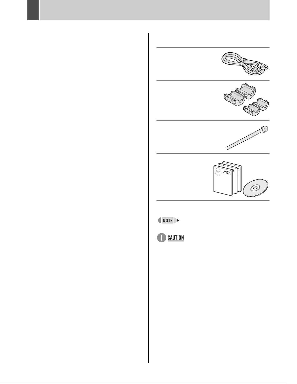
Accessories
Check that you have all the parts shown below.
Power cord
Core clamp
1 large, 1 small
z Large core clamp
For LAN cable
z Small core clamp
For RS-485 cable
Power cord tie
z Instruction Manual (DVR)
z Manual for Remote
Operation by
Network
Connection
z Quick Guide
z CD-ROM Manual
Symbols used in this manual
Information describing operation methods
or how to get the most out of functions.
Information describing the correct use of
the digital video recorder.
(JP. xx) indicates the page to be referred to.
Two-level security lock function - lets you
restrict users for data and equipment
management. (JP.89)
Expandable, can be connected to a PC
z Recorded video can be copied to CompactFlash
cards and CD-R/RW.
z A built-in LAN terminal provides support for network
control, thus facilitating live monitoring, camera
control, playback, searches, and menu setting.
z
Monitoring can be carried out on two different monitor
screens - namely, the main monitor and monitor 2. In
addition, the main monitor can be viewed in splitscreen mode while the monitor 2 is used for full
screen viewing or automatic camera selection.
z Dome cameras can be controlled by button
operations on the digital video recorder.
z Images stored on a CompactFlash card can be
printed directly from a printer.
Copyright
z This manual and software are copyrighted by Sanyo
Electric Co., Ltd.
z Brand and product names used in this manual are the
trademarks or registered trademarks of their respective
companies.
Except for personal use, copyright law prohibits the use of
recorded copyrighted images without the permission of the
copyright holder.
2 English
Page 4

CONTENTS
INTRODUCTION
1 BEFORE USE .................................................5
Notes on handling the internal HDD ...............5
Notes on installation locations ........................5
The hard disk and cooling fan are consumable
components. ...................................................6
Important recordings .......................................6
Protection of the hard disk ..............................6
Backup battery ................................................6
2 NAMES AND FUNCTIONS OF PARTS .........7
Front panel ......................................................7
Rear panel ....................................................10
OPERATION
1 PREPARING FOR USE ................................15
Operation display area ..................................15
Changing the position of the operation
display area ...................................................16
Changing the language .................................16
Setting the time .............................................17
The internal hard disk ...................................18
2 VIEWING VIDEO FROM A CAMERA ..........19
Viewing on a full screen ................................19
Viewing on quad screens ..............................19
Viewing on multi screens
(9 screens/ 16 screens) ................................20
Viewing on plus screen .................................20
Viewing with automatic screen selection ......21
Viewing on the monitor 2 ..............................21
3 INSTALLATION AND CONNECTIONS ...... 11
Basic connections ........................................ 11
Connecting RS-485 terminals ...................... 11
Connecting SANYO protocol devices
(Dome Cameras) .......................................... 13
Connecting an amplifier ............................... 13
Connecting ALARM IN terminals ................. 13
Connecting SENSOR ALARM OUT
terminals ....................................................... 14
Connecting CONTROL terminals ................. 14
Connecting the power cord .......................... 14
5 SEARCHING FOR RECORDED VIDEO ..... 30
Alarm search ................................................ 31
Alarm thumbnail search ............................... 32
Time/date search ......................................... 32
Archive area search ..................................... 34
Motion detection search ............................... 34
6
SAVING (COPYING) RECORDED VIDEO
Copying video to the hard disk’s
archive area ................................................. 39
Copying video to a CompactFlash card or
Microdrive ..................................................... 41
Printing images from CompactFlash cards
(quick print) .................................................. 43
Copying video to CD-R/RW ......................... 45
..... 38
3 RECORDING ................................................23
Normal recording ..........................................23
Timer recording .............................................23
Alarm recording .............................................24
Pre-alarm recording ......................................25
4 PLAYBACK ..................................................26
Playing video on a full screen .......................26
Fast-forward and fast-rewind playback .........26
Changing the playback speed .......................27
Enlarging the playback video ........................27
Viewing still images .......................................28
Performing frame advance
(forward or reverse) ......................................29
Playing video on multiple screens .................29
English 3
Page 5

CONTENTS
SETTINGS
1 MENU CONFIGURATION AND
OPERATIONS ..............................................47
Basic menu operations .................................47
Restoring menu setting items to
their default values ........................................48
Sub-menu configuration ................................49
2 INITIAL SET .................................................51
Initial settings ................................................51
Setting the time .............................................51
Setting the daylight saving ............................51
External clock setting ....................................53
Detecting connected cameras ......................54
Setting camera titles .....................................55
Setting holidays .............................................56
Setting time periods ......................................57
3 RECORD SET ..............................................60
Settings for recording ....................................60
Normal recording easy setup ........................60
Displaying the recording areas .....................64
Changing recording areas .............................65
Setting overwrite permission .........................66
Setting recording conditions ..........................67
Setting series recording ................................69
Setting auto deleting .....................................71
Setting normal recording ...............................71
Setting program recording ............................73
Timer settings ...............................................74
Setting alarm recording .................................77
Setting the motion sensors ...........................81
Setting alarm operation and display ..............84
Canceling alarms ..........................................85
4 GENERAL SET ............................................ 86
General settings ........................................... 86
Setting data display ...................................... 86
Setting display for video loss ........................ 87
Setting the buzzer ........................................ 88
Setting the security lock ............................... 89
Setting and initializing the hard disk ............. 92
Expanding the hard disk capacity ................ 93
Network settings ........................................... 93
Setting RS-485 ............................................. 96
Setting camera control ................................. 97
5 SCREEN SET ............................................ 100
Setting quad, multi 9 and 16 display .......... 100
Setting the period and monitors for
automatic screen selection ......................... 102
Setting masks ............................................. 104
Setting the color level ................................. 105
6 POWER LOSS/USED TIME ...................... 107
7 INITIALIZATION LOG ............................... 108
8 COPY MENU SETTINGS .......................... 109
Saving menu settings on a
CompactFlash card .................................... 109
Loading settings from a
CompactFlash card .................................... 110
OPERATIONINTRODUCTION SETTINGS OTHER
OTHER
1 INTERFACE SPECIFICATIONS ................111
RS-485 specifications .................................111
SANYO protocol command table ................112
2 SPECIFICATIONS ......................................113
Specifications ..............................................113
Dimensions .................................................114
UL disclaimer statement .............................114
Table of recording rate and times ...............115
Table of recording rate settings ..................117
Table of pre-alarm recording times .............118
Terminal board specifications .....................119
3 MENU SETTING SEQUENCE ................... 121
INDEX .............................................................. 123
4 English
Page 6

1 BEFORE USE
Notes on handling the internal HDD
This digital video recorder uses an internal hard disk drive
(HDD).
Be sure to observe the following points carefully when
operating, setting-up, or servicing the digital video
recorder.
Do not subject the digital video recorder to
sudden impact or vibration.
If the digital video recorder is subjected to sudden impact
or vibration, it may damage the HDD or cause corruption of
the data stored within it.
z Do not move the digital video recorder while the power
is turned on. Always ensure that the power is turned off
before removing the digital video recorder from or
placing it in a rack.
z When transporting the digital video recorder, pack it
securely using the specified materials. In addition,
choose a method of transportation that minimizes
vibration.
z When placing the digital video recorder on the floor or
another similar surface, attach the specified pads to its
base and place it down gently.
Do not move the digital video recorder for 30
seconds after turning off the power.
After the power is turned off, the disk inside the HDD will
continue to spin for a brief period due to inertia, and the
heads will be in an unstable condition.
During this period, the digital video recorder is even more
susceptible to damage from sudden impact and vibration
than when it is turned on. Make sure that the digital video
recorder is not subjected to even gentle vibration for at
least 30 seconds after turning off the power.
Do not operate the digital video recorder when
condensation has formed on it.
If the digital video recorder is operated in this type of
condition, there is a possibility that it will be permanently
damaged.
If the temperature around the digital video recorder
changes suddenly, wait for it to stabilize before operating
the digital video recorder.
Notes on replacing the HDD
Be sure to follow the correct procedure when replacing the
HDD.
z HDDs that have been removed from their packing may
not operate correctly if they are subjected to sudden
impact or vibration. It is recommended that you place
the HDD on a soft, level surface with the printed circuit
board facing upward after it has been unpacked.
z Take care to avoid subjecting the HDD to sudden
impact or vibration when removing and tightening
screws as part of the HDD replacement procedure.
Tighten all screws securely to ensure that they do not
loosen.
z The HDD is sensitive to static electricity; accordingly,
you should take the appropriate precautions to prevent
the buildup of static charges.
Handling a detached HDD unit
If transporting or storing the HDD unit in a detached condition,
be sure to first of all pack it using the specified materials.
In addition, choose a method of transportation that
minimizes vibration.
Notes on installation locations
The hard disk is sensitive to dust, sudden impact, and
vibration; furthermore, it should not be used near magnetic
objects. The following precautions should be observed in
order to prevent the loss of recorded data:
z Do not subject the digital video recorder to sudden
impact.
z Do not use the digital video recorder on a vibrating or
unstable surface.
z Do not disconnect the power plug from the wall outlet
during recording or playback.
z
Do not use the digital video recorder in areas with extreme
temperature changes (i.e., 10ºC or more per hour).
z Condensation may occur if the digital video recorder is
moved to an area with a significantly different
temperature or high humidity. If the digital video
recorder is used while condensation is present inside it,
operating problems may occur.
z Do not install the digital video recorder inside motor
vehicles, trains, or other areas under constant vibration.
z The digital video recorder has ventilation holes on its
left, rear, and bottom panels. Ensure that these holes
are not blocked after installation.
z Do not use the digital video recorder in a bookshelf,
box, or any other area with poor ventilation.
z This digital video recorder is designed for use in a
horizontal orientation, and vertical setup may result in
malfunction.
z When installing the digital video recorder in a rack,
ensure that a gap of at least 5 cm is provided at the top
and bottom.
English 5
Page 7

BEFORE USE1
The hard disk and cooling fan are
consumable components.
If used in an ambient temperature of 25ºC, the hard disk
should generally be replaced after 2 years; and the cooling
fan after 3 years. These figures are intended as a general
guideline only and should not be taken as a guarantee of
component performance.
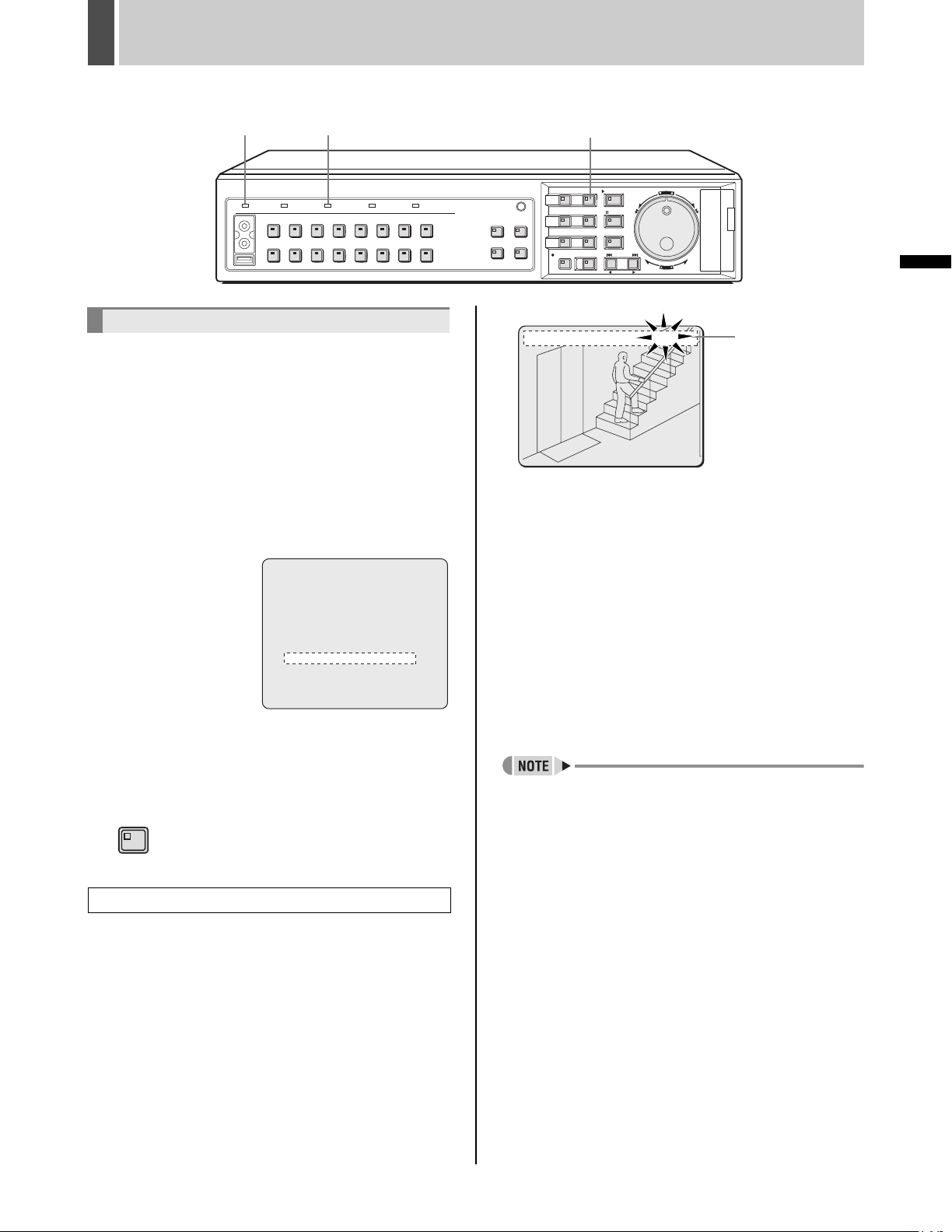
The POWER indicator will flash if a problem occurs with
the hard disk or fan. (JP.7)
Important recordings
z Always perform test recording in advance to confirm
whether the digital video recorder’s playback is normal.
z Note that Sanyo will accept no responsibility for losses
occurring as a result of recording or playback problems
caused by malfunction of this digital video recorder or
any connected devices.
z As a precaution against malfunction or accidents, it is
advisable to periodically back up important recordings
or to perform mirroring.
Protection of the hard disk
The hard disk is checked automatically when the power is
turned on. If an abnormality is detected, the POWER
indicator will begin to flash or an error message will be
displayed. If you need initialize the hard disk or to save
images stored on it, contact the dealer from whom you
purchased this digital video recorder.
INTRODUCTION
Backup battery
The digital video recorder comes with a built-in lithium
battery. If power is supplied continuously for at least 48
hours after setting the date and time, the clock will
continue to operate normally for up to 30 days without a
supply of power.
When disposing of this digital video recorder, contact the
dealer from whom it was purchased for information on how
to dispose of the lithium battery.
6 English
Page 8
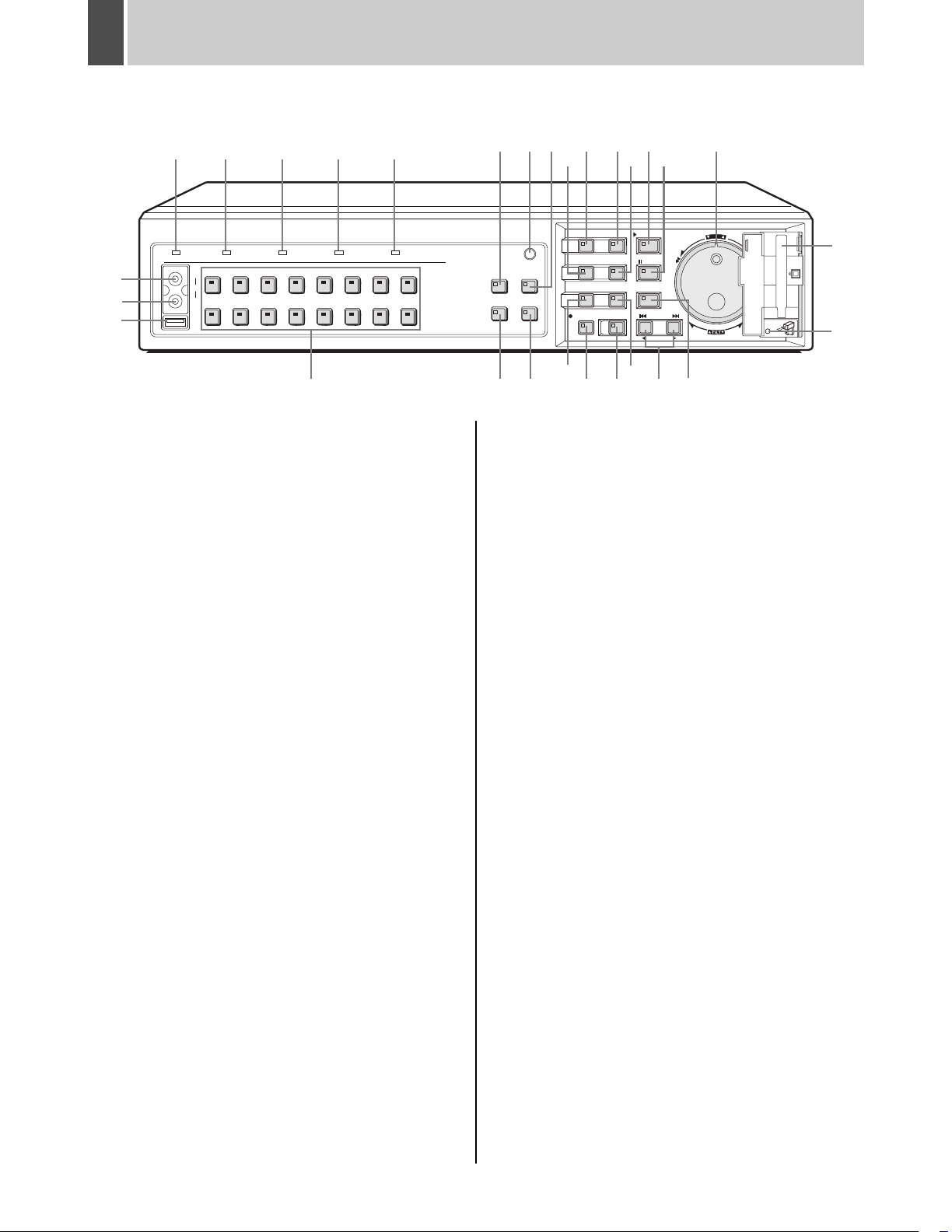
2 NAMES AND FUNCTIONS OF PARTS
DSR-3716
FUNC.
MULTI
AUTO PAN
PLUSMON 2
TOUR
9
12 13 14
MENU
MENU
ZOOM
SEQUENCE
REC/STOP
1615 17
EXIT/OSD
ENTER AF
SEARCH
COPY
SHUTTLE HOLD
TIMER
PLAY/STOP
STILL
IRIS
FOCUS
ALARM
ZOOM/I/FO
27
28
29
1
POWER FULL ALARM FULL LOCK ALARM
2345
AUDIO
OUT
VIDEO
USB
45
12 13
678123
14 15
8 7
QUAD
1691011
PRESET
SEQUENCE
24
SHUTTLE
JOG
E
N
T
R
A
E
L
C
E
R
CARD
MENU
MENU
RESET
PAN
EJECT
25
26
6
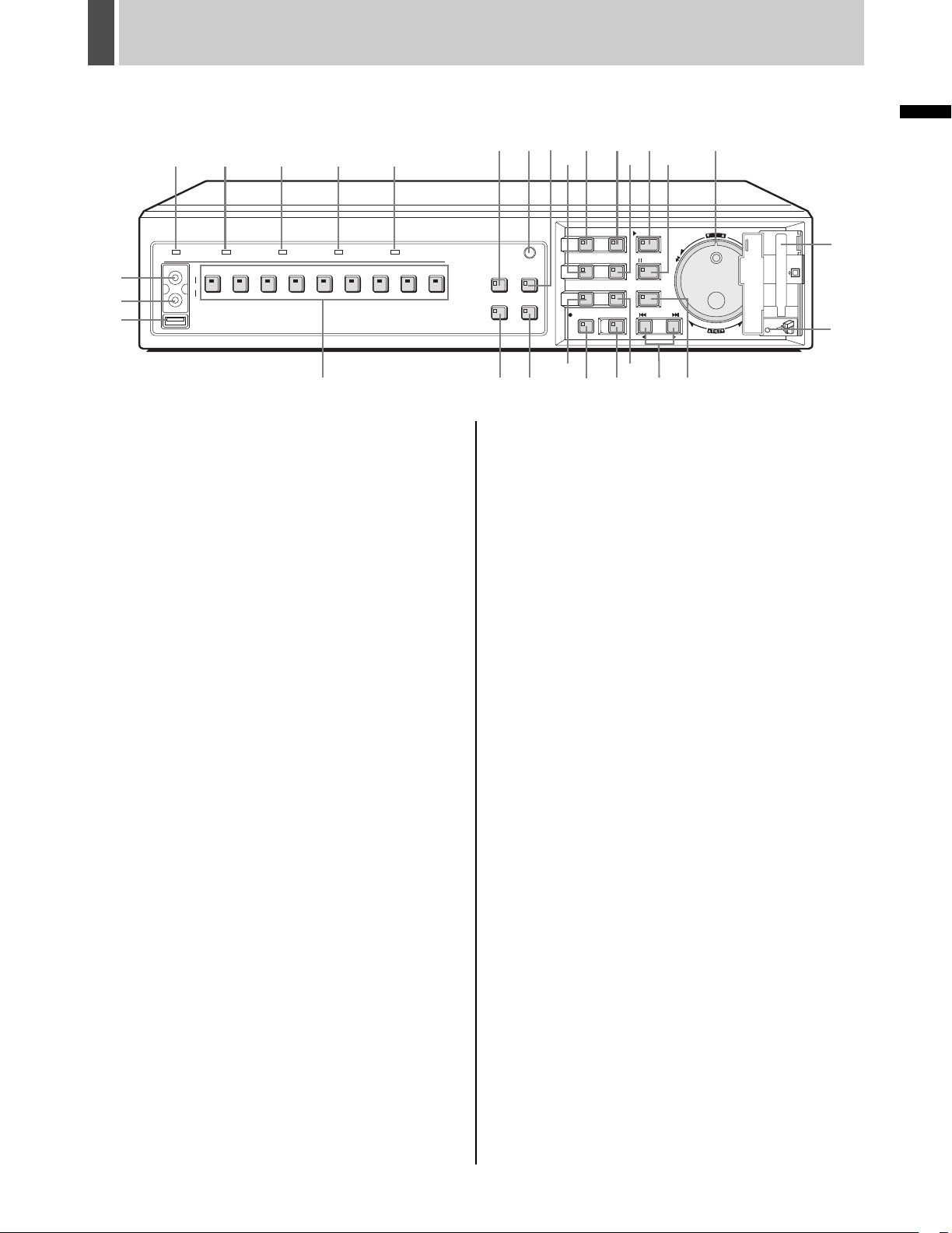
Front panel
1. POWER indicator
The POWER indicator will light up when the power is
turned on.
If the internal HDD or fan begins to malfunction, this
indicator will be flashed.
2. FULL indicator (JP.68)
The FULL indicator will begin to flash when the amount of
available memory in the hard disk’s normal recording area
drops to the percentage specified using menu settings.
In addition, recording will stop automatically when no more
memory is available, and the FULL indicator will switch to
a permanently lit condition.
This indicator can then be turned off by performing “AREA
FULL RESET” using menu settings.
3. ALARM FULL indicator (JP.68)
The ALARM FULL indicator will begin to flash when the
amount of available memory in the hard disk’s alarm
recording area drops to the percentage specified using
menu settings.
In addition, recording will stop automatically when no more
memory is available, and the ALARM FULL indicator will
switch to a permanently lit condition.
This indicator can then be turned off by performing “AREA
FULL RESET” using menu settings.
4. LOCK indicator (JP.91)
The LOCK indicator lights up when operation has been
locked using <SECURITY LOCK SET>.
An alarm will be sounded if a button is pressed in this
condition. In addition, a password entry screen will be
displayed on the monitor at this time.
If the correct administrator password is entered, the lock
condition will be cancelled and the LOCK indicator will turn
off.
5. ALARM indicator
The ALARM indicator flashes during alarm recording, and
it is lit up during pre-alarm recording.
10 11
18
22 23 20
21
19
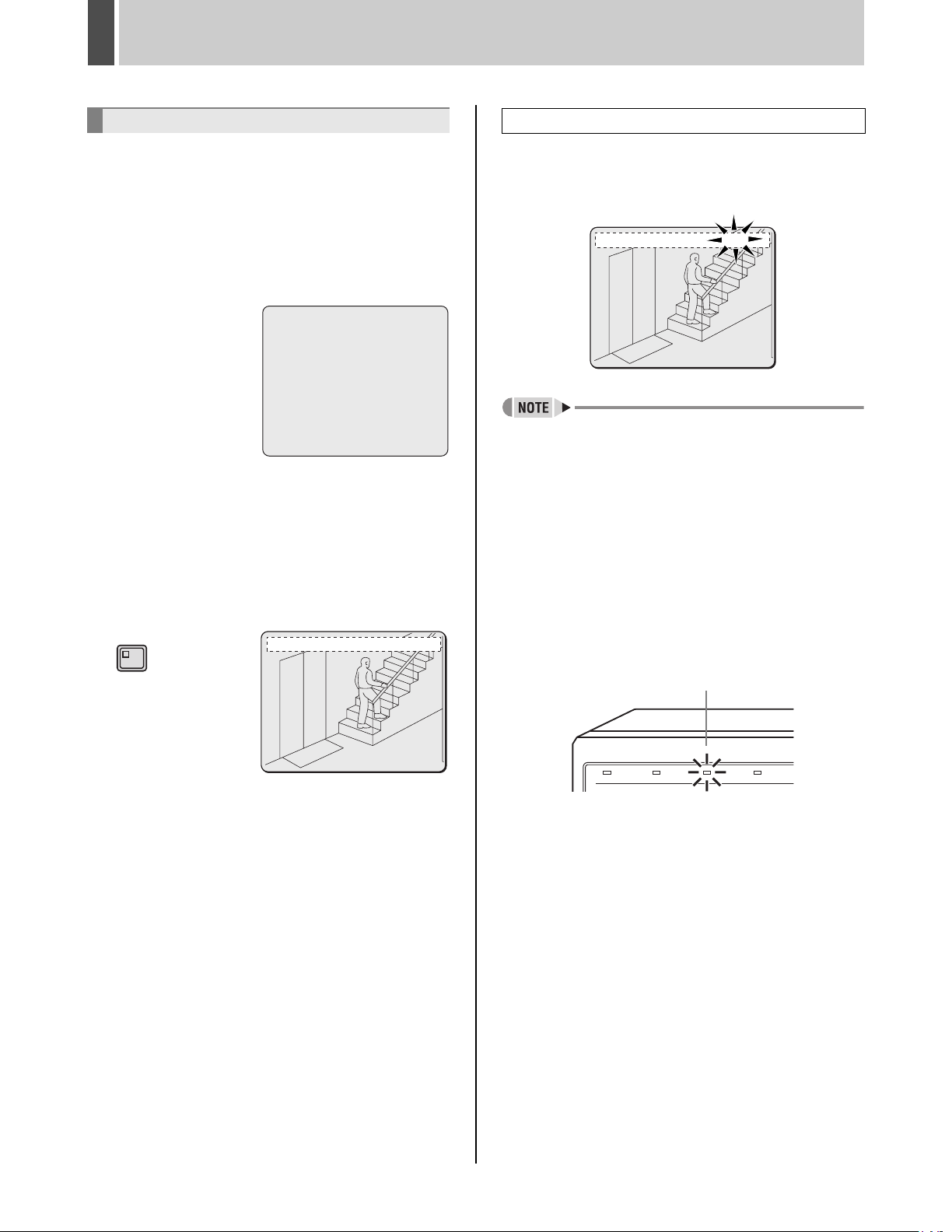
6. [CAMERA SELECT] buttons and indicators
When one or more cameras have been connected to the
VIDEO IN terminals on the digital video recorder’s rear
panel and the appropriate [CAMERA SELECT] button is
pressed, the corresponding indicator lights up and the
video feed from that camera is displayed on-screen.
z During quad, multi 9 or 16 screen display:
The indicators corresponding to the cameras being
displayed on the monitor are lit up.
z If video is lost:
The indicator starts to flash.
z If an alarm occurs:
The indicator for the corresponding camera starts to flash.
7. [FUNC.] button and indicator (JP.99)
Switch to normal mode or camera control mode.
Press button for camera control mode and indicator will
light. Press button again to return to normal mode.
Indicator turns off.
8. [QUAD] button and indicator (JP.19)
The [QUAD] button is used to display video in quad
screens, and the indicator will light up when this type of
display is being presented.
The QUAD indicator will turn off when a different screen
display mode is adopted.
9. [MULTI] button and indicator (JP.20)
The [MULTI] button is used to display video in multi 9 or 16
screens, and the indicator will light up when this type of
display is being presented.
The MULTI indicator will turn off when a different screen
display mode is adopted.
The DSR-3709 can only display video in nine screens.
10. [MON2] button and indicator (JP.21)
If the [MON2] button is pressed while a monitor is
connected to the MON2 output terminal on the rear panel,
it will be possible to change the monitor 2 output video.
The [CAMERA SELECT] and [SEQUENCE] buttons can
be used, and the indicator will be lit up during the setting
procedure.
English 7
Page 9
NAMES AND FUNCTIONS OF PARTS2
DSR-3709
1
POWER FULL ALARM FULL LOCK ALARM
27
28
29
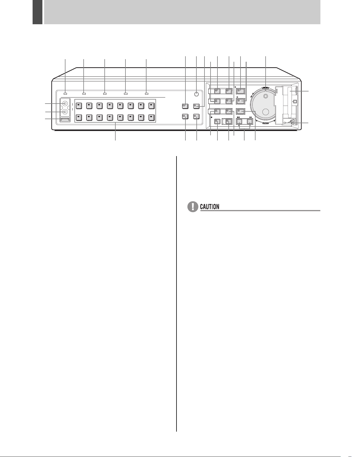
11. [PLUS] button and indicator (JP.20)
The [PLUS] button is used to enlarge video from a single
camera to quad screen size during multi 9 or multi 16
screen display.
For DSR-3709, this operation is available only when in
multi 9 screen display.
12. [MENU] button and indicator
The [MENU] button is used to display the menu screens
(i.e., setting screens), and the indicator lights up while any
of these screens is being displayed.
13. [EXIT/OSD] button and indicator
z EXIT
The [EXIT/OSD] button is used to exit the main menu or a
sub-menu. When a menu is displayed, the indicator turns
off; when the menu is closed and the normal display is
restored, the indicator lights up.
z OSD (JP.16)
Each time the [EXIT/OSD] button is pressed while the
digital video recorder is recording, playing, or stopped, the
operating display location moves in the order of top of
screen, bottom of screen, to hidden; furthermore, the
indicator lights up when this information is being displayed.
14. [PLAY/STOP] button and indicator (JP.26)
When the [PLAY/STOP] button is pressed, a recording
from the normal recording area or alarm recording area is
played and the indicator lights up. When pressed during
playback, this button stops the digital video recorder.
15. [ZOOM] button and indicator (JP.19, 27)
When the [ZOOM] button is pressed during monitoring or
playback on a full screen, a portion of the playback video is
magnified and the indicator lights up.
2345
AUDIO
OUT
VIDEO
USB
45
6 7 8 9123
6
8 7
12 13 14
9
24
1615 17
SHUTTLE
JOG
E
N
T
R
A
E
L
C
E
R
CARDCARD
CARD
MENU
MENU
RESET
RESET
EJECT
PAN
EJECT
QUAD
PRESET
SEQUENCE
10 11
FUNC.
MULTI
AUTO PAN
PLUSMON 2
TOUR
MENU
EXIT/OSD
PLAY/STOP
MENU
ENTER AF
ZOOM
SEARCH
STILL
COPY
TIMER
IRIS
SHUTTLE HOLD
FOCUS
19
SEQUENCE
REC/STOP
18
21 22 23 20
ALARM
ZOOM/I/FO
17. [STILL] button and indicator (JP.28)
When the [STILL] button is pressed during playback, the
current frame is displayed as a still image and the indicator
lights up. Playback can be resumed by pressing this button
once again.
18. [SEQUENCE] button and indicator (JP.21)
The [SEQUENCE] button can be pressed during
monitoring to automatically switch between screen display.
When pressed, the indicator begins flashing and the
display is changed automatically. The lighting condition of
CAMERA SELECT indicators also changes in response to
the screen display.
19. [COPY] button and indicator (JP.39)
The [COPY] button is used to copy recorded video to the
hard disk’s archive area, to a CompactFlash card, CD-R/
RW or to a Microdrive.
The indicator lights up during the copy process.
20. [SHUTTLE HOLD] button and indicator (JP.26)
The [SHUTTLE HOLD] button is used to lock shuttle dial
operation for a constant speed of playback or slow playback.
The indicator lights up while the shuttle dial is locked.
When a password has been set, furthermore, this button
can be pressed for at least three seconds to activate the
security lock.
21. [REC/STOP] button and indicator (JP.23)
The [REC/STOP] button is pressed to start normal
recording, and the indicator lights up during this process.
Furthermore, pressing this button for at least three
seconds stops recording and turns off the indicator.
INTRODUCTION
25
26
16. [SEARCH] button and indicator (JP.31)
When the [SEARCH] button is pressed while the digital
video recorder is recording or stopped, the search menu is
displayed and the indicator lights up. The search menu
can be closed by pressing this button once again.
8 English
Page 10
NAMES AND FUNCTIONS OF PARTS2
DSR-3716
POWER FULL ALARM FULL LOCK ALARM
27
28
29
FUNC.
MULTI
AUTO PAN
PLUSMON 2
TOUR
9
12 13 14
MENU
MENU
ZOOM
SEQUENCE
REC/STOP
1615 17
EXIT/OSD
ENTER AF
SEARCH
COPY
SHUTTLE HOLD
TIMER
PLAY/STOP
STILL
IRIS
FOCUS
ALARM
ZOOM/I/FO
24
SHUTTLE
JOG
E
N
T
R
A
E
L
C
E
R
CARD
MENU
MENU
RESET
PAN
EJECT
25
26
1
2345
AUDIO
OUT
VIDEO
USB
45
12 13
678123
14 15
1691011
8 7
QUAD
PRESET
SEQUENCE
6
22. [TIMER] button and indicator (JP.23)
If the [TIMER] button is pressed while the recording is
stopped, timer recording standby mode is adopted and
recording will then start automatically at the set time. The
indicator will be lit up while in timer recording standby
mode or timer recording.
If the button is pressed during timer recording, this process
is stopped and the indicator turns off. Furthermore, if the
[TIMER] button is pressed when in timer recording standby
mode, indicator is turned off and timer recording is
cancelled.
23. [ALARM] buttons (JP.31)
When an [ALARM] button is pressed during playback or
still, the digital video recorder skips to the next earlier or
next later alarm.
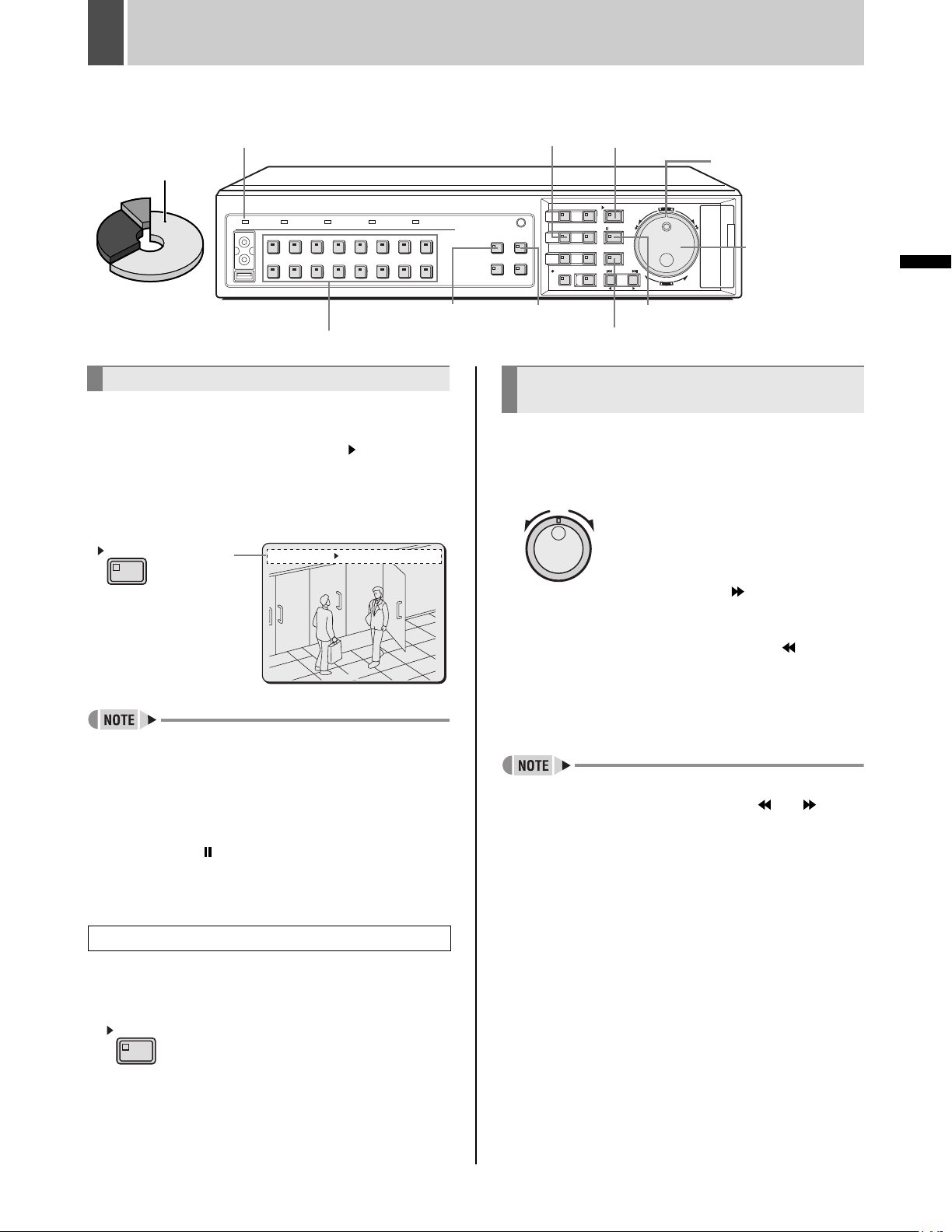
24. Jog dial (inside) and shuttle dial (outside)
z During playback:
Use the jog dial to change the playback speed.
Use the shuttle dial to perform fast-forward or fastreverse playback.
z During menu display:
Use the jog dial to move the cursor and to change
setting values. Use the shuttle dial to confirm settings.
10 11
18
22 23 20
21
19
28. Video output terminal
This terminal outputs the same video as that of the MAIN
MONITOR output terminal on the rear panel.
29. USB terminal (JP.45)
This terminal connects to a recordable CD-R/RW drive.
z The USB terminal is for the use of the recommended
Sanyo CD-R/RW drive (sold separately). Nonrecommended peripherals cannot be connected.
z For recommended recordable drives, check the Sanyo
homepage or ask at your local Sanyo dealer.
Sanyo website URL:
http://www.sanyosecurity.com
25. CompactFlash card slot (JP.41)
This slot is used to house a CompactFlash card or Microdrive.
26. [MENU RESET] button (JP.48)
The [MENU RESET] button is used to default menu
settings.
When setting motion sensors, furthermore, all sensors on
the same line as the cursor can be turned on
simultaneously by pressing this button.
27. Audio output terminal
Audio output is the same as that of the rear panel AUDIO
OUT terminal.
English 9
Page 11
NAMES AND FUNCTIONS OF PARTS2
DSR-3716
(The number of terminals for the DSR-3709 may differ. For more details, see below.)
2 3 4 5 6 7 8 9 10 11 12 13 14 15
1
1
IN
2
OUT
ALL
RESET
AUDIO
IN OUT
MIC IN
MONITOR OUT
MAIN
MON2
LAN
USB
3 15
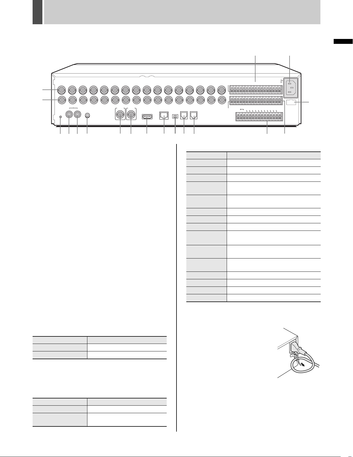
Rear panel
1. VIDEO IN terminals
The DSR-3709 has nine VIDEO IN terminals.
2. VIDEO OUT terminals
The DSR-3709 has nine VIDEO OUT terminals.
3. [ALL RESET] button
When the [ALL RESET] button is pressed, the digital video
recorder is reset and the time is returned to its default
setting.
4. AUDIO IN terminal
5. AUDIO OUT terminal
6. MIC IN terminal
7. MAIN MONITOR output terminal
8. MON2 output terminal
9. USB terminal
This terminal connects to a recordable CD-R/RW drive.
10. LAN terminal (10 Base-T or 100 Base-TX)
11. RS-485 termination switch
12. RS-485 terminal (A)
13. RS-485 terminal (B)
14. ALARM IN terminals
These terminals are used to activate alarm recording in
response to operation of an alarm switch on a connected
device.
The DSR-3709 has nine ALARM IN terminals.
Pin Signal
C Ground
ALARM IN 1 to 16 Alarm input No. 1 through No. 16
RS-485
A RS-485 B
TERMINATE
OFF ON
DO NOT CONNECT TO PHONE LINE
12
11
13
16. CONTROL terminals
C Ground
REMOTE R1 Remote input 1
REMOTE R2 Remote input 2
CLOCK SET IN
CLOCK SET OUT
ALARM OUT Total alarm output
ALARM RESET Alarm reset input
WARNING OUT Output of an HDD or FAN malfunction error
FULL
ALARM FULL
SERIES IN
SERIES OUT Signal output to an analog series connection
EXT TIMER IN Signal input from an external timer
NON REC OUT Non-recording output
C Ground
17. Power socket (AC IN)
Insert the supplied power cable securely into this socket.
18. Power cord holder
Secure the power cord to the holder
using the cord tie (accessory) as
shown in the illustration.
16
Pin Signal
17
AC IN
NO
N RE
C O
UT
CR1 R2
ALARM IN
SENSOR
ALARM OUT
C
123456789
C
123456789
ALARM RESET
C
ALARM
LOCK OUT
C
LOCK IN
REMOTE
OUT
C
14
10 11 12 13 14 15 16
10 11 12 13 14 15 16
WARNING OUT
ALARM FU
FULL
CONTROL
SERIES IN
LL
SERIES OU
EXIT TIMER IN
T
169 1087654
Input of a clock setting signal from an
external device
Output of a clock setting signal to an
external device
Capacity warning output for normal
recording area space
Capacity warning output for alarm recording
area space
Signal input from an analog series
connection
INTRODUCTION
18
15. SENSOR ALARM OUT terminals
The terminals are used when motion sensors have been
set (JP.81) to output an alarm signal to a connected
device upon detection of motion.
The DSR-3709 has nine SENSOR ALARM OUT terminals.
Pin Signal
C Ground
SENSOR ALARM OUT
1 to 16
Output of an alarm signal for Camera
No. 1 through No. 16
10 English
Page 12
3 INSTALLATION AND CONNECTIONS
This section describes how to connect the digital video recorder to video cameras and other devices. Be sure to read the
instruction manuals for each connected device.
z Improper connections can result in malfunction or the
emission of smoke.
z A separate power supply is required for operation of
each camera.
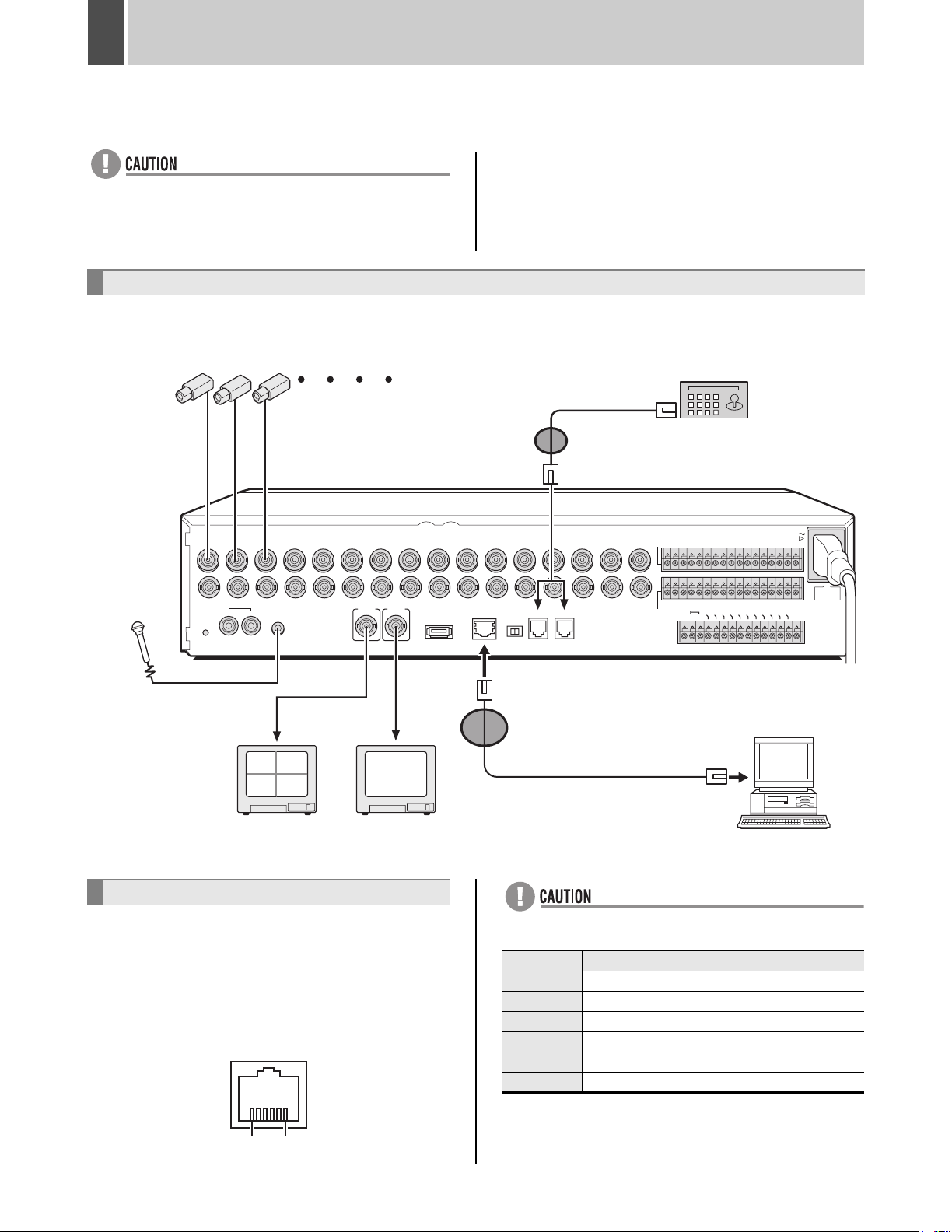
Basic connections
The following diagram shows the connections for cameras, monitors, a microphone, and a PC.
DSR-3716
The DSR-3709 can be connected to nine cameras.
Camera
(sold separately)
(1-16)
The RS-485 connector is
connected to A or B according
to the type of cable.
System controller (sold separately)
VSP-8000/9000
*2 Wrap the cable once around the
small core clamp to attach it.
1
2 3 4 5 6 7 8 9 10 11 12 13 14 15
IN
Microphone
(sold separately)
OUT
ALL
RESET
AUDIO
IN OUT
MIC IN
MONITOR OUT
MAIN
MON2
USB
Video input
Video input
terminal
terminal
0201
0403
Monitor
(sold separately)
Monitor 2
(sold separately)
Connecting RS-485 terminals
The RS-485 terminals are used to connect a system
controller (sold separately) to the digital video recorder.
After connecting the system controller, you will need to
carry out the settings that are given in the <RS-485 SET>
menu. (JP.96)
Pin locations
ALARM IN
C
RS-485
LAN
A RS-485 B
TERMINATE
OFF ON
DO NOT CONNECT TO PHONE LINE
16
C
SENSOR
ALARM OUT
123456789
123456789
CLOC
REMOTE
C
CLOC
K
I
N
K
OU
ALARM OUT
T
ALARM
10 11 12 13 14 15 16
10 11 12 13 14 15 16
WARNING OU
ALARM
F
RE
U
S
LL
ET
T
CONTROL
FULL
120 V-240 V AC
*1 Wrap the cable once around the
large core clamp to attach it.
* If the monitor 2 (MON2) is not synchronized
with the connected cameras, vertical
picture instability may occur upon the
switching of camera video.
z Do not connect to phone line.
Pin number Connector A signal Connector B signal
1 Not used Not used
2 Not used Not used
3A B
4B A
5 Not used Not used
6 Not used Not used
AC IN
E
SERIES OUT
NO
XIT TIMER
SERIES IN
N
REC
O
U
I
T
N
(50/60 Hz)
PC
CR1 R2
16
English 11
A: Non-inverting driver output/receiver input
B: lnverting driver output/receiver input
Page 13
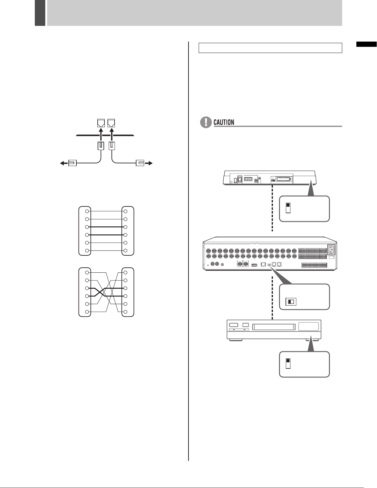
INSTALLATION AND CONNECTIONS3
Connection
The digital video recorder supports both straight type and
crossed type connection cables.
When using a straight type connection cable, connect the
RS-485 connector’s pin A to the pin A socket, or pin B to
the pin B socket.
When using a crossed type connection cable, connect the
RS-485 connector’s pin A to the pin B socket, or pin B to
the pin A socket.
BA
RS485
DO NOT CONNECT TO PHONE LINE
To other
connector A
To other
connector A
Straight type cable Crossed type cable
Cable types
Straight type:
1
2
3
4
5
6
Not used
Not used
Not used
Not used
1
2
3
4
5
6
RS-485 termination switch settings
When connecting multiple devices, you must make
termination settings on both end devices.
z Set the RS-485 termination switch of both end devices
to ON.
z Be sure to set the RS-485 termination switches of all
devices in between (devices other than the first and last
devices) to OFF.
z If you don’t make the correct termination settings, the
incorrect data will be transmitted to each device.
Example
System controller
ON
Termination
switch
OFF
INTRODUCTION
Crossed type:
1
2
3
4
5
6
Not used
Not used
Not used
Not used
1
2
3
4
5
Digital video recorder
OFF ON
RS-485
termination
switch
6
Time-lapse VCR
ON
Termination
switch
OFF
12 English
Page 14
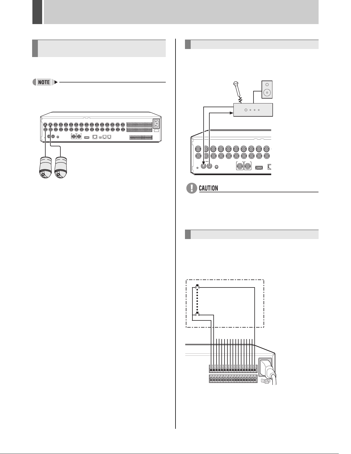
INSTALLATION AND CONNECTIONS3
Connecting SANYO protocol devices
(Dome Cameras)
Turn off all devices and use a coaxial cable to connect the
devices.
z Use the same procedure to connect using PELCO and
BBV.
Camera
1 Connect cameras to the VIDEO IN
terminals.
2 Set the protocols and address in the
<CAMERA CONTROL SET> screen.
(JP.97)
Connecting an amplifier
An amplifier is connected when using a microphone or
external speakers with the digital video recorder.
Audio input
Audio
output
AUDIO
IN OUT
OUT
IN
z Audio input from the AUDIO IN terminal and the MIC IN
terminal cannot be performed simultaneously. If both
terminals have devices connected, the MIC IN terminal
is used.
Amp
(sold separately)
Connecting ALARM IN terminals
3 Operate the dome cameras with the
front panel buttons. (JP.99)
When using external alarms (i.e., intruder sensors and the
like), external switches are to be connected to the ALARM
IN terminals.
16
Connecting ALARM IN
terminals to external
1
C
123456789
The DSR-3709 has nine ALARM IN terminals.
10 11 12 13 14 15 16
switches
English 13
Page 15
INSTALLATION AND CONNECTIONS3
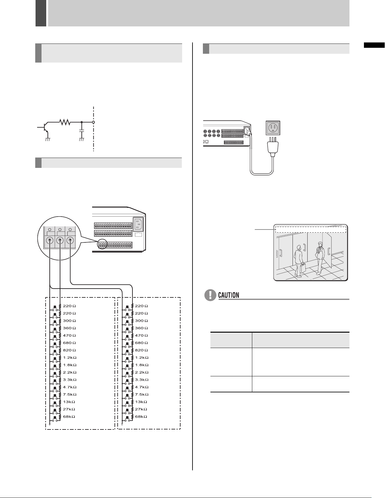
Connecting SENSOR ALARM OUT
terminals
The SENSOR ALARM OUT terminals are used to relay
alarm signals whenever one of the digital video recorder’s
motion sensors is triggered. Normally in an open condition,
a terminal adopts low condition when a sensor for the
corresponding camera number has been triggered.
1
Rating for each terminal
z Maximum current: 25 mA
z Maximum voltage: 25 V
Connecting CONTROL terminals
The connections for a remote control circuit are shown
below. This digital video recorder can be remotely controlled
when a remote-control circuit similar to that shown here is
connected to the remote-input control terminals.
Connecting the power cord
1 When you have finished making all the
other connections, make sure the
voltage is 120 V-240 V AC and insert the
power plug into the wall outlet.
There is no power switch. The display indicators flash, and after
a few moments, the monitor screen displays the camera image.
120 V-240 V AC
(50/60 Hz)
z When turning the power on for the first time
“PLEASE SET THE CLOCK” is displayed on the monitor
screen. Follow the procedures on P.17 to set the clock.
z If the clock is already set
The operation display area is displayed.
Operation
display area
01-01-04 00:00:00 REC REPEAT EN A ALARM 0000
0
INTRODUCTION
R1C R2
R1 R2
: Camera 1*: INDEX +
SW 1
: Camera 2*: INDEX -
SW 2
: Camera 3*:
SW 3
: Camera 4*: SEQUENCE
SW 4
: Camera 5*: MON2
SW 5
: Camera 6*: PLUS
SW 6
: Camera 7*: QUAD
SW 7
: Camera 8*: MULTI
SW 8
: Camera 9*:
SW 9
: Camera 10:
SW 10
: Camera 11: PAN left
SW 11
: Camera 12: PAN right
SW 12
: Camera 13: TILT down
SW 13
: Camera 14: TILT up
SW 14
: Camera 15: ZOOM wide
SW 15
: Camera 16: ZOOM tele
SW 16
(When operated
independently)
(When combined
with R2 Shift key)
AUTO FOCUS
MENU RESET
SW 17
: REC/STOP
SW 18
: PLAY/STOP
SW 19
: STILL
SW 20
: SEARCH
SW 21
:
SHIFT (Doubles with R1)
SW 22
: PLAY
SW 23
: REC
SW 24
: MENU
SW 25
: EXIT/OSD
SW 26
: +
SW 27
: -
SW 28
:
→
SW 29
:
←
SW 30
: ZOOM
SW 31
: COPY
SW 32
: TIMER
z Use a resistance of 1/10 ohms or more and with a D
ranking (Precision within ±0.5%).
z The remote control cable should be no more than 5 m
long.
* The DSR-3709 can operate up to nine cameras (*).
02
z If the POWER indicator starts flashing;
If a problem occurs during use, the POWER indicator
will begin to flash and an explanation will be displayed.
In these cases, contact a Sanyo service center.
POWER
indicator status
Four flashes per
second
One flash per
second
There is a problem with the hard disk. The
hard disk must be replaced or initialized.
Contact a Sanyo service center to recover
recorded images.
There is a problem with the fan.
Meaning
z The power cord’s ground terminal is not provided for
enhanced safety; rather, it can be used to reduce the
level of interference when the digital video recorder is
connected to analog devices.
If a large amount of noise is generated when the digital
video recorder is connected to analog devices, connect
this terminal to the building’s earth.
14 English
Page 16
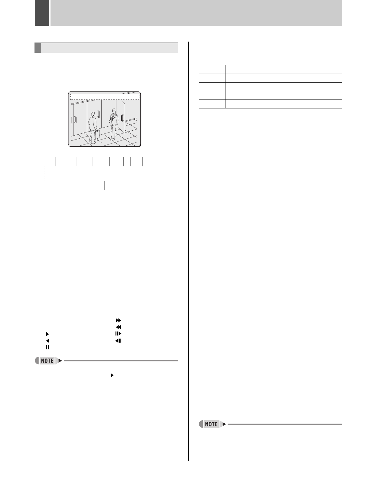
1 PREPARING FOR USE
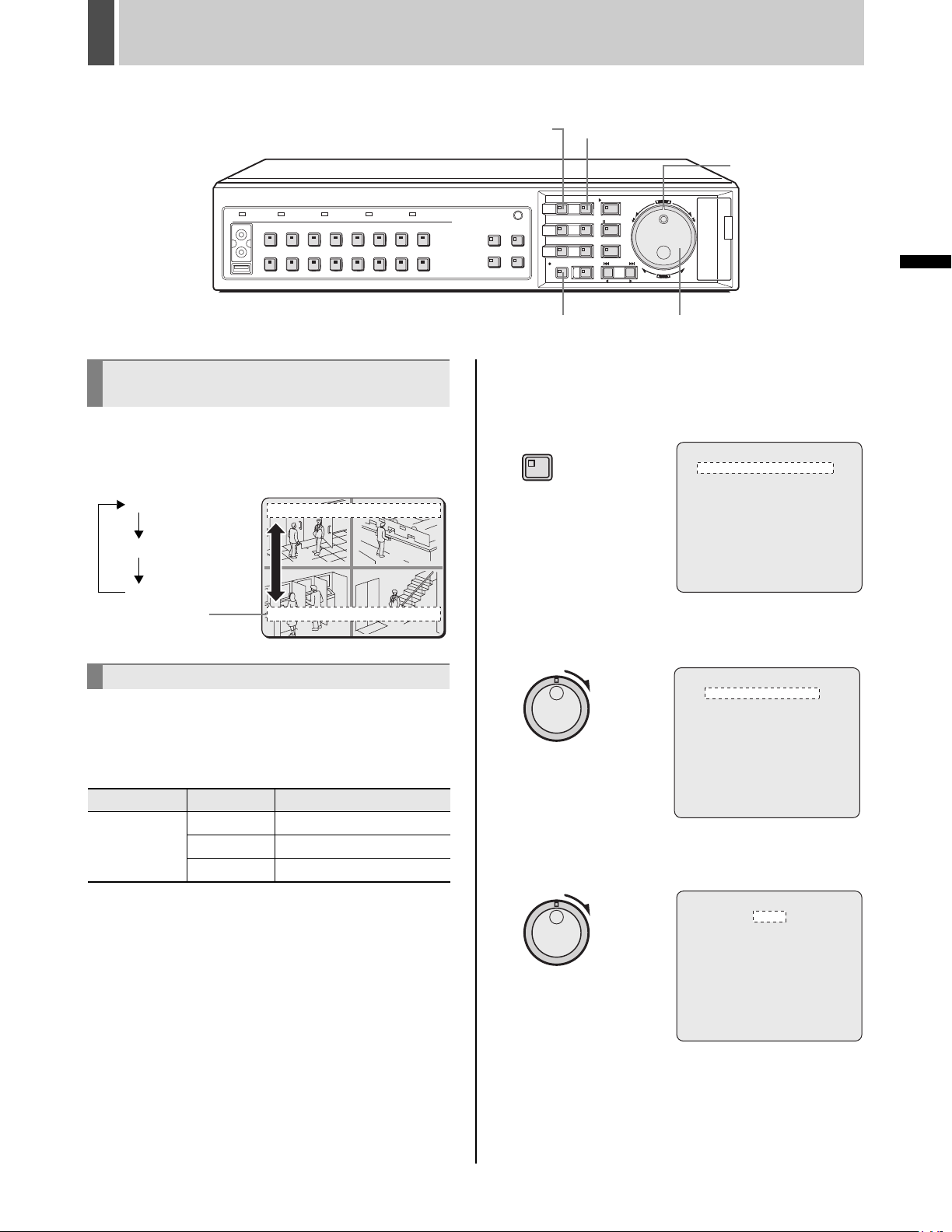
Operation display area
Whenever the power is turned on, the operation display
area will be shown at the top of the monitor screen. This
area indicates the date, time, picture quality, and other
information needed for operation.
01-01-04 00:00:00 REC REPEAT EN A ALARM 0000
02
(1) (2) (3) (4) (5)(6) (7)
01-01-04 00:00:00 REC REPEAT EN A ALARM 0000
02
(8)
(1) Date display (JP.17)
“01-01-04” (month-day-year) is displayed when you
turn the power on for the first time. Be sure to specify
the correct date using menu settings.
(2) Time display (JP.17)
“00:00:00” is displayed when you turn the power on for
the first time. The digital video recorder uses the date
and time to manage recording and playback points.
Accordingly, if the time has not been set correctly, you
will not be able to effectively search for video data.
Make sure to specify the time using menu settings.
Recording will not be possible until a setting has been
made.
(3) Operating symbol display
Displays the current operation (such as recording or
playback).
REC: Recording : Fast-forward playback
EXT: External timer recording : Fast-rewind playback
: Playback : Slow playback
: Reverse playback : Reverse slow playback
: Still
z During simultaneous recording and playback, the
display indicates playback ( ).
(4) Remaining memory in recording area (JP.67)
Displays the remaining area memory as a percentage
when overwriting in the normal recording area or the
alarm recording area is forbidden. If overwriting has
been permitted, “REPEAT” is displayed.
0
(5) Picture quality display (JP.71)
Displays the quality of the video that can be recorded
on the hard disk. Set to “EN” (Enhanced) by default.
BA Basic
NO Normal
EN Enhanced
FI Fine
SF Super Fine
(6) Audio recording display
“A” is displayed when audio is being recorded or
played back.
(7) Alarm display and alarm count display (JP.77)
When you set an alarm using the “ALARM REC
MODE SET” menu item, the alarm display area
presents the following information.
z When alarm recording is set;
“ALARM” is displayed.
“ALARM” is flashed during alarm recording.
z When pre-alarm recording is set;
“PRE” is displayed.
When an alarm occurs, “PRE” disappears,
“ALARM” is displayed, and the number of alarms is
shown. The total number is indicated in the alarm
display.
z When performing playback from the archive
area;
“ARCHIV” is displayed.
z When an external alarm signal is activated;
“EA” is flashed to the left of the camera number.
z When a motion sensor alarm signal is
activated;
“SA” is flashed to the left of the camera number.
z When an external alarm signal and motion
sensor signal are activated;
“ES” flashes to the left of the camera number.
(8) Camera title display
The camera number or camera title is displayed. In
addition, when an alarm occurs, the camera number
and alarm “EA”, “SA” or “ES” are displayed along with
the camera title.
z During video loss;
The display alternates between showing the
camera title and “VIDEO LOSS”. “VIDEO LOSS”
flashes when the operating display is hidden.
(JP.16)
z During no video signal;
“NO VIDEO” is displayed in place of the camera
title.
English 15
z Although operations such as playback, copying, and
data transfer are possible while recording, this unit
gives priority to recording, and other operations may be
delayed as a result.
Page 17
PREPARING FOR USE1
[MENU] button [EXIT/OSD] button
Shuttle dial
CARDCARD
MENU
RESET
EJECT
OPERATION
Changing the position of the
operation display area
1 Press the [EXIT/OSD] button.
As the [EXIT/OSD] button is pressed, the operation display
area moves to a different location or is hidden.
Top (default)
Bottom
Hidden
Operation
display area
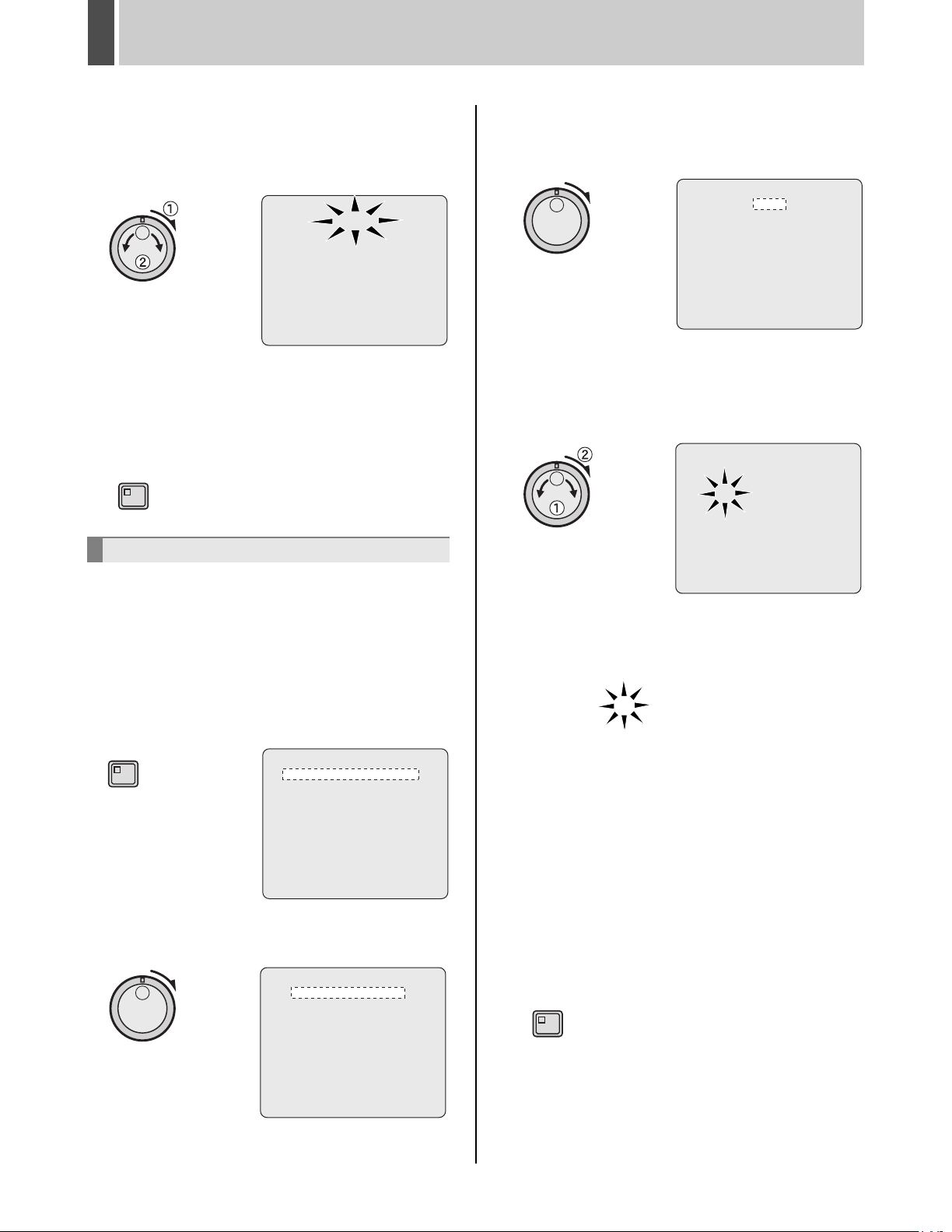
Changing the language
Use the following procedure to set the language displayed
on the monitor.
[Settings] ( indicates default setting)
01-01-04 00:00:00 REC REPEAT EN A ALARM 0000
01 02
01-01-04 00:00:00 REC REPEAT EN A ALARM 0000
03 04
[REC/STOP] button
Jog dial
1 Press the [MENU] button.
The MENU indicator lights up and the <MAIN MENU> is
displayed.
MENU
<MAIN MENU>
1.INITIAL SET ->
2.RECORD SET ->
3.GENERAL SET ->
4.SCREEN SET ->
5.POWER LOSS/USED TIME ->
6.INITIALIZATION LOG ->
7.COPY MENU SETTINGS ->
MOVE:JOG SELECT:SHUTTLE
2 Turn the shuttle dial clockwise.
The <INITIAL SET> screen is displayed.
<INITIAL SET>
1.LANGUAGE/CLOCK SET ->
2.CAMERA DETECT ->
3.TITLE SET ->
4.HOLIDAY SET ->
5.TIME PERIOD SET ->
Item Setting Description
ENGLISH Sets the language to English.
LANGUAGE
FRANCAIS Sets the language to French.
ESPAÑOL Sets the language to Spanish.
MOVE:JOG SELECT:SHUTTLE
3 Turn the shuttle dial clockwise.
The cursor moves to “ENGLISH”.
<LANGUAGE/LANGUE/IDIOMA>
ENGLISH
<CLOCK SET>
01-01-2004 THU 00:00:00
<DAYLIGHT SAVING>
MODE : USE
WEEK MONTH TIME
ON 1ST-SUN 04 02:00
OFF LST-SUN 10 02:00
<EXT.CLOCK SET>
ADJUST. TIME 01:00
16 English
Page 18
PREPARING FOR USE1
4 Turn the shuttle dial clockwise, and
then turn the jog dial to select the
desired language.
The set item flashes.
<REGL.LANGUE>
FRANCAIS
<REGL.HORLOGE>
01-01-2004 JEU 00:00:00
<HEURE D
MODE : MARCHE
SEMAINE MOIS HEURE
ON 1ER-DIM 04 02:00
OFF DER-DIM 10 02:00
<REGL.HORLOGE EXTERNE>
REGL.DE L
,
ETE>
,
HEURE 01:00
5 When you have made a selection, turn
the shuttle dial clockwise.
The cursor moves to the date and time.
The language has now been set.
To return to the normal screen, press the [EXIT/OSD] button.
EXIT/OSD
Setting the time
(Default: 01-01-2004 THU 00:00:00)
Be sure to set the correct date and time as these settings
are used during recording and searching.
Example: Setting 8:30 on October 26, 2004
1 Press the [MENU] button.
The MENU indicator lights up and the <MAIN MENU> is
displayed.
MENU
<MAIN MENU>
1.INITIAL SET ->
2.RECORD SET ->
3.GENERAL SET ->
4.SCREEN SET ->
5.POWER LOSS/USED TIME ->
6.INITIALIZATION LOG ->
7.COPY MENU SETTINGS ->
MOVE:JOG SELECT:SHUTTLE
2 Turn the shuttle dial clockwise.
The <INITIAL SET> screen is displayed.
<INITIAL SET>
1.LANGUAGE/CLOCK SET ->
2.CAMERA DETECT ->
3.TITLE SET ->
4.HOLIDAY SET ->
5.TIME PERIOD SET ->
3 Turn the shuttle dial clockwise.
The <LANGUAGE/LANGUE/IDIOMA> screen is
displayed.
<LANGUAGE/LANGUE/IDIOMA>
ENGLISH
<CLOCK SET>
01-01-2004 THU 00:00:00
<DAYLIGHT SAVING>
MODE : USE
WEEK MONTH TIME
ON 1ST-SUN 04 02:00
OFF LST-SUN 10 02:00
<EXT.CLOCK SET>
ADJUST. TIME 01:00
4 Turn the jog dial to select the date and
time for <CLOCK SET> and turn the
shuttle dial clockwise.
“01” flashes (indicating the month).
<LANGUAGE/LANGUE/IDIOMA> K
ENGLISH
<CLOCK SET>
01-01-2004 THU 00:00:00
<DAYLIGHT SAVING>
MODE : USE
WEEK MONTH TIME
ON 1ST-SUN 04 02:00
OFF LST-SUN 10 02:00
<EXT.CLOCK SET>
ADJUST. TIME 01:00
5 Set “10” with the jog dial or numeric
keys and turn the shuttle dial clockwise.
“01” flashes (indicating the day).
10-01-2004 MON 00:00:00
6 Use the same procedure to set the day
(26), year (2004), hour (08), and minute
(30).
When you have set the minute, the cursor moves to
“MODE” under <DAYLIGHT SAVING>, and the clock
starts counting from 00 seconds.
z The week day is set automatically.
z The clock is stopped during date and time settings.
7 Press the [EXIT/OSD] button.
The setting procedure is ended and the display returns to
the normal screen.
EXIT/OSD
MOVE:JOG SELECT:SHUTTLE
English 17
Page 19
PREPARING FOR USE1
1%
80%
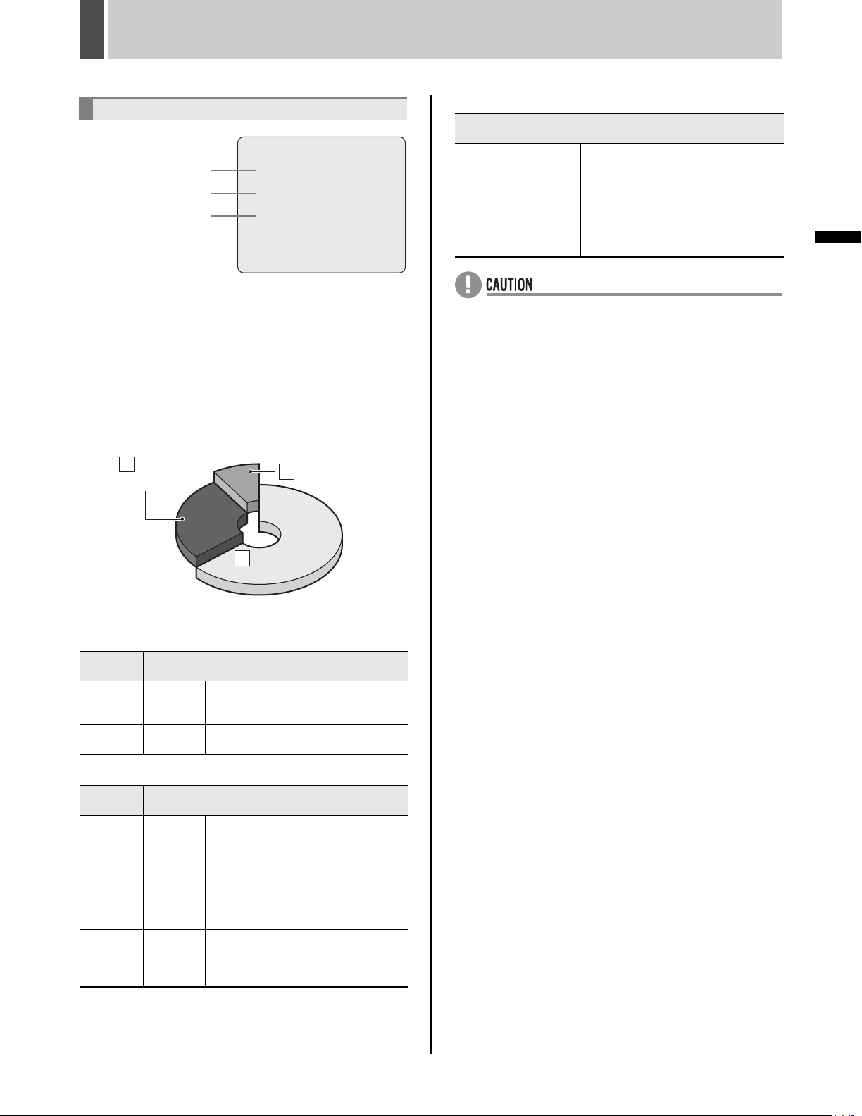
The internal hard disk
<RECORDING AREA SET>
[A]
[B]
[C]
Hard disk recording areas
When the digital video recorder is turned on, recording
areas are automatically setup within the internal hard disk
(with the default settings being normal recording area:
80%, alarm recording area: 19%, and archive area: 1%).
When the [REC/STOP] button is pressed, this digital video
recorder starts recording video data in the normal
recording area. When an alarm occurs, the corresponding
video data is recorded in the alarm recording area.
Alarm
B
recording
area
19%
TOTAL CAPACITY : 82GB
NORMAL RECORDING AREA : 80 %
AREA FULL RESET ->
ALARM RECORDING AREA : 19 %
AREA FULL RESET ->
ARCHIVE AREA : 1 %
AREA FULL RESET ->
CAUTION : WHEN THE AREA SETTING IS CHANGED,
THE WHOLE AREA WILL BE INITIALIZED !
Archive area
1%
1%
C
80%
80%
Normal recording
A
area
[C] Archive area
Recording
mode
Copy Manual
z If the memory allocations for the various hard disk
recording areas are changed during a recording
process, all stored recordings will be deleted and the
hard disk will be initialized; accordingly, special care
should be taken. For more details, refer to P.65.
z In the case of certain hard disks, error may be present
in the total hard disk capacity as displayed on menu
screens.
Recording method
This area is used to store important
video data copied from the normal
recording area and/or alarm recording
area. By making changes to the normal
recording area and the alarm recording
area, this area can be extended to up
to 10 GB in size (i.e., 12% when using
a 80 GB hard disk).
OPERATION
Hard Disk Recording Areas
[A] Normal recording area
Recording
mode
Normal
recording
Timer
recording
Manual
Automatic
Recording method
When monitoring, recording is performed in response to pressing of the
[REC/STOP] button.
Recording is carried out in accordance
with timer settings.
[B] Alarm recording area
Recording
mode
Alarm
recording
Pre-alarm
recording
Automatic
Automatic
Recording method
Recording is carried out when alarm
recording is set to “ENABLED”. Specifically, alarm images are recorded in the
alarm recording area in response
either to operation of a switch that has
been connected to an alarm input terminal or to detection of an intruder or
the like using motion sensors.
When pre-alarm recording is set to
“ON”, it will be possible to record video
from before the occurrence of an alarm
based on the corresponding settings.
18 English
Page 20
2 VIEWING VIDEO FROM A CAMERA
[MULTI] button
[SEQUENCE] button
CARDCARD
MENU
RESET
EJECT
[CAMERA SELECT] buttons
[QUAD] button
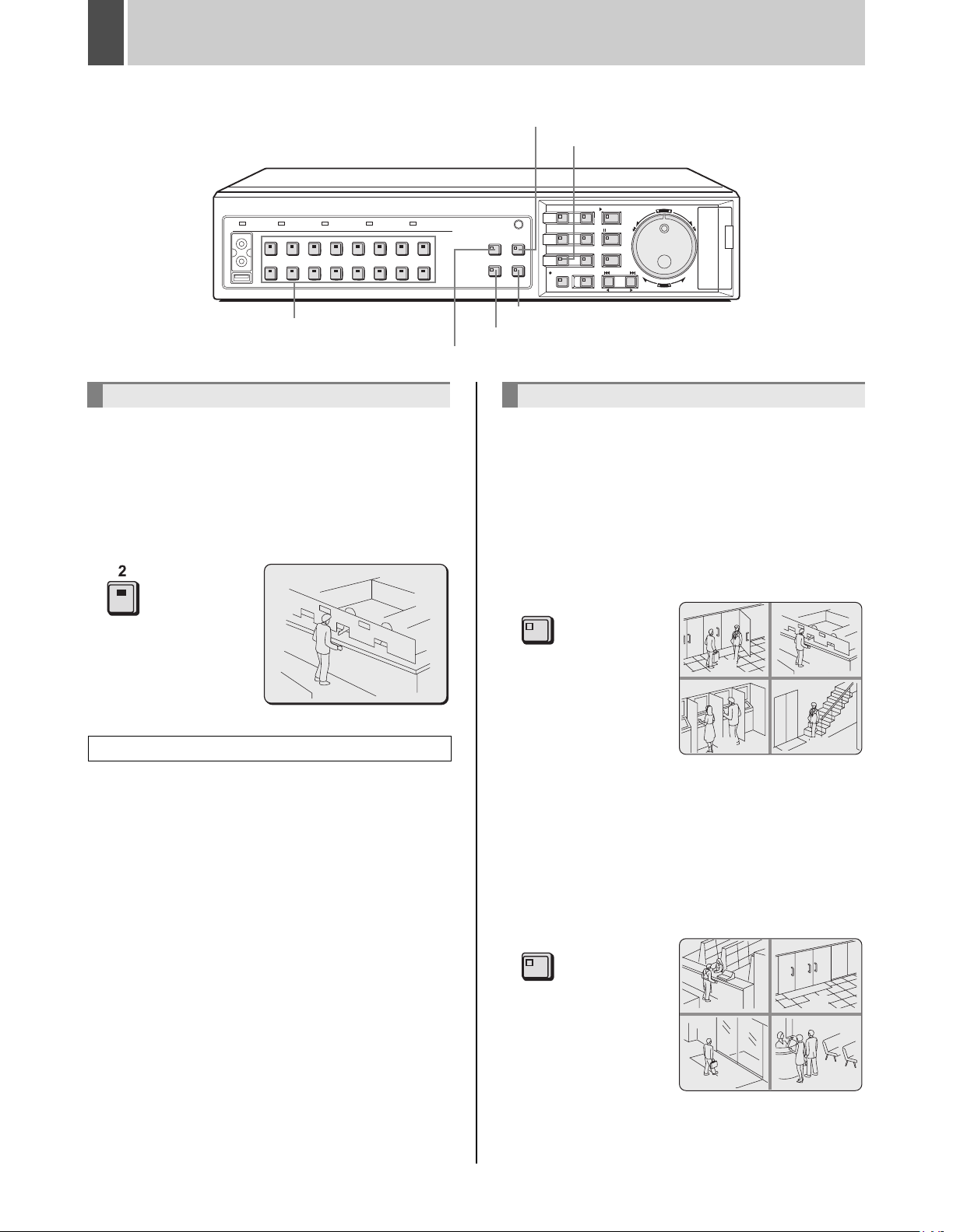
Viewing on a full screen
Example: Selecting Camera 2
1 Press the No. 2 [CAMERA SELECT]
button.
The No. 2 CAMERA SELECT indicator lights up and video
from Camera 2 is displayed on a full screen.
02
Viewing enlarged live images
Images can be enlarged while monitoring on a full screen.
Operations are the same as “Enlarging the playback
video”. See P.27 for more details.
[PLUS] button
[MON2] button
Viewing on quad screens
Images from multiple connected cameras can be
displayed simultaneously.
1 Press the [QUAD] button.
The QUAD indicator lights up and video from four separate
cameras is displayed simultaneously.
Video from Camera No. 1 through Camera No. 4 is
displayed.
QUAD
0201
0403
2 To view video from other cameras,
press the [QUAD] button again.
English 19
Each time this button is pressed, the four images on the
quad screen change, in order of cameras No. 1-4, 5-8, 912 and 13-16.
On the DSR-3709, the images change in order of cameras
No. 1-4, 5-8, 9-3, etc.
QUAD
0605
0807
3 To return to full screen display, press
the [CAMERA SELECT] button.
Page 21
VIEWING VIDEO FROM A CAMERA2
Viewing on multi screens (9 screens/
16 screens)
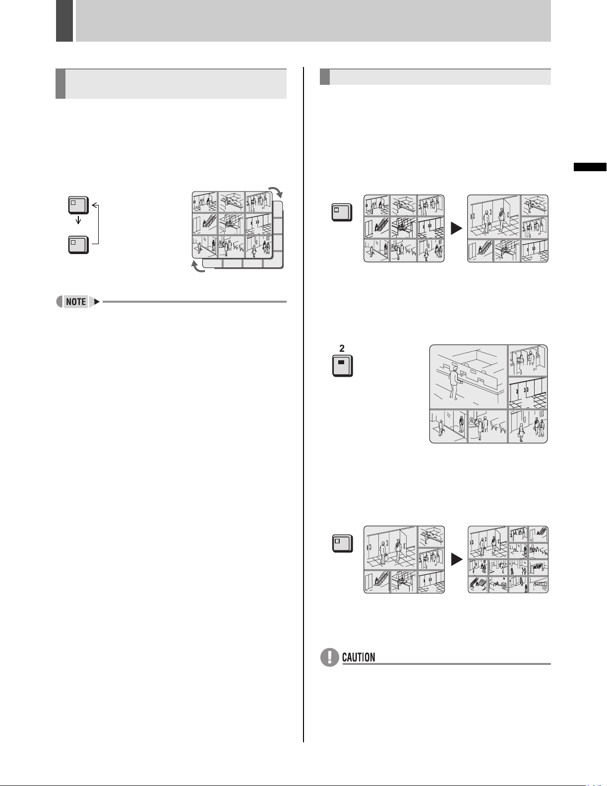
1 Press the [MULTI] button.
The MULTI indicator lights up and video from nine
separate cameras is displayed simultaneously. Press the
[MULTI] button again to display video from 16 cameras.
The DSR-3709 can only display video from nine cameras.
MULTI
0302
06
05
MULTI
01
04
07 08 09
13 14 15 16
z For both quad and multi 9/16 screen display, display
positions can be changed. (JP.100)
2 To return to full screen display, press
the [CAMERA SELECT] button.
Viewing on plus screen
Enlarge one camera video to quad screen size to view in
multi 6/13 screen display.
For DSR-3709, this operation is available only when in
multi 9 screen display.
1 Press the [PLUS] button.
PLUS indicator lights and one camera image is enlarged.
PLUS
01
01
04
04
07 08 09
07 08 09
0302
0302
06
06
05
05
01
04
01
07 08 09
07 08 09
0302
03
06
06
05
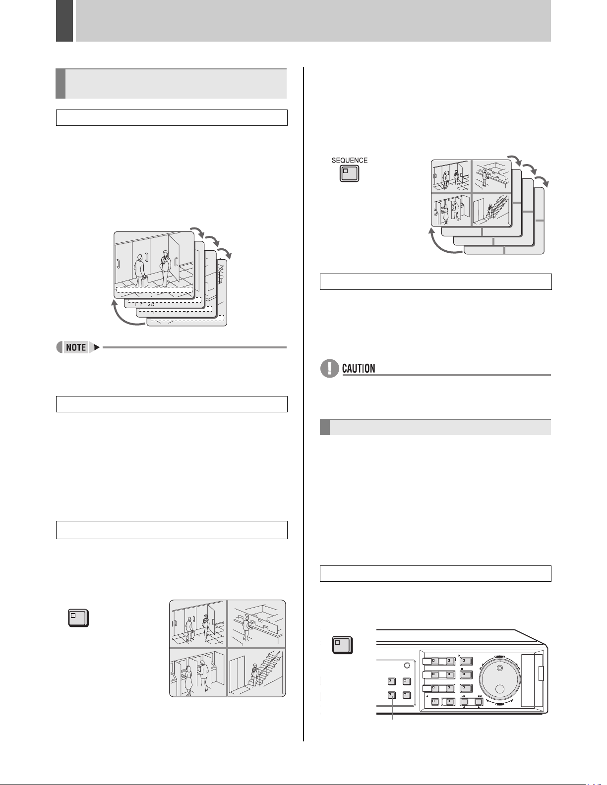
2 Press the corresponding [CAMERA
SELECT] button to change enlarged
camera image.
The video from the selected camera is enlarged.
01
0302
03
OPERATION
04
02
05
07 08 09
07 08 09
06
06
3 Press [MULTI] button to switch from
multi 6 screen display to multi 13 screen
display.
Operation can be performed solely with DSR-3716.
MULTI
01
04
01
07 08 09
07 08 09
0302
03
06
06
05
01
09 10 11 12
13 14 15
03 04
07 08
4 Press [PLUS] button to return to the
previous display.
z The time required for updating differs for each image.
12
16
20 English
Page 22
VIEWING VIDEO FROM A CAMERA2
Viewing with automatic screen
selection
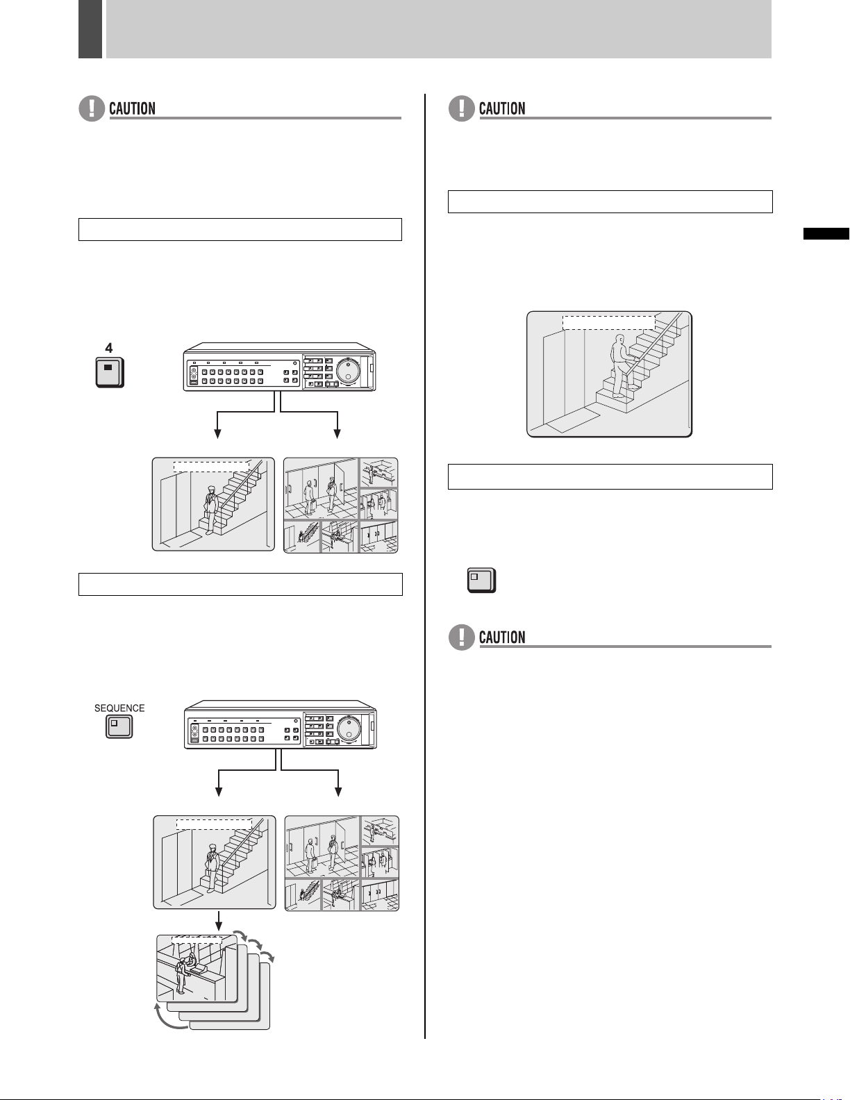
Setting automatic full screen selection
Use the following procedure when viewing a full screen to
have the displayed video change automatically based on
camera numbers.
1 Press the [SEQUENCE] button.
The SEQUENCE indicator starts to flash and the displayed
video changes automatically based on camera numbers.
01-01-04 00:00:00 REC REPEAT EN A ALARM 0000
01
04-01-01 00:00:00 REC REPEATENA ALARM 0000
02
01-01-01 00:00:00 REC REPEATENA ALARM 0000
15
02-01-01 00:00:00 REC REPEATENA ALARM 0000
16
2 Press the [SEQUENCE] button.
The content of the split screen will automatically toggle
between video from cameras No. 1 through No. 4 and
video from cameras No. 5 through No. 8, No. 9 through
No. 12 and No. 13 through No. 16
On the DSR-3709, the video changes automatically in
order of cameras No. 1-4, 5-8, 9-3, etc.
01
03
07
Returning to normal quad-screen display
3
Press the [SEQUENCE] button once again.
Automatic selection ends and normal quad-screen display
returns.
02
04
08
11
12
15
16
z It is possible to specify the cameras for which automatic
selection is to be carried out. (JP.102)
Canceling automatic selection
2 Either press the [SEQUENCE] button
once again or press the appropriate
[CAMERA SELECT], [QUAD], or [MULTI]
button.
Automatic selection ends and the display returns to the
normal screen.
Setting automatic quad-screen selection
1 Press the [QUAD] button.
The QUAD indicator lights up and the monitor display is
divided in four.
QUAD
0201
z Automatic selection cannot be used with playback
video.
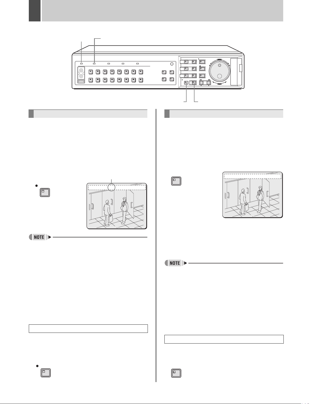
Viewing on the monitor 2
When a monitor 2 is connected to the monitor 2 output
terminal on the digital video recorder’s rear panel, this
monitor can be used to view video from a single camera or
to automatically scroll through video from all cameras,
even if the main monitor is currently displaying video in
split-screen format. In addition, it is also possible to display
video on the monitor 2 automatically from any camera for
which an alarm has occurred. By default, automatic full
screen selection is carried out.
Change the monitor 2 setting
1 Press the [MON2] button.
The MON2 indicator lights up.
MON2
0403
English 21
[MON2] button
CARDCARD
MENU
RESET
EJECT
Page 23
VIEWING VIDEO FROM A CAMERA2
z Monitor 2 operation is not possible when a menu screen
is being displayed.
z As the [EXIT/OSD] button is pressed, the operating
display moves to a different location or is hidden in the
same manner as the main monitor. (JP.16)
Selecting Camera No. 4 for full screen
2 Press the No. 4 [CAMERA SELECT]
button.
The video from Camera No. 4 is displayed in full screen
format on the monitor 2.
CARDCARD
MENU
RESET
EJECT
Monitor 2
01-01-04 00:00:00
Main Monitor
01
03
06
z If the monitor 2 is not synchronized with the connected
cameras, vertical picture instability may occur upon the
switching of camera video.
Displaying alarm video in full screen format
1 Set “MON.2 DISPLAY” from <ALARM
OPERATION SET> to “ON”. (JP.84)
When an alarm occurs, the corresponding video is
displayed in full screen format on the monitor 2.
01-01-04 00:00:00
02
Ending the monitor 2 setting procedure
1 Press the [MON2] button.
OPERATION
04
Setting automatic full screen selection
1 Press the [SEQUENCE] button.
The video displayed on the monitor 2 changes
automatically based on camera numbers.
Press the [SEQUENCE] button once again to cancel
automatic selection.
Monitor 2
01-01-04 00:00:00
04
01-01-04 00:00:00
Main Monitor
01
0907 08
The MON2 indicator turns off.
MON2
z Playback video cannot be viewed on the monitor 2.
CARDCARD
MENU
RESET
EJECT
03
06
0907 08
05
06
03
04
22 English
Page 24
3 RECORDING
POWER indicator
FULL indicator
[REC/STOP] button [TIMER] button
Normal recording
Use the following procedure to record the monitored video
in the normal recording area.
Recording will not be possible until a time has been set for
the digital video recorder. Make sure to set the time.
(JP.17)
1 Press the [REC/STOP] button.
The REC/STOP indicator lights up, “REC” appears onscreen (i.e., the recording symbol), and recording starts.
Recording symbol
REC/STOP
01-01-04 00:00:00 REC REPEAT EN A ALARM 0000
0
CARDCARD
MENU
RESET
EJECT
Timer recording
Use the following procedure to record the monitored video
for a preset length of time in the normal recording area.
Recording will not be possible until a time has been set for
J
the digital video recorder. Make sure to set the time. (
P.17)
1 Press the [TIMER] button.
The TIMER indicator lights up and the digital video
recorder enters timer recording standby mode.
TIMER
01-01-04 00:00:00 REC REPEAT EN A ALARM 0000
0
02
z When recording for the first time, the default settings
are used. For details regarding modification of the
picture quality or recording rate, see P.71.
z When the space remaining in the normal recording area
drops below a preset value, the FULL indicator on the
digital video recorder’s front panel starts to flash. If
recording is continued beyond this point, the normal
recording area will become full, recording will stop, and
the FULL indicator will stop flashing and remain lit. In
such a case, use the <RECORDING AREA SET>
screen to perform “AREA FULL RESET” for the normal
recording area, thus allowing recording to start again
from the beginning. (JP.67)
z Playback is possible even while recording. See P.26 for
more details.
Ending normal recording
2 Press and hold the [REC/STOP] button
for approximately 3 seconds.
“REC” disappears from the operation display and
recording ends.
REC/STOP
02
(1) See P.74 for more details on timer recording settings.
(2) At the time specified for the start of timer recording, the
REC/STOP indicator lights up, “REC” appears onscreen (i.e., the recording symbol), and recording starts.
(3) At the time specified for the end of timer recording, the
REC/STOP indicator turns off, and recording ends.
The [TIMER] button remains lit up.
z When the space remaining in the normal recording area
drops below a preset value, the FULL indicator on the
digital video recorder’s front panel starts to flash. If
recording is continued beyond this point, the normal
recording area will become full, recording will stop, and
the FULL indicator will stop flashing and remain lit. In
such a case, use the <RECORDING AREA SET> menu
to perform “AREA FULL RESET” for the normal
recording area, thus allowing recording to start again
from the beginning. (JP.67)
z Playback is possible even while recording. See P.26 for
more details.
Stopping timer recording before completion
2 Press the [TIMER] button.
The TIMER indicator turns off and recording ends.
TIMER
English 23
Page 25
RECORDING3
POWER indicator
ALARM FULL indicator
Alarm recording
Use the following procedure to automatically record alarm
video to the alarm recording area when an alarm signal is
detected.
Recording will not be possible until a time has been set for
the digital video recorder. Make sure to set the time.
(JP.17)
1 Set alarm recording.
Follow the instructions on
MODE SET” from <RECORD SET>.
P.77
to set “7. ALARM REC
<RECORD SET>
1.NORMAL REC EASY SET ->
2.RECORDING AREA SET ->
3.RECORDING CONDITIONS SET ->
4.NORMAL REC MODE SET ->
5.PROGRAM REC SET ->
6.TIMER SET ->
7.ALARM REC MODE SET ->
8.ALARM OPERATION SET ->
MOVE:JOG SELECT:SHUTTLE
2 Press the [EXIT/OSD] button.
[EXIT/OSD] button
CARDCARD
MENU
RESET
EJECT
01-01-04 00:00:00 REC REPEAT EN A ALARM 0000
Counts the number
of alarms.
Values between
0000 and 9999 can
be displayed.
02
z If an alarm occurs during normal recording or timer
recording, the recording operation will be cancelled.
z A maximum of 16,000 alarm recordings can be made
on one hard disk. If hard disk expansion is carried out,
this number can be increased to 32,000. Note,
however, since settings for each condition will affect the
maximum number of recordings that can be made, be
sure to check menu settings and display content.
3 End alarm recording.
When the alarm duration has expired (default setting: 20
seconds), both “REC” and “ALARM” finish flashing from
the operation display and recording stops.
OPERATION
The setting procedure is ended and the display returns to
the normal screen.
EXIT/OSD
When an alarm signal is detected
z When an alarm signal is detected, “ALARM” flashes in
the operation display and the alarm recording starts
(indicated by “REC”).
z Alarm video is recorded to the alarm recording area.
z Whenever an alarm occurs, the number of alarms as
indicated in the operation display is incremented.
z When the space remaining in the alarm recording area
drops below a preset value, the ALARM FULL indicator
on the digital video recorder’s front panel starts to flash.
If recording is continued beyond this point, the alarm
recording area will become full, recording will stop, and
the ALARM FULL indicator will stop flashing and remain
lit. In such a case, use the <RECORDING AREA SET>
menu to perform “AREA FULL RESET” for the alarm
recording area, thus allowing recording to start again
from the beginning. (JP.67)
z When normal recording area is set to “*0%,” alarm
recording can be executed as long as there is
remaining space on the hard disk. More than 16,000
alarm recordings can be recorded on each hard disk.
(JP.65)
24 English
Page 26
RECORDING3
Pre-alarm recording
Use the following procedure to record video from
immediately before occurrence of an alarm.
1 Set pre-alarm recording.
Follow the instructions on
SET” from <RECORD SET> to “PRE-ALARM
RECORDING”.
P.79
set “7. ALARM REC MODE
<ALARM REC MODE SET>
ALARM RECORDING : ENABLED
PICTURE QUALITY : ENHANCED
AUDIO RECORDING : ON
ALARM INTERLEAVE : ONLY
REC RATE: A 15FPS, DURATION: 20SEC
PRE-ALARM RECORDING : ON
REC RATE: A 15FPS, DURATION: 1MIN
=> (00371 ALARMS CAN BE RECORDED)
ALARM TRIGGER : ALARM
MOTION SENSOR ->
2 Press the [EXIT/OSD] button.
The setting procedure is ended and the display returns to
the normal screen.
“PRE” appears in the operation display area. Pre-alarm
recording starts (without the “REC” symbol being
displayed).
EXIT/OSD
01-01-04 00:00:00 EN A PRE 0000
If an alarm is detected
Pre-alarm recording is automatically ended and alarm
recording starts.
z “PRE” from the operation display area is replaced by
“ALARM”, and “ALARM” starts to flash.
01-01-04 00:00:00 REC REPEAT EN A ALARM 0000
02
z When recording for the first time, the default settings
are used. For details regarding modification of the
picture quality or recording rate, see P.71.
z When the space remaining in the alarm recording area
drops below a preset value, the ALARM FULL indicator
on the digital video recorder’s front panel starts to flash.
If recording is continued beyond this point, the alarm
recording area will become full, recording will stop, and
the ALARM FULL indicator will stop flashing and remain
lit. In such a case, use the <RECORDING AREA SET>
menu to perform “AREA FULL RESET” for the alarm
recording area, thus allowing recording to start again
from the beginning. (JP.67)
ALARM FULL indicator
02
English 25
Page 27
4 PLAYBACK
Use the following procedure to play video stored in the normal recording area (during normal or timer recording).
Normal
recording area
POWER indicator
[CAMERA SELECT] buttons
[ZOOM] button
[QUAD] button [MULTI] button [STILL] button
[PLAY/STOP] button
[SHUTTLE HOLD] button
Shuttle dial
CARDCARD
MENU
RESET
EJECT
Jog dial
OPERATION
Playing video on a full screen
1 Press the [PLAY/STOP] button.
The PLAY/STOP indicator lights up, and “ ” appears in
the operation display area. Video stored in the normal
recording area is played back. Use the appropriate
[CAMERA SELECT] button to select the camera whose
video is to be played.
PLAY/STOP
z Video playback begins at the start point of recording.
z If the start point of recording has been cleared or reset,
video playback will start from the earliest recording.
z When playback ends, the digital video recorder pauses
automatically.
The operation display area indicates that playback is
paused (using “ ”), and the STILL indicator lights.
z After being paused or stopped, playback resumes from
the stop point.
Operation
display area
01-01-04 00:00:00 EN A ALARM 0000
02
Fast-forward and fast-rewind
playback
1 Turn the shuttle dial clockwise or
counter-clockwise during video
playback.
When turned clockwise, the symbol “ ” appears in the
operation display area and fast-forward playback is
started.
When turned counter-clockwise, the symbol “ ” appears
in the operation display area and fast-rewind playback is
started.
Normal playback is resumed when you release the shuttle
dial.
z If the [SHUTTLE HOLD] button is pressed while the
shuttle dial is being turned and either “ ” or “ ” is
displayed, the speed of fast-rewind or fast-forward
playback will be maintained even after the dial is
released.
Ending playback
2 Press the [PLAY/STOP] button.
Playback ends.
PLAY/STOP
Playing video near the point of recording
The digital video recorder prioritizes recording operations,
and as a result, video playback may pause temporarily.
26 English
Page 28
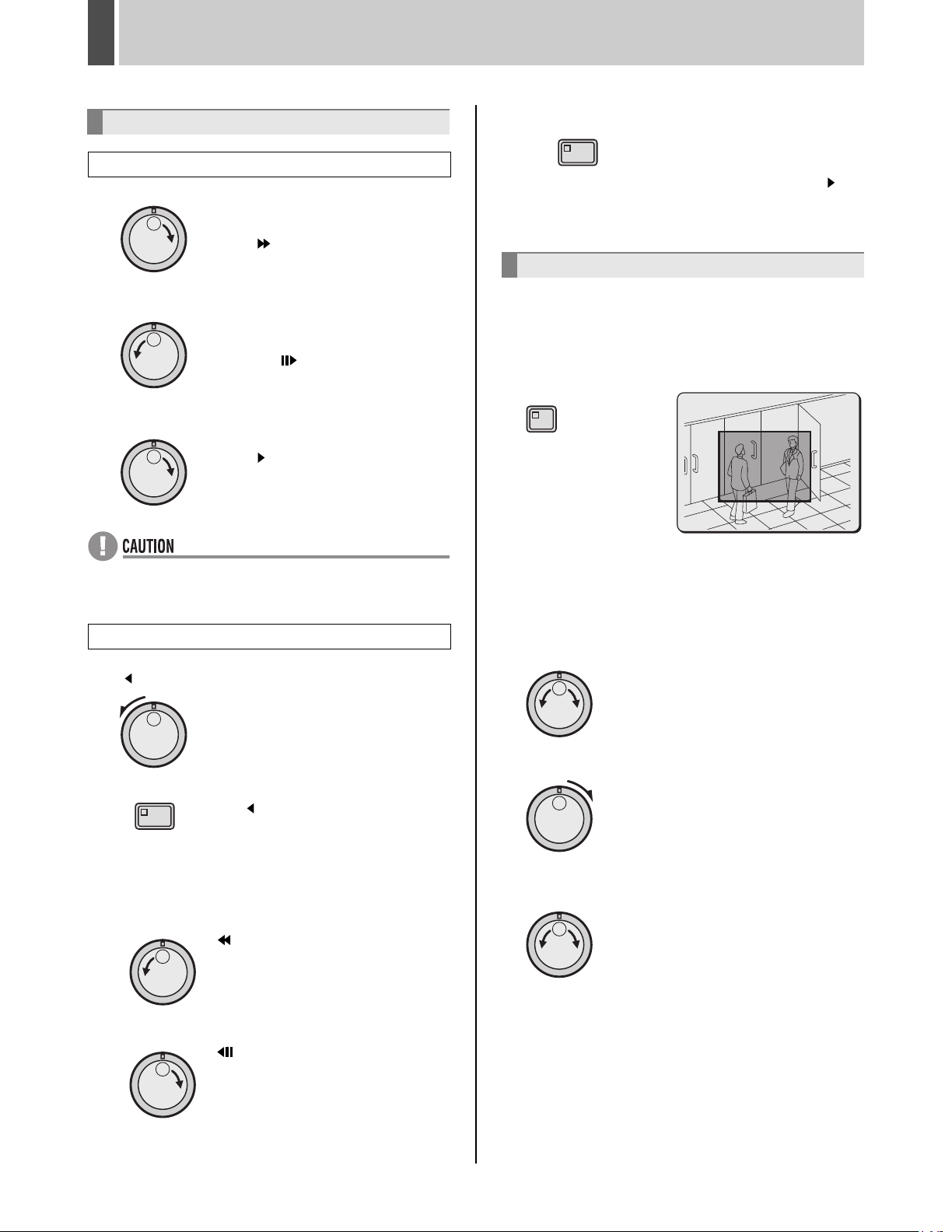
PLAYBACK4
Changing the playback speed
Starting fast-forward or slow playback
(1) Performing fast-forward.
When the jog dial is turned clockwise,
fast-forward playback is started and the
symbol “ ” appears in the operation
display area.
(2) Performing slow playback.
When the jog dial is turned counterclockwise, slow playback is started and
the symbol “ ” appears in the
operation display area.
(3) Returning to normal playback.
Turn the jog dial slightly clockwise to
display “ ”.
z Audio will not be played during fast-forward, fast-
rewind, slow, reverse-slow, and reverse playback.
Starting fast-rewind or reverse-slow playback
(1) Turn the shuttle dial counter-clockwise to display
“ ” in the operation display area.
Reverse playback starts at the same
speed as normal playback.
(2) Returning to normal playback.
SHUTTLE HOLD
Press the [SHUTTLE HOLD] button to
turn off SHUTTLE HOLD indicator.
Turn the shuttle dial either clockwise
or counter-clockwise to display “ ” in
the operation display area.
Normal video playback is restored.
Enlarging the playback video
1
Press the [ZOOM] button during
playback or monitoring of camera video.
ZOOM indicator lights and a zoom frame appears in the
center of the screen.
ZOOM
2 Move the zoom frame to the area to be
magnified.
z Turn the jog dial clockwise to move the zoom frame to
the right.
Turn the jog dial counter-clockwise to move the zoom
frame to the left.
SHUTTLE HOLD
z Turn the jog dial counter-clockwise.
z Turn the jog dial clockwise.
English 27
Press the [SHUTTLE HOLD] button
while “ ” is being displayed. The
SHUTTLE HOLD indicator lights up,
and even if the shuttle dial is now
released, reverse playback continues at
the current speed.
“ ” appears in the operation display
area and the speed of reverse
playback increases.
“ ” appears in the operation display
area and the speed of reverse
playback decreases.
z Turn the shuttle dial clockwise to switch to vertical
movement.
z Now, when the jog dial is turned clockwise, the zoom
frame moves down; when turned counter-clockwise, the
zoom frame moves up.
Page 29
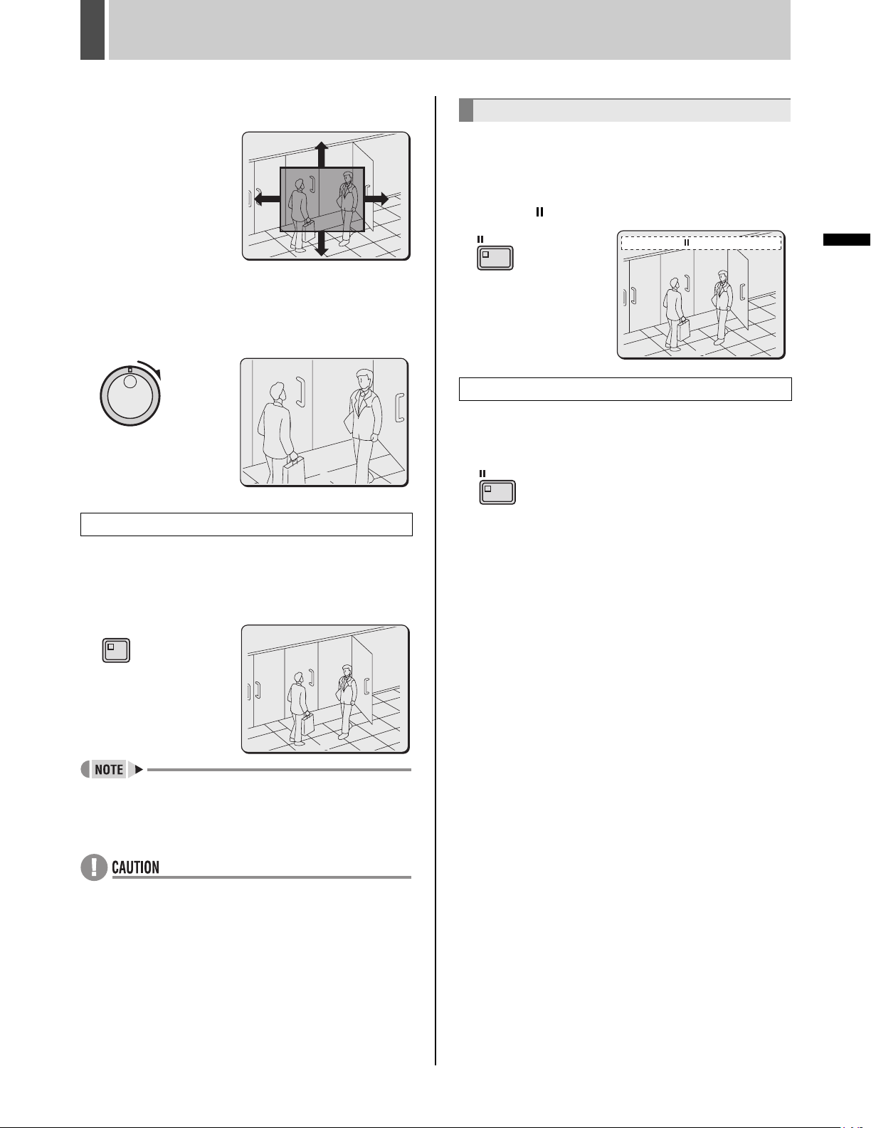
PLAYBACK4
z In this way, move the zoom frame to enclose the area of
video to be magnified.
3 Turn the shuttle dial clockwise.
The area enclosed by the zoom frame is magnified (by a
factor of 2).
02
Viewing still images
1 Press the [STILL] button during
playback.
The STILL indicator lights up and playback video is paused.
The symbol “ ” appears in the operation display area.
STILL
To resume playback
01-01-04 00:00:00 REPEAT EN A ALARM 0000
02
2 Press the [STILL] button once again.
Normal playback is restored.
STILL
OPERATION
Returning to normal magnification
4 Press the [ZOOM] button.
Magnification is cancelled and the display returns to the
normal screen. ZOOM indicator turns off.
ZOOM
02
z Magnification is not possible on monitor 2 or during
quad screen, multi-screen (9 screens/ 16 screens), or
plus screen display.
z Magnified video has a slightly coarser appearance
when compared with normal video.
28 English
Page 30
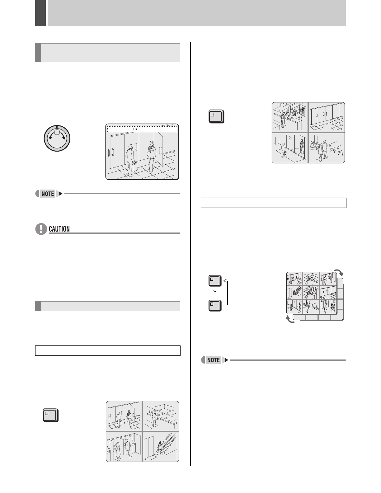
PLAYBACK4
Performing frame advance
(forward or reverse)
1 Turn the jog dial clockwise or counter-
clockwise while playback is paused.
Clockwise: The still image is moved forward by one frame
or field.
Counter-clockwise: The still image is moved back by one
frame or field.
01-01-04 00:00:00 REPEAT EN A ALARM 0000
02
z The jog dial can be turned to increase the speed of
frame advance.
2 Press the [QUAD] button.
Each time this button is pressed, the content of the split
screen will toggle between video from cameras No. 1
through No. 4 and video from cameras No. 5 through No.
8, No. 9 through No. 12 and No. 13 through No. 16.
On the DSR-3709, the images change in order of cameras
No. 1-4, 5-8, 9-3, etc.
QUAD
0605
0807
Returning to full screen display
Press the [CAMERA SELECT] button.
Playing video on multi 9 or multi 16 screens
1 Press the [MULTI] button.
z When the images from normal recording area and
alarm recording area are played back in succession, the
quality of the picture may drop momentarily as playback
switches from one recording area to another.
z If normal, fast-forward, or fast-rewind playback is
carried out either for playback during alarm recording or
for continuous playback from the normal recording area
and alarm recording area, the image may seem to have
paused in certain cases.
Playing video on multiple screens
If you are recording video from a number of different
cameras, the following procedures can be used to play the
recorded video in multi-screen format.
Playing video on quad screens
1 Press the [QUAD] button during
playback.
The QUAD indicator lights up and the monitor display is
divided in four.
QUAD
The MULTI indicator lights up and video from nine
separate cameras is displayed simultaneously. Press the
[MULTI] button again to display video from 16 cameras.
The DSR-3709 can only display video from nine cameras
at a time.
MULTI
0302
06
05
MULTI
01
04
07 08 09
13 14 15 16
Returning to full screen display
Press the [CAMERA SELECT] button.
z In the case of quad, multi 9 and 16 screen display you
can change the position in which playback video is
displayed. (JP.100)
0201
0403
English 29
Page 31

5 SEARCHING FOR RECORDED VIDEO
0011
Images stored in the normal recording area, alarm
recording area or archive area can be located by
searching and can then be played back. Use one of the
following five search methods to locate the required video.
Archive area
Alarm recording
area
Normal
recording area
[SEARCH] button
Shuttle dial
CARDCARD
Jog dial
MENU
RESET
EJECT
[ALARM] buttons
Searching from the <SEARCH> screen
(1)
(2)
(3)
(4)
<SEARCH>
ALARM SEARCH ->
ALARM THUMBNAIL SEARCH ->
TIME/DATE SEARCH ->
ARCHIVE AREA SEARCH ->
MOTION DETECTION SEARCH ->
(5)
MOVE:JOG SELECT:SHUTTLE
z During the playback of video, you can use the front-
panel buttons, the shuttle dial, and the jog dial to
perform operations such as pause and fast-forward.
z Search is unavailable during playback or menu display.
(1) ALARM SEARCH (JP.31)
Lets you search and playback alarm video from the
recording list.
<ALARM SEARCH>
NO DATE TIME CH TOTAL ALARMS
0016 01-05 09:53 1 00016
0015 01-05 09:53 1
0014 01-05 09:53 1
0013 01-05 09:53 1
0012 01-05 09:52 1
0011 01-05 09:51 1
0010 01-05 09:51 1
0009 01-05 03:10 1
MOVE:JOG SELECT:SHUTTLE
(2) ALARM THUMBNAIL SEARCH (JP.32)
Lets you search and playback alarm video using a
thumbnail list.
0016 0015 0014
0013 0012
0010 0009 0008
(3) TIME/DATE SEARCH (JP.32)
Lets you search and playback recorded video based
on date and time.
<TIME/DATE SEARCH>
RECORDING TOP : 01-16-04 14:46
RECORDING END : 01-19-04 13:32
CHANNEL : - SEARCH :
DATE TIME
01-16-04 14:46
PREVIEW ->
VIEW ->
CHANGE:JOG SET:SHUTTLE
(4) ARCHIVE AREA SEARCH (JP.34)
Lets you playback video that has been stored in the
archive area.
<ARCHIVE AREA SEARCH>
NO DATE START CH CAPACITY
0001 01-01 01:48 1 TOTAL - 816MB
0002 01-05 09:53 1 USED - 16MB
0003 01-01 02:41 1
0004 01-02 03:10 1
0005 01-02 04:25 1
0006 01-04 02:40 1
0007 01-04 01:25 1
0008 01-04 01:25 1
MOVE:JOG SELECT:SHUTTLE
0011
0011
OPERATION
(5) MOTION DETECTION SEARCH (JP.34)
Lets you search and playback video of moving objects
detected by motion sensors.
<MOTION DETECTION SEARCH>
SEARCH FROM : ALARM
START : 01-01-04 00:40
END : 01-05-04 10:17
CHANNEL : --
START PREVIEW ->
MOVE:JOG SELECT:SHUTTLE
- - - - - - - - - -
- - - - - - - - - -
- - - - - - - -
- - - - - - - -
- - - - - - - -
- - - - - - - - - -
- - - - - - - - - -
- - - - - - - - - -
LEVEL : OFF EXIT
30 English
Page 32

SEARCHING FOR RECORDED VIDEO5
Alarm search
Use the following procedure to search and playback all
video stored in the alarm recording area. If pre-alarm video
is being recorded, playback will start from immediately
before the alarm.
1 Press the [SEARCH] button while the
digital video recorder is recording or
stopped.
The SEARCH indicator lights up and the <SEARCH>
screen is displayed.
SEARCH
<SEARCH>
ALARM SEARCH ->
ALARM THUMBNAIL SEARCH ->
TIME/DATE SEARCH ->
ARCHIVE AREA SEARCH ->
MOTION DETECTION SEARCH ->
MOVE:JOG SELECT:SHUTTLE
2 Turn the jog dial to select “ALARM
SEARCH”, and then turn the shuttle dial
clockwise.
The <ALARM SEARCH> screen is displayed.
The eight most-recent alarm recordings are displayed.
(1) (2) (3) (4)
<ALARM SEARCH>
NO DATE TIME CH TOTAL ALARMS
0016 01-05 09:53 1 00016
0015 01-05 09:53 1
0014 01-05 09:53 1
0013 01-05 09:53 1
0012 01-05 09:52 1
0011 01-05 09:51 1
0010 01-05 09:51 1
0009 01-05 03:10 1
MOVE:JOG SELECT:SHUTTLE
(5)
3 Turn the jog dial to select the video for
playback.
A preview of the selected alarm video is displayed in the
preview screen. In this case, the video from the instant of
alarm occurrence is displayed.
z To display the next or previous recording
Turn the jog dial clockwise or counter-clockwise accordingly.
z To leave search mode
Press the [SEARCH] button. SEARCH indicator turns off.
4 Turn the shuttle dial clockwise.
The selected recording is played back in full screen mode.
01-01-04 00:00:00 EN A ALARM 0000
02
To view pre-alarm video
After beginning playback of an alarm recording identified by
an alarm search, use the shuttle dial to reverse playback.
To view alarm video before or after the current
playback
1 Press the appropriate [ALARM] button
during playback.
ALARM
01-01-04 00:00:00 EN A ALARM 0000
(1) NO:
Indicates the alarm number.
(2) DATE/TIME:
Indicates the date and time at which the alarm video
was recorded.
(3) CH:
Indicates the alarm video’s channel (or camera
number).
(4) TOTAL ALARMS:
Indicates the total number of alarm video recordings.
(5) Preview:
Displays the selected alarm video.
English 31
02
z Each time the “ ” button is pressed, playback will
skip to the preceding alarm video recording.
z Each time the “ ” button is pressed, playback will
skip to the subsequent alarm video recording.
z
When playback is performed after an alarm search, the frame
at the start and end of each alarm recording will be paused.
Press the appropriate [ALARM] button to play the
previous or next alarm recording.
z
You can use the front-panel buttons, the shuttle dial, and the
jog dial to perform operations such as pause and fast-forward.
Page 33

SEARCHING FOR RECORDED VIDEO5
0011
Alarm thumbnail search
Use the following procedure to display all of the alarm
recordings stored in the alarm recording area as
thumbnails list.
1 Press the [SEARCH] button while the
digital video recorder is recording or
stopped.
The SEARCH indicator lights up and the <SEARCH>
screen is displayed.
SEARCH
2 Turn the jog dial and select “ALARM
THUMBNAIL SEARCH”.
<SEARCH>
ALARM SEARCH ->
ALARM THUMBNAIL SEARCH ->
TIME/DATE SEARCH ->
ARCHIVE AREA SEARCH ->
MOTION DETECTION SEARCH ->
MOVE:JOG SELECT:SHUTTLE
5 Turn the shuttle dial clockwise.
The selected recording is played back in full screen mode.
To view pre-alarm video
After beginning playback of an alarm recording identified
by an alarm search, use the shuttle dial to reverse
playback.
z In the same way as for alarm searching, playback is
only possible within each individual alarm recording.
Press the appropriate [ALARM] button to play the
previous or next recording.
z You can use the front-panel buttons, the shuttle dial,
and the jog dial to perform operations such as pause
and fast-forward.
Time/date search
Use the following procedure to play a recording from the
normal recording area (i.e., a normal recording or timer
recording) or alarm recording area by specifying its date
and time.
OPERATION
3 Turn the shuttle dial clockwise.
The nine most-recent alarm recordings are displayed.
An alarm number is indicated together with each alarm
recording, and the number of the currently selected
recording will flash.
0016 0015 0014
0013 0012
0010 0009 0008
0011
0011
4 Turn the jog dial to select the alarm
recording for playback.
The alarm number for the selected recording will start to
flash.
z To display the next or previous recording
Turn the jog dial clockwise or counter-clockwise
accordingly.
1 Press the [SEARCH] button while the
digital video recorder is recording or
stopped.
The SEARCH indicator lights up and the <SEARCH>
screen is displayed.
SEARCH
2 Turn the jog dial to select “TIME/DATE
SEARCH”.
<SEARCH>
ALARM SEARCH ->
ALARM THUMBNAIL SEARCH ->
TIME/DATE SEARCH ->
ARCHIVE AREA SEARCH ->
MOTION DETECTION SEARCH ->
MOVE:JOG SELECT:SHUTTLE
z To leave search mode
Press the [SEARCH] button. SEARCH indicator turns off.
32 English
Page 34

SEARCHING FOR RECORDED VIDEO5
3 Turn the shuttle dial clockwise.
The <TIME/DATE SEARCH> screen is displayed.
(1)
(3)
(5)
(1) RECORDING TOP:
Indicates the date/time of the earliest video recording.
(2) RECORDING END:
Indicates the date/time of the most-recent video
recording.
(3) CHANNEL:
Used to enter the channel (or camera number) for
playback.
(4) SEARCH:
Used to enter the date/time of the recording to be
played.
(5) PREVIEW:
Select this option and turn the shuttle dial clockwise to
display the preview screen.
(6) VIEW:
Select this option and turn the shuttle dial clockwise to
play the recording.
<TIME/DATE SEARCH>
RECORDING TOP : 10-01-04 14:46
(2)
RECORDING END : 10-30-04 13:32
CHANNEL : --
(4)
SEARCH :
DATE TIME
10-26-04 20:30
PREVIEW ->
(6)
VIEW ->
CHANGE:JOG SET:SHUTTLE
4 Turn the shuttle dial clockwise.
After searching, the recording for the date and time
settings is displayed in the preview screen.
<TIME/DATE SEARCH>
RECORDING TOP : 10-01-04 14:46
RECORDING END : 10-30-04 13:32
CHANNEL : 05
SEARCH :
DATE TIME
10-26-04 20:30
PREVIEW -> SEARCHING
VIEW ->
CHANGE:JOG SET:SHUTTLE
z If no recording exists for the specified time
The closest recording to the specified time is displayed.
z To leave search mode
Press the [SEARCH] button. The display returns to the
normal screen.
5 Turn the jog dial clockwise to select
“VIEW”, and then turn the shuttle dial
clockwise.
The selected recording is played back on the full screen.
Example: To search for a recording from camera 5
from 8:30 pm on October 26, 2004
<TIME/DATE SEARCH>
RECORDING TOP : 10-01-04 14:46
Date and time
for searching
10-26-04 20 : 30
(2)
(3)
(4)
(5)
RECORDING END : 10-30-04 13:32
(1)
CHANNEL : 05
SEARCH :
DATE TIME
10-26-04 20:30
PREVIEW ->
VIEW ->
(6)
CHANGE:JOG SET:SHUTTLE
Turn the jog dial to select “CHANNEL”.
(1) Turn the shuttle dial clockwise, turn the jog dial to
select “05”, and then turn the shuttle dial clockwise
once again.
(2) Turn the shuttle dial clockwise, and then turn the jog
dial to change to “10” (month).
(3) Turn the shuttle dial clockwise, and then turn the jog
dial to change to “26” (day).
(4) Turn the shuttle dial clockwise, and then turn the jog
dial to select “04” (year).
(5) Turn the shuttle dial clockwise, and then turn the jog
dial to select “20” (hour).
(6) Turn the shuttle dial clockwise, turn the jog dial to
change to “30” (minutes), and then turn the shuttle dial
clockwise once again.
The cursor moves to “PREVIEW”.
z The retrieved video can be displayed on the full screen
without displaying the preview screen by entering the
date and time, and by then selecting “VIEW”.
z You can use the front-panel buttons, the shuttle dial,
and the jog dial to perform operations such as pause
and fast-forward.
z If “CHANNEL” is set to “--” and playback is started, this
will take place on the multi screen.
English 33
Page 35

SEARCHING FOR RECORDED VIDEO5
Archive area search
Use the following procedure to playback video that has
been stored in the archive area.
1 Press the [SEARCH] button while the
digital video recorder is recording or
stopped.
The SEARCH indicator lightsup and the <SEARCH>
screen is displayed.
SEARCH
2 Turn the jog dial to select “ARCHIVE
AREA SEARCH”.
<SEARCH>
ALARM SEARCH ->
ALARM THUMBNAIL SEARCH ->
TIME/DATE SEARCH ->
ARCHIVE AREA SEARCH ->
MOTION DETECTION SEARCH ->
MOVE:JOG SELECT:SHUTTLE
4 Turn the jog dial to select the video for
playback.
The selected image is displayed on the preview screen.
z To display the next or previous recording
Turn the jog dial clockwise or counter-clockwise
accordingly.
z Up to eight recordings can be displayed in the
<ARCHIVE AREA SEARCH> screen.
z To leave search mode
Press the [SEARCH] button. SEARCH indicator turns
off.
5 Turn the shuttle dial clockwise.
The selected recording is played back on the full screen.
OPERATION
3 Turn the shuttle dial clockwise.
The <ARCHIVE AREA SEARCH> screen is displayed.
This screen lists the eight most-recent recordings in the
order in which archiving was performed.
(2) (4)
(1) (3)
<ARCHIVE AREA SEARCH>
NO DATE START CH CAPACITY
0001 01-01 01:48 1 TOTAL - 816MB
0002 01-05 09:53 1 USED - 16MB
0003 01-01 02:41 1
0004 01-02 03:10 1
0005 01-02 04:25 1
0006 01-04 02:40 1
0007 01-04 01:25 1
0008 01-04 01:25 1
MOVE:JOG SELECT:SHUTTLE
(1) NO: Indicates the archive number.
(2) DATE: Indicates the date of recording.
(3) START: Indicates the start time for the recording.
(4) CH: Indicates the channel (or camera number) for the
recording.
(5) TOTAL: Indicates the total capacity of the archive
area.
(6) USED: Indicates the amount of the archive area that
has been used.
(5)
(6)
Motion detection search
By setting the motion sensor for recordings from the
normal recording area (i.e., normal recordings and timer
recordings) or alarm recording area, variations from these
recordings as a result of the presence of an intruder or the
like can be detected, and the corresponding video can be
played back.
z When a camera number (or channel) is specified,
searching will only be carried out for that camera.
1 Press the [SEARCH] button while the
digital video recorder is recording or
stopped.
SEARCH indicator lights up and the <SEARCH> screen is
displayed.
SEARCH
34 English
Page 36

SEARCHING FOR RECORDED VIDEO5
2 Turn the jog dial to select “MOTION
DETECTION SEARCH”, and then turn
the shuttle dial clockwise.
The <MOTION DETECTION SEARCH> screen is
displayed.
<MOTION DETECTION SEARCH>
SEARCH FROM : ALARM
START : 01-01-04 00:40
END : 01-05-04 10:17
CHANNEL : --
START PREVIEW ->
MOVE:JOG SELECT:SHUTTLE
3 Turn the jog dial to select “SEARCH
FROM”, and then turn the shuttle dial
clockwise.
The ALARM indicator starts to flash.
<MOTION DETECTION SEARCH>
SEARCH FROM : ALARM
START : 01-01-04 00:40
END : 01-05-04 10:17
CHANNEL : --
START PREVIEW ->
MOVE:JOG SELECT:SHUTTLE
4 Turn the jog dial to select a search area,
and then turn the shuttle dial clockwise.
Example: ALARM
The cursor moves to “CHANNEL”.
<MOTION DETECTION SEARCH>
SEARCH FROM : ALARM
START : 01-01-04 00:40
END : 01-05-04 10:17
CHANNEL : --
START PREVIEW ->
MOVE:JOG SELECT:SHUTTLE
[Settings] (indicates default setting)
Setting Description
ALARM
NORMAL
ALARM &
NORMAL
Searching will only be performed for
recordings in the alarm recording area.
Searching will only be performed for
recordings in the normal recording area.
Searching will be performed for recordings
in the alarm recording area and normal
recording area.
5 Turn the shuttle dial clockwise, and
then turn the jog dial to select a camera
number.
Example: 4
6 Turn the shuttle dial clockwise.
The cursor moves to “START PREVIEW”.
<MOTION DETECTION SEARCH>
SEARCH FROM : ALARM
START : 01-01-04 00:40
END : 01-05-04 10:17
CHANNEL : 4
START PREVIEW ->
MOVE:JOG SELECT:SHUTTLE
7 Turn the shuttle dial clockwise.
The screen changes and the preview screen for Camera
No. 4 appears.
<MOTION DETECTION SEARCH>
SEARCH FROM : ALARM / CHANNEL : 4
(1)
START :
01-05-04 10:00
(2)
END :
01-05-04 10:17
(3)
(4)
(1) START:
Indicates the date and time of recording of the first
image in the selected recording area(s).
(2) END:
Indicates the date and time of recording of the final
image in the selected recording area(s).
(3) MOTION SENSOR:
Indicates the motion sensor setting.
(4) PREVIEW:
Displays the selected start image.
(5) VIEW:
Plays the selected recording on the full screen.
MOTION SENSOR ->
PREVIEW ->
(5)
VIEW ->
MOVE:JOG SELECT:SHUTTLE
English 35
Page 37

SEARCHING FOR RECORDED VIDEO5
Set the motion sensor to use for searching
1 Turn the shuttle dial clockwise while
video is being displayed on the preview
screen.
(1) Turn the jog dial to set the start date and time for
motion sensing (i.e., 10 AM on the same day), and
then turn the shuttle dial clockwise.
The recording for the selected time is displayed in the
preview screen. The cursor moves to the “END” date
and time.
<MOTION DETECTION SEARCH>
SEARCH FROM : ALARM / CHANNEL : 4
Set the start
date and time.
(2) Turn the shuttle dial clockwise.
(3) Turn the jog dial to set the end date and time for
motion sensing (i.e., 8 PM on the same day), and then
turn the shuttle dial clockwise. The cursor moves to
“MOTION SENSOR”.
START :
01-05-04 10:00
END :
01-05-04 10:17
MOTION SENSOR ->
PREVIEW ->
VIEW ->
MOVE:JOG SELECT:SHUTTLE
(2) Turn the shuttle dial clockwise to set a motion sensor.
: ON, : OFF
(3) Use the jog dial in the same way to set sensors at
other locations.
- - - - - - - - - -
- - - - - - - - - -
Typical
setting
z
All sensors on the same line as the cursor can be turned
- - - - - - - -
- - - - - - - -
- - - - - - - -
- - - - - - - - - -
- - - - - - - - - -
- - - - - - - - - -
LEVEL : OFF EXIT
on simultaneously by pressing the [MENU RESET] button.
3 Turn the jog dial to move the cursor to
“LEVEL”, and then turn the shuttle dial
clockwise.
“OFF” flashes.
OPERATION
<MOTION DETECTION SEARCH>
SEARCH FROM : ALARM / CHANNEL : 4
START :
01-05-04 10:00
END :
Set the end date
and time.
01-05-04 20:00
MOTION SENSOR ->
PREVIEW ->
VIEW ->
MOVE:JOG SELECT:SHUTTLE
2 Turn the shuttle dial clockwise.
The motion sensor setting screen is displayed.
Use the following procedure to set motion sensors at
locations where movement is to be detected and viewed.
(1) Turn the jog dial clockwise or counter-clockwise to
move the cursor to the position where a sensor is to
be set.
4 Turn the jog dial to select “OFF” or a
sensitivity level between “1” and “10”,
and then turn the shuttle dial clockwise.
After setting the sensitivity level, the cursor moves to “EXIT”.
[Settings] ( indicates default setting)
Setting Description
OFF Motion sensing is not carried out.
1 to 10
Motion sensing is carried out. Lower values correspond to higher sensitivities.
5 Turn the shuttle dial clockwise.
The display returns to the <MOTION DETECTION
SEARCH> screen.
36 English
Page 38

SEARCHING FOR RECORDED VIDEO5
6 Turn the jog dial to select “PREVIEW”.
<MOTION DETECTION SEARCH>
SEARCH FROM : ALARM / CHANNEL : 4
START :
01-05-04 10:00
END :
01-05-04 20:00
MOTION SENSOR ->
PREVIEW ->
VIEW ->
MOVE:JOG SELECT:SHUTTLE
7 Turn the shuttle dial clockwise.
Each time the shuttle dial is turned clockwise, a different
motion sensor screen will be displayed on the preview
screen.
If “NOT FOUND” is displayed
Carry out motion sensor setting again.
Viewing video detected by the motion sensor
on a full screen
8 Turn the jog dial to select “VIEW”, and
then turn the shuttle dial clockwise.
Normal playback will be started for the specified recording.
z By specifying a camera number (or channel) and
performing MOTION DETECTION SEARCH, playback
can be carried out for only the specified camera
number.
In such a case, the title information, date information,
and/or time information may partially disappear.
z To playback a recording from a different camera, stop
the current playback and then repeat the setting
process from the beginning.
English 37
Page 39

6 SAVING (COPYING) RECORDED VIDEO
Use the procedures described below to copy important video stored in the normal recording area or the alarm recording area
to the digital video recorder’s archive area, a CompactFlash card, a Microdrive or CD-R/RW.
Copying video to the hard disk’s archive area (JP.39)
Copy
Alarm recording
area
Copy
Archive area
Normal recording area
Copying video to a CompactFlash card or Microdrive (JP.41)
Automatic copy
Alarm recording
area
Normal recording area
Automatic copy
Archive area
CF card
Microdrive
CARDCARD
MENU
RESET
EJECT
OPERATION
Copying video to a CD-R/RW (JP.45)
Automatic copy
Alarm recording
area
Normal recording area
z Copied data is stored as a continuous recording.
z When video is being downloaded from the normal
recording area or alarm recording area to a
CompactFlash card, a Microdrive or CD-R/RW, it is
temporarily stored in the archive area before being
copied from there to each media. Consequently, the
amount of free space in the archive area is the
maximum amount that can be copied. Note, however,
that this video will not be retained in the archive area.
Automatic copy
Archive area
USB
CD-R/RW
z If archive area becomes full, copy important video to a
CompactFlash card, a Microdrive or CD-R/RW. (JP.41)
Following this, delete data from the archive area using
“AREA FULL RESET” from the “ARCHIVE AREA” in
“2.RECORDING AREA SET” on the <RECORD SET>
sub-menu. (JP.67)
38 English
Page 40

SAVING (COPYING) RECORDED VIDEO6
Copying video to the hard disk’s
archive area
[STILL] button
Shuttle dial
CARDCARD
Jog dial
MENU
RESET
EJECT
[COPY] button
1 Play video from the normal recording
area or the alarm recording area.
2 Press the [STILL] button when the frame
to be copied is displayed.
STILL
4 Turn the jog dial to select “COPY TO”,
and then turn the shuttle dial clockwise.
“ARCHIVE AREA” starts to flash.
[Settings] ( indicates default setting)
Setting Description
ARCHIVE AREA
COMPACT FLASH
CF->PRINT
CD-R/RW
Video will be copied to the archive area.
(JP.39)
Video will be copied to a CompactFlash
card. (JP.41)
Copy to a CompactFlash card and print
directly from a printer. (JP.43)
Copy to a CD-R/RW. This is only
displayed when a recordable CD-R/RW
drive is connected to the digital video
recorder. (JP.45)
COPY TO : ARCHIVE AREA
HOW MANY: 1 PICTURES
START ->
FORMAT : COMPACT FLASH
FORMAT START ->
CHANGE:JOG SET:SHUTTLE
z Images from all cameras cannot be copied
simultaneously. Use the appropriate [CAMERA
SELECT] button to select the camera whose video is to
be copied.
Example: Copying a specified 10-second
portion of video
3 Press the [COPY] button.
The COPY indicator lights up and the <COPY> screen is
displayed.
COPY
COPY TO : ARCHIVE AREA
HOW MANY: 1 PICTURES
START ->
FORMAT : COMPACT FLASH
FORMAT START ->
CHANGE:JOG SET:SHUTTLE
5 Turn the jog dial to select “ARCHIVE
AREA”, and then turn the shuttle dial
clockwise.
The cursor moves to “HOW MANY”.
6 Turn the shuttle dial clockwise, and
then turn the jog dial to set “HOW
MANY” to “10”.
Any value between 1 and 60 can be set.
COPY TO : ARCHIVE AREA
HOW MANY: 10 PICTURES
START ->
FORMAT : COMPACT FLASH
FORMAT START ->
CHANGE:JOG SET:SHUTTLE
English 39
Page 41

SAVING (COPYING) RECORDED VIDEO6
7 Turn the shuttle dial clockwise.
“PICTURES” flashes.
COPY TO : ARCHIVE AREA
HOW MANY: 10 PICTURES
START ->
FORMAT : COMPACT FLASH
FORMAT START ->
CHANGE:JOG SET:SHUTTLE
8 Turn the jog dial to select “SECONDS”.
COPY TO : ARCHIVE AREA
HOW MANY: 10 SECONDS
START ->
FORMAT : COMPACT FLASH
FORMAT START ->
CHANGE:JOG SET:SHUTTLE
[Settings] ( indicates default setting)
Setting Description
PICTURES
SECONDS
MINUTES
The specified number of images after the
specified location will be copied.
The specified duration in seconds after the
specified location will be copied.
The specified duration in minutes after the
specified location will be copied.
9 Turn the shuttle dial clockwise.
10 Turn the shuttle dial clockwise.
(1) Copying to the archive area commences.
The message “COPY TO ARCHIVE AREA !” is
displayed on-screen during the copy procedure.
COPY TO ARCHIVE AREA ! < 55% >
(2) When this procedure has been completed, “COPY
FINISHED !” is displayed.
COPY FINISHED ! < 100% >
To cancel a copy operation
Press the [COPY] button to cancel the current copy.
OPERATION
The cursor moves to “START”.
COPY TO : ARCHIVE AREA
HOW MANY: 10 SECONDS
START ->
FORMAT : COMPACT FLASH
FORMAT START ->
CHANGE:JOG SET:SHUTTLE
40 English
Page 42

SAVING (COPYING) RECORDED VIDEO6
Copying video to a CompactFlash
card or Microdrive
Use the following procedure to copy video either to a
Microdrive and to a CompactFlash card (Supported up to 2
GB).
Shuttle dial
CARDCARD
Jog dial
MENU
RESET
EJECT
[COPY] button
1 Insert a CompactFlash card.
Insertion method Removal method
(1)
(2)
Rear
surface
(3)
(2)
3 Turn the jog dial to select “COPY TO”,
and then turn the shuttle dial clockwise.
“ARCHIVE AREA” flashes.
COPY TO : ARCHIVE AREA
HOW MANY: 1 PICTURES
START ->
FORMAT : COMPACT FLASH
FORMAT START ->
CHANGE:JOG SET:SHUTTLE
4 Turn the jog dial to select “COMPACT
FLASH”, and then turn the shuttle dial
clockwise.
The cursor moves to “HOW MANY”.
COPY TO : COMPACT FLASH
HOW MANY: 1 PICTURES
START ->
FORMAT : COMPACT FLASH
FORMAT START ->
CHANGE:JOG SET:SHUTTLE
(3)
(1) Open the cover.
(2) Ensuring that it is correctly
oriented, insert the
CompactFlash card into the
CompactFlash card slot.
(3) Fold down the lever.
(1)
(1) Raise the lever.
(2) Push in the lever.
(3) Remove the
CompactFlash card.
Example: Copying a specified 10-second
portion of video
2 Pause playback on the image to be
copied, and then press the [COPY]
button.
The <COPY> screen is displayed.
COPY
COPY TO : ARCHIVE AREA
HOW MANY: 1 PICTURES
START ->
FORMAT : COMPACT FLASH
FORMAT START ->
CHANGE:JOG SET:SHUTTLE
5 Turn the shuttle dial clockwise, and
then turn the jog dial to set “HOW
MANY”.
COPY TO : COMPACT FLASH
HOW MANY: 10 PICTURES
START ->
6 Turn the shuttle dial clockwise.
“PICTURES” flashes.
COPY TO : COMPACT FLASH
HOW MANY: 10 PICTURES
START ->
7 Turn the jog dial to select “SECONDS”.
COPY TO : COMPACT FLASH
HOW MANY: 10 SECONDS
START ->
English 41
Page 43

SAVING (COPYING) RECORDED VIDEO6
[Settings] ( indicates default setting)
Setting Description
PICTURES
SECONDS
MINUTES
The specified number of images after the specified location will be copied.
The specified duration in seconds after the specified location will be copied.
The specified duration in minutes after the specified location will be copied.
z Up to 40,000 images can be copied in a single
operation. When specifying the number of images using
“MINUTES”, copying will end at the point at which
40,000 images are copied.
z Alarm recordings can only be copied one event at a
time.
8 Turn the shuttle dial clockwise.
The cursor moves to “START”.
COPY TO : COMPACT FLASH
HOW MANY: 10 SECONDS
START ->
z If the CompactFlash card becomes full during the
copying process, the message “COMPACT FLASH
FULL!” will be displayed and copying will end. Press
any button to return to the normal screen. The copy
procedure should now be repeated using a new
CompactFlash card.
z JPEG images
JPEG files contain field images, and for this reason,
they will be 50% compressed in the vertical direction
when viewed using commercially-available image
processing software. These files should, therefore, be
opened using the INDEX.HTM file.
z Images copied to a CompactFlash card
Since images copied to a CompactFlash card contain
embedded coding for the detection of manipulation,
these codes can be detected using a suitable software
application. For more information, contact the dealer
from whom you purchased this digital video recorder.
z Use a FAT16 CompactFlash card. The digital video
recorder will not recognize FAT32 CompactFlash cards.
Format cards with the digital video recorder before use.
OPERATION
FORMAT : COMPACT FLASH
FORMAT START ->
9 Turn the shuttle dial clockwise.
(1) Copying to the CompactFlash card starts. The
message “COPY TO COMPACT FLASH !” is
displayed on-screen at this time.
COPY TO COMPACT FLASH ! < 55% >
(2) When this has been completed, “COPY FINISHED !”
is displayed.
COPY FINISHED ! < 100% >
z When images are copied directly from the normal
recording area or the alarm recording area to a
CompactFlash card, these images will be temporarily
copied to the archive area. Consequently, the amount
of free space in the archive area is the maximum
amount that can be copied. Note, however, that this
data will be automatically deleted when copying has
been completed.
z When copying images to a CompactFlash card,
approximately 15 seconds will be required for 1 MB.
To cancel a copy operation
Press the [COPY] button to cancel the current copy.
42 English
Page 44

SAVING (COPYING) RECORDED VIDEO6
Viewing images copied to a CompactFlash
card on a PC
When images are copied to a CompactFlash card,
following folders are created and images are saved within
them.
CompactFlash card
SANYO
(1) (2) (3)
(1) A folder with the name “SANYO” is created inside the
root directory.
(2) Within "SANYO," a folder with the date on which
images were copied to is created.
(3) Under the date folder, folders with titles starting from
“IMG00001” are created. Up to 200 images can be
saved on each folder.
(4) To view images on your PC, open the file
“INDEX.HTM” found in each date folder using a
browser (i.e., Internet Explorer 5.0 or later). You will
then be able to view the JPEG images individually or
in slide show format, etc.
01010401
IMG00001
IMG00002
(3)
IMG00003
(3)
INDEX.HTM
(4)
00000001.JPG
00000002.JPG
00000003.JPG
Printing images from CompactFlash
cards (quick print)
Shuttle dial
CARDCARD
Jog dial
MENU
RESET
EJECT
[COPY] button
1 Insert a CompactFlash card.
See P.41 for inserting a CompactFlash card.
z Use a FAT16 CompactFlash card. The digital video
recorder will not recognize FAT32 CompactFlash cards.
Format cards with the digital video recorder before use.
2 Pause playback on the image to be
copied, and then press the [COPY]
button.
z Playing video with audio that has been copied to a
CompactFlash card
Video with audio can be played using DVR Viewer. For
more details, refer to the “Manual for Remote Operation
by Network Connection”.
The <COPY> screen is displayed.
COPY
COPY TO : ARCHIVE AREA
HOW MANY: 1 PICTURES
START ->
FORMAT : COMPACT FLASH
FORMAT START ->
CHANGE:JOG SET:SHUTTLE
3 Turn the jog dial to select “COPY TO”,
and then turn the shuttle dial clockwise.
“ARCHIVE AREA” flashes.
COPY TO : ARCHIVE AREA
HOW MANY: 1 PICTURES
START ->
FORMAT : COMPACT FLASH
FORMAT START ->
CHANGE:JOG SET:SHUTTLE
English 43
Page 45

SAVING (COPYING) RECORDED VIDEO6
4 Turn the jog dial to select “CF ->
PRINT”, and then turn the shuttle dial
clockwise.
The cursor moves to “HOW MANY”.
COPY TO : CF->PRINT
HOW MANY: 1 PICTURES
START ->
FORMAT : COMPACT FLASH
FORMAT START ->
CHANGE:JOG SET:SHUTTLE
5 Turn the shuttle dial clockwise, and
then turn the jog dial to set “HOW
MANY”.
COPY TO : CF->PRINT
HOW MANY: 10 PICTURES
START ->
6 Turn the shuttle dial clockwise and turn
the jog dial to set units.
COPY TO : CF->PRINT
HOW MANY: 10 PICTURES
START ->
[Settings] ( indicates default setting)
Setting Description
PICTURES
SECONDS
MINUTES
The specified number of images after the specified location will be copied.
The specified duration in seconds after the specified location will be copied.
The specified duration in minutes after the specified location will be copied.
8 Turn the shuttle dial clockwise.
CompactFlash card
DCIM
(1) A folder with the name “DCIM” is created inside the
root directory.
(2) Within “DCIM,” a folder with the date on which images
were copied to is created.
z Use the “DVP-P1” Sanyo Digital Photo Printer. If
another printer is used, Sanyo cannot be responsible
for failures in performance or operation.
z If the location of the date needs to be moved when
printing, change operation display area at copying.
(JP.16)
When date is hidden, it is not printed.
z When “CF->PRINT” is selected, copying may take twice
as long as “COMPACT FLASH”, with approximately 30
seconds required for each megabyte of data.
z Copies will be limited to 999 when “CF->PRINT” is
selected.
Example: Copying ends at 999 even when set to 10
z Images copied with “CF->PRINT” settings cannot be
played on the DVR Viewer.
100_0406
101_0406
102_0406
minutes.
00000001.JPG
00000002.JPG
00000003.JPG
OPERATION
7 Turn the shuttle dial clockwise.
The cursor moves to “START”.
COPY TO : CF->PRINT
HOW MANY: 10 PICTURES
START ->
FORMAT : COMPACT FLASH
FORMAT START ->
To cancel a copy operation
Press the [COPY] button to cancel the current copy.
44 English
Page 46

SAVING (COPYING) RECORDED VIDEO6
Copying video to CD-R/RW
1 Connect a recordable CD-R/RW drive
and insert a disk.
z The digital video recorder has one USB terminal on the
front and one on the back, but they cannot be used
simultaneously. Connect recordable drive to either
terminal. If both sides have devices connected, the front
terminal is prioritized.
z Use the recommended CD-R/RW drive.
2 Pause playback on the image to be
copied, and then press the [COPY]
button.
The <COPY> screen is displayed.
COPY
COPY TO : ARCHIVE AREA
HOW MANY: 1 PICTURES
START ->
FORMAT : COMPACT FLASH
FORMAT START ->
CHANGE:JOG SET:SHUTTLE
3 Turn the jog dial to select “COPY TO”,
and then turn the shuttle dial clockwise.
“ARCHIVE AREA” flashes.
COPY TO : ARCHIVE AREA
HOW MANY: 1 PICTURES
START ->
4 Turn the jog dial to select “CD-R/RW”,
and then turn the shuttle dial clockwise.
The cursor moves to “HOW MANY”.
COPY TO : CD-R/RW
HOW MANY: 1 PICTURES
START ->
FORMAT : COMPACT FLASH
FORMAT START ->
CHANGE:JOG SET:SHUTTLE
5 Turn the shuttle dial clockwise, and
then turn the jog dial to set “HOW
MANY”.
Any value between 1 and 60 can be set.
COPY TO : CD-R/RW
HOW MANY: 60 PICTURES
START ->
6 Turn the shuttle dial clockwise.
“PICTURES” flashes.
COPY TO : CD-R/RW
HOW MANY: 60 PICTURES
START ->
7 Turn the jog dial to select the unit.
COPY TO : CD-R/RW
HOW MANY: 60 MINUTES
START ->
[Settings] ( indicates default setting)
Setting Description
PICTURES
SECONDS
MINUTES
The specified number of images after the specified location will be copied.
The specified duration in seconds after the specified location will be copied.
The specified duration in minutes after the specified location will be copied.
FORMAT : COMPACT FLASH
FORMAT START ->
CHANGE:JOG SET:SHUTTLE
English 45
Page 47

SAVING (COPYING) RECORDED VIDEO6
z Up to 40,000 images can be copied in a single
operation. When specifying the number of images using
“MINUTES”, copying will end at the point at which
40,000 images are copied.
z Alarm recordings can only be copied one event at a
time.
8 Turn the shuttle dial clockwise.
The cursor moves to “START”.
COPY TO : CD-R/RW
HOW MANY: 60 MINUTES
START ->
FORMAT : COMPACT FLASH
FORMAT START ->
9 Turn the shuttle dial clockwise.
(1) Copying to the CD-R/RW starts. The message “COPY
TO CD-R/RW !” is displayed on-screen at this time.
Viewing images copied to a CD-R/RW on a PC
Use the following procedure to view images copied to a
CD-R/RW on a PC.
When images are copied to a CD-R/RW the following
folders are created and images are saved within them.
SANYOCDR (disc name)
(1)
SANYO
(1) CD-R/RW disc is named “SANYOCDR.”
(2) A folder with the name “SANYO” is created inside
“SANYOCDR.”
(3) Within "SANYO," a folder with the date on which
images were copied to is created.
(4) Under the date folder, folders with titles starting from
“IMG00001” are created. Up to 200 images can be
saved on each folder.
(5) To view images on your PC, open the file
“INDEX.HTM” found in each date folder using a
browser (i.e., Internet Explorer 5.0 or later). You will
then be able to view the JPEG images individually or
in slide show format, etc.
Playback with the DVR Viewer is also possible.
(2)
01010401
(3) (4)
IMG00001
IMG00002
(4)
IMG00003
(4)
INDEX.HTM
(5)
00000001.JPG
00000002.JPG
00000003.JPG
OPERATION
COPY TO CD-R/RW ! < 55% >
(2) When this has been completed, “COPY FINISHED !”
is displayed.
COPY FINISHED ! < 100% >
To cancel a copy operation
Copying to the CD-R/RW cannot be cancelled once
started.
z When copying to CD-R/RW drive and “NO CD-R/RW !”
appears, check that the disc is properly set. If an error
message appears when set properly, insert a new disc
and try again.
Formatting a CompactFlash card and CD-RW
Format CompactFlash cards, microdrives, and CD-RW by
selecting media with “FORMAT” and activating “FORMAT
START.”
COPY TO : ARCHIVE AREA
HOW MANY: 1 PICTURES
START ->
FORMAT : COMPACT FLASH
FORMAT START ->
CHANGE:JOG SET:SHUTTLE
z CompactFlash capacity is up to 2GB.
z The USB terminal is for the use of the recommended
Sanyo CD-R/RW drive (sold separately). Nonrecommended peripherals cannot be connected.
z For recommended recordable drives, check the Sanyo
homepage or ask at your local Sanyo dealer.
Sanyo website URL:
http://www.sanyosecurity.com
46 English
Page 48

1 MENU CONFIGURATION AND OPERATIONS
[EXIT/OSD] button
[MENU] button
Shuttle dial
CARDCARD
MENU
RESET
EJECT
Jog dial
This section describes the menu configuration and the
menu items to be selected for each operation.
Basic menu operations
1 Press the [MENU] button.
The MENU indicator lights up and the <MAIN MENU> is
displayed.
MENU
<MAIN MENU>
1.INITIAL SET ->
2.RECORD SET ->
3.GENERAL SET ->
4.SCREEN SET ->
5.POWER LOSS/USED TIME ->
6.INITIALIZATION LOG ->
7.COPY MENU SETTINGS ->
MOVE:JOG SELECT:SHUTTLE
Moving from the <MAIN MENU> to a sub-menu
or setting screen
2 Turn the jog dial to select a menu.
3 Turn the shuttle dial clockwise.
The sub-menus appear.
The cursor is positioned on the first setting item.
4 Turn the jog dial to select a sub-menu,
and then turn the shuttle dial clockwise.
The corresponding setting screen is displayed, and the
cursor is positioned on the first item.
<RECORD SET>
1.NORMAL REC EASY SET ->
2.RECORDING AREA SET ->
3.RECORDING CONDITIONS SET ->
4.NORMAL REC MODE SET ->
5.PROGRAM REC SET ->
6.TIMER SET ->
7.ALARM REC MODE SET ->
8.ALARM OPERATION SET ->
MOVE:JOG SELECT:SHUTTLE
<RECORDING AREA SET>
TOTAL CAPACITY : 82GB
NORMAL RECORDING AREA : 80 %
AREA FULL RESET ->
ALARM RECORDING AREA : 19 %
AREA FULL RESET ->
ARCHIVE AREA : 1 %
AREA FULL RESET ->
CAUTION : WHEN THE AREA SETTING IS CHANGED,
THE WHOLE AREA WILL BE INITIALIZED !
To return to the previous menu
Turn the shuttle dial counter-clockwise.
Example: 2. RECORD SET
When you move the cursor, the selected item is displayed
in reverse.
<MAIN MENU>
Cursor
position
English 47
1.INITIAL SET ->
2.RECORD SET ->
3.GENERAL SET ->
4.SCREEN SET ->
5.POWER LOSS/USED TIME ->
6.INITIALIZATION LOG ->
7.COPY MENU SETTINGS ->
MOVE:JOG SELECT:SHUTTLE
5 Press the [EXIT/OSD] button.
The setting procedure is ended and the display returns to
the normal screen.
EXIT/OSD
z Menus can be opened even during the recording
process.
z Menu settings cannot be changed during the recording
process. Accordingly, recording will have to be stopped
in order to allow changes to be made.
Page 49

MENU CONFIGURATION AND OPERATIONS1
Movement and confirmation in sub-menus and
setting screens
The jog dial and shuttle dial are used for movement and
confirmation in sub-menus and setting screens.
(2)
<RECORDING AREA SET>
TOTAL CAPACITY : 82GB
NORMAL RECORDING AREA : 80 %
(1)
To move the cursor
(1)
up or down
To move the cursor
(2)
right or to confirm
an item
To change a
(3)
setting value
AREA FULL RESET ->
ALARM RECORDING AREA : 19 %
AREA FULL RESET ->
ARCHIVE AREA : 1 %
AREA FULL RESET ->
CAUTION : WHEN THE AREA SETTING IS CHANGED,
THE WHOLE AREA WILL BE INITIALIZED !
Turn the jog dial.
Turn the shuttle dial
clockwise.
Turn the jog dial.
(3)
Restoring menu setting items to their
default values
Use the following procedure to restore only those items in
the displayed setting screen to their default values.
1 Open the screen containing the items to
be returned to default settings.
2 Press the [MENU RESET] button.
The displayed settings are restored to their default values.
SETTINGS
[MENU RESET] button
Entering numbers with the numeric keys
Use the [CAMERA SELECT] buttons on the front panel to
enter numbers and channels (camera numbers). Numbers
can be entered when “K” is displayed at the top-right of the
menu screen. (JP.121)
<LANGUAGE/LANGUE/IDIOMA> K
ENGLISH
<CLOCK SET>
01-01-2004 THU 00:00:00
<DAYLIGHT SAVING>
MODE : USE
WEEK MONTH TIME
ON 1ST-SUN 04 02:00
OFF LST-SUN 10 02:00
<EXT.CLOCK SET>
ADJUST. TIME 01:00
Numbers to be
entered
1 to 9 No. 1 to No. 9 [CAMERA SELECT] buttons
0 [QUAD] button
Button guide
48 English
Page 50

MENU CONFIGURATION AND OPERATIONS1
Main menu Sub menu
<MAIN MENU>
1.INITIAL SET ->
2.RECORD SET ->
3.GENERAL SET ->
4.SCREEN SET ->
5.POWER LOSS/USED TIME ->
6.INITIALIZATION LOG ->
7.COPY MENU SETTINGS ->
MOVE:JOG SELECT:SHUTTLE
Turn the jog dial to select the item to
be set, and then turn the shuttle dial
clockwise.
<RECORD SET>
1.NORMAL REC EASY SET ->
2.RECORDING AREA SET ->
3.RECORDING CONDITIONS SET ->
4.NORMAL REC MODE SET ->
5.PROGRAM REC SET ->
6.TIMER SET ->
7.ALARM REC MODE SET ->
8.ALARM OPERATION SET ->
MOVE:JOG SELECT:SHUTTLE
Sub-menu configuration
The following table indicates the sub-menus or setting screens displayed by selecting items from the <MAIN MENU>.
The [MENU] button can be used in any sub-menu to scroll through each of the sub-menus in sequence.
Sub menu Setting item Settings or display content
<INITIAL SET>
This sub-menu is used to make
initial settings.
<INITIAL SET>
1.LAUNGUAGE/CLOCK SET ->
2.CAMERA DETECT ->
1
3.TITLE SET ->
4.HOLIDAY SET ->
5.TIME PERIOD SET ->
MOVE:JOG SELECT:SHUTTLE
<RECORD SET>
This sub-menu is used to set
recording and alarms.
<RECORD SET>
1.NORMAL REC EASY SET ->
2.RECORDING AREA SET ->
2
3.RECORDING CONDITIONS SET ->
4.NORMAL REC MODE SET ->
5.PROGRAM REC SET ->
6.TIMER SET ->
7.ALARM REC MODE SET ->
8.ALARM OPERATION SET ->
MOVE:JOG SELECT:SHUTTLE
<GENERAL SET>
This sub-menu is used to make
settings for monitor display and
the system.
<GENERAL SET>
1.DISPLAY SET ->
3
2.BUZZER SET ->
3.SECURITY LOCK SET ->
4.HDD SET ->
5.NETWORK SET ->
6.RS-485 SET ->
7.CAMERA CONTROL SET ->
MOVE:JOG SELECT:SHUTTLE
(1) L ANGUAGE/CLOCK SET
(JP.51)
(2) CAMERA DETECT (JP.54)
(3) TITLE SET (JP.55)
(4) HOLIDAY SET (JP.56)
(5) TIME PERIOD SET
(JP.57)
(1) NORMAL REC EASY
SET (JP.60)
(2) RECORDING AREA SET
(JP.64)
(3) RECORDING
CONDITIONS SET
(JP.67)
(4) NORMAL REC MODE
SET (JP.71)
(5) PROGRAM REC SET
(JP.73)
(6) TIMER SET (JP.74)
(7) ALARM REC MODE SET
(JP.77)
(8) ALARM OPERATION
SET (JP.84)
(1) DISPLAY SET (JP.86)
(2) BUZZER SET (JP.88) Turns the buzzer on or off.
(3) SECURITY LOCK SET
(JP.89)
(4) HDD SET (JP.92)
(5) NETWORK SET (JP.93)
(6) RS-485 SET (JP.96) Makes settings when using RS-485.
(7) CAMERA CONTROL
SET (JP.97)
Sets the language displayed on the monitor. Set the date and time
displayed on the normal screen and daylight saving.
Aligns the time of all digital video recorders in situations where
multiple recorders are connected.
Automatically detects cameras that have been connected.
Sets a unique title for each camera so that these can be displayed
on-screen.
Sets specific dates as holidays to have the operation for Sunday
used on those days also.
Sets a time period for automatic camera selection and the switching
of masking and motion-sensor operations.
Makes basic settings based on a number of days or recording rate.
Displays the total capacity of the hard disk.
Sets the normal recording area, the alarm recording area, the archive area.
Sets whether overwriting is to be performed (by deleting old video) or
recording is to be stopped when any of the hard disk’s recording
areas become full. Also sets series recording and auto delete.
Sets the recording quality, audio recording, the recording rate, and
program recording.
Sets program recording for cameras and the program recording rate.
Makes timer settings so that operations can be started at a specified
time or on a specified day.
Sets alarm recording, pre-alarm recording, and motion sensors.
Makes settings for alarms and displays used to detect intruders.
Sets display switching for the operation display area.
Enables “VIDEO LOSS” to be displayed when the camera video is
interrupted.
Sets passwords that restrict use of the digital video recorder to administrators
and designated users, thus preventing unauthorized operation.
Allows confirmation of hard disk capacity and performs initialization.
Makes the required settings for mirroring.
Makes settings to allow remote setting of the digital video recorder’s menu
items and remote monitoring of video from a PC via a network (LAN).
Makes settings to allow control of the cameras from the digital video
recorder.
English 49
Page 51

MENU CONFIGURATION AND OPERATIONS1
Sub menu Setting item Settings or display content
<SCREEN SET>
This sub-menu is used to make
screen settings for monitoring.
<SCREEN SET>
1.MULTI SCREEN : NORMAL
QUAD POSITION SET ->
4
MULTI 9 POSITION SET ->
MULTI 16 POSITION SET ->
2.SEQUENCE SET : 1S
SEQUENCE SET ->
MAIN/MON.2 MONITOR SET ->
3.MASK : OFF
MASK SET ->
4.COLOR LEVEL SET ->
<POWER LOSS/USED TIME>
This sub-menu is used to
confirm the date and time of
power losses and the amount of
hard disk usage.
(1) MULTI SCREEN
(JP.100)
(2) SEQUENCE SET
(JP.102)
Specifies the positions of video from different cameras on the quad,
multi 9 and 16 screens.
Sets the switching interval for automatic camera selection. Selects
the cameras to be displayed on both the main monitor and monitor 2
as a result of automatic selection.
Sets video from individual cameras to be masked by a gray pattern
(3) MASK (JP.104)
when it is not to be monitored. Turns each channel on and off, and
sets time synchronization.
(4) COLOR LEVEL (JP.105) Adjusts the color of video displayed on monitors.
<POWER LOSS/USED TIME>
5
POWER LOSS RECOVER
#011 01-14 19:15 01-14 09:55
01-05 21:13 01-14 09:21
01-03 18:48 01-05 08:56
01-01 09:49 01-03 10:32
USED TIME DISK1 USE : 00096H
DISK2 USE : -----H
POWER : 00096H
F/W: M 0.30-00 / S 0.20-04 / C 0.09-00
<INITIALIZATION LOG>
This sub-menu is used to display
a hard-disk initialization and
area-reset log.
<INITIALIZATION LOG>
DATE TIME AREA
6
10-26 18:25 ALL AREAS (INITIALIZED)
10-26 23:18 ALL AREAS (INITIALIZED)
10-26 23:18 ARCHIVE (AREA RESET)
10-26 23:18 ALARM REC (AREA RESET)
10-26 23:18 NORMAL REC (AREA RESET)
10-26 23:16 ALL AREAS (INITIALIZED)
10-26 23:15 ALL AREAS (INITIALIZED)
----- --:-- ------ (------)
<COPY MENU SETTINGS>
This sub-menu is used to store
or load menu settings
<COPY MENU SETTINGS>
DVR TYPE VER. SA16-03
7
SAVE MENUS TO CF ->
LOAD MENUS FROM CF ->
COPY RECORDING AREA SETTINGS: NO
*IF YOU CHOOSE $YES$ OF THE ABOVE MENU,
HARD DISK WILL BE INITIALIZED !
(JP.107)
Provides a display of the date and time of power losses and the
amount of hard disk usage.
(JP.108) Displays a record of hard-disk initialization and each area resetting.
(JP.109) Saves and loads menu settings.
SETTINGS
50 English
Page 52

2 INITIAL SET
Main Menu
<MAIN MENU>
1.INITIAL SET ->
2.RECORD SET ->
3.GENERAL SET ->
4.SCREEN SET ->
5.POWER LOSS/USED TIME ->
6.INITIALIZATION LOG ->
7.COPY MENU SETTINGS ->
MOVE:JOG SELECT:SHUTTLE
[MENU] button
[EXIT/OSD] button
Shuttle dial
MENU
RESET
CARDCARD
Jog dial
EJECT
Initial settings
The <INITIAL SET> is used to make the following setting.
<INITIAL SET>
1.LANGUAGE/CLOCK SET ->
2.CAMERA DETECT ->
3.TITLE SET ->
4.HOLIDAY SET ->
5.TIME PERIOD SET ->
MOVE:JOG SELECT:SHUTTLE
Setting Description Ref.
<LANGUAGE/CLOCK SET>
Sets the language displayed
<LANGUAGE/LANGUE/IDIOMA>
ENGLISH
<CLOCK SET>
01-01-2004 THU 00:00:00
<DAYLIGHT SAVING>
1
MODE : USE
WEEK MONTH TIME
ON 1ST-SUN 04 02:00
OFF LST-SUN 10 02:00
<EXT.CLOCK SET>
ADJUST. TIME 01:00
<WARNING>
CAMERA DETECT
2
CONTINUE?
NO
`
<TITLE SET>
CAMERA NO.01 ________01
3
on the monitor.
Set the date and time
displayed on the normal
screen and daylight saving.
Aligns the time of all digital
video recorders in situations
where multiple recorders are
connected.
<CAMERA DETECT>
Automatically detects
cameras that have been
connected.
<TITLE SET>
Sets a unique title for each
camera so that these can be
displayed on-screen.
P.16
P.51
P.54
P.55
Setting Description Ref.
<TIMER PERIOD SET>
TIME PERIOD T-1 T-2 T-3 T-4
TIME PERIOD A 00:00 00:00 00:00 00:00
TIME PERIOD B 00:00 00:00 00:00 00:00
5
SELECT TIME PERIOD
SEQUENCE TIME PERIOD A
MASK TIME PERIOD A
MOTION SENSOR TIME PERIOD A
<TIME PERIOD SET>
Uses a pair of time periods to
set a time band for operation
switching and other functions.
P.57
Setting the time
Setting of the date and time displayed on the normal screen.
See P.17 for more details.
Setting the daylight saving
1 Press the [MENU] button.
The MENU indicator lights up and the <MAIN MENU> is
displayed.
MENU
<MAIN MENU>
1.INITIAL SET ->
2.RECORD SET ->
3.GENERAL SET ->
4.SCREEN SET ->
5.POWER LOSS/USED TIME ->
6.INITIALIZATION LOG ->
7.COPY MENU SETTINGS ->
MOVE:JOG SELECT:SHUTTLE
2 Turn the jog dial to select “1. INITIAL
SET”, and then turn the shuttle dial
clockwise.
The <INITIAL SET> screen is displayed.
<HOLIDAY SET>
1. ----- 11. -----
2. ----- 12. -----
3. ----- 13. -----
4. ----- 14. -----
4
5. ----- 15. -----
6. ----- 16. -----
7. ----- 17. -----
8. ----- 18. -----
9. ----- 19. -----
10. ----- 20. -----
<HOLIDAY SET>
Sets specific dates as
holidays to have the operation
for Sunday used on those
days also.
P.56
English 51
<INITIAL SET>
1.LANGUAGE/CLOCK SET ->
2.CAMERA DETECT ->
3.TITLE SET ->
4.HOLIDAY SET ->
5.TIME PERIOD SET ->
MOVE:JOG SELECT:SHUTTLE
Page 53

INITIAL SET2
3 Turn the jog dial to select “1.
LANGUAGE/CLOCK SET”, and then
turn the shuttle dial clockwise.
The <LANGUAGE/LANGUE/IDIOMA> screen is
displayed.
<LANGUAGE/LANGUE/IDIOMA>
ENGLISH
<CLOCK SET>
01-01-2004 THU 00:00:00
<DAYLIGHT SAVING>
MODE : USE
WEEK MONTH TIME
ON 1ST-SUN 04 02:00
OFF LST-SUN 10 02:00
<EXT.CLOCK SET>
ADJUST. TIME 01:00
4 Turn the jog dial to select “MODE”
under <DAYLIGHT SAVING>.
<LANGUAGE/LANGUE/IDIOMA>
ENGLISH
<CLOCK SET>
01-01-2004 THU 00:00:15
<DAYLIGHT SAVING>
MODE : USE
WEEK MONTH TIME
ON 1ST-SUN 04 02:00
OFF LST-SUN 10 02:00
<EXT.CLOCK SET>
ADJUST. TIME 01:00
7 Turn the shuttle dial clockwise.
The cursor moves to the date/time at which to switch from
standard time to daylight saving.
<LANGUAGE/LANGUE/IDIOMA>
ENGLISH
<CLOCK SET>
01-01-2004 THU 00:00:56
<DAYLIGHT SAVING>
MODE : USE
WEEK MONTH TIME
ON 1ST-SUN 04 02:00
OFF LST-SUN 10 02:00
<EXT.CLOCK SET>
ADJUST. TIME 01:00
When “USE” is selected for <DAYLIGHT SAVING>
You can set the date/time at which the time is switched
from standard time to daylight saving, and the date/time at
which the time is switched back again.
The example below is the default value.
Example:
After the clock display reaches April 4, 2004, 01:59, the
next clock display is 03:00, putting the clock an hour
ahead.
After the clock display reaches October 31, 2004,
01:59, the next clock display is 01:00, putting the clock
an hour behind (back to standard time).
SETTINGS
5 Turn the shuttle dial clockwise.
“USE” flashes.
<LANGUAGE/LANGUE/IDIOMA>
ENGLISH
<CLOCK SET>
01-01-2004 THU 00:00:29
<DAYLIGHT SAVING>
MODE : USE
WEEK MONTH TIME
ON 1ST-SUN 04 02:00
OFF LST-SUN 10 02:00
<EXT.CLOCK SET>
ADJUST. TIME 01:00
6 Turn the jog dial to change the settings.
[Settings] ( indicates setting)
Setting Description
USE Time is automatically adjusted to daylight saving.
NO USE
Time is not automatically adjusted to daylight
saving.
(1) (2) (3) (4)
WEEK MONTH TIME
ON 1ST-SUN 04 02:00
OFF LST-SUN 10 02:00
(5) (6) (7) (8)
(1) Sets the week for switching to daylight saving.
(2) Sets the day of the week.
(3) Sets the month.
(4) Sets the time.
(5) Sets the week for ending daylight saving.
(6) Sets the day of the week.
(7) Sets the month.
(8) Sets the time.
8 Turn the shuttle dial clockwise.
“1ST” flashes.
9
Turn the jog dial to select the desired week,
and then turn the shuttle dial clockwise.
The cursor moves to the day of the week.
10 Turn the jog dial to select the desired
day of the week, and then turn the
shuttle dial clockwise.
The cursor moves to the month.
52 English
Page 54

INITIAL SET2
11 Select month with the jog dial or
numeric keys and turn the shuttle dial
clockwise.
The cursor moves to the time.
12 Select time with the jog dial or numeric
keys and turn the shuttle dial clockwise.
The cursor moves to the minutes portion of the time. Set
the desired minutes in the same manner.
Use the same procedure when setting the time at which
daylight saving is to end. The <DAYLIGHT SAVING>
settings are now finished.
External clock setting
Alignment of the time of all digital video recorders in
situations where multiple recorders are connected.
(Default setting: 01:00)
At the set time, all connected recorders will be aligned to
the same time to a precision of seconds.
1 Connect the CLOCK SET OUT terminal
on the rear of the first digital video
recorder to the CLOCK SET IN of the
second recorder.
CLOCK SET OUT CLOCK SET IN CLOCK SET OUT
CCCC
To C
terminal
To CLOCK
SET IN
terminal
2 Press the [MENU] button.
The MENU indicator lights up and the <MAIN MENU> is
displayed.
MENU
4 Turn the jog dial to select “1.
LANGUAGE/CLOCK SET”, and then
turn the shuttle dial clockwise.
The <LANGUAGE/LANGUE/IDIOMA> screen is
displayed.
<LANGUAGE/LANGUE/IDIOMA>
ENGLISH
<CLOCK SET>
01-01-2004 THU 00:00:00
<DAYLIGHT SAVING>
MODE : USE
WEEK MONTH TIME
ON 1ST-SUN 04 02:00
OFF LST-SUN 10 02:00
<EXT.CLOCK SET>
ADJUST. TIME 01:00
5 Turn the jog dial and move the cursor to
“ADJUST. TIME”.
<LANGUAGE/LANGUE/IDIOMA>
ENGLISH
<CLOCK SET>
01-01-2004 THU 00:00:09
<DAYLIGHT SAVING>
MODE : USE
WEEK MONTH TIME
ON 1ST-SUN 04 02:00
OFF LST-SUN 10 02:00
<EXT.CLOCK SET>
ADJUST. TIME 01:00
6 Turn the shuttle dial clockwise.
“01” flashes.
7 Set time with the jog dial or numeric
keys and turn the shuttle dial clockwise.
Example: 05:00
<LANGUAGE/LANGUE/IDIOMA> K
ENGLISH
<CLOCK SET>
01-01-2004 THU 00:00:24
<DAYLIGHT SAVING>
MODE : USE
WEEK MONTH TIME
ON 1ST-SUN 04 02:00
OFF LST-SUN 10 02:00
<EXT.CLOCK SET>
ADJUST. TIME 05:00
3 Turn the jog dial to select “1. INITIAL
SET”, and then turn the shuttle dial
clockwise.
The <INITIAL SET> screen is displayed.
<INITIAL SET>
1.LANGUAGE/CLOCK SET ->
2.CAMERA DETECT ->
3.TITLE SET ->
4.HOLIDAY SET ->
5.TIME PERIOD SET ->
MOVE:JOG SELECT:SHUTTLE
English 53
8 Press the [EXIT/OSD] button.
The setting procedure for the first digital video recorder is
ended and the display returns to the normal screen.
EXIT/OSD
Page 55

INITIAL SET2
9 Use the same procedure to set the time
for all subsequent recorders.
When you have finished making the settings, the display
returns to the normal screen.
The default setting value is “01:00”.
z Set the time to the same time of first digital video
recorder.
z Only an hour value can be set using “ADJUST. TIME”.
It is not possible to set a value for minutes and seconds.
Detecting connected cameras
Use the following procedure to automatically detect
cameras that have been connected. An “OFF” setting
should be made for cameras that have not been
connected.
1 Press the [MENU] button.
The MENU indicator lights up and the <MAIN MENU> is
displayed.
MENU
2 Turn the jog dial to select “1. INITIAL
SET”, and then turn the shuttle dial
clockwise.
The <INITIAL SET> screen is displayed.
SETTINGS
3 Turn the jog dial to select “2. CAMERA
DETECT”, and then turn the shuttle dial
clockwise.
<INITIAL SET>
1.LAUNGUAGE/CLOCK SET ->
2.CAMERA DETECT ->
3.TITLE SET ->
4.HOLIDAY SET ->
5.TIME PERIOD SET ->
MOVE:JOG SELECT:SHUTTLE
<WARNING> screen is
displayed.
<WARNING>
CAMERA DETECT
CONTINUE?
NO
4 Turn the jog dial to select “YES”, and
then turn the shuttle dial clockwise.
Connected cameras are automatically detected.
When detection has been completed, the display returns to
the <INITIAL SET> screen.
54 English
Page 56

INITIAL SET2
Setting camera titles
Use the following procedure to set a unique title for each
camera so that these titles can be displayed on-screen.
Titles can be up to 10 characters in length per camera.
The following characters can be used.
z Letters: A to Z
z Numbers: 0 to 9
z Symbols: - : . / * _ (space)
Example: Setting the title “HALL-1F” for Camera No. 3.
1 Press the [MENU] button.
The MENU indicator lights up and the <MAIN MENU> is
displayed.
MENU
2 Turn the jog dial to select “1. INITIAL
SET”, and then turn the shuttle dial
clockwise.
The <INITIAL SET> screen is displayed.
5 Turn the shuttle dial clockwise.
The first position for title setting flashes.
<TITLE SET>
CAMERA NO.03 ________03
6 Turn the jog dial to select “H”.
Characters change in the following sequence as the jog
dial is turned.
Z
A09
(space)
*
/
<TITLE SET>
CAMERA NO.03 H_______03
-
:
.
7 Turn the shuttle dial clockwise.
The character selection is confirmed and the cursor moves
one position to the right.
<TITLE SET>
CAMERA NO.03 H_______03
3 Turn the jog dial to select “3. TITLE
SET”, and then turn the shuttle dial
clockwise.
The normal monitoring screen is displayed with a title
setting field in the center.
<INITIAL SET>
1.LAUNGUAGE/CLOCK SET ->
2.CAMERA DETECT ->
3.TITLE SET ->
4.HOLIDAY SET ->
5.TIME PERIOD SET ->
MOVE:JOG SELECT:SHUTTLE
4 Press the No. 3 [CAMERA SELECT]
button.
The video from Camera No. 3 is displayed on-screen.
<TITLE SET>
CAMERA NO.03 ________03
z When changing a character, move the cursor to that
character by turning the shuttle dial clockwise or
counter-clockwise, and then enter the required
character.
8 Repeat steps 5 and 6 to enter the
remaining characters.
<TITLE SET>
CAMERA NO.03 HALL-1F_03
9 When you have finished making
settings, press the [EXIT/OSD] button.
The setting procedure is ended and the display returns to
the normal screen.
The default setting is “-----01” (camera No.).
EXIT/OSD
English 55
Page 57

INITIAL SET2
Setting holidays
Use the following procedure to set specific dates as holidays
to have the operation for Sunday used on those days also.
Dates such as national holidays and company off days
should be set as holidays when you want those dates to
have the same timer operation as Sundays.
[Setting conditions]
Be sure to always switch “SET” to “ON” after completing
timer settings for Sunday (i.e., “SUN”). (JP.74)
<TIMER SET>
Settings for
Sunday
Example: Setting November 17 as a holiday
WEEK START STOP PROGRAM FPS SET
SUN 08:00 18:00 OFF 15 FPS ON
MON --:-- --:-- OFF 15 FPS OFF
TUE --:-- --:-- OFF 15 FPS OFF
WED --:-- --:-- OFF 15 FPS OFF
THU --:-- --:-- OFF 15 FPS OFF
FRI --:-- --:-- OFF 15 FPS OFF
SAT --:-- --:-- OFF 15 FPS OFF
DLY --:-- --:-- OFF 15 FPS OFF
EXT ***** ***** OFF 15 FPS OFF
1 Press the [MENU] button.
The MENU indicator lights up and the <MAIN MENU> is
displayed.
MENU
4 Set the month and day for item No. “1”.
1. -----
No.
(1) Turn the shuttle dial clockwise to flash “--” (month).
(2) Set “--” to “11” with the jog dial or numeric keys.
1. 11---
(3) Turn the shuttle dial clockwise to flash “--” (day).
(4) Set “--” to “17” with the jog dial or numeric keys.
1. 11-17
Day
Month
5 Turn the shuttle dial clockwise after
setting.
The cursor moves to “2”.
1. 11-17
2. -----
6 Use the same procedure to set other
holidays.
SETTINGS
2 Turn the jog dial to select “1. INITIAL
SET”, and then turn the shuttle dial
clockwise.
The <INITIAL SET> screen is displayed.
<INITIAL SET>
1.LAUNGUAGE/CLOCK SET ->
2.CAMERA DETECT ->
3.TITLE SET ->
4.HOLIDAY SET ->
5.TIME PERIOD SET ->
MOVE:JOG SELECT:SHUTTLE
3 Turn the jog dial to select “4. HOLIDAY
SET”, and then turn the shuttle dial
clockwise.
The <HOLIDAY SET> screen is displayed with the cursor
positioned on “1”.
<HOLIDAY SET>
1. ----- 11. -----
2. ----- 12. -----
3. ----- 13. -----
4. ----- 14. -----
5. ----- 15. -----
6. ----- 16. -----
7. ----- 17. -----
8. ----- 18. -----
9. ----- 19. -----
10. ----- 20. -----
7 Press the [EXIT/OSD] button.
The setting procedure is ended and the display returns to
the normal screen.
The default setting is all “-----”.
EXIT/OSD
z If “DLY” is set using timer settings, timer recording on
the above-mentioned holidays will also be carried out in
accordance with daily settings. In other words, “DLY”
includes Sundays and is given priority over other
settings.
56 English
Page 58

INITIAL SET2
Setting time periods
A time period is setup by the two timers TIME PERIOD A
and TIME PERIOD B, and the following procedure can be
used to specify four different periods per day based on
time period settings (for instance, early morning, morning,
lunchtime, and night). For example, it is possible to set
TIME PERIOD A for automatic screen selection and the
period between TIME PERIOD B for the masking of
monitor video using a gray pattern.
Morning to lunchtime: 6:00 to 11:00
Cameras No. 2, 4, 5, 7, 10 and 16 are masked.
01 02 03 04
05 06 07 08
09 10 11 12
13 14 15 16
Lunchtime: 11:00 to 13:00
Cameras No. 1, 4, 6, 11, 12, 13 and 14 are masked.
Operations during the specified time periods
The following are functions with operations based on time
periods.
When using time periods, be sure to set for each interval
with the following menu.
Setting automatic selection of camera video
Set which automatically selected camera to display video
from and the switching interval.
To do this, set “2.SEQUENCE SET” from <SCREEN
SET>. (JP.102)
<SEQUENCE SET>
MAIN MON. FULL : 1S
QUAD : 1S
MON.2 FULL : 1S
INDIVIDUAL INTERVAL (SEC)
01: 1S 02: 1S 03: 1S 04: 1S
05: 1S 06: 1S 07: 1S 08: 1S
09: 1S 10: 1S 11: 1S 12: 1S
13: 1S 14: 1S 15: 1S 16: 1S
Masking camera video using a gray pattern
Use “3.MASK SET” from <SCREEN SET> to specify which
cameras are to be displayed on the monitor and which are
not. (JP.104)
01 02 03 04
05 06 07 08
09 10 11 12
13 14 15 16
16
Lunchtime to night: 13:00 to 20:00
Cameras No. 1, 5, 9, 12 automatic selection is carried out.
01
05
09
12
Night to morning: 20:00 to 6:00
Cameras No. 1, 8 and 16 automatic selection is carried
out.
<MASK SET>
TIME PERIOD : T-1 (06:00-11:30)
CH 01 02 03 04 05 06 07 08
MAIN MON. OFF OFF OFF OFF OFF OFF OFF OFF
MON.2 OFF OFF OFF OFF OFF OFF OFF OFF
NETWORK OFF OFF OFF OFF OFF OFF OFF OFF
CH 09 10 11 12 13 14 15 16
MAIN MON. OFF OFF OFF OFF OFF OFF OFF OFF
MON.2 OFF OFF OFF OFF OFF OFF OFF OFF
NETWORK OFF OFF OFF OFF OFF OFF OFF OFF
Alarm recording using motion sensors
Alarm recording is activated by motion sensor.
To detect camera alarms, set “MOTION SENSOR” from
<ALARM REC MODE SET>. (JP.81)
CH01 T-1 LEVEL : OFF MODE : A
01
08
16
English 57
Page 59

INITIAL SET2
Time period settings
Example 1: Setting periods using TIME PERIOD A and
TIME PERIOD B
z TIME PERIOD A settings
Set T-1 to 6 AM (6:00)
Set T-2 to 11:30 AM (11:30)
Set T-3 to 1:30 PM (13:30)
Set T-4 to 6 PM (18:00)
z TIME PERIOD B settings
Set T-1 to 6 AM (6:00)
Set T-2 to 8 AM (8:00)
Set T-3 to 2:30 PM (14:30)
Set T-4 to 8 PM (20:00)
z “T-1” to “T-4” sets the start time of interval.
<TIMER PERIOD SET>
TIME PERIOD T-1 T-2 T-3 T-4
TIME PERIOD A 00:00 00:00 00:00 00:00
TIME PERIOD B 00:00 00:00 00:00 00:00
SELECT TIME PERIOD
SEQUENCE TIME PERIOD A
MASK TIME PERIOD A
MOTION SENSOR TIME PERIOD A
3 Turn the jog dial to select “5. TIME
PERIOD SET”, and then turn the shuttle
dial clockwise.
The <TIME PERIOD SET> screen is displayed.
<TIMER PERIOD SET>
TIME PERIOD T-1 T-2 T-3 T-4
TIME PERIOD A 00:00 00:00 00:00 00:00
TIME PERIOD B 00:00 00:00 00:00 00:00
SELECT TIME PERIOD
SEQUENCE TIME PERIOD A
MASK TIME PERIOD A
MOTION SENSOR TIME PERIOD A
4 Turn the jog dial to select “TIME
PERIOD A”, and then turn the shuttle
dial clockwise.
“00:” from T-1 flashes (indicating the hour).
<TIMER PERIOD SET> K
TIME PERIOD T-1 T-2 T-3 T-4
TIME PERIOD A 00:00 00:00 00:00 00:00
TIME PERIOD B 00:00 00:00 00:00 00:00
5 Set T-1 (indicating the hour) to “06” with
the jog dial or numeric keys and turn the
shuttle dial clockwise.
SETTINGS
1 Press the [MENU] button.
The MENU indicator lights up and the <MAIN MENU> is
displayed.
MENU
2 Turn the jog dial to select “1. INITIAL
SET”, and then turn the shuttle dial
clockwise.
The <INITIAL SET> screen is displayed.
<INITIAL SET>
1.LAUNGUAGE/CLOCK SET ->
2.CAMERA DETECT ->
3.TITLE SET ->
4.HOLIDAY SET ->
5.TIME PERIOD SET ->
MOVE:JOG SELECT:SHUTTLE
“:00” from T-1 flashes (indicating the minutes).
6 Set T-1 (indicating the minutes) to “00”
with the jog dial or numeric keys and
turn the shuttle dial clockwise.
“00:” from T-2 flashes (indicating the hour).
7 Set T-2 (indicating the hour) to “11” with
the jog dial or numeric keys and turn the
shuttle dial clockwise.
“:00” from T-2 flashes (indicating the minutes).
<TIMER PERIOD SET> K
TIME PERIOD T-1 T-2 T-3 T-4
TIME PERIOD A 06:00 00:00 00:00 00:00
TIME PERIOD B 00:00 00:00 00:00 00:00
8 Set T-2 (indicating the minutes) to “30”
with the jog dial or numeric keys and
turn the shuttle dial clockwise.
“00:” from T-3 flashes (indicating the hour).
Repeat steps 4 through 7 to make hour and minute
settings for T-3 and T-4.
58 English
Page 60

INITIAL SET2
9 In the same manner as described set
the hours and minutes of T-1, T-2, T-3,
and T-4 for “TIME PERIOD B” settings.
<TIMER PERIOD SET>
TIME PERIOD T-1 T-2 T-3 T-4
TIME PERIOD A 06:00 11:30 13:30 18:00
TIME PERIOD B 06:00 08:00 14:30 20:00
SELECT TIME PERIOD
SEQUENCE TIME PERIOD A
MASK TIME PERIOD A
MOTION SENSOR TIME PERIOD A
For both TIME PERIOD A and TIME PERIOD B, all
settings are “00:00” by default.
z Settings for T-1 through T-4 cannot be made in such a
way that they extend over two days (i.e., include
midnight).
Example: T-1 T-2 T-3 T-4
06:00 12:00 18:00 02:00
In the above example, setting is not possible between
T-3 and T-4 due to the change in the date.
z Any setting of “00:00” for T-2 through T-4 will be
skipped. If “00:00” (midnight) must be set, this should
be done using T-1.
Example: T-1 T-2 T-3 T-4
06:00 12:00 18:00 00:00
In the above example, T-4 (00:00) is skipped and T-3
operates between 18:00 and 06:00.
z Furthermore, when T-1 through T-4 are all set to
“00:00”, all but T-1 are ignored, and T-1 operates from
midnight to midnight.
Time period operations settings
Example 2: Setting time period operation as follows.
Automatic selection and monitor masking for “TIME
PERIOD A”.
Motion sensing for “TIME PERIOD B”.
<TIMER PERIOD SET>
TIME PERIOD T-1 T-2 T-3 T-4
TIME PERIOD A 06:00 11:30 13:30 18:00
TIME PERIOD B 06:00 08:00 14:30 20:00
SELECT TIME PERIOD
SEQUENCE TIME PERIOD A
MASK TIME PERIOD A
MOTION SENSOR TIME PERIOD A
1 Turn the jog dial to move the cursor to
“SEQUENCE” within “SELECT TIME
PERIOD”, and then turn the shuttle dial
clockwise.
“TIME PERIOD A” flashes.
2 Turn the jog dial to select “TIME
PERIOD A”, and then turn the shuttle
dial clockwise.
The cursor moves to “MASK”.
<TIMER PERIOD SET>
TIME PERIOD T-1 T-2 T-3 T-4
TIME PERIOD A 06:00 11:30 13:30 18:00
TIME PERIOD B 06:00 08:00 14:30 20:00
SELECT TIME PERIOD
SEQUENCE TIME PERIOD A
MASK TIME PERIOD A
MOTION SENSOR TIME PERIOD A
3 Set the time period for “MASK” and
“MOTION SENSOR” in the same way.
4 Press the [EXIT/OSD] button.
The setting procedure is ended and the display returns to
the normal screen.
Automatic selection, masking, and motion sensors are all
set to “TIME PERIOD A” by default.
EXIT/OSD
z As a result of the above operations, “SEQUENCE” are
updated using main monitor and monitor 2 settings on
P.102; “MASK” are updated using mask settings from on
P.104; and “MOTION SENSOR” are updated using
motion sensor settings on
P.81.
English 59
Page 61

3 RECORD SET
Main Menu
<MAIN MENU>
1.INITIAL SET ->
2.RECORD SET ->
3.GENERAL SET ->
4.SCREEN SET ->
5.POWER LOSS/USED TIME ->
6.INITIALIZATION LOG ->
7.COPY MENU SETTINGS ->
MOVE:JOG SELECT:SHUTTLE
FULL indicator
ALARM FULL indicator
[CAMERA SELECT] buttons
Settings for recording
The <RECORD SET> is used to make the following settings.
<RECORD SET>
1.NORMAL REC EASY SET ->
2.RECORDING AREA SET ->
3.RECORDING CONDITIONS SET ->
4.NORMAL REC MODE SET ->
5.PROGRAM REC SET ->
6.TIMER SET ->
7.ALARM REC MODE SET ->
8.ALARM OPERATION SET ->
MOVE:JOG SELECT:SHUTTLE
[MENU] button
Setting Description Ref
<TIMER SET>
WEEK START STOP PROGRAM FPS SET
SUN --:-- --:-- OFF 15 FPS OFF
MON --:-- --:-- OFF 15 FPS OFF
TUE --:-- --:-- OFF 15 FPS OFF
6
WED --:-- --:-- OFF 15 FPS OFF
THU --:-- --:-- OFF 15 FPS OFF
FRI --:-- --:-- OFF 15 FPS OFF
SAT --:-- --:-- OFF 15 FPS OFF
DLY --:-- --:-- OFF 15 FPS OFF
EXT ***** ***** OFF 15 FPS OFF
<ALARM REC MODE SET>
ALARM RECORDING : OFF
PICTURE QUALITY : ENHANCED
AUDIO RECORDING : OFF
ALARM INTERLEAVE : ONLY
7
REC RATE: 15FPS, DURATION: 20SEC
PRE-ALARM RECORDING : ***
REC RATE: **** FPS, DURATION: ****
=> (01731 ALARMS CAN BE RECORDED)
ALARM TRIGGER : ALARM
MOTION SENSOR ->
[EXIT/OSD] button
Shuttle dial
[TIMER] button
<TIMER SET>
Makes timer settings so that
operations can be started at a
specified time or on a
specified day.
<ALARM REC MODE SET>
Sets alarm recording, prealarm recording, and motion
sensors.
Jog dial
CARDCARD
MENU
RESET
EJECT
P.74
SETTINGS
P.77
Setting Description Ref
<NORMAL REC EASY SET>
RECORDING DURATION BASE ->
REC RATE BASE ->
1
CAUTION !
CONNECT CAMERA AND SET TIME
BEFORE SETUP
<RECORDING AREA SET>
TOTAL CAPACITY : 82GB
NORMAL RECORDING AREA : 80 %
AREA FULL RESET ->
ALARM RECORDING AREA : 19 %
2
AREA FULL RESET ->
ARCHIVE AREA : 1 %
AREA FULL RESET ->
CAUTION : WHEN THE AREA SETTING IS CHANGED,
THE WHOLE AREA WILL BE INITIALIZED !
<RECORDING CONDITIONS SET>
NORMAL RECORDING AREA
OVERWRITE : ON
ALARM RECORDING AREA
OVERWRITE : ON
3
REMAINING DISK WARNING : **
SERIES REC : OFF
AUTO DELETE : OFF
<NORMAL REC MODE SET>
PICTURE QUALITY : ENHANCED
AUDIO RECORDING : OFF
REC RATE : 15FPS ( 35H)
REC PROGRAM GROUP : OFF
4
<PROGRAM REC SET>
PROGRAM : P-1
SELECT INDIVIDUAL CAMERA RATE(FPS)
5
01: 0.5 02: 0.5 03: 0.5 04: 0.5
05: 0.5 06: 0.5 07: 0.5 08: 0.5
09: 0.5 10: 0.5 11: 0.5 12: 0.5
13: 0.5 14: 0.5 15: 0.5 16: 0.5
NORMAL REC : 65H
<NORMAL REC EASY SET>
Makes basic settings based
on a number of days or a rate.
<RECORDING AREA SET>
Displays the total capacity of
the hard disk.
Sets the normal recording
area, the alarm recording
area, and the archive area.
<RECORDING CONDITIONS SET>
Sets whether overwriting is to be
performed (by deleting old video)
or recording is to be stopped
when any of the hard disk’s
recording areas become full.
Also sets the auto delete and
series recording.
<NORMAL REC MODE SET>
Sets the picture quality, audio
recording, the recording rate,
and the program period.
<PROGRAM REC SET>
Sets program recording for
cameras.
P.60
P.64
P.67
P.71
P.73
<ALARM OPERATION SET>
ALARM RETRIGGER : OFF
MAIN MON. DISPLAY : NC
8
ALARM PRIORITY : LAST
MON.2 DISPLAY : OFF
<ALARM OPERATION SET>
Makes settings for operation
and display upon detecting an
alarm.
P.84
Normal recording easy setup
Use the following procedures to make simple recording
settings. Two different setting methods may be used -- one
based on recording days; the other based on recording rate.
z Before making easy setup settings, connect the
camera(s) to the digital video recorder and then always
perform “CAMERA DETECT”.
z
When easy setup settings and individual settings are both
set, the most recent settings override previous settings.
z Easy setup settings will be cancelled as a result of the
following operations.
(1)
When the number of cameras detected using “CAMERA
DETECT” is greater or less than the number of cameras
previously stored in the digital video recorder.
(2) When the setting for “PRE-ALARM RECORDING” from
the <ALARM REC MODE SET> screen is changed.
(3) When menu settings are loaded from a CompactFlash card.
(4) When a new easy setup setting operation is carried out.
(5) When setting values are changed for normal recording
or timer recording.
(6) When the area is changed using the <RECORDING
AREA SET> screen.
(JP.54)
60 English
Page 62

RECORD SET3
1 Press the [MENU] button.
The MENU indicator lights up and the <MAIN MENU> is
displayed.
MENU
2 Turn the jog dial to select “2. RECORD
SET”, and then turn the shuttle dial
clockwise.
The <RECORD SET> screen is displayed.
<RECORD SET>
1.NORMAL REC EASY SET ->
2.RECORDING AREA SET ->
3.RECORDING CONDITIONS SET ->
4.NORMAL REC MODE SET ->
5.PROGRAM REC SET ->
6.TIMER SET ->
7.ALARM REC MODE SET ->
8.ALARM OPERATION SET ->
MOVE:JOG SELECT:SHUTTLE
3 Turn the jog dial to select “1. NORMAL
REC EASY SET”, and then turn the
shuttle dial clockwise.
The <NORMAL REC EASY SET> screen is displayed.
<NORMAL REC EASY SET>
RECORDING DURATION BASE ->
REC RATE BASE ->
CAUTION !
CONNECT CAMERA AND SET TIME
BEFORE SETUP
z Confirm that the number of cameras connected to the
digital video recorder is the same as the number of
displayed recording cameras. If this is not the case,
check the wiring between cameras and the digital video
recorder and then carry out “CAMERA DETECT”.
(JP.54)
5 Turn the shuttle dial clockwise.
“1” flashes.
<RECORDING DURATION BASE> K
RECORDING DURATION : 1 DAYS
TIMER RECORDING(DLY) : OFF
START --:-- STOP --:- PICTURE QUALITY : ENHANCED
AUDIO RECORDING : OFF
NUMBER OF CAMERAS : 2
REC RATE : 10 FPS/CAM
6 Set RECORDING DURATION with the
jog dial or numeric keys and turn the
shuttle dial clockwise.
The cursor moves to “TIMER RECORDING (DLY)”.
<RECORDING DURATION BASE>
RECORDING DURATION : 1 DAYS
TIMER RECORDING(DLY) : OFF
START --:-- STOP --:- PICTURE QUALITY : ENHANCED
AUDIO RECORDING : OFF
NUMBER OF CAMERAS : 2
REC RATE : 10 FPS/CAM
Setting based on recording days
4 Turn the jog dial to select “RECORDING
DURATION BASE”, and then turn the
shuttle dial clockwise.
The <RECORDING DURATION BASE> screen is
displayed with the cursor positioned on “RECORDING
DURATION”.
The number of detected cameras is indicated by
“NUMBER OF CAMERAS”.
<RECORDING DURATION BASE>
RECORDING DURATION : -- DAYS
TIMER RECORDING(DLY) : OFF
START --:-- STOP --:- PICTURE QUALITY : ENHANCED
AUDIO RECORDING : OFF
NUMBER OF CAMERAS : 2
REC RATE : ------FPS/CAM
English 61
7 Turn the shuttle dial clockwise.
“OFF” flashes.
<RECORDING DURATION BASE>
RECORDING DURATION : 1 DAYS
TIMER RECORDING(DLY) : OFF
START --:-- STOP --:- PICTURE QUALITY : ENHANCED
AUDIO RECORDING : OFF
NUMBER OF CAMERAS : 2
REC RATE : 10 FPS/CAM
Page 63

RECORD SET3
8 To activate timer operation, turn the jog
dial to select “ON”, and then turn the
shuttle dial clockwise.
The cursor moves to “START”.
If timer recording has been set to “ON”, set the timer’s
“START” and “STOP” with the jog dial or numeric keys.
<RECORDING DURATION BASE>
RECORDING DURATION : 1 DAYS
TIMER RECORDING(DLY) : ON
START --:-- STOP --:- PICTURE QUALITY : ENHANCED
AUDIO RECORDING : OFF
NUMBER OF CAMERAS : 2
REC RATE : 10 FPS/CAM
The following settings are carried out with the shuttle
dial and jog dial.
z Vertical cursor movement: Turn the jog dial.
z Cursor movement to the right: Turn the shuttle dial
clockwise.
z Modification of values: Turn the shuttle dial clockwise,
and then with the setting value flashing, turn the jog
dial.
z Confirmation of values: Turn the shuttle dial clockwise.
9 Set “PICTURE QUALITY”.
<RECORDING DURATION BASE>
RECORDING DURATION : 1 DAYS
TIMER RECORDING(DLY) : OFF
START --:-- STOP --:- PICTURE QUALITY : ENHANCED
AUDIO RECORDING : OFF
NUMBER OF CAMERAS : 2
REC RATE : 10 FPS/CAM
[Settings] ( indicates default setting)
Setting Description
BASIC (BA) 15 kB
NORMAL (NO) 22 kB
ENHANCED(EN) 30 kB
FINE (FI) 42 kB
SUPER FINE (SF) 50 kB
10 Set “AUDIO RECORDING”.
Example: ON
<RECORDING DURATION BASE>
RECORDING DURATION : 1 DAYS
TIMER RECORDING(DLY) : OFF
START --:-- STOP --:- PICTURE QUALITY : ENHANCED
AUDIO RECORDING : OFF
NUMBER OF CAMERAS : 2
REC RATE : 10 FPS/CAM
[Settings] ( indicates default setting)
Setting Description
OFF Audio recording is not carried out.
ON Audio recording is carried out.
z Audio recording can only be specified when the total
recording rate for all cameras is 1.00 FPS or greater.
z When set to “ON”, the letter “A (indicating that audio will
be recorded)” is displayed in front of recording rate. As
both video and audio will be stored in the normal
recording area, this area’s overall capacity will reduce
accordingly.
11 Turn the shuttle dial counter-clockwise.
The <WARNING> screen is displayed.
<WARNING>
REC RATE SETTING IN THE MENU WILL BE
AUTOMATICALLY ADJUSTED.
ARE YOU SURE ?
NO
CHANGE:JOG SET:SHUTTLE
12 Turn the jog dial to select “YES”, and
then turn the shuttle dial clockwise.
The display returns to the <NORMAL REC EASY SET>
screen.
SETTINGS
13 Press the [EXIT/OSD] button.
The setting procedure is ended and the display returns to
the normal screen.
EXIT/OSD
62 English
Page 64

RECORD SET3
z The recording rate is automatically calculated based on
recording settings and the number of connected
cameras, and this is indicated by “REC RATE”. All
cameras will record at this rate. If a valid figure cannot
be calculated, “ERROR!” will be displayed.
z When easy setup settings and individual settings are
both set, the most recent settings override previous
settings.
z Easy setup settings cannot be used with program
recording or day-specific timer recording.
Setting based on recording rate
4 Turn the jog dial to select “REC RATE
BASE”, and then turn the shuttle dial
clockwise.
The <REC RATE BASE> screen is displayed with the
cursor positioned on “REC RATE”.
The number of detected cameras is indicated by
“NUMBER OF CAMERAS”.
<REC RATE BASE>
REC RATE : ----- FPS/CAM
TIMER RECORDING(DLY) : OFF
START --:-- STOP --:- PICTURE QUALITY : ENHANCED
AUDIO RECORDING : OFF
NUMBER OF CAMERAS : 2
RECORDING DURATION : ---- DAYS
z Confirm that the number of cameras connected to the
digital video recorder is the same as the number of
displayed recording cameras. If this is not the case,
check the wiring between cameras and the digital video
recorder and then carry out “CAMERA DETECT”.
(JP.54)
5 Turn the shuttle dial clockwise.
6 Turn the jog dial to select “REC RATE”,
and then turn the shuttle dial clockwise.
Set the recording rate for each individual camera.
The cursor moves to “TIMER RECORDING (DLY)”.
<REC RATE BASE>
REC RATE : 30.000 FPS/CAM
TIMER RECORDING(DLY) : OFF
START --:-- STOP --:- PICTURE QUALITY : ENHANCED
AUDIO RECORDING : OFF
NUMBER OF CAMERAS : 2
RECORDING DURATION : 0 DAYS
7 Turn the shuttle dial clockwise.
“OFF” flashes.
<REC RATE BASE>
REC RATE : 30.000 FPS/CAM
TIMER RECORDING(DLY) : OFF
START --:-- STOP --:- PICTURE QUALITY : ENHANCED
AUDIO RECORDING : OFF
NUMBER OF CAMERAS : 2
RECORDING DURATION : 0 DAYS
8 To activate timer operation, turn the jog
dial to select “ON”, and then turn the
shuttle dial clockwise.
The cursor moves to “START”.
If timer recording has been set to “ON”, set the timer’s
“START” and “STOP” with the jog dial or numeric keys.
<REC RATE BASE>
REC RATE : 30.000 FPS/CAM
TIMER RECORDING(DLY) : ON
START --:-- STOP --:- PICTURE QUALITY : ENHANCED
AUDIO RECORDING : OFF
NUMBER OF CAMERAS : 2
RECORDING DURATION : 0 DAYS
“30.000” flashes.
<REC RATE BASE>
REC RATE : 30.000 FPS/CAM
TIMER RECORDING(DLY) : OFF
START --:-- STOP --:- PICTURE QUALITY : ENHANCED
AUDIO RECORDING : OFF
NUMBER OF CAMERAS : 2
RECORDING DURATION : 0 DAYS
English 63
The following settings are carried out with the shuttle
dial and jog dial.
z Vertical cursor movement: Turn the jog dial.
z Cursor movement to the right: Turn the shuttle dial
clockwise.
z Modification of values: Turn the shuttle dial clockwise,
and then with the setting value flashing, turn the jog
dial.
z Confirmation of values: Turn the shuttle dial clockwise.
9 Set “PICTURE QUALITY”.
See P.62.
Page 65

RECORD SET3
10 Set “AUDIO RECORDING”.
See P.62.
11 Turn the shuttle dial counter-clockwise.
The <WARNING> screen is displayed.
<WARNING>
REC RATE SETTING IN THE MENU WILL BE
AUTOMATICALLY ADJUSTED.
ARE YOU SURE ?
NO
CHANGE:JOG SET:SHUTTLE
12 Turn the jog dial to select “YES”, and
then turn the shuttle dial clockwise.
The display returns to the <NORMAL REC EASY SET>
screen.
13 Press the [EXIT/OSD] button.
Displaying the recording areas
Use the following procedures to confirm the hard disk’s
total recording capacity and also the allocation for each
recording area.
1 Press the [MENU] button.
The MENU indicator lights up and the <MAIN MENU> is
displayed.
MENU
2 Turn the jog dial to select “2.RECORD
SET”, and then turn the shuttle dial
clockwise.
The <RECORD SET> screen is displayed.
SETTINGS
The setting procedure is ended and the display returns to
the normal screen.
EXIT/OSD
z The recording rate is automatically calculated based on
recording settings and the number of connected
cameras, and this is indicated by “RECORDING
DURATION”. If a valid figure cannot be calculated,
“ERROR!” will be displayed.
z When simple recording settings and individual settings
are both set, the most recent settings override previous
settings.
z Easy setup settings cannot be used with program
recording or day-specific timer recording.
3 Turn the jog dial to select “2.
RECORDING AREA SET”, and then turn
the shuttle dial clockwise.
The <RECORDING AREA SET> screen is displayed.
<RECORDING AREA SET>
TOTAL CAPACITY : 82GB
NORMAL RECORDING AREA : 80 %
AREA FULL RESET ->
ALARM RECORDING AREA : 19 %
AREA FULL RESET ->
ARCHIVE AREA : 1 %
AREA FULL RESET ->
CAUTION : WHEN THE AREA SETTING IS CHANGED,
THE WHOLE AREA WILL BE INITIALIZED !
Displays the total capacity
(1)
of the hard disk.
Sets the capacity of the
(2)
normal recording area.
Sets the capacity of the
(3)
alarm recording area.
(1)
(2)
(3)
(4)
Normal
recording
area
Alarm
recording
area
Sets the capacity of the
(4)
archive area.
Archive area
64 English
Page 66

RECORD SET3
1%
80%
19%
Total capacity following hard disk expansion.
When “MIRRORING”
(JP.93) is set using “4. HDD SET”,
the total capacity display will change as follows.
z If “MIRRORING” is “OFF”, the capacity for hard-disk
expansion is displayed.
z If “MIRRORING” is “ON”, the capacity of the smallest
hard-disk is displayed.
z The setting for the archive area cannot be modified
directly.
When changes are made for the normal recording area
or the alarm recording area, automatic settings will be
made within a maximum range of 10 GB.
Default hard disk settings
By default, the normal recording area is set to 80%; the
alarm recording area is set to 19%; and the archive area is
set to 1%. The maximum capacity of the archive area is 10
GB.
Alarm
recording
area
Hard Disk Recording Areas
1%
1%
19%
19%
Normal recording
area
Archive area
80%
80%
z A maximum of 16,000 alarm recordings can be made
on one hard disk. If hard disk expansion is carried out,
this number can be increased to 32,000. Note,
however, that menu settings and display content will
have an effect on the maximum number of recordings
that can be made in reality.
z When the normal recording area is set to “*0%”
Alarm recording can be performed for as long as space
is left in the alarm recording area.
When searching for video, this area can be searched in
the same way as the normal recording area using time/
date searches, fast-forward play, and fast-reverse play.
Alarm search, alarm thumbnail search, motion detection
search, and alarm skip will not be available.
Example:
Setting the normal recording area to 50% and the
alarm recording area to 49%
1 Turn the jog dial to select the “NORMAL
RECORDING AREA”, and then turn the
shuttle dial clockwise.
“80%” flashes.
<RECORDING AREA SET>
TOTAL CAPACITY : 82GB
NORMAL RECORDING AREA : 80 %
AREA FULL RESET ->
ALARM RECORDING AREA : 19 %
AREA FULL RESET ->
ARCHIVE AREA : 1 %
AREA FULL RESET ->
CAUTION : WHEN THE AREA SETTING IS CHANGED,
THE WHOLE AREA WILL BE INITIALIZED !
z When the recording area settings are changed, the disk
is initialized and all current recordings are erased. It is
important, therefore, to store recorded video on a PC or
some other storage media before modifying recording
areas.
Changing recording areas
Recording area allocations
The highest possible allocation for the normal recording
area and the alarm recording area is 99%.
The allocation for the archive area cannot be set
manually.This allocation will be automatically set to at least
1%.
If the normal recording area is set to 0%
If set to 0%, it will not be possible to record video to the
normal recording area. As video will only be recorded to
the alarm recording area in this type of case, the area
allocations should be reviewed and set accordingly.
English 65
2 Turn the jog dial to set “NORMAL
RECORDING AREA” to 50%, and then
turn the shuttle dial clockwise.
The cursor moves to “ALARM RECORDING AREA”.
<RECORDING AREA SET>
TOTAL CAPACITY : 82GB
NORMAL RECORDING AREA : 50 %
AREA FULL RESET ->
ALARM RECORDING AREA : 38 %
AREA FULL RESET ->
ARCHIVE AREA : 12 %
AREA FULL RESET ->
CAUTION : WHEN THE AREA SETTING IS CHANGED,
THE WHOLE AREA WILL BE INITIALIZED !
The following settings are carried out with the shuttle
dial and jog dial.
z Vertical cursor movement: Turn the jog dial.
z
Cursor movement to the right: Turn the shuttle dial clockwise.
z
Modification of values: Turn the shuttle dial clockwise,
and then with the setting value flashing, turn the jog dial.
z Confirmation of values: Turn the shuttle dial clockwise.
Page 67

RECORD SET3
3 Set “ALARM RECORDING AREA” to
49% and turn the shuttle dial to the
right.
The cursor moves to “AREA FULL RESET.”
<RECORDING AREA SET>
TOTAL CAPACITY : 82GB
NORMAL RECORDING AREA : 50 %
AREA FULL RESET ->
ALARM RECORDING AREA : 49 %
AREA FULL RESET ->
ARCHIVE AREA : 1 %
AREA FULL RESET ->
CAUTION : WHEN THE AREA SETTING IS CHANGED,
THE WHOLE AREA WILL BE INITIALIZED !
4 Turn the shuttle dial counter- clockwise.
The <WARNING> screen is displayed. The screen
contains a message regarding initialization of the hard
disk.
<WARNING>
THIS CHANGE WILL INITIALIZE THE DISK.
ALL RECORDING WILL BE ERASED.
ARE YOU SURE ?
NO
CHANGE:JOG SET:SHUTTLE
5 To change the recording area, turn the
jog dial to display “YES”.
<WARNING>
THIS CHANGE WILL INITIALIZE THE DISK.
ALL RECORDING WILL BE ERASED.
ARE YOU SURE ?
YES
6 Turn the shuttle dial clockwise.
(1) The hard disk is initialized.
HDD INITIALIZING !
(2) The <RECORD SET> screen appears and the
modified recording capacities are adopted.
7 Press the [EXIT/OSD] button.
The setting procedure is ended and the display returns to
the normal screen.
EXIT/OSD
Setting overwrite permission
Set whether to continue recording and automatically
overwrite data, or stop recording and not overwrite data
when the normal recording area and alarm recording area
become full (Setting recording conditions (JP.67)). Default
setting is to automatically overwrite.
If the setting to not overwrite is selected, recording stops at
the point where remaining capacity runs out. In this case,
recording can be continued using the following steps to
authorize overwriting.
Also, data is not overwritten automatically to archive area.
Follow the steps below to authorize overwriting each time
data is full.
SETTINGS
CHANGE:JOG SET:SHUTTLE
z If the shuttle dial is turned clockwise while “NO” is
selected, the <RECORDING AREA SET> screen will
be displayed and the recording capacities will revert to
their previous settings. In other words, the new settings
will not be adopted.
1 Set the items in “Setting overwriting for
the normal recording area”. (JP.67)
Set “OVERWRITE” to “OFF.”
66 English
Page 68

RECORD SET3
2 Turn the jog dial to select “2.
RECORDING AREA SET” from the
<RECORD SET> screen, and then turn
the shuttle dial clockwise.
The <RECORDING AREA SET> screen is displayed.
<RECORDING AREA SET>
TOTAL CAPACITY : 82GB
NORMAL RECORDING AREA : 80 %
AREA FULL RESET ->
ALARM RECORDING AREA : 19 %
AREA FULL RESET ->
ARCHIVE AREA : 1 %
AREA FULL RESET ->
CAUTION : WHEN THE AREA SETTING IS CHANGED,
THE WHOLE AREA WILL BE INITIALIZED !
3 Turn the jog dial to select “AREA FULL
RESET”, and then turn the shuttle dial
clockwise.
“NO” on the <WARNING> screen flashes.
<WARNING>
AREA FULL RESET
ARCHIVE AREA
ARE YOU SURE ?
Flashing
NO
CHANGE:JOG SET:SHUTTLE
4 Turn the jog dial to select “YES”, and
then turn the shuttle dial clockwise.
“NORMAL RECORDING AREA” is set to overwrite once.
5 Use the same procedure to make
settings for the “ALARM RECORDING
AREA”.
<RECORDING AREA SET>
TOTAL CAPACITY : 82GB
NORMAL RECORDING AREA : 80 %
AREA FULL RESET ->
ALARM RECORDING AREA : 19 %
AREA FULL RESET ->
ARCHIVE AREA : 1 %
AREA FULL RESET ->
CAUTION : WHEN THE AREA SETTING IS CHANGED,
THE WHOLE AREA WILL BE INITIALIZED !
z To perform overwriting automatically, set
“OVERWRITE” for either “NORMAL RECORDING
AREA” or “ALARM RECORDING AREA” from
<RECORDING CONDITIONS SET> screen to “ON”.
(JP.67)
z Whenever “AREA FULL RESET” is performed for
“NORMAL RECORDING AREA” or “ALARM
RECORDING AREA”, the video recorded in the
corresponding area will be overwritten.
z Images in the archive area are erased when “AREA
FULL RESET” is performed for the archive area.
Setting recording conditions
Use the following setting procedure to indicate whether
overwriting is to be performed (deleting old video) or
recording is to be stopped when any of the hard disk’s
recording areas become full.
Setting overwriting for the normal recording
area
1 Turn the jog dial to select
“OVERWRITE” for normal recording
area, and then turn the shuttle dial
clockwise.
“ON” flashes.
<RECORDING CONDITIONS SET>
NORMAL RECORDING AREA
OVERWRITE : ON
ALARM RECORDING AREA
OVERWRITE : ON
REMAINING DISK WARNING : **
SERIES REC : OFF
AUTO DELETE : OFF
6 Press the [EXIT/OSD] button.
The setting procedure is ended and the display returns to
the normal screen.
EXIT/OSD
English 67
Page 69

RECORD SET3
2 Turn the jog dial to select setting (OFF,
for example), and then turn the shuttle
dial clockwise.
“REMAINING DISK WARNING” changes to “1%” from “**”.
[Settings] ( indicates default setting)
Setting Description
Recording is stopped when the normal recording area
OFF
becomes full.
ON
.
z If this is set to “OFF”, the FULL indicator or ALARM
Overwriting automatically starts from the beginning of
the normal recording area when it becomes full.
<RECORDING CONDITIONS SET>
NORMAL RECORDING AREA
OVERWRITE : OFF
ALARM RECORDING AREA
OVERWRITE : ON
Remaining disk
warning
REMAINING DISK WARNING : 1 %
SERIES REC : OFF
AUTO DELETE : OFF
FULL indicator will start to flash when the remaining
hard-disk capacity reaches the percentage set for
“REMAINING DISK WARNING”.
6 Press the [EXIT/OSD] button.
The setting procedure is ended and the display returns to
the normal screen.
EXIT/OSD
Turn “OVERWRITE” to “OFF” to display the remaining
memory for the current recording area on the operating
display.
Also, if remaining memory reaches the set percentage, the
FULL indictor flashes for normal recording area and the
ALARM FULL indicator flashes for the alarm recording
area. When the remaining memory runs out, the indicator
switches to a permanently lit condition and recording stops
automatically.
FULL indicator ALARM FULL indicator
Operation
display area
01-01-04 00:00:00 REC 1% EN A ALARM 0000
02
Remaining
capacity
display
SETTINGS
3 Use the same procedure to set “ALARM
RECORDING AREA” to “OFF”.
4 Turn the jog dial to select “REMAINING
DISK WARNING”, and then turn the
shuttle dial clockwise.
5 Turn the jog dial to set the remaining
capacity, and then turn the shuttle dial
clockwise.
The remaining capacity can be set anywhere between 1%
(default) and 10%.
<RECORDING CONDITIONS SET>
NORMAL RECORDING AREA
OVERWRITE : OFF
ALARM RECORDING AREA
OVERWRITE : OFF
REMAINING DISK WARNING : 1 %
SERIES REC : OFF
AUTO DELETE : OFF
When the normal recording area or the alarm
recording area become full
Make a new “AREA FULL RESET” setting for “NORMAL
RECORDING AREA” and “ALARM RECORDING AREA”
on the <RECORDING AREA SET> screen. (JP.66)
<RECORDING AREA SET>
TOTAL CAPACITY : 82GB
NORMAL RECORDING AREA : 80 %
AREA FULL RESET ->
ALARM RECORDING AREA : 19 %
AREA FULL RESET ->
ARCHIVE AREA : 1 %
AREA FULL RESET ->
CAUTION : WHEN THE AREA SETTING IS CHANGED,
THE WHOLE AREA WILL BE INITIALIZED !
68 English
Page 70

RECORD SET3
Setting series recording
Use the following procedure to perform series recording
when this digital video recorder is connected to other
digital video recorders.
If series recording is set and normal recording area or
alarm recording area remaining memory runs out,
recording can be continued on a another digital video
recorder. In doing so, recording to recording area with
remaining memory is stopped.
Connect multiple digital video recorders and use series
recording to record and save more video.
Connecting
1 Connecting series connection
terminals.
Connect the series output terminal of the first recorder to
the series input terminal of the second recorder, and from
the series output terminal of the second recorder to the
series input terminal of the third recorder and so on, in the
order that you want to record.
To setup an overwriting series connection, connect the
series output terminal of the last recorder to the series
input terminal of the first.
SERIES OUT
SERIES IN
C
SERIES OUT
SERIES IN
C
3 Connecting audio input terminals.
For audio recording, connect audio devices such as amps
and microphones to the various digital audio recorder
audio input terminals or microphone input terminals.
z An audio device cannot be connected from the audio
output terminal on one digital video recorder to the
audio input terminal on the next as for video. Connect
devices to each recorder directly.
4 Connecting alarm input and external
timer input terminals.
For recording using external alarms or external timers,
connect a sensor or timer device to the digital video
recorder.
Connect to the external device with a cable, and connect
the first recorder to the second recorder with another
cable. Connect the cable from the first recorder to the
second recorder terminal and then from the second
recorder connect the cable to the third recorder and so on.
Settings
1 Set “OVERWRITE” for “NORMAL
RECORDING AREA” and “ALARM
RECORDING AREA” to “OFF”.
z Use a connection cable less than 3 m in length.
z For an overwriting series connection, when the last
digital video recorder runs out of memory, the first takes
over recording.
2 Connecting VIDEO terminals.
Connect camera to the VIDEO IN terminal of the first
recorder. Connect the VIDEO OUT terminal of the first
recorder to the VIDEO IN terminal of the second recorder.
Be sure to connect to the same channel. Connect to other
digital video recorders in the following order using the
VIDEO OUT terminal.
<RECORDING CONDITIONS SET>
NORMAL RECORDING AREA
OVERWRITE : OFF
ALARM RECORDING AREA
OVERWRITE : OFF
REMAINING DISK WARNING : 1%
SERIES REC : OFF
AUTO DELETE : OFF
2 Set “SERIES RECORDING” to “ON”.
<RECORDING CONDITIONS SET>
NORMAL RECORDING AREA
OVERWRITE : OFF
ALARM RECORDING AREA
OVERWRITE : OFF
REMAINING DISK WARNING : 1%
SERIES REC : ON
AUTO DELETE : OFF
English 69
Page 71

RECORD SET3
3 Set depending on your recording needs.
Type of recording Description
1. Set image quality, audio recording,
recording rate, and program recording
Normal recording
Timer recording
Normal recording +
Alarm recording
Timer recording +
Alarm recording
z Alarm recording cannot be recorded alone. Set to
combine with normal recording or timer recording.
z Normal recording and timer recording cannot be set
simultaneously. If both are set, timer recording is
enabled.
with <NORMAL REC MODE SET>.
2. When using program recording, use
<PROGRAM REC SET> to set
recording rate for each camera.
1. Set date, start and end time, program
recording, and recording rate with
<TIMER SET> and turn the timer “ON”.
2. Set image quality and audio recording
with <NORMAL REC MODE SET>.
3. When using program recording, use
<PROGRAM REC SET> to set
recording rate for each camera.
1. Set normal recording.
2. Set alarm recording with <ALARM REC
MODE SET>. Set “ALARM
RECORDING” to “ENABLED.”
1. Set timer recording.
2. Set alarm recording with <ALARM REC
MODE SET>. Set “ALARM
RECORDING” to “AL-REC ON TIMER.”
4 After setting, press the [EXIT/OSD]
button to save setting items.
EXIT/OSD
5 Use <COPY MENU SETTINGS> to copy
setting items to all connected digital
video recorders.
Starting and stopping series recording
1 Perform the following operation on the
first recorder to start recording.
Description Operation
Using normal recording, or
normal recording + alarm
recording
Using timer recording, or
timer recording + alarm
recording
Press the [REC/STOP] button
Press the [TIMER] button
2 When the normal recording area or
alarm recording area memory level falls
to the set percentage, recording is
stopped and automatically resumes on
the next connected recorder. Likewise,
recording will resume on the next
connected recorder and so on.
z Recording will stop if the following operations are
performed on a DVR while recording.
Description Operation
While normal recording, or
normal recording + alarm
recording
While timer recording, or
timer recording + alarm
recording
z Set the security lock to avoid stopping series recording
due to one of the above operations.
z If a recording is started by series recording, images
saved to the normal recording area and alarm recording
area are deleted. Backup important images before
starting series recording.
Press and hold the [REC/STOP]
button
Press the [TIMER] button
SETTINGS
70 English
Page 72

RECORD SET3
\
Setting auto deleting
Setting normal recording
You can set a storage period for recorded data as
described below. When the set period has expired, the
corresponding data will be automatically deleted.
1 Turn the jog dial to select “AUTO
DELETE”, and then turn the shuttle dial
clockwise.
“OFF” flashes.
<RECORDING CONDITIONS SET>
NORMAL RECORDING AREA
OVERWRITE : ON
ALARM RECORDING AREA
OVERWRITE : ON
REMAINING DISK WARNING : **
SERIES REC : OFF
AUTO DELETE : OFF
2 Turn the jog dial to select the storage
period.
You can set the storage period for recorded data “OFF” or
within a range of “1 DAYS” - “99 DAYS” (full days).
<RECORDING CONDITIONS SET>
NORMAL RECORDING AREA
OVERWRITE : ON
ALARM RECORDING AREA
OVERWRITE : ON
REMAINING DISK WARNING : **
SERIES REC : OFF
AUTO DELETE : 10 DAYS
3 Turn the shuttle dial clockwise.
Use the following procedure to make normal recording
settings for recording quality, audio recording, and
recording rate. Alternatively, a program number set using
“PROGRAM REC SET” can be specified to set these
parameters.
1 Press the [MENU] button.
The MENU indicator lights up and the <MAIN MENU> is
displayed.
MENU
2 Turn the jog dial to select “2. RECORD
SET”, and then turn the shuttle dial
clockwise.
The <RECORD SET> screen is displayed.
3 Turn the jog dial to select “4. NORMAL
REC MODE SET”, and then turn the
shuttle dial clockwise.
The <NORMAL REC MODE SET> screen is displayed.
<NORMAL REC MODE SET>
PICTURE QUALITY : ENHANCED
AUDIO RECORDING : OFF
REC RATE : 15FPS ( 35H)
REC PROGRAM GROUP : OFF
4 Press the [EXIT/OSD] button.
The setting procedure is ended and the display returns to
the normal screen.
EXIT/OSD
z When setting has been completed, all data with expried
storage periods will be deleted. Before setting, copy
important data to the archive area or CompactFlash
card.
z Data in the archive area cannot be auto deleted.
English 71
4 Turn the shuttle dial clockwise.
“ENHANCED” flashes (indicating enhanced quality
recording).
Page 73

RECORD SET3
5 Turn the jog dial to select “PICTURE
QUALITY”, and then turn the shuttle dial
clockwise.
<NORMAL REC MODE SET>
PICTURE QUALITY : ENHANCED
AUDIO RECORDING : OFF
REC RATE : 15FPS ( 35H)
REC PROGRAM GROUP : OFF
[Settings] ( indicates default setting)
Setting Description
BASIC (BA) 15 kB
NORMAL (NO) 22 kB
ENHANCED(EN) 30 kB
FINE (FI) 42 kB
SUPER FINE (SF) 50 kB
z The file size is intended as a general guideline and
actual sizes will depend on the recorded video.
The following settings are carried out using the shuttle
dial and jog dial.
z Vertical cursor movement: Turn the jog dial.
z Cursor movement to the right: Turn the shuttle dial
clockwise.
z Modification of values: Turn the shuttle dial clockwise,
and then with the setting value flashing, turn the jog
dial.
z Confirmation of values: Turn the shuttle dial clockwise.
6 Set “AUDIO RECORDING”.
(Default setting: OFF)
Example: ON
<NORMAL REC MODE SET>
PICTURE QUALITY : ENHANCED
AUDIO RECORDING : ON
REC RATE : A 15FPS ( 34H)
REC PROGRAM GROUP : OFF
7 Set “REC RATE”.
(Default setting: 15 FPS)
Example: 7.5
Allowable recording time is dependent on the setting made
for “PICTURE QUALITY”. For more details, see the “Table
of recording rate and times” (JP.115).
<NORMAL REC MODE SET>
PICTURE QUALITY : ENHANCED
AUDIO RECORDING : ON
REC RATE : A 7.5FPS ( 66H)
Allowable recording time
REC PROGRAM GROUP : OFF
z When pre-alarm recording is set to “ON”, the recording
rate is limited to 30 FPS (and a setting of 60 FPS
cannot be made).
8 Set “REC PROGRAM GROUP”.
See (JP.73) for more details regarding program
recording.
Example: P-1
<NORMAL REC MODE SET>
PICTURE QUALITY : ENHANCED
AUDIO RECORDING : ON
REC RATE : ****FPS ( 65H)
REC PROGRAM GROUP : P-1
[Settings] ( indicates default setting)
Setting Description
OFF Video from all cameras is recording at the same rate.
P-1 Used when recording with Program No. 1.
P-2 Used when recording with Program No. 2.
P-3 Used when recording with Program No. 3.
P-4 Used when recording with Program No. 4.
9 Press the [EXIT/OSD] button.
SETTINGS
z Audio recording can only be specified when “REC
RATE” is between A60 and A1 FPS.
z When set to “ON”, the letter “A (indicating that audio will
be recorded)” is displayed in front of the recording rate.
As both video and audio will be stored in the normal
recording area, this area’s overall capacity will reduce
accordingly.
z Audio will only be output during playback at the same
rate as recording.
z Audio and video may be slightly out of synchrony in
certain situations.
The setting procedure is ended and the display returns to
the normal screen.
EXIT/OSD
72 English
Page 74

RECORD SET3
Setting program recording
Use the following procedure to record from specified
cameras. A total of four programs (No. 1 through No. 4)
can be setup for this purpose. For example, Program No. 1
could be setup to record from cameras No. 1 through No. 4
only, whereas Program No. 2 could be setup to record
from cameras No. 3 through No. 6. In addition, these
programs can also be used for timer recording.
Example:
Setting Program No. 1 to record video from cameras
No. 1 through No. 3
Cameras No. 1 through No. 9 are available for the
DSR-3709.
<PROGRAM REC SET>
(1)
(2)
PROGRAM : P-1
SELECT INDIVIDUAL CAMERA RATE(FPS)
01: 0.5 02: 0.5 03: 0.5 04: 0.5
05: 0.5 06: 0.5 07: 0.5 08: 0.5
09: 0.5 10: 0.5 11: 0.5 12: 0.5
13: 0.5 14: 0.5 15: 0.5 16: 0.5
NORMAL REC : 65H
(1) PROGRAM
Selects Program No. 1 through Program No. 4.
(2) SELECT INDIVIDUAL CAMERA RATE
Sets which of the connected cameras to record from.
Recording rates can also be set for each camera.
1 Press the [MENU] button, turn the jog
dial to select “2. RECORD SET”, and
then turn the shuttle dial clockwise.
The <RECORD SET> screen is displayed.
MENU
2 Turn the jog dial to select “5. PROGRAM
REC SET”, and then turn the shuttle dial
clockwise.
The <PROGRAM REC SET> screen is displayed with the
cursor positioned on “PROGRAM”.
<PROGRAM REC SET>
PROGRAM : P-1
SELECT INDIVIDUAL CAMERA RATE(FPS)
01: 0.5 02: 0.5 03: 0.5 04: 0.5
05: 0.5 06: 0.5 07: 0.5 08: 0.5
09: 0.5 10: 0.5 11: 0.5 12: 0.5
13: 0.5 14: 0.5 15: 0.5 16: 0.5
NORMAL REC : 65H
3 Turn the shuttle dial clockwise.
“P-1” flashes.
<PROGRAM REC SET>
PROGRAM : P-1
SELECT INDIVIDUAL CAMERA RATE(FPS)
01: 0.5 02: 0.5 03: 0.5 04: 0.5
05: 0.5 06: 0.5 07: 0.5 08: 0.5
09: 0.5 10: 0.5 11: 0.5 12: 0.5
13: 0.5 14: 0.5 15: 0.5 16: 0.5
NORMAL REC : 65H
4 Turn the jog dial to select a program
number (P-1, for example), and then
turn the shuttle dial clockwise.
The cursor moves to “0.5” from “SELECT INDIVIDUAL
CAMERA RATE (FPS)”.
<PROGRAM REC SET>
PROGRAM : P-1
SELECT INDIVIDUAL CAMERA RATE(FPS)
01: 0.5 02: 0.5 03: 0.5 04: 0.5
05: 0.5 06: 0.5 07: 0.5 08: 0.5
09: 0.5 10: 0.5 11: 0.5 12: 0.5
13: 0.5 14: 0.5 15: 0.5 16: 0.5
NORMAL REC : 65H
English 73
5 Turn the shuttle dial clockwise.
“0.5” (recording rate) flashes.
<PROGRAM REC SET>
PROGRAM : P-1
SELECT INDIVIDUAL CAMERA RATE(FPS)
01: 0.5 02: 0.5 03: 0.5 04: 0.5
05: 0.5 06: 0.5 07: 0.5 08: 0.5
09: 0.5 10: 0.5 11: 0.5 12: 0.5
13: 0.5 14: 0.5 15: 0.5 16: 0.5
NORMAL REC : 65H
Page 75

RECORD SET3
6 Turn the jog dial to select a recording
rate (7.5, for example), and then turn the
shuttle dial clockwise.
Camera No. 1 is now set to record at a rate of 7.5.
The cursor moves to “02”.
Valid recording rates
30*, 15, 7.5, 3.75, 1.875, 1, 0.5, 0.33, 0.25, 0.2, 0.1, 0.05,
0.03, OFF (Unit: FPS)
* A selection cannot be made when pre-alarm recording
has been set to “ON”.
7 Set recording rates for Camera No. 2
and Camera No. 3 in the same way.
8 With the cursor flashing on “04”
(camera number), turn the jog dial to
select “OFF”, and then turn the shuttle
dial clockwise.
Video from Camera No. 4 will not be recorded.
9 Use the same procedure to set Camera
No. 5 through Camera No. 16 to “OFF”.
<PROGRAM REC SET>
PROGRAM : P-1
SELECT INDIVIDUAL CAMERA RATE(FPS)
01: 7.5 02: 1 03: 1 04: OFF
05: OFF 06: OFF 07: OFF 08: OFF
09: OFF 10: OFF 11: OFF 12: OFF
13: OFF 14: OFF 15: OFF 16: OFF
NORMAL REC : 55H
10 If necessary, use this procedure to
setup other programs (i.e., No. 2
through No. 4).
11 Press the [EXIT/OSD] button.
The setting procedure is ended and the display returns to
the normal screen.
EXIT/OSD
Timer settings
Use the following procedures to set recording start and
stop times using the timer function.
Timer setting items
Timer setting items allow you to set times at which to start
and stop recording or recording rate on each specified day
of the week.
(1) (2) (3) (4) (5) (6)
<TIMER SET>
WEEK START STOP PROGRAM FPS SET
SUN --:-- --:-- OFF 15 FPS OFF
MON --:-- --:-- OFF 15 FPS OFF
TUE --:-- --:-- OFF 15 FPS OFF
WED --:-- --:-- OFF 15 FPS OFF
THU --:-- --:-- OFF 15 FPS OFF
FRI --:-- --:-- OFF 15 FPS OFF
(7)
(1) WEEK
These fields are used to select the days of the week for
timer settings. When a day in the “WEEK” column is
flashing, it can be set to another day.The 7th line (default:
“SAT”) and 8th line (default: “DLY”) are used for timer
recording settings of over 24 hours.
(2) START
These fields are used to enter the time (24-hour time) at
which to start timer recording.
(3) STOP
These fields are used to enter the time (24-hour time) at
which to stop timer recording.
If the stop and end times are on different days (i.e.,
midnight is included), a “T” will be displayed to the left of
the end time.
(4) PROGRAM
These fields are used to enable timer recording using the
program function “P-1” through “P-4”. (JP.73)
(5) FPS
These fields are used to set the recording rate.
No setting is necessary here when using program
recording.
(6) SET
When set to “ON”, timer is enabled.
When set to “OFF”, timer is disabled.
(7) Settings for timer recording of over 24 hours
Use these lines for timer recording spanning more than 24
hours.
SAT --:-- --:-- OFF 15 FPS OFF
DLY --:-- --:-- OFF 15 FPS OFF
EXT ***** ***** OFF 15 FPS OFF
SETTINGS
74 English
Page 76

RECORD SET3
z The settings made using <NORMAL REC MODE SET>
are used to set quality and audio recording for timer
recording. (JP.71)
z Set recording rate to above 1 FPS when performing
audio recording.
z If the start and end times are on different days (i.e.,
midnight is included), a “T” will be displayed to the left of
the end time.
z Ensure that start and end times are input using 24-hour
notation.
Making timer reservations every day with the
same duration and recording rate
Example:
Making a timer recording every day from 8:30 to 18:30
with the same recording rate.
1 Press the [MENU] button and turn the
jog dial to select “2. RECORD SET”, and
then turn the shuttle dial clockwise.
4 Turn the jog dial to set “SUN” to “DLY”,
and then turn the shuttle dial clockwise.
The start time flashes as “--:--”.
5 Repeat steps 3 and 4 to set the
remaining items with the shuttle dial,
jog dial, or numeric keys.
To change a displayed setting item
Turn the shuttle dial in the required direction to select the
item to be changed, and then turn the jog dial to change
the setting.
<TIMER SET>
WEEK START STOP PROGRAM FPS SET
SUN 08:30 18:30 OFF 15 FPS ON
MON --:-- --:-- OFF 15 FPS OFF
TUE --:-- --:-- OFF 15 FPS OFF
WED --:-- --:-- OFF 15 FPS OFF
THU --:-- --:-- OFF 15 FPS OFF
FRI --:-- --:-- OFF 15 FPS OFF
SAT --:-- --:-- OFF 15 FPS OFF
DLY --:-- --:-- OFF 15 FPS OFF
EXT ***** ***** OFF 15 FPS OFF
The <RECORD SET> screen is displayed.
MENU
2 Turn the jog dial to select “6. TIMER
SET”, and then turn the shuttle dial
clockwise.
The <TIMER SET> screen is displayed.
The cursor moves to the “SUN” row.
<TIMER SET>
WEEK START STOP PROGRAM FPS SET
SUN --:-- --:-- OFF 15 FPS OFF
MON --:-- --:-- OFF 15 FPS OFF
TUE --:-- --:-- OFF 15 FPS OFF
WED --:-- --:-- OFF 15 FPS OFF
THU --:-- --:-- OFF 15 FPS OFF
FRI --:-- --:-- OFF 15 FPS OFF
SAT --:-- --:-- OFF 15 FPS OFF
DLY --:-- --:-- OFF 15 FPS OFF
EXT ***** ***** OFF 15 FPS OFF
3 Turn the shuttle dial clockwise.
“SUN” from the “WEEK” column flashes.
6 Press the [EXIT/OSD] button when all of
the necessary settings have been made.
The display returns to the normal screen.
EXIT/OSD
To set different recording times and/or
recording rates for each day of the week
Set the desired recording times and recording rate for
each day.
z If specific days are set as holidays, the operation for
Sunday will be used on those days also. (JP.56)
z If timer settings overlap, recording is performed in the
following sequence.
Each daily reservation → DLY → EXT
Priority (high) ←−−−−−−−−−−−−→ (low)
z If a reservation for a particular day overlaps with a daily
reservation, priority is given to that with the earliest start
time. If both have the same start time, priority is given to
that with the highest setting position in the menu.
SUN --:-- --:-- OFF 15FPS OFF
English 75
Page 77

RECORD SET3
To cancel all set timer reservations
1 Press the [MENU RESET] button with
the <TIMER SET> screen displayed.
All setting items are cleared.
[MENU RESET] button
Timer reservations spanning more than 24
hours
Use the following procedures to set timer recordings
spanning more than 24 hours. The 7th (SAT) and 8th
(DLY) lines from the <TIMER SET> screen are used for
this purpose.
2 Make settings in the “WEEK” and
“START” columns.
(1) Turn the jog dial to change “SAT” to “MON”, and then
turn the shuttle dial clockwise.
“--” (time) under “START” flashes.
MON --:-- --:-- OFF 15FPS OFF
(2) Set “--” to “10” with the jog dial or numeric keys and
turn the shuttle dial clockwise.
(3) Set “--” to “30” with the jog dial or numeric keys and
turn the shuttle dial clockwise.
MON 10:30 --:-- OFF 15FPS OFF
SETTINGS
3 Turn the jog dial to change the stop time
from “--” to “**”, and then turn the
shuttle dial clockwise.
The “DLY” item on line 8 automatically changes to “TUE”
(i.e., the day after that set on line 7) and flashes. Items that
do not need to be set are displayed as .
Example:
Timer recording from 10:30 on Monday to 20:30 on
Wednesday with a recording rate of 5 FPS.
1 Turn the jog dial to select line 7 (SAT),
and then turn the shuttle dial clockwise.
“SAT” from the “WEEK” column flashes.
You can change the setting of the flashing item.
<TIMER SET>
WEEK START STOP PROGRAM FPS SET
SUN --:-- --:-- OFF 15 FPS OFF
MON --:-- --:-- OFF 15 FPS OFF
TUE --:-- --:-- OFF 15 FPS OFF
WED --:-- --:-- OFF 15 FPS OFF
THU --:-- --:-- OFF 15 FPS OFF
FRI --:-- --:-- OFF 15 FPS OFF
Line 7
SAT --:-- --:-- OFF 15 FPS OFF
DLY --:-- --:-- OFF 15 FPS OFF
EXT ***** ***** OFF 15 FPS OFF
MON 10:30 **:** *** ****FPS ***
TUE **:** --:-- OFF 15FPS OFF
4 Set the day and time to stop recording
using “WEEK” and “STOP”, and also
make settings for “FPS” and “SET”.
MON 10:30 **:** *** ****FPS ***
WED **:** 20:30 OFF 5FPS ON
(1)
(1) Turn the jog dial to change “TUE” to “WED”, and then
turn the shuttle dial clockwise.
(2) Set “--” to “20” with the jog dial or numeric keys and
turn the shuttle dial clockwise.
(3) Set “--” to “30” with the jog dial or numeric keys and
turn the shuttle dial clockwise.
(4) Turn the jog dial to change “--” (recording rate) to “5”,
and then turn the shuttle dial clockwise.
(5) Turn the jog dial to set “OFF” to “ON”.
(2)
(3)
(4)
(5)
5 Press the [EXIT/OSD] button.
The setting procedure is ended and the display returns to
the normal screen.
EXIT/OSD
76 English
Page 78

RECORD SET3
Timer recording using an external timer
Use the following procedure to control the start and end of
recording in response to signals received via the EXT
TIMER ON terminal on the rear of the digital video
recorder.
Example:
Recording at a rate of 5 FPS using the EXT TIMER ON
terminal
1 Connect the signal line from the
external timer to the EXT TIMER ON
terminal within the rear panel control
terminal block.
External timer signal
External timer input (with a pulse
width of 1 second or more)
2 Turn the jog dial to select line 9 (EXT),
and then turn the shuttle dial clockwise.
“OFF” for “PROGRAM” flashes.
<TIMER SET>
WEEK START STOP PROGRAM FPS SET
SUN --:-- --:-- OFF 15 FPS OFF
MON --:-- --:-- OFF 15 FPS OFF
TUE --:-- --:-- OFF 15 FPS OFF
WED --:-- --:-- OFF 15 FPS OFF
THU --:-- --:-- OFF 15 FPS OFF
FRI --:-- --:-- OFF 15 FPS OFF
SAT --:-- --:-- OFF 15 FPS OFF
DLY --:-- --:-- OFF 15 FPS OFF
EXT ***** ***** OFF 15 FPS OFF
5 Turn the jog dial to change “OFF” to
“ON”, and then turn the shuttle dial
clockwise.
The cursor moves to line 1.
EXT ***** ***** OFF 5FPS ON
6 Press the [EXIT/OSD] button.
The setting is completed and turns to normal screen.
EXIT/OSD
7 Press the [TIMER] button.
TIMER
z The [TIMER] button lights up and the recorder enters
timer recording standby mode.
z “REC” will be displayed within the operation display
area while a signal is being received (with a pulse width
of 1 second or more) via the EXT TIMER ON terminal,
and monitoring video will be recorded in the normal
recording area.
z External timer recording and normal timer recording can
be combined.
z Connect the signal line from the external timer to the
external timer recording terminal. External timer
recording will not be possible until a timer is connected.
3 Turn the jog dial to set “PROGRAM” to
“OFF”, and then turn the shuttle dial
clockwise.
“15” for “FPS” flashes.
EXT ***** ***** OFF 15FPS OFF
4 Turn the jog dial to set “FPS” to “5”,
and then turn the shuttle dial clockwise.
“OFF” flashes.
EXT ***** ***** OFF 5FPS OFF
English 77
Setting alarm recording
To set alarm recording
Use the following procedure to select the recording picture
quality, audio recording, and recording rate for the alarm
recording area.
1 Press the [MENU] button and turn the
jog dial to select “2. RECORD SET”, and
then turn the shuttle dial clockwise.
The <RECORD SET> screen is displayed.
MENU
Page 79

RECORD SET3
2 Turn the jog dial to select “7. ALARM
REC MODE SET”, and then turn the
shuttle dial clockwise.
The <ALARM REC MODE SET> screen is displayed.
The cursor moves to
“ALARM
RECORDING”.
<ALARM REC MODE SET>
ALARM RECORDING : OFF
PICTURE QUALITY : ENHANCED
AUDIO RECORDING : OFF
ALARM INTERLEAVE : ONLY
REC RATE: 15FPS, DURATION: 20SEC
PRE-ALARM RECORDING : ***
REC RATE: **** FPS, DURATION: ****
=> (01731 ALARMS CAN BE RECORDED)
ALARM TRIGGER : ALARM
MOTION SENSOR ->
3 Turn the shuttle dial clockwise.
“OFF” flashes.
4 Turn the jog dial to select “ALARM
RECORDING”, and then turn the shuttle
dial clockwise.
<ALARM REC MODE SET>
ALARM RECORDING : ENABLED
PICTURE QUALITY : ENHANCED
AUDIO RECORDING : OFF
ALARM INTERLEAVE : ONLY
REC RATE: 15FPS, DURATION: 20SEC
PRE-ALARM RECORDING : ***
REC RATE: **** FPS, DURATION: ****
=> (01731 ALARMS CAN BE RECORDED)
ALARM TRIGGER : ALARM
MOTION SENSOR ->
[Settings] ( indicates default setting)
Setting Description
OFF Alarm recording is not carried out.
ENABLED
AL-REC ON
TIMER
AL-REC OFF
TIMER
OLY AL-RC
ON TMR
If “OLY AL-RC ON TMR” is set, timer recording becomes
unavailable and the [TIMER] button is disabled.
Alarm recording is always carried out,
regardless of whether or not timer recording
is being performed.
Alarm recording is carried out only during
timer recording.
Alarm recording is carried out only when
timer recording is not being performed.
Alarm recording is carried out only for the
amount of time set by the timer. Timer
recording is not performed.
5 Set “PICTURE QUALITY”.
[Settings] ( indicates default setting)
Setting Description
BASIC (BA) 15 kB
NORMAL (NO) 22 kB
ENHANCED(EN) 30 kB
FINE (FI) 42 kB
SUPER FINE (SF) 50 kB
z The file size is intended as a general guideline and
actual sizes will depend on the recorded video.
A guideline of the maximum number of alarm recordings
under current settings is displayed in parentheses.
<ALARM REC MODE SET>
ALARM RECORDING : ENABLED
PICTURE QUALITY : ENHANCED
AUDIO RECORDING : OFF
ALARM INTERLEAVE : ONLY
REC RATE: 15FPS, DURATION: 20SEC
PRE-ALARM RECORDING : OFF
REC RATE: **** FPS, DURATION: ****
Maximum number of
alarm recordings
=> (01731 ALARMS CAN BE RECORDED)
ALARM TRIGGER : ALARM
MOTION SENSOR ->
6 Set “AUDIO RECORDING”.
When set to “ON”, the letter “A” (indicating that audio will
be recorded) and the maximum number of alarm
recordings is displayed in parenthesis.
<ALARM REC MODE SET>
ALARM RECORDING : ENABLED
PICTURE QUALITY : ENHANCED
AUDIO RECORDING : ON
ALARM INTERLEAVE : ONLY
REC RATE: A 15FPS, DURATION: 20SEC
PRE-ALARM RECORDING : OFF
REC RATE: **** FPS, DURATION: ****
=> (01679 ALARMS CAN BE RECORDED)
ALARM TRIGGER : ALARM
MOTION SENSOR ->
[Settings] ( indicates default setting)
Setting Description
OFF Audio recording is not carried out.
ON Audio recording is carried out.
SETTINGS
The following settings are carried out with the shuttle
dial and jog dial.
z Vertical cursor movement: Turn the jog dial.
z Cursor movement to the right: Turn the shuttle dial
clockwise.
z Modification of values: Turn the shuttle dial clockwise,
and then with the setting value flashing, turn the jog
dial.
z Confirmation of values: Turn the shuttle dial clockwise.
[Setting conditions]
z Audio recording is possible when “REC RATE” is set to
1.00 FPS or greater.
78 English
Page 80

RECORD SET3
7 Set “ALARM INTERLEAVE”.
<ALARM REC MODE SET>
ALARM RECORDING : ENABLED
PICTURE QUALITY : ENHANCED
AUDIO RECORDING : ON
ALARM INTERLEAVE : ONLY
REC RATE: A 15FPS, DURATION: 20SEC
PRE-ALARM RECORDING : OFF
REC RATE: **** FPS, DURATION: ****
=> (01679 ALARMS CAN BE RECORDED)
ALARM TRIGGER : ALARM
MOTION SENSOR ->
[Settings] ( indicates default setting)
Setting Description
ONLY
SW
* Recording pattern for “SW” and “ONLY”
SW
ONLY
Video is recorded only from cameras with an alarm
occurring.
Recording is switched between camera video including an alarm and video from all connected cameras.
Alarm Alarm
02 02 02 02 0201 03 04 040405 06 07 08
Alternate recording of multiple items of alarm video
Alarm Alarm is cancelled
When alarm recording settings have been
completed
9 Press the [EXIT/OSD] button.
EXIT/OSD
The setting procedure is ended and the display returns to
the normal screen.
“ALARM” and the number of alarms appear in the
operation display area.
When an alarm occurs, the alarm display flashes.
Number of alarm
Alarm display
01-01-04 00:00:00 REC REPEAT EN A ALARM 0000
02
02 02 02 02 020201 03 04
Recording until the alarm is cancelled
8 Set “REC RATE” and “DURATION”.
The maximum number of recording alarms (shown in
parentheses) changes in accordance with the new
settings.
(Default setting for recording rate: 15 FPS)
(Default setting for duration: 20 SEC)
<ALARM REC MODE SET>
ALARM RECORDING : ENABLED
PICTURE QUALITY : ENHANCED
AUDIO RECORDING : ON
ALARM INTERLEAVE : ONLY
REC RATE: A 15FPS, DURATION: 20SEC
PRE-ALARM RECORDING : OFF
REC RATE: **** FPS, DURATION: ****
Maximum number of
alarm recording
[Settings]
Item Setting Description
REC RATE 30 to 0.033 FPS Sets the recording rate.
5 SEC, 10 SEC,
20 SEC, 40 SEC,
DURATION
*1
Operates while an alarm is being triggered. (5 sec.
1 MIN, 2 MIN,
3 MIN, 4 MIN,
5 MIN, 10 MIN,
15 MIN, CC
minimum)
=> (01679 ALARMS CAN BE RECORDED)
ALARM TRIGGER : ALARM
MOTION SENSOR ->
Sets the recording time per
alarm.
*1
z If a new alarm occurs during alarm recording, the alarm
count is incremented in the same way as if two alarms
had occurred. However, in cases where alarms occur
consecutively on the same channel, alarm retrigger
settings (JP.84) can be used to ensure that these are
counted as one alarm only.
To set pre-alarm recording
z Settings cannot be made for “PRE-ALARM
RECORDING” when “ALARM RECORDING” is set to
“OFF”.
1 Turn the jog dial to select “PRE-ALARM
RECORDING”, and then turn the shuttle
dial clockwise.
“OFF” flashes.
<ALARM REC MODE SET>
ALARM RECORDING : ENABLED
PICTURE QUALITY : ENHANCED
AUDIO RECORDING : ON
ALARM INTERLEAVE : ONLY
REC RATE: A 15FPS, DURATION: 20SEC
PRE-ALARM RECORDING : OFF
REC RATE: **** FPS, DURATION: ****
=> (01679 ALARMS CAN BE RECORDED)
ALARM TRIGGER : ALARM
MOTION SENSOR ->
English 79
Page 81

RECORD SET3
2 Turn the jog dial to change “OFF” to
“ON”, and then turn the shuttle dial
clockwise.
A message appears indicating automatic rate adjustment.
“NO” flashes.
[Settings] ( indicates default setting)
Setting Description
OFF Pre-alarm recording is not carried out.
ON Pre-alarm recording is carried out.
3 Turn the jog dial to select “YES” for
warning message, and then turn the
shuttle dial clockwise.
The cursor moves to recording rate and duration.
<WARNING>
REC RATE SETTING IN THE MENU WILL BE
AUTOMATICALLY ADJUSTED.
ARE YOU SURE ?
YES
CHANGE:JOG SET:SHUTTLE
6 Turn the jog dial to set “DURATION” (10
SEC for example), and then turn the
shuttle dial clockwise.
(Default setting: 1 MIN)
The cursor moves to “ALARM TRIGGER”.
<ALARM REC MODE SET>
ALARM RECORDING : ENABLED
PICTURE QUALITY : ENHANCED
AUDIO RECORDING : ON
ALARM INTERLEAVE : ONLY
REC RATE: A 15FPS, DURATION: 20SEC
PRE-ALARM RECORDING : ON
REC RATE: A 30FPS, DURATION: 10SEC
=> (00694 ALARMS CAN BE RECORDED)
ALARM TRIGGER : ALARM
MOTION SENSOR ->
When pre-alarm recording settings have been
completed
7 Press the [EXIT/OSD] button.
EXIT/OSD
The setting procedure is ended and the display returns to
the normal screen.
“PRE” appears in the operation display area. When an
alarm occurs, “ALARM” is displayed.
SETTINGS
4 Turn the shuttle dial clockwise.
“REC RATE” for “PRE-ALARM RECORDING” flashes.
<ALARM REC MODE SET>
ALARM RECORDING : ENABLED
PICTURE QUALITY : ENHANCED
AUDIO RECORDING : ON
ALARM INTERLEAVE : ONLY
REC RATE: A 15FPS, DURATION: 20SEC
PRE-ALARM RECORDING : ON
REC RATE: A 15FPS, DURATION: 1MIN
=> (00229 ALARMS CAN BE RECORDED)
ALARM TRIGGER : ALARM
MOTION SENSOR ->
5 Turn the jog dial to set “REC RATE” (30
FPS, for example), and then turn the
shuttle dial clockwise.
(Default setting: 15 FPS)
“DURATION” for “PRE-ALARM RECORDING” flashes.
<ALARM REC MODE SET>
ALARM RECORDING : ENABLED
PICTURE QUALITY : ENHANCED
AUDIO RECORDING : ON
ALARM INTERLEAVE : ONLY
REC RATE: A 15FPS, DURATION: 20SEC
PRE-ALARM RECORDING : ON
REC RATE: A 30FPS, DURATION: 1MIN
=> (00229 ALARMS CAN BE RECORDED)
ALARM TRIGGER : ALARM
MOTION SENSOR ->
Number of alarm
PRE display
01-01-04 00:00:00 REC REPEAT EN A PRE 0000
02
z Pre-alarm recording is carried out over the period
before alarm input as set by “DURATION”. In order to
playback pre-alarm recordings, carry out alarm search
(using the [SEARCH] button). (JP.31)
As playback begins at the point of alarm occurrence,
use the shuttle dial to move back into the area of prealarm recording.
z When normal recording and pre-alarm recording are
performed simultaneously, audio will not be recorded
together with pre-alarm video.
80 English
Page 82

RECORD SET3
Setting the alarm trigger
Use this setting to indicate how alarms are to be detected.
1 Turn the jog dial to select “ALARM
TRIGGER”, and then turn the shuttle
dial clockwise.
“ALARM” flashes in the “ALARM TRIGGER” field.
<ALARM REC MODE SET>
ALARM RECORDING : ENABLED
PICTURE QUALITY : ENHANCED
AUDIO RECORDING : ON
ALARM INTERLEAVE : ONLY
REC RATE: A 15FPS, DURATION: 20SEC
PRE-ALARM RECORDING : ON
REC RATE: A 30FPS, DURATION: 1MIN
=> (00229 ALARMS CAN BE RECORDED)
ALARM TRIGGER : ALARM
MOTION SENSOR ->
2 Turn the jog dial to select an alarm
detection method, and then turn the
shuttle dial clockwise.
[Settings] ( indicates default setting)
Setting Description
Alarm recording is performed when an
external alarm is generated (i.e.,
ALARM
SENSOR
ALARM AND
SENSOR
ALARM OR SENSOR
[Setting conditions]
z When sensor selection has been made (i.e.,
“SENSOR”, “ALARM AND SENSOR”, or “ALARM OR
SENSOR”) it will be necessary to set the motion
sensors.
when a switch is attached to the alarm
input terminal on the rear panel, and
the switch is activated).
Alarm recording is performed when a
motion sensor detects movement.
See the section on setting motion
sensors for more details.
Alarm recording is performed when
both the external alarm and a motion
sensor are activated simultaneously.
Alarm recording is performed when
either the external alarm or a motion
sensor is activated.
Setting the motion sensors
Use the following procedure to set motion sensor on video
from each camera so that alarms can be detected.
(1)
(2)
(1) Motion sensor setting
Displays changes in response to the sensor condition,
and settings are made turning the jog dial.
-: Sensor off
A or B: Sensor on
(2) Camera number display
Changes when a [CAMERA SELECT] button is
pressed. Use this item to select the camera for which
motion sensors are to be setup.
(3) Time period
Select an interval as set using “TIME PERIOD” on
P.57.
(4) LEVEL
Sets the sensitivity level of the motion sensors.
OFF: No motion sensor has been set.
1 to 10: A motion sensor is set. Lower values
correspond to higher sensitivity levels and vice versa.
(5) MODE
Sets the detection method for the motion sensors.
(JP.83)
z Refer to “NAMES AND FUNCTIONS OF PARTS” for
more details regarding operation of the jog dial and
shuttle dial. (JP.9)
CH01 T-1 LEVEL : OFF MODE : A
(3) (4) (5)
z The digital video recorder supports the coaxial alarm
signal from coaxial superimposition cameras. When a
coaxial alarm is input, it is treated as an external alarm.
English 81
Page 83

RECORD SET3
1 Make timer settings for “TIME PERIOD
A” and “TIME PERIOD B” from <TIME
PERIOD SET>. (JP.57)
2 Turn the jog dial select “MOTION
SENSOR”, and then turn the shuttle dial
clockwise.
The motion sensor screen is displayed.
<ALARM REC MODE SET>
ALARM RECORDING : ENABLED
PICTURE QUALITY : ENHANCED
AUDIO RECORDING : ON
ALARM INTERLEAVE : ONLY
REC RATE: A 15FPS, DURATION: 20SEC
PRE-ALARM RECORDING : ON
REC RATE: A 15FPS, DURATION: 1MIN
=> (00371 ALARMS CAN BE RECORDED)
ALARM TRIGGER : SENSOR
MOTION SENSOR ->
The cursor (blue) is
displayed at the top left
position.
CH01 T-1 LEVEL : OFF MODE : A
7 Use this procedure to set other sensor
positions.
z All sensors on the same line as the cursor can be
modified simultaneously by pressing the [MENU
RESET] button. (A → B → -)
8 Turn the jog dial to move the cursor to
“T-1”, and then turn the shuttle dial
clockwise.
“T-1” flashes.
SETTINGS
A
CH01 T-1 LEVEL : OFF MODE : A
9 Turn the jog dial to select T-1, T-2, T-3,
or T-4, and then turn the shuttle dial
clockwise.
3 Press the [CAMERA SELECT] button.
Select the camera for which motion sensors are to be
setup.
4 Turn the jog dial clockwise or counter-
clockwise to move the cursor (blue) to
the position where a sensor is to be set.
5 Turn the shuttle dial clockwise, and
then turn the jog dial to select “A” or
“B”.
“A” or “B” : Sensor set
“-” : No sensor
A
CH01 T-1 LEVEL : OFF MODE : A
The cursor moves to “LEVEL”.
10 Turn the shuttle dial clockwise.
“OFF” flashes for “LEVEL”.
A
CH01 T-2 LEVEL : OFF MODE : A
6 Turn the shuttle dial clockwise.
After confirming this setting, the cursor (blue) moves one
position to the right.
82 English
Page 84

RECORD SET3
11 Turn the jog dial to set the sensitivity
(OFF or 1 through 10), and then turn the
shuttle dial clockwise.
The cursor moves to “MODE”.
A
CH01 T-2 LEVEL : 1 MODE : A
[Settings] ( indicates default setting)
Setting Description
OFF Motion sensing is not carried out.
1 to10
Motion sensing is carried out. Lower values
correspond to higher sensitivities.
12 Turn the shuttle dial clockwise.
“A” flashes for the “MODE”.
A
CH01 T-2 LEVEL : 1 MODE : A
13 Turn the jog dial to select a “MODE”,
and then turn the shuttle dial clockwise.
The mode selection is confirmed and the cursor returns to
the top left position.
[Settings] ( indicates default setting)
Setting Description
A
B
A AND B
A AND NB
A TO B
B TO A
C
The motion sensor alarm is triggered when a
moving object is detected in A.
The motion sensor alarm is triggered when a
moving object is detected in B.
The motion sensor alarm is triggered when a
moving object is detected by a sensor in both A
and B.
By setting A to important points (or suspected
points of motion) and setting B to non-moving
points, motion can be detected at point A even
when the overall brightness changes and in other
situations where motion at both A and B would
normally be detected.
The motion sensor alarm is triggered when an
object is detected moving from A to B. (within 2
seconds from A to B)
The motion sensor alarm is triggered when an
object is detected moving from B to A. (within 2
seconds from B to A)
A motion sensor alarm is triggered when the
entire image changes uniformly. In this way,
sprays and other similar measures can be
protected against. (Setting of sensor positions is
unnecessary.)
14 Set “LEVEL” and “MODE” for T-2
through T-4 using the same procedure
(i.e., steps 8 through 13).
z Motion sensor positions are common for T-1 through
T-4, and different settings cannot be made.
z Sensitivity levels and modes can be set individually for
T-1 through T-4.
15 Turn the shuttle dial counter-clockwise.
Motion sensor settings are confirmed and the <ALARM
REC MODE SET> screen is displayed once again.
To stop motion sensor recording
(1) During recording, display the <ALARM REC MODE
SET> screen and turn the shuttle dial clockwise.
(2) The motion sensor screen is displayed. Turn the
sensitivity level OFF.
English 83
Page 85

RECORD SET3
z The period for “T-1” through “T-4” as set in step 9
changes to that of “TIME PERIOD A” or “TIME PERIOD
B” on P.57.
z When time period is unset, T-1 settings are enabled
and T-2 through T-4 are disabled.
z The sensitivity level can be checked using the setting
screen. When motion is detected, the sensor color
changes from green to red, and a buzzer is sounded.
If detection is too sensitive, an alarm can be triggered
even by slight changes in lighting; accordingly, the
sensitivity level should be set to match the camera
location.
Setting alarm operation and display
4 Turn the jog dial to set the alarm trigger
to “ON”, and then turn the shuttle dial
clockwise.
The cursor moves to “MAIN MON. DISPLAY”.
[Settings] ( indicates default setting)
Setting Description
OFF
ON
Even if a new alarm is received on the same channel
during alarm recording, the duration is not extended.
If a new alarm is received on the same channel during
alarm recording, the duration is extended and both
alarms are treated as one. (Example: Input in the alarm
sequence A
different channel, the alarms are treated separately.
(Example: Input in the alarm sequence A
Example:
→
C) However, if the new alarm is on a
Alarm
Alarm
→
B → C)
SETTINGS
1 Press the [MENU] button and turn the
jog dial to select “2. RECORD SET”, and
then turn the shuttle dial.
The <RECORD SET> screen is displayed.
MENU
2 Turn the jog dial to select “8. ALARM
OPERATION SET”, and then turn the
shuttle dial clockwise.
The <ALARM OPERATION SET> screen is displayed with
the cursor positioned on “ALARM RETRIGGER”.
<ALARM OPERATION SET>
ALARM RETRIGGER : OFF
MAIN MON. DISPLAY : NC
ALARM PRIORITY : LAST
MON.2 DISPLAY : OFF
3 Turn the shuttle dial clockwise.
“OFF” flashes in the “ALARM RETRIGGER” field.
CH1
CH2
Alarm Recording A
Alarm
Alarm Recording B
Alarm Recording C
Setting alarm display
1 Turn the jog dial to select “MAIN MON.
DISPLAY”, and then turn the shuttle dial
clockwise.
“NC” starts to flash for “MAIN MON. DISPLAY”.
<ALARM OPERATION SET>
ALARM RETRIGGER : ON
MAIN MON. DISPLAY : NC
ALARM PRIORITY : LAST
MON.2 DISPLAY : OFF
[Settings] ( indicates default setting)
Setting Description
When an alarm is detected, the video on the
FULL
9
16
NC
channel containing the alarm is displayed in full
screen format on the main monitor.
When an alarm is detected, a multi-9 screen
display is presented on the main monitor.
When an alarm is detected, a multi-16 screen
display is presented on the main monitor. (This can
only be set on the DSR-3716.)
The main monitor’s display does not change when
an alarm is detected.
84 English
Page 86

RECORD SET3
2 Turn the jog dial to set “MAIN MON.
DISPLAY”, and then turn the shuttle dial
clockwise.
The cursor moves to “ALARM PRIORITY”.
3 Turn the shuttle dial clockwise and turn
the jog dial to set “ALARM PRIORITY”,
and then turn the shuttle dial clockwise
once again.
The cursor moves to “MON.2 DISPLAY”.
[Settings] ( indicates default setting)
Setting Description
LAST
FIRST
SWITCH
When a number of alarms are occurring, the mostrecent alarm video is given priority.
When a number of alarms are occurring, only the
video for the first alarm is displayed. However, if
the duration for the alarm with the first input
expires, video for the next alarm will be displayed.
When a number of alarms are occurring, the
display switches between the video from the
corresponding cameras, showing each for one
second.
Canceling alarms
To forcibly cancel an alarm during alarm operation, press
the [CAMERA SELECT] button for the camera inputting
the alarm and hold it for approximately 3 seconds.
Alternatively, connect a switch between the alarm reset
terminal and C (the grounded terminal), and turn on the
switch to cancel any alarm that is occurring.
ALARM
C
RESET
z After an alarm duration has ended, the display returns
to the screen prior to alarm input.
4 Turn the shuttle dial clockwise and turn
the jog dial to set “MON.2 DISPLAY”
(ON/OFF), and then turn the shuttle dial
clockwise.
The cursor moves to “ALARM RETRIGGER”.
[Settings] ( indicates default setting)
Setting Description
ON
OFF No alarm video is displayed on the monitor 2.
When an alarm occurs, the corresponding video is
displayed on the monitor 2.
5 Press the [EXIT/OSD] button.
The setting procedure is ended and the display returns to
the normal screen.
EXIT/OSD
English 85
Page 87

4 GENERAL SET
Main menu
<MAIN MENU>
1.INITIAL SET ->
2.RECORD SET ->
3.GENERAL SET ->
4.SCREEN SET ->
5.POWER LOSS/USED TIME ->
6.INITIALIZATION LOG ->
7.COPY MENU SETTINGS ->
MOVE:JOG SELECT:SHUTTLE
General settings
The <GENERAL SET> is used to make the following
settings.
<GENERAL SET>
1.DISPLAY SET ->
2.BUZZER SET ->
3.SECURITY LOCK SET ->
4.HDD SET ->
5.NETWORK SET ->
6.RS-485 SET ->
7.CAMERA CONTROL SET ->
MOVE:JOG SELECT:SHUTTLE
[MENU] button
6
7
[EXIT/OSD] button
Shuttle dial
CARDCARD
Jog dial
MENU
RESET
EJECT
Setting Description Ref.
<RS-485 SET>
DATA SPEED : 19200
STATUS INFO : ON
ALARM INFO : ON
ADDRESS : 000
<CAMERA CONTROL SET>
CH PROTOCOL ADD. | CH PROTOCOL ADD.
01 OFF --- | 09 OFF -- 02 OFF --- | 10 OFF -- 03 OFF --- | 11 OFF -- 04 OFF --- | 12 OFF -- 05 OFF --- | 13 OFF -- 06 OFF --- | 14 OFF -- 07 OFF --- | 15 OFF -- 08 OFF --- | 16 OFF ---
<RS-485 SET>
Lets you make settings when
using RS-485.
<CAMERA CONTROL SET>
Set when cameras with
remote operation capability
are connected.
P.96
SETTINGS
P.97
Setting Description Ref.
<DISPLAY SET>
DATE : ON
TIME : ON
QUALITY : ON
AUDIO : ON
1
ALARM COUNT : ON
ALARM TYPE : ON
TITLE : ON
VIDEO LOSS : ON
<BUZZER SET>
ALARM : OFF
DISK FULL : ON
DISK ERROR : ON
LOCK WARNING : ON
2
KEY IN : OFF
NON REC : OFF
<SECURITY LOCK SET>
LEVEL PASSWORD(4-8) USE
ADMIN -------- OFF
USER -------- OFF
REC CONTROL : ADMIN
3
CAMERA CONTROL : ADMIN
<HDD SET>
DISK1 : 82GB
DISK2 : ---GB
DISK INITIALIZE ->
CAUTION : ALL RECORDING WILL BE ERASED!
4
MIRRORING : OFF
PLAYBACK DRIVE : ***
CAUTION : RECORDING SPEED WILL BE
LIMITED BY MIRRORING!
<DISPLAY SET>
Switches display items such
as date and time from the
operation display area.
Settings can also be made
for situations where video
signals are lost.
<BUZZER SET>
Turns the buzzer on or off.
<SECURITY LOCK SET>
Lets you set passwords to
prevent unauthorized users
from operating the digital
video recorder.
<HDD SET>
Allows confirmation of hard
disk capacity and performs
initialization.
Settings can also be made
for mirroring.
P.86
P.88
P.89
P.92
Setting data display
Use the following procedure to remove the date, time, or
other information from the operation display area. All items
are set to “ON” by default. Where necessary, the required
items can be turned off.
1 Press the [MENU] button and turn the
jog dial to select “3. GENERAL SET”,
and then turn the shuttle dial clockwise.
The <GENERAL SET> screen is displayed.
MENU
<NETWORK SET>
NETWORK CONTROL : OFF
NETWORK STATUS : ON
IP ADDRESS : 192.168. 0. 1
SUBNET MASK : 255.255.255. 0
5
GATEWAY : 0. 0. 0. 0
PORT : 00080
ID : PASSWORD (4-8)
ID1 : 1111--- ID2 : 2222--- ID3 : 3333----
<NETWORK SET>
Allows the digital video
recorder to be connected to a
PC via a network.
P.93
86 English
Page 88

GENERAL SET4
2 Turn the jog dial to select “1. DISPLAY
SET”, and then turn the shuttle dial
clockwise.
The <DISPLAY SET> screen is displayed.
(1)
(2)
(3)
(4)
(5)
(6)
(7)
(1) (2)
<DISPLAY SET>
DATE : ON
TIME : ON
QUALITY : ON
AUDIO : ON
ALARM COUNT : ON
ALARM TYPE : ON
TITLE : ON
VIDEO LOSS : ON
(3)(4) (5)
(6)
01-01-04 00:00:00 REC 1% EN A ALARM 0000
02
(7)
3 Turn the shuttle dial clockwise.
“ON” for the (1) “DATE” flashes. This can be set to “OFF”
turning the jog dial to remove the date from the operation
display area.
4 Turn the shuttle dial clockwise.
The cursor moves to the time entry.
The following settings are carried out with the shuttle
dial and jog dial.
z Vertical cursor movement: Turn the jog dial.
z Cursor movement to the right: Turn the shuttle dial
clockwise.
z Modification of values: Turn the shuttle dial clockwise,
and then with the setting value flashing, turn the jog
dial.
z Confirmation of values: Turn the shuttle dial clockwise.
5 Perform the following if so required.
z TIME (OFF):
Time is not displayed during recording or playback.
z QUALITY (OFF):
Picture quality mode is not displayed during recording
or playback.
z AUDIO (OFF):
Audio recording settings are not displayed during
recording or playback.
z ALARM COUNT (OFF):
The current number of alarms is not displayed.
z ALARM TYPE (OFF):
The type of alarm recording is not displayed.
z TITLE (OFF):
Camera titles are not displayed.
The content of the operation display area
changes when the setting for “ALARM
RECORDING” (JP.77) from <ALARM REC
MODE SET> is switched.
When turned “OFF”:
The alarm count and type are not displayed.
When turned “ENABLED”:
The operation display area changes as follows.
z “ALARM” is displayed when alarm video is recorded or
played back.
z “PRE” is displayed when pre-alarm video is recorded or
played back.
z
“ARCHIV” is displayed for playback from the archive area.
6 Press the [EXIT/OSD] button.
The setting procedure is ended and the display returns to
the normal screen.
EXIT/OSD
z A maximum of 9,999 alarms can be displayed in the
operation display area. When this number is exceeded,
the count returns to 0000.
\
Setting display for video loss
Use the following procedure to display “VIDEO LOSS!”
when the camera video is interrupted.
1 Turn the jog dial to select “VIDEO
LOSS”, and then turn the shuttle dial
clockwise.
<DISPLAY SET>
DATE : ON
TIME : ON
QUALITY : ON
AUDIO : ON
ALARM COUNT : ON
ALARM TYPE : ON
TITLE : ON
VIDEO LOSS : ON
2 Turn the jog dial to display “ON”, and
then turn the shuttle dial clockwise.
3 Press the [EXIT/OSD] button.
The setting procedure is ended and the display returns to
the normal screen.
EXIT/OSD
English 87
Page 89

GENERAL SET4
z After “VIDEO LOSS” is detected, it can be cancelled by
performing either of the following.
(1) Input a video signal.
(2) If no video input is required, use a [CAMERA SELECT]
button to select the camera for which video loss was
detected and then press and hold the same button.
Setting the buzzer
Use the following procedure to set a warning buzzer to
sound for alarms or when hard disk space becomes
insufficient.
3 Turn the shuttle dial clockwise.
“OFF” flashes for “ALARM”.
4 Turn the jog dial to display “ON”, and
then turn the shuttle dial clockwise.
<BUZZER SET>
ALARM : ON
DISK FULL : ON
DISK ERROR : ON
LOCK WARNING : ON
KEY IN : OFF
NON REC : OFF
1 Press the [MENU] button, turn the jog
dial to select “3. GENERAL SET”, and
then turn shuttle dial clockwise.
The <GENERAL SET> screen is displayed.
MENU
2 Turn the jog dial to select “2. BUZZER
SET”, and then turn the shuttle dial
clockwise.
The <BUZZER SET> screen is displayed.
(1)
(2)
(3)
(4)
(5)
(6)
<BUZZER SET>
ALARM : OFF
DISK FULL : ON
DISK ERROR : ON
LOCK WARNING : ON
KEY IN : OFF
NON REC : OFF
[Settings] ( indicates default setting)
Setting Description
OFF
ON The buzzer is sounded when an alarm is generated.
Use the above procedure whenever necessary to
change buzzer settings (ON or OFF).
The buzzer is not sounded when an alarm is
generated.
5 Press the [EXIT/OSD] button.
The setting procedure is ended and the display returns to
the normal screen.
EXIT/OSD
z To stop a buzzer, press any button or turn either the jog
dial or shuttle dial.
SETTINGS
(1) ALARM (default setting: OFF)
Sounds the buzzer when a alarm occurs.
(2) DISK FULL (default setting: ON)
Sounds the buzzer when overwriting is forbidden and
the hard disk capacity becomes insufficient.
(3) DISK ERROR (default setting: ON)
Sounds a buzzer when a hard-disk error occurs.
(4) LOCK WARNING (default setting: ON)
Sounds a buzzer if a button is pressed while the
security lock is on. Specifically, the buzzer sounds
twice with an interval of approximately 0.5 seconds.
(5) KEY IN (default setting: OFF)
Sounds the buzzer when a button is pressed.
(6) NON REC (default setting: OFF)
A buzzer is sounded upon loss of recording.
88 English
Page 90

GENERAL SET4
Setting the security lock
Use the procedures described below to set a passwords and to prevent unauthorized users from operating the digital video
recorder. If a button is pressed while the security lock is in operation, a buzzer will be sounded. Be sure to make a note of the
passwords that are set.
Operation after setting passwords
Two password types can be set, one for administrators and one for users. The table below gives typical password setting
combinations and lists how the digital video recorder operates for each.
ADMIN ON ON
USER ON OFF
Setting
item
password USER USER USER USER not entered not entered not entered not entered
Operation
REC
CONTROL
CAMERA
CONTROL
LIVE
PLAY
PTZ----
REC - - - -
MENU --------
ADMIN ADMIN USER USER ADMIN ADMIN USER USER
ADMIN USER USER USER ADMIN USER ADMIN USER
Operation are as follows.
LIVE: [CAMERA SELECT], [QUAD], [MULTI], [MON2],
[EXIT/OSD], [SEQUENCE] button operations
PLAY: [PLAY/STOP], [ZOOM], [SEARCH], [COPY],
[STILL], [SHUTTLE HOLD], [ALARM] button
operations, jog/shuttle dial operations
PTZ: PTZ camera controls operations
REC: [REC/STOP], [TIMER] button operations
MENU: [MENU], [MENU RESET] button operations
z Enter the administrator password to enable all
operations.
z If administrator and user are both “OFF”, all operations
are enabled no matter the security lock. (Default setting
value)
Setting the administrator password
Passwords comprise between 4 and 8 alphanumeric
characters.
Characters that can be entered in passwords: 0 to 9, A to Z
Example: Setting “123456AB” as a password
1 Press the [MENU] button and turn the
jog dial to select “3. GENERAL SET”,
and then turn the shuttle dial clockwise.
The <GENERAL SET> screen is displayed.
MENU
2 Turn the jog dial to select “3. SECURITY
LOCK SET”, and then turn the shuttle
dial clockwise.
The <SECURITY LOCK SET> screen is displayed.
The cursor moves to “ADMIN”.
<SECURITY LOCK SET>
LEVEL PASSWORD(4-8) USE
ADMIN -------- OFF
USER -------- OFF
REC CONTROL : ADMIN
CAMERA CONTROL : ADMIN
English 89
Page 91

GENERAL SET4
3 Turn the shuttle dial clockwise.
The first password character “-” flashes.
ADMIN -------- OFF
4 Set a character (0 to 9, A to Z) with the
jog dial or numeric keys.
Example:
Display “1” with the jog dial or numeric keys.
ADMIN 1------- OFF
5 Turn the shuttle dial clockwise.
The second password character “-” flashes.
6 Use the same procedure to set
“123456AB”.
z To set a 4-digit password
Turn the shuttle dial clockwise when “-” for the fifth
character is flashing.
Setting the user password
Example: Setting “AB123456”
1 Turn the jog dial to move the cursor to
“USER”.
<SECURITY LOCK SET>
LEVEL PASSWORD(4-8) USE
ADMIN 123456AB ON
USER -------- OFF
REC CONTROL : ADMIN
CAMERA CONTROL : ADMIN
2 Turn the shuttle dial clockwise.
The first password entry bar “-” flashes.
Turn the jog dial to display “A”.
USER A------- OFF
3 Turn the jog dial clockwise.
The second password entry bar “-” flashes.
Turn the jog dial to display “B”.
Use the same procedure as for the administrator
password to set “123456”.
SETTINGS
7 Following this, turn the shuttle dial
clockwise.
The cursor moves to “OFF” (flashing).
<SECURITY LOCK SET>
LEVEL PASSWORD(4-8) USE
ADMIN 123456AB OFF
USER -------- OFF
REC CONTROL : ADMIN
CAMERA CONTROL : ADMIN
8 Turn the jog dial to select “ON”.
z If you select “OFF” for the “ADMIN” setting, you cannot
set the “USER” password.
9 Turn the shuttle dial clockwise.
The cursor moves to “USER”.
If you do not want to set a user password, the
password setting procedure can now be ended.
Turn the jog dial to move the cursor to “REC
CONTROL” so that authorization for recording and
playback operations may be set.
4 Following this, turn the shuttle dial
clockwise.
The cursor moves to “OFF” (flashing).
<SECURITY LOCK SET>
LEVEL PASSWORD(4-8) USE
ADMIN 123456AB ON
USER AB123456 OFF
REC CONTROL : ADMIN
CAMERA CONTROL : ADMIN
5 Turn the jog dial to select “ON”, and
then turn the shuttle dial clockwise.
The cursor moves to “REC CONTROL”.
<SECURITY LOCK SET>
LEVEL PASSWORD(4-8) USE
ADMIN 123456AB ON
USER AB123456 ON
REC CONTROL : ADMIN
CAMERA CONTROL : ADMIN
90 English
Page 92

GENERAL SET4
Recording control settings
1 Turn the jog dial to move cursor to
“REC CONTROL”.
<SECURITY LOCK SET>
LEVEL PASSWORD(4-8) USE
ADMIN 123456AB ON
USER AB123456 ON
REC CONTROL : ADMIN
CAMERA CONTROL : ADMIN
2 Turn the shuttle dial clockwise.
Turn the jog dial to select either “ADMIN” or “USER”, and
then turn the shuttle dial clockwise.
The cursor moves to “CAMERA CONTROL.”
<SECURITY LOCK SET>
LEVEL PASSWORD(4-8) USE
ADMIN 123456AB ON
USER AB123456 ON
REC CONTROL : ADMIN
CAMERA CONTROL : ADMIN
Camera control settings
1 Turn the jog dial to move cursor to
“CAMERA CONTROL”.
Setting the security lock
LOCK indicator [MENU] button
[EXIT/OSD] button
[SHUTTLE HOLD] button
1 With the normal monitoring screen
displayed, press the [SHUTTLE HOLD]
button for approximately 3 seconds.
The LOCK indicator on the front panel lights up and a
buzzer sounds to indicate activation of the security lock.
SHUTTLE HOLD
2 To confirm activation of this function,
press the [MENU] button.
A password entry screen appears for about 5 seconds.
<SECURITY LOCK SET>
LEVEL PASSWORD(4-8) USE
ADMIN 123456AB ON
USER AB123456 ON
REC CONTROL : ADMIN
CAMERA CONTROL : ADMIN
2 Turn the shuttle dial clockwise.
Turn the jog dial to select either “ADMIN” or “USER”, and
then turn the shuttle dial clockwise.
This completes the setting procedure.
3 Press the [EXIT/OSD] button.
The setting procedure is ended and the display returns to
the normal screen.
EXIT/OSD
SECURITY LOCKED !
PLEASE ENTER YOUR PASSWORD
________
CHANGE:JOG SET:SHUTTLE
Canceling the security lock
3 Enter your password while the
password entry screen is displayed.
Use the jog dial and the shuttle dial to perform this
procedure.
z Enter the password set for administrators or users
(such as “123456AB”).
Be sure to enter the correct password for the operation
(s) to be carried out. (JP.89)
4 Turn the shuttle dial clockwise.
English 91
The security lock is cancelled and the display returns to
the normal screen.
Page 93

GENERAL SET4
z If an administrator password was entered, the security
lock is cancelled and the indicator is turned off.
z If a user password was entered, the security lock is
partially cancelled and the indicator remains lit.
Setting and initializing the hard disk
This section describes how to initialize and expand the
hard disk.
When a single hard disk is installed, the hard disk capacity
is displayed for DISK 1; when two hard disks are installed,
the capacity is displayed for “DISK 1” and “DISK 2”.
Initializing the hard disk
1 Press the [MENU] button and turn the
jog dial to select “3. GENERAL SET”,
and then turn the shuttle dial clockwise.
The <GENERAL SET> screen is displayed.
MENU
4 Turn the jog dial to select “YES”.
5 Turn the shuttle dial clockwise.
The “HDD INITIALIZING!” screen is displayed, and the
hard disk is initialized.
When initialization has been completed, the display
returns to the <HDD SET> screen.
HDD INITIALIZING !
SETTINGS
6 Press the [EXIT/OSD] button.
The setting procedure is ended and the display returns to
the normal screen.
EXIT/OSD
2 Turn the jog dial to select “4. HDD SET”,
and then turn the shuttle dial clockwise.
The <HDD SET> screen is displayed.
The cursor moves to “DISK INITIALIZE”.
<HDD SET>
DISK1 : 82GB
DISK2 : ---GB
DISK INITIALIZE ->
CAUTION : ALL RECORDING WILL BE ERASED!
MIRRORING : OFF
PLAYBACK DRIVE : ***
CAUTION : RECORDING SPEED WILL BE
LIMITED BY MIRRORING!
3 Turn the shuttle dial clockwise.
<WARNING> screen is displayed. “NO” flashes.
<WARNING>
THIS CHANGE WILL INITIALIZE THE DISK.
ALL RECORDING WILL BE ERASED.
ARE YOU SURE ?
NO
z Initialization of hard disk erases all contents.
CHANGE:JOG SET:SHUTTLE
92 English
Page 94

GENERAL SET4
Expanding the hard disk capacity Network settings
Please contact your local store or service center regarding
hard disk expansion. A separately sold hard disk provided
by Sanyo will be required in order to perform this
procedure.
[Setting conditions]
z Initialization must always be carried out after hard disk
expansion.
The <HDD SET> screen
z MIRRORING: When hard disk expansion has been
carried out, the same video can be recorded to both
hard disks. Accordingly, if a problem occurs with
recording to one of the hard disks, the <HDD SET>
screen can be used to select the other hard disk for
provision of readable data. When mirroring has been
set, the recording rate is controlled automatically (i.e.,
set to half of the normal value) and the appropriate care
must be taken.
z PLAYBACK DRIVE: This parameter is used together
with “MIRRORING” and it indicates which of the two
hard disks is to be used to provide recordings for
playback.
z If a playback problem occurs while mirroring is turned
on, change the hard disk used for playback.
z If hard disk expansion has been carried out,
initialization is performed for both hard disks
simultaneously, and all data will be lost.
z All important recordings should be copied to
CompactFlash cards or another storage medium before
hard disk expansion.
z If a hard disk not provided by Sanyo is used, Sanyo
cannot be responsible for failures in performance or
operation.
Use the following procedure to make digital video recorder
menu settings and to monitor video from a PC via a
network (LAN).
A LAN cable must be connected to the LAN terminal on
the rear panel before proceeding.
z When connecting the digital video recorder to a
network, contact the network administrator in charge.
Making network connections
z Connecting to a PC directly
(without using a switch)
1-16
Main Monitor
1
2
4
3
Monitor
(sold separately)
A cross-type LAN cable must
be used here.
(10 BASE-T/100 BASE-TX
Category 5)
z Connecting to an intranet
(using a switch)
1-16
Main Monitor
1
2
4
3
ALL
Monitor
RESET
(sold
separately)
Switch
PC
PC
English 93
A straight-type LAN cable
must be used here.
(10 BASE-T/100 BASETX Category 5)
PC
Intranet
Switch
Page 95

GENERAL SET4
Making network settings
1 Press the [MENU] button and turn the
jog dial to select “3. GENERAL SET”,
and then turn the shuttle dial clockwise.
The <GENERAL SET> screen is displayed.
MENU
2 Turn the jog dial to select “5. NETWORK
SET”, and then turn the shuttle dial
clockwise.
The <NETWORK SET> screen is displayed.
<NETWORK SET>
NETWORK CONTROL : OFF
NETWORK STATUS : ON
IP ADDRESS : 192.168. 0. 1
SUBNET MASK : 255.255.255. 0
GATEWAY : 0. 0. 0. 0
PORT : 00080
ID : PASSWORD (4-8)
ID1 : 1111--- ID2 : 2222--- ID3 : 3333----
3 Turn the shuttle dial clockwise.
”OFF” flashes for “NETWORK CONTROL”.
4 Turn the jog dial to set to “ON
(NETWORK)” or “ON (DVR)”, and then
turn the shuttle dial clockwise.
The cursor moves to “NETWORK STATUS”.
<NETWORK SET>
NETWORK CONTROL : ON(NETWORK)
NETWORK STATUS : ON
IP ADDRESS : 192.168. 0. 1
SUBNET MASK : 255.255.255. 0
GATEWAY : 0. 0. 0. 0
PORT : 00080
ID : PASSWORD (4-8)
ID1 : 1111--- ID2 : 2222--- ID3 : 3333----
5 Turn the jog dial to select “ON” or
“OFF”, and then turn the shuttle dial
clockwise.
The cursor moves to “IP ADDRESS”.
<NETWORK SET>
NETWORK CONTROL : ON(NETWORK)
NETWORK STATUS : ON
IP ADDRESS : 192.168. 0. 1
SUBNET MASK : 255.255.255. 0
GATEWAY : 0. 0. 0. 0
PORT : 00080
ID : PASSWORD (4-8)
ID1 : 1111--- ID2 : 2222--- ID3 : 3333----
[Settings] ( indicates default setting)
Item Setting Description
The digital video recorder
cannot be controlled via a
network.
Priority is given to operations
on the PC. When playback is
being performed on the PC,
live video is displayed on the
monitor connected to the
digital video recorder.
Furthermore, when
connected to a PC, only
operations for the switching
of monitor display will be
possible using the digital
video recorder.
Priority is given to operations
on the digital video recorder.
Even if connected to a PC,
recorder operations are
given priority.
During network connection,
the message “NETWORK
CONTROL” is displayed on
the digital video recorder’s
monitor.
The message “NETWORK
CONTROL” is not displayed
on the digital video
recorder’s monitor, even
during network connection.
NETWORK
CONTROL
NETWORK
STATUS
OFF
ON (NETWORK)
ID: 1, 2, 3
Connection
condition on
DVR:
Connection
possible when
not performing
playback (incl.
during copy),
menu display, or
camera controls.
ON (DVR)
ID: 1
Connection
condition on
DVR:
Connection
possible when
not performing
playback (incl.
during copy).
ON
OFF
z Network control is only possible when “NETWORK
CONTROL” has been set to “ON”.
z In order to prevent network control while the digital
video recorder is connected to a network, set
“NETWORK CONTROL” to “OFF”.
The following settings are carried out with the shuttle
dial, jog dial, or numeric keys.
z Vertical cursor movement: Turn the jog dial.
z Cursor movement to the right: Turn the shuttle dial
clockwise.
z Modification of values : Turn the shuttle dial clockwise
and when the setting value is flashing, modify the value
with the jog dial or numeric keys.
z Confirmation of values : Turn the shuttle dial clockwise.
SETTINGS
94 English
Page 96

GENERAL SET4
6 Set “IP ADDRESS”.
(Default setting: 192. 168. 0. 1)
<NETWORK SET>
NETWORK CONTROL : ON(NETWORK)
NETWORK STATUS : ON
IP ADDRESS : 192.168. 0. 1
SUBNET MASK : 255.255.255. 0
GATEWAY : 0. 0. 0. 0
PORT : 00080
7 Set “SUBNET MASK”.
(Default setting: 255. 255. 255. 0)
<NETWORK SET>
NETWORK CONTROL : ON(NETWORK)
NETWORK STATUS : ON
IP ADDRESS : 192.168. 0. 1
SUBNET MASK : 255.255.255. 0
GATEWAY : 0. 0. 0. 0
PORT : 00080
8 Set “GATEWAY”.
(Default setting: 0. 0. 0. 0)
<NETWORK SET>
NETWORK CONTROL : ON(NETWORK)
NETWORK STATUS : ON
IP ADDRESS : 192.168. 0. 1
SUBNET MASK : 255.255.255. 0
GATEWAY : 0. 0. 0. 0
PORT : 00080
9 Set “PORT”.
(Default setting: 00080)
<NETWORK SET>
NETWORK CONTROL : ON(NETWORK)
NETWORK STATUS : ON
IP ADDRESS : 192.168. 0. 1
SUBNET MASK : 255.255.255. 0
GATEWAY : 0. 0. 0. 0
PORT : 00080
Setting passwords for the network
Three access levels are setup for network connection, and
a password is set for each. Passwords comprise between
4 and 8 alphanumeric characters.
z
“ID” or “PASSWORD (4-8)” at the top of the screen is
the screen title. You cannot move the cursor to this item.
Example:
Setting “AB123456” to “ID1”
1 Turn the jog dial to select “ID 1”.
<NETWORK SET>
NETWORK CONTROL : ON(NETWORK)
NETWORK STATUS : ON
IP ADDRESS : 192.168. 0. 1
SUBNET MASK : 255.255.255. 0
GATEWAY : 0. 0. 0. 0
PORT : 00080
ID : PASSWORD (4-8)
ID1 : 1111--- ID2 : 2222--- ID3 : 3333----
[Settings]
Setting Description Default setting
ID1
ID2
ID3
Allows video to be monitored via
the network.
Allows video to be monitored and
the playback or search/playback of
recordings via the network.
Allows all of this recorder’s
operations and settings to be
performed.
1111----
2222----
3333----
2 Turn the shuttle dial clockwise.
The first password entry item “1” flashes.
Characters that can be entered in passwords: 0 to 9, A to Z
English 95
3 Enter the password with the shuttle dial,
jog dial, or numeric keys.
(1) Turn the jog dial to select “A” and then turn the shuttle
dial clockwise.
(2) The second entry item “1” flashes.Turn the jog dial to
select “B” and then turn the shuttle dial clockwise.
(3) The third entry item “1” flashes. Repeat the same
procedure to set “AB123456”.
<NETWORK SET> K
NETWORK CONTROL : ON(NETWORK)
NETWORK STATUS : ON
IP ADDRESS : 192.168. 0. 1
SUBNET MASK : 255.255.255. 0
GATEWAY : 0. 0. 0. 0
PORT : 00080
ID : PASSWORD (4-8)
ID1 : AB123456
ID2 : 2222--- ID3 : 3333----
Page 97

GENERAL SET4
4 Following this, turn the shuttle dial
clockwise.
5 Where necessary, use the same
procedure to set the “ID2” and “ID3”
passwords.
<NETWORK SET>
NETWORK CONTROL : ON(NETWORK)
NETWORK STATUS : ON
IP ADDRESS : 192.168. 0. 1
SUBNET MASK : 255.255.255. 0
GATEWAY : 0. 0. 0. 0
PORT : 00080
ID : PASSWORD (4-8)
ID1 : AB123456
ID2 : 2222--- ID3 : 3333----
6 When setting has been completed,
press the [EXIT/OSD] button.
The setting procedure is ended and the display returns to
the normal screen.
EXIT/OSD
Setting RS-485
2 Turn the jog dial to select “6. RS-485
SET”, and then turn the shuttle dial
clockwise.
The <RS-485 SET> screen is displayed with the cursor
positioned on “DATA SPEED”.
<RS-485 SET>
DATA SPEED : 19200
STATUS INFO : ON
ALARM INFO : ON
ADDRESS : 001
3 Turn the shuttle dial clockwise and turn
the jog dial to set “DATA SPEED”, and
then turn the shuttle dial clockwise.
The cursor moves to “STATUS INFO”.
<RS-485 SET>
DATA SPEED : 19200
STATUS INFO : ON
ALARM INFO : ON
ADDRESS : 000
SETTINGS
Use the following procedure to make RS-485 settings.
Connect the digital video recorder's RS-485 (A, B) control
terminals on the rear panel to the system controller or
similar device.
1 Press the [MENU] button and turn the
jog dial to select “3. GENERAL SET”,
and then turn the shuttle dial clockwise.
The <GENERAL SET> screen appears.
MENU
<GENERAL SET>
1.DISPLAY SET ->
2.BUZZER SET ->
3.SECURITY LOCK SET ->
4.HDD SET ->
5.NETWORK SET ->
6.RS-485 SET ->
7.CAMERA CONTROL SET ->
MOVE:JOG SELECT:SHUTTLE
[Settings] ( indicates default setting)
Setting Description
DATA
SPEED
2400, 4800, 9600, 19200
4 Turn the shuttle dial clockwise and turn
the jog dial to set “STATUS INFO”, and
then turn the shuttle dial clockwise.
The cursor moves to “ALARM INFO”.
<RS-485 SET>
DATA SPEED : 19200
STATUS INFO : ON
ALARM INFO : ON
ADDRESS : 000
[Settings] ( indicates default setting)
Setting Description
ON
OFF Status information is not transmitted.
Status information is transmitted.
96 English
Page 98

GENERAL SET4
5 Turn the shuttle dial clockwise and turn
the jog dial to set “ALARM INFO”, and
then turn the shuttle dial clockwise.
The cursor moves to “ADDRESS”.
<RS-485 SET>
DATA SPEED : 19200
STATUS INFO : ON
ALARM INFO : ON
ADDRESS : 000
[Settings] ( indicates default setting)
Setting Description
ON
OFF Alarm information is not transmitted.
Alarm information is transmitted.
6 Turn the shuttle dial clockwise and set
“ADDRESS” with the jog dial or numeric
keys and then turn the shuttle dial
clockwise.
<RS-485 SET>
DATA SPEED : 19200
STATUS INFO : ON
ALARM INFO : ON
ADDRESS : 001
Setting camera control
The following procedure explains settings and operations
of remote controllable cameras connected to the VIDEO IN
terminals via coaxial cable.
1 Press the [MENU] button, turn the jog
dial to select “3. GENERAL SET” and
then turn the shuttle dial clockwise.
The <GENERAL SET> screen is displayed.
MENU
2 Turn the jog dial to select “7. CAMERA
CONTROL SET” and then turn the
shuttle dial clockwise.
The <CAMERA CONTROL SET> screen is displayed.
<CAMERA CONTROL SET>
CH PROTOCOL ADD. | CH PROTOCOL ADD.
01 OFF --- | 09 OFF -- 02 OFF --- | 10 OFF -- 03 OFF --- | 11 OFF -- 04 OFF --- | 12 OFF -- 05 OFF --- | 13 OFF -- 06 OFF --- | 14 OFF -- 07 OFF --- | 15 OFF -- 08 OFF --- | 16 OFF ---
[Setting conditions]
Addresses between “0” and “127” can be set for this unit.
7 Press the [EXIT/OSD] button.
The setting procedure is ended and the display returns to
the normal screen.
EXIT/OSD
3 Turn the jog dial to select a channel
connected to a camera and then turn
the shuttle dial clockwise.
The “PROTOCOL” field flashes.
<CAMERA CONTROL SET>
CH PROTOCOL ADD. | CH PROTOCOL ADD.
01 OFF --- | 09 OFF -- 02 OFF --- | 10 OFF -- 03 OFF --- | 11 OFF -- 04 OFF --- | 12 OFF -- 05 OFF --- | 13 OFF -- 06 OFF --- | 14 OFF -- 07 OFF --- | 15 OFF -- 08 OFF --- | 16 OFF ---
English 97
Page 99

GENERAL SET4
4 Turn the jog dial to select a protocol and
then turn the shuttle dial clockwise.
The “ADD.” column flashes.
<CAMERA CONTROL SET> K
CH PROTOCOL ADD. | CH PROTOCOL ADD.
01 SANYO COAX --- | 09 OFF -- 02 OFF --- | 10 OFF -- 03 OFF --- | 11 OFF -- 04 OFF --- | 12 OFF -- 05 OFF --- | 13 OFF -- 06 OFF --- | 14 OFF -- 07 OFF --- | 15 OFF -- 08 OFF --- | 16 OFF ---
[Settings] ( indicates default setting)
Setting Description
OFF Camera control is disabled.
SANYO COAX
SANYO RS485
BBV COAX
PELCO COAX
Camera control is enabled using
SANYO (SSP) protocol coaxial superimposition.
Camera control is enabled using
SANYO (SSP) protocol RS-485.
Camera control is enabled using BBV
protocol.
Camera control is enabled using
PELCO protocol.
z Camera control is only available for camera models
supporting coaxial control or SANYO SSP control.
Other companies’ cameras such as RS-485 and RS422 are unsupported. For supported cameras, check
the Sanyo homepage or ask at your local Sanyo dealer.
Sanyo website URL:
http://www.sanyosecurity.com
SETTINGS
5 Set address (1 to 127) with the jog dial
or numeric keys and turn the shuttle
dial clockwise.
Address can be set only for “SANYO COAX” or “SANYO
RS485” protocols.
CH PROTOCOL ADD. | CH PROTOCOL ADD.
01 SANYO COAX 011 | 09 OFF -- 02 OFF --- | 10 OFF -- 03 OFF --- | 11 OFF -- 04 OFF --- | 12 OFF -- 05 OFF --- | 13 OFF -- 06 OFF --- | 14 OFF -- 07 OFF --- | 15 OFF -- 08 OFF --- | 16 OFF ---
<CAMERA CONTROL SET>
6 Press the [EXIT/OSD] button.
The setting procedure is ended and the display returns to
the normal screen.
EXIT/OSD
98 English
Page 100

GENERAL SET4
Operating dome cameras with the digital video
recorder
[FUNC.] button
3
4
5
1
6
8
2
7
9
10
11
CARDCARD
MENU
RESET
EJECT
12
1 Press the [FUNC.] button.
The FUNC. indicator lights up and camera control mode is
activated.
FUNC.
2 The buttons on the digital video
recorder operate the dome cameras as
follows.
In camera control mode the indicator lights up for all the
following.
Button name in
normal mode
[MENU] button
[EXIT/OSD]
button
[QUAD] button
[MULTI]
button
[MON2]
button
[PLUS] button
[PLAY/STOP]
button
Operation
Displays camera internal
menu screen.
Selects in camera internal
menu screen.
Switches to preset access
mode (indicator flashes).
Press [CAMERA SELECT]
button to move the camera
to preset position and
disable preset access mode
(indicator remains lit).
Starts automatic panning.
Perform another operation
to stop automatic panning.
Starts automatic camera
selection.
Perform another operation
to stop automatic camera
selection.
Starts TOUR.
Perform another operation
to stop TOUR.
Use one-push auto-focus.
[MENU]
1
button
[ENTER]
2
button
[PRESET]
3
button
[AUTO PAN]
4
button
[SEQUENC
5
E]
button
[TOUR]
6
button
[AF]
7
button
Button
Button
[IRIS]
8
button
[FOCUS]
9
button
[ZOOM/
10
INFO]
button
11 PAN Shuttle dial
12 TILT Jog dial
Button name in
normal mode
[STILL] button
[SHUTTLE
HOLD] button
[ALARM]
button
Operation
Switches to iris adjust mode
(indicator flashes).
Press [ZOOM/INFO ] button
to close iris and [ZOOM/
INFO ] to open iris.
Press again to disable iris
adjust mode (indicator
remains lit).
Switches to focus adjust
mode (indicator flashes).
Press [ZOOM/INFO ]
button to focus on nearby
objects and [ZOOM/
INFO ] to focus on far-off
objects.
Press again to disable focus
adjust mode (indicator
remains lit).
Press [ZOOM/INFO ] to
reduce screen.
Press [ZOOM/INFO ] to
enlarge screen.
Use for operation when in
iris adjust mode and focus
adjust mode.
Pans faster the larger the
arc, and slower the smaller
the arc.
Turn to the right to tilt up
and to the left to tilt down.
Finishing dome camera operation
3 Press the [FUNC.] button
The FUNC. indicator turns off and the unit returns to
normal mode.
z In the following cases, when [FUNC.] button is pressed,
camera control mode does not start.
z When displaying menu, search menu
z During playback (including when paused or
displaying copy menu)
z When in quad screen display, multi screen display (9
screens/ 16 screens), or plus screen display
z When zooming
z When displaying automatic selection
z When displaying monitor 2
z When PRESET, IRIS or FOCUS indicator is flashing
(during operation) and another button is pressed, the
operation is cancelled.
z [REC/STOP][TIMER] buttons perform the same
operation as in normal mode.
z In the following cases, camera control mode is
automatically disabled.
z When no operation is performed for two minutes
z When the alarm activates
English 99
 Loading...