

Page 1
Page 2

PRECAUTION
WARNING: TO REDUCE THE RISK OF FIRE OR
ELECTRIC SHOCK, DO NOT EXPOSE THIS
APPLIANCE TO RAIN OR OTHER MOISTURE.
To avoid electrical shock, do not open the cabinet.
Refer servicing to qualified personnel only.
If the power supply cord (AC power cord) of this appliance
is damaged, it must be replaced. Return to a SANYO
Authorised Service Centre for replacement of the cord.
Location
For safe operation and satisfactory performance of your
unit, keep the following in mind when selecting a place for
its installation:
Shield it from direct sunlight and keep it away from sources
of intense heat.
Avoid dusty or humid places.
Avoid places with insufficient ventilation for proper heat
dissipation. Do not block the ventilation holes at the top
and bottom of the unit. Do not place the unit on a carpet
because this will block the ventilation holes.
Install the unit in a horizontal position only.
Avoid locations subject to strong vibrations.
Avoid moving the unit between cold and hot locations.
Do not place the unit directly on top of a monitor TV, as
this may cause playback or recording problems.
Avoiding Electrical Shock and Fire
Do not handle the power cord with wet hands.
Do not pull on the power cord when disconnecting it from
an AC wall outlet. Grasp it by the plug.
If any liquid is spilled on the unit, unplug the power cord
immediately and have the unit inspected at a factoryauthorised service centre.
Do not place anything directly on top of this unit.
SERVICE
This unit is a precision instruments and if treated with care,
will provide years of satisfactory performance. However, in
the event of a problem, the owner is advised not to attempt
to make repairs or open the cabinet. Servicing should
always be referred to your dealer or Sanyo Authorized
Service Centre.
CAUTION
Danger of explosion if battery is incorrectly replaced.
Replace only with the same or equivalent type
recommended by the manufacturer.
Discard used batteries according to the manufacture’s
instructions.
English 1
Page 3

INTRODUCTION
Main features
This digital video recorder can be used to
store images recorded by monitoring cameras
onto a removable HDD.
Supports removable HDDs
This feature allows you to remove and store HDDs
containing important recordings.
Complete range of recording/playback
functions
z You can play back and record images at the same
time.
z Using timer recording, it is possible to make
recordings at different times each day.
z You can record and play back audio.
z Pre-alarm recording allows you to record images
from up to 15 minutes ahead of an alarm.
z Using the integrated motion-detector function, you
can trigger alarm recording in response to the
detection of motion.
z Both field recording and frame recording are
supported for image acquisition.
Search function - lets you instantly display the
desired image. (JP. 28)
z Searching in order of alarm occurrence
z Searching by thumbnail using alarm search
z Searching of the archive area
z Searching by date/time
z Searching for intruder motion using motion detection
search
The security lock function lets you restrict
users for data and equipment management.
(JP. 71)
Expandable, can be connected to a PC
z Support for CompactFlash cards allows recorded
images to be copied.
z Analog signals from a multiplexer can be recorded to
the hard disk and played back.
z When the separately sold VZU-COM300 interface
board is installed, network control is enabled and it
will be possible to monitor the unit’s images, to
perform playback and search, and to make menu
settings from a remote location.
In addition, PC control can be performed using an
RS-232C cable, and a system controller (sold
separately) can be connected via RS-485.
z Remote control is possible with the wired remote
control unit (sold separately). (JP. 15)
Accessories
Check that you have all the parts below.
Power cord
AC adapter
* Do not use the AC adapter with other equipment.
Ferrite core (2)
1 pc.: For the DVR power cord
(accessory)
1 pc.: For the LAN connection
cable (packaged together
with the option RS-485/
232C/LAN interface board)
Power cord tie
Instructions
CD-ROM
Removable HDD tray
Tray release keys (2)
HDD fastening screws (4)
2 English
Page 4

INTRODUCTION
Symbols used in this manual
Information describing operation methods
or how to get the most out of functions.
Information describing the correct use of
the hard disk digital recorder.
(→P. xx) indicates the page to be referred to.
Copyright
z This manual and software are copyrighted by Sanyo
Electric Co., Ltd.
z Brand and product names used in this manual are the
trademarks or registered trademarks of their respective
companies.
z Except for personal use, copyright law prohibits the use
of recorded copyrighted images without the permission
of the copyright holder.
English 3
Page 5

CONTENTS
INTRODUCTION
1 BEFORE USE ................................................ 8
Notes on handling removable HDDs .............. 8
Conditions to avoid ........................................ 8
The hard disk and cooling fan are expendable
items .............................................................. 8
Installation conditions ..................................... 8
For important recordings ................................ 8
Hard disk protection ....................................... 9
Care ............................................................... 9
During extended disuse ................................. 9
Backup battery ............................................... 9
MENU button ................................................. 9
AC adapter ..................................................... 9
OPERATION
1 PREPARING FOR USE .............................. 18
Operation display area ................................. 18
Changing the position of the operation
display area .................................................. 19
Built-in hard disk .......................................... 19
Selecting the recording method ................... 19
2 REPLACING A REMOVABLE HDD ............ 10
Replacement ................................................ 10
Removal ....................................................... 11
3 NAMES AND FUNCTIONS OF PARTS ...... 12
4 INSTALLATION AND CONNECTIONS ...... 15
Basic connections ........................................ 15
Connecting a remote control circuit .............. 15
Connecting cables to the control and alarm
terminals ....................................................... 15
Connecting a multiplexer .............................. 16
Making analog series connections ............... 16
Connecting the power cord .......................... 17
6
SEARCHING FOR RECORDED IMAGES
ALARM SEARCH ......................................... 29
ALARM THUMBNAIL SEARCH ................... 30
TIME/DATE SEARCH .................................. 30
ARCHIVE AREA SEARCH .......................... 32
MOTION DETECTION SEARCH ................. 32
.... 28
INTRODUCTION OPERATION SETTINGS INTERFACE
SPECIFICATIONS
2 SETTING THE LANGUAGE/CLOCK .......... 20
To change the language .............................. 20
Setting the time ............................................ 21
3 NORMAL RECORDING/TIMER
RECORDING ............................................... 22
Normal recording ......................................... 22
Timer recording ............................................ 22
4
ALARM AND PRE-ALARM RECORDING
Alarm recording ............................................ 23
Pre-alarm recording ..................................... 24
5 NORMAL RECORDING/TIMER
RECORDING PLAYBACK .......................... 25
Playback ...................................................... 25
Fast-forward playback/fast-rewind
playback ....................................................... 25
Viewing still images ...................................... 26
Frame advance (forward/reverse) ................ 26
Playback with a channel specified
for the camera image ................................... 27
Switching between frame and field
playback ....................................................... 27
..... 23
7 SAVING & COPYING RECORDED
IMAGES ....................................................... 35
Copying an image to the hard disk’s archive
area .............................................................. 35
Copying an archive area image to a
CompactFlash card or Microdrive ................ 37
Recording area in CompactFlash cards ....... 38
Printing directly from CF cards
(When “CF->PRINT” is selected and images are
copied to CF cards) ...................................... 38
8 SAVING MENU SETTINGS.......................... 39
Saving on a CompactFlash card .................. 39
Loading settings from a CompactFlash card
.. 39
NETWORK
CONTROL
NETWORK
SETTINGS
NETWORK
OPERATION
4 English
Page 6

CONTENTS
SETTINGS
MENU CONFIGURATION AND
OPERATIONS ............................................. 41
Displaying menu screens and setting
screens ........................................................ 41
To restore menu setting items to their
default values ............................................... 42
Overview of <MAIN MENU 1> sub-menus
Overview of <MAIN MENU 2> sub-menus
Table of recording rate and times ................ 45
SETTINGS <MAIN MENU 1>
1 LANGUAGE/CLOCK SET ........................... 48
<SUMMER TIME SET> settings .................. 48
<EXT. CLOCK SET> settings ...................... 49
2 VIDEO INPUT SET ...................................... 51
Settings for multiplexer connection .............. 51
3 RECORDING AREA SET ............................ 52
Displaying the recording area ...................... 52
Changing recording areas ............................ 53
Setting overwrite permission ........................ 54
4 RECORDING CONDITIONS SET ............... 55
Setting series recording ............................... 55
Setting normal recording area overwriting
and remaining capacity on the operation
display area................................................... 56
Setting AUTO DELETE ................................ 57
...... 42
...... 43
SETTINGS <MAIN MENU 2>
1 DISPLAY/VIDEO LOSS SET ....................... 67
<DISPLAY SET> and <VIDEO LOSS SET>
setting items ................................................. 67
Settings ........................................................ 67
2 RS-232C/RS-485 SET
(when optional interface board is installed)
Settings for RS-232C and RS-485 ............... 68
3 BUZZER SET ............................................... 70
<BUZZER SET> screen setting items .......... 70
Settings ........................................................ 70
4 SECURITY LOCK SET ................................ 71
Password setting example ........................... 71
<SECURITY LOCK SET> screen setting
items ............................................................. 71
Setting passwords ........................................ 72
Setting the user password ............................ 73
Setting the authorization for recording and
playback operations ..................................... 73
Setting the security lock ............................... 74
5 NETWORK SET
(when optional interface board is installed)
Making network connections ........................ 75
Making network settings ............................... 76
Password setting .......................................... 77
.... 68
.... 75
5 NORMAL REC MODE SET ......................... 58
6 TIMER SET .................................................. 59
Timer setting items ....................................... 59
Making timer reservations every day at the
same time with the same image quality ....... 59
To cancel all set timer reservations ............. 60
Timer reservations spanning more than
24 hours ....................................................... 61
7 HOLIDAY SET ............................................. 62
8 ALARM REC MODE SET ............................ 63
Setting alarm recording ................................ 63
Setting pre-alarm recording ......................... 65
Setting the alarm trigger ............................... 65
Setting the motion sensor ............................ 66
English 5
6 HDD SET ..................................................... 78
Initializing the hard disk ................................ 78
7 POWER LOSS/USED TIME ........................ 79
Page 7

CONTENTS
INTERFACE SPECIFICATIONS
1 INTERFACE SPECIFICATIONS
(when optional interface board is installed)
RS-232C ...................................................... 80
RS-485 ......................................................... 80
Setting the RS-485 termination switch ......... 81
Commands ................................................... 82
Commands (RS-485 only) ........................... 85
NETWORK CONTROL
1 NETWORK CONTROL FUNCTION
(when optional interface board is installed)
Operations possible with PC control ............ 89
Network settings .......................................... 89
2 PREPARING FOR NETWORK CONTROL
(when optional interface board is installed)
Controlling from a PC ................................... 91
Controlling from the unit ............................... 93
Messages displayed when connected ......... 93
.... 80
.... 89
.... 91
3 OPERATION PANEL FUNCTIONS AND
RESTRICTIONS
(when optional interface board is installed)
INTRODUCTION OPERATION SETTINGS INTERFACE
.... 94
SPECIFICATIONS
NETWORK SETTINGS
1 SETTINGS
(when optional interface board is installed)
Making menu selection ................................ 95
Menu structure ............................................. 96
.... 95
2 MENU-SPECIFIC SETTINGS
(when optional interface board is installed)
1. CLOCK SET ........................................... 97
2. SUMMER TIME SET/EXT. CLOCK SET
................................................................. 97
3. VIDEO INPUT SET ................................. 98
4. RECORDING AREA SET ....................... 99
5. RECORDING CONDITIONS SET ........ 100
6. NORMAL REC MODE SET .................. 101
7. TIMER SET .......................................... 102
8. HOLIDAY SET ...................................... 103
9. ALARM REC MODE SET ..................... 103
10. DISPLAY SET ...................................... 106
11. RS-232C/RS-485 SET .......................... 107
12. BUZZER SET ....................................... 107
13. NETWORK SET ................................... 108
14. HDD SET .............................................. 109
15. POWER LOSS/USED TIME ................. 109
.... 97
NETWORK
CONTROL
NETWORK
SETTINGS
NETWORK
OPERATION
6 English
Page 8

CONTENTS
NETWORK OPERATION
1 RECORDING IMAGES
(when optional interface board is installed)
Normal recording ....................................... 110
Timer recording .......................................... 110
Alarm recording .......................................... 110
Pre-alarm recording ................................... 110
2 WATCHING IMAGES
(when optional interface board is installed)
Watching live images during playback........ 111
Playing back recorded images ................... 111
Specifying the channel (camera number)
Performing operations in play mode .......... 112
Adjusting the image and audio.................... 113
Screen display items .................................. 113
Settings for downloading live images
to a PC ....................................................... 114
3 SEARCH MODE
(when optional interface board is installed)
Basic operation .......................................... 116
Search menu .............................................. 116
..... 112
.... 110
.... 111
.... 116
4 OPERATIONS IN SEARCH MODES
(when optional interface board is installed)
1. ALARM SEARCH ................................... 117
2. ALARM THUMBNAIL SEARCH ............. 117
3. TIME/DATE SEARCH ............................ 118
4. ARCHIVE AREA SEARCH .................... 118
5. MOTION DETECTION SEARCH ........... 119
5 SAVING RECORDED IMAGES
(when optional interface board is installed)
Copying to the archive area ....................... 120
Downloading to a PC ................................. 121
* Image viewer screen................................. 122
6 DVR VIEWER
(when optional interface board is installed)
Operating environment ............................... 123
Installing the DVR Viewer .......................... 123
Opening and closing DVR Viewer .............. 124
Menu structure ........................................... 124
Opening files .............................................. 125
Viewing images .......................................... 126
Printing images .......................................... 128
Saving images ............................................ 129
..... 117
..... 120
..... 123
SPECIFICATIONS
Specifications ............................................. 130
Dimensions ................................................ 131
English 7
Page 9

1 BEFORE USE
Notes on handling removable HDDs
This unit uses removable hard disk drives (HDD).
Be sure to observe the following points carefully when
operating, setting-up and servicing the unit.
Do not subject the unit to shocks or vibration.
If the unit is subjected to shocks or vibration, it may
damage the HDD or cause corruption of the data stored in
the HDD.
z Do not move the unit while the power is turned on.
Always be sure to turn off the power before removing
the unit from or placing it onto the rack.
z When transporting the unit, pack it securely using the
specified packing materials. In addition, use a method
of transportation that minimizes vibration.
z When placing the unit down on a surface such as a
floor, attach the specified feet to the base of the unit
and place it down gently.
Do not move the unit for 30 seconds after
turning off the power.
After the power is turned off, the disk inside the HDD will
continue to spin for a brief period due to inertia, and the
heads will be in an unstable state.
During this time, the unit is even more susceptible to
shocks and vibration than when power is being supplied.
Make sure that the unit is not subjected to even gentle
vibration for at least 30 seconds after turning off the power.
Do not operate the unit when condensation
has formed.
If the unit is operated when condensation has formed, it
may cause operating problems.
If sudden changes in the ambient temperature occur, wait
for the temperature to stablize before operating the unit.
Notes when replacing the HDD
Be sure to follow the correct replacement procedure when
replacing the HDD.
z HDDs that have been removed from their packing may
not operate correctly if they are subjected to any shocks
and vibration. It is recommended that you place HDD
onto a soft, level surface with the printed circuit board
facing upward after unpacking it.
z Be careful not to subject the HDD to shocks or vibration
when removing and tightening screws as part of the
HDD replacement procedure. Make sure that all screws
are tightened securely so that they will not become
loose.
The HDD is sensitive to static electricity, so you should
take proper precautions to prevent static electricity
buildup.
Handling the HDD unit by itself
If transporting or storing the HDD unit by itself, always be
sure to pack it in the specified packing first.
In addition, use a method of transportation that minimizes
the vibration.
If the HDD becomes damaged, handle the unit and the
damaged HDD that has been removed in order for it to be
replaced carefully to prevent the problem from being
aggravated until as the nature of the problem can be
checked and analyzed.
Conditions to avoid
z The hard disk is sensitive to dust, vibrations and
shocks, and should also not be used near magnetic
objects. To prevent loss of recorded data, observe the
following precautions:
z Do not subject the digital video recorder to shocks.
z Do not use the digital video recorder on a vibrating or
unstable surface.
z Do not disconnect the power plug from the wall outlet
during recording or playback.
z Do not use the digital video recorder in areas of
extreme temperature changes (10ºC or more per hour).
z Condensation may occur if the digital video recorder is
moved to an area of extremely different temperature or
high humidity. If the digital video recorder is used with
condensation inside it, operating problems may occur.
z Do not install the digital video recorder in areas of
constant vibration such as motor vehicles or trains.
The hard disk and cooling fan are
expendable items
Under use in an ambient temperature of 25ºC, the hard
disk should generally be replaced after 2 years, and the
cooling fan after 3 years. These figures are intended as
guidelines only, and are not guarantees of part
performance.
The CHANGE DISK indicator flashes if a problem occurs
in the hard disk or fan. (JP. 17)
Installation conditions
The digital video recorder has ventilation holes on its left,
rear and bottom panels. Make sure these holes are not
blocked after installation.
Do not use the unit in an area of poor ventilation such as a
bookshelf or box.
When installing the unit in a rack, ensure a gap of at least
5 cm at the top and bottom.
For important recordings
z Always make a test recording beforehand to check that
the digital video recorder’s playback is normal.
z Note that no compensation will be provided for losses
due to recording or playback problems arising from
problems with the digital video recorder or its connected
devices during operation.
z To be prepared for malfunctions or accidents, back up
important recordings periodically.
INTRODUCTION
8 English
Page 10

BEFORE USE1
Hard disk protection
The hard disk is checked automatically at power ON. If a
hard disk problem is found, the CHANGE DISK indicator
flashes. To initialize the disk or save images stored on the
disk, contact a Sanyo service centre.
Care
z To clean the digital video recorder, unplug the power
plug from the wall outlet and wipe the unit lightly with a
soft cloth.
z To remove heavy grime, wipe the digital video recorder
with a well-wrung cloth soaked in a solution of water
and neutral detergent, and then wipe it with a dry cloth.
z Do not clean the unit with benzene or paint thinner.
Doing so may break down the finish or strip the paint.
z When using a chemical cloth, be sure to follow the
precautions provided with it.
z Do not spray insecticide or other volatile chemicals on
the cabinet. Do not allow rubber or vinyl products to
come into contact with the digital video recorder for
extended periods.
Doing so may break down the finish or strip the paint.
During extended disuse
Extended disuse may cause problems in functions, so turn
the power on and operate the unit occasionally during
such periods.
Backup battery
The digital video recorder comes with a built-in lithium
battery. When the digital video recorder has been
connected to a wall outlet for at least 48 hours and the
date and time have been set, the clock function will
continue to operate for up to 30 days after the power plug
is disconnected.
When disposing of the digital video recorder, contact a
Sanyo service centre for information on how to dispose of
the lithium battery.
MENU button
The [MENU] button is disabled when the unit is connected
to a PC. When the [MENU] button is operative, operations
from the PC are disabled.
AC adapter
Do not use the AC adapter with other equipment.
English 9
Page 11
2 REPLACING A REMOVABLE HDD
A separately-sold hard disk tray (VA-DT300) can be
installed to facilitate easier storage and replacement.
z When replacing with a HDD used in a DSR-300P;
Among the menu settings, only the recording area
settings and overwrite ON/OFF settings are used for
HDD settings.
z When replacing with a HDD used in a DVR other
than a DSR-300P;
It is treated as a new HDD. The recorded contents will
be initialized.
z About the HDD;
Install an HDD provided by Sanyo. If an HDD supplied
by a company other than Sanyo is used, Sanyo cannot
be responsible for failures in performance or operation.
Replacement
z Always set the HDD as the master.
The recorder will not operate if slave or cable select is
set.
z In cases where the HDD is not set as the master, or for
whatever reason, it is not recognized by the unit,
remove the power plug from the wall outlet, wait for
approximately 30 seconds, and then remove the HDD.
3 Replace the cover.
Slide the cover over the case until the clasp locks into
place.
Clasp
4 Place the removable HDD tray inside the
unit.
Push in the HDD tray as far as it will go.
INTRODUCTION
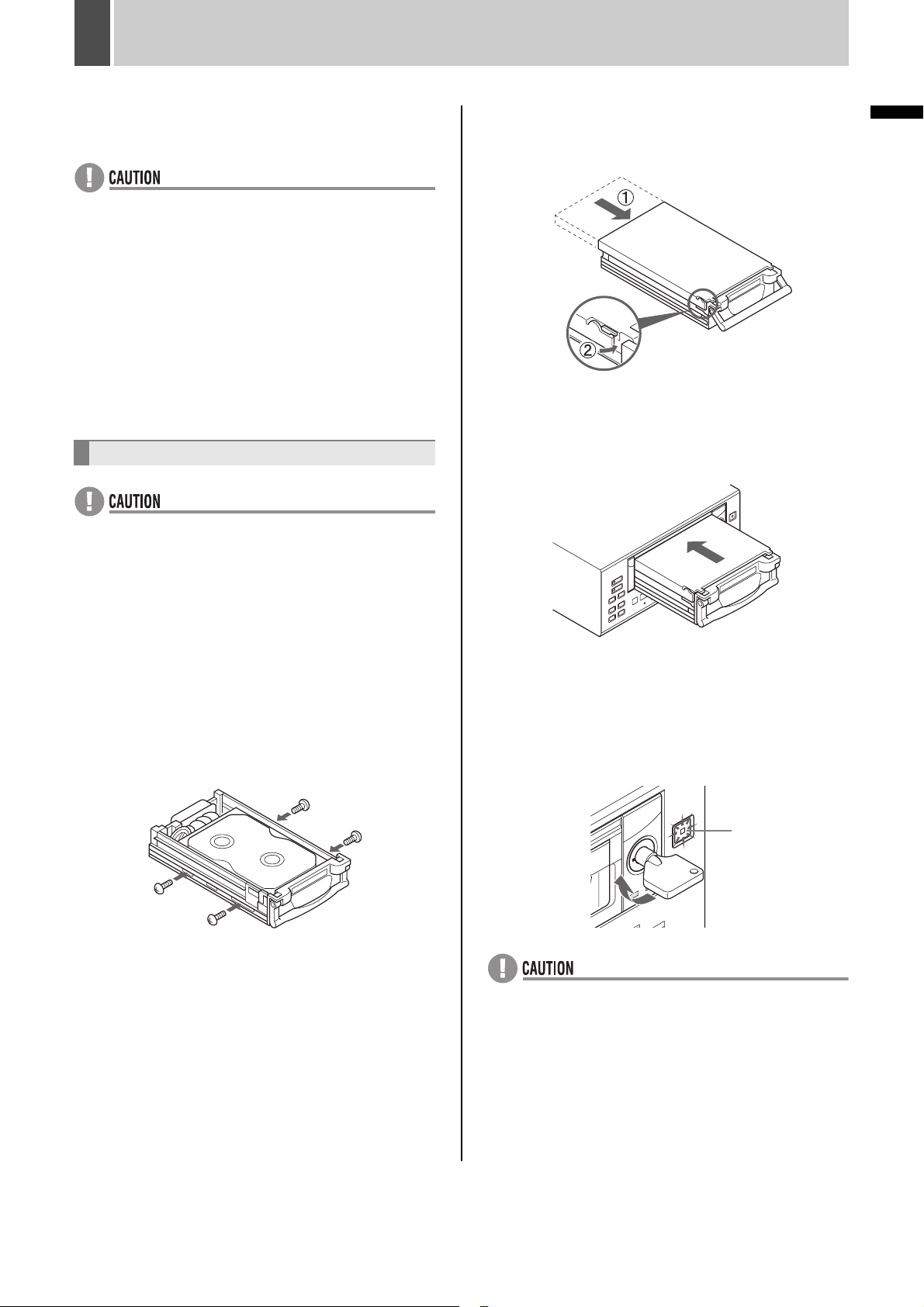
1
Connect the removable HDD’s connector
and place the HDD inside the tray.
Remove the brown antistatic sheet inside the tray.
2 Assemble and tighten the 4 screws.
* Screw tightening torque: 0.5 to 0.6 N•m
Use a non-slip torque screwdriver.
5 Insert the tray release key, turn it in the
direction of the arrow, and then press
the [CHANGE DISK] button.
The HDD indicator will light up and the CHANGE DISK
indicator will switch from green to red.
CHANGE DISK
indicator
z
Always remove the HDD from the recorder when
attaching it to the removable HDD tray and transporting it.
z Correct operation cannot be guaranteed with HDDs not
recorded to using a DSR-300P. If you want to use a
HDD that has been recorded on by a different DVR, be
sure to initialize it before use.
z Even if the tray to which the HDD has been attached is
connected directly to a PC, the playback of images will
not be possible.
10 English
Page 12
REPLACING A REMOVABLE HDD2
Removal
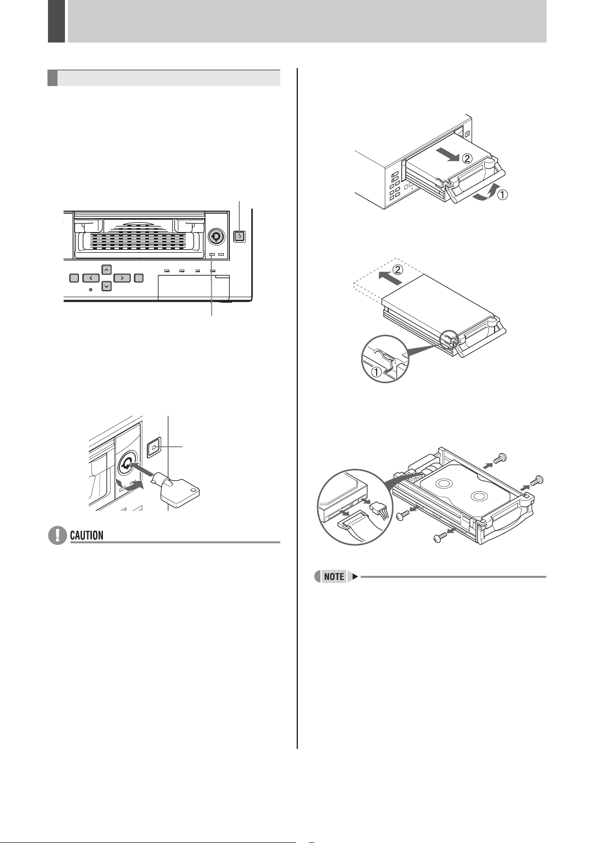
1 With the power turned on, press and
hold the [CHANGE DISK] button for at
least 2 seconds.
The CHANGE DISK indicator changes from red to flashing
green, then lights steadily after 10 seconds. A buzzer
sounds intermittently in time with the indicator’s flashing.
The HDD indicator turns off.
[CHANGE DISK] button
HDD indicator
2 When the CHANGE DISK indicator
lights in green and the HDD indicator
turns off, insert the tray release key and
turn it in the direction of the arrow.
3 Pull the HDD tray out using the handle.
Pulling the handle causes the HDD tray lock to be
released.
4 Release the clasp and remove the
cover.
This action will cause the HDD tray lock to be released.
CHANGE DISK
indicator
z
An alarm will be sounded if the tray release key is turned
when the CHANGE DISK indicator is lit in red or before
the HDD indicator has turned off. Do not remove the HDD
tray while such an alarm is sounding. Failure to observe
this precaution can result in data being damaged.
z Do not forcibly pull out the HDD tray when the tray
release key is ON as this will result in the tray being
damaged.
z If you cannot turn the tray release key when installing
the HDD tray, the HDD tray may have shifted.
Reposition the HDD tray properly.
z Because data might be damaged, a warning tone will
sound if the tray release key is turned without pressing
the [CHANGE DISK] button while the power is on.
If the HDD is removed without using the [CHANGE DISK]
z
button, there is a danger that recorded data may be lost.
z The [CHANGE DISK] button is disabled during
recording or timer recording stanby.
5 Remove the 4 screws, take the
removable HDD out of the tray, and
release the connector.
z Whenever the unit is to be transported, ensure that the
HDD tray is removed from the unit and packaged
separately.
z Periodically check so that screws are tightened and the
plug is secured.
English 11
Page 13
3 NAMES AND FUNCTIONS OF PARTS
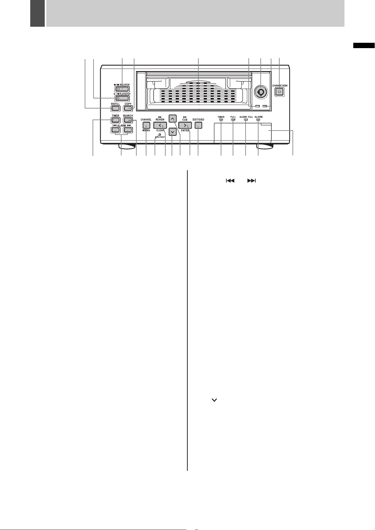
Front panel
12 659
10
1. [STILL] button
Pauses the screen image when pressed during playback.
Pressing the button again restarts playback.
2. [PLAY/STOP] button and indicator
Plays back the normal image (indicator lights). When
pressed during playback, stops playback.
3. [REC/STOP] button and indicator
Starts normal recording. Indicator lights during recording.
During recording, pressing the button for at least 2
seconds stops recording and turns off the indicator.
4. [COPY] button (JP. 35)
Copies images to the hard disk’s archive area, to a
CompactFlash card, or to a Microdrive.
5. Removable HDD tray
6. HDD indicator
Lights up to indicate that data transfer between the unit
and HDD is enabled.
7. Tray release key
Turns power supply to the HDD ON and OFF. When the
key is turned clockwise, the HDD indicator will light up
indicating the ON condition. When OFF, the tray can be
removed. See caution for the key operation. (JP. 11)
8. HDD access indicator
Lights up to indicate the reading or writing of data.
9. [CHANGE DISK] button and indicator (JP. 17)
The red indicator lights when the power is turned ON.
When this button is held down for 2 seconds, the green
indicator flashes then lights, and the HDD can be
removed. If an HDD or fan error occurs, the red indicator
flashes.
3 78
4
11 13 14 20 21 22191712 181516 23 24
INTRODUCTION
11. [ALARM] button (JP. 29)
When the [ ] or [ ] button is pressed during
playback, the unit skips to the next earlier or later alarm.
12. [SEARCH] button (JP. 28)
z When the button is pressed while recording or stopped,
the search setting screen is displayed.
z When the button is pressed during the playback of
frame-recorded images, the playback mode is toggled
between Frame and Field.
13. [MENU] button
Used to display the menu screens.
[CHANNEL] button (JP. 27)
When a multiplexer capable of decoding channel
information (i.e., camera numbers) is connected to the
unit, a channel can be specified for single-channel
playback using this button.
14. [MENU RESET] button (JP. 42)
Used to initialize the currently displayed sub-menu
settings.
In addition, this button can also be pressed while the
normal screen is displayed to make time adjustments.
15. [REVIEW/CLEAR] button (JP. 25)
When pressed during playback, lets you fast-rewind the
image while watching it on-screen. When pressed while
the image is still, reverse playback is performed. Also used
for menu screen operations.
16. [ ] button
Used to move the cursor in menu screens down. Also used
to change setting values.
Used for frame advance (reverse) and adjusting the CUE/
REVIEW speed.
10. [TIMER] button (JP. 22)
When pressed while recording is stopped, the unit enters
timer record standby. When the set time arrives, the digital
video recorder starts timer recording.
12 English
Page 14

NAMES AND FUNCTIONS OF PARTS3
17. [ ] button
Used to move the cursor in menu screens up. Also used to
change setting values.
Used for frame advance (forward) and adjusting the CUE/
REVIEW speed.
18. [CUE/ENTER] button
When pressed during playback, lets you fast-forward the
image while watching it on-screen. When pressed while
the image is still, forward playback is performed. Also used
for menu screen operations.
19. [EXIT/OSD] button (JP. 19)
z Returns the display to the normal screen when the main
menu, a sub-menu, or a setting screen is displayed.
z If pressed repeatedly during recording or playback, the
operation display can be moved or hidden.
20. TIMER indicator (JP. 22)
The indicator lights when the unit enters timer record
standby.
21. FULL indicator (JP. 22)
The indicator begins to flash when the remaining available
memory in the hard disk’s normal recording area reaches
the setting value.
When the recording area becomes full, this indicator turns
on and recording will be stopped.
22. ALARM FULL indicator (JP. 56)
The indicator begins to flash when the remaining available
memory in the hard disk’s alarm recording area reaches
the setting value.
When the recording area becomes full, this indicator turns
on and recording will be stopped.
23. ALARM indicator
Flashes when recording an alarm image. Indicator lights
during pre-alarm recording.
24. CompactFlash card slot (JP. 37)
Used to insert a CompactFlash card or Microdrive.
English 13
Page 15
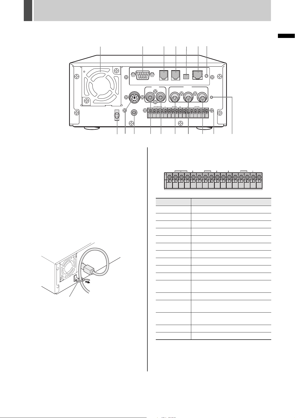
NAMES AND FUNCTIONS OF PARTS3
Rear panel
12 63
DC IN
REMOTE
10
98 17
1. Fan
2. RS-232C terminal (when option board is installed)
3. RS-485 terminal A (when option board is installed)
4. RS-485 terminal B (when option board is installed)
45
RS232C
RS485
AUDIO
OUTIN
NON-REC
ALARM
RESET
OUT OUT OUT OUT OUTOUT FULL FULLCOM COM COMIN IN
COM IN
RS485
BA
TERMINATE
OFF ON
VIDEO
LOOP OUT
IN
CLOCK
WARNING ALARM SERIES
11 13 1412 15 16
15. VIDEO OUT terminal
16. Control and alarm terminals
NON-REC
ALARM
LAN
7
OUT
ALL
RESET
SW
CLOCK
WARNING ALARM SERIES
INTRODUCTION
SW
5. RS-485 termination switch (when option board is
installed)
6. LAN terminal (when option board is installed)
7. LAN link indicator (when option board is installed)
8. Power cord holder
Secure the power cord to the holder using the cord tie
(accessory) as shown in the illustration.
Power cord tie
9. AC power socket (AC IN)
10. Wired remote control terminal
11. AUDIO IN terminal
12. AUDIO OUT terminal
13. VIDEO IN terminal
14. VIDEO LOOP OUT terminal
RESET
COM IN
OUT OUT OUT OUT OUTOUT FULL FULLCOM COM COMIN IN
Pin Signal
COM Ground
ALARM IN Alarm input
ALARM RESET IN Alarm reset input
ALARM OUT Alarm output
NON REC OUT Non rec out terminal
COM Ground
CLOCK IN Clock adjust input
CLOCK OUT Clock adjust output
WARNING OUT Warning out terminal
DISK FULL OUT HDD space warning output
ALARM FULL
OUT
Alarm-recording area space warning output
COM Ground
SERIES IN
SERIES OUT
Input terminal used when recording with
multiple digital video recorders connected.
Output terminal used when recording with
multiple digital video recorders connected.
SWITCH OUT Switch output
COM Ground
17. ALL RESET switch
Resets the recorder’s microcomputer. Menu settings are
not reset.
Resets the clock and backup mode setting.
14 English
Page 16
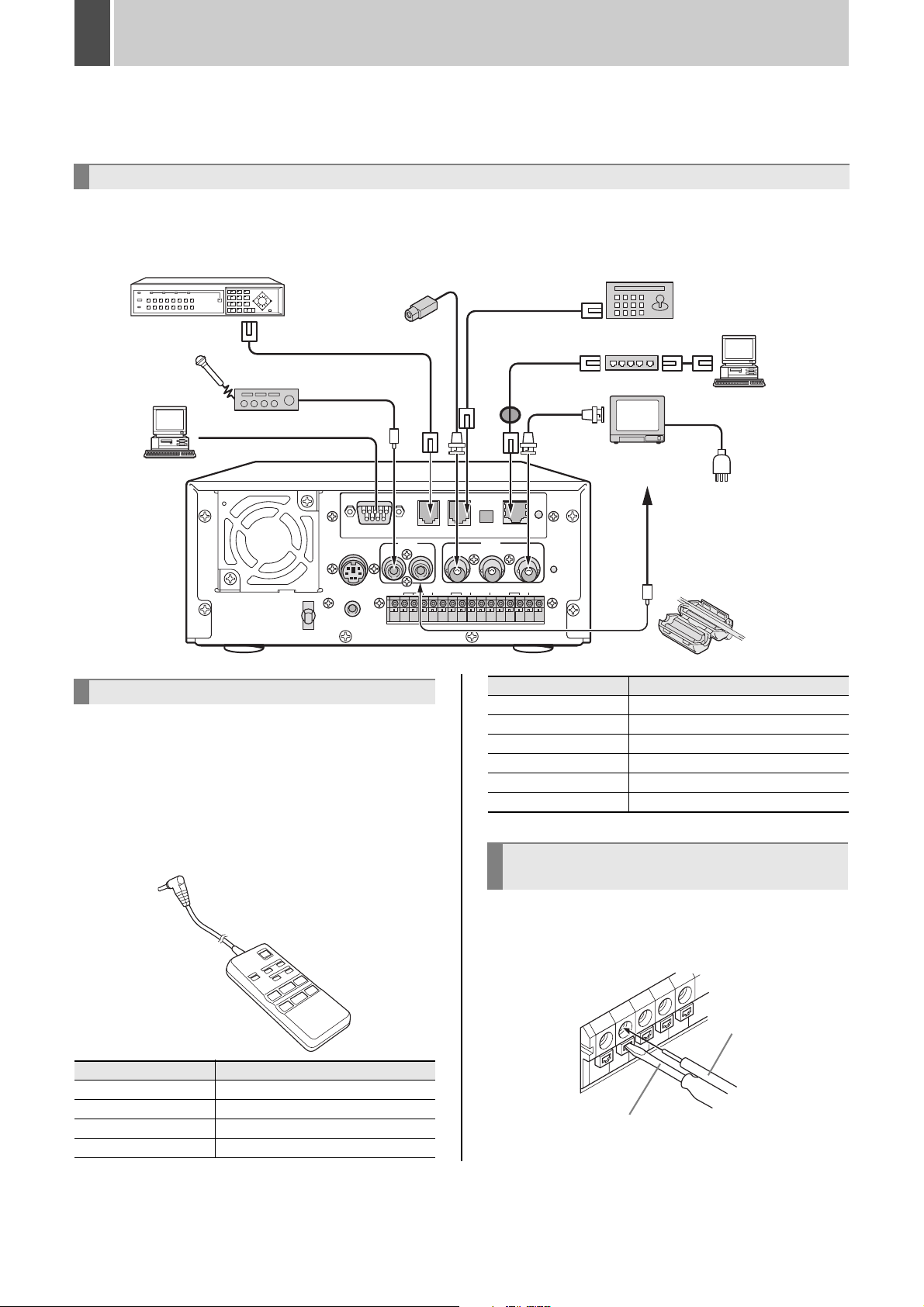
4 INSTALLATION AND CONNECTIONS
This section describes how to connect the digital video recorder to the CCTV camera and other devices. Be sure to read the
instruction manuals for each connected device. Improper connections can cause smoke or malfunctions.
Basic connections
The connections for the camera, TV monitor, system controller, multiplexer, microphone, and PC are shown below.
Multiplexer (sold separately)
* When controlling the multiplexer from a system controller
CCTV camera
(sold separately)
Microphone
(sold separately)
Amp (sold separately)
PC
RS232C
DC IN
REMOTE
AUDIO
COM IN
ALARM NON-REC
RESET
Connecting a remote control circuit
The connections for a remote control circuit are shown
below. Making the connections shown below lets you
operate the digital video recorder by remote control.
z Connect the cable of the wired remote control (VA-
RMN01, sold separately) to the wired remote control
terminal.
The DSR-300P will function as follows in response to
VA-RMN01 key operations.
RS485
RS485
BA
TERMINATE
OFF ON
VIDEO
LOOP OUT
IN
OUTIN
CLOCK
WARNING ALARM SERIES
OUT OUT OUT OUT OUTOUT FULL FULLCOM COM COMIN IN
System controller (sold separately)
Switching HUB
*
PC
Video
input terminal
To audio input
LAN
terminal
* Wrap the ferrite core once
around the LAN connection
OUT
ALL
RESET
cable before attaching the
cable. (Packaged together
with the option RS-485/
SW
VA-RMN01 key DVR operation
REW/REVIEW REW/REVIEW
PLAY PLAY
FF/CUE FF/CUE
REVERSE EXIT/OSD
STOP STOP
PAUSE/STILL PAUSE/STILL
232C/LAN interface board.)
Connecting cables to the control and
alarm terminals
VA-RMN01
VA-RMN01 key DVR operation
REC REC
MENU MENU
↓ SHIFT/SHIFT → TIMER/SEARCH
↓ REC/PLAY SPEED ↑↓ / ↑
English 15
(1) Insert the cable while pushing in the lock pin using a
flat-blade screwdriver.
(2) Remove the screwdriver to secure the cable in place.
Cable
Flat-blade screwdriver
Page 17
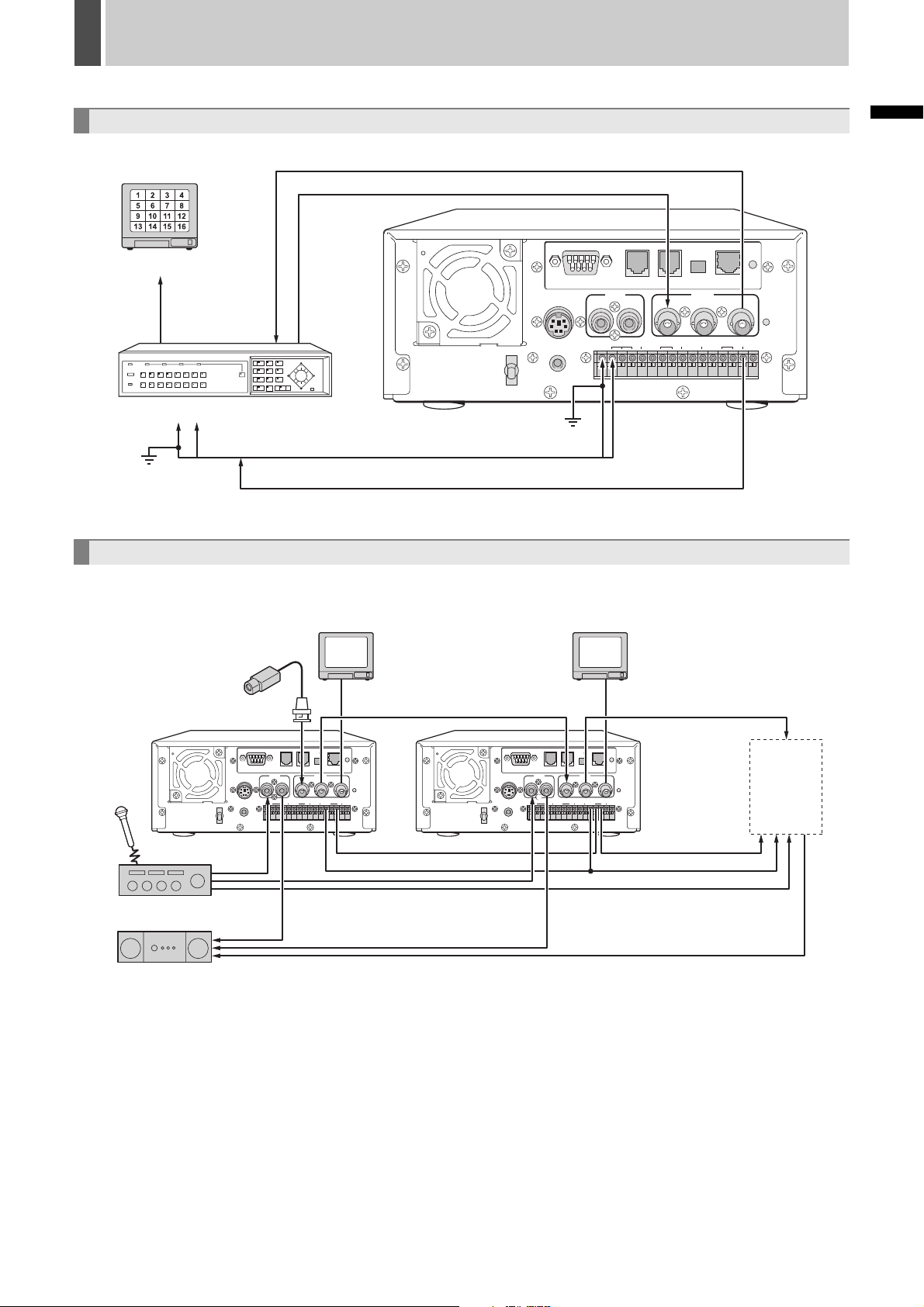
INSTALLATION AND CONNECTIONS4
Connecting a multiplexer
Monitor (sold separately)
Analog
input
Analog
output
Multiplexer (sold separately)
Alarm output terminal
Ground (C)
Switch input terminal
Making analog series connections
DC IN
REMOTE
RS232C
COM IN
RS485
AUDIO
OUTIN
ALARM NON-REC
CLOCK
RESET
OUT OUT OUT OUT OUTOUT FULL FULLCOM COM COMIN IN
Alarm input
terminal
Switch output terminal
RS485
BA
TERMINATE
OFF ON
VIDEO
LOOP OUT
IN
WARNING ALARM SERIES
INTRODUCTION
LAN
OUT
ALL
RESET
SW
CCTV camera
(sold separately)
Amp (sold separately)
Amp (sold separately)
Monitor (sold separately) Monitor (sold separately)
RS485
AUDIO
OUTIN
ALARM NON-REC
CLOCK
RESET
OUT OUT OUT OUT OUTOUT FULL FULLCOM COM COMIN IN
To Series in
RS485
LAN
BA
TERMINATE
OFF ON
VIDEO
OUT
LOOP OUT
IN
WARNING ALARM SERIES
SW
To Common To Common
REMOTE
RS485
LAN
RS485
AUDIO
OUTIN
ALARM NON-REC
RESET
OUT OUT OUT OUT OUTOUT FULL FULLCOM COM COMIN IN
COM IN
BA
TERMINATE
IN
CLOCK
WARNING ALARM SERIES
OFF ON
LOOP OUT
VIDEO
OUT
ALL
RESET
SW
RS232C
DC IN
RS232C
DC IN
REMOTE
COM IN
To Series out
To Common
To 3rd
ALL
RESET
and subsequent
DVRs
To Series inTo Series out
16 English
Page 18
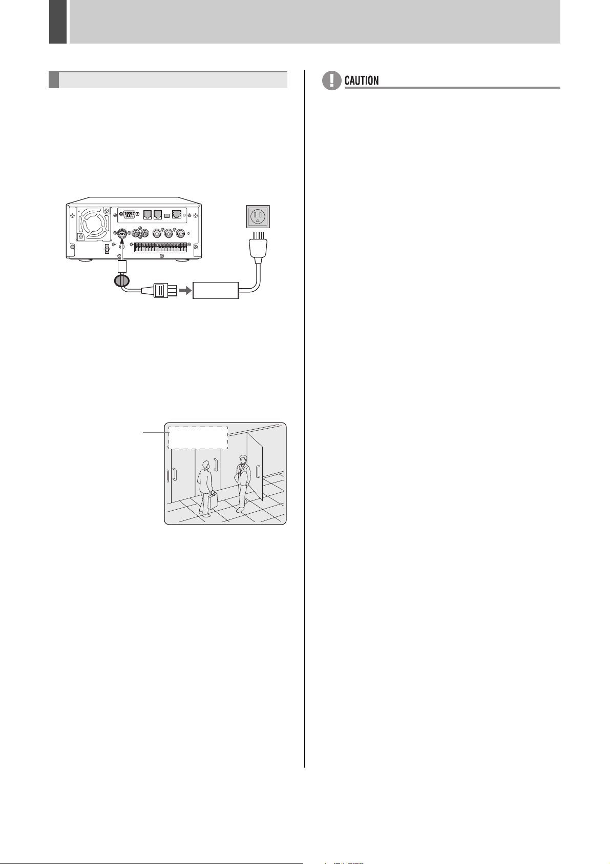
INSTALLATION AND CONNECTIONS4
Connecting the power cord
1 When you have finished making all the
other connections, insert the power
plug into the wall outlet.
There is no power switch. The display indicators flash, and
after a few moments, the monitor screen displays the
camera image.
*
* Attach the supplied ferrite core to the base of the
power cable (coiling not necessary).
z When turning the power ON for the first time
“PLEASE SET THE CLOCK” is displayed on the
monitor screen. Follow the procedures on P. 21 to set
the clock.
z If the clock is already set
The operation display area is displayed.
z If the CHANGE DISK indicator is flashing in red
The digital video recorder has a self-check function that
indicates problems. If there is a problem at power ON or
during operation, the type of problem is indicated by
how rapidly the CHANGE DISK indicator flashes.
Contact a Sanyo Authorized Service Centre if the
CHANGE DISK indicator flashes.
4 flashes per second:
The hard disk is checked automatically at power ON.
If a hard disk problem is found, the CHANGE DISK
indicator flashes, and the hard disk must be replaced
or reformatted. If you need to save images stored on
the disk, contact a Sanyo Authorized Service Centre.
1 flash per second:
Fan problem
z If you disconnect the power cable
Do not move the recorder or subject it to vibration for at
least 30 seconds after turning OFF the power.
The disk in the hard disk drive briefly keeps spinning
after power OFF due to inertia, during which time the
head is unstable. At this time, the disk is sensitive to
shocks or vibrations, so avoid even light shocks.
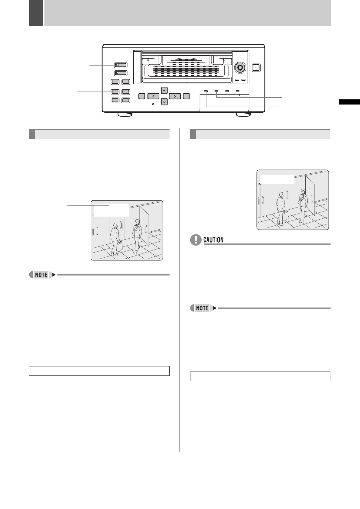
Operation
display area
01- 01-04
00: 00: 00 EN 8.33FPS
English 17
Page 19
1 PREPARING FOR USE
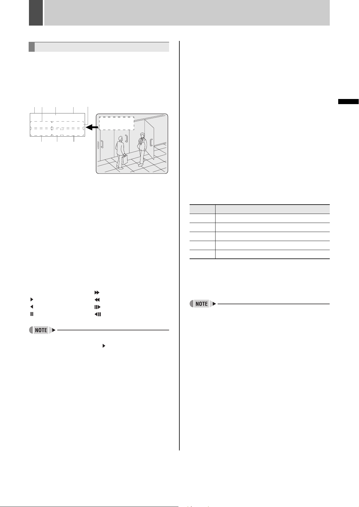
Operation display area
Whenever the power is turned ON, the operation display
area will be displayed at the top left of the monitor screen.
This area indicates the date and time, the image quality,
the recording rate, and other information needed for
operation.
(1) (2)
CH 4
10-05-04 ALARM 0001
10:50:00 EN 8.33FPS
(1) Camera number display (JP. 27)
Displayed when a camera number has been specified for
playback.
(Only in cases where a multiplexer capable of decoding
channel information is connected to the unit.) (JP. 51)
(2) Date display (JP. 21)
Shows the day/month/year.
(3) Operating symbol display
Displays the current operation (such as recording or
playback).
: Recording : Fast-forward playback
: Playback : Fast-rewind playback
: Reverse playback : Slow playback
: Still : Reverse slow playback
z During simultaneous recording and playback, the
(3) (4) (5)
z
100
%
(6) (7)
01-01-04 (day-month-year)
display indicates playback ( ).
(8)
01- 01- 04 ALARM 0001
00: 00 : 00 EN 8.33FPS
z
(5) Alarm display and alarm count display (JP. 23)
When you set an alarm using the “ALARM REC MODE
SET” menu item, the alarm display area displays the
following information.
z When alarm recording is set;
“ALARM” is displayed.
“ALARM” is flashed during alarm recording.
z When pre-alarm recording is set;
“PRE” is displayed.
When an alarm occurs, “PRE” disappears, “ALARM” is
displayed, and the number of alarms is shown. The total
number is indicated in the alarm display.
z When performing playback from the archive area;
“ARCHIV” is displayed.
(6) Time display (JP. 21)
“00:00:00” is displayed when you turn the power ON for
the first time. The digital video recorder uses the date and
time to manage recording and playback points.
(7) Image quality display (JP. 58)
Displays the quality of the image that can be recorded on
the hard disk. Set to “EN” (Enhanced) in the default
settings.
Setting Description
SF Super Fine
FI Fine
EN Enhanced
NO Normal
BA Basic
(8) Recording rate display (JP. 45)
Displays the recording rate that can be recorded on the
hard disk. The default setting is 8.33 FPS (for field
recording).
z Although operations such as playback, copying, and
data transfer are possible while recording, this unit
gives priority to recording and other operations may be
delayed as a result. Communication may be cut off in
some cases.
OPERATION
(4) Remaining memory in recording area (JP. 56)
Displays the remaining memory as a percentage when
overwriting in the normal recording area or the alarm
recording area is forbidden. To change the remainingmemory display format, follow the instructions in “4.
RECORDING CONDITIONS SET” from the menu.
18 English
Page 20
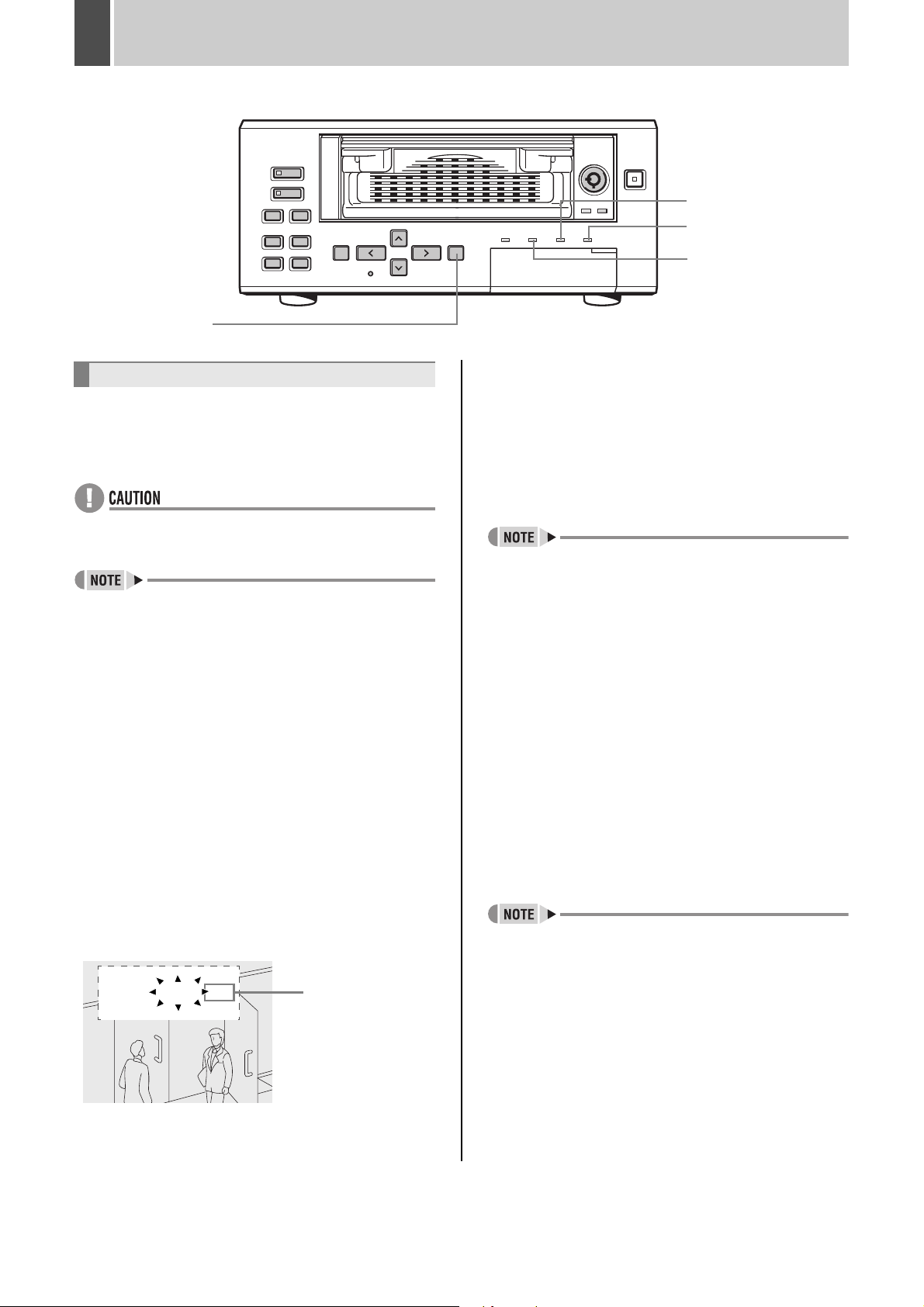
PREPARING FOR USE1
Changing the position of the
operation display area
[EXIT/OSD] button
[A]
[B]
[C]
[A] Normal recording area
1 Press the [EXIT/OSD] button repeatedly.
Pressing the [EXIT/OSD] button repeatedly lets you move
or erase the operation display area.
Example: Normal screen
Operation
display area
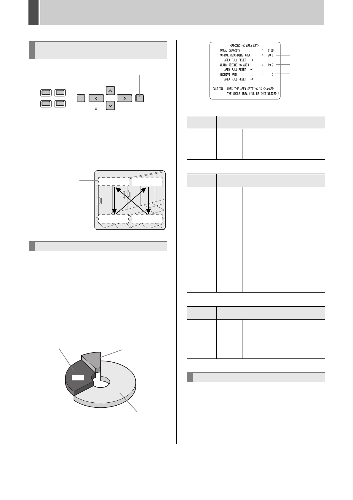
Built-in hard disk
Hard disk recording area
z When an unused hard disk is installed, the initial
recording area settings (normal recording area 80%,
alarm recording area 19%, archive area 1%) are
automatically set at recorder power ON.
z When a hard disk with set recording areas is installed,
the set recording areas are used for recording.
You can check the recording areas of a set hard disk by
selecting “3. RECORDING AREA SET” from the menu.
z When installing a hard disk that was used by another
DVR, check the recording area settings.
[B] Alarm recording area
01- 01 -04
00:00:00EN 8.33FPS
1%
[C] Archive area
Recording
mode
Normal
recording
Timer
recording
Manual
Automatic
During monitoring, recording is
performed when the [REC/STOP]
button is pressed.
Recording is carried out in
accordance with timer settings.
[B] Alarm recording area
Recording
mode
Recording is carried out in
accordance with alarm recording
settings. Specifically, alarm images
Alarm
recording
Pre-alarm
recording
Automatic
Automatic
are recorded in the alarm recording
area in response to operation of the
switch that has been installed for the
alarm input terminal or to detection of
an intruder or the like using motion
sensors.
Recording is carried out in
accordance with pre-alarm settings.
Specifically, the same images as
recorded normally over a preset time
interval are repeatedly overwritten in
the alarm recording area until an
alarm occurs. Pre-alarm recording
can be setup to have the digital video
recorder record alarm images before
an alarm input is detected.
[C] Archive area
Recording
mode
This area is used to copy important
images from the normal recording
area and alarm recording area. By
Copy Manual
making changes to the normal
recording area and the alarm recording area, this area can be extended to
up to 10 GB automatically.
Recording method
Recording method
Recording method
19%
80%
[A] Normal recording area
Hard disk’s recording area
English 19
Selecting the recording method
z If you want to record images while monitoring; ......P. 22
z If you want to record with an end time specified
using timer settings;................................................P. 22
z If you only want to record when an intruder is
present;.............................................................P. 23, 66
z If you also want to record images from before the
intruder appears; ....................................................P. 24
Page 21
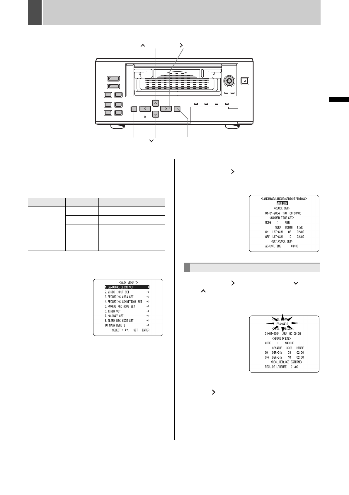
2 SETTING THE LANGUAGE/CLOCK
[ ] button
[MENU] button
This section describes how to set the language displayed
on the monitor and how to set the digital video recorder’s
internal clock.
[Settings] ( indicates default setting.)
Item Setting Description
ENGLISH Sets the language to English.
(1)LANGUAGE
SET
(2)CLOCK SET Sets the date and time.
ESPAÑOL Sets the language to Spanish.
DEUTSCH Sets the language to German.
FRANCAIS Sets the language to French.
[ ] button
[ ] button
OPERATION
[EXIT/OSD] button
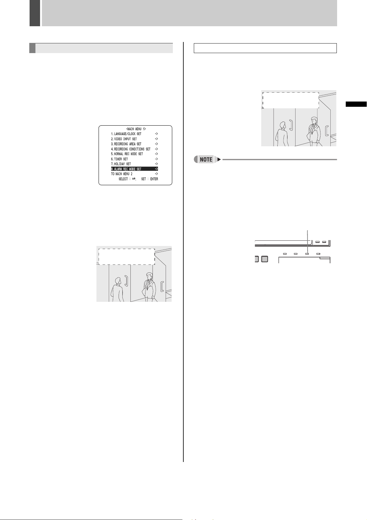
2 Select “1. LANGUAGE/CLOCK SET” and
press the [ ] button.
The <LANGUAGE/LANGUE/SPRACHE/IDIOMA> screen
is displayed with the cursor positioned on “ENGLISH”.
1 Press the [MENU] button.
The <MAIN MENU 1> screen appears.
To change the language
3 Press the [ ] button, then the [ ] or
[ ] button to select the desired
language.
The set item flashes.
4 When you have made a selection, press
the [ ] button.
The cursor moves to the date and time.
The language has now been set.
To return to the normal screen, press the [EXIT/OSD]
button.
20 English
Page 22
SETTING THE LANGUAGE/CLOCK2
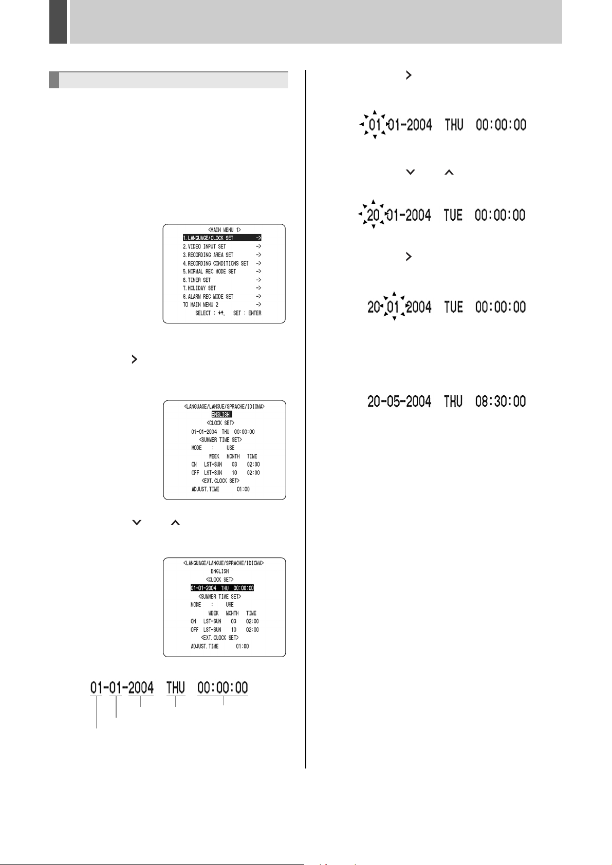
Setting the time
(Default setting: 01-01-2004 THU 00:00:00)
Be sure to set the correct date and time. The digital video
recorder stores the times of recordings for use in
operations such as playback and search/playback.
Example: Setting 20 May 2004, 8:30
1 Press the [MENU] button.
The <MAIN MENU 1> screen appears.
2 Select “1. LANGUAGE/CLOCK SET” and
press the [ ] button.
The <LANGUAGE/LANGUE/SPRACHE/IDIOMA> screen
is displayed. The cursor is positioned on “ENGLISH”.
4 Press the [ ] button.
“01” (indicating the day) flashes.
5 Press the [ ] or [ ] button to select
“20”.
6 Press the [ ] button.
“01” (indicating the month) flashes.
7 Use the same procedure to set the
month (5 in this example), year (2004),
hour (08), and minute (30).
3 Press the [ ] or [ ] button to move
the cursor to the date and time under
<CLOCK SET>.
YEAR WEEK TIME
MONTH
DAY
When you have set the minute, the cursor moves to
“MODE” under <SUMMER TIME SET>, and the clock
starts from 00 seconds.
z “WEEK” is set automatically.
z The time is stopped during clock setting.
8 Press the [EXIT/OSD] button.
The display returns to the normal screen.
English 21
Page 23
3 NORMAL RECORDING/TIMER RECORDING
[REC/STOP] button
[TIMER] button
Normal recording
Follow the procedures below to record the monitored
image in the normal recording area.
1 Press the [REC/STOP] button.
The REC/STOP indicator lights. “ ” appears on the
screen (i.e., the recording symbol), and recording starts.
Recording
symbol
z When you record for the first time, the default settings
are used. For details regarding changing of the image
quality or recording rate, see P. 58.
z When the space remaining in the normal recording area
drops below the setting value, the FULL indicator lights
and recording stops. You can start recording from the
beginning again by changing the recording setting.
(JP. 56)
z You can record and play back images at the same time.
See
P. 25
for the procedure.
z You cannot change the menu during recording.
z
10- 05- 04
10: 50: 00 EN 8.33FPS
FULL indicator
TIMER indicator
Timer recording
Follow the procedures below to record the monitored
image in the normal recording area at the set time.
1 Press the
[TIMER] button.
The TIMER indicator lights
and the digital video
recorder enters timer
recording standby mode.
z A warning tone sounds if timer recording has not been
set.
(1) See P. 59 for how to set timer recording.
(2) When the time specified in the timer settings arrives,
the REC/STOP indicator lights, “ ” (the recording
symbol) appears in the screen, and recording starts.
(3) When the timer’s end time arrives, the REC/STOP
indicator goes out, and recording stops.
z When the space remaining in the normal recording area
drops below the setting value, the FULL indicator lights
and recording stops. You can start recording from the
beginning again by changing the recording setting.
(JP. 56)
z You can record and play back images at the same time.
See P. 25 for the procedure.
10- 05- 04
10: 50: 00 EN 8. 33FPS
OPERATION
Ending normal recording
2 Press the [REC/STOP] button for at
least 2 seconds.
The REC/STOP indicator goes out and recording stops.
Stopping during timer recording
2 Press the [TIMER] button.
The TIMER indicator turns off and recording stops.
22 English
Page 24
4 ALARM AND PRE-ALARM RECORDING
ALARM FULL indicator
ALARM indicator
FULL indicator
[EXIT/OSD] button
Alarm recording
Follow the procedures below to have the digital video
recorder record an alarm image only when alarm input is
detected.
z Confirm that the cable of the device required for alarms
is connected to the ALARM terminal. (JP. 15)
z When the motion sensor is set, an alarm image is
recorded when a moving subject is detected. (JP. 66)
1 Set alarm recording.
The default settings are shown below.
See P. 63 for how to change these settings.
z “ALARM RECORDING”: “OFF”
Alarm recording is disabled.
z “DURATION”: “1 SEC”
Recording is performed for 1 second for each alarm
signal received while the alarm is set.
2 When alarm input is detected
When an alarm is generated, the display below appears in
the operation display area, and an alarm image is
recorded.
z
10- 05- 04 ALARM 0001
10: 50: 00 EN 8. 33FPS
Counts the number
of alarms.
extended counting from that moment. The new alarm is
not counted.
z The latest 9,999 alarms are displayed in the alarm
history (recording list). (Up to 16,000 items are recorded
in the history.)
z The panel’s ALARM indicator flashes.
z If an alarm occurs during normal recording or timer
recording, the recording operation will be ended.
z When the normal recording area is set to “*1%”, alarm
recording is possible for the complete memory available
in the alarm recording area. For “1%” and other
settings, up to 16,000 items are recorded per hard disk.
However, if set for *1%, “ALARM SEARCH”, “ALARM
THUMBNAIL SEARCH”, and “MOTION DETECTION
SEARCH” will not be available. Use “TIME/DATE
SEARCH” instead.
Furthermore, since the alarm skip function will also be
inactive, it will be necessary to carry out fast-forward
and fast-rewind playback.
3 End alarm recording.
When the alarm duration time ends (default setting: 1
second), “ALARM” disappears from the operation display,
the ALARM indicator stops flashing, and recording stops.
z When the space remaining in the alarm recording area
drops below the setting value, the FULL indicator lights
and recording stops. You can start recording from the
beginning again by changing the recording setting.
(JP. 56)
z “ALARM” appears in the operation display area.
z When an alarm is generated on a channel that is
already alarm recording, the alarm recording time is
English 23
If recording is ended during alarm recording
using the motion sensor
Set “LEVEL” from the motion sensor screen to “OFF”.
(JP. 66)
Page 25
ALARM AND PRE-ALARM RECORDING4
Pre-alarm recording
Follow the procedures below to have the digital video
recorder record an image from before detection of an
alarm and the start of alarm recording.
1 Set pre-alarm recording.
Follow the procedures on P. 63 to set “8. ALARM REC
MODE SET” on the <MAIN MENU 1> screen to “PREALARM RECORDING”.
2 Following this, press the [EXIT/OSD]
button.
The display returns to the normal screen.
“PRE” is displayed in the operation display area and the
ALARM indicator lights. Pre-alarm recording starts (without
displaying a symbol).
If an alarm is detected
Pre-alarm recording is automatically ended and alarm
recording starts.
z “PRE” from the operation display area is replaced by
“ALARM” and the ALARM indicator flashes.
10- 05- 04 ALARM 0001
20: 10: 00 EN 8. 33
z When you record for the first time, the default settings
are used. For details regarding changing of the image
quality or recording rate, see P. 63.
z When the space remaining in the alarm recording area
drops below the setting value, the ALARM FULL
indicator lights and recording stops. You can start
recording from the beginning again by changing the
recording setting. (JP. 56)
ALARM FULL indicator
FPS
OPERATION
10- 05- 04 PRE 0001
20: 10: 00 EN 8. 33
The same monitoring image as in the normal recording
area is recorded in repeated fashion to the alarm recording
area.
FPS
24 English
Page 26
5
Follow the procedures below to playback images stored in the normal recording area (by normal recording or timer recording).
Normal recording area
NORMAL RECORDING/TIMER RECORDING PLAYBACK
[PLAY/STOP] button
[] button
[ ] button
[] button
Playback
1 Press the [PLAY/STOP] button.
The PLAY/STOP indicator lights, and “ ” appears in the
operation display area. The images stored in the normal
recording area are played back.
Operation
display
z Image playback starts from the point at which recording
started.
z If “OVERWRITE” has been set in the normal recording
settings, playback starts with the oldest recorded image
when the recording is played back for the first time.
z When playback ends, the digital video recorder pauses
automatically.
z While stopped, “ ” is displayed in the operation display
area.
z After playback is stopped, it will resume from the
stopped point the next time it is started.
10- 05- 03 ALARM 0001
10- 05- 04 ALARM 0001
10: 50: 00 EN 0. 12SEC
10: 50: 00 EN 8. 33FPS
z
[ ] button
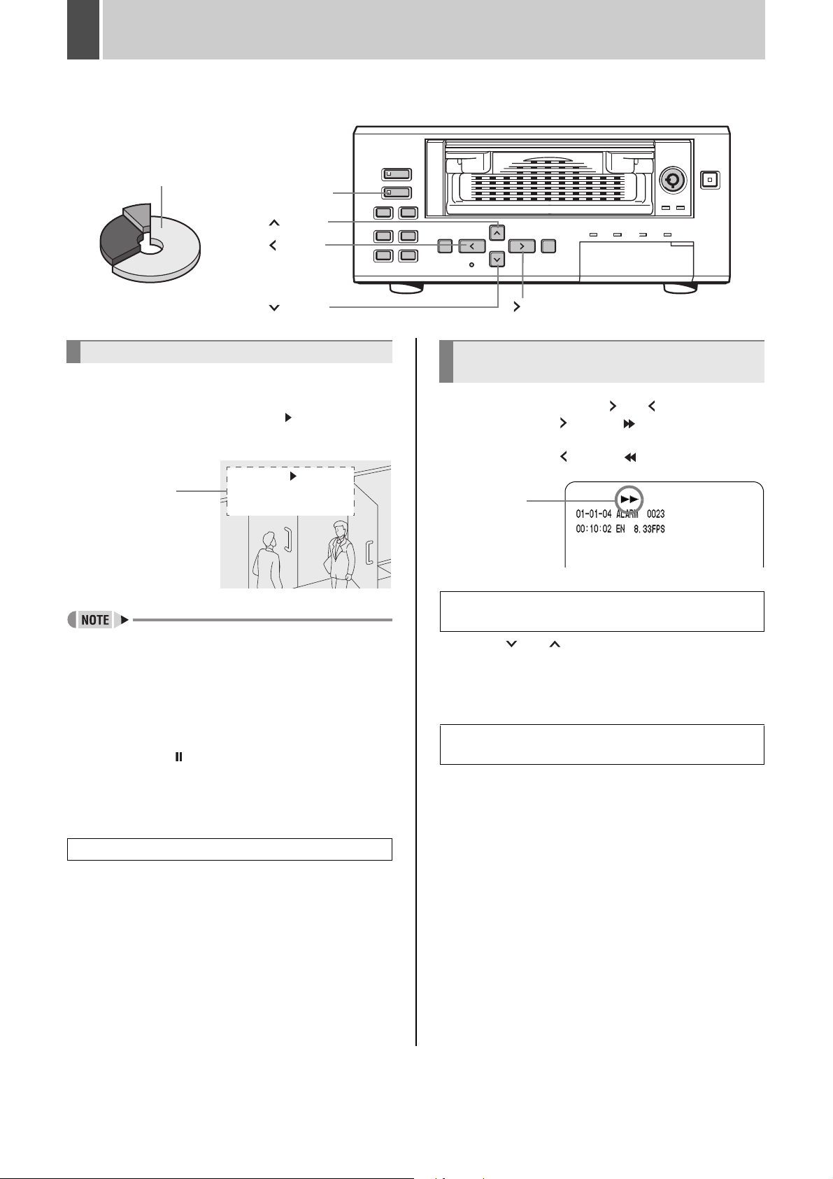
Fast-forward playback/fast-rewind
playback
During playback, press the [ ] or [ ] button.
When you press the [ ] button, “ ” appears in the
operation display, and the playback fast-forwards.
When you press the [ ] button, “ ” appears in the
operation display, and the playback fast-rewinds.
Fast-forward
playback
symbol
To change the fast-forward playback/fastrewind playback speed
Press the [ ] or [ ] button while fast-forward/
rewind.
The speed changes by one increment/decrement each
time you press the button.
Ending fast-forward playback/fast-rewind
playback
Press the [PLAY/STOP] button.
Playback is stopped and live images are displayed.
Ending playback
2 Press the [PLAY/STOP] button.
Playback ends.
Playing back an image near the point of
recording
The digital video recorder prioritizes recording
operations, so the playback image may pause
temporarily.
English 25
Page 27
NORMAL RECORDING/TIMER RECORDING PLAYBACK5
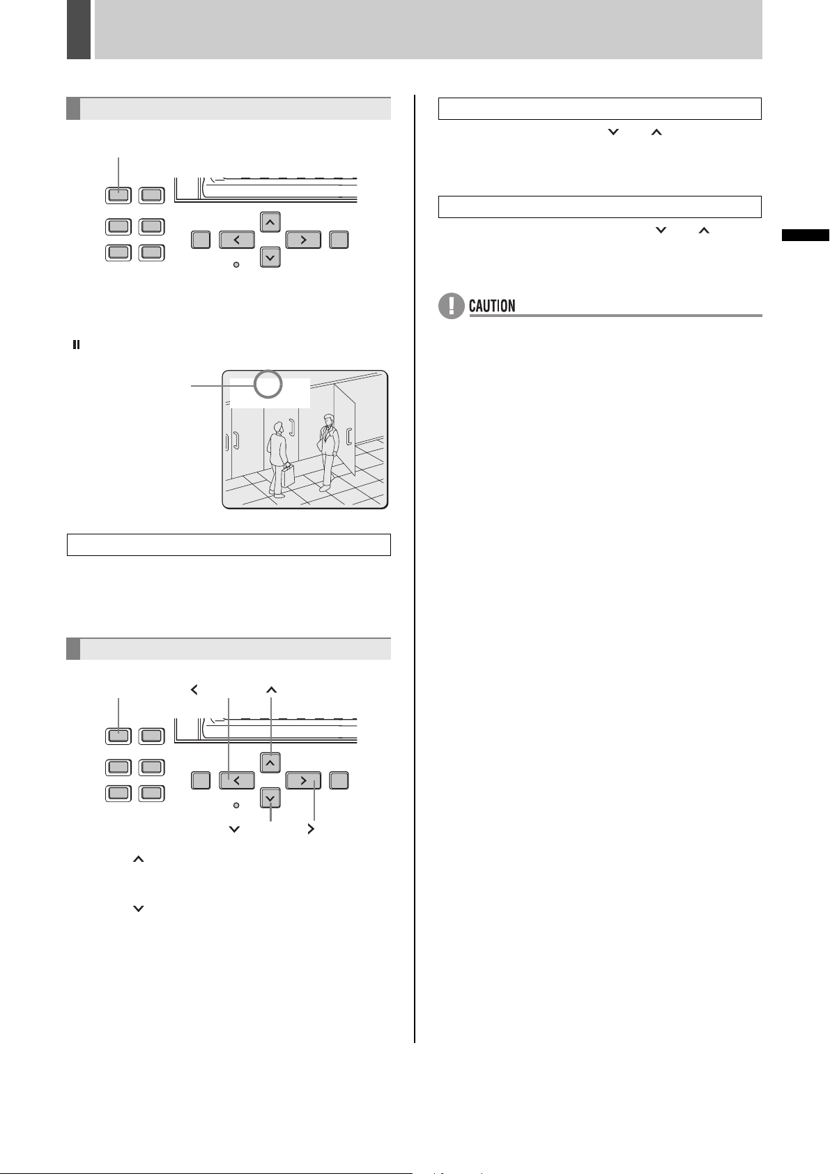
Viewing still images
[STILL] button
1 During playback, press the [STILL]
button.
“ ” appears in the operation display area and the image is
still. The PLAY/STOP indicator flashes in green.
Still symbol
10-05-04
10: 50: 00 EN 8. 33FPS
Slow playback or fast-forward
During playback, press the [ ] or [ ] button.
The speed changes by one increment/decrement each
time you press the button.
Slow reverse playback or fast-rewind
During reverse playback, press the [ ] or [ ] button.
The speed changes by one increment/decrement each
time you press the button.
z When the images from each recording area are played
back in succession, the quality of the picture may drop
momentarily as playback switches from one recording
area to another.
z If normal, fast-forward, or fast-rewind playback is
carried out either for playback during alarm recording or
continuous playback from the normal recording area
and alarm recording area, the image may seem to have
paused in certain cases.
OPERATION
To resume playback
2 Press the [STILL] button.
The PLAY/STOP indicator lights in green.
Frame advance (forward/reverse)
[STILL] button
Press the [ ] button while a still image is displayed.
The still image advances by one frame.
Press the [ ] button while a still image is displayed.
The still image moves back by one frame.
[ ] button
[ ] button
[ ] button
[ ] button
26 English
Page 28
NORMAL RECORDING/TIMER RECORDING PLAYBACK5
Playback with a channel specified for
the camera image
If a multiplexer (sold separately) is connected to this unit
and images are recorded from multiple cameras, you can
specify the number (or channel) of the camera whose
recording is to be played back using the following
procedure.
[CHANNEL] button
z The specification of a channel for playback will only be
possible when a multiplexer capable of decoding the
channel information (i.e., channel number) is
connected.
z When this operation is carried out, only the specified
channel is played back. No other channels will be
displayed.
z When a channel is selected, the multiplexer title
information, date information, and/or time information
may partially disappear.
Switching between frame and field
playback
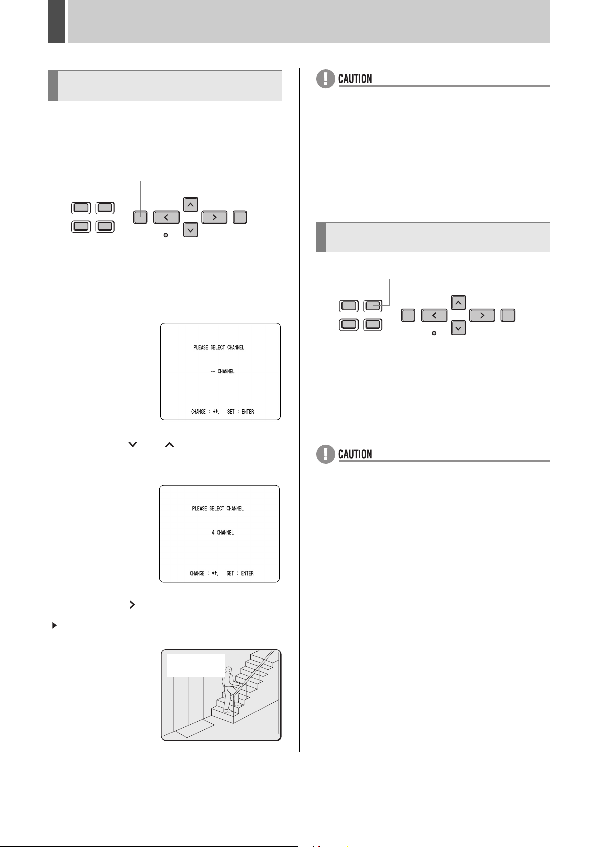
1 Press the [CHANNEL] button while a
still image is displayed.
A screen allowing you to select the number of a camera
connected to the multiplexer is displayed.
2 Press the [ ] or [ ] button to specify a
channel.
(Example: Camera 4)
[SEARCH] button
1 Press the [SEARCH] button while the
digital video is playing back framerecorded images.
Each time you press the button, the screen toggles
between frame and field playback.
z Switching between frame and field playback can only
be carried out for frame-recorded images.
z Fast-moving images that have been frame recorded
may appear shaky during playback.
3 Press the [ ] button.
“ ” appears in the operation display area and the images
from the specified channel are played back.
CH4
10-05- 04
20: 10: 00 EN 8. 33
English 27
FPS
Page 29
6 SEARCHING FOR RECORDED IMAGES
0011
Images stored in the alarm recording area or archive area
can be located by searching and then played back. Five
different search methods are available.
Archive area
Alarm recording area
[SEARCH] button
[ALARM] button
Image to search for
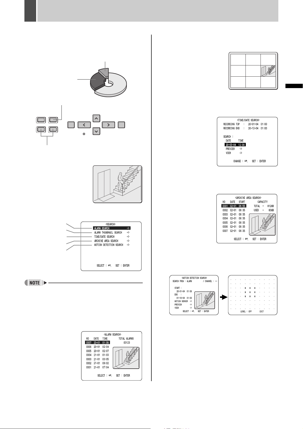
(2) ALARM THUMBNAIL SEARCH (JP. 30)
Lets you search and play back alarm images using
thumbnails.
0016 0015 0014
0011
0013 0012
0010 0009 0008
0011
(3) TIME/DATE SEARCH (JP. 30)
Lets you search and play back recorded images by date/
time.
(4) ARCHIVE AREA SEARCH (JP. 32)
Lets you search and play back recorded images stored (or
copied) to the archive area.
OPERATION
Search in <SEARCH> screen
(1)
(2)
(3)
(4)
(5)
z You can use the button operations to pause, fast-
forward, or perform other operations on retrieved
images being played back.
(1) ALARM SEARCH (JP. 29)
Lets you search and play back alarm images from the
recording list.
(5) MOTION DETECTION SEARCH (JP. 32)
Lets you search and play back recorded images of moving
objects detected by motion sensors.
28 English
Page 30
SEARCHING FOR RECORDED IMAGES6
ALARM SEARCH
Lets you search and play back all the alarm images stored
in the alarm recording area. If pre-alarm images are being
recorded, playback will start from immediately before the
alarm.
[SEARCH] button
[ALARM] button
[ ] button [ ] button
[ ] button
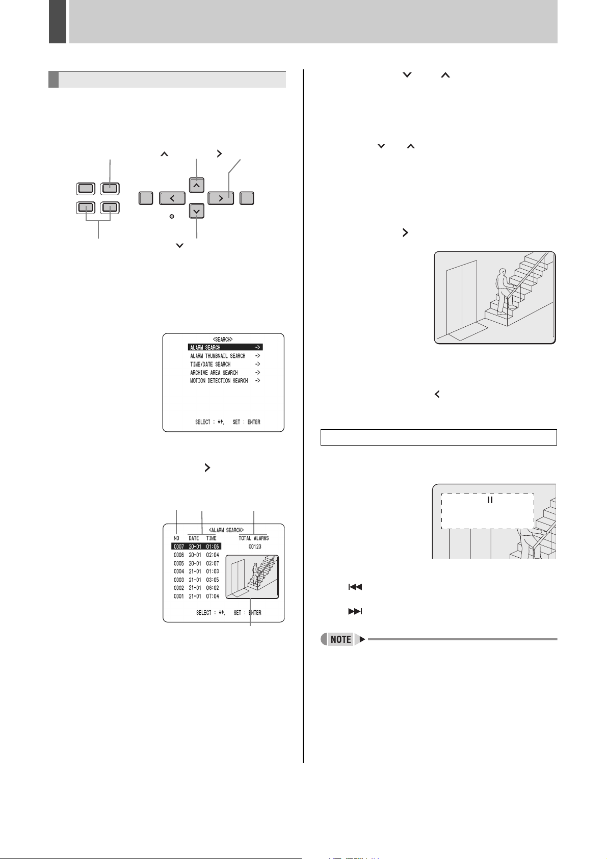
1 Press the [SEARCH] button while the
digital video recorder is recording or
stopped.
The <SEARCH> screen is displayed.
3 Press the [ ] or [ ] button to select
the image to play back.
The selected alarm image is displayed in the preview
screen. You can display up to 8 alarm images.
z To display the next (previous) image
Press the [ ] or [ ] button.
z To display the items on the next page
Press the [ALARM] button. The next 8 items are
displayed chronologically.
z To end search mode
Press the [SEARCH] button.
4 Press the [ ] button.
The selected image is
played back on the full
screen.
To display pre-alarm images
After starting playback of alarm images found using an
alarm search, press the [ ] button to activate reverse
playback.
2 Check that “ALARM SEARCH” is
selected, and press the [ ] button.
The <ALARM SEARCH> screen is displayed.
(1) (3)
(2)
(4)
(1) NO:
Displays the alarm number.
(2) DATE/TIME:
Displays the date/time at which the alarm was received
and the image recorded.
(3) TOTAL ALARMS:
Displays the total number of recorded alarm images.
(4) Preview screen:
Displays the selected alarm image.
Skipping can be carried out during playback
1 During playback, press the [ALARM]
button.
20- 05- 04 ALARM 0003
01: 06: 00 EN 8. 33
z Playback will skip to the next earlier alarm image when
the button is pressed.
z Playback will skip to the next later alarm image when
the button is pressed.
z When playback is performed using an alarm search, the
image at the start and end of each alarm recording will
be paused.
Play the final alarm image using the [ALARM] button.
FPS
English 29
Page 31

SEARCHING FOR RECORDED IMAGES6
0011
ALARM THUMBNAIL SEARCH
All alarm images stored in the alarm recording area can be
displayed as thumbnails.
[SEARCH] button [ ] button [ ] button
[ ] button
1 Press the [SEARCH] button while the
digital video recorder is recording or
stopped.
The <SEARCH> screen is displayed.
2 Press the [ ] or [ ] button to select
“ALARM THUMBNAIL SEARCH”.
5 Press the [ ] button.
The selected image is played back on the entire screen.
z In the same way as for alarm searching, playback is
only possible within each alarm recording. Play the
previous or subsequent alarm image using the
[ALARM] button.
TIME/DATE SEARCH
Follow the procedures below to play back an image
recorded in the hard disk’s normal recording area (i.e.,
normal recording and timer recording images) or alarm
recording area by specifying its date and time.
[SEARCH] button [ ] button [ ] button
OPERATION
3 Press the [ ] button.
The 9 most-recent alarm images are displayed.
An alarm number is indicated in each alarm image, and the
number of the currently selected alarm will flash.
0016 0015 0014
0013 0012
0010 0009 0008
0011
0011
4 Press the [ ] or [ ] button to move
the cursor and select the image to play
back.
[ ] button
1 Press the [SEARCH] button while the
digital video recorder is recording or
stopped.
The <SEARCH> screen is displayed.
2 Press the [ ] or [ ] button to select
“TIME/DATE SEARCH”.
The alarm number for the selected image will start to flash.
z To display the image on the next (previous) page
Press the [ALARM] button. The image of the next
(previous) page is displayed as a thumbnail.
z To end search mode
Press the [SEARCH] button.
30 English
Page 32

SEARCHING FOR RECORDED IMAGES6
3 Press the [ ] button.
The <TIME/DATE SEARCH> screen is displayed.
The cursor is positioned on the date and time item.
(1)
(2)
(3)
(4)
(5)
(1) RECORDING TOP:
Displays the date/time of the image recorded first.
(2) RECORDING END:
Displays the date/time of the image recorded last (latest
image).
(3) SEARCH:
Enter the date/time of the image to play back.
(4) PREVIEW:
Displays the preview screen.
(5) VIEW:
Select this item to play back the image on the entire
screen.
The cursor moves to “PREVIEW”.
5 Press the [ ] button.
Images are searched and a preview is displayed.
z If no image exists for the specified time
The image for the time closest to the specified time is
displayed.
z To end search mode
Press the [SEARCH] button.
4 Press the [ ] button and set the date/
time to search.
Example: To search for the image from 26 October
2004 20:00
26-10-04 20:00
(1) (2) (3) (4) (5)
(1) Press the [ ] or [ ] button to select “26” (the day).
(2) Press the [ ] button, then the [ ] or [ ] button to
select “10” (the month).
(3) Press the [ ] button, then the [ ] or [ ] button to
select “04” (the year).
(4) Press the [ ] button, then the [ ] or [ ] button to
select “20” (the hours).
(5) Press the [ ] button to select “00” (the minutes), then
press the [ ] button.
6 Press the [ ] button to select “VIEW”,
then press the [ ] button.
The selected image is played back on the entire screen.
z The retrieved image can be displayed on the entire
screen without displaying the preview screen by
entering the date and time, and by then selecting
“VIEW”.
z You can use the button operations to pause, fast-
forward, or perform other operations on retrieved
images being played back.
English 31
Page 33

SEARCHING FOR RECORDED IMAGES6
ARCHIVE AREA SEARCH
Follow the procedures below to playback images from the
archive area.
1 Press the [SEARCH] button while the
digital video recorder is recording or
stopped.
The <SEARCH> screen is displayed.
2 Press the [ ] or [ ] button to select
“ARCHIVE AREA SEARCH”.
3 Press the [ ] button.
The <ARCHIVE AREA SEARCH> screen is displayed.
(1) (2) (3) (4)(5)
MOTION DETECTION SEARCH
By setting images recorded in the hard disk’s normal
recording area (i.e., normal recording and timer recording
images) or alarm recording area to the motion sensor,
variations from these images as a result of the presence of
an intruder or the like can be detected, and the
corresponding images can be played back.
OPERATION
z When performing a motion detection search for a
multiplexer image, set “MULTIPLEXER” from “2. VIDEO
INPUT SET” to anything other than “NO USE”. (JP. 51)
z When a multiplexer capable of decoding channel
information is connected, a camera number (or
channel) can be specified, and the corresponding
camera image can be detected. This type of setting will
not be possible for any other type of multiplexer.
(JP. 27)
1 Press the [SEARCH] button while the
digital video recorder is recording or
stopped.
The <SEARCH> screen is displayed.
(1) NO: Displays the archive number.
(2) DATE: Displays the date of the recorded image.
(3) START: Displays the start time for the recorded
image.
(4) TOTAL: Displays the total capacity of the archive area.
(5) USED: Displays the amount of archive area capacity
currently filled.
4 Press the [ ] or [ ] button to select
the image for playback.
The selected image is displayed in the preview screen.
z To display the next (previous) image
Press the [ ] or [ ] button.
z To end search mode
Press the [SEARCH] button.
5 Press the [ ] button.
The image is played back on the full screen.
2 Press the [ ] or [ ] button to select
“MOTION DETECTION SEARCH”, then
press the [ ] button.
The <MOTION DETECTION SEARCH> screen is
displayed.
3 Press the [ ] or [ ] button to select
“SEARCH FROM”, then press the [ ]
button.
“ALARM” flashes.
[Settings] ( indicates default setting.)
Setting Description
ALARM
NORMAL
ALARM &
NORMAL
Searching will only be performed for images in the
alarm recording area.
Searching will only be performed for images in the
normal recording area.
Searching will be performed for images in the
alarm recording area and normal recording area.
32 English
Page 34

SEARCHING FOR RECORDED IMAGES6
4 Press the [ ] or [ ] button to select
the searching range, then press the [ ]
button.
(Example: Normal)
The cursor moves to “CHANNEL”.
z When “NO USE” is set for “MULTIPLEXER” (JP. 51) in
“2. VIDEO INPUT SET”, the cursor will move to “START
PREVIEW”.
5 Press the [ ] button, then the [ ] or
[ ] button to select a camera number.
The channel number flashes.
(2) END:
The date and time for the final screen stored in each
recording area are displayed.
(3) MOTION SENSOR:
The motion sensor is displayed.
(4) PREVIEW:
The selected start time is displayed.
(5) VIEW:
The selected image is played back on the entire screen.
8 Set the motion sensor.
(1) Press the [ ] button.
(2) Press the [ ] or [ ] button to set the start date and
time (i.e., 10 AM on the same day) for the motion
sensor, then press the [ ] button.
The image for the selected time is displayed in the
preview screen. The cursor moves to the end date and
time.
Set the start date
and time
6 Press the [ ] button.
(Selection example: 4)
The cursor moves to
“START PREVIEW”.
7 Press the [ ] button.
The screen changes and the preview screen for camera
number “4” appears.
(1)
(2)
(3)
(4)
(5)
(3) Press the [ ] button.
(4) Press the [ ] or [ ] button to set the end date and
time (i.e., 8 PM on the same day) for the motion
sensor, then press the [ ] button. The cursor moves
to “MOTION SENSOR”.
Set the end date
and time
(1) START:
The date and time for the initial screen stored in each
recording area are displayed.
English 33
Page 35

SEARCHING FOR RECORDED IMAGES6
9 Press the [ ] button.
The motion sensor setting screen is displayed.
Motion sensors should be set at locations where
movement is to be detected and viewed.
See “Setting the motion sensor” (JP. 66) for details.
Setting
example
10 Move the cursor to “EXIT” and press the
[ ] or [ ] button.
The display returns to the <MOTION DETECTION
SEARCH> screen.
11 Press the [ ] or [ ] button to select
“PREVIEW”.
Viewing a motion sensor on-screen
1 Press the [ ] or [ ] button to select
“VIEW”.
2 Press the [ ] button.
Normal playback will be started for the specified image.
OPERATION
Using this unit in combination with a multiplexer
z By specifying the camera number (or channel) and
performing “MOTION DETECTION SEARCH”,
playback can be carried out for only the specified
camera number.
In such a case, the multiplexer title information, date
information, and/or time information may partially
disappear.
z To playback an image from a different camera, stop
playback and then repeat the setting process from the
beginning.
12 Press the [ ] button.
Each time the [ ] button is pressed, a different motion
sensor screen will be displayed on the preview screen.
If “NOT FOUND!” is displayed
No motion sensors have been set. A motion sensor
must be set to allow a screen to be displayed.
34 English
Page 36

7 SAVING & COPYING RECORDED IMAGES
Important images stored in the normal recording area or the alarm recording area can be copied to the unit’s archive area, a
CompactFlash card, or a Microdrive.
Copying an image to the hard disk’s archive area (JP. 35)
Alarm recording
Copy Copy
area
Alarm
recording area
Normal
recording area
Hard disk
Hard disk
Archive area
Archive area
Normal recording
Normal recording
area
area
Copying an image to a CompactFlash card or Microdrive (JP. 37)
Automatic copy Automatic copy
Copy Copy
Alarm
Alarm recording
recording area
area
Normal
recording area
Hard disk
Archive area
Archive area
Normal recording
area
Hard disk
z Copied data is stored as a single image.
z When images are being downloaded to a
CompactFlash card, they are stored in the archive area
temporarily and are then copied from there to the
CompactFlash card.
z If there is no more room for images in the archive area,
set “AREA FULL RESET” from “ARCHIVE AREA” of “3.
RECORDING AREA SET” of <MAIN MENU 1>.
(JP. 53)
Copying an image to the hard disk’s
archive area
[PLAY/STOP] button
[STILL] button
[COPY] button
1 Play an image from the normal
recording area or the alarm recording
area.
2 Press the [STILL] button when the
image to be copied is displayed.
English 35
Page 37

SAVING & COPYING RECORDED IMAGES7
Example: Copying a specified 10-minute image
3 Press the [COPY] button.
The copy setting screen appears.
The cursor moves to “COPY TO”.
4 Press the [ ] button, then the [ ] or
[ ] button to set the copy destination
to “ARCHIVE AREA”.
7 Press the [ ] button, then the [ ] or
[ ] button to select “MINUTES”.
[Settings] ( indicates default setting.)
Setting Description
PICTURES
SECONDS
MINUTES
Copy the specified number of images from
the specified location.
Copy images corresponding to the duration
specified in seconds from the specified
image.
Copy images corresponding to the duration
specified in minutes (max. 60) from the
specified image.
8 Press the [ ] button.
The cursor moves to “START”.
OPERATION
[Settings] ( indicates default setting.)
Setting Description
ARCHIVE AREA Copy to the archive area
COMPACT FLASH Copy to a CompactFlash card
CF->PRINT
Copy to a CompactFlash card and print
directly from a printer. (JP. 38)
5 Press the [ ] button.
The cursor moves to “HOW MANY”.
6 Press the [ ] button, then the [ ] or
[ ] button to set the copy number to
“10”.
Any value between 1 and 60 can be set.
9 Press the [ ] button.
Copying to the archive area starts.
When this has been completed, “COPY FINISHED!” is
displayed.
To cancel a copy operation
Press the [COPY] button to cancel the current copy.
z When “CF->PRINT” is selected, copying may take twice
as long as “COMPACT FLASH”.
z Copies will be limited to 999 when “CF->PRINT” is
selected.
Example: Copying ends at 999 even when set to 10
minutes.
z Images copied with “CF->PRINT” settings cannot be
played on the DVR Viewer.
36 English
Page 38

SAVING & COPYING RECORDED IMAGES7
Copying an archive area image to a
CompactFlash card or Microdrive
Copying to a Microdrive and to a CompactFlash card are
carried out in the same way.
[COPY] button
1 Insert the CompactFlash card.
Insertion method
(1) Open the cover.
(2) Insert the
CompactFlash card into
(2)
Removal method
(2)
(1)
(1)
the CompactFlash card
slot, in the correct
direction.
The release lever pops
out slightly.
(1) Push the release lever.
(2) Remove the
CompactFlash card.
2 With an still image from the archive
area, press the [COPY] button.
4 Press the [ ] button, then the [ ] or
[ ] button to set the copy number.
Any value between 1 and 60 can be set.
5 Press the [ ] button.
6 Press the [ ] or [ ] button to select
“PICTURES”.
[Settings] ( indicates default setting.)
Setting Description
PICTURES
SECONDS
MINUTES
Copy the specified number of images from
the specified location.
Copy images corresponding to the duration
specified in seconds from the specified
image.
Copy images corresponding to the duration
specified in minutes (max. 60) from the
specified image.
The copy screen is displayed. The cursor moves to “COPY
TO”.
3 Press the [ ] or [ ] button to select
“HOW MANY”.
z Up to 40,000 images can be copied. Copying will stop
when this number has been reached.
z Copying of alarm recordings can only be carried out
one at a time.
7 Press the [ ] button.
English 37
Page 39

SAVING & COPYING RECORDED IMAGES7
8 Move the cursor to “START” and press
the [ ] button.
(1) Copying to the CompactFlash card starts. The
message “COPY TO COMPACT FLASH!” is displayed
on-screen.
(2) When this has been completed, “COPY FINISHED!” is
displayed.
To cancel a copy operation
Press the [COPY] button to cancel the current copy.
z When images are copied directly from the normal
recording area or the alarm recording area to a
CompactFlash card, the same image will be copied to
the archive area temporarily.
z Before images recorded on a Sanyo multiplexer can be
copied to a CompactFlash card, the channel to be
copied must be selected. (See “Playback with a channel
specified for the camera image” on P. 27)
z If audio has been recorded, this will be copied together
with the images.
Printing directly from CF cards (When
“CF->PRINT” is selected and images
are copied to CF cards)
CompactFlash card
DCIM
(1) A folder with the name “DCIM” is created inside the
root directory.
(2) Within this, folders are created based on the date of
copied images.
z Use the “DVP-P1” Sanyo Digital Photo Printer. If
another printer is used, Sanyo cannot be responsible
for failures in performance or operation.
z Up to 999 images may be copied to a CompactFlash
card.
z If the location of the date needs to be moved when
printing, change operation display area at copying
(JP. 19).
When date is hidden, it is not printed.
100_0406
101_0406
102_0406
00000001.JPG
00000002.JPG
00000003.JPG
OPERATION
Recording area in CompactFlash
cards
When copied to the CompactFlash card, folders shown
below are created and the images are stored within them.
\
CompactFlash card
SANYO 02032101
(1) A folder is created with the name SANYO inside the
root directory.
(2) Within this, folders are created based on the date of
copied images.
(3) Within each date folder, sub-directories are created in
sequence starting with IMG00001. Each sub-directory
can hold up to 200 individual images.
(4) To view images on your PC, open the file INDEX.HTM
found in each date folder using a browser (i.e., Internet
Explorer 5.0 or later). You will then be able to view the
JPEG images individually or in slide show format, etc.
IMG00001
(3)(1) (2)
IMG00002
(3)
IMG00003
(3)
INDEX.HTM
(4)
00000001.JPG
00000002.JPG
00000003.JPG
z JPEG images
JPEG files contain field images, and for this reason,
they will be 50% compressed in the vertical direction
when viewed using a standard image viewer. These
files should, therefore, be opened using the
INDEX.HTM file.
z Copying frame-recorded images to a CompactFlash
card
Since frame-recorded images are copied as two
individual field images, frame playback will not be
possible on your PC. Images will always be field
playback.
z Images copied to a CompactFlash card
Since images copied to a CompactFlash card contain
embedded coding for the detection of manipulation,
these codes can be detected using a suitable software.
Contact your local service location for more details.
38 English
Page 40

8 SAVING MENU SETTINGS
Use the following procedure to save menu settings on a
CompactFlash card or to load settings from a
CompactFlash card back into the unit. These functions
make it easy to use the same settings on a number of
different hard disk digital recorders.
1 Call up <MAIN MENU 1> and then press
and hold the [STILL] button for at least 3
seconds.
The <COPY MENU SETTINGS> screen is displayed.
(1)
(2)
(1) SAVE MENUS TO CF
This saves the menu settings to a CompactFlash card.
(2) LOAD MENUS FROM CF
This loads menu settings into the unit from a
CompactFlash card.
2 To leave the <COPY MENU SETTINGS>
screen, press the [ ] button.
Saving on a CompactFlash card
1 Press the [ ] or [ ] button to select
“SAVE MENUS TO CF”, then press the
[ ] button.
The <WARNING> screen is displayed.
2 Press the [ ] or [ ] button to select
“YES”, then press the [ ] button.
(1) The saving process begins.
(2) When this process has been completed, “SAVING
FINISHED!!” is displayed. A file named
“MENUCOPY.TXT” is created in the CompactFlash
card directory.
Loading settings from a
CompactFlash card
Use the following procedure to load menu settings saved
on a CompactFlash card back into the unit.
z When loading a menu setting file into the unit, you will
be able to specify whether recording area settings are
to be copied.
Normally, “COPY RECORDING AREA SETTINGS”
should be set to “NO”. If set to “YES”, hard disk
initialization will be carried out as part of the loading
process, and all recorded data will be lost.
1 Press the [ ] or [ ] button to select
“LOAD MENUS FROM CF”, then press
the [ ] button.
English 39
The <WARNING> screen is displayed.
Page 41

SAVING MENU SETTINGS8
2 Press the [ ] or [ ] button to select
“YES”, then press the [ ] button.
(1) The loading process begins.
(2) When this process has been completed, “LOADING
FINISHED!!” is displayed.
When copying recording area settings
Use the following procedure to copy recording area
settings.
1 Press the [ ] or [ ] button to select
“COPY RECORDING AREA SETTINGS”,
then press the [ ] button.
3 Press the [ ] or [ ] button to select
“LOAD MENUS FROM CF”, then press
the [ ] button.
The <WARNING> screen is displayed.
OPERATION
4 Press the [ ] or [ ] button to select
“YES”, then press the [ ] button.
2 Press the [ ] or [ ] button to select
“YES”, then press the [ ] button.
The cursor is positioned on “SAVE MENUS TO CF”.
z When loading menu settings, “COPY RECORDING
AREA SETTINGS” should normally be set to “NO”.
If set to “YES”, hard disk initialization will be carried out
as part of the loading process, and all recorded data will
be lost.
(1) The loading process begins.
(2) When this process has been completed, “LOADING
FINISHED!!” is displayed.
40 English
Page 42

MENU CONFIGURATION AND OPERATIONS
This section describes the menu configuration, and which
menu item to select for each operation.
Displaying menu screens and setting
screens
Press the [MENU] button to display the menu screen. This
unit uses two different types of menu screen.
<MAIN MENU 1> lets you make settings for recording.
<MAIN MENU 2> lets you make settings for useful
operating functions and for the system itself.
[MENU] button
[ ] button
[ ] button
[ ] button
[EXIT/OSD] button
[ ] button
1 Press the [MENU] button.
The <MAIN MENU 1> screen appears. Press this [MENU]
button once again to call up the <MAIN MENU 2> screen.
Moving to a sub-menu from MAIN MENU 1 or
MAIN MENU 2
2 Press the [ ] or [ ] button to select a
menu.
(Example: “3. RECORDING AREA SET”)
When you move the cursor, the selected item is displayed
in reverse.
Cursor position
3 Press the [ ] button.
The selected sub-menu appears.
The cursor is positioned on the first setting item.
Press the [ ] or [ ] button to switch between the
main menus.
“TO MAIN MENU 2” or “TO MAIN MENU 1” can be
selected from the bottom of each main menu screen, and
the display will switch to the corresponding screen when
the [ ] button is then pressed.
Returning to the normal screen.
4 Press the [EXIT/OSD] button.
The display returns to the normal screen.
z You can display a menu screen during recording, but
not during playback.
z Press the [ ] button to return to the main menu screen
from a sub-menu screen.
z You cannot change menu settings while recording.
English 41
Page 43

MENU CONFIGURATION AND OPERATIONS
Entering settings in sub-menu screens
Use the [ ], [ ], [ ] and [ ] buttons to change settings
in setting screens.
(2)
(3)
(1)
(1) To move the cursor up/down
Press the [ ] or [ ] button.
(2) To move the cursor right or left to a setting item
Press the [ ] or [ ] button.
(3) To change a setting value
Press the [ ] or [ ] button.
To restore menu setting items to their
default values
Follow the procedures below to restore the settings in the
displayed setting screen to their default values.
Overview of <MAIN MENU 1> submenus
The screens below are the sub-menus displayed by
selecting items from the <MAIN MENU 1>.
Each time you press the [MENU] button, the sub-menus
shown below will be displayed in the indicated order.
(1) LANGUAGE/CLOCK SET (JP. 48)
Enables the following
settings:
z Screen display
language
z Digital video
recorder’s date and
time settings
z Summer time settings
z Time synchronization
with external devices
SETTINGS
1 Display the setting screen whose
settings are to be restored.
2 Press the [MENU RESET] button.
The displayed settings are restored to their default values.
[MENU RESET] button
(2) VIDEO INPUT SET (JP. 51)
Used to make settings
when a multiplexer is
connected.
(3) RECORDING AREA SET (JP. 52)
Used to set allocations
for the “NORMAL
RECORDING AREA”,
“ALARM RECORDING
AREA”, and “ARCHIVE
AREA”.
42 English
Page 44

MENU CONFIGURATION AND OPERATIONS
(4) RECORDING CONDITIONS SET (JP. 55)
Used to make settings
when multiple units are
connected together. In
addition, this sub-menu
also allows you to
indicate whether
recording is to be stopped
or continued in overwrite
mode when the available
space for recorded data has been filled during recording.
(5) NORMAL REC MODE SET (JP. 58)
Used to make settings for
picture quality, recording
method, audio recording,
and recording rate when
images are being
recorded to the normal
recording area.
(6) TIMER SET
Used for timer recording
settings.
(
JP. 59)
Overview of <MAIN MENU 2> submenus
The screens below are the sub-menus displayed by
selecting items from the <MAIN MENU 2>.
Each time you press the [MENU] button, the sub-menus
shown below will be displayed in the indicated order.
(1) DISPLAY/VIDEO LOSS SET (JP. 67)
Lets you display or hide
items of information in
the operation display
area.
You can have the screen
display “VIDEO LOSS”
whenever the camera or
other image is
interrupted.
(7) HOLIDAY SET (JP. 62)
By specifying a month
and date, you can have
timer recording
performed on that day,
with the same settings
used for Sunday.
(8) ALARM REC MODE SET (JP. 63)
Used to make settings for
picture quality, recording
method, audio recording,
and recording rate when
images are being
recorded to the alarm
recording area.
(2) RS-232C/RS-485 SET (JP. 68)
Lets you make settings
when connecting to a PC
using an RS-232C cable
or to external devices
using an RS-485 cable.
Requires option board
(sold separately).
(3) BUZZER SET (JP. 70)
Lets you enable or
disable alarms for
various events.
English 43
Page 45

MENU CONFIGURATION AND OPERATIONS
(4) SECURITY LOCK SET (JP. 71)
Lets you set passwords
to prevent unauthorized
users from operating the
digital video recorder.
(5) NETWORK SET (JP. 75)
Lets you make settings
when connecting with
PCs via a local-area
network (LAN).
Requires option board
(sold separately).
SETTINGS
(6) HDD SET (JP. 78)
Lets you initialize the
hard disk.
(7) POWER LOSS/USED TIME (JP. 79)
Lets you check the date/
time of power failures
and the amount of hard
disk operation time.
44 English
Page 46

MENU CONFIGURATION AND OPERATIONS
Table of recording rate and times
This unit’s recording time can be changed by modifying the recording rate and the recording picture quality.
The following table provides reference values for picture quality and recording rate in a situation where images are field
recorded and frame recorded to the normal recording area on this unit’s removable HDD.
z The time setting for the normal recording area and the alarm recording area is determined by multiplying the recording
picture quality value from the recording rate table by the percent display value for the normal recording area and the alarm
recording area as specified using the menu’s recording area settings.
When recording with an 80-GB hard disk at 100% capacity
Field recording
Recording rate
(fields per second)
50.00 25H 18H 13H 9H 8H
25.00 51H 36H 27H 19H 16H
16.67 76H 54H 40H 29H 24H
12.50 102H 72H 54H 39H 33H
8.33 153H 108H 81H 59H 50H
6.25 204H 144H 108H 78H 66H
5.00 255H 180H 135H 98H 82H
4.17 306H 217H 162H 118H 99H
3.57 357H 253H 189H 138H 116H
3.13 408H 289H 217H 157H 132H
2.78 459H 325H 244H 177H 149H
2.50 510H 361H 271H 197H 165H
2.27 561H 397H 298H 217H 182H
1.92 663H 470H 352H 256H 215H
1.67 765H 542H 406H 295H 248H
1.47 868H 614H 461H 335H 281H
1.32 970H 687H 515H 374H 314H
1.19 1072H 759H 569H 414H 348H
1.09 1174H 831H 623H 453H 381H
1.00 1276H 904H 678H 493H 414H
0.50 2553H 1808H 1356H 986H 828H
0.33 3829H 2712H 2034H 1479H 1242H
0.25 5106H 3616H 2712H 1972H 1656H
0.20 6382H 4521H 3390H 2466H 2071H
0.10 12765H 9042H 6781H 4932H 4143H
0.05 25531H 18084H 13563H 9864H 8286H
0.03 38296H 27126H 20345H 14796H 12429H
BASIC NORMAL ENHANCED FINE SUPER FINE
15kB 22kB 30kB 42kB 50kB
Recording time
Frame recording
Recording rate
(frames per second)
25.00 25H 18H 13H 9H 8H
12.50 51H 36H 27H 19H 16H
8.33 76H 54H 40H 29H 24H
6.25 102H 72H 54H 39H 33H
4.17 153H 108H 81H 59H 50H
3.13 204H 144H 108H 78H 66H
2.50 255H 180H 135H 98H 82H
2.08 306H 217H 162H 118H 99H
1.79 357H 253H 189H 138H 116H
1.56 408H 289H 217H 157H 132H
1.39 459H 325H 244H 177H 149H
1.25 510H 361H 271H 197H 165H
1.14 561H 397H 298H 217H 182H
0.96 663H 470H 352H 256H 215H
0.83 765H 542H 406H 295H 248H
0.74 868H 614H 461H 335H 281H
0.66 970H 687H 515H 374H 314H
0.60 1072H 759H 569H 414H 348H
0.54 1174H 831H 623H 453H 381H
0.50 1276H 904H 678H 493H 414H
0.25 2553H 1808H 1356H 986H 828H
0.17 3829H 2712H 2034H 1479H 1242H
0.13 5106H 3616H 2712H 1972H 1656H
0.10 6382H 4521H 3390H 2466H 2071H
0.05 12765H 9042H 6781H 4932H 4143H
0.03 25531H 18084H 13563H 9864H 8286H
0.02 38296H 27126H 20345H 14796H 12429H
BASIC NORMAL ENHANCED FINE SUPER FINE
15kB 22kB 30kB 42kB 50kB
Recording time
Reference: 24H (1 day), 168H (1 week), 720H (1 month), 8760H (1 year)
: Area in which sound recording is possible (when recording sound, recording time is shorter than time shown above)
English 45
Page 47

MENU CONFIGURATION AND OPERATIONS
When recording with a 160-GB hard disk at 100% capacity
Field recording
Recording rate
(fields per second)
50.00 51H 36H 27H 19H 16H
25.00 102H 72H 54H 39H 33H
16.67 153H 108H 81H 59H 50H
12.50 204H 144H 108H 78H 66H
8.33 306H 217H 162H 118H 99H
6.25 408H 289H 217H 157H 132H
5.00 510H 361H 271H 197H 165H
4.17 612H 434H 325H 236H 198H
3.57 714H 506H 379H 276H 232H
3.13 816H 578H 434H 315H 265H
2.78 919H 651H 488H 355H 298H
2.50 1021H 723H 542H 394H 331H
2.27 1123H 795H 596H 434H 365H
1.92 1327H 940H 705H 512H 430H
1.67 1531H 1085H 813H 591H 496H
1.47 1736H 1229H 922H 670H 563H
1.32 1940H 1374H 1030H 749H 629H
1.19 2144H 1519H 1139H 828H 696H
1.09 2348H 1663H 1247H 907H 762H
1.00 2553H 1808H 1356H 986H 828H
0.50 5106H 3616H 2712H 1972H 1656H
0.33 7659H 5425H 4069H 2959H 2486H
0.25 10212H 7233H 5425H 3945H 3314H
0.20 12765H 9042H 6781H 4932H 4143H
0.10 25531H 18084H 13563H 9864H 8286H
0.05 51062H 36168H 27126H 19728H 16572H
0.03 76593H 54253H 40690H 29592H 24857H
BASIC NORMAL ENHANCED FINE SUPER FINE
15kB 22kB 30kB 42kB 50kB
Recording time
SETTINGS
Frame recording
Recording rate
(frames per second)
25.00 51H 36H 27H 19H 16H
12.50 102H 72H 54H 39H 33H
8.33 153H 108H 81H 59H 50H
6.25 204H 144H 108H 78H 66H
4.17 306H 217H 162H 118H 99H
3.13 408H 289H 217H 157H 132H
2.50 510H 361H 271H 197H 165H
2.08 612H 434H 325H 236H 198H
1.79 714H 506H 379H 276H 232H
1.56 816H 578H 434H 315H 265H
1.39 919H 651H 488H 355H 298H
1.25 1021H 723H 542H 394H 331H
1.14 1123H 795H 596H 434H 365H
0.96 1327H 940H 705H 512H 430H
0.83 1531H 1085H 813H 591H 496H
0.74 1736H 1229H 922H 670H 563H
0.66 1940H 1374H 1030H 749H 629H
0.60 2144H 1519H 1139H 828H 696H
0.54 2348H 1663H 1247H 907H 762H
0.50 2553H 1808H 1356H 986H 828H
0.25 5106H 3616H 2712H 1972H 1656H
0.17 7659H 5425H 4069H 2959H 2486H
0.13 10212H 7233H 5425H 3945H 3314H
0.10 12765H 9042H 6781H 4932H 4143H
0.05 25531H 18084H 13563H 9864H 8286H
0.03 51062H 36168H 27126H 19728H 16572H
0.02 76593H 54253H 40690H 29592H 24857H
BASIC NORMAL ENHANCED FINE SUPER FINE
15kB 22kB 30kB 42kB 50kB
Recording time
Reference: 24H (1 day), 168H (1 week), 720H (1 month), 8760H (1 year)
: Area in which sound recording is possible (when recording sound, recording time is shorter than time shown above)
46 English
Page 48

MENU CONFIGURATION AND OPERATIONS
Recording time
This table shows the recording times for pre-alarm recording. Refer to this table when setting pre-alarm recording. (JP. 65)
Recording rate
(fields per second)
16.67
12.50
8.33
6.25
5.00
4.17
3.57
3.13
2.78
2.50
2.27
1.92
1.67
1.47
1.32
1.19
1.09
1.00
5s
(5s)
10s
(10s)
20s
(20s)
: Default setting value, recording rate: 8.33 FPS, Recording time: 1 minute
Recording time (s: seconds, m: minutes)
40s
(40s)
60s
(1m)
120s
(2m)
180s
(3m)
240s
(4m)
300s
(5m)
600s
(10m)
900s
(15m)
The alarm duration menu setting can only be set to a recording time that is possible with the current recording rate setting.
In addition, when setting the recording rate, it can only be set within the range allowed by the current alarm duration. For
example, if the alarm duration is set to 5 seconds, the recording rate can only be set to 16.67 or 12.50 FPS.
If a slower recording rate is set, the setting will not be accepted until the alarm duration is changed.
English 47
Page 49

1 LANGUAGE/CLOCK SET
<MAIN MENU 1>
You can perform the following functions:
z Change the language used to display on-screen
information.*
z Set the date and time displayed on the normal screen.*
z Set the clock to adjust automatically for summer time.
z Set all the devices to the same time automatically when
multiple devices are connected.
*: See P. 20 for the corresponding procedure.
<SUMMER TIME SET> settings
[MENU] button
[ ] button
[ ] button
[ ] button
3 Press the [ ] or [ ] button to select
“MODE” under <SUMMER TIME SET>.
4 Press the [ ] button.
“USE” flashes.
SETTINGS <MAIN MENU 1>
5 Press the [ ] or [ ] button to change
the setting.
[ ] button
[EXIT/OSD] button
1 Press the [MENU] button.
The <MAIN MENU 1> screen is displayed.
2 Select “1. LANGUAGE/CLOCK SET” and
press the [ ] button.
The <LANGUAGE/LANGUE/SPRACHE/IDIOMA> screen
is displayed with the cursor positioned on “ENGLISH”.
[Settings] ( indicates default setting.)
Setting Description
USE Time is automatically adjusted to summer time.
NO USE
Time is not automatically adjusted to summer
time.
6 Press the [ ] button.
The cursor moves to the date/time at which to switch from
standard time to summer time.
48 English
Page 50

LANGUAGE/CLOCK SET1
When “USE” is selected for <SUMMER TIME
SET>
You can set the date/time at which the time is switched
from standard time to summer time, and the date/time at
which the time is switched back again.
The example below is the default value.
Example:
After the clock display reaches 28 March 2004, 01:59,
the next clock display is 03:00, putting the clock an
hour ahead (summer time).
After the clock display reaches 31 October 2004,
01:59, the next clock display is 01:00, putting the clock
an hour behind (back to standard time).
(1) (2) (3) (4)
(5) (6) (7) (8)
11 Press the [ ] or [ ] button to select
the desired time, then press the [ ]
button.
The cursor moves to the minutes portion of the time. Set
the desired minutes in the same manner.
Use the same procedure when setting the time at which
summer time is to end. The <SUMMER TIME SET>
settings are now finished.
<EXT. CLOCK SET> settings
This section describes how to have the time synchronized
automatically when two or more digital video recorders are
connected. When “ADJUST. TIME” is set, all connected
devices are adjusted to the same time (to the nearest
second) at the set time every day.
(Default setting: 01:00)
1 Use a cable to connect the CLOCK OUT
terminal on the rear panel of one digital
video recorder to the CLOCK IN terminal
on the second digital video recorder.
(1) Sets the week for switching to summer time.
(2) Sets the day of the week.
(3) Sets the month.
(4) Sets the time.
(5) Sets the week for ending summer time.
(6) Sets the day of the week.
(7) Sets the month.
(8) Sets the time.
7 Press the [ ] button.
“LST” flashes.
8 Press the [ ] or [ ] button to select
the desired week, then press the [ ]
button.
The cursor moves to the day of the week.
9 Press the [ ] or [ ] button to select
the desired day of the week, then press
the [ ] button.
The cursor moves to the month.
1st DVR
2nd DVR
To 3rd DVR
z Do not use a loop connection.
CLOCK
IN OUTCOM
CLOCK
IN OUTCOM
COM CLOCK IN
2 Press the [ ] or [ ] button to move
the cursor to “ADJUST. TIME”.
10 Press the [ ] or [ ] button to select
the desired month, then press the [ ]
button.
The cursor moves to the time.
English 49
Page 51

LANGUAGE/CLOCK SET1
3 Press the [ ] button.
“01” flashes.
4 Press the [ ] or [ ] button to select
the desired time, then press the [ ]
button.
Set the time
5 Press the [EXIT/OSD] button.
The display returns to the normal screen.
6 Repeat procedures 2 to 5 to set the time
on the second digital video recorder.
When you have finished making the settings, the display
returns to the normal screen.
z When the digital video recorder is connected to a PC or
another external device through a network, you can
also set the time from that device. See “Manual for
Remote Operation by Network Connection” (JP. 88).
SETTINGS <MAIN MENU 1>
50 English
Page 52

2 VIDEO INPUT SET
<MAIN MENU 1>
<MAIN MENU 1>
This section describes the settings to be made when using
this unit in combination with a multiplexer (sold separately)
and the settings for video input (analog).
[MENU] button
Settings for multiplexer connection
1 Press the [MENU] button.
The <MAIN MENU 1> screen appears.
2 Select “2. VIDEO INPUT SET”, and press
the [ ] button.
The <VIDEO INPUT SET> screen is displayed, with the
cursor positioned on “MULTIPLEXER”.
[ ] button
[ ] button
[ ] button
[EXIT/OSD] button
[ ] button
4 Press the [ ] or [ ] button to select
the multiplexer to be used.
[Settings] ( indicates default setting.)
Setting Description
NO USE No multiplexer will be used.
SANYO A Sanyo multiplexer will be used.
OTHERS1 A Sony multiplexer will be used.
OTHERS2 A Robot or DM multiplexer will be used.
OTHERS3 Other multiplexers
5 Press the [EXIT/OSD] button.
The display returns to the normal screen.
3 Press the [ ] button.
“NO USE” flashes.
z When this unit is to be used with a multiplexer, connect
its switch output terminal to the multiplexer’s switch
input.
English 51
Page 53

3 RECORDING AREA SET
<MAIN MENU 1>
[MENU] button
Displaying the recording area
Follow the procedures below to confirm all recording areas
on the hard disk and the allocation for each recording area.
1 Press the [MENU] button.
The <MAIN MENU 1> screen appears.
2 Select “3. RECORDING AREA SET” and
press the [ ] button.
The <RECORDING AREA SET> screen is displayed.
(1)
(2)
(3)
(4)
[ ] button
[ ] button
[EXIT/OSD] button
[ ] button
Default hard disk settings
By default, the normal recording area is set to 80%; the
alarm recording area, to 19%; and the archive area, to
1%. The highest possible allocation for the archive area
is 10GB.
Alarm recording area
19%
Hard disk’s recording areas
Archive area
1%
80%
Normal recording
area
SETTINGS <MAIN MENU 1>
Displays the total
(1)
capacity of the hard
disk.
Sets the capacity of the
(2)
normal recording area.
Sets the capacity of the
(3)
alarm recording area.
Sets the capacity of the
(4)
archive area.
Description
z When the recording area settings are changed, the disk
is initialized and all previous recordings are erased. It is
important, therefore, to store recorded images on a PC
or some other storage media before modifying
recording areas.
Normal
recording area
Alarm
recording area
Archive area
52 English
Page 54

RECORDING AREA SET3
Changing recording areas
Recording area allocations
The highest possible allocation for the normal recording
area and the alarm recording area is 99%.
The allocation for the archive area cannot be set
manually. This allocation will be automatically set to at
least 1%.
If the normal recording area is set to *1%
When the normal recording area is set to “*1%”, alarm
recording is possible for the complete memory available
in the alarm recording area. For “1%” and other
settings, up to 16,000 items are recorded per hard disk.
However, if set for *1%, “ALARM SEARCH”, “ALARM
THUMBNAIL SEARCH”, and “MOTION DETECTION
SEARCH” will not be available. Use “TIME/DATE
SEARCH” instead.
Furthermore, since the alarm skip function will also be
inactive, it will be necessary to carry out fast-forward
and fast-rewind playback.
Example:
To set the normal recording area to 50% and the alarm
recording area to 49%
1 With “NORMAL RECORDING AREA”
selected, press the [ ] button.
The capacity setting flashes.
4 Press the [ ] or [ ] button to set
“ALARM RECORDING AREA” to 49%,
then press the [ ] button.
The cursor moves to “AREA FULL RESET”.
5 Press the [EXIT/OSD] button.
The <WARNING> screen is displayed to remind you that
the entire hard disk is about to be initialized.
6 To proceed with initialization, press the
[ ] or [ ] button to select “YES”.
2 Press the [ ] or [ ] button to set
“NORMAL RECORDING AREA” to 50%,
then press the [ ] button, and press the
[ ] button.
The cursor moves to “ALARM RECORDING AREA”.
3 Press the [ ] button, causing the
setting value for “ALARM RECORDING
AREA” to flash.
English 53
7 Press the [ ] button.
A message appears indicating the disk is being initialized.
The hard disk is initialized and set to the modified capacity.
Page 55

RECORDING AREA SET3
Setting overwrite permission
By default, when all of the space in the hard disk’s normal
recording area and alarm recording area has been used
up, repetitive overwriting is automatically started (resulting
in the older data being replaced).
However, it may be desirable to prevent overwriting in
such a case when recorded images are to be checked or
edited. To do this, follow the procedure described below to
allow only a single overwrite for each recording area.
1 Using <RECORDING CONDITIONS SET>
from the menu, set “OVERWRITE” for
the “NORMAL RECORDING AREA” or
“ALARM RECORDING AREA” to “OFF”.
z When this setting has been made, it will ensure that the
front panel’s FULL or ALARM FULL space warning
indicator will flash when the hard disk’s remaining
space is indicated in the operation display.
2 Select “3. RECORDING AREA SET”
from <MAIN MENU 1> and press the [ ]
button.
The <RECORDING AREA SET> screen appears.
4 Press the [ ] or [ ] button to select
“YES”, then press the [ ] button.
The “NORMAL RECORDING AREA” is set to the single
overwrite condition.
Setting overwriting for the alarm recording area
5 Move the cursor to “AREA FULL
RESET” under “ALARM RECORDING
AREA”, then press the [ ] button.
A <WARNING> screen appears with “NO” flashing.
SETTINGS <MAIN MENU 1>
6 Press the [ ] or [ ] button to select
“YES”, then press the [ ] button.
The “ALARM RECORDING AREA” is set to the single
overwrite condition.
Setting overwriting for the normal recording
area
3 Move the cursor to “AREA FULL
RESET” under “NORMAL RECORDING
AREA”, then press the [ ] button.
A <WARNING> screen appears with “NO” flashing.
AREA FULL
RESET
Flashing
To finish this process
7 Press the [EXIT/OSD] button.
The display returns to the normal screen.
z To allow automatic overwriting, set “OVERWRITE” for
“NORMAL RECORDING AREA” or “ALARM
RECORDING AREA” to “ON”.
z Whenever “AREA FULL RESET” is carried out for the
“NORMAL RECORDING AREA”, “ALARM
RECORDING AREA”, or “ARCHIVE AREA”, the hard
disk will be initialized and all recorded images will be
cleared.
54 English
Page 56

4 RECORDING CONDITIONS SET
<MAIN MENU 1>
[MENU] button
Setting series recording
This section describes how to perform series recording
when a number of units have been connected together.
When series recording is being carried out, the overwrite
setting for the normal recording area and alarm recording
area must be set to “OFF” as described on P. 56.
z When series recording is set, recording continues on a
second hard disk recorder when the remaining space in
the first recorder’s normal or alarm recording area runs
out. Recording in areas with remaining space also
stops. If the second hard disk recorder is set to perform
timer recording, recording continues according to that
setting.
[ ] button
[ ] button
[Settings] ( indicates default setting.)
Setting Description
OFF No series recording.
When multiple digital video recorders are
ON
connected, sets recording to continue automatically
on the second and subsequent hard disks when the
first hard disk becomes full.
[EXIT/OSD] button
[ ] button
4 Press the [ ] button to select “OFF”,
then press the [ ] or [ ] button to
select “ON”, and press the [ ] button.
The cursor moves to “OVERWRITE” for the normal
recording area.
1 Connect the hard disk recorders using
the correct cables. (JP. 16)
z Cables of no longer than 3 m in length should be used.
2 Press the [MENU] button.
The <MAIN MENU 1> screen appears.
3 Select “4. RECORDING CONDITIONS
SET” and press the [ ] button.
The <RECORDING CONDITIONS SET> screen appears.
The cursor moves to “SERIES RECORDING”.
z The second DVR can perform recording even when
TIMER STANDBY mode has been activated.
English 55
Page 57

RECORDING CONDITIONS SET4
Setting normal recording area
overwriting and remaining capacity
on the operation display area
Settings can be made to indicate whether overwriting is to
be performed (deleting old images) recording is to be
stopped when any of the hard disk’s recording areas
become full. In the latter case, the remaining capacity is
shown as a percentage on the operation display area.
1 Move the cursor to “OVERWRITE”
under “NORMAL RECORDING AREA”
and press the [ ] button, then press the
[ ] or [ ] button to select “OFF”.
“**” from “REMAINING DISK WARNING” changes to “1%”.
[Settings] ( indicates default setting.)
3 Press the [ ] button, then press the [ ]
or [ ] button to select “OFF”.
[Settings] ( indicates default setting.)
Setting Description
OFF
ON
z Each menu setting should be performed for each
individual unit.
Recording is stopped when the alarm recording
area becomes full.
Overwriting automatically starts from the beginning
of the alarm recording area when it becomes full.
4 Press the [ ] button to move the cursor
to “REMAINING DISK WARNING” and
press the [ ] button, then press the [ ]
or [ ] button to select a remaining
capacity value.
(Example: 5%)
The remaining capacity can be set anywhere between 1%
(default) and 10%.
SETTINGS <MAIN MENU 1>
Setting Description
OFF
ON
Recording is stopped when the normal recording
area becomes full.
Overwriting automatically starts from the beginning
of the normal recording area when it becomes full.
2 Press the [ ] button.
The cursor moves to “OVERWRITE” for the alarm
recording area.
z If this setting is turned “OFF”, the space warning or
ALARM FULL indicator will start to flash when the
remaining hard-disk capacity reaches the percentage
set for “REMAINING DISK WARNING”.
5 Press the [EXIT/OSD] button.
The display returns to the normal screen.
A warning will be displayed in the operation display area
when the remaining capacity for any recording area
reaches setting value. In addition, the ALARM indicator
(for the normal recording area) or the ALARM FULL
indicator (for the alarm recording area) will flash at this
time.
ALARM FULL indicatorFULL indicator
Operation
display area
z
20-10-04 ALARM0000
08:30:00 EN 8. 33
FPS
5
%
Remaining
capacity
display
56 English
Page 58

RECORDING CONDITIONS SET4
When the normal recording area or the alarm
recording area become full
Set the “NORMAL RECORDING AREA” and/or the
“ALARM RECORDING AREA” on the <RECORDING
AREA SET> screen again. (JP. 54)
Setting AUTO DELETE
You can set a storage period for recorded data as
described below. When the set period has expired, the
corresponding data will be automatically deleted.
1 Move the cursor to “AUTO DELETE”
and press the [ ] button.
2 Press the [ ] or [ ] button to select
the storage duration.
Setting of the storage period for recorded data is possible
within a range of “OFF” to “99 DAYS”.
3 Press the [ ] button.
4 Press the [EXIT/OSD] button.
The display returns to the normal screen.
English 57
Page 59

5 NORMAL REC MODE SET
<MAIN MENU 1>
[MENU] button
Follow the procedures below to select the recording picture
quality, recording method (i.e., frame or field), audio
recording, and recording rate for the normal recording area.
1 Press the [MENU] button.
The <MAIN MENU 1> screen appears.
2 Select “5. NORMAL REC MODE SET”
and press the [ ] button.
The <NORMAL REC MODE SET> screen appears.
3 Press the [ ] button.
“ENHANCED” flashes.
[ ] button
[ ] button
[Settings] ( indicates default setting.)
Setting Description
FIELD
FRAME
6
Sets the recording method to field. This is the
normal recording method.
Sets the recording method to frame. This method is used
when the resolution of still-type images is to be improved.
Note, however, that this method is not suitable for fastmoving images as they can become blurred.
Press the [ ] button after moving the
[EXIT/OSD] button
[ ] button
cursor to “AUDIO RECORDING”. And
press the [ ] or [ ] button to change the
setting, then press the [ ] button.
(Example: ON)
When this is set to “ON”, the letter “A (indicating that audio
will be recorded)” is displayed in front of the recording rate
set by “REC RATE”.
SETTINGS <MAIN MENU 1>
4 Press the [ ] or [ ] button to select
the picture quality, then press the [ ]
button.
[Settings] ( indicates default setting.)
Setting Description
SUPER FINE (SF) Super Fine: 50 kB
FINE (FI) Fine: 42 kB
ENHANCED (EN) Enhanced: 30 kB
NORMAL (NO) Normal: 22 kB
BASIC (BA) Basic: 15 kB
5 Press the [ ] button after moving the
cursor to “FRAME/FIELD RECORDING”.
And press the [ ] or [ ] button to
change the setting, then press the [ ]
button.
A
z
With audio recording, the recording rate can be set between
50.00 and 8.33 FPS in the case of field recording, and
between 25.00 and 4.17 FPS in the case of frame recording.
z
When set to “ON”, the letter “A (indicating that audio will be
recorded)” is displayed in front of the recording rate set by
“REC RATE”. As both images and audio will be stored in
the normal recording area, this area’s overall capacity will
reduce accordingly.
7
Press the [ ] button after moving the
cursor to “REC RATE”. And press the [ ]
or [ ] button to change the setting, then
press the [ ] button.
(Example: 6.25)
The recording rate for either field or frame recording depends
on the selection made for “PICTURE QUALITY”. For more
details, see “Table of recording rate and times” (
J
P. 45).
8 Press the [EXIT/OSD] button.
The display returns to the normal screen.
58 English
Page 60

6 TIMER SET
<MAIN MENU 1>
You can set recording start/stop times using the timer
function.
[MENU] button
Timer setting items
You can set times at which to start and stop recording on
each specified day of the week in addition to the
corresponding recording rate.
(3)
(2)
(1)
(4)
(5)
[ ] button
[ ] button
(6) Used for timer recording settings of over 24 hours
Use these lines for timer recording spanning more than 24
hours.
z The setting values from <NORMAL REC MODE SET>
are adopted for the picture quality, frame/field
recording, and audio recording for timer recording.
(JP. 58)
[EXIT/OSD] button
[ ] button
Making timer reservations every day
at the same time with the same image
quality
(6)
(1) WEEK
Used to select the days of the week for timer settings.
When each day in the “WEEK” column is flashing, it can be
set to other days. The 7th line (default: “SAT”) and 8th line
(default: “DLY”) are used for timer recording settings of
over 24 hours.
(2) START
Enter the time at which to start timer recording.
(3) STOP
Enter the time at which to stop timer recording.
(4) REC RATE
z Sets the recording rate.
z Default settings
Field recording: 8.33 FPS
Frame recording: 4.17 FPS
z Time values displayed in parentheses are calculated
automatically based on recording method, picture
quality, audio recording, and the like.
The maximum possible display value is 9999H.
Accordingly, 9999* is displayed for values of 10000H or
more.
(5) SET
Setting “ON” enables the entered timer recording setting.
Setting “OFF” disables the entered timer recording setting.
Example:
Making a timer recording every day from 8:30 to 18:30
with the same recording rate
1 Press the [MENU] button.
The <MAIN MENU 1> screen appears.
2 Select “6. TIMER SET” and press the [ ]
button.
The <TIMER SET> screen appears.
3 Press the [ ] button.
“SUN” under “WEEK” flashes.
English 59
Page 61

TIMER SET6
4 Press the [ ] or [ ] button to change
“SUN” to “DLY”.
z If “DLY” is set for any row, timer recording on Sundays
will also be carried out in accordance with that row’s
settings. In other words, “DLY” includes Sundays and is
given priority over other settings.
5 Press the [ ] button to move the cursor
to the next item, then press the [ ] or
[ ] button to make the required setting.
Each time you press the [ ] button, the cursor moves to
the following items:
WEEK → START time (hours, minutes) → STOP time
(hours, minutes) → REC RATE (FPS) → SET.
6 When finished making the settings,
press the [EXIT/OSD] button.
The display returns to the normal screen.
7 Press the [TIMER] button.
The TIMER indicator lights, and the recorder enters timer
recording standby mode.
To set different recording times and/or
recording rate for each day of the week
Set the desired recording times and recording rate for
each day.
If timer reservation days overlap
The timer reservation that starts first will have priority.
To cancel all set timer reservations
1 Press the [MENU] button.
The <MAIN MENU 1> screen appears.
SETTINGS <MAIN MENU 1>
To change a displayed setting item
Press the [ ] or [ ] button to move the flashing area to
the item you want to change, then press the [ ] or [ ]
button to change the setting.
Picture quality and recording rate for timer
recording
z The picture quality used for recording is set by
“PICTURE QUALITY” in the <NORMAL REC MODE
SET> screen. (JP. 58)
2 Select “6.TIMER SET” and press the [ ]
button.
The <TIMER SET> screen appears.
3 With the <TIMER SET> screen
displayed, press the [MENU RESET]
button.
The timer setting details will be cleared and default values
will be restored.
[MENU RESET] button
60 English
Page 62

TIMER SET6
Timer reservations spanning more
than 24 hours
Follow the procedures below to set timer recordings
spanning more than 24 hours. These settings are made
using lines 7 (default: “SAT”) and 8 (default: “DLY”) of the
<TIMER SET> screen.
Example:
Timer recording from 10:30 on Monday to 20:30 on
Wednesday
1 Press the [ ] or [ ] button to move
the cursor to the line 7 “SAT”, then
press the [ ] button.
“SAT” in the “WEEK” column flashes.
You can change the setting of the flashing item.
Line 7
2 Set the items in the “WEEK” and
“START” columns.
(1) Press the [ ] or [ ] button to change “SAT” to
“MON”, then press the [ ] button.
3 Press the [ ] or [ ] button to change
the “STOP” time from “--:--” to “**:**”,
then press the [ ] button.
The “DLY” item on the line 8 automatically changes to
“TUE” (the next day on line 7) and flashes. Items that don’t
need to be set are displayed as asterisks (*).
4 Set the end “WEEK” and “STOP” time.
Switch “SET” to “ON”.
(1) (2) (3) (5)
(1) Press the [ ] or [ ] button to change “TUE” to
“WED”, then press the [ ] button.
(2) Press the [ ] or [ ] button to change “--” to “20”,
then press the [ ] button.
(3) Press the [ ] or [ ] button to change “--” to “30”,
then press the [ ] button.
(4) Press the [ ] or [ ] button to set “REC RATE”.
(5) Press the [ ] or [ ] button to change “OFF” to “ON”.
(4)
5 Press the [EXIT/OSD] button.
The display returns to the normal screen.
(2) Press the [ ] or [ ] button to change “--” to “10”,
then press the [ ] button.
(3) Press the [ ] or [ ] button to change “--” to “30”,
then press the [ ] button.
6 Press the [TIMER] button.
The TIMER indicator lights, and the recorder enters timer
recording standby mode.
English 61
Page 63

7 HOLIDAY SET
<MAIN MENU 1>
You can set specific dates as holidays to have the
operation for Sunday used on those days also.
Dates such as national holidays and company off days
should be set as holidays when you want those dates to
have the same security as Sundays.
[Setting conditions]
z After completing timer settings for Sunday “SUN”, make
sure to switch “SET” to “ON”. (JP. 59)
[MENU] button
[ ] button
[ ] button
[EXIT/OSD] button
[ ] button
3 Set the month and day in item No. 1.
(1) Press the [ ] button to make “--” (the day) flash.
(2) Press the [ ] or [ ] button to set “--” to “17”.
(3) Press the [ ] button to make “--” (the month) flash.
(4) Press the [ ] or [ ] button to set “--” to “11”.
Month
Day
No.
4 After entering the setting, press the [ ]
button.
SETTINGS <MAIN MENU 1>
Example: To set 17 November as a holiday
1 Press the [MENU] button.
The <MAIN MENU 1> screen appears.
2 Press the [ ] or [ ] button to select
“7. HOLIDAY SET” and press the [ ]
button.
The <HOLIDAY SET> screen is displayed, with the cursor
positioned on “1”.
The cursor moves to “2”.
5 Repeat procedures 3 and 4 to set other
holidays as needed.
6 Press the [EXIT/OSD] button.
The display returns to the normal screen.
7 Press the [TIMER] button.
The TIMER indicator lights, and the recorder enters timer
recording standby mode.
62 English
Page 64

8 ALARM REC MODE SET
\
<MAIN MENU 1>
[MENU] button
Setting alarm recording
Follow the procedures below to select the recording
picture quality, recording method (i.e., frame or field),
audio recording, and recording rate for the alarm recording
area.
1 Press the [MENU] button.
The <MAIN MENU 1> screen appears.
[ ] button
[ ] button
[EXIT/OSD] button
[ ] button
5 Move the cursor to “FRAME/FIELD
RECORDING” and press the [ ] button,
then press the [ ] or [ ] button to
change the setting.
2 Select “8. ALARM REC MODE SET” and
press the [ ] button.
The <ALARM REC MODE SET> screen appears.
3 Press the [ ] button.
“ENHANCED” flashes.
4 Press the [ ] or [ ] button to select
the picture quality.
[Settings] ( indicates default setting.)
Setting Description
SUPER FINE Super Fine: 50 kB
FINE Fine: 42 kB
ENHANCED Enhanced: 30 kB
NORMAL Normal: 22 kB
BASIC Basic: 15 kB
[Settings] ( indicates default setting.)
Setting Description
FIELD Sets the recording method to field.
FRAME Sets the recording method to frame.
The recording rate for either field or frame recording
depends on the selection made for “PICTURE QUALITY”
in procedure 4.
6 Move the cursor to “AUDIO
RECORDING” and press the [ ] button,
then press the [ ] or [ ] button to
change the setting.
When this is set to “ON”, the letter “A (indicating that audio
will be recorded)” is displayed in front of “REC RATE”, and
the maximum number of images that can be recorded is
displayed at the bottom of the screen.
English 63
Page 65

ALARM REC MODE SET8
[Settings] ( indicates default setting.)
Setting Description
OFF Audio recording is not carried out
ON Audio recording is carried out
[Setting conditions]
z This can be set whenever the recording rate is 8.33
FPS or more for field recording, or 4.17 FPS or more for
frame recording.
7 Move the cursor to “ALARM
RECORDING” and press the [ ] button,
then press the [ ] or [ ] button to
change the setting.
[Settings] ( indicates default setting.)
Setting Description
OFF Does not perform alarm recording.
Always performs alarm recording, regardless
ENABLED
AL-REC ON
TIMER
AL-REC OFF
TIMER
* OLY AL-REC
ON TMR
* “OLY AL-REC ON TMR” is enabled just by making timer
settings. There is no need to press the [TIMER] button.
of whether or not timer recording is being
performed.
Performs alarm recording only during timer
recording.
Performs alarm recording only when timer
recording is not being performed.
Performs alarm recording only for the amount
of time set by the timer. Normal recording is
not performed.
8 Move the cursor to “REC RATE” and
“DURATION” and press the [ ] button,
then press the [ ] or [ ] button to
change the setting.
The maximum number of images (shown in parentheses)
changes in accordance with the new settings.
[Settings]
Setting Description
50.00 to 0.03 FPS (for
REC RATE
DURATION
*CC: Operates while an alarm is being activated.
field recording)
25.00 to 0.02 FPS (for
frame recording)
1 second to 15 minutes,
*CC
Sets the recording
rate.
Sets the recording
time per alarm.
When alarm recording settings have been
completed
Press the [EXIT/OSD] button.
The display returns to the normal screen.
“ALARM” appears in the operation display area.
When an alarm occurs, the number of alarms is displayed.
Number of alarm
recordings
Alarm display
20- 10- 04 ALARM 0000
08: 30: 00 EN 8. 33
z If a new alarm occurs during alarm recording
Recording switches from the previous alarm image to
the new alarm image in a seamless process. If a
number of different alarms occur, these are treated as a
single alarm until an alarm interruption occurs.
z Settings cannot be made for “PRE-ALARM
RECORDING” when “ALARM RECORDING” is set to
“OFF”.
z The alarm history (recording list) displays up to the last
9,999 items. (Up to 16,000 items are recorded in the
history.)
z When the normal recording area is set to “*1%”, alarm
recording is performed for as long as space is left in the
alarm recording area. For “1%” and other settings, up to
16,000 items are recorded per hard disk.
FPS
SETTINGS <MAIN MENU 1>
Maximum
number of
images
64 English
Page 66

ALARM REC MODE SET8
Setting pre-alarm recording
1 Move the cursor to “PRE-ALARM
RECORDING” and press the [ ] button,
then press the [ ] or [ ] button to
change the setting.
[Settings] ( indicates default setting.)
Setting Description
OFF Pre-alarm recording is not carried out
ON Pre-alarm recording is carried out
2 Move the cursor to “REC RATE” and
“DURATION” and press the [ ] button,
then press the [ ] or [ ] button to
change the setting.
When settings have been completed
Press the [EXIT/OSD] button.
The display returns to the normal screen.
“PRE” appears in the operation display area. When an
alarm occurs, “ALARM” is displayed.
Number of alarm
recordings
PRE display
20-10- 04 PRE 0023
08: 30:00 EN 8. 33FPS
Setting the alarm trigger
This setting indicates how intruders are to be detected.
1 Move the cursor to “ALARM TRIGGER”
and press the [ ] button, then press the
[ ] or [ ] button to change the
setting.
The maximum number of images (shown in parentheses)
changes in accordance with the new settings.
Maximum number
of images
[Setting conditions]
z When performing pre-alarm recording with “FRAME/
FIELD RECORDING” set to “FIELD”, you cannot set a
short “DURATION” for the recording rate (50.00 or
25.00 FPS). (JP. 47)
z When normal recording and pre-alarm recording are
performed simultaneously, audio will not be recorded
together with the pre-alarm recording image.
z When pre-alarm recording and normal recording are
performed simultaneously with a multiplexer connected,
the recording rate for pre-alarm recording should be set
to a shorter rate than that for normal recording.
z Although the image from a single camera may be
recorded continuously when a short recording rate is
set, a long rate can result in no images being recorded
during normal recording.
[Settings] ( indicates default setting.)
Setting Description
Performs alarm recording when an external
ALARM
SENSOR
ALARM
AND
SENSOR
ALARM OR
SENSOR
[Setting conditions]
z When sensor selection has been made (i.e.,
“SENSOR”, “ALARM AND SENSOR”, or “ALARM OR
SENSOR”) it will be necessary to set the motion
sensors.
alarm is generated (when a switch is attached to
the alarm input terminal on the rear panel, and
the switch is activated).
Performs alarm recording when a motion sensor
detects movement. See the information on
setting motion sensors. (JP. 66)
Performs alarm recording when both the
external alarm and a motion sensor are
activated simultaneously.
Performs alarm recording when either the
external alarm or a motion sensor is activated.
(JP. 66)
English 65
Page 67

ALARM REC MODE SET8
[Settings] ( indicates default setting.)
z This unit’s motion sensors cannot be used when a
multiplexer is connected. In such a case, please use the
multiplexer’s motion sensors.
z When using the multiplexer’s motion sensors, connect
the alarm output on the multiplexer to this unit’s alarm
input.
z When using a multiplexer, connect its ground terminal
and the recorder's ground terminal.
Setting the motion sensor
If a motion sensor is set on the monitor, alarm recording
will be carried out when a moving subject is detected.
1 Move the cursor to “MOTION SENSOR”
and press the [ ] button.
The motion sensor screen is displayed.
Setting Description
OFF Not carried out
1 to 10
Motion sensing will be carried out. Lower values
correspond to higher sensitivities.
4 Move the cursor to “EXIT”, then press
the [ ] or [ ] button to return to the
<ALARM REC MODE SET> screen.
5 Press the [EXIT/OSD] button.
The display returns to the normal screen.
To stop the recording using the motion sensor
Set the sensitivity from the motion sensor screen to
“OFF”. (See the procedure 3.)
z Pressing the [MENU RESET] button in the motion
sensor screen sets the entire row in which the cursor is
located.
SETTINGS <MAIN MENU 1>
Motion sensor
screen
2 Press the [ ] or [ ] button to select
sensor operation positions (up to 80),
then press the [ ] or [ ] button to
confirm the selection.
Press the [ ] or [ ] button to turn sensors “ON” (shown
as
J
) and “OFF” (shown as ).
Setting
example
3 Move the cursor to “LEVEL”, then press
the [ ] or [ ] button to change the
setting.
66 English
Page 68

1 DISPLAY/VIDEO LOSS SET
<MAIN MENU 2>
The <DISPLAY SET> screen lets you turn off the display
of the date, time, or other information in the operation
display area on the screen. Use this screen to make
settings as needed.
<DISPLAY SET> and <VIDEO LOSS
SET> setting items
(1)
(2)
(3)
(4)
(5)
(6)
(7)
Item Setting Description
Turns on display of the alarm type in the operation
display area.
Turns off display of the alarm type in the operation
OFF
display area.
“VIDEO LOSS!” is displayed when the camera
image is interrupted.
“VIDEO LOSS!” is not displayed, even when the
OFF
camera image is interrupted.
(6)
(7)
ALARM
TYPE
VIDEO
LOSS
ON
ON
Settings
[MENU] button [ ] button [ ] button
[ ] button
[ ] button
[EXIT/OSD] button
1 Press the [MENU] button twice.
The <MAIN MENU 2> screen appears.
2 Press the [ ] or [ ] button to select
“1. DISPLAY/VIDEO LOSS SET” and
press the [ ] button.
(6)
(1)
20- 01- 04 ALARM
01: 06: 31 EN 8. 33
(3)
(2)
(5)
0004
FPS
(4)
20-01- 04 ALARM 0004
01: 06: 31 EN 8.33FPS
[Settings] ( indicates default setting.)
Item Setting Description
Turns on display of the date in the operation display
area.
Turns off display of the date in the operation display
OFF
area.
Turns on display of the time in the operation display
area.
Turns off display of the time in the operation display
OFF
area.
Turns on display of the picture quality in the
operation display area.
Turns off display of the picture quality in the
OFF
operation display area.
Turns on display of the recording rate in the
operation display area.
Turns off display of the recording rate in the
OFF
operation display area.
Turns on display of the alarm count in the operation
display area.
Turns off display of the alarm count in the operation
OFF
display area.
(1) DATE
(2) TIME
QUAL-
(3)
ITY
REC
(4)
RATE
ALARM
(5)
COUNT
ON
ON
ON
ON
ON
(7)
The <DISPLAY/VIDEO LOSS SET> screen is displayed.
3 Press the [ ] and [ ] buttons to select
the desired function, then press the [ ]
button.
The setting flashes.
4 Press the [ ] and [ ] buttons to
change the setting, then press the [ ]
button.
5 Repeat procedures 3 to 4 to set other
functions as needed.
6 When you have finished making the
settings, press the [EXIT/OSD] button.
The display returns to the normal screen.
English 67
Page 69

2 RS-232C/RS-485 SET
(when optional interface board is installed)
<MAIN MENU 2>
[MENU] button
Settings for RS-232C and RS-485
This section describes the settings to be made for
communicating using an RS-232C or RS-485 cable. (A
separately-sold option board will be required in such a
case.)
1 Press the [MENU] button twice.
The <MAIN MENU 2> screen appears.
[ ] button
[ ] button
When RS-232C is selected
Connect a special RS-232C cable (sold separately)
between this unit’s RS-232C port and the PC.
RS-232C terminal
[ ] button
[EXIT/OSD] button
[ ] button
PC
SETTINGS <MAIN MENU 2>
2 Press the [ ] or [ ] button to select
“2. RS-232C/RS-485 SET”, and press the
[ ] button.
The <RS-232C/RS-485 SET> screen appears.
3 Press the [ ] button.
“RS-232C” flashes. Press the [ ] or [ ] button to select
either “RS-232C” or “RS-485”.
4 Select “RS-232C” and press the [ ]
button.
The cursor moves to “DATA SPEED”.
5 Press the [ ] button, then the [ ] or
[ ] button to select the “DATA
SPEED”.
Possible selections: 2400, 4800, 9600, and 19200
6 Press the [EXIT/OSD] button.
The display returns to the normal screen.
68 English
Page 70

RS-232C/RS-485 SET2
(when optional interface board is installed)
When RS-485 is selected
Connect the digital video recorder’s RS-485 (A, B) control
terminals in series to the system controller, multiplexer,
hard disk digital recorder, or similar device.
RS-485
RS-485
4 Select “RS-485” and press the [ ]
button.
The cursor moves to “DATA SPEED”.
7 Press the [ ] button after moving the
cursor to “ALARM INFO” and press the
[ ] or [ ] button to set “ON”. Then
press the [ ] button.
[Settings] ( indicates default setting.)
Setting Description
ON Alarm information is transmitted.
OFF Alarm information is not transmitted.
8 Press the [ ] button after moving the
cursor to “ADDRESS” and press the
[ ] or [ ] button to change the
setting.
5 Press the [ ] button, then the [ ] or
[ ] button to set the data speed, and
press the [ ] button.
Possible selections: 2400, 4800, 9600, and 19200
(Example: 19200)
6 Press the [ ] button after moving the
cursor to “STATUS INFO” and press the
[ ] or [ ] button to set “ON”. Then
press the [ ] button.
[Settings] ( indicates default setting.)
[Setting conditions]
z Addresses between “0” and “127” can be set for this
unit.
z Addresses must not be duplicated when a number of
different hard disk digital recorders are being
connected.
9 Press the [EXIT/OSD] button.
The display returns to the normal screen.
Setting Description
ON Status information is transmitted.
OFF Status information is not transmitted.
English 69
Page 71

3 BUZZER SET
<MAIN MENU 2>
The <BUZZER SET> screen lets you set a warning buzzer
to sound when events occur such as alarms being
generated or the remaining hard disk space reaching zero.
Use this screen to make settings as needed.
<BUZZER SET> screen setting items
(1)
(2)
(3)
(4)
(5)
(6)
Settings
[MENU] button [ ] button
[ ] button
[ ] button
[EXIT/OSD] button
1 Press the [MENU] button twice.
The <MAIN MENU 2> screen appears.
2 Press the [ ] or [ ] button to select
“3. BUZZER SET”, then press the [ ]
button.
The <BUZZER SET> screen is displayed.
SETTINGS <MAIN MENU 2>
[Settings] ( indicates default setting.)
Item Setting Description
Sounds buzzer when alarm is generated.
(1) ALARM
DISK
(2)
FULL
DISK
(3)
ERROR
LOCK
(4)
WARNING
(5) KEY IN
(6) NON REC
ON
OFF
ON
OFF
ON
OFF
ON
OFF
ON
OFF
ON
OFF
Does not sound buzzer when alarm is
generated.
When “OVERWRITE” is not set, sounds buzzer
when remaining hard disk space reaches zero.
When “OVERWRITE” is not set, does not sound
buzzer when remaining hard disk space
reaches zero.
Sounds a buzzer when a hard-disk error occurs.
Does not sound a buzzer, even when a
hard-disk error occurs.
Sounds buzzer if an operation button is pressed
while the security lock is on.
Does not sound a buzzer, even if an operation
button is pressed while the security lock is on.
Sounds buzzer when operation button is
pressed.
Does not sound buzzer when operat ion button is
pressed.
Sounds buzzer when recording is stopped.
Does not sound buzzer when recording is
stopped.
3 Press the [ ] and [ ] buttons to select
the desired function, then press the [ ]
button.
The setting flashes.
4 Press the [ ] and [ ] buttons to
change the setting, then press the [ ]
button.
5 Repeat procedures 3 to 4 to set other
functions as needed.
6 When you have finished making the
settings, press the [EXIT/OSD] button.
The display returns to the normal screen.
z Press any button to stop the buzzer sounding. The
buzzer stops.
70 English
Page 72

4 SECURITY LOCK SET
<MAIN MENU 2>
You can set passwords that restrict use of the digital video
recorder to administrators and designated users, thus
preventing unauthorized operation. When the security lock
is set, a buzzer sounds when an unauthorized user
presses any of the digital video recorder’s operation
buttons. Be sure to make a note of the set passwords.
Password setting example
Two password types can be set, one for administrators
and one for users. The table below gives typical password
setting combinations and lists how the digital video
recorder operates for each.
Setting example Operation
LEVEL PASSWORD (4-8) USE
ADMIN 123456AB ON
USER AB123456 ON
REC CONTROL : ADMIN
ADMIN 123456AB ON
USER AB123456 ON
REC CONTROL : USER
ADMIN 123456AB ON
USER -------- OFF
REC CONTROL : ADMIN
ADMIN 123456AB ON
USER -------- OFF
REC CONTROL : USER
ADMIN -------- OFF
USER -------- OFF
REC CONTROL : ADMIN
ADMIN -------- OFF
USER -------- OFF
REC CONTROL : USER
All operations are locked until
you enter a password.
Enter the user password to
enable playback operations.
Enter the administrator password to enable all operations.
All operations are locked until
you enter a password.
Enter the user password to
enable playback and
recording operations.
Enter the administrator password to enable all operations.
Only playback operations
enabled unless password is
entered.
Enter the administrator password to enable all operations.
Only playback and recording
operations enabled unless
password is entered.
Enter the administrator password to enable all operations.
All operations enabled.
All operations enabled.
<SECURITY LOCK SET> screen
setting items
(1)
(2)
(3)
[Settings] ( indicates default setting.)
Item Setting Description
Used to set password for administrators. Also enables password
setting.
Used to set password for users.
Also enables password setting.
Sets authorization for recording
operation to “ADMIN”
(administrators).
Sets authorization for recording
operation to “USER” (users).
(1) ADMIN
(2) USER
REC
(3)
CONTROL
ON
OFF Disables password setting.
ON
OFF Disables password setting.
ADMIN
USER
English 71
Page 73

SECURITY LOCK SET4
Setting passwords
[MENU] button [ ] button
[ ] button
Passwords can be between 4 and 8 alphanumeric
characters.
Characters that can be entered in passwords: 0 to 9, A to Z
Example: Setting “123456AB” as a password
[ ] button
[EXIT/OSD] button
1 Press the [MENU] button twice.
The <MAIN MENU 2> screen appears.
2 Press the [ ] or [ ] button to select
“4. SECURITY LOCK SET” and press
the [ ] button.
6 Repeat procedures 4 to 5 to enter the
remaining digits (“23456AB” in this
example).
z To set a 4-digit password
When you have entered four digits and the fifth
password entry bar is flashing, press the [ ] button.
z If you enter a character incorrectly, press the [ ] button
to move back one character. Re-enter the character
correctly.
7 When you have finished making the
setting, press the [ ] button.
The cursor moves to “OFF” (flashing).
8 Press the [ ] and [ ] buttons to select
“ON”.
SETTINGS <MAIN MENU 2>
The <SECURITY LOCK SET> screen is displayed.
The cursor is positioned on “ADMIN”.
z “LEVEL PASSWORD (4-8) USE” at the top of the
screen is the screen title. You cannot move the cursor
to this item.
3 Press the [ ] button.
The first password entry bar “-” flashes.
4 Press the [ ] and [ ] buttons to select
the character to enter.
Example: Selecting “1”
5 Press the [ ] button.
The second password entry bar flashes.
z If you select “OFF” for the “ADMIN” setting, you cannot
set the “USER” password.
9 When you have finished making the
setting, press the [ ] button.
The cursor moves to
“USER”.
If you do not want to set a
user password, the
password setting is now
finished.
Press the [ ] and [ ] buttons to move the cursor to
“REC CONTROL” to set the authorization for recording
and playback operation. (JP. 73)
72 English
Page 74

SECURITY LOCK SET4
Setting the user password Setting the authorization for recording
and playback operations
Example: Setting “AB123456”
Carry out procedures 1 and 2 from P. 72.
[MENU] button [ ] button
[ ] button
3 Press the [ ] and [ ] buttons to move
the cursor to “USER”.
4 Press the [ ] button.
The first password entry bar “-” flashes.
Example: A
Press the [ ] and [ ] buttons to select “A”.
5 Press the [ ] button.
The second password entry bar flashes.
Press the [ ] and [ ] buttons to select “B”.
Use the same procedures as with the administrator
password to set “123456”.
6 When you have finished making the
setting, press the [ ] button.
[ ] button
Carry out procedures 1 and 2 from P. 72.
[EXIT/OSD] button
3 Press the [ ] and [ ] buttons to move
the cursor to “REC CONTROL”.
4 Press the [ ] button.
5 Press the [ ] and [ ] buttons to select
“ADMIN” or “USER”.
The setting is now finished.
6 Press the [EXIT/OSD] button.
The display returns to the normal screen.
The cursor moves to “OFF” (flashing).
7 Press the [ ] and [ ] buttons to select
“ON”, then press the [ ] button.
The cursor moves to “REC CONTROL”.
English 73
Page 75

SECURITY LOCK SET4
Setting the security lock
[MENU] button
[ ] button [EXIT/OSD] button
[ ] button
[ ] button
1 With the normal monitoring screen
displayed, press the [ ] button for
about 3 seconds.
A confirmation tone sounds and the security lock is set.
2 To check the security lock, press any
button.
The password entry screen appears for about 5 seconds.
SETTINGS <MAIN MENU 2>
3 While the password entry screen is
displayed, enter the password.
Enter the password using the [ ], [ ], and [ ] buttons.
z Enter the password set for administrators or users
(such as “123456AB”).
4 Press the [ ] button.
The security lock is cancelled and the display returns to
the normal screen.
74 English
Page 76

5 NETWORK SET
(when optional interface board is installed)
You can make digital video recorder menu settings and monitor images from a PC via a network (LAN).
To do this, a VZU-COM300 option board (sold separately) must be installed.
Making network connections
z Connecting to a PC directly
(without using an Ethernet hub)
1 to 16
Main monitor
Monitor
(sold
separately)
Analog IN
Analog OUT
PC
z Connecting to an intranet
(using an Ethernet hub)
1 to 16
Main monitor
Monitor
(sold
separately)
∗∗
PC
Analog IN
Ethernet switching hub
Analog OUT
A cross-type Ethernet cable
must be used here.
PC
Ethernet switching hub
* Wrap the LAN connection cable once around the ferrite core provided before attaching it.
(Packaged together with the option RS-485/232C/LAN interface board.)
Intranet
A straight-type
Ethernet cable
must be used
here.
English 75
Page 77

NETWORK SET5
(when optional interface board is installed)
<MAIN MENU 2>
Making network settings
1 Press the [MENU] button twice.
The <MAIN MENU 2> screen appears.
2 Press the [ ] or [ ] button to select
“5. NETWORK SET”, then press the [ ]
button.
The <NETWORK SET> screen is displayed.
[ ] button
[MENU] button
ON
(DISPLAY:
ON)
ON
(DISPLAY:
OFF)
[ ] button
[ ] button [EXIT/OSD] button
Setting Description
When connected to a network, “NETWORK CONTROL” will
normally be displayed on the unit’s monitor output. When
playback is performed via the network, this will also be
displayed on the unit’s monitor. Operation via the unit will not be
possible while network connected.
However, it will be possible to terminate the network connection
by pressing and holding the [EXIT/OSD] button for at least 3
seconds.
When connected to a network, “NETWORK CONTROL” is not
displayed on the unit’s monitor output. Even if playback is
performed via the network, the unit’s monitor output will be
normally displayed for monitoring. The unit’s PLAY/STOP
indicator will not light up even during playback. (Recording will
be possible.)
Operation via the unit will not be possible while network
connected. However, it will be possible to terminate the network
connection by pressing and holding the [EXIT/OSD] button for
at least 3 seconds.
[ ] button
SETTINGS <MAIN MENU 2>
3 Move the cursor to “NETWORK
CONTROL” and press the [ ] and [ ]
buttons to set “ON”, then press the [ ]
button.
(Example: ON)
[Settings] ( indicates default setting.)
Setting Description
OFF
Prevents operation of this unit via the network to which it is
connected.
4 Move the cursor to “IP ADDRESS” and
press the [ ] button, then press the
[ ], [ ], [ ], and [ ] buttons to
change the setting.
(Example: 192.168.0.1)
5 Move the cursor to “SUBNET MASK”
and press the [ ] button, then press the
[ ], [ ], [ ], and [ ] buttons to
change the setting.
(Example: 255.255.255.0)
76 English
Page 78

NETWORK SET5
(when optional interface board is installed)
6 Move the cursor to “GATEWAY” and
press the [ ] button, then press the
[ ], [ ], [ ], and [ ] buttons to
change the setting.
(Example: 0.0.0.0)
7
Move the cursor to “PORT” and press the
[ ] button, then press the [ ], [ ], [ ],
and [ ] buttons to change the setting.
(Example: 00080)
[Settings]
Setting Description
ID1 Allows images to be monitored via the network.
Allows images to be monitored and the playback or
ID2
ID3
search/playback of recorded images via the
network.
Allows all of this unit’s operations and settings to be
performed.
2 Press the [ ] button.
The first password entry item “1” flashes.
Characters that can be entered in passwords: 0 to 9, A to Z
3 Press the [ ], [ ], [ ], and [ ] buttons
to input the password.
(1) Press the [ ] or [ ] button to select “A”, then press
the [ ] button.
(2) The second entry item “1” flashes. Press the [ ] or
[ ] button to select “B”, then press the [ ] button.
(3) The third entry item “1” flashes. Use the above
procedure to select “AB123456”.
When connecting the digital video recorder to a network,
check the following settings with the network administrator.
z IP address
z Subnet mask
z Gateway
z Port number
Password setting
Three access levels are setup for network connection, and
a password is set for each. Passwords can be between 4
and 8 alphanumeric characters.
z “ID” or “PASSWORD (4-8)” at the top of the screen is
the screen title. You cannot move the cursor to this
item.
Example: Setting “AB123456” to “ID1”
1 Press the [ ] or [ ] button to select
“ID1”.
4 When you have finished making the
setting, press the [ ] button.
5 Where necessary, use the same
procedure to set the “ID2” and “ID3”
passwords.
6 Press the [EXIT/OSD] button.
The display returns to the normal screen.
English 77
Page 79

6 HDD SET
<MAIN MENU 2>
This section describes how to initialize the hard disk.
Initializing the hard disk
1 Press the [MENU] button twice.
The <MAIN MENU 2> screen appears.
2 Press the [ ] or [ ] button to select
“6. HDD SET” and press the [ ] button.
[MENU] button
4 Press the [ ] and [ ] buttons to select
The “HDD INITIALIZING!” screen is displayed, and the
hard disk is initialized.
When the process has finished, the display returns to the
menu screen.
[ ] button
[ ] button [EXIT/OSD] button
“YES” and press the [ ] button.
[ ] button
SETTINGS <MAIN MENU 2>
The <HDD SET> screen appears.
The cursor is positioned on “DISK INITIALIZE”.
3 Press the [ ] button.
The <WARNING> screen is displayed, with “NO” flashing.
5 Press the [EXIT/OSD] button.
The display returns to the normal screen.
78 English
Page 80

7 POWER LOSS/USED TIME
\
<MAIN MENU 2>
You can check the date/time of power failures and the
amount of hard disk operation time.
1 Press the [MENU] button twice.
The <MAIN MENU 2> screen is displayed.
2 Press the [ ] or [ ] button to select
“7. POWER LOSS/USED TIME” and
press the [ ] button.
The <POWER LOSS/USED TIME> screen is displayed.
Use this screen to check the date/time of power failures
and the amount of hard disk operation time.
[MENU] button
3 Press the [EXIT/OSD] button.
The display returns to the normal screen.
[ ] button
[ ] button [EXIT/OSD] button
[ ] button
(1)
(2)
(3)
(4)
(1) LOSS/RECOVER:
Display information in sequence for the four most recent
power failures (i.e., the date and time of failure and
recovery).
The number on the left is the number of power failures.
(Example: #028). For all numbers above 999, the number
"999" is displayed.
(2) DISK1 USE:
Displays the total amount of operation time for disk 1.
(3) POWER:
Displays the amount of power-on time for the digital video
recorder.
(4) FIRMWARE:
Displays the current version of firmware.
English 79
Page 81

1 INTERFACE SPECIFICATIONS
(when optional interface board is installed)
RS-232C
54321
9876
Pin No. Signal Operation Signal direction
1– – –
2 RXD Reception PC → Unit
3 TXD Transmission Unit → PC
4– – –
5 GND Ground –
6– – –
7RTS
8– – –
9– – –
Transmission
request
Data format
Mode Asynchronous
Character length 8 bits
Data transmission
speed
Parity check None
Stop bit 1
2400, 4800, 9600, 19200 bps
Only the data transfer speed can be set. (JP. 68)
Communication protocol
Communication is carried out in units of 1 byte. After the
PC has transmitted a single byte, it waits for a response
from the unit before sending the next byte.
An ON (F6) command is sent as the start command, and
the unit will continue to accept commands until an OFF
(F7) command is sent as the end command. Whenever the
unit receives a command, it returns an ACK (OA).
Unit → PC
RS-485
When using RJ-11 connector
16
Pin No. Connector A signal Connector B signal
1 Not used Not used
2 Not used Not used
3A B
4B A
5 Not used Not used
6 Not used Not used
A: Non-inverting driver output, non-inverting receiver input
B: Inverting driver output, inverting receiver input
Communication wire: 2-core wire
Communication system: Half duplex
Data format
Mode Asynchronous
Character length 8 bits
Data transmission
speed
Parity check None
Start bit 1
Stop bit 1
To set the data transmission speed, address and
termination switch, see “Settings for RS-232C and RS485” (JP. 68).
Communication protocol
A proprietary Sanyo protocol (SSP: Security Serial
Protocol) is used. Use of a Sanyo system controller is
recommended.
2400, 4800, 9600, 19200 bps
INTERFACE
SPECIFICATIONS
80 English
Page 82

INTERFACE SPECIFICATIONS1
(when optional interface board is installed)
Connection
Sanyo hard disk digital recorders support both straight
type and crossed type connection cables.
When using a straight type connection cable, connect the
RS-485 connector’s pin A to the pin A socket, or pin B to
the pin B socket.
When using a crossed type connection cable, connect the
RS-485 connector’s pin A to the pin B socket, or pin B to
the pin A socket.
Cable types
Straight type:
Crossed type:
1
2
3
4
5
6
1
2
3
4
5
6
Not used
Not used
Not used
Not used
Not used
Not
used
Not
used
Not used
1
2
3
4
5
6
1
2
3
4
5
6
Example:
Multiplexer
Hard disk digital
recorder
System controller
RS-485
termination
switch
RS-485
termination switch
ON
Termination
switch
OFF
ON
OFF
ONOFF
Setting the RS-485 termination switch
Termination settings
When connecting multiple devices, you must make
termination settings on both end devices.
z Set the RS-485 termination switch of the end device to
ON.
z Be sure to set all non-termination devices (i.e., devices
other than the first and last devices) to OFF.
z If you do not make the correct termination settings, data
will be reflected at both ends, affecting other data and
making the data transmitted to each device incorrect.
Hard disk digital
recorder
ONOFF
RS-485
termination switch
English 81
Page 83

INTERFACE SPECIFICATIONS1
(when optional interface board is installed)
Commands
The received data/transmitted data (RXD/TXD) signal
diagrams below are given from the point of view of the
recorder.
z Some commands consist only of a single byte.
The RXD/TXD signal diagrams for single-byte
commands are as shown below.
RXD
TXD
In the descriptions below, the RXD/TXD signal
diagrams for commands of a single byte other than
return codes have been omitted.
Precaution for RS-485 use
z When a group number is set, the command will not
execute if it does not match the group number.
Commands for recorder operation
The commands below are 1-byte commands. The recorder
returns ACK (0AH) for these commands. Confirm that ACK
has been received before sending the next command.
PLAY (3AH)
z Starts playback.
STILL (4FH)
z If sent during playback, starts still mode.
PLAY/STOP (3FH)
z Stops the recorder.
FF (CUE)/ALARM (ABH)
z If sent after a command that sets alarm search,
alarm scan or date/time search, starts searching or
scanning in the forward direction.
REW (REVIEW)/ALARM (ACH)
z If sent after a command that sets alarm search,
alarm scan or date/time search, starts searching or
scanning in the reverse direction.
CHANNEL (8CH)
z If sent during playback, displays the channel
selection screen.
z If sent while the channel selection screen is
displayed, switches to the all-channel display.
COPY (8DH)
z Copies the image to the backup area or Compact
Flash card.
SEARCH (4AH)
z If sent while the recorder is stopped, the <SEARCH>
screen is displayed.
0A
TIMER ON/OFF (60H)
z Sets timer recording to “ON” (timer recording
standby) or “OFF” (timer recording canceled).
SECURITY LOCK ON (69H)
z Sets the security lock.
REC REQUEST (FAH)
z Send this command immediately before sending the
REC (CAH) command.
REC (CAH)
z Starts recording.
z If sent during single-image recording mode, records
the set number of frames (fields).
z Send this command after sending the REC
REQUEST (FAH) command, and confirming that the
recorder has returned the ACK response.
FA
RXD
TXD
Use the STATUS SENSE (D7H) command to check the
state of the recorder.
0A
CA
0A
REC STOP (CFH)
z Stops recording.
CHANGE DISK (7DH)
z The HDD’s power must be turned OFF before it can
be removed. (Removal is not possible with the power
ON.)
INTERFACE
SPECIFICATIONS
82 English
Page 84

INTERFACE SPECIFICATIONS1
(when optional interface board is installed)
Commands for setting the recorder
CLOCK ADJUST (E0H)
z If sent with the recorder stopped, resets the minutes
and seconds of the clock display to 00. For example,
if sent between 13:30:00 and 14:29:59, sets the
clock to 14:00:00.
On-screen commands
MENU (74H)
z If sent with the recorder stopped, displays the main
menu.
z If sent with a sub-menu displayed, toggles the menu
screen each time it is sent.
/CLEAR (53H)
z If sent while a menu screen is displayed, sets the
setting item selection or value.
z If sent while the main menu is displayed, switches to
the selected sub-menu.
z If sent while a data display is on screen, moves the
display to the left. No operation is performed if sent
during recording.
z Starts rewinding.
z If sent during playback, starts rewind playback.
z If sent during still mode, rewinds the image by one
frame (field).
/ENTER (63H)
z If sent while a menu screen is displayed, sets the
setting item selection or value.
z If sent while the main menu is displayed, switches to
the selected sub-menu.
z If sent while a data display is on screen, moves the
display to the right. No operation is performed if sent
during recording.
z Starts fast-forwarding.
z If sent during playback, starts fast-forward playback.
z If sent during still mode, advances the image by one
frame (field).
SHIFT +/ (65H)
z If sent while a menu screen is displayed, selects the
setting item, changes the setting, or changes
(increases) the set value.
SHIFT -/ (66H)
z If sent while a menu screen is displayed, selects the
setting item, changes the setting, or changes
(decreases) the set value.
OSD/EXIT (8EH)
z If sent while the main menu or a sub-menu is
displayed, exits menu settings.
z If sent during recording or playback, changes/hides
the operation display position.
MENU RESET (E1H)
z If a menu screen is displayed, resets (initializes) that
menu’s settings.
Commands for acquiring information
When a command for acquiring information is sent, the
recorder returns the information (data) for the command.
STATUS SENSE (D7H)
z Returns the recorder’s operating status in 5 bytes.
(JP. 84)
RXD
D7
TXD
Return codes
ACK (0AH)
z Returned when the recorder received a valid
command.
RXD
TXD
0A
NAK (0BH)
z Returned when the recorder received an undefined
(or non-functional) command.
RXD
TXD
0B
T/D SEARCH (B5H) for RS-232C only
z Enter year, month, date, hour, minute, then run T/D
SEARCH with (40H).
English 83
Page 85

INTERFACE SPECIFICATIONS1
(when optional interface board is installed)
Bit assignments in STATUS SENSE (D7H) data
bytes
Byte 1
Bit When bit is 1
0 00 : REC STOP
01 : NORMAL REC
10 : TIMER REC
1
11 : TIMER ST-BY
2 NORMAL REC FULL Recording area is full.
3 00 : STOP
01 : PRE REC
10 : ALARM REC
4
11 : Reserved
5 ALARM REC FULL
6 00 : PLAY STOP
01 : STILL
10 : PLAY
7
11 : MENU
Alarm recording area is
full.
Byte 2
Bit When bit is 1
0
1
Speed (00-0FH)
2
3
4Forward direction
5 Undefined Always 0
6 PB mode 00: Normal
01: ALARM
7
10: Save
11: Undefined
The playback direction is
forward. (when 00 is set
the direction is reverse.)
Byte 4
Bit When bit is 1
0 Undefined Always 0
1 Undefined Always 0
2 Undefined Always 0
3 Undefined Always 0
4 Undefined Always 0
5 Undefined Always 0
6 Undefined Always 0
7 Undefined Always 0
Byte 5
Bit When bit is 1
0 Undefined Always 0
1 Undefined Always 0
2 Undefined Always 0
3 Undefined Always 0
4 Undefined Always 0
5 Undefined Always 0
6 Undefined Always 0
7 Undefined Always 0
INTERFACE
SPECIFICATIONS
Byte 3
Bit When bit is 1
0
1
Selection input number
2
3
4 Undefined Always 0
5 Undefined Always 0
6 Undefined Always 0
7 CH selected Channel is selected.
84 English
Page 86

INTERFACE SPECIFICATIONS1
(when optional interface board is installed)
Commands (RS-485 only)
GROUP SET (6CH)
z Sent when grouping (appending group numbers).
Send the 2-byte group number after confirming the
ACK (0AH) signal has been sent from the recorder.
Example: Setting group number 5
0A
6D
20
0A
00
0A
0004
6C
RXD
TXD
GROUP CHECK (6DH)
z Returns the group number.
Example: Group number 2
RXD
TXD
GROUP CLEAR (6EH)
z Clears the group number. Send the 2-byte group
number after confirming the ACK (0AH) signal has
been sent from the recorder.
Example: Group number 8
CLOCK DOWNLOAD (E9H)
z Sets the time in the recorder, with time information
from the controller.
E9
RXD
TXD
40
RS-485 SEND START (FDH)
z Sent before the command is sent. Waits for ACK
(0AH) confirmation.
RS-485 RCV CMF (FEH)
z Sent after receiving a command. Waits for RS-485
SEND START (FDH).
0A
00
0A
01
0A
RXD
TXD
6E
STATUS LOG 1 (BFH)
z A header containing mode change information,
returned from the recorder to the system controller
when the recorder is operated with the RS-485
interface in use. (JP. 86)
MENU UPLOAD (D8H)
z Sends the recorder’s menu settings to the controller
(and saves them in the controller).
D8
RXD
TXD
0A
40
MENU DOWNLOAD (E8H)
z Sends the menu settings saved in the controller to
the recorder, replacing the existing settings.
E8
RXD
TXD
0A 0A 0A 0A
40
English 85
Page 87

INTERFACE SPECIFICATIONS1
(when optional interface board is installed)
Return codes
When the recorder is operated with the RS-485 interface in
use, it sends a 2-byte code indicating its setting.
RXD
TXD
BF
First byte: Header (BEH or BFH)
Second byte: Mode change information
Bit assignments in second byte
When first byte is BFH
Bits 0, 1, 2, and 3 indicate the status.
0,0,0,0 No change
1,0,0,0 Playback has stopped.
0,1,0,0 Still image is displayed.
1,1,0,0 Slow playback has started.
0,0,1,0 Reverse slow playback has started.
1,0,1,0 Playback has started.
0,1,1,0 Reverse playback has started.
1,1,1,0 Fast-forwarding has started.
0,0,0,1 Rewinding has started.
1,0,0,1 Normal recording has stopped.
0,1,0,1 Normal recording has started.
1,1,0,1 Timer recording has started.
0,0,1,1 Preparing to start timer recording.
1,0,1,1 Alarm recording has stopped.
0,1,1,1 Alarm recording has started.
1,1,1,1 Undefined
INTERFACE
SPECIFICATIONS
Bits 5 and 6: Indicate start and end of alarm recording.
0,0 Normal
0,1 Alarm recording has started.
1,0 Alarm recording has ended.
Bit 7: Indicates warning status.
1
0Normal
Problem has occurred (recording failure, mechanical problem or clog).
86 English
Page 88

INTERFACE SPECIFICATIONS1
(when optional interface board is installed)
Command table
The table below shows the commands supported by the digital video recorder.
If this unit has no function corresponding to a command, no action will be taken when such a command is received.
Left digit
0 1 2 3 4 5 6 7
Right digit
0
1
2
3
4 MENU
5
6
7
8
9
A ACK PLAY
BNAK
C GROUP SET
D
E
F PLAY/STOP STILL
Left digit
8 9 A B C D E F
Right digit
0
1
2
3
4
5 T/D SEARCH
6
7
8
9
A REC
BALARM
C CHANNEL ALARM
DCOPY
E OSD/EXIT
F
Note: The command is only used during RS-485 control.
STATUS
LOG1
Run
T/D SEARCH
SEARCH (DVR)
REC STOP
STATUS
SENSE
MENU
UPLOAD
TIMER
ON/OFF
SECURITY
LOCK ON
GROUP
CHECK
GROUP
CLEAR
CLOCK
ADJUST
MENU
RESET
MENU
DOWNLOAD
CLOCK
DOWNLOAD
CHANGE DISK
REC
REQUEST
RS-485
SEND START
RS-485
RCV CMF.
English 87
Page 89

Manual for
Remote Operation
by Network Connection
Page 90

1 NETWORK CONTROL FUNCTION
(when optional interface board is installed)
PC control (i.e., remote control) will be possible when this unit is connected to a network.
Camera
DVR
Switching hub Switching hub
1 2 3 4
Operations possible with PC control Network settings
z Menu settings, recording, playback, and other similar
operations will be possible from the PC screen.
z Up to a maximum of four PCs can be simultaneously
connected to a single hard disk digital recorder (or
HDR).
z Users with user level ID1: 3 PCs
z Users with user level ID2 or ID3: 1 PC
z Control of the DVR can be freely switched from the unit
itself to the PC and vice versa. Note that operation of
the unit will not be affected by simply connecting a
cable.
z In order to provide security for computer control, three
types of password are set in accordance with the
different user levels, and this ensures that three
different levels of restrictions can be introduced for
operations. (JP. 108)
z When this unit is being used while connected to a
network, network settings must be made on the unit
itself. See “Making network settings” (JP. 76) for more
details.
z TCP/IP settings must be made on the connected PCs
and in accordance with the operating system (OS)
being used on each.
z When a pre-existing network is being used, a check
must be carried out by that network’s administrator to
confirm that IP addresses do not coincide with other IP
addresses already in use.
Saving and playing back sound
z To connect to the network and download images and
audio, or to save live images or playback images on a
PC, an exclusive plugin is necessary.
Run plugin\Active Allinstall1.1.0\setup.exe on the
supplied CD-ROM.
z To playback images and sound that have been
downloaded onto a computer, CompactFlash card or
CD-R, you can download an accessory playback
application called DVR Viewer (Ver. 1.4 or later) from
the Sanyo website at the URL given below.
Sanyo website URL: http://www.sanyosecurity.com
English 89
Page 91

NETWORK CONTROL FUNCTION1
(when optional interface board is installed)
Minimum system requirements
Operating system: Windows 98/98SE/Me/2000/XP
Browser: Internet Explorer Ver. 5.0 or later
Video: 65,000 colors, resolution 800 x 600 dpi or higher
Audio playback requirements
DirectX or compatible sound card
Speaker
For Windows XP
The following example applies to Windows XP.
Transmission control protocol/Internet protocol (TCP/IP) is
the standard protocol used for Internet and Intranet. If this
unit is to be used when connected to a network, specify a
TCP/IP to suit each operating system for the computer that
is used for the settings.
1 Click the [Network and Internet
Connections] icon in the [Control
Panel].
The [Network and Internet Connections] window is
displayed.
6 Select [Use the following IP address:]
and then type in the IP address and the
subnet mask.
7 Check the settings, and then click [OK].
The display will return to the [Local Area Connection
Properties] window.
8 Click [OK].
2 Click [Network Connections].
The [Network Connections] window is displayed, and
the settings for the LAN card (Ethernet adapter) being
used will appear in the [LAN or High-Speed Internet]
column.
3 Right-click on the LAN card (Ethernet
adapter) being used, and then select
[Properties] from the pop-up menu.
The [General] tab window in the [Local Area Connection
Properties] window is displayed.
4 Check that [Internet Protocol (TCP/IP)]
is selected in the list of components
used by the Ethernet board that appears
in the [This connection uses the
following items:] box.
If [Internet Protocol (TCP/IP)] is not selected, select it.
5 Click [Properties].
The [General] tab window in the [Internet Protocol (TCP/
IP) Properties] window is displayed.
This completes the TCP/IP settings.
z Ask the network administrator for details on DNS and
gateway address settings.
NETWORK
CONTROL
90 English
Page 92

2 PREPARING FOR NETWORK CONTROL
(when optional interface board is installed)
Controlling from a PC
1 Launch the PC’s web browser.
Internet Explorer versions 5.0 and later are supported.
In terms of OS, Windows 98, 98SE, Me, 2000, and XP are
supported.
z If the Java Script run-time error message is displayed
while Internet Explorer is being used, modify that
application’s settings as follows:
(1) Select menus in the sequence [Tools] → [Internet
Options] → [Advanced].
(2) Set the [Browsing] checkbox as follows.
3 Enter a password (for verification
purposes).
Enter a [User name] and a verification-use [Password] on
the [Connect to 192.168.0.1] screen, and then click [OK].
If you entered an incorrect password, the password entry
screen will appear once again and you will be prompted to
re-input the password.
z Passwords should be setup in advance for the
hardware environment's different user levels. At the
time of purchase, the password settings (i.e., user
name and password) will be as described on P. 108.
z If you save the [User name] and [Password] that have
been entered, verification will be carried out
automatically on subsequent occasions, and they will
not need to be entered again. Note, however, that it
may not be possible to save a password other than that
used for the default connection.
z Up to four PCs can be connected simultaneously to a
single HDR. Note, however, that users with user level
ID2 or ID3 are restricted to use of one PC.
2 Enter the URL.
Enter the unit’s URL in the browser’s address bar and then
press [Enter]. (Note that the URL should contain the IP
address specified using the unit’s network settings.)
To start, enter “http://192.168.0.1/” as the default setting.
z If a value other than “80” is set as the default port value,
enter a colon (:) and then the port number after the IP
address.
For example, if the port number was set as “81”, you
should enter
http://192.168.0.1:81/
z If no web browser is installed on the PC, Internet
Explorer must be installed before proceeding.
z When four PCs are connected and access is made from
a different PC using the highest user level, the mostrecent user of a lower level to have accessed the unit
will be automatically disconnected and priority will be
given to the upper-level user.
An error message will appear on the disconnected
user's PC. (JP. 93)
z When [Cancel] is clicked after repeated input of an
incorrect password, the authentication error message
will be displayed. (JP. 93)
z Even if computer control is being carried out, clicking a
button for which you do not have authorization will
result in the password input screen being displayed to
verify allocation of the required user level.
English 91
Page 93

PREPARING FOR NETWORK CONTROL2
(when optional interface board is installed)
4 Entering the operation screen
(1) The following screen will be displayed when password
verification has been completed successfully.
(2) Select the language and click [OK]. The operation
screen will be displayed and computer control will now
be possible.
z Connection will not be possible when a menu screen is
being displayed on the HDD unit or when playbackrelated operations are being carried out. In such a case,
cancel the menu screen selection or stop the playback
operation before attempting to remake connection.
z Connection may not be possible via a proxy server. In
such a case, cancel the proxy settings.
NETWORK
CONTROL
92 English
Page 94

PREPARING FOR NETWORK CONTROL2
NETWORK CONTROL
DISCONNECTED
(when optional interface board is installed)
Controlling from the unit
Whenever the button on the PC’s operation screen is
clicked, access will be cancelled and control rights will
switch back to the unit.
z To forcibly cancel PC access from the unit, press and
hold the [EXIT/OSD] button for at least 2 seconds.
z Access from the PC will not be permitted for a period of
10 seconds after access has been canceled.
z The access connection will also be cancelled whenever
communication with the PC is not possible for a period
of about 2 minutes or more, and control rights will
switch back to the unit in such a case.
Messages displayed when connected
Messages related to the switching of control or the network
connection condition may be displayed on-screen at any
time.
Display on the unit
1 When control rights are switched to the
PC
“NETWORK CONTROL” appears on the monitor.
2 When control rights are switched to the
unit
Whenever the button on the PC’s operation screen is
clicked, access will be cancelled and control rights will
switch back to the unit. In addition, the “NETWORK
CONTROL” message from the unit’s on-screen display will
be changed to “DISCONNECTED”.
z Once the message has changed to “DISCONNECTED”,
it can be cleared by pressing any of the unit’s buttons.
10-05-04
20:10:00
EN 8.33FPS
DISCONNECTED
3 Forced disconnection from the unit
To forcibly cancel access by a PC, press and hold the
unit’s [EXIT/OSD] button for at least 2 seconds. When
access is forcibly cancelled in this way, the “NETWORK
CONTROL” message will disappear.
z Access from the PC will not be permitted for a period of
10 seconds after access has been canceled.
10-05-04
20:10:00
z The “NETWORK CONTROL” message is not displayed
when network operation has been set to “ON
(DISPLAY:OFF)” using the unit’s menu. (Regardless of
network operations, the unit will continue to display
images.)
EN 8.33FPS
NETWORK CONTROL
NETWORK CONTROL
Display on the PC
1 When disconnected from the network
2 When access cannot be made to a
connected HDR
3 When accessing a HDR that is already
connected to another 4 PCs
English 93
Page 95

3
OPERATION PANEL FUNCTIONS AND RESTRICTIONS
(when optional interface board is installed)
9. Playback (ID2/3)
This button starts playback of recorded images.
10. Previous image (ID2/3)
This button moves a still image back by one frame or one
1
3
5
7
2
8
4
6
9
field.
11. Still (ID2/3)
This button pauses the image during playback.
12. Next image (ID2/3)
This button moves a still image forward by one frame or
one field.
10
13
18
16
12
11
15
14
19
20
17
Channel and screen selection buttons
1. Channel selection (ID2/3)
When a multiplexer is connected, this button selects the
channel for the monitoring camera (--, 1, 2, 3--, or 16).
2. SET
This button sets the channel corresponding to the number
selected using 1.
Setting buttons
13. Search (ID2/3)
This button calls up the search screen (i.e., the setting
screen).
14. Copy (ID2/3)
This button calls up the copy screen (i.e., the setting
screen).
15. Download (ID2/3)
This button calls up the download screen (i.e., the setting
screen).
16. Menu setting (ID3)
This button calls up the menu screen (i.e., the setting
screen).
17. Disconnect (ID1/2/3)
This button disconnects the PC from the network and
switches control rights to the unit.
Recording buttons
18. Record (ID3)
This button starts normal recording.
NETWORK
CONTROL
Playback buttons
3. Previous event (ID2/3)
This button starts playback from the previous alarm event.
4. Next event (ID2/3)
This button starts playback from the next alarm event.
5. Speed down (ID2/3)
This button reduces the playback speed by one setting.
6. Speed up (ID2/3)
This button increases the playback speed by one setting.
7. Reverse playback (ID2/3)
This button starts playback of recorded images in the
reverse direction.
8. Stop (ID2/3)
This button stops playback and calls up the live display.
19. Record stop (ID3)
This button stops normal recording.
20. Timer (ID3)
This button activates timer standby mode when clicked
while recording is stopped. If clicked in Timer Standby
mode, it deactivates this mode.
*: Entries in parentheses refer to user level restrictions for
the specific button. (JP. 108)
94 English
Page 96

1 SETTINGS
(when optional interface board is installed)
Before using the unit, settings should be made for
recording conditions, installation environment, and other
similar factors. The corresponding menu items are
displayed in a two-level structure comprising main menus
and sub-menus.
For more details regarding setting methods, see “2.
MENU-SPECIFIC SETTINGS” (JP. 97).
Making menu selection
1 Click the button on the operation
panel.
The MAIN MENU screen is displayed.
2 On the MAIN MENU screen, select and
click the menu to be used.
The corresponding sub-menu screen appears.
3 Make the required settings.
4 When settings have been completed,
click the button on the operation
panel.
The Live screen is displayed.
z Menu screens will not be displayed during playback. In
such a case, stop playback, return to live mode, and
then click the button.
z You must be connected with user level ID3 to modify
settings.
z It will not be possible to modify settings when the unit is
recording.
z To move from one sub-menu to another, click the
button to return first of all to the MAIN MENU.
English 95
Page 97

SETTINGS1
(when optional interface board is installed)
Menu structure
Main menu Sub menu
1. CLOCK SET z CLOCK SET P. 97
Recording
conditions
Installation
environment
2. SUMMER TIME SET/
EXT. CLOCK SET
3. VIDEO INPUT SET z MULTIPLEXER P. 98
4. RECORDING AREA SET z TOTAL CAPACITY z Area-specific capacity z AREA FULL RESET P. 99
5. RECORDING
CONDITIONS SET
6. NORMAL REC MODE
SET
7. TIMER SET z TIMER SET P. 102
8. HOLIDAY SET z HOLIDAY SET P. 103
9. ALARM REC MODE SET
10. DISPLAY SET
11. RS-232C/RS-485 SET
12. BUZZER SET
13. NETWORK SET
14. HDD SET z Hard disk capacity P. 109
15. POWER LOSS/
USED TIME
z SUMMER TIME SET z EXT. CLOCK SET P. 97
z NORMAL RECORDING AREA OVERWRITE
z ALARM RECORDING AREA OVERWRITE
z REMAINING DISK WARNING
z PICTURE QUALITY z FRAME/FIELD RECORDING z AUDIO RECORDING
z REC RATE
z PICTURE QUALITY z FRAME/FIELD RECORDING z AUDIO RECORDING
z ALARM RECORDING (REC RATE, DURATION)
z PRE-ALARM RECORDING (REC RATE, DURATION)
z ALARM TRIGGER z MOTION SENSOR LEVEL
z DATE z TIME z QUALITY z REC RATE z ALARM COUNT
z ALARM TYPE
z CONTROL z DATA SPEED z STATUS INFO z ALARM INFO
z ADDRESS
z ALARM z DISK FULL z DISK ERROR z LOCK WARNING z KEY IN
z NON REC
z IP ADDRESS z SUBNET MASK z GATEWAY z PORT
z PASSWORD SETTING z NETWORK SPEED
z POWER LOSS z USED TIME z FIRMWARE P. 109
* indicates the display of information only.
Reference
page
P. 100
P. 101
P. 103
P. 106
P. 107
P. 107
P. 108
96 English
NETWORK
SETTINGS
Page 98

2 MENU-SPECIFIC SETTINGS
(when optional interface board is installed)
1. CLOCK SET
Set the unit’s time and date as described below.
1 Select the “Day/Month/Year Hour/
Minutes” field.
The day of the week will be set automatically based on the
date.
1
2
2 Click [SET].
The current time is set.
2. SUMMER TIME SET/EXT. CLOCK
SET
1
2
3
4
5
SUMMER TIME SET setting
1 Change the setting for summer time.
[Settings] ( indicates default setting.)
Setting Description
USE Time is automatically adjusted to summer time.
NO USE
Time is not automatically adjusted to summer
time.
2 Set the date/time at which to switch
from standard time to summer time.
3 Set the date/time at which to switch
from summer time to standard time.
EXT. CLOCK SET setting
Synchronized operation will not be possible when time
differences exist between the unit and the connected
peripheral devices. By setting the external time as
described here, all devices connected to the clock adjust
terminal can be set to the same time.
4 Select “ADJUST TIME”.
Each day at the specified time, a signal will be output to
adjust the time of connected devices.
5 Click [SAVE].
The summer time or adjustment time is set.
English 97
Page 99

MENU-SPECIFIC SETTINGS2
(when optional interface board is installed)
3. VIDEO INPUT SET
When a multiplexer (sold separately) has been connected
to the unit, you can make settings as described below.
Multiplexer
Set the connected multiplexer’s manufacturer as described
below.
1 Select the manufacturer of the
multiplexer from the screen’s pull-down
menu.
[Settings] ( indicates default setting.)
Setting Description
NO USE
SANYO
OTHERS1
OTHERS2
OTHERS3
z When a Sanyo, Sony, DM, Robot multiplexer or any
other multiplexer capable of decoding channel
information is connected, it will be possible to specify
channel numbers for playback. For details regarding the
playback method, see “Playing back recorded images”
(JP. 111).
This item should be selected when no
multiplexer is being used.
As these multiplexers can decode channel
information, whenever multiplexer images are
being recorded, you will be able to indicate a
camera number (i.e., channel information) from
the recorded images for playback.
This item should be selected when using a Sony
multiplexer. Decoding of channel information will
be possible.
This item should be selected when using a DM
or Robot multiplexer. Decoding of channel
information will be possible.
This item should be selected when using a
multiplexer that has not been manufactured by
Sanyo, Sony, DM, or Robot.
NETWORK
SETTINGS
98 English
Page 100

MENU-SPECIFIC SETTINGS2
(when optional interface board is installed)
4. RECORDING AREA SET
The unit’s hard disk is separated into three independent recording areas. Furthermore, five different recording modes can be
used for these three areas.
The memory capacity for each area is allocated as a percentage. (Setting units: 1%)
Recording area Recording mode Recording method
Normal
Normal
recording area
Alarm recording
area
Archive area Copy Manual
recording
Timer recording Automatic
Alarm recording Automatic
Pre-alarm
recording
Manual
Automatic
(1) Total capacity display
This section displays the total capacity of the hard disk.
(2) Area-specific capacity display
This section displays the capacity set by the unit for each
recording area as a percentage of the total capacity.
Recording is performed in response to manual operation of the operation panel’s
button.
Recording is performed automatically over the time range set using “7. TIMER SET” from
the MAIN MENU.
Recording is performed automatically upon occurrence of an alarm set using “9. ALARM
REC MODE SET” from the MAIN MENU.
Automatic recording of images before an alarm is performed automatically in
accordance with “PRE-ALARM RECORDING” from the MAIN MENU’s “9. ALARM REC
MODE SET”. This is used as a complementary function for alarm recording.
The required images are copied from another recording area and stored in response to
manual operation of the operation panel’s button.
(1)
z Setting and modification of recording area capacities
cannot be carried out from a PC.
(3) Recording area reset
When the overwrite setting is “OFF”, recording will be
automatically stopped when the corresponding recording
area has been filled with image data. In such a case,
[AREA FULL RESET] can be clicked to clear all recorded
data and to restart recording from the beginning of each
area.
The ability to perform a reset will not be required in the
following cases, and for this reason, [AREA FULL RESET]
is not displayed.
z When the overwrite setting is “ON”.
(2)
(3)
English 99
 Loading...