

Sanyo DSR-3009P User Manual
Digital Video Recorder
with Multiplexer Function
DSR-3016P
DSR-3009P
Instruction Manual
Bedienungsanleitung
Manuel d’instructions
Manual de Instrucciones
Manuale di Istruzioni
English GB
Deutsch D
Français F
Español E
Italiano I
DSR-3016P DSR-3009P
About this manual
Before installing and using this unit, please read this manual
•
carefully. Be sure to keep it handy for later reference.
This manual gives basic connections and operating
•
instructions for 2 models.
Über diese Anleitung
Lesen Sie bitte diese Bedienungsanleitung vor der
•
Installation und der Verwendung des Gerätes sorgfältig
durch. Bewahren Sie die Anleitung zum späteren
Nachschlagen auf.
In dieser Anleitung werden die Anschlüsse und die
•
Bedienungsanleitungen für 2 Modelle beschrieben.
À propos de ce manuel
Avant d’installer et d’utiliser cet appareil, veuillez lire ce
•
manuel attentivement. Assurez-vous de le garder à portée de
la main pour référence ultérieure.
Ce manuel couvre les instructions de branchement et
•
d’utilisation de base pour deux modèles.
Acerca de este manual
Antes de instalar y usar este aparato, lea detenidamente este
•
manual. Asegúrese de guardarlo a mano para futuras
referencias.
Este manual le indica las conexiones básicas y las
•
instrucciones de funcionamiento de dos modelos.
Nota su questo manuale
Leggere attentamente questo manuale prima di passare
•
all’installazione ed all’uso di questo apparecchio. Conservare
il manuale in un posto sicuro per riferimenti futuri.
Questo manuale contiene istruzioni per i principali
•
collegamenti ed il funzionamento di due modelli.

PRECAUTION
WARNING: TO REDUCE THE RISK OF FIRE OR
ELECTRIC SHOCK, DO NOT EXPOSE THIS
APPLIANCE TO RAIN OR OTHER MOISTURE.
To avoid electrical shock, do not open the cabinet.
Refer servicing to qualified personnel only.
If the power supply cord (AC power cord) of this
appliance is damaged, it must be replaced. Return to
a SANYO Authorised Service Centre for
replacement of the cord.
Location
For safe operation and satisfactory performance of your unit,
keep the following in mind when selecting a place for its
installation:
Shield it from direct sunlight and keep it away from sources of
intense heat.
Avoid dusty or humid places.
Avoid places with insufficient ventilation for proper heat
dissipation. Do not block the ventilation holes at the top and
bottom of the unit. Do not place the unit on a carpet because
this will block the ventilation holes.
Install the unit in a horizontal position only.
Avoid locations subject to strong vibrations.
Avoid moving the unit between cold and hot locations.
Do not place the unit directly on top of a monitor TV, as this
may cause playback or recording problems.
Avoiding Electrical Shock and Fire
Do not handle the power cord with wet hands.
Do not pull on the power cord when disconnecting it from an
AC wall outlet. Grasp it by the plug.
If any liquid is spilled on the unit, unplug the power cord
immediately and have the unit inspected at a
factory-authorised service centre.
Do not place anything directly on top of this unit.
SERVICE
This unit is a precision instruments and if treated with care, will
provide years of satisfactory performance. However, in the
event of a problem, the owner is advised not to attempt to
make repairs or open the cabinet. Servicing should always be
referred to your dealer or Sanyo Authorized Service Centre.
CAUTION
Danger of explosion if battery is incorrectly replaced.
Replace only with the same or equivalent type
recommended by the manufacturer.
Discard used batteries according to the manufacture’s
instructions.
English 1
CONTENTS
MAIN FEATURES. . . . . . . . . . . . . . . . . . . . . . . . . . . . . . . . . 3
ACCESSORIES . . . . . . . . . . . . . . . . . . . . . . . . . . . . . . . . . . 4
PART NAMES. . . . . . . . . . . . . . . . . . . . . . . . . . . . . . . . . . . . 5
CONNECTIONS . . . . . . . . . . . . . . . . . . . . . . . . . . . . . . . . . . 8
Basic connections (DSR-3016P model) . . . . . . . . . . . . . . 8
Connecting high image quality (S-VHS) video
equipment . . . . . . . . . . . . . . . . . . . . . . . . . . . . . . . . . . . . . . 8
Connecting to an Amplifier . . . . . . . . . . . . . . . . . . . . . . . . 8
Digital series connections . . . . . . . . . . . . . . . . . . . . . . . . . 9
System control connections . . . . . . . . . . . . . . . . . . . . . . . 9
External alarm sensor setup . . . . . . . . . . . . . . . . . . . . . . . 10
Using as a monitor board during a motion sensor
alarm . . . . . . . . . . . . . . . . . . . . . . . . . . . . . . . . . . . . . . . . . . 10
Connecting a remote control circuit . . . . . . . . . . . . . . . . . 10
BUILT-IN HARD DISK . . . . . . . . . . . . . . . . . . . . . . . . . . . . . 11
Hard disk . . . . . . . . . . . . . . . . . . . . . . . . . . . . . . . . . . . . . . . 11
Operating display . . . . . . . . . . . . . . . . . . . . . . . . . . . . . . . . 13
VIEWING CAMERA IMAGES. . . . . . . . . . . . . . . . . . . . . . . . 14
Viewing a single-screen image . . . . . . . . . . . . . . . . . . . . . 14
Viewing multiple-screen images . . . . . . . . . . . . . . . . . . . . 16
Viewing automatically switching images . . . . . . . . . . . . . 17
Using two monitors for monitoring . . . . . . . . . . . . . . . . . . 19
RECORDING IMAGES IN THE NORMAL RECORDING
AREA . . . . . . . . . . . . . . . . . . . . . . . . . . . . . . . . . . . . . . . . . . 20
Normal recording . . . . . . . . . . . . . . . . . . . . . . . . . . . . . . . . 20
Timer recording. . . . . . . . . . . . . . . . . . . . . . . . . . . . . . . . . . 21
RECORDING IMAGES IN THE ALARM RECORDING
AREA . . . . . . . . . . . . . . . . . . . . . . . . . . . . . . . . . . . . . . . . . . 22
Alarm recording . . . . . . . . . . . . . . . . . . . . . . . . . . . . . . . . . 22
Pre-alarm recording . . . . . . . . . . . . . . . . . . . . . . . . . . . . . . 23
PLAYING BACK RECORDED IMAGES . . . . . . . . . . . . . . . 24
Playback in a single screen . . . . . . . . . . . . . . . . . . . . . . . . 25
Playing back multiple-screen displays . . . . . . . . . . . . . . . 27
SEARCHING FOR RECORDED IMAGES. . . . . . . . . . . . . . 28
SAVING (COPYING) RECORDED IMAGES . . . . . . . . . . . . 35
A Copying images to the hard disk archive area. . . . . . . . . 36
B Copying images from the archive area to a
CompactFlash card or microdrive. . . . . . . . . . . . . . . . . . . 37
C Copying images from the archive area to a DDS
(DAT) drive or CD-R drive. . . . . . . . . . . . . . . . . . . . . . . . . . 39
MENU FLOW CHART AND MENU OPERATIONS . . . . . . 42
Menu Flow Chart . . . . . . . . . . . . . . . . . . . . . . . . . . . . . . . . . 42
Basic menu screen operations . . . . . . . . . . . . . . . . . . . . . 43
Operations while a sub-menu screen is displayed . . . . . 43
Entering numbers . . . . . . . . . . . . . . . . . . . . . . . . . . . . . . . . 43
INITIAL SET MENU . . . . . . . . . . . . . . . . . . . . . . . . . . . . . . . 44
A LANGUAGE/CLOCK SET menu . . . . . . . . . . . . . . . . . . . . . 44
B TIMER settings . . . . . . . . . . . . . . . . . . . . . . . . . . . . . . . . . . 46
C HOLIDAY SET setting . . . . . . . . . . . . . . . . . . . . . . . . . . . . . 48
D Automatic camera detection . . . . . . . . . . . . . . . . . . . . . . . 49
RECORDING SETTING . . . . . . . . . . . . . . . . . . . . . . . . . . . . 50
A RECORDING AREA SET menu . . . . . . . . . . . . . . . . . . . . . 51
B RECORDING CONDITIONS SET menu . . . . . . . . . . . . . . . 52
C NORMAL REC MODE SET menu . . . . . . . . . . . . . . . . . . . . 54
D PROGRAM REC SET menu . . . . . . . . . . . . . . . . . . . . . . . . 55
E TIMER SET menu . . . . . . . . . . . . . . . . . . . . . . . . . . . . . . . . 56
F ALARM REC MODE SET menu . . . . . . . . . . . . . . . . . . . . . 59
G ALARM OPERATION SET menu . . . . . . . . . . . . . . . . . . . . 64
GENERAL SETTING . . . . . . . . . . . . . . . . . . . . . . . . . . . . . . 70
A DISPLAY SET menu . . . . . . . . . . . . . . . . . . . . . . . . . . . . . . 71
B BUZZER SET setting. . . . . . . . . . . . . . . . . . . . . . . . . . . . . . 72
C SECURITY LOCK SET setting . . . . . . . . . . . . . . . . . . . . . . 73
D RS-232C/RS-485 SET SETTING . . . . . . . . . . . . . . . . . . . . . 75
E HDD SET setting . . . . . . . . . . . . . . . . . . . . . . . . . . . . . . . . . 76
F NETWORK SET SETTING . . . . . . . . . . . . . . . . . . . . . . . . . . 77
SCREEN SETTING . . . . . . . . . . . . . . . . . . . . . . . . . . . . . . . 80
A MULTI SCREEN setting . . . . . . . . . . . . . . . . . . . . . . . . . . . 81
B SEQUENCE setting . . . . . . . . . . . . . . . . . . . . . . . . . . . . . . . 82
C MASK settings . . . . . . . . . . . . . . . . . . . . . . . . . . . . . . . . . . 85
POWER FAILURE/USED TIME DISPLAY . . . . . . . . . . . . . 87
SAVING MENU SETTING DETAILS . . . . . . . . . . . . . . . . . . 88
Saving to a CompactFlash card . . . . . . . . . . . . . . . . . . . . 88
Loading saved menu settings . . . . . . . . . . . . . . . . . . . . . . 89
INTERFACE SPECIFICATIONS . . . . . . . . . . . . . . . . . . . . . 91
SPECIFICATIONS . . . . . . . . . . . . . . . . . . . . . . . . . . . . . . . . 93
2
English

MAIN FEATURES
This digital video recorder can be used to store images recorded by a
monitoring camera onto its built-in hard disk.
This digital video recorder can display images that are being recorded
by a camera in a split-screen (16, 9, 4), and it can also display images
that have already been recorded in a split-screen.
The DSR-3009P model split-screen display is capable of 4-screen or
9-screen displays only.
Equipped with a large-capacity 3.5-inch hard disk drive allowing
•
recording and playback from the built-in hard disk
Playback can be carried out at the same time as recording.
•
Alarm recording tracks movements of suspicious individuals.
•
Timer recording lets you record different sessions each day.
•
Pre-alarm recording records the images immediately before an
•
alarm.
Audio recording and playback are also possible.
•
Recorded images can be copied using CompactFlash cards.
•
Includes a variety of search functions.
•
☞ Alarm searching using an alarm event list or thumbnail alarm
images
☞ Time and date searches based on recording date and time
☞ Motion sensor detecting by searching for the movement of a
suspicious individual
A zoom function allows images being monitored and played back
•
to be enlarged for display.
The image quality mode can be selected from five modes.
•
High-speed switching for each field at maximum speed
•
Single-screen, 4-screen, 9-screen and 16-screen display, camera
•
images and video playback images can be displayed in the
lower-right corner of the screen, and automatic switching is also
possible.
A single-screen can be displayed during spot monitoring and the
•
alarm screen can be displayed when an alarm occurs.
Timer setting allows the following settings to be made for each
•
camera.
☞ The monitor mask function allows images from selected
cameras to be covered by gray patterns during certain time
periods.
Automatic switching of camera images selected by timer period
☞
☞ Setting of automatic screen switching speed for each camera
for four different daily time zones.
A monitor masking function hides the images for specified
•
cameras with gray patterns so that they cannot be monitored.
Motion sensor detection is possible for each camera. Moving
•
objects can be given recording priority and alarm operation is
possible.
If a signal loss is detected, the monitor screen image can be
•
replaced by a test pattern or a still image, even if the camera
image has been lost as a result of the interruption.
Two levels of security lock are available.
•
A PC card-type network card (recommended) can be used to carry
•
out network control.
Includes an RS-232C interface for computer control.
•
Connection to a system controller (sold separately) is possible
•
using an RS-485 interface.
A PC card-type SCSI card can be used for backups to DDS (DAT)
•
drives.
A PC card-type SCSI card can be used to copy data to YAMAHA
•
CD-R drives.
Equipped with MONITOR OUT 2 and S-Video signal input and
•
output connectors.
Connection to digital equipment such as a digital video recorder
•
(sold separately) is possible using digital connectors.
Setting-up environment
Leave a space of at least 5 cm between the digital video recorder and
other nearby objects.
Ventilation holes are located at both sides and on the base of the
digital video recorder. Do not allow these ventilation holes to be
covered when setting up the recorder.
Furthermore, avoid using the digital video recorder in places with poor
ventilation.
English
3

ACCESSORIES
Power cord
Ferrite core x 3
Fixer power cord tie
Hard disk protection
If any hard disk format errors are found when the power is
turned on, the whole hard disk is checked automatically. If any
further problems are found with the hard disk, the POWER
indicator flashes. Please contact the place of purchase if you
need to reformat the hard disk or make backups of any images.
The hard disk is very sensitive to dust, vibration and shocks,
and it should not be used in places near sources of magnetic
fields. Be sure to observe the following points in order to
prevent any loss of data.
Do not subject the digital video recorder to shocks.
•
Do not use the digital video recorder in places where it will
•
be subjected to vibration or places which are unstable.
Do not disconnect the power cord while recording or
•
playback is in progress.
Do not use in places which are subject to rapid changes in
•
temperature (changes of around 10°C in an hour).
If the digital video recorder is moved to a place with a large
•
difference in temperature or a high level of humidity,
condensation may form. If the digital video recorder is used
with condensation inside it, operating problems may occur.
Do not install the digital video recorder in places which are
•
constantly vibrating, such as vehicles or trains.
The hard disk and cooling fan are
consumables.
These parts should generally be replaced after 2 years of
•
use (for the hard disk) or 3 years of use (for the cooling fan)
at normal temperatures of 25°C. These periods of time are
intended as guides only, and are not a guarantee of product
performance.
For important recordings
Always check whether a recording has been recorded
•
properly.
In case a recording was not recorded properly with this
•
because of faulty connections with other equipment or a
correct playback is not possible, any claims for
compensation will be declined.
For important recordings, it is recommended to make a
•
periodical backup copy for protection against loss from any
malfunction or accident.
4
English

PART NAMES
Front panel
12 3 4 5 78 KLGHOPS
POWER FULL
12345678
ALARM FULL
LOCK ALARM
(DSR-3009P)
POWER indicator
1
•
Illuminates (red) when the power cord plug is inserted into a
wall outlet.
•
Flashes when there is a problem with the internal hard disk or
fan.
FULL indicator
2
Flashes when overwriting is set to off and the remaining space in
the normal recording area of the hard disk drops to 1%*.
In addition, if the amount of remaining space in the recording area
drops to 0%, recording stops and the indicator stops flashing and
illuminates steadily. If the “AREA FULL RESET” command in the
main menu (see p. 51) is used, the indicator will switch off.
(* This can be changed using the menu settings.)
ALARM FULL indicator
3
Flashes when overwriting is set to off and the remaining space in
the alarm recording area of the hard disk drops to 1%*.
In addition, if the amount of remaining space in the recording area
drops to 0%, recording stops and the indicator stops flashing and
illuminates steadily. If the “AREA FULL RESET” command in the
main menu (see p. 51) is used, the indicator will switch off.
(* This can be changed using the menu settings.)
LOCK indicator
4
Illuminates when the security lock is engaged using the menu and
operations are locked.
If a button is pressed while the lock is engaged, the buzzer
sounds. The indicator will flash at this time and the password entry
screen will be displayed on the monitor.
ALARM indicator
5
Illuminates during pre-alarm recording.
Flashes during alarm recording.
Camera select buttons and indicators
6
When a camera is connected to one of the camera video input
(CAMERA IN) connectors at the rear of the digital video recorder
and the corresponding button is pressed, the indicator illuminates
and images from that camera are displayed.
(Indicators)
•
During split-screen monitoring, the indicators for all of the
cameras being displayed in the split-screen illuminate.
•
When there is alarm input, the indicator for the alarm input
camera flashes.
EXIT/OSD
SEARCH
COPY
TIMER
PLAY/STOP
STILL
SHUTTLE HOLD
ALARM
MENU
9
QUAD
MON2
MULTI
PLUS
ZOOM
SEQUENCE
REC/STOP
SHUTTLE
E
N
JOG
R
T
A
E
L
C
E
R
T
U
I9F6JNMQR
4-screen display button and indicator (QUAD)
7
This button lets you switch the display to a 4-screen display while
monitoring is being carried out using a single-screen, 16-screen
display or 9-screen display.
When the QUAD button is pressed, the screen switches to
4-screen display, and the 4-screen display changes (1 – 4, 5 – 8,
9 – 12, 13 – 16) each time the QUAD button is then pressed. The
indicator illuminates to match the 4-screen display.
•
For the DSR-3009P model, the 4-screen display changes each
time the QUAD button is pressed (1 – 4, 5 – 8, 9 – 3).
Multiple display button and indicator (MULTI)
8
This button lets you switch the display to a 16-screen display or
9-screen display while monitoring is being carried out using the
single-screen or 4-screen display.
When the MULTI button is pressed, the 9-screen display or
16-screen display appears, and the split-screen display then
changes each time the button is pressed again.
•
For the DSR-3009P model, a 9-screen display will appear. The
16-screen display is not available.
Monitor 2 setting button (MON2)
9
If this button is pressed while a monitor is connected to the MON2
connector at the rear of the digital video recorder, the monitor 2
output status can be changed. The default setting is for automatic
switching display. If a camera select button is pressed, images
from the selected camera can be displayed.
The indicator illuminates while monitoring is in progress.
Plus display button and indicator (PLUS)
F
This button lets you display a specified image in the lower-right
quarter of the screen area (6-screen display or 13-screen display).
When the PLUS button is pressed, the lower-right quarter of the
screen is displayed and the indicator flashes. If you press the
camera select button for the images required, those images
appear in the quarter screen. The following operations can be
carried out when this quarter screen is being displayed.
•
If the MULTI button is pressed, the screen changes to a
6-screen display or 13-screen display. The image in the quarter
screen remains unchanged.
(For the DSR-3009P model, only the 6-screen display is
available.)
•
If the SEQUENCE button is pressed, the SEQUENCE indicator
flashes and the quarter screen automatically changes. The
automatic screen switching speed can be set using the menu
screen. (See page 82.)
•
If you press the PLUS button twice during playback, the
camera images and the playback images are displayed.
English
5

PART NAMES
1345 78KLGHOP
POWER FULL
2
12345678
9 10111213141516
ALARM FULL
LOCK ALARM
(DSR-3016P)
MENU button and indicator
G
Used to display the menu screens (setting screens).
ZOOM button and indicator
H
Used to display the zoom screen in a single screen during image
monitoring or playback.
The indicator flashes when the zoom screen is displayed.
Automatic camera switching button and indicator
I
(SEQUENCE)
This button is used to automatically change the camera images
that are being monitored in the single-screen, 4-screen or
quarter-screen (plus-screen) display.
When the SEQUENCE button is pressed, the indicator flashes and
the screen changes automatically. The camera indicator also
changes to match the images on the screen.
REC/STOP button and indicator
J
Use to start normal recording.
The indicator illuminates during recording.
If the button is pressed for 2 seconds or more during recording,
recording stops and the indicator switches off.
EXIT/OSD button and indicator
K
•
When a menu screen is displayed
The main menu or sub-menu is exited.
•
During recording, playback or while stopped
If the button is pressed during recording or playback,
superimposed information such as time and date and alarm
status changes in the following order:
Displayed at top → Displayed at bottom → Not displayed
The indicator illuminates while information is displayed.
SEARCH button and indicator
L
If the button is pressed during recording or while the digital video
recorder is stopped, the indicator illuminates and the search
playback screen is displayed. If the button is pressed once more,
the search playback screen is exited.
COPY button and indicator
M
If this button is pressed while the images being played back in a
single screen are paused, the paused image is copied to the
archive area of the hard disk or to a CompactFlash card,
microdrive or CD-R drive.
The indicator illuminates during copying.
If the button is pressed during recording or while the digital video
recorder is stopped, backups (copying to DAT) can be carried out.
S
EXIT/OSD
SEARCH
COPY
TIMER
PLAY/STOP
STILL
SHUTTLE HOLD
ALARM
QUAD
MON2
MULTI
PLUS
MENU
ZOOM
SEQUENCE
REC/STOP
I9F6JNM
TIMER button and indicator
N
When the button is pressed when recording is stopped, the digital
video recorder switches to timer recording standby mode, and
when the setting time is reached, timer recording starts.
PLAY/STOP button and indicator
O
The indicator illuminates and playback of images in the normal
recording area and alarm recording area starts.
If pressed during playback, playback stops.
STILL button and indicator
P
When this button is pressed while images are being monitored or
played back in a single screen, the indicator illuminates and the
screen images are paused.
If it is pressed again, playback resumes.
SHUTTLE HOLD button and indicator
Q
If this button is pressed continuously for 2 seconds or more when
the security lock has been set, the security lock is activated.
This locks the speed for playback and frame advance.
The indicator illuminates while locked.
ALARM buttons (û ALARM ù)
R
When these buttons are pressed during playback, playback skips
to the previous or next alarm recording.
Jog (inner) and shuttle (outer) dials
S
•
During playback
The jog dial changes the playback speed.
The shuttle dial fast-forwards and rewinds.
•
Menu screens
The jog dial moves the cursor and changes settings.
The shuttle dial accepts settings.
CompactFlash card slot
T
Insert a CompactFlash card or microdrive here.
MENU RESET button
U
Used to initialize menu settings (displayed menu settings only).
If this button is pressed while images are being monitored, the
time is reset (0 minutes and 0 seconds).
SHUTTLE
E
N
JOG
R
T
A
E
L
C
E
R
QR
T
U
6
English
PART NAMES
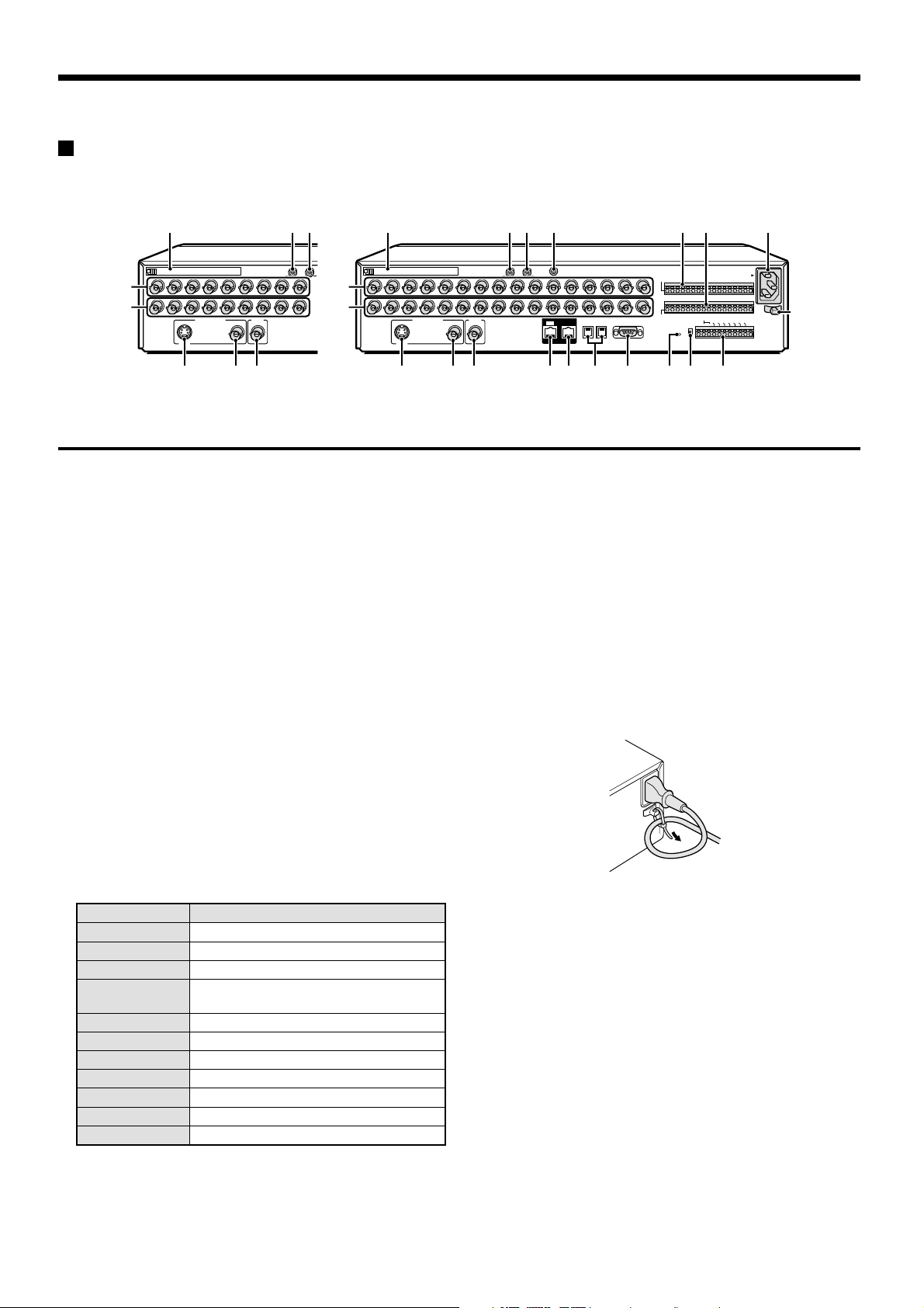
A
Rear panel
DSR-3009P DSR-3016P
213
PC Card SLOT
5
6
1
23456789
MAIN MONITOR MON2
SVHS
AUDIO IN
5
6
987
PC card slot
1
Connect a network card or SCSI card (sold separately) here.
Note: The PC card slot is for 16-bit 5 V cards only.
Do not use 32-bit card bus types of card, as they may
damage the PC card slot of the digital video recorder.
AUDIO IN terminal
2
AUDIO OUT terminal
3
MIC IN terminal
4
VIDEO IN terminal
5
The DSR-3009P model has nine input terminals.
VIDEO OUT terminal
6
The DSR-3009P model has nine output terminals.
MAIN MONITOR S-VIDEO output terminal
7
MAIN MONITOR output terminal
8
MON2 output terminal
9
DIGITAL IN terminal
F
DIGITAL OUT terminal
G
RS485 control terminal
H
RS-232C terminal
I
ALL RESET button
J
RS-485 termination switch
K
Control connector
L
Pin Signal
C Ground
REMOTE R1 Remote control input 1
REMOTE R2 Remote control input 2
CLOCK SET
OUT
ALARM OUT Alarm output
ALARM RESET Alarm reset
NON REC OUT Non REC output
WARNING OUT HDD error warning output
FULL HDD space warning output
ALARM FULL Alarm recording area space warning output
C Ground
Clock setting output (See page 46.)
2134 MN O
1
2345678 1112
MAIN MONITOR
SVHS
PC Card SLOT
MON2
M
N
O
P
109
ALARM IN terminals (1 – 16)
These terminals send alarm signals resulting from the operation of
externally-connected alarm switches to the ALARM OUT control
terminal for output.
The DSR-3009P model has nine alarm input terminals.
SENSOR ALARM OUT terminal (1 – 16)
When a response is received from a motion sensor that has been
set using the menu settings, an alarm signal is output. (open
collector)
The DSR-3009P model has nine alarm output terminals.
AC power socket (AC IN~)
Securely insert the accessory power cord here.
Power cord holder
Secure the power cord to the holder using the accessory cord tie
as shown in the illustration.
AUDIO OUTAUDIO IN
MIC
IN
IN OUT
DIGITAL
15 16
13 14
RS485
B
A
DO NOT CONNECT TO PHONE LINE
RS232C
SENSOR
ALARM OUT
ALARM IN
C1234567891011 12 13 14 15 16
C
W
A
N
L
L
O
A
O
A
A
C
R
N
L
R
K
N
A
R
M
S
I
R
N
E
E
R
M
G
C
REMOTE
T
E
O
O
O
S
RS485
U
U
E
U
T
T
T
T
TERMINATE
CR1R2 C
ON
ALL
RESET
OFF
CONTROL
LKJIHGF987
AC IN~
A
L
A
R
M
F
F
O
U
U
U
L
L
T
L
L
P
P
English
7
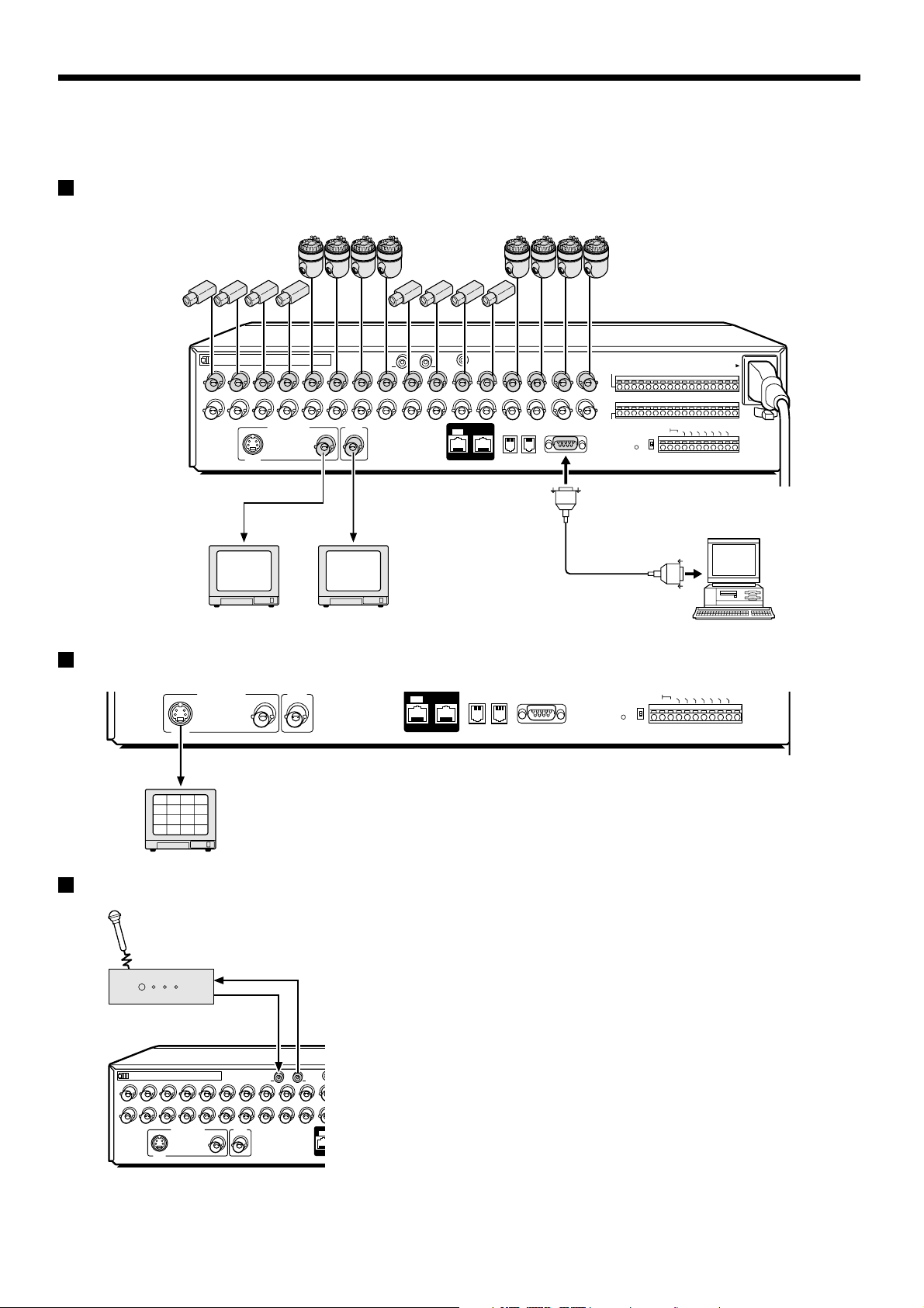
CONNECTIONS
RS485
DIGITAL
Turn off the power for all components before connecting them.
Be sure to carefully read the Instruction Manual for all equipment being connected to the digital video recorder.
If the connections are incorrect, smoke or operating malfunctions may result.
Basic connections (DSR-3016P model)
Nine cameras can be connected to the DSR-3009P model.
2345678 1112
1
MAIN MONITOR
SVHS
S-VIDEO IN
connector
TV monitor
(sold separately)
PC Card SLOT
MON2
VIDEO IN
connector
TV monitor
(sold separately)
MIC
MIC IN
IN
AUDIO OUTAUDIO IN
109
DIGITAL
IN OUT
13 14
DO NOT CONNECT TO PHONE LINE
15 16
RS485
A
B
RS232C
Connecting high image quality (S-VHS) video equipment
MAIN MONITOR
SVHS
S-VIDEO IN connector
2
1
3
4
6
5
7
8
10
9
11
12
14
13
15
16
MON2
IN OUT
B
A
DO NOT CONNECT TO PHONE LINE
RS232C
ALARM OUT
ALARM OUT
ALARM IN
C1234567891011 12 13 14 15 16
SENSOR
RESET
ALL
CLOCK SET OUT
REMOTE
RS485
TERMINATE
CR1R2 C
ON
ALL
RESET
OFF
C
LO
ALARM OUT
C
K
SE
REMOTE
T O
RS485
U
T
TERMINATE
CR1R2 C
ON
OFF
ALARM RESET
NON REC OUT
ALARM OUT
CONTROL
ALARM RESET
NON REC OUT
CONTROL
AC IN~
WARNING OUT
ALARM FULL
FULL
Computer
WARNING OUT
ALARM FULL
FULL
Connecting to an Amplifier
Audio output
Amplifier
(sold separately)
1
2345678 11109
SVHS
MAIN MONITOR
Audio input
PC Card SLOT
MON2
MIC
IN
AUDIO OUTAUDIO IN
IN
8
English
CONNECTIONS
3
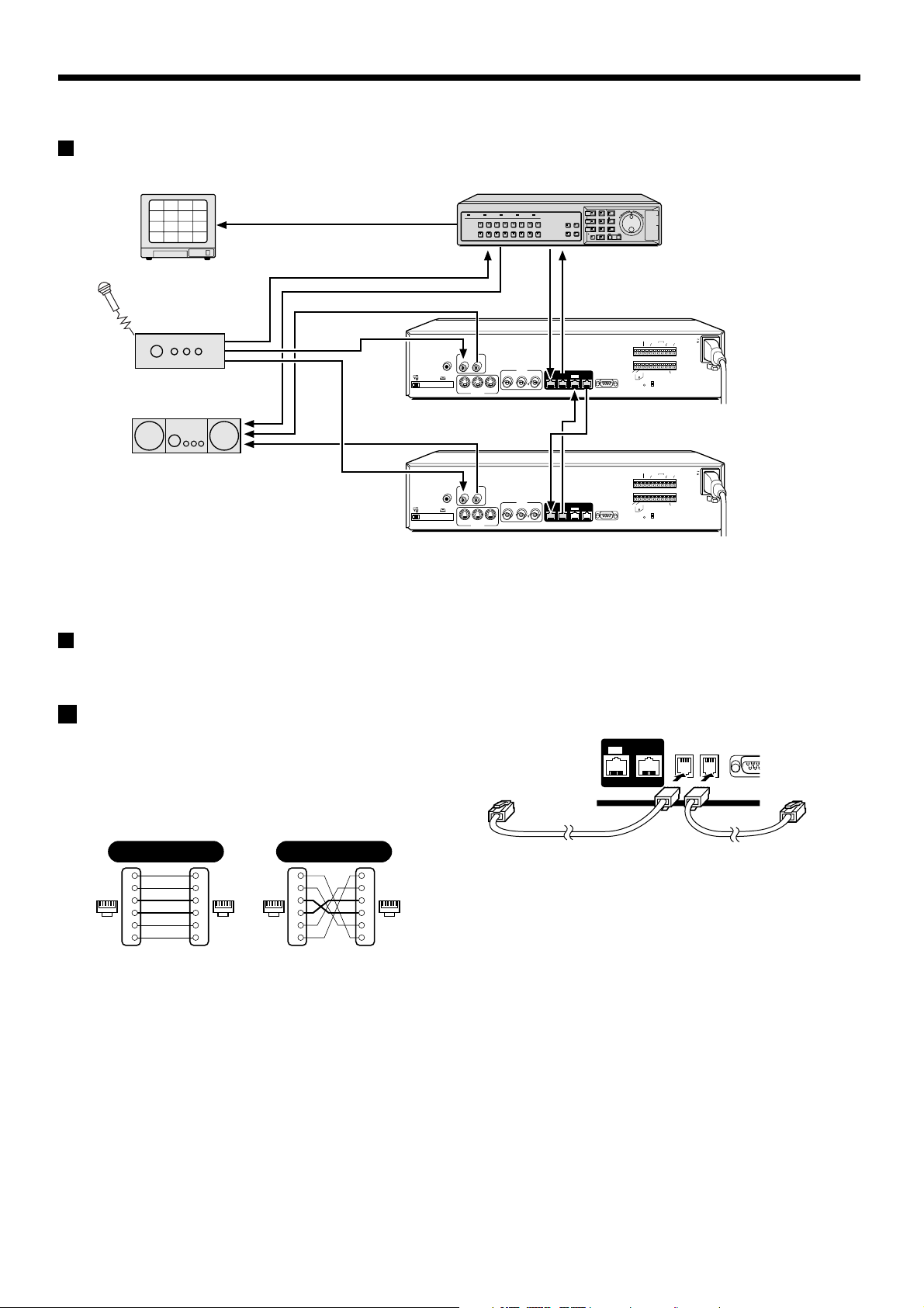
Digital series connections
2
1
3
4
6
5
7
8
10
9
11
12
14
13
15
16
TV monitor
(sold separately)
Amplifier
(sold separately)
Amplifier
(sold separately)
POWER FULL
AUDIO
MIC
IN
OUTIN
EJECT
PC Card SLOT
LOOP OUT
IN
S-VIDEO
(sold separately)
AUDIO
MIC
IN
OUTIN
EJECT
PC Card SLOT
LOOP OUT
IN
S-VIDEO
(sold separately)
ALARM FULL
LOCK ALARM
12345678
910111213141516
VIDEO
LOOP OUT
IN
OUT
OUT
VIDEO
LOOP OUT
IN
OUT
OUT
Digital video recorder (main)
SHUTTLE
PLAY/STOP
MENU
EXIT/OSD
E
N
R
JOG
T
A
E
E
L
R
C
SEARCH
STILL
ZOOM
MULTI
QUAD
SEQUENCE
COPY
SHUTTLE LOCK
PLUS
MON2
ALARM
TIMER
REC/STOP
Digital video recorder (sub 1)
ALARM
CLOCK
AC IN
ADJUST
RESET
OUT
OUT
NON REC
ALARM
WARNING
ALARM
ALARM
FULL
OUT
IN
FULLOUTIN
C
C
NCCC
B
REMOTE
CCNC
SW OUT
DIGITAL
SUB OUT
OUT
SUB IN
IN
AONC
RS232C
RS485
TERMINATE
ALL
RS485
RESET
OFF
Digital video recorder (sub 2)
ALARM
CLOCK
AC IN
ADJUST
RESET
OUT
OUT
NON REC
ALARM
WARNING
ALARM
ALARM
FULL
OUT
IN
FULLOUTIN
C
C
NCCC
REMOTE
CCNC
B
SW OUT
DIGITAL
SUB OUT
OUT
SUB IN
IN
AONC
RS232C
RS485
TERMINATE
ALL
RS485
RESET
OFF
System control connections
Use the RS485 connector to connect a system controller (sold separately) to the digital video recorder. After connecting the system controller, you
will need to carry out the settings that are given in the RS-232C/RS-485 SET menu. (See page 76.)
When using the RS485 (RJ-11) connector
A
Connect modular cables (sold separately) to the RS485 control
connectors at the rear of the digital video recorder.
If using a straight-type cable
••••
Connect connector A to connector A and connector B to connector B.
If using a cross-type cable
••••
Connect connector A to connector B and connector B to connector A.
Straight type Cross type
Spare
1
Spare
2
61616116
3
4
Spare
5
Spare
6
1
2
3
4
5
6
Spare
1
Spare
2
3
4
5
Spare
6
Spare
1
2
3
4
5
6
To other
connector A
Straight-type cable Cross-type cable
DIGITAL
IN OUT
RS485
A B
RS2
DO NOT CONNECT TO PHONE LINE
To other
connector A
English
9
CONNECTIONS
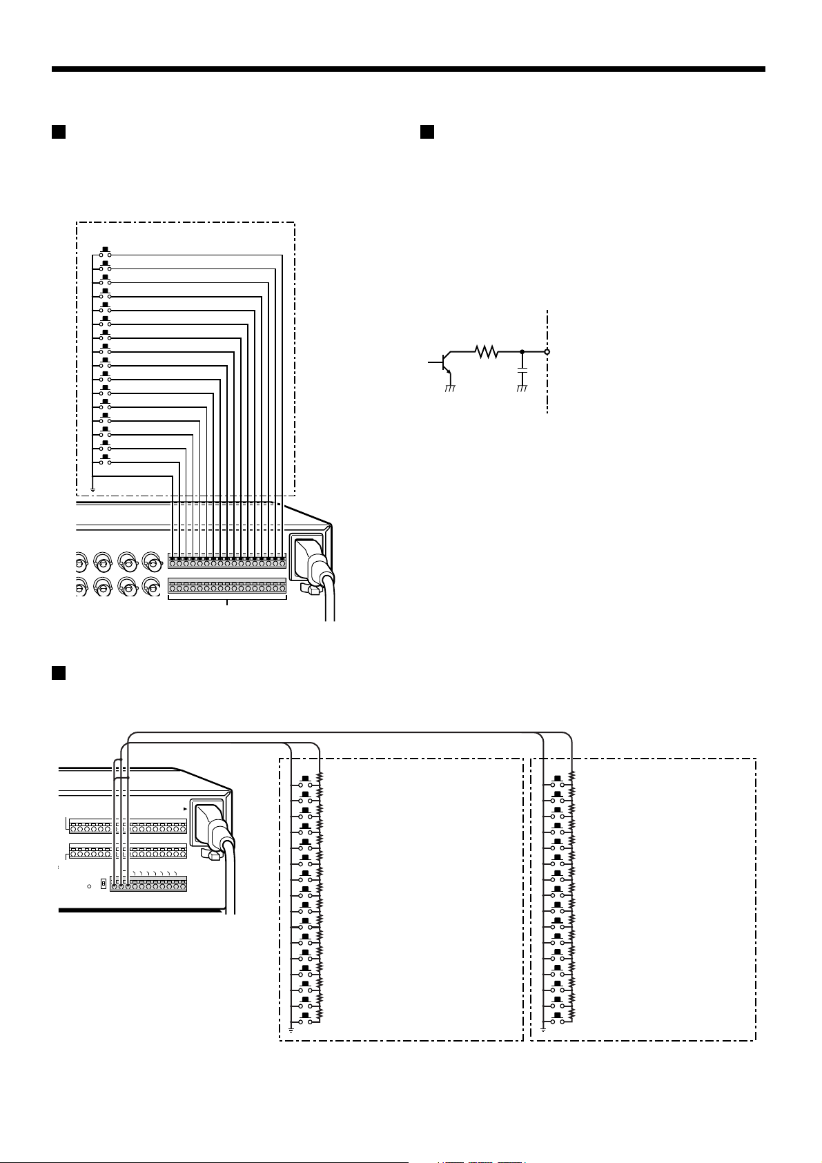
External alarm sensor setup
In order to make an external alarm sensor operate, an external switch
must be connected to an ALARM IN connector. When an intruder
activates the external switch (such as by opening a door), an alarm
signal is received and an alarm can be made to sound.
The DSR-3009P model uses the connectors marked *.
Connect an external switch
to an ALARM IN connector
*
*
*
*
*
*
*
*
*
Using as a monitor board during a
motion sensor alarm
When the motion sensor built into the digital video recorder responds
to an alarm, it outputs an alarm signal to the SENSOR ALARM OUT
connector. If a switching circuit such as a warning lamp is connected
to this connector, the warning lamp will illuminate when there is a
response from the motion sensor. If the warning lamp is fixed
somewhere in the layout diagram for an area such as a factory, the
location of the camera can be ascertained in an instant during an
emergency. The connector is always open. The pin corresponding to
the number of the camera that generates a sensor response switches
to Low.
1K
Rated values for each pin (at 25˚C)
• Max. current
• Max. voltage
• Max. power
25mA
25V
40mW
SENSOR ALARM OUT connector
Connecting a remote control circuit
If a remote control circuit is constructed as shown in the illustration and connected to the remote control input (R1 and R2) terminals of the
CONTROL connector, the digital video recorder can be operated by remote control. (Contact LOW input)
The DSR-3009P model can control up to nine cameras.
R1 R2
A
LA
R
O
U
T
A
N
LA
O
R
M
R
M
E
O
S
U
T
CONTROL
AC IN ~
W
A
A
LA
R
N
N
R
R
IN
E
M
G
C
FU
FU
O
O
U
U
ET
LL
LL
T
T
ALARM IN
C1234567891011 12 13 14 15 16
C
L
O
C
SOR
M OUT
REMOTE
RS485
TERMINATE
CR1R2 C
ON
ALL
RESET
OFF
K
S
E
T
SW: Switch
Note:
The remote control cable should
be no more than 5 m long.
(When used alone)
220Ω
SW 1: Camera1*
220Ω
SW 2: Camera2*
300Ω
SW 3: Camera3*
360Ω
SW 4: Camera4*
470Ω
SW 5: Camera5*
680Ω
SW 6: Camera6*
820Ω
SW 7: Camera7*
1.2kΩ
SW 8: Camera8*
1.8kΩ
SW 9 : Camera9*
2.2kΩ
SW 10 : Camera10
3.3kΩ
SW 11 : Camera11
4.7kΩ
SW 12 : Camera12
7.5kΩ
SW 13 : Camera13
13kΩ
SW 14 : Camera14
27kΩ
SW 15 : Camera15
68kΩ
SW 16 : Camera16
(When R2 SHIFT key
is also pressed)
; Spare
; Spare
; Spare
; Automatic switching display
; Monitor 2
; Plus screen display
; 4-screen display
; Multi-screen display
; Menu reset
; Spare
; Spare
; Spare
; Spare
; Spare
; Spare
; Spare
220Ω
SW 17: Recording stop
220Ω
SW 18: Playback stop
300Ω
SW 19: Pause
360Ω
SW 20: Search
470Ω
SW 21: SHIFT (When R1 and R2 are pressed)
680Ω
SW 22: Playback
820Ω
SW 23: Recording
1.2kΩ
SW 24: Menu
1.8kΩ
SW 25: Menu clear (Exit)
2.2kΩ
SW 26: +
3.3kΩ
SW 27: –
4.7kΩ
3
SW 28:
7.5kΩ
2
SW 29:
13kΩ
SW 30: Zoom
27k
SW 31: Copy
68kΩ
SW 32: Timer recording
10
English
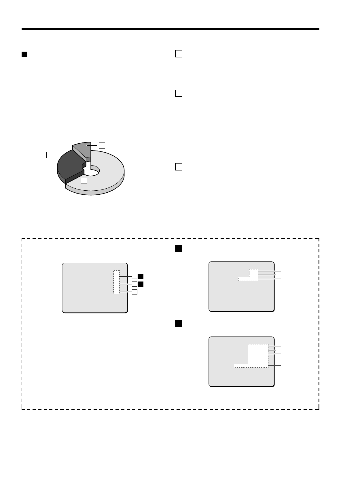
BUILT-IN HARD DISK
1%
80%
19%
Hard disk
Recording areas
The recording areas on the hard disk (normal recording area: 80%,
alarm recording area: 19%, archive area: 1%) are established
automatically when the power for the digital video recorder is turned
on. Images are recorded in the normal recording area when the
REC/STOP button is pressed, and they are recorded in the alarm
recording area when an alarm occurs. This is called the default
condition, and the following detailed settings can be confirmed in the
sections on “RECORDING IMAGES IN THE NORMAL RECORDING
AREA” and “RECORDING IMAGES IN THE ALARM RECORDING
AREA” (See page 22.) which are explained later. Furthermore,
settings such as the recording areas and picture quality can be
changed using the menu screens.
Archive areaC
80%
80%
Alarm
B
Alarm
recording
recording
area
area
1%
1%
19%
19%
Normal recording areaNormal recording areaA
Hard disk recording areas
A Normal recording area
When the REC/STOP button is pressed while monitoring is in
••••
progress, images are recorded in the normal recording area.
When start and end times are entered for each day of the week
••••
and are then enabled, timer recording is automatically carried out
in the normal recording area between the times that have been set.
B Alarm recording area
ALARM REC MODE SET menu settings are required.
Alarm recording is enabled when ALARM RECORDING is set.
••••
When a suspicious person is detected by the switch or motion
sensor that is connected to the alarm input terminal, an alarm is
recorded in the alarm recording area.
Pre-alarm recording is enabled when PRE-ALARM RECORDING
••••
is set. Pre-alarm recording repeatedly records the same images as
for normal recording in the alarm recording area, and overwrites
these images after the set time interval, until an alarm is detected.
When pre-alarm recording is set, the image immediately before an
alarm occurred can be recorded.
C Archive area
This is the area for copying important images from the normal
recording area and the alarm recording area. The size of the archive
area can be set to a maximum of 10 GB (12.5% of total capacity when
using an 80-GB hard disk 6% of total capacity when using an 160-GB
hard disk) by changing the size of the normal recording area or the
alarm recording area.
Menu screen (initial setting)
This can be displayed by pressing the MENU button.
<RECORDING AREA SET>
TOTAL CAPACITY : 80GB
NORMAL RECORDING AREA : 80 %
AREA FULL RESET ->
ALARM RECORDING AREA : 19 %
AREA FULL RESET ->
ARCHIVE AREA : 1 %
AREA FULL RESET ->
CAUTION : WHEN THE AREA SETTING IS CHANGED,
THE WHOLE AREA WILL BE INITIALIZED !
1
PICTURE QUALITY: NORMAL
Picture quality can be selected from five options.
The recording speed changes in accordance with the picture
quality selected.
2
AUDIO RECORDING: Can be set to ON or OFF.
3
REC RATE: Shows the recording interval and the
recording time.
Refer to the recording speed table for further details.
4
ALARM RECORDING: Can be set to ON or OFF.
When alarm recordings are to be made, select a setting such
as ENABLED for the OFF setting. The recording speed and
alarm duration will be displayed
ABA
B
C
A
Setting screen for normal recording area picture quality,
recording speed, etc.
<NORMAL REC MODE SET>
PICTURE QUALITY : NORMAL
AUDIO RECORDING : ON
REC RATE : 8.33FPS ( 57H)
REC PROGRAM GROUP : OFF
B
Setting screen for alarm recording area picture quality,
recording speed, etc.
<ALARM REC MODE SET>
PICTURE QUALITY : SUPER FINE
AUDIO RECORDING : ON
ALARM RECORDING : ENABLED
ALARM INTERLEAVE : ONLY
PROGRAM GROUP : OFF
REC RATE :@ 0.1FPS, DURATION: 40SEC
PRE-ALARM RECORDING : ON
REC RATE :@ **** FPS, DURATION: ***
=> (01010 ALARMS CAN BE RECORDED )
ALARM TRIGGER : ALARM
2
2
1
3
1
4
3
English
11
BUILT-IN HARD DISK
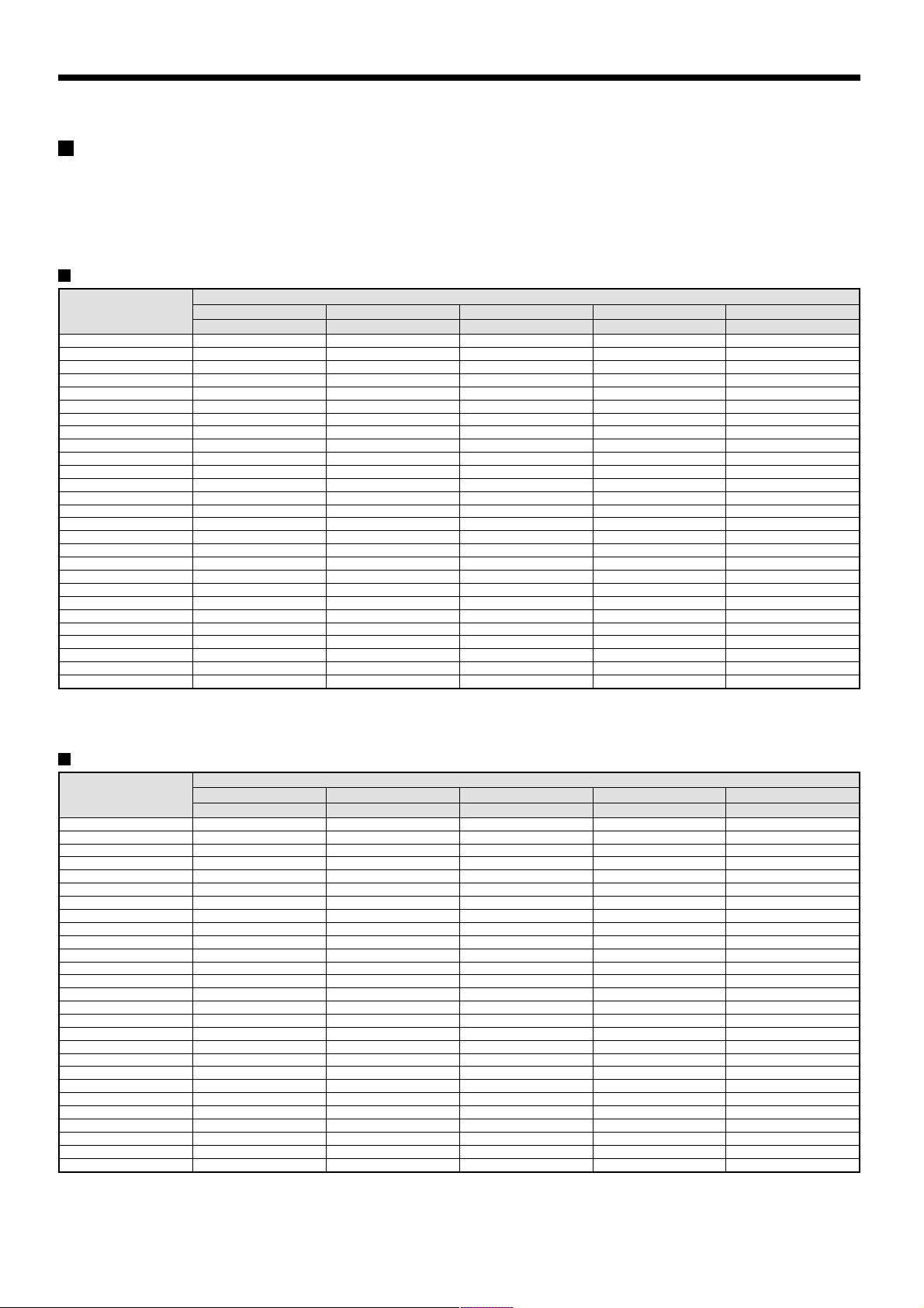
Recording speed tables (The recording time may vary depending on the images being
recorded.)
These recording speed tables show the recording times for various picture quality and frame/field settings when recording in the normal recording
area of the hard disk (80 GB). They do not include audio recording settings.
The recording times for the normal recording area and the alarm recording area represent the recording time values given in the recording speed
tables, multiplied by the percentages for the normal recording area and alarm recording area that have been set using the recording area setting menu
commands.
When recording with an 80-GB hard disk at 100% capacity
Recording Rate
(field/sec)
BASIC NORMAL ENHANCED FINE SUPER FINE
15 kB 22 kB 30 kB 42 kB 56 kB
50.00 25H 18H 13H 9H 7H
25.00 51H 36H 27H 19H 14H
16.67 76H 54H 40H 29H 22H
12.50 102H 72H 54H 39H 29H
8.33 153H 108H 81H 59H 44H
6.25 204H 144H 108H 78H 59H
5.00 255H 180H 135H 98H 74H
4.17 306H 217H 162H 118H 89H
3.57 357H 253H 189H 138H 104H
3.13 408H 289H 217H 157H 119H
2.78 459H 325H 244H 177H 134H
2.50 510H 361H 271H 197H 149H
2.27 561H 397H 298H 217H 164H
1.92 663H 470H 352H 256H 194H
1.67 765H 542H 406H 295H 224H
1.47 868H 614H 461H 335H 254H
1.32 970H 687H 515H 374H 284H
1.19 1072H 759H 569H 414H 314H
1.09 1174H 831H 623H 453H 344H
1.00 1276H 904H 678H 493H 374H
0.50 2553H 1808H 1356H 986H 748H
0.33 3829H 2712H 2034H 1479H 1122H
0.25 5106H 3616H 2712H 1972H 1496H
0.20 6382H 4521H 3390H 2466H 1870H
0.10 12765H 9042H 6781H 4932H 3741H
0.05 25531H 18084H 13563H 9864H 7483H
0.03 38296H 27126H 20345H 14796H 11224H
The tables below are recording time tables provided for reference if the total capacity of the hard disk has been increased to 160 GB. (Contact the
place of purchase for details on increasing the capacity of the hard disk.)
RECORDING TIME
When recording with a 160-GB hard disk at 100% capacity
Recording Rate
(field/sec)
50.00 51H 36H 27H 19H 14H
25.00 102H 72H 54H 39H 29H
16.67 153H 108H 81H 59H 44H
12.50 204H 144H 108H 78H 59H
8.33 306H 217H 162H 118H 89H
6.25 408H 289H 217H 157H 119H
5.00 510H 361H 271H 197H 149H
4.17 612H 434H 325H 236H 179H
3.57 714H 506H 379H 276H 209H
3.13 816H 578H 434H 315H 239H
2.78 919H 651H 488H 355H 269H
2.50 1021H 723H 542H 394H 299H
2.27 1123H 795H 596H 434H 329H
1.92 1327H 940H 705H 512H 389H
1.67 1531H 1085H 813H 591H 448H
1.47 1736H 1229H 922H 670H 508H
1.32 1940H 1374H 1030H 749H 568H
1.19 2144H 1519H 1139H 828H 628H
1.09 2348H 1663H 1247H 907H 688H
1.00 2553H 1808H 1356H 986H 748H
0.50 5106H 3616H 2712H 1972H 1496H
0.33 7659H 5425H 4069H 2959H 2244H
0.25 10212H 7233H 5425H 3945H 2993H
0.20 12765H 9042H 6781H 4932H 3741H
0.10 25531H 18084H 13563H 9864H 7483H
0.05 51062H 36168H 27126H 19728H 14966H
0.03 76593H 54253H 40690H 29592H 22449H
Reference: 24H = 1 day, 168H = 1 week, 720H = 1 month, 8760H = 1 year
BASIC NORMAL ENHANCED FINE SUPER FINE
15 kB 22 kB 30 kB 42 kB 56 kB
RECORDING TIME
12
English
BUILT-IN HARD DISK
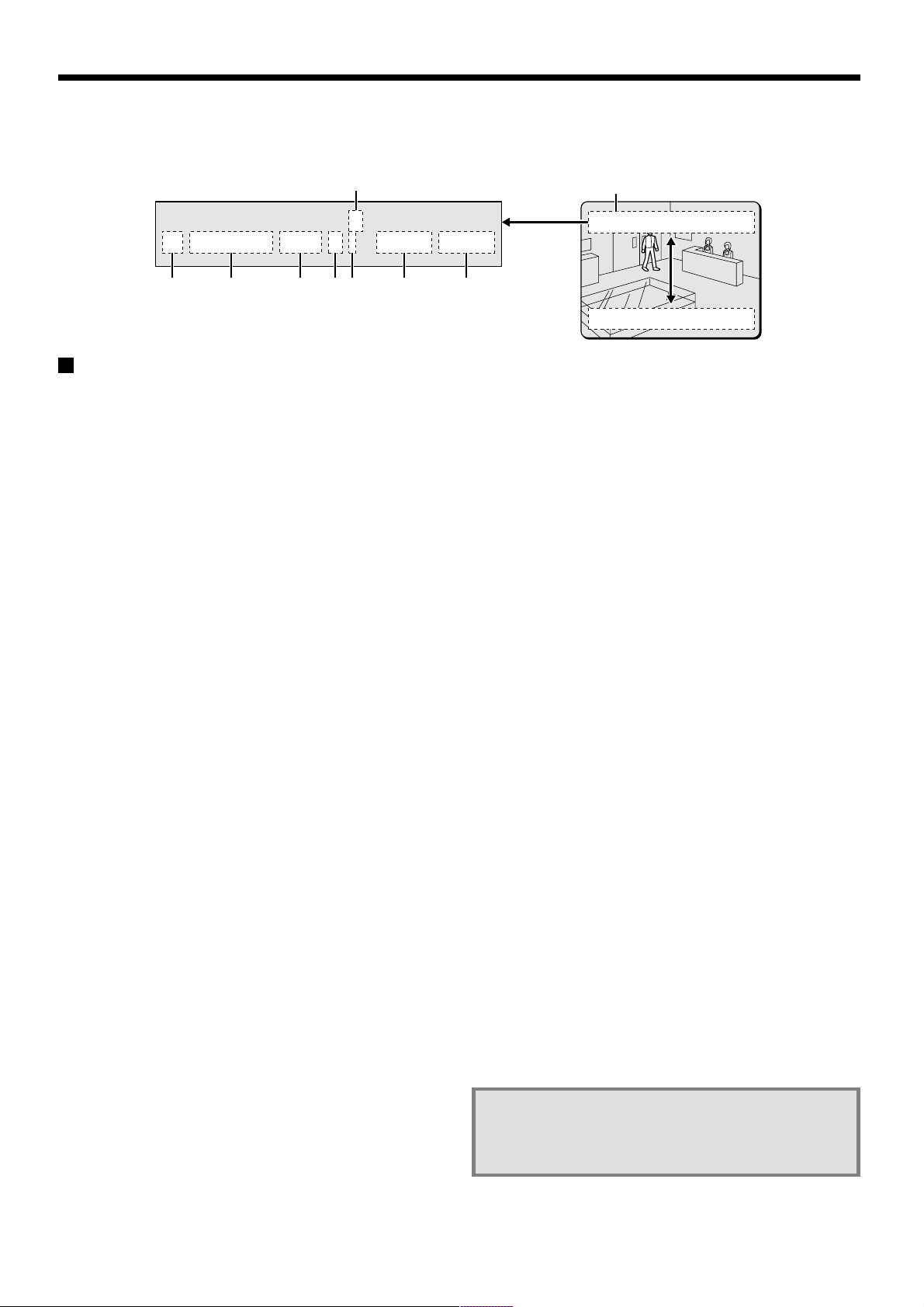
When the power for the digital video recorder is turned on, the operating display appears at the top of the monitor screen. This operating display
shows information which is essential for operation, such as the date, time and picture quality.
1
02
REC ALARM 0000 REPEAT EN A 01-01-02 00:00:00
2
Operating display
☞ Insert the power cord into a wall outlet and turn
on the power.
The POWER indicator illuminates, and after approximately 15
seconds the EXIT/OSD indicator illuminates. The camera images then
appear on the monitor screen and the operating display appears at
the top of the screen.
Note: If you press the EXIT/OSD button repeatedly, you can change
the display position for the operating display or make it
disappear.
Camera number display
1
This displays the number of the camera that is currently being
played back or monitored.
Operating symbol display
2
These symbols appear during recording and playback.
REC : Recording e : Fast forward
c : Playback f : Rewind
d : Reverse playback hc : Slow playback
h : Stopped dh : Slow reverse playback
Note: If recording and playback are being carried out at the same
time, the playback symbol (c) appears.
Alarm display and alarm number display
3
When an alarm setting is made using the ALARM REC MODE
SET menu item, The following display appears in the alarm display.
However, the PRE display appears when pre-alarm recording has
been set. When an alarm occurs, the PRE is replaced by ALARM
and the number of alarms also appears. The alarm display shows
the cumulative number of alarms.
•
If ALARM REC MODE SET is set: “ALARM” appears.
The “ALARM” display flashes during alarm recording.
•
If PRE ALARM RECORDING is set: “PRE” appears.
•
When playing images from the archive area: ARCHIVE
appears.
•
When an external alarm is received: “EA” flashes to the left of
the camera number.
•
When a motion sensor alarm is received: “SA” flashes to the
left of the camera number.
3 4 5 6 7 8
Operating display
02
REC ALARM 0000 REPEAT EN A 01-01-02 00:00:00
REC ALARM 0000 REPEAT EN A 01-01-02 00:00:00
02
Amount of recording area remaining
4
“REPEAT” appears when overwriting is enabled. Furthermore, if
overwriting has been disabled (OVERWRITE: OFF) for the normal
recording area and the alarm recording area, the amount of space
remaining appears as a percentage.
You can change the amount of recording area remaining using the
RECORDING AREA SET menu item. (See page 51.)
Picture quality display
5
This shows the picture quality for images that are recorded on the
hard disk. The default setting is EN (Enhanced). The display
changes when the picture quality is changed using the NORMAL
REC MODE SET menu item.
•
BA: Basic
•
NO: Normal
•
EN: Enhanced
•
FI: Fine
•
SF: Super Fine
Audio recording display
6
“A” appears when audio recording is enabled. See page 54 for
details on the audio recording settings.
Date display
7
When the digital video recorder is first turned on, the date appears
as 01-01-02 (day, month, year). Make sure that you use the
menus to set the correct date.
Time display
8
When the digital video recorder is first turned on, the time appears
as 00:00:00, and the time starts counting after the date has been
set. The digital video recorder uses the date and time to control
recording and playback, so if the date and time have not been set,
the correct images cannot be retrieved. Make sure that you use
the menus to set the correct time. If this is not set, recording will
not be possible.
English
Note: During recording with this unit, playing back,
copying and transferring pictures is possible.
However, because of the recording priority the
response of the other operations becomes slower.
13
VIEWING CAMERA IMAGES
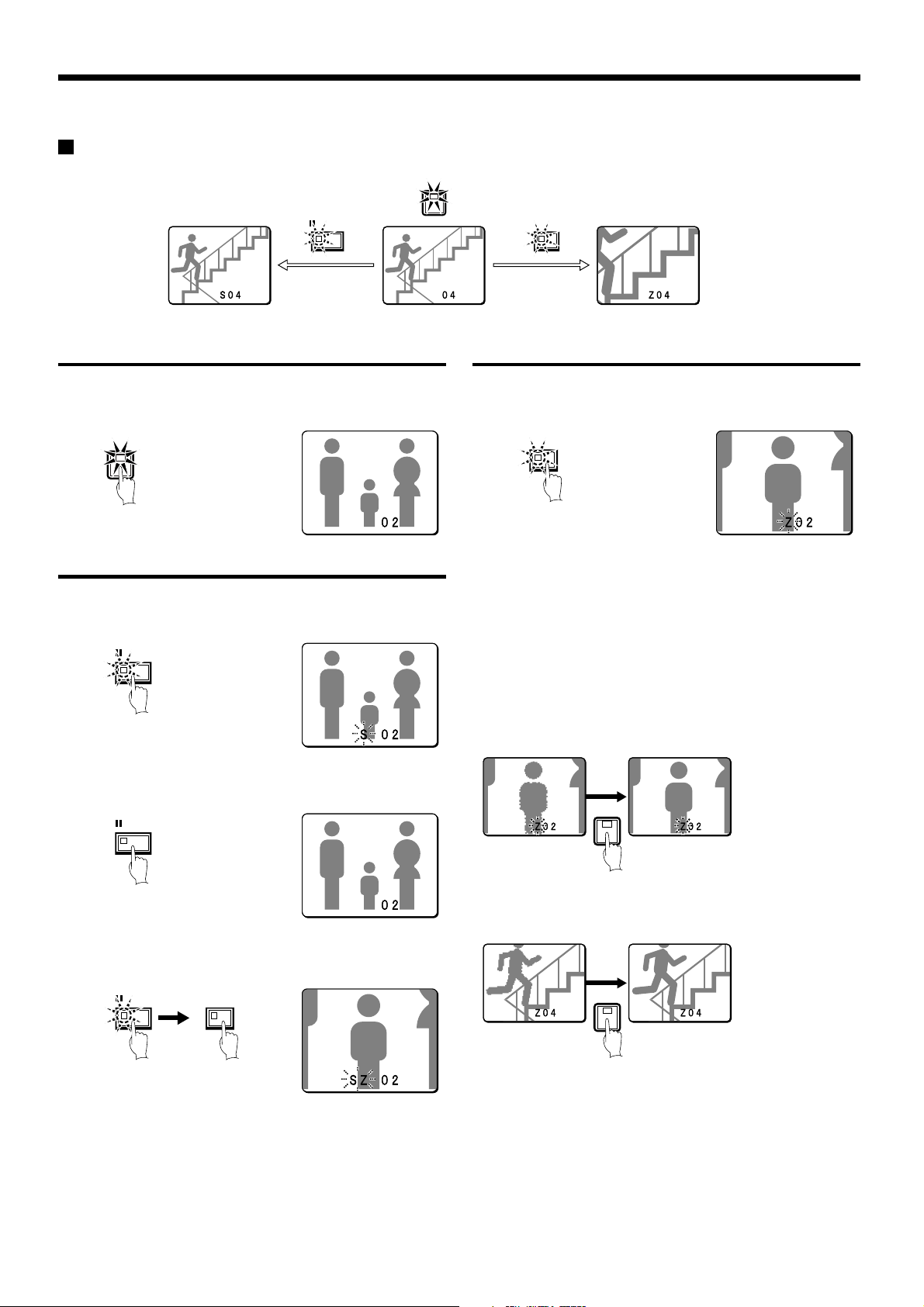
Viewing a single-screen image
4
ZOOMSTILL
Still image
Single-screen
Setting the camera image to single-screen display
1
Press a camera select button (example: 2).
The camera 2 image appears as a single-screen.
2
Pausing images
1
Press the STILL button.
The image will be paused.
STILL
Zoom
Enlarging images
1
Press the ZOOM button.
The images will be enlarged.
ZOOM
Note: If you set a zoom frame, the area of the image inside the zoom
frame will be enlarged. (See page 15.)
If you press the camera select button while
zooming, the image will be easier to see due to the
movement of the subject. The following changes
will occur if you press the camera select button
repeatedly.
An image with little movement (almost a still image)
•
Large subjects become clearer and moving subjects appear a little
rough.
2
To cancel the still image, press the STILL button once more.
Pausing will be canceled and normal images will appear.
STILL
Note: If you press the ZOOM button while the image is paused, the
still image will be enlarged. To return to the original still image,
press the ZOOM button once more.
STILL
ZOOM
2
Enlarged image is a
little rough
An image with large movement (normal viewing)
•
The image of a moving subject becomes clearer and subjects with
little movement appear a little rough.
Subject becomes
clearer
4
Enlarged image is a
little rough
Note: If you press some other camera select button while zooming is
in progress, the zooming will be canceled and the display will
change to a single-screen image for the selected button.
Subject becomes
clearer
14
English
VIEWING CAMERA IMAGES
2
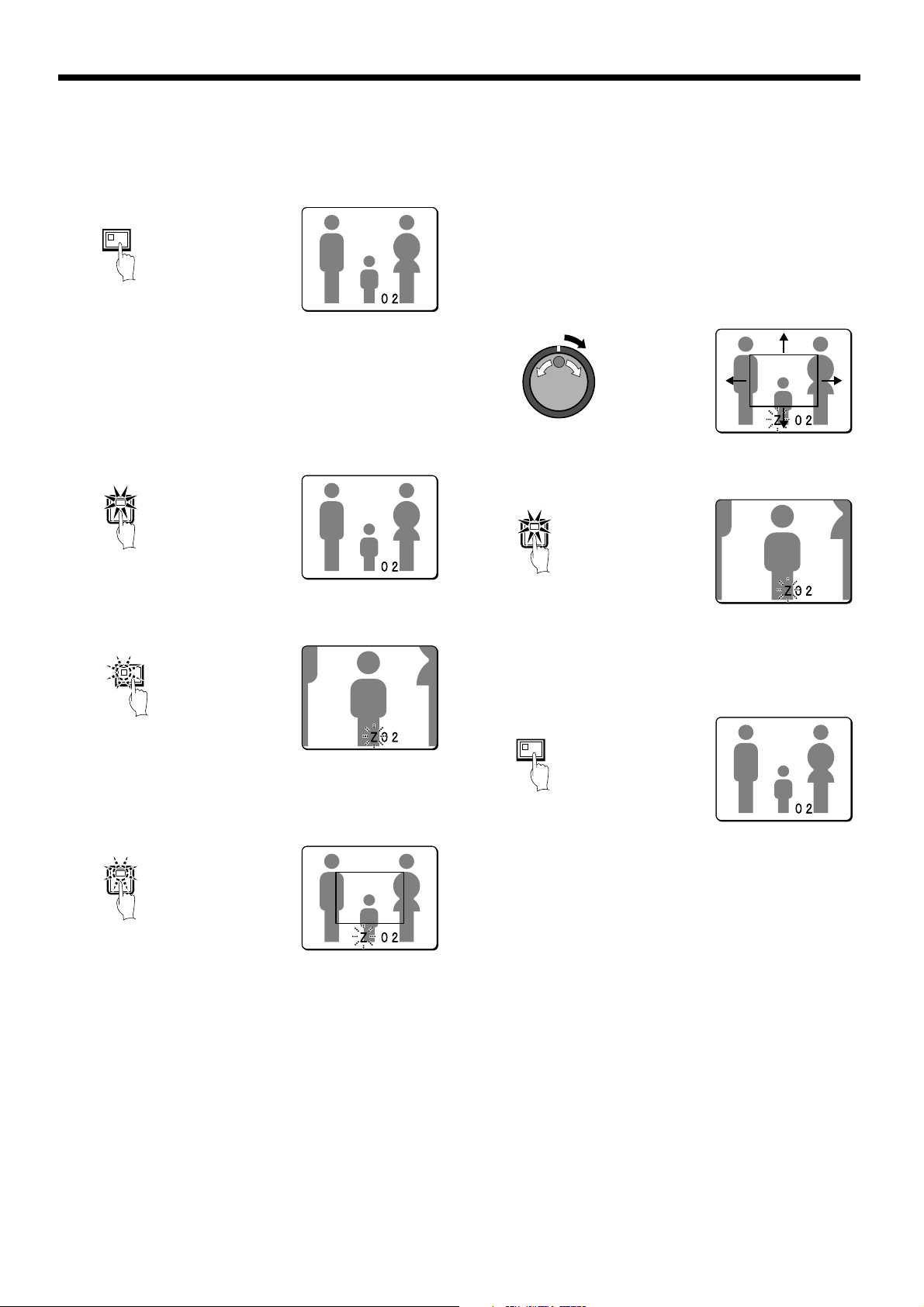
To return an enlarged image to normal image display, press
the ZOOM button once more.
The zoom will be canceled and normal images will appear.
ZOOM
Example: To zoom in on the camera 2 image and
move the zoom frame
You can select the zoom position by means of the zoom frame which
appears on the screen. The zoom frame is set initially at the middle of
the screen.
1
Press camera select button 2.
The camera 2 image will appear in a single-screen display.
2
4
Move the zoom frame to the section of the image to be
enlarged.
•
If you turn the jog dial clockwise, the zoom frame will move to
the right. If you turn it counterclockwise, the zoom frame will
move to the left.
•
If you turn the shuttle dial clockwise, the movement direction
changes to vertical movement. If you then turn the jog dial
clockwise, the zoom frame will move down, and if you turn it
counterclockwise, the zoom frame will move up.
Move the zoom frame to the section of the image to be
enlarged.
5
Press camera select button 2 once more.
The image in the repositioned zoom frame will be enlarged.
2
2
Press the ZOOM button.
The images will be enlarged.
ZOOM
3
Press and hold camera select button 2 for about 3 seconds or
more.
The zoom will be canceled and the normal image will appear, and
the zoom frame (G) will appear on the screen.
2
Note: If the zoom frame remains on the screen for about 10 seconds
without being adjusted, the screen will return to zoom display.
To make the zoom frame reappear, press and hold camera
select button 2 again for 3 seconds or more.
Note: If you press the STILL button while the images are being
zoomed, an enlarged still image will be displayed.
6
To return an enlarged image to normal image display, press
the ZOOM button once more.
The zoom will be canceled and normal images will appear.
ZOOM
English
15
VIEWING CAMERA IMAGES
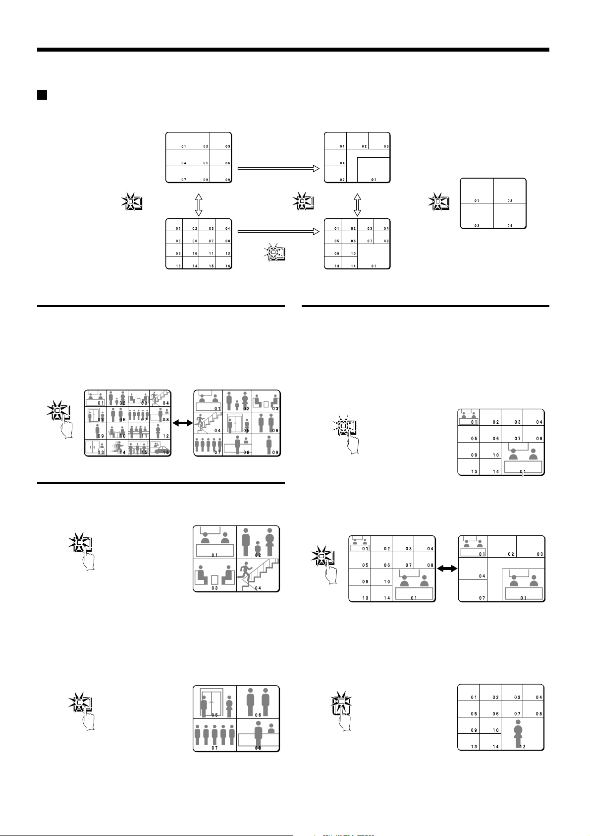
Viewing multiple-screen images
Images from the cameras that are connected to the digital video recorder can be displayed in several split-screen formats. Furthermore, the
images from each camera can be displayed in any position within the split screen. (See page 81.)
MULTI
9-screen display
16-screen display
Viewing images as 9-screen or 16-screen displays
1
Press the MULTI button.
The display switches between 9-screen and 16-screen displays
each time the MULTI button is pressed.
To return to a single-screen display, press a camera select button.
For the DSR-3009P model, only the 9-screen display is available
with no switching.
MULT
Viewing images as a 4-screen display
PLUS
MULTI
6-screen display
13-screen display
QUAD
4-screen display
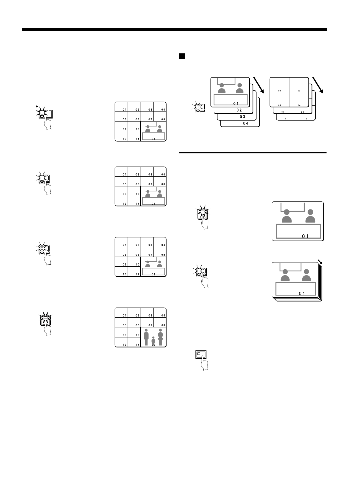
Plus screen viewing
The plus screen allows you to display the images from each camera
as a quarter-screen display in the lower right corner of the split-screen
display. In addition, images being recorded can be played back in the
same position.
1
Press the PLUS button.
The display changes to show a 13-screen display with a plus
screen as a quarter-screen picture in the lower-right corner.
For the DSR-3009P model, a 6-screen display appears.
PLUS
Plus screen
1
Press the QUAD button.
Images appear as a 4-screen display.
QUAD
2
Press the QUAD button once more.
Camera images are switched in 4-screen display units (1 – 4, 5 – 8,
9 – 12, 13 – 16) each time the button is pressed.
To return to a single-screen display, press a camera select button.
For the DSR-3009P model, a 4-screen display of images from
cameras 1 – 4, 5 – 8, or 9 – 3 will appear each time the button is
pressed.
QUAD
2
Press the MULTI button.
The display switches between 13-screen and 6-screen each time
the MULTI button is pressed.
MULT
3
Press a camera select button (example: 12).
The images from the selected camera will be displayed in the plus
screen. To cancel the plus screen, press the PLUS button once
more.
For the DSR-3009P model, press a camera select button
numbered 9 or less.
12
16
English
VIEWING CAMERA IMAGES
Example: To display images from camera 2 in the
plus screen
Record the images on the hard disk beforehand. (See page 20.)
1
Press the PLAY/STOP button.
All screens will start playing back.
PLAY/STOP
2
Press the PLUS button.
The plus screen is displayed.
PLUS
3
Press the PLUS button once more.
The plus screen continues to show the playback images, and the
other split-screen displays show images in monitoring mode.
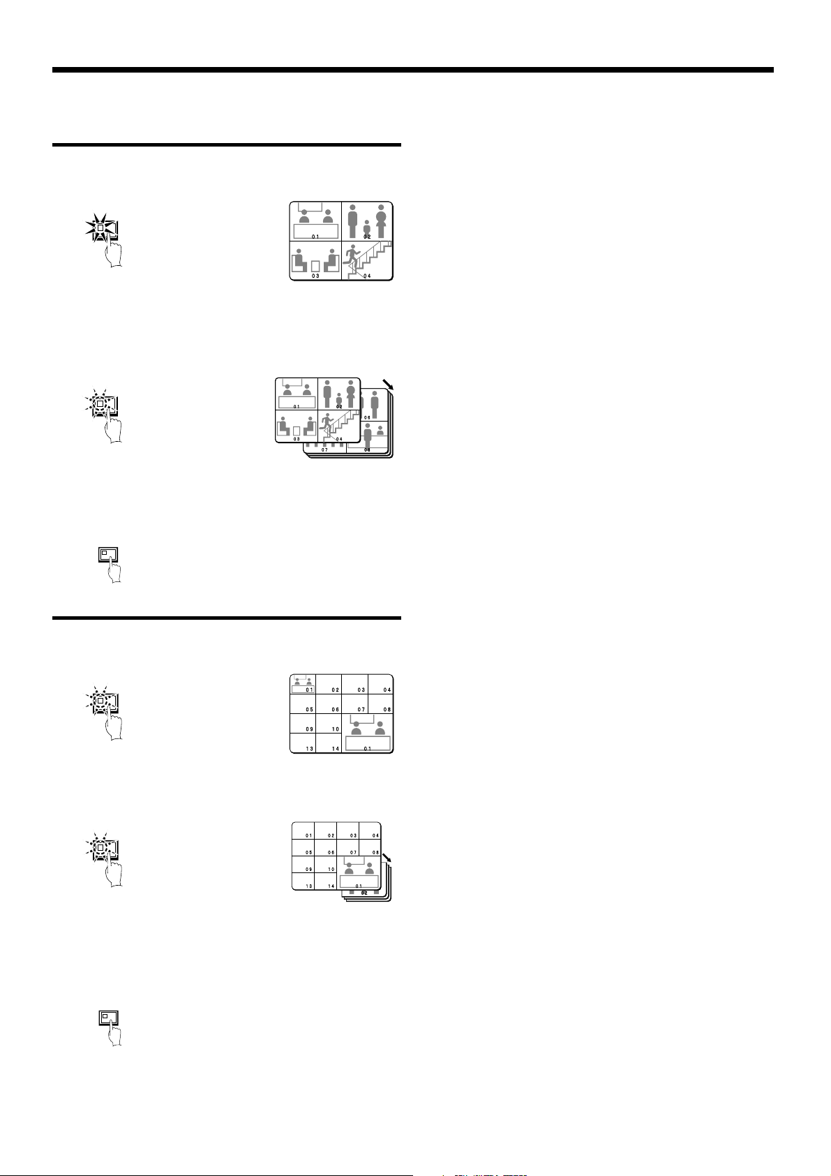
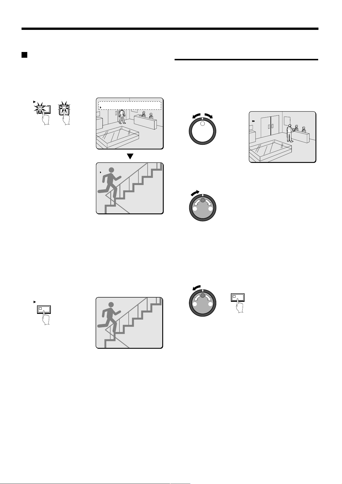
Viewing automatically switching images
The camera images are switched automatically in the order that has
been set using the SEQUENCE settings. (See page 82.)
SEQUENCE
Automatic switching of
Automatic switching of
single-screen display
Automatically switching of the single-screen images
1
Switch to single-screen display, and then press the camera
select buttons to select the camera for automatic switching
(example: 1).
The camera select buttons for the cameras that were selected are
stored in memory.
The indicator will illuminate when the next button is pressed.
1
4-screen display
PLUS
4
Press camera select button 2.
The plus screen changes to show the images being recorded by
camera 2.
2
Note:
See page 20, 24 for further details on recording and playback.
•
To stop playback, press the PLAY/STOP button once more. The
•
display returns to the plus screen.
2
Press the SEQUENCE button.
SEQUENCE
3
To cancel automatic switching, press the SEQUENCE button
once more, or press one of the individual camera select
buttons.
Automatic switching will be canceled and normal images will
appear.
SEQUENCE
English
17
VIEWING CAMERA IMAGES
Automatically switching of the 4-screen images
1
Press the QUAD button.
Images appear as a 4-screen display.
QUAD
2
Press the SEQUENCE button.
Camera images will be switched automatically in 4-screen display
units (1 – 4, 5 – 8, 9 – 12, 13 – 16).
For the DSR-3009P model, images from cameras 1 – 4, 5 – 8, or
9 – 3 will be switched automatically.
SEQUENCE
3
Press the SEQUENCE button once more to return to the
4-screen display.
Automatic switching will be canceled and 4-screen display will be
restored.
SEQUENCE
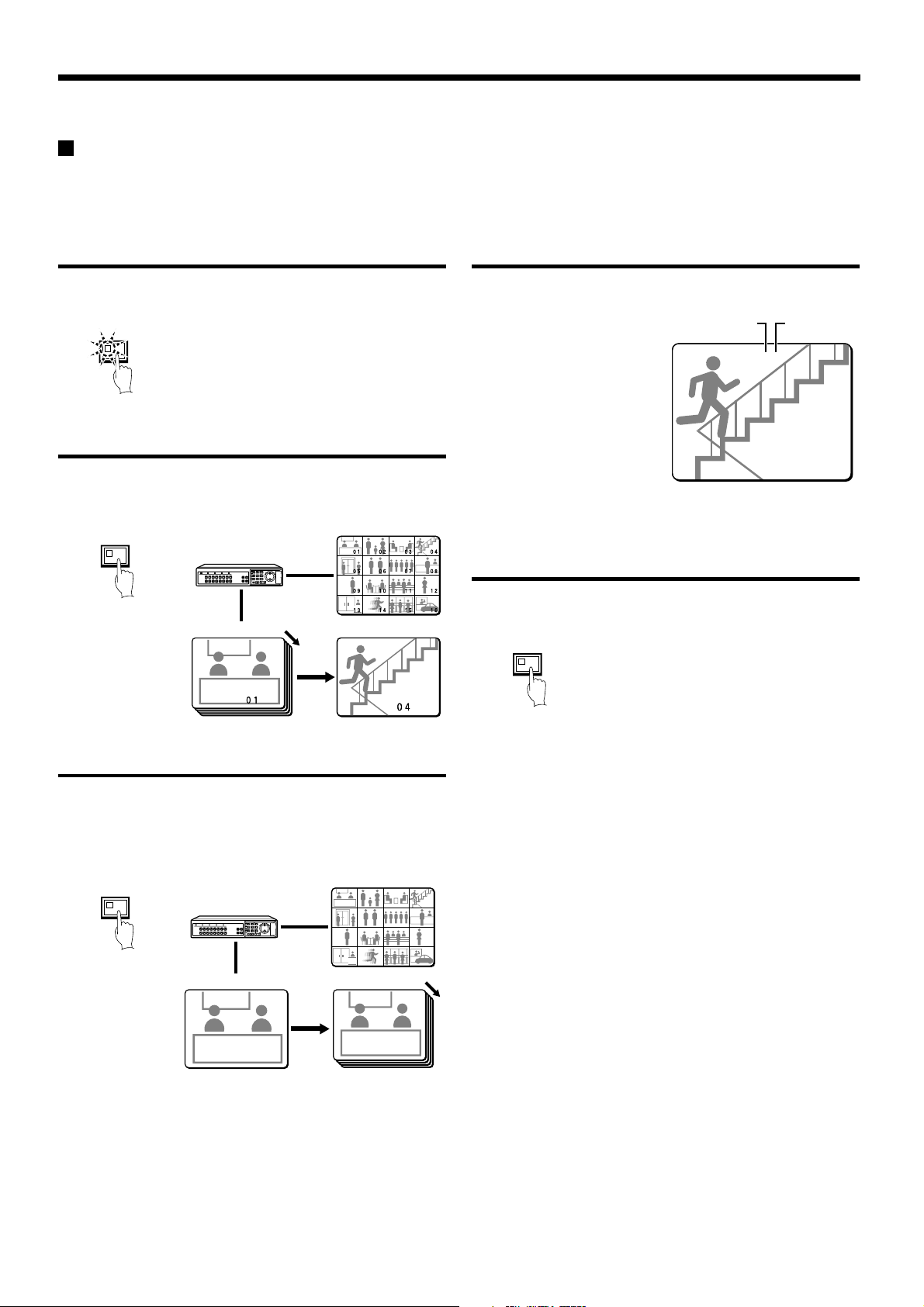
Automatically switching of the plus screen image
1
Press the PLUS button.
The plus screen is displayed.
PLUS
2
Press the SEQUENCE button.
The camera images in the plus screen will be switched
automatically.
SEQUENCE
3
Press the SEQUENCE button once more to return to the plus
screen.
Automatic switching will be canceled and the plus screen will
appear.
To cancel the plus screen, press the PLUS button once more.
SEQUENCE
18
English
VIEWING CAMERA IMAGES
05
09
13
EA 04
EN 16-06-02 11:18:13
Using two monitors for monitoring
If you connect a monitor to the MON2 output terminal on the rear panel, you can display the images from each camera as single-screen images or
show an automatic switching screen on monitor 2, even while the main monitor is showing a split-screen display. In addition, the camera images
can be shown in a single-screen display during playback, and when an alarm occurs, the alarm camera images can be automatically sent to
monitor 2. The default setting is automatic switching of a single screen.
Operating monitor 2
Press the MON2 button.
The MON2 indicator flashes.
MON2
Displaying single-screen camera 4 images on
monitor 2
Press camera select button 4.
The images from camera 4 appear on monitor 2 in a single-screen
display.
SEQUENCE
12345678
910111213141516
Monitor 2
SHUTTLE
R
JOG
A
E
L
C
Main monitor
Monitor 2
Displaying single-screen alarm images on monitor 2
When an alarm is received, the alarm images will be displayed on
monitor 2 as single-screen images.
External
alarm
EA 04
EA 04
EN 16-06-02 11:18:13
EN 16-06-02 11:18:13
Camera
number
Note: If alarm images are being displayed on monitor 2, change the
“MON.2 DISPLAY” setting in the (ALARM OPERATION SET)
menu to “ON”. (See page 66.)
Canceling monitor 2 display
Press the MON2 button once more.
The MON2 indicator switches off.
MON2
Changing monitor 2 from single-screen display to
automatic switching
Press the SEQUENCE button.
The camera images being displayed on monitor 2 will switch
automatically.
To cancel automatic switching, press the SEQUENCE button once
more.
SEQUENCE
12345678
910111213141516
Monitor 2
SHUTTLE
R
JOG
A
E
L
C
010101
Main monitor
01 02 03 04
0101 0202 0303 0404
05 06 07 08
0606 0707 0808
05
09 10 11 12
1010 1111 1212
09
1414 1515 1616
13
13 14 15 16
Monitor 2
010101
English
19
RECORDING IMAGES IN THE
NORMAL RECORDING AREA
Normal recording
Images can be recorded in the normal recording area while they are being monitored.
If the time has not been set, the digital video recorder cannot make recordings. Be sure to set the time. (See page 44.)
Monitored images
are recorded.
1
Setting the time
Press the MENU button to display the LANGUAGE/CLOCK SET
menu, and set the date and time. After the setting has been made,
press the EXIT/OSD button, the date and time appear in the
operating display. (See page 44.)
MENU
Note: If the “PROGRAM REC SET” setting is set in the menu screen,
program recording of the images for each camera will be
possible. (See page 55.)
2
Press the REC/STOP button.
“REC” appears in the operating display and the images being
monitored are recorded in the normal recording area. Recording onto
the hard disk proceeds automatically (default setting) according to the
following settings. The settings can be changed between long-period
recording and high-quality recording in five steps. (See page 55.)
Hard disk recording areas:
•
Normal recording area: 80%
Alarm recording area: 19%
Archive area: 1%
Picture quality: EN (Enhanced)
•
Recording speed: 8.33 FPS (81H)
•
<LANGUAGE/LANGUE/SPRACHE/IDIOMA>
ENGLISH
<CLOCK SET>
01-01-2002 TUE 00:00:00
<SUMMER TIME SET>
MODE : USE
WEEK MONTH TIME
ON LST-SUN 03 02:00
OFF LST-SUN 10 02:00
<EXT.CLOCK SET>
ADJUST.TIME 01:00
3
Press and hold the REC/STOP button for 3 seconds or more.
The “REC” in the operating display disappears and recording stops.
REC/STOP
Green → Red
REC/STOP
Note: Playback is possible during recording. When the PLAY/STOP
button is pressed during recording, “c” appears in the
operating display and images are played back from the point
where recording began.
01
REC REPEAT EN 27-10-02 10:48:38
01
EN 26-10-02 11:02:28
Recording start time
20
English
RECORDING IMAGES IN THE NORMAL RECORDING AREA
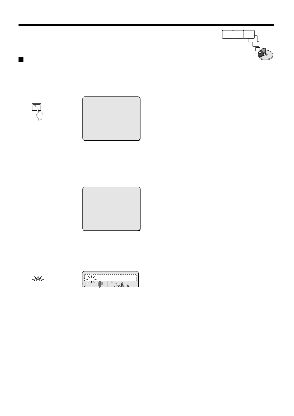
Timer recording
The monitored images can be recorded automatically by setting start and end times for each day of the week.
1
Setting the time
1
Press the MENU button to display the LANGUAGE/CLOCK SET
menu, and set the date and time. After the setting has been made,
press the EXIT/OSD button, the date and time appear in the
operating display. (See page 44.)
MENU
<LANGUAGE/LANGUE/SPRACHE/IDIOMA>
ENGLISH
<CLOCK SET>
01-01-2002 TUE 00:00:00
<SUMMER TIME SET>
MODE : USE
WEEK MONTH TIME
ON LST-SUN 03 02:00
OFF LST-SUN 10 02:00
<EXT.CLOCK SET>
ADJUST.TIME 01:00
2 Set the timer.
•
Press the MENU button to display the TIMER SET menu, and
then set the start and end times for timer recording. (See page
56.)
•
Once the setting is complete, press the EXIT/OSD button to
return to the normal screen.
<TIMER SET>
WEEK START STOP PROGRAM FPS SET
SUN --:-- --:-- OFF 8.33FPS OFF
MON 08:00 18:00 OFF 8.33FPS ON
THE 08:00 18:00 OFF 8.33FPS ON
WED 08:00 18:00 OFF 8.33FPS ON
THU 08:00 18:00 OFF 8.33FPS ON
FRI 08:00 18:00 OFF 8.33FPS OFF
SAT --:-- --:-- -- 8.33FPS OFF
DLY --:-- --:-- -- 8.33FPS OFF
Note: If the “PROGRAM REC SET” setting is set in the menu screen,
program recording of the images for each camera will be
possible. (See page 55.)
3
Timer recording starts when the timer setting time is reached.
“REC” appears in the operating display and the images being
monitored are recorded in the normal recording area. Recording
onto the hard disk proceeds automatically (default setting)
according to the following settings. The settings can be changed
between long-period recording and high-quality recording in five
steps. (See page 54.)
•
Hard disk recording areas:
Normal recording area: 80%
Alarm recording area: 19%
Archive area: 1%
•
Picture quality: EN (Enhanced)
•
Recording speed: 8.33 FPS (81H)
01
REC REPEAT EN 10-05-02 19:30:00
Note: Playback is possible during recording. When the PLAY/STOP
button is pressed during recording, “c” appears in the
operating display and images are played back from the point
where recording began.
4
Timer recording stops when the set end time is reached.
The TIMER indicator swithes off and the recording symbol (REC)
disappears from the operating display and recording stops.
Note: Press the TIMER button to stop timer recording. Timer
recording then stops.
2
Press the TIMER button.
The TIMER indicator illuminates and the digital video recorder
switches to timer recording standby mode.
TIMER
Note:
If SET in the TIMER SET menu is not set to “ON”, or if the timer
•
settings are not made correctly, an alarm will sound when the
TIMER button is pressed.
The TIMER indicator illuminates when the timer setting has been
•
made correctly.
When the timer setting time is reached, the TIMER indicator and
•
the REC indicator illuminate and timer recording starts.
If you press the TIMER button during timer recording, the TIMER
•
indicator and the REC indicator switch off and timer recording
stops.
01
EN 10-05-02 17:30:25
English
21
RECORDING IMAGES IN THE ALARM
RECORDING AREA
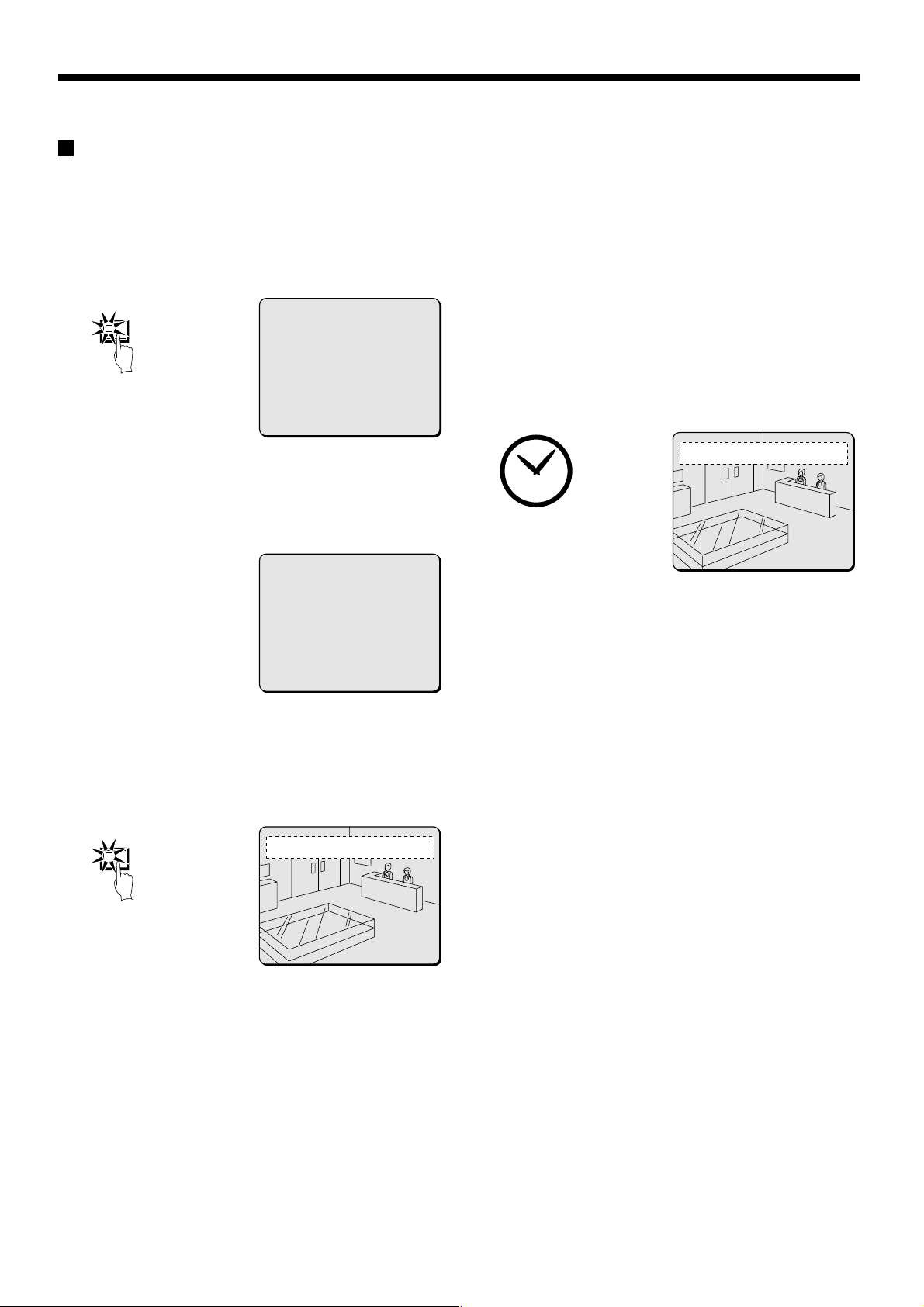
Alarm recording
Alarm images are
recorded
1
Setting the time
1
Press the MENU button to display the LANGUAGE/CLOCK SET
menu, and set the date and time. After the setting has been made,
press the EXIT/OSD button, the date and time appear in the
operating display. (See page 44.)
MENU
Set alarm recording.
2
•
Press the MENU button to display the ALARM REC MODE
SET menu in the menu screen. Then change the ALARM
RECORDING setting to the desired alarm recording setting
(ENABLED, AL-REC ON TIMER, AL-REC OFF TIMER or OLY
AL-RC ON TMR) and change the ALARM TRIGGER setting.
(See page 59.)
•
Press the EXIT/OSD button to return to the normal screen.
<LANGUAGE/LANGUE/SPRACHE/IDIOMA>
ENGLISH
<CLOCK SET>
01-01-2002 TUE 00:00:00
<SUMMER TIME SET>
MODE : USE
WEEK MONTH TIME
ON LST-SUN 03 02:00
OFF LST-SUN 10 02:00
<EXT.CLOCK SET>
ADJUST.TIME 01:00
<ALARM REC MODE SET>
PICTURE QUALITY : SUPER FINE
AUDIO RECORDING : ON
ALARM RECORDING : ENABLED
ALARM INTERLEAVE : ONLY
PROGRAM GROUP : OFF
REC RATE: @ 0.1FPS, DURATION: 40SEC
PRE-ALARM RECORDING : ON
REC RATE:@ *** FPS, DURATION: ***
=> (01010 ALARMS CAN BE RECORDED )
ALARM TRIGGER : ALARM
3
Ending alarm recording
After the end of the alarm duration period (default setting: 5 sec),
the “REC” and “ALARM” displays stop flashing and recording
stops.
2
Suspicious person detection
When an alarm occurs, “ALARM” appears in the operating display,
the ALARM indicator flashes and alarm recording (REC symbol)
starts. Alarm images are recorded in the alarm recording area.
Furthermore, the number of alarms in the operating display is
increased by one each time an alarm occurs.
01
ALARM
Note: Normal recording and timer recording stop when an alarm
occurs during normal recording or timer recording.
REC ALARM 0001 REPEAT EN 10-05-02 18:10:25
The number of
alarms is counted.
22
English
RECORDING IMAGES IN THE ALARM
RECORDING AREA
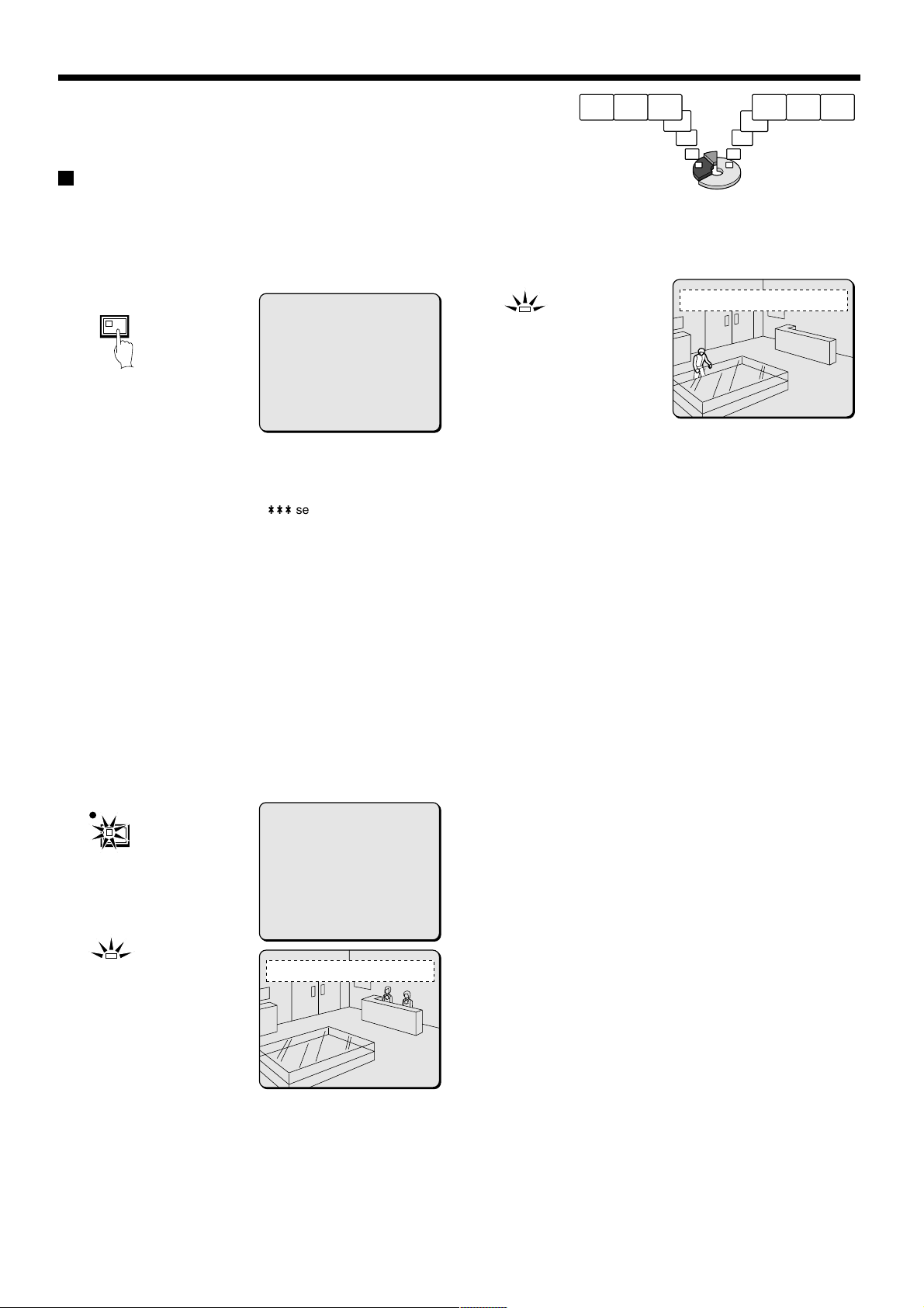
Pre-alarm recording
1
Setting the time
Press the MENU button to display the LANGUAGE/CLOCK SET
menu, and set the date and time. After the setting has been made,
press the EXIT/OSD button, the date and time appear in the
operating display. (See page 44.)
MENU
2
Set pre-alarm recording.
Press the MENU button to display the ALARM REC MODE SET
menu. Set ALARM RECORDING to the desired alarm recording
setting (example: ENABLED). The
RECORDING will be set to “OFF”, so change it to “ON”. (See page
62.)
Press the EXIT/OSD button to return to the normal screen. “PRE”
appears in the operating display, the ALARM indicator illuminates
and pre-alarm recording starts (the REC mark does not appear).
The same monitored image as in the normal recording area is
recorded repeatedly in the alarm recording area.
Recording onto the hard disk proceeds automatically (default
setting) according to the following settings. The settings can be
changed between long-period recording and high-quality recording
in five steps. (See page 59.)
•
Hard disk recording areas:
Normal recording area: 80%
Alarm recording area: 19%
Archive area: 1%
•
Picture quality: EN (Enhanced)
•
Recording speed: 8.33 FPS (81H)
<LANGUAGE/LANGUE/SPRACHE/IDIOMA>
ENGLISH
<CLOCK SET>
01-01-2002 TUE 00:00:00
<SUMMER TIME SET>
MODE : USE
WEEK MONTH TIME
ON LST-SUN 03 02:00
OFF LST-SUN 10 02:00
<EXT.CLOCK SET>
ADJUST.TIME 01:00
***
setting for PRE-ALARM
Pre-alarm images
are recorded
3
When an alarm is received, pre-alarm recording stops
automatically and the alarm images are recorded.
The “PRE” disappears from the operating display, “ALARM”
flashes and the ALARM indicator flashes.
01
ALARM
REC ALARM 0001 REPEAT EN 10-06-02 09:30:15
Monitored images
are recorded
English
REC/STOP
ALARM
<ALARM REC MODE SET>
PICTURE QUALITY : SUPER FINE
AUDIO RECORDING : ON
ALARM RECORDING : ENABLED
ALARM INTERLEAVE : ONLY
PROGRAM GROUP : OFF
REC RATE: @ 0.1FPS, DURATION: 40SEC
PRE-ALARM RECORDING : ON
REC RATE:@ *** FPS, DURATION: ***
=> (01010 ALARMS CAN BE RECORDED )
ALARM TRIGGER : ALARM
01
REC PRE 0000 REPEAT EN 10-05-02 18:10:25
23
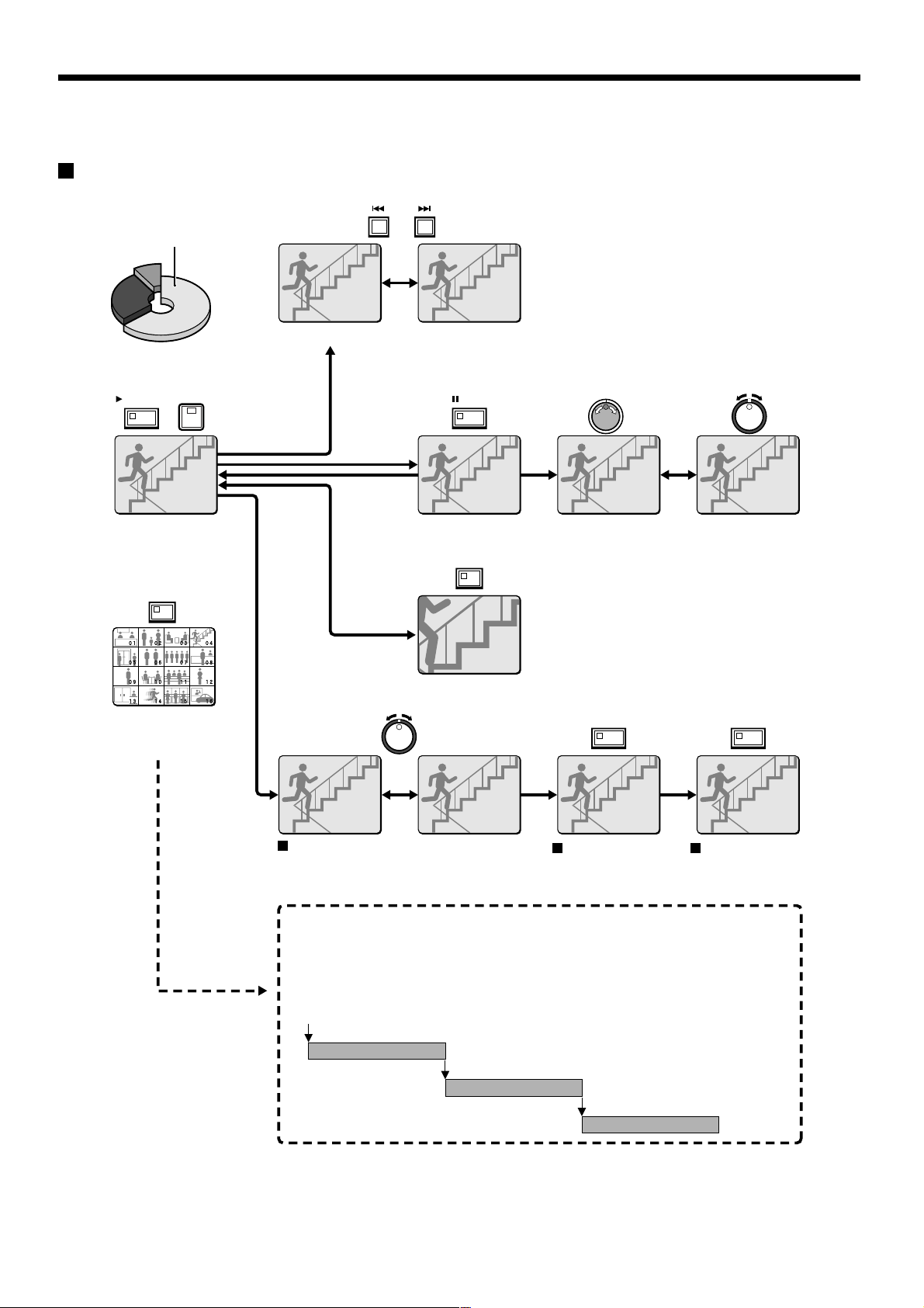
PLAYING BACK RECORDED IMAGES
The digital video recorder can play back recorded images in the normal recording area (normal recording, timer recording).
Playback operations
ALARM
Normal recording area
b Skipping to the previous or next alarm
PLAY/STOP
b
Playback in a single
screen (See page
25.)
b
Playback in multiscreen display
(See page 27.)
4
MULT
STILL
b Still image
(See page 26.)
ZOOM
b Zooming images (See page 26.)
Fast forward/fast rewind and reverse
playback (See page 25.)
b Frame advance
(forward/reverse)
(See page 26.)
SHUTTLE HOLD SHUTTLE HOLD
Locking speed for
fast forward/rewind
playback
(See page 25.)
b
Slow playback
and fast
forward/fast
rewind playback
(See page 25.)
Releasing speed
lock
Normal playback
• When playing back recordings for the first time:
The recorded images will be played back from the beginning.
• When playing back for the second or subsequent time:
Playback will start from the point where the last playback session ended.
(Starting point for
first playback)
Ending point
(Starting point for
second playback)
Ending point
(Starting point for
third playback)
24
Ending point
English
PLAYING BACK RECORDED IMAGES
04
EN 27-10-02 13:38:33
04
EN 20-11-02 04:00:00
01
EN 17-11-02 02:38:00
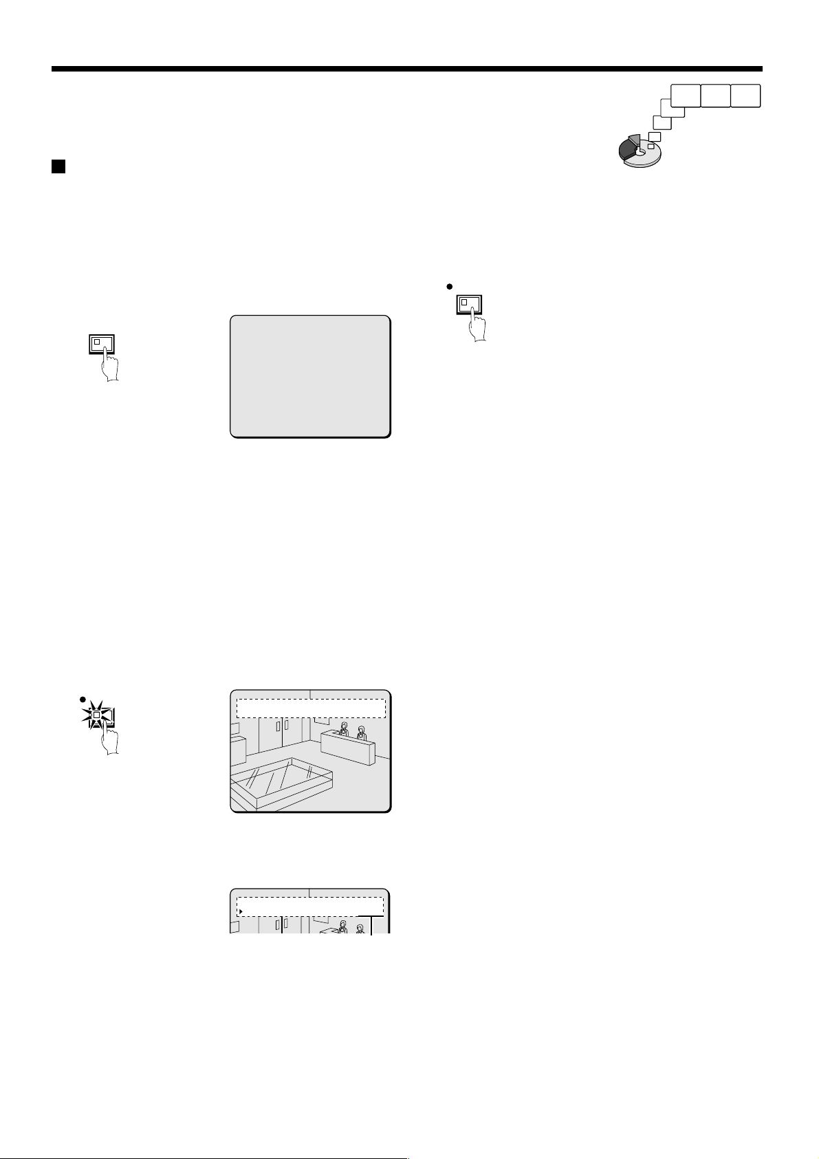
Playback in a single screen
1
Press the PLAY/STOP button.
c appears in the operating display and the images recorded in the
normal recording area are played back.
You can press the camera select buttons to select the camera
images to be played back.
PLAY/STOP
4
01
EN 26-10-02 11:02:50
04
04
EN 27-10-02 13:38:33
EN 27-10-02 13:38:33
Fast forward/fast rewind and reverse playback
1
Turn the shuttle dial clockwise (or counterclockwise) during
playback.
When the shuttle dial is turned clockwise, e appears in the
operating display and fast forward playback starts. If it is turned
counterclockwise, f appears in the operating display and
rewind playback starts.
When you release the shuttle dial, normal playback resumes.
01
01
EN 17-11-02 02:38:00
EN 17-11-02 02:38:00
2
Changing the playback speed
(Fast forward/slow playback)
3
22
Note:
Image playback starts from the point (time) that the recording
•
started.
If there is no starting position, or if a reset has been made, the
oldest recorded image is played back.
When playback is finished, playback mode is automatically paused.
•
The pause (h) symbol appears in the operating display and the
STILL indicator illuminates.
If playback has been carried out at least once, playback will start
•
from the position where the last playback session ended.
2
Press the PLAY/STOP button again.
Playback stops.
PLAY/STOP
Note: If playback is started just as recording is being carried out,
recording will have priority, so that the playback images may be
paused momentarily.
04
04
EN 20-11-02 04:00:00
EN 20-11-02 04:00:00
1 Turn the jog dial clockwise.
Fast forward playback starts and e appears in the operating
display.
2 Turn the jog dial counterclockwise.
Slow playback starts and hc appears in the operating display.
3 Return to normal playback.
Turn the jog dial clockwise. c appears in the operating display.
(Fast rewind playback)
1
2
3
4
1
Turn the shuttle dial counterclockwise slightly (fix at fast rewind)
d will be displayed, so press the SHUTTLE HOLD button. The
SHUTTLE HOLD indicator will illuminate and the rewind playback
speed will be fixed at the current speed.
SHUTTLE HOLD
2 Turn the shuttle dial counterclockwise again.
The speed becomes faster than for normal rewind playback, and
f appears in the operating display.
3 Turn the jog dial clockwise.
e appears in the operating display.
4 Return to normal playback.
Turn the jog dial counterclockwise. c appears in the operating
display.
English
25
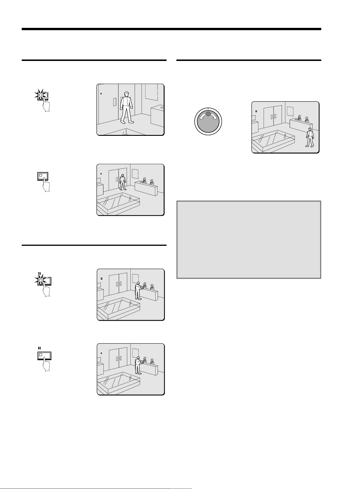
PLAYING BACK RECORDED IMAGES
01
EN 17-11-02 02:36:00
01
EN 17-11-02 02:36:10
01
EN 17-11-02 02:38:00
01
EN 17-11-02 02:38:20
01
EN 17-11-02 02:50:08
Zooming the image during playback
1
Press the ZOOM button during playback.
The images will be enlarged.
ZOOM
2
To return an enlarged image to normal image display, press
the ZOOM button once more.
The zoom will be canceled and normal images will appear.
ZOOM
Note: You can also change the zoom position. For details on this
operation, refer to “Enlarging images” (See page 15).
01
01
EN 17-11-02 02:36:00
EN 17-11-02 02:36:00
01
01
EN 17-11-02 02:36:10
EN 17-11-02 02:36:10
Viewing still images
1
Press the STILL button during playback.
h appears in the operating display and a still image is displayed.
STILL
01
01
EN 17-11-02 02:38:00
EN 17-11-02 02:38:00
Frame advance (forward/reverse)
1
Turn the jog dial clockwise (or counterclockwise) in still mode.
Turn the jog dial clockwise to advance the still image by one frame
(one field).
Turn it counterclockwise to rewind the still image by one frame
(one field).
01
01
EN 17-11-02 02:50:08
EN 17-11-02 02:50:08
Note: If the jog dial is turned quickly, the frame feed speed also
increases. However, if the speed is too fast, the images will
stop. Play back the images at an appropriate speed.
During the following operations the picture may appear
distorted or momentarily frozen. This is normal and not a
malfunction.
During the continuous playback from the normal and the
•
alarm recording area, the picture may be distorted when the
recording area is switched.
When playing back during an alarm recording, during
•
continuous playback from the normal and alarm recording
area, during normal playback or when using the fast
forward/rewind playback the picture may appear
momentarily frozen.
2
Press the STILL button once more.
Still mode is canceled.
STILL
01
01
EN 17-11-02 02:38:20
EN 17-11-02 02:38:20
26
English
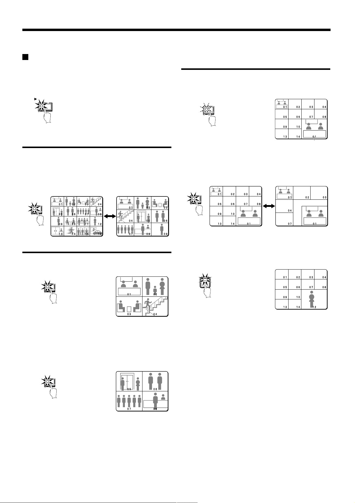
PLAYING BACK RECORDED IMAGES
Playing back multiple-screen displays
Recorded images can be playback in several split-screen formats.
Furthermore, the images from each camera can be displayed in any
position within the split-screen. (See page 81.)
1
Press the PLAY/STOP button.
PLAY/STOP
Playing back images as 9-screen or 16-screen
displays
1
Press the MULTI button.
The display switches between 9-screen and 16-screen each time
the MULTI button is pressed.
To return to a single-screen display, press a camera select button.
For the DSR-3009P model, only the 9-screen display is available
with no switching.
MULT
Playing back images as 13-screen or 6-screen
displays (plus screen)
1
Press the PLUS button.
The display changes to show a 13-screen or 6-screen display with
a plus screen as a quarter-screen picture in the lower-right corner.
PLUS
Plus screen
2
Press the MULTI button.
The display switches between 13-screen and 6-screen each time
the MULTI button is pressed.
For the DSR-3009P model, only the 6-screen display is available
with no switching.
MULT
Playing back images as a 4-screen display
1
Press the QUAD button.
Images appear as a 4-screen display.
QUAD
2
Press the QUAD button once more.
Camera images are switched in 4-screen display units (1 – 4, 5 – 8,
9 – 12, 13 – 16) each time the button is pressed.
To return to a single-screen display, press a camera select button.
For the DSR-3009P model, a 4-screen display of images from
cameras 1 – 4, 5 – 8, or 9 – 3 will appear each time the button is
pressed.
QUAD
3
Press a camera select button (example: 12).
The playing back images from the selected camera will be
displayed in the plus screen.
To cancel the plus screen, press the PLUS button once more.
For the DSR-3009P model, press camera select button 9.
12
English
27
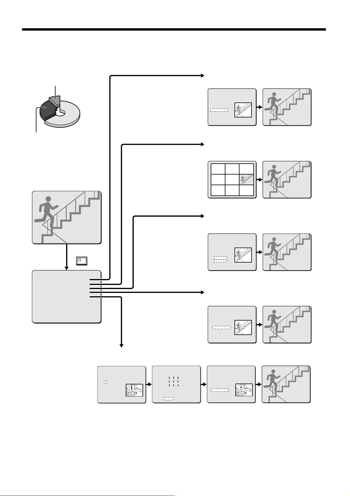
SEARCHING FOR RECORDED IMAGES
Images that have been recorded in the alarm recording area and in the archive area can be played back. Furthermore, images can also be
searched for by recording date and time, and you can also search for moving objects that have been detected by a motion sensor during image
playback.
a Alarm search (See page 29.)
Archive area
Alarm recording area
Alarm image search and playback
<ALARM SEARCH>
NO DATE TIME CH TOTAL ALARMS
0101 13-12 11:13 16 00234
0102 13-12 11:15 10
0103 13-12 15:19 06
0104 15-12 10:13 01
0105 16-12 16:13 03 SEARCHING
0106 16-12 11:13 12
0107 19-12 14:23 10
0108 20-12 05:37 04
MOVE:JOG SELECT:SHUTTLE
Preview display Single-screen display
a Alarm image thumbnail search (See page 30.)
Alarm image thumbnail search and
playback
0101 0102 0103
0104 0105 0106
0107 0108 0109
Single-screen displayThumbnail display
SEARCH
<SEARCH>
ALARM SEARCH ->
ALARM THUMBNAIL SEARCH ->
TIME/DATE SEARCH ->
ARCHIVE AREA SEARCH ->
MOTION DETECTION SEARCH ->
MOVE:JOG SELECT:SHUTTLE
a Motion detection search (See page 32.)
Searching for and playing back moving objects detected by a motion sensor
<MOTION DETECTION SEARCH>
SEARCH FROM : NORMAL / CHANNEL : 4
START :
28-10-01 08:00
END :
28-10-01 20:00
MOTION SENSOR ->
PREVIEW ->
VIEW ->
MOVE:JOG SELECT:SHUTTLE
for motion detection
a Time/date search (See page 30.)
Searching and playing back recorded
images by date/time
<TIME/DATE SEARCH>
RECORDING TOP : 15-12-00 08:00
RECORDING END : 22-12-00 17:00
CHANNEL : - SEARCH :
DATE TIME
20-12-00 05:37 SEARCHING
PREVIEW ->
VIEW ->
CHANGE:JOG SET:SHUTTLE
a Archive area search (See page 31.)
Playing back images saved (copied) in
the archive area
<ARCHIVE AREA SEARCH>
NO DATE TIME CH CAPACITY
0011 13-12 11:13 01 TOTAL - 1024MB
0012 13-12 11:15 01 USED - 400MB
0013 13-12 15:19 01
0014 15-12 10:13 01
0015 16-12 16:13 01 SEARCHING
0016 16-12 11:13 01
0017 19-12 14:23 01
0018 20-12 05:37 01
MOVE:JOG SELECT:SHUTTLE
----------
----------
---úúú----
---úúú----
---úúú----
----------
----------
----------
LEVEL : 6 EXIT
Motion sensor setting Single-screen displayDate/time search of an image
<MOTION DETECTION SEARCH>
SEARCH FROM : NORMAL / CHANNEL : 4
START :
28-10-01 10:00
END :
28-10-01 20:00
MOTION SENSOR ->
PREVIEW ->
VIEW ->
MOVE:JOG SELECT:SHUTTLE
Preview display
Single-screen displayPreview display
Single-screen displayPreview display
28
English
 Loading...