

Page 1
L8HBA_US(DSR-3016 NETWORK)(GB only).book 1 ページ 2003年3月28日 金曜日 午後6時44分
Digital Video Recorder
Manual for Remote Operation by Network Connection
DSR-3016
DSR-3009
Page 2

L8HBA_US(DSR-3016 NETWORK)(GB only).book 1 ページ 2003年3月28日 金曜日 午後6時44分
Contents
Network Control Functions . . . . . . . . . . . 3
Basic Specifications for Network Control. . . . 3
Network Settings . . . . . . . . . . . . . . . . . . . . . . 3
Network Control . . . . . . . . . . . . . . . . . . . 4
Controling by Computer via Network . . . . . . . 4
Controling by Main Unit . . . . . . . . . . . . . . . . . 4
Displays That Appear While Connected . . . . 5
Operating Panel and Operation
Permissions . . . . . . . . . . . . . . . . . . . . . . 6
Settings . . . . . . . . . . . . . . . . . . . . . . . . . 7
Menu Selection Method . . . . . . . . . . . . . . . . . 7
Menu Configuration . . . . . . . . . . . . . . . . . . . . 7
Menu Setting Procedures. . . . . . . . . . . . 8
1. CLOCK SET . . . . . . . . . . . . . . . . . . . . . . . 8
2. DAYLIGHT SAVING/EXT. CLOCK SET. . 8
3. PROGRAM REC SET . . . . . . . . . . . . . . . 9
4. RECORDING AREA SET. . . . . . . . . . . . 10
5. RECORDING CONDITIONS SET . . . . . 11
NORMAL RECORDING AREA OVERWRITE . . . . .11
ALARM RECORDING AREA OVERWRITE . . . . . .11
REMAINING DISK WARNING. . . . . . . . . . . . . . . . .11
6. NORMAL REC MODE SET . . . . . . . . . . 12
PICTURE QUALITY. . . . . . . . . . . . . . . . . . . . . . . . .12
AUDIO RECORDING. . . . . . . . . . . . . . . . . . . . . . . .12
REC RATE. . . . . . . . . . . . . . . . . . . . . . . . . . . . . . . .13
REC PROGRAM GROUP . . . . . . . . . . . . . . . . . . . .13
7. TIMER SET . . . . . . . . . . . . . . . . . . . . . . 14
8. HOLIDAY SET . . . . . . . . . . . . . . . . . . . . 15
9. ALARM REC MODE SET . . . . . . . . . . . 15
PICTURE QUALITY. . . . . . . . . . . . . . . . . . . . . . . . . 15
AUDIO RECORDING . . . . . . . . . . . . . . . . . . . . . . . 15
ALARM RECORDING . . . . . . . . . . . . . . . . . . . . . . . 16
PRE-ALARM RECORDING. . . . . . . . . . . . . . . . . . . 17
ALARM TRIGGER. . . . . . . . . . . . . . . . . . . . . . . . . . 17
10.ALARM DURATION SET . . . . . . . . . . . 18
11.DISPLAY SET . . . . . . . . . . . . . . . . . . . . 18
DATE . . . . . . . . . . . . . . . . . . . . . . . . . . . . . . . . . . . . 18
TIME . . . . . . . . . . . . . . . . . . . . . . . . . . . . . . . . . . . . 18
QUALITY . . . . . . . . . . . . . . . . . . . . . . . . . . . . . . . . . 18
AUDIO . . . . . . . . . . . . . . . . . . . . . . . . . . . . . . . . . . . 18
ALARM COUNT. . . . . . . . . . . . . . . . . . . . . . . . . . . . 18
ALARM TYPE . . . . . . . . . . . . . . . . . . . . . . . . . . . . . 18
12.RS-232C/RS-485 SET. . . . . . . . . . . . . . 19
CONTROL . . . . . . . . . . . . . . . . . . . . . . . . . . . . . . . . 19
DATA SPEED . . . . . . . . . . . . . . . . . . . . . . . . . . . . . 19
STATUS INFO. . . . . . . . . . . . . . . . . . . . . . . . . . . . . 19
ALARM INFO. . . . . . . . . . . . . . . . . . . . . . . . . . . . . . 19
ADDRESS . . . . . . . . . . . . . . . . . . . . . . . . . . . . . . . . 19
13.BUZZER SET . . . . . . . . . . . . . . . . . . . . 19
ALARM . . . . . . . . . . . . . . . . . . . . . . . . . . . . . . . . . . 19
DISK FULL. . . . . . . . . . . . . . . . . . . . . . . . . . . . . . . . 19
DISK ERROR . . . . . . . . . . . . . . . . . . . . . . . . . . . . . 19
LOCK WARNING. . . . . . . . . . . . . . . . . . . . . . . . . . . 19
KEY IN. . . . . . . . . . . . . . . . . . . . . . . . . . . . . . . . . . . 19
NON REC . . . . . . . . . . . . . . . . . . . . . . . . . . . . . . . . 19
14.NETWORK SET . . . . . . . . . . . . . . . . . . 20
IP ADDRESS. . . . . . . . . . . . . . . . . . . . . . . . . . . . . . 20
SUBNET MASK. . . . . . . . . . . . . . . . . . . . . . . . . . . . 20
GATE WAY . . . . . . . . . . . . . . . . . . . . . . . . . . . . . . . 20
PORT. . . . . . . . . . . . . . . . . . . . . . . . . . . . . . . . . . . . 20
PASSWORD SETTING. . . . . . . . . . . . . . . . . . . . . .20
NETWORK SPEED . . . . . . . . . . . . . . . . . . . . . . . . . 20
15.HDD SET . . . . . . . . . . . . . . . . . . . . . . . . 21
PLAYBACK DRIVE . . . . . . . . . . . . . . . . . . . . . . . . . 21
16.POWER FAILURE/USED TIME . . . . . . 21
English
1
Page 3
L8HBA_US(DSR-3016 NETWORK)(GB only).book 2 ページ 2003年3月28日 金曜日 午後6時44分
Recording Images . . . . . . . . . . . . . . . . 22
Normal recording . . . . . . . . . . . . . . . . . . . . . 22
Timer recording . . . . . . . . . . . . . . . . . . . . . . 22
Alarm recording . . . . . . . . . . . . . . . . . . . . . . 23
Pre-alarm recording . . . . . . . . . . . . . . . . . . . 23
Viewing Images . . . . . . . . . . . . . . . . . . 24
Viewing Live Images . . . . . . . . . . . . . . . . . . 24
Playing Back Recorded Images. . . . . . . . . . 24
Specifying the Number of Display Screens . 25
Playback Mode Operations . . . . . . . . . . . . . 25
Image Adjustment and Audio Playback . . . . 26
On-screen Display Items . . . . . . . . . . . . . . . 27
Search . . . . . . . . . . . . . . . . . . . . . . . . . 28
Basic Search Operations . . . . . . . . . . . . . . . 28
Search Menus . . . . . . . . . . . . . . . . . . . . . . . 28
Search Mode Operations . . . . . . . . . . . 29
1. ALARM SEARCH . . . . . . . . . . . . . . . . . . 29
2. ALARM THUMBNAIL SEARCH . . . . . . . 29
3. TIME/DATE SEARCH . . . . . . . . . . . . . . . 30
4. ARCHIVE AREA SEARCH . . . . . . . . . . . 30
5. MOTION DETECTION SEARCH . . . . . . 31
Saving Recorded Images and Sound . . 32
COPY TO ARCHIVE AREA ON THE
RECORDER . . . . . . . . . . . . . . . . . . . . . . . . 32
DOWNLOAD TO PC . . . . . . . . . . . . . . . . . . 33
DVR Viewer. . . . . . . . . . . . . . . . . . . . . . 35
Operating environment . . . . . . . . . . . . . . . . 35
Installing the DVR Viewer . . . . . . . . . . . . . . 35
Opening and closing DVR Viewer. . . . . . . . 36
Menu structure . . . . . . . . . . . . . . . . . . . . . . 37
Opening files . . . . . . . . . . . . . . . . . . . . . . . . 38
Viewing images . . . . . . . . . . . . . . . . . . . . . . 39
Printing images . . . . . . . . . . . . . . . . . . . . . . 41
Saving images . . . . . . . . . . . . . . . . . . . . . . 42
<Symbols used in this manual>
Cautions
Notes
Main menu
Sub-menu
Saving setting values for a whole menu screen
COPYRIGHTS
This manual and the software are copyrighted materials from Sanyo Electric Co., Ltd. © 2002.
Microsoft, Windows, and Windows NT are registered trademarks of Microsoft Corporation.
Internet Explorer is a registered trademark of Microsoft Corporation.
All other brand or products names mentioned in this manual are trademarks or registered trademarks of their respective companies.
2
English
Page 4
L8HBA_US(DSR-3016 NETWORK)(GB only).book 3 ページ 2003年3月28日 金曜日 午後6時44分
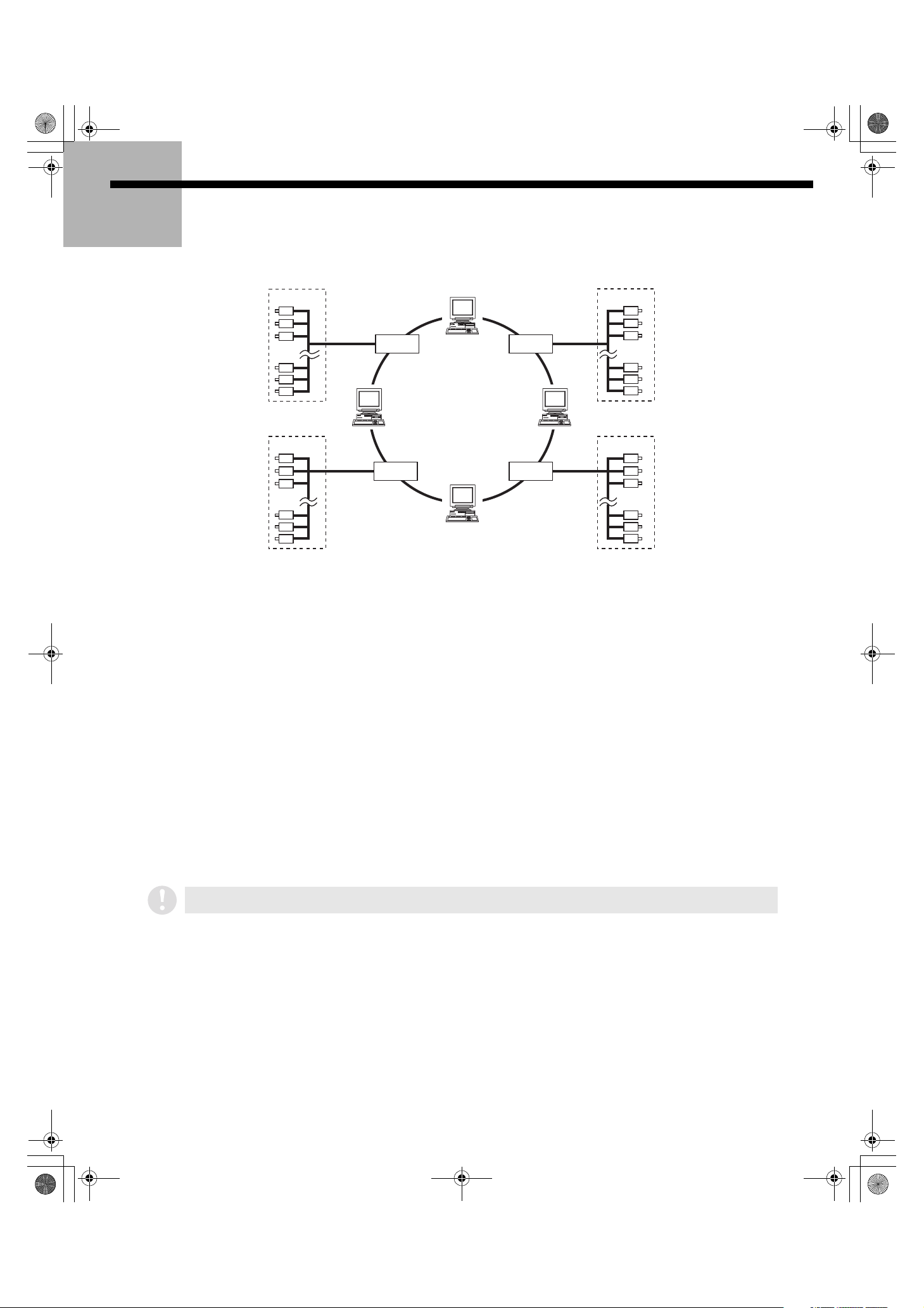
Network Control Functions
Connecting this unit to a network will enable computer control (remote operation).
CAMERA
1
DVR 2 DVR 3
4
DVR 1 DVR 4
3
2
CAMERA
CAMERACAMERA
(DVR: Digital Video Recorder)
■■■■ Basic Specifications for Network Control
1. Operations such as menu settings, recording and playback can be done on the computer screen.
Furthermore, the multiplexer function allows images from multiple cameras that are connected to the
main unit to be displayed in multi-screen format on the computer’s screen.
2. Up to a total of four computers can be connected simultaneously to a single digital video recorder
(DVR): 3 computers that are connected while logged in at a user level of ID1, and one other computer
that is logged in at a user level of ID2 or ID3.
3. Control can be switched freely between main unit control and computer control as required.
Simply connecting a cable will not affect the operation of the main unit.
4. For security over computer control, identity checks (passwords) can be specified for three user levels.
■■■■ Network Settings
1. The following main unit network settings must be made beforehand if this unit is to be used when
connected to a network. Refer to “Network Set settings” in the main unit Instruction Manual for details
on how to make the settings.
2. Also change the TCP/IP settings for the computers that are connected in accordance with the
operating system (OS) that is being used by these computers.
If using an existing network, the IP address that you set must not be the same as an existing IP address being used on the
network. Check with the network administrator for details.
Saving and playing back sound
b
• To save and play back sound using a computer that is part of the network, you must have Active X for both saving and playing
back sound installed on each system. You can download the Active Allinstall application that installs both types of Active X at the
same time from the Sanyo website at the URL given below.
• To playback images and sound that have been downloaded onto a computer, CompactFlash card or CD-R, you can download an
accessory playback application called DVR Viewer (Ver. 1.4 or later) from the Sanyo website at the URL given below. (See p35)
Sanyo website URL: http://www.sanyosecurity.com
Minimum system requirements
b
Operating system: Windows 98 / 98SE / Me / 2000 / XP
Browser: Internet Explorer Ver. 5.0 or later
Video: 65,000 colors, resolution 800 x 600 dpi or higher
English
Audio playback requirements
b
DirectX or compatible sound card
Speaker
3
Page 5

L8HBA_US(DSR-3016 NETWORK)(GB only).book 4 ページ 2003年3月28日 金曜日 午後6時44分
Network Control
■■■■ Controling by Computer via Network
Start your Web browser.
1
Compatible browsers are Internet Explorer Ver. 5.0 or later.
Compatible operating systems are Windows 98, 98SE, Me,
2000 and XP.
If a Java Script run-time error appears while using
Internet Explorer, change the settings for Internet
Explorer as shown below.
1. Select Internet Options from the Tools menu,
and click the Advanced tab.
2. Make sure that the following check boxes are set
as indicated.
2
Enter the URL.
Enter the URL for this unit in the address bar of the browser, and
then press the [Enter] key. Enter the IP address specified in the
network setting for this unit. (The URL contains the IP address
that has been set for this unit in the network settings.)
Enter the default value 192.168.0.1.
(Example: “http://192.168.0.1/”)
If the port is set to a value other than the default
value of “80”, add a “:” followed by the port number
to the end of the IP address.
Example if the port is set to “81”
http://192.168.0.1:81/
(3) Up to a total of four computers can be connected
(4) If you make more than one error entering the
(5) If you click a button on the control panel that you are
4
Select the display language.
When the security check for the password has been cleared,
the language selection screen will appear. Select a language
and then click [OK]. The operating screen will be displayed in
the selected language and computer control will be enabled.
simultaneously to a single digital video recorder.
(However, only one computer can be connected at a
user level of ID2 or ID3.)
If the highest-level user connects from a different
computer while four computers are already
connected, the last one of the lowest-level
computers to connect is forcibly disconnected and
the highest-level user has priority.
password or if you click the [Cancel] button in the
password entry screen, an “AUTHENTICATION
ERROR” window will be displayed.
not authorized to use during computer control, the
password entry screen will be displayed and you will
be prompted for a security check for the required
user level for that function.
If you do not have a web browser installed on your
computer’s hard disk, you will need to install one.
3
Enter a password (security check).
Enter your user name and password for security checking in
the Network password entry box, and then click [OK].
If you enter an incorrect password, the password entry screen
will reappear asking you to re-enter the password.
(1) Select the display language each time you switch to
computer control.
(2) To change the display language, cancel the
connection temporarily and then reconnect.
(1) You should use separate passwords for different
user levels In accordance with the installation
environment. (See p. 20)
(2) If you choose to save the user name and password that
you enter, the security check will be cleared automatically
the next time you log on. However, passwords that were
entered at some time other than the time when you first
connected may not be stored in some cases.
Controling by Main Unit
■■■■
IMPORTANT
• You cannot connect to the network while a menu screen is being
displayed or when operations associated with playback are
being carried out. Clear the menu display or stop the playback
operation before reconnecting to the network.
• In some cases, you may encounter problems when
connecting to the network via a proxy server. If this
happens, the proxy setting should be canceled.
When you click the S button on the computer operating screen, the connection will be canceled and control will
switch to the main unit.
• If you close the browser without clicking the S button, you will need to wait for at least 1 minute before
reconnecting.
• To forcibly cancel the connection from the main unit, press the [EXIT/OSD] button for two seconds or more. No
connections will be received by the computer for 10 seconds after the connection has been forcibly canceled.
• If communication with the computer is suspended for one minute or more, the connection will be automatically
cancelled and control will switch to the main unit.
4
English
Page 6
L8HBA_US(DSR-3016 NETWORK)(GB only).book 5 ページ 2003年3月28日 金曜日 午後6時44分
Network Control
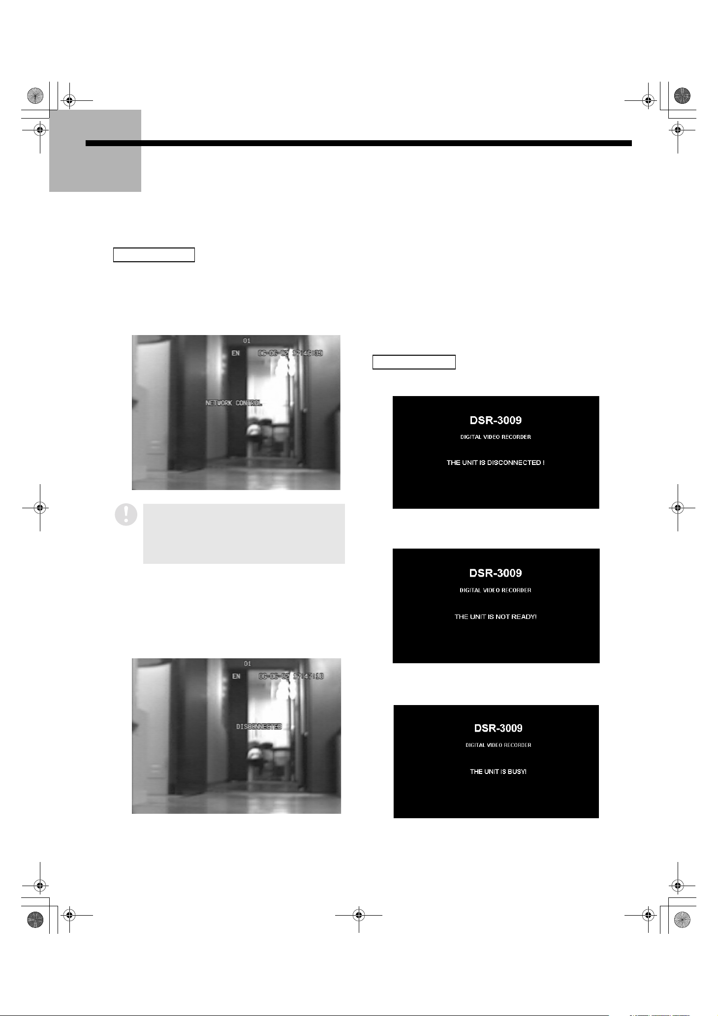
■■■■ Displays That Appear While Connected
Messages appear on the screen for a short period to indicate control switching and network connection status.
Main unit display
1. When control is switched to a computer
When the web browser is started and the specified procedure
is followed, operation switches to the computer and
“NETWORK CONTROL” appears on the main unit on-screen
display. (This appears even if on-screen display has been set
to “OFF”.)
3. When the connection is forcibly canceled from the
main unit
Pressing the [EXIT/OSD] button on the main unit for two
seconds or more will forcibly cancel the connection and cause
the “NETWORK CONTROL” display to disappear.
No connections will be received by the computer for 10
seconds after the connection has been forcibly canceled.
Computer display
1. When disconnected from the network
If the network control has been set to “ON
(DISPLAY: OFF)” using the digital video recorder
menu, the “NETWORK CONTROL” message will not
be displayed. (The digital video recorder will always
display live images regardless of network
operations.)
2. When control is switched to the main unit
When you click the S button at the computer, the
connection is canceled and control is switched to the main
unit, and the main unit on-screen display changes from
“NETWORK CONTROL” to “DISCONNECTED”.
Once the switching is complete, any main unit button
operation will cause the “DISCONNECTED” display to
disappear.
2. If the DVR is accessed while the connection is
disabled
3. When you try to access a DVR that already has four
computers connected
English
* The above screen display examples are those for the DSR-3009
model.
5
Page 7
L8HBA_US(DSR-3016 NETWORK)(GB only).book 6 ページ 2003年3月28日 金曜日 午後6時44分
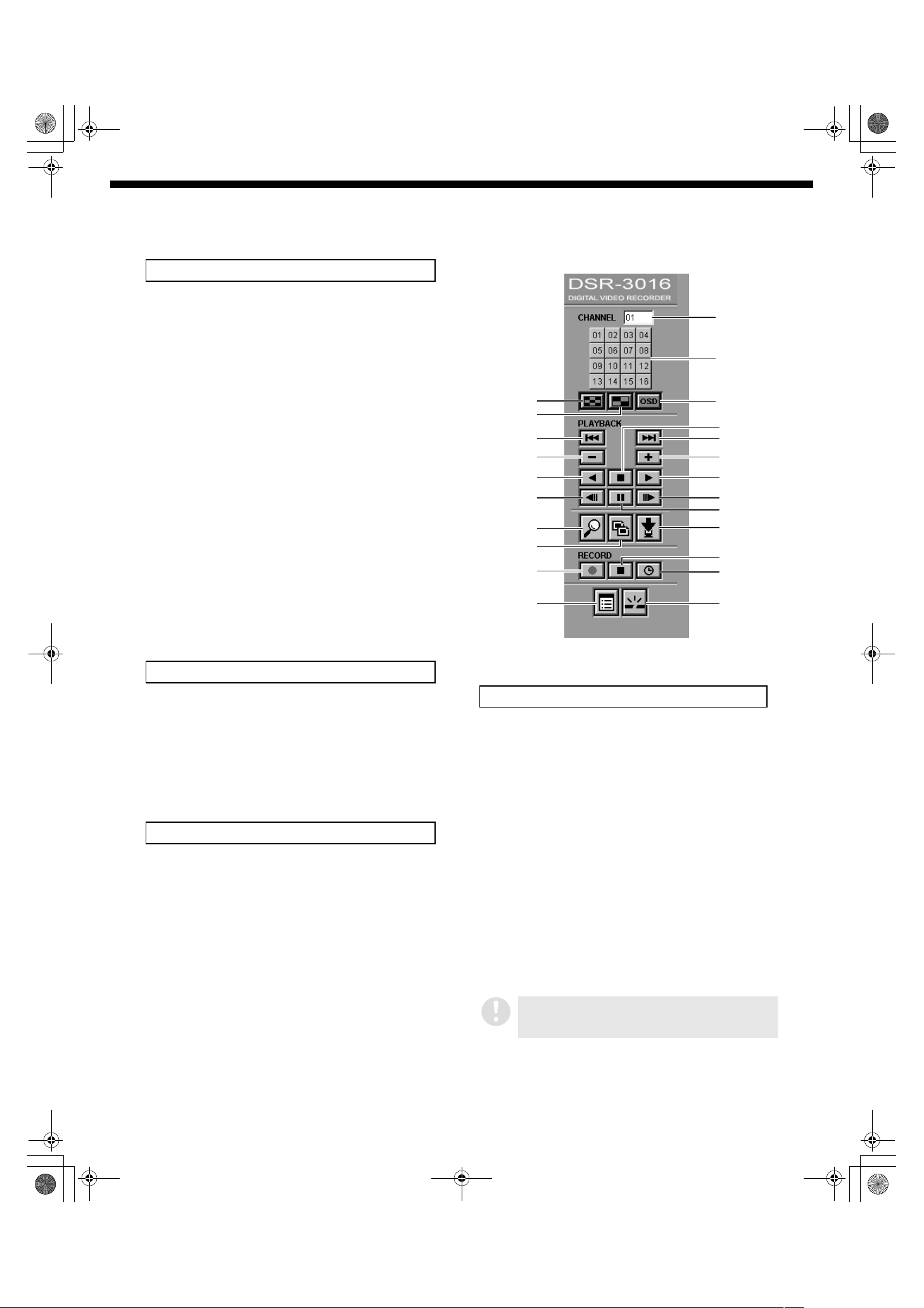
Operating Panel and Operation Permissions
Playback buttons
1 Previous event (ID2/3)
Used to playback from immediately before an alarm event.
2 Next event (ID2/3)
Used to playback from immediately after the next alarm
event.
3 Speed down (ID2/3)
Used to reduce the playback speed by one step.
4 Speed up (ID2/3)
Used to increase the playback speed by one step.
5 Reverse playback (ID2/3)
Used to play back a recorded image in reverse.
6 Stop (ID1/2/3)
Used to stop playback and display live images.
7 Playback (ID2/3)
Used to play back recorded images.
8 Previous image (ID2/3)
Used to return a recorded image by one frame while playback
is paused.
9 Still (ID2/3)
Used to still images during playback.
F Next image (ID2/3)
Used to advance recorded images by one frame while
playback is paused.
Recording buttons
Q
R
1
3
5
8
J
K
G
M
The display example is that for the DSR-3016 model.
P
O
S
6
2
4
7
F
9
L
H
I
N
G Record (ID3)
Used to start normal recording.
H Stop recording (ID3)
Used to stop normal recording.
I Timer (ID3)
If clicked while recording is stopped, the mode changes to
timer standby mode. If clicked during timer standby mode,
timer recording is canceled.
Setting buttons
J Search (ID2/3)
Used to display the search screen (setting screen).
K Copy (ID2/3)
Used to display the copy screen (setting screen).
L Download (ID2/3)
Used to display the download screen (setting screen).
M Menu setting (ID3)
Used to display the menu screen (setting screen).
N Disconnect (ID1/2/3)
Used to disconnect from the network and switch from
computer control to main unit control.
Channel switching buttons
O Channel select (ID1/2/3)
Used to select a camera channel when images are being
displayed in a single screen.
• DSR-3009 model: Maximum 9 channels
• DSR-3016 model: Maximum 16 channels
P Channel display
Used to display the channel number selected by O.
Q Multi display (ID2/3)
Used to display images in a 9-screen or 16-screen multiscreen display.
• DSR-3009 model: 9-screen button
• DSR-3016 model: 16-screen button
R 4-screen display (ID2/3)
Used to display images in a 4-screen multi-screen display.
S OSD Display position change (ID2/3)
Used to change the on-screen display position for information
such as date and time.
OSD display is not available for user level ID1.
If you click on the Multi display or 4-screen display
while logged on at user level ID1, a channel with a
signal will be displayed at random.
* Authorized user levels are indicated in parentheses ( ).
(See p. 20)
6
English
Page 8
L8HBA_US(DSR-3016 NETWORK)(GB only).book 7 ページ 2003年3月28日 金曜日 午後6時44分
Settings
To use the functions of this unit effectively, the recording conditions and installation environment must
be specified beforehand. These setting items are arranged and displayed in two levels consisting of the
main menu and sub-menus.
Refer to the setting procedures for each menu on the following pages for details on the various setting
methods.
■■■■ Menu Selection Method
Click the R button on the operating panel to
1
display the [MAIN MENU] screen.
2
When the specified menu on the [MAIN MENU]
screen is selected and clicked, the sub-menu will
be displayed.
3
Change the required settings from the sub-menu
screen.
4
To clear the menu screen, click the Playback mode
P button on the operating panel to leave the
menu screen and display the live screen.
• Because entry from playback mode is not
possible, click the stop button to return
temporarily to live mode and then click the R
button.
• You must be connected at the ID3 user level in
order to change settings.
• If the main unit is recording, the menu details can
be checked but the settings cannot be changed.
• When moving from one sub-menu to another submenu, first click the R button to return to the
main menu.
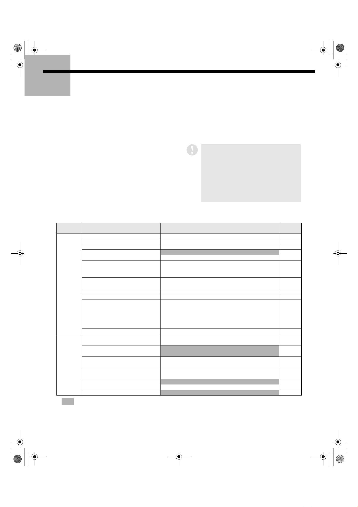
■■■■ Menu Configuration
Main menu Sub-menu
Recording
conditions
Installation
environment
1. CLOCK SET 8
2. DAYLIGHT SAVING/EXT. CLOCK SET • DAYLIGHT SAVING • EXT. CLOCK SET 8
3. PROGRAM REC SET 9
4. RECORDING AREA SET
5. RECORDING CONDITIONS SET • NORMAL RECORDING AREA OVERWRITE
6. NORMAL REC MODE SET • PICTURE QUALITY • AUDIO RECORDING
7. TIMER SET 14
8. HOLIDAY SET 15
9. ALARM REC MODE SET • PICTURE QUALITY • AUDIO RECORDING
10. ALARM DURATION SET 18
11. DISPLAY SET • DATE • TIME • QUALITY • AUDIO
12. RS-232C/RS-485 SET
13. BUZZER SET • ALARM • DISK FULL • DISK ERROR
14. NETWORK SET • IP ADDRESS • SUBNET MASK • GATE WAY • PORT
15. HDD SET
16. POWER FAILURE/USED TIME
Reference
page
• TOTAL CAPACITY • RECORDING AREA CAPACITY 10
• AREA FULL RESET (NORMAL, ALARM, ARCHIVE)
• ALARM RECORDING AREA OVERWRITE
• REMAINING DISK WARNING
• REC RATE • REC PROGRAM GROUP
• ALARM RECORDING (ALARM INTERLEAVE, PROGRAM
GROUP, REC RATE, DURATION)
• PRE-ALARM RECORDING (REC RATE, DURATION)
• ALARM TRIGGER
• ALARM COUNT • ALARM TYPE
• CONTROL • DATA SPEED • STATUS INFO
• ALARM INFO • ADDRESS
• LOCK WARNING • KEY IN • NON REC
• PASSWORD SETTING • NETWORK SPEED
• HARD DISK CAPACITY • MIRRORING
• PLAYBACK DRIVE
• POWER FAILURE • USED TIME • FIRMWARE 21
11
12 to 13
15 to 17
18
19
19
20
21
English
*
Shaded items are for information display only.
7
Page 9
L8HBA_US(DSR-3016 NETWORK)(GB only).book 8 ページ 2003年3月28日 金曜日 午後6時44分
Menu Setting Procedures
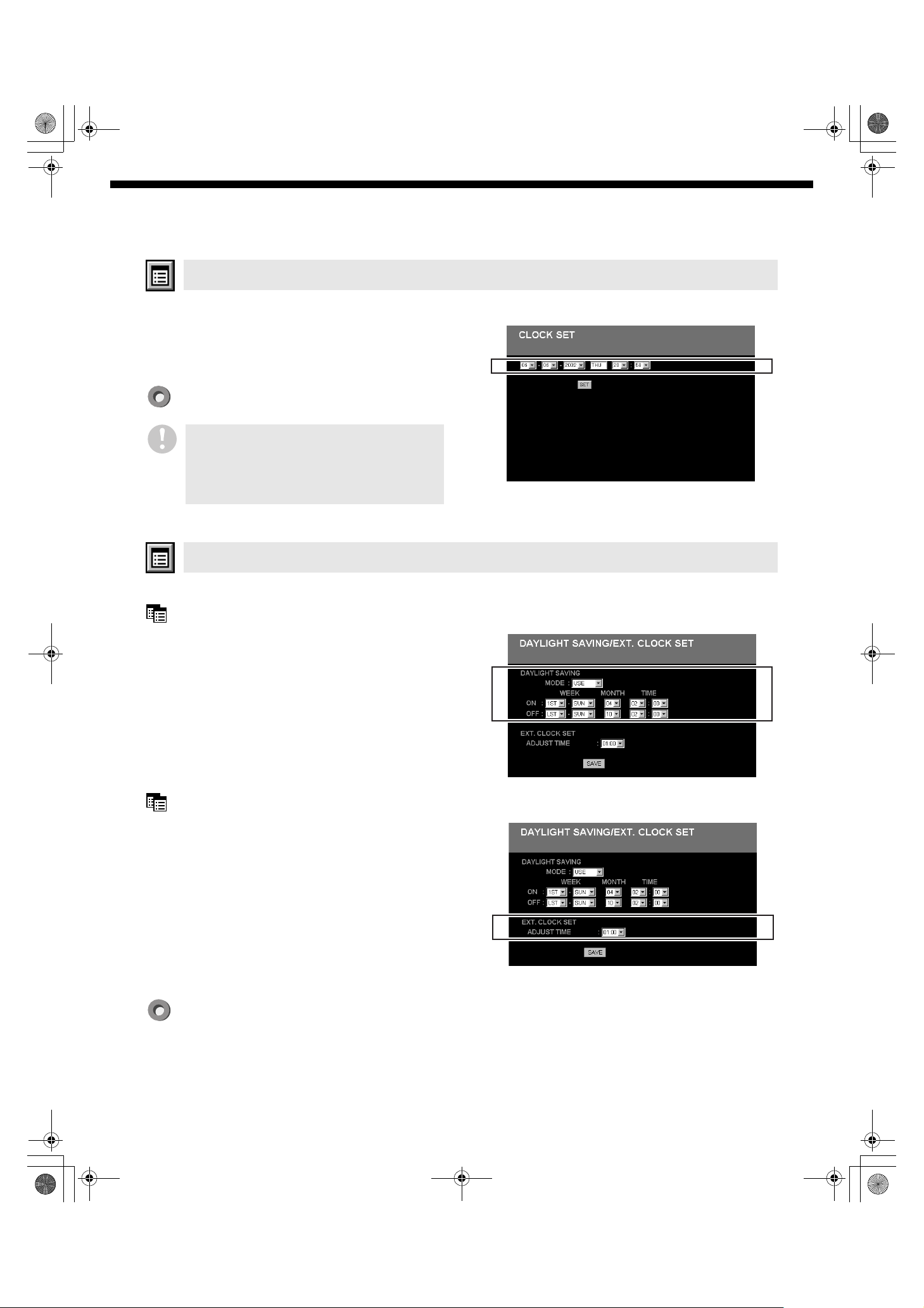
1. CLOCK SET
This sets the main unit clock to the current time.
1
Select “Month/Day/Year Hour/Minute” from the
menu.
The day of the week is selected automatically based on the
date.
Click [SET] to set the time.
The recording mode will not operate if the time has
not been set. If you click on the
button at this time, the following warning
Q
message will be displayed to prompt you to set the
time.
“PLEASE SET THE CLOCK TO START RECORDING”
button or the
O
2. DAYLIGHT SAVING/EXT. CLOCK SET
This sets daylight saving and adjusts the time for peripheral devices.
DAYLIGHT SAVING
This sets the start and end times for daylight saving.
When daylight saving is set, the time will be
automatically advanced by one hour during the
daylight saving period.
1
Use the menu to select “USE” or “NO USE”.
• USE: The daylight saving function is used.
• NO USE: The daylight saving function is not used.
2
Use the menu to set the start time and end time for
daylight saving.
EXT. CLOCK SET
If the times on each peripheral device are different
when the devices are connected, identical operations
cannot be carried out correctly. Making this setting
ensures that each device connected to the CLOCK
ADJUST IN/CLOCK ADJUST OUT connectors will be
set to the same time.
1
Select the adjustment time from the menu.
When the set time is reached every day, a signal is output to
adjust the time for each connected device.
Click [SAVE] to complete the DAYLIGHT SAVING and EXT. CLOCK SET settings.
8
English
Page 10
L8HBA_US(DSR-3016 NETWORK)(GB only).book 9 ページ 2003年3月28日 金曜日 午後6時44分
Menu Setting Procedures
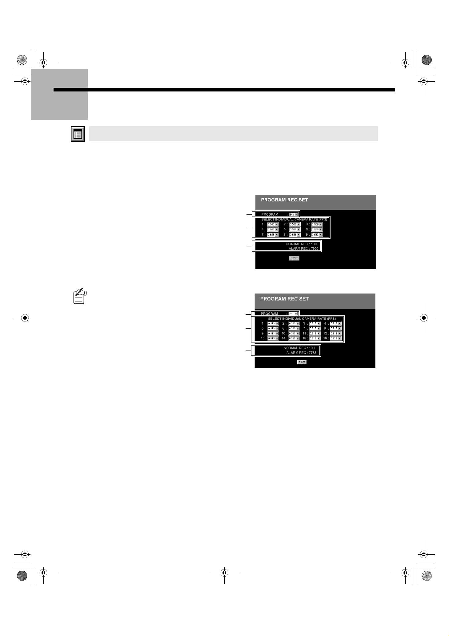
3. PROGRAM REC SET
When more than one camera is connected to the digital video recorder, the camera rate (unique rec rate
for each camera) can be set separately for each camera. In addition, you can make up to four programs
that include settings such as the method of combining the images from each recording camera and
individual camera rates. You can specify the appropriate program when making [TIMER SET] and
[RECORDING MODE SET] menu settings.
1
Use the menu (1111) to specify a program number.
P-1 to P-4
2
Use the menu (2222) to specify the cameras that are
to be used for recording from the numbers of the
connected cameras that are being displayed on the
screen (DSR-3009 model: 1-9; DSR-3016 model: 1-
16), and set the camera rate for each camera
selected.
• If a camera is not to be recorded: Select “OFF”.
• If a camera is to be recorded: Set the camera rate.
Default setting DSR-3009 model: 0.556 FPS
DSR-3016 model: 0.313 FPS
1
2
3
Screen example for DSR-3009 model
The camera rate values that appear in the menu lists
will vary depending on the number of channels
connected. The maximum value for REC RATE in
PROGRAM REC mode is 30 fps, so the values in the
table will be this maximum value divided by the
number of channels, and comprises the upper limit
for the setting.
3
Click [SAVE] to complete the setting.
When the setting is completed, the available time for normal
recording and the number of alarm recordings that are
possible under the conditions that have been set will be
displayed for reference (3).
4
You can repeat the above procedure to program up
to a maximum of four different patterns.
1
2
3
Screen example for DSR-3016 model
English
9
Page 11
L8HBA_US(DSR-3016 NETWORK)(GB only).book 10 ページ 2003年3月28日 金曜日 午後6時44分
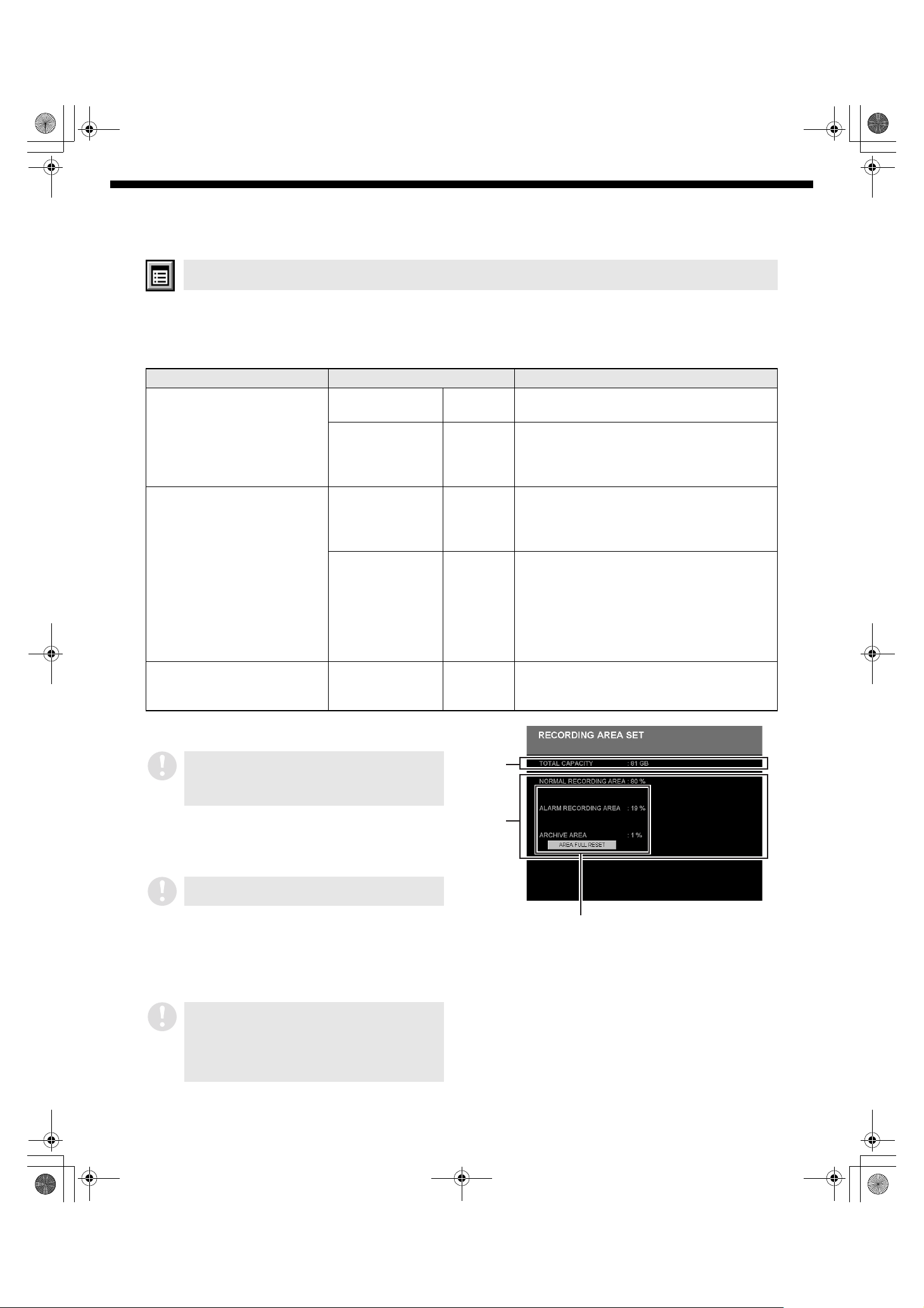
4. RECORDING AREA SET
The hard disk in this unit consists of three independent recording areas, each of which has five recording
modes.
A percentage of the total recording capacity is allocated to each recording area (settings are in units of
1%).
Recording area Recording mode Notes
NORMAL RECORDING
AREA
ALARM RECORDING AREA Alarm recording Automatic Recording is carried out automatically when
ARCHIVE AREA Copy Manual Copies and saves essential recordings from
1 Total capacity display
Displays the total capacity of the hard disk.
Normal recording Manual Recording is carried out manually using the
O button.
Timer recording Automatic Recording is carried out automatically within
the time range specified by the timer
recording setting made using the menu
screen.
an alarm is detected according to the alarm
recording settings made using the menu
screen.
Pre-alarm
recording
Automatic Images that are around the time that the
alarm was detected are recorded
automatically according to the pre-alarm
recording settings made using the menu
screen.
This is used as a complementary function to
alarm recording.
another recording area by using the
button on the operating panel manually.
Menu Setting Procedures
M
If two hard disks have been installed and the digital
video recorder’s HDD SET function has been used
to set mirroring to “ON”, the details for the disk with
the smaller capacity will be displayed.
2 Capacity display for each recording area
The recording capacity of each recording area of the digital
video recorder’s hard drive is displayed as a percentage of
the total capacity.
The capacities of the recording areas cannot be set
and changed from a connected computer.
3 Recording area reset
If the OVERWRITE setting is “OFF”, recording will stop
automatically when a recording area becomes full. If when
[AREA FULL RESET] has been selected, the recordings that
have been made will be deleted and recording will begin
again from the start of the recording area.
If the recording capacity for the normal recording
area and the alarm recording area have been set to
0% and if the OVERWRITE setting is “OFF”, there is
no need to use the reset function, and so the AREA
FULL RESET button will not appear on the screen at
such times.
1
2
3
10
English
Page 12
L8HBA_US(DSR-3016 NETWORK)(GB only).book 11 ページ 2003年3月28日 金曜日 午後6時44分
Menu Setting Procedures
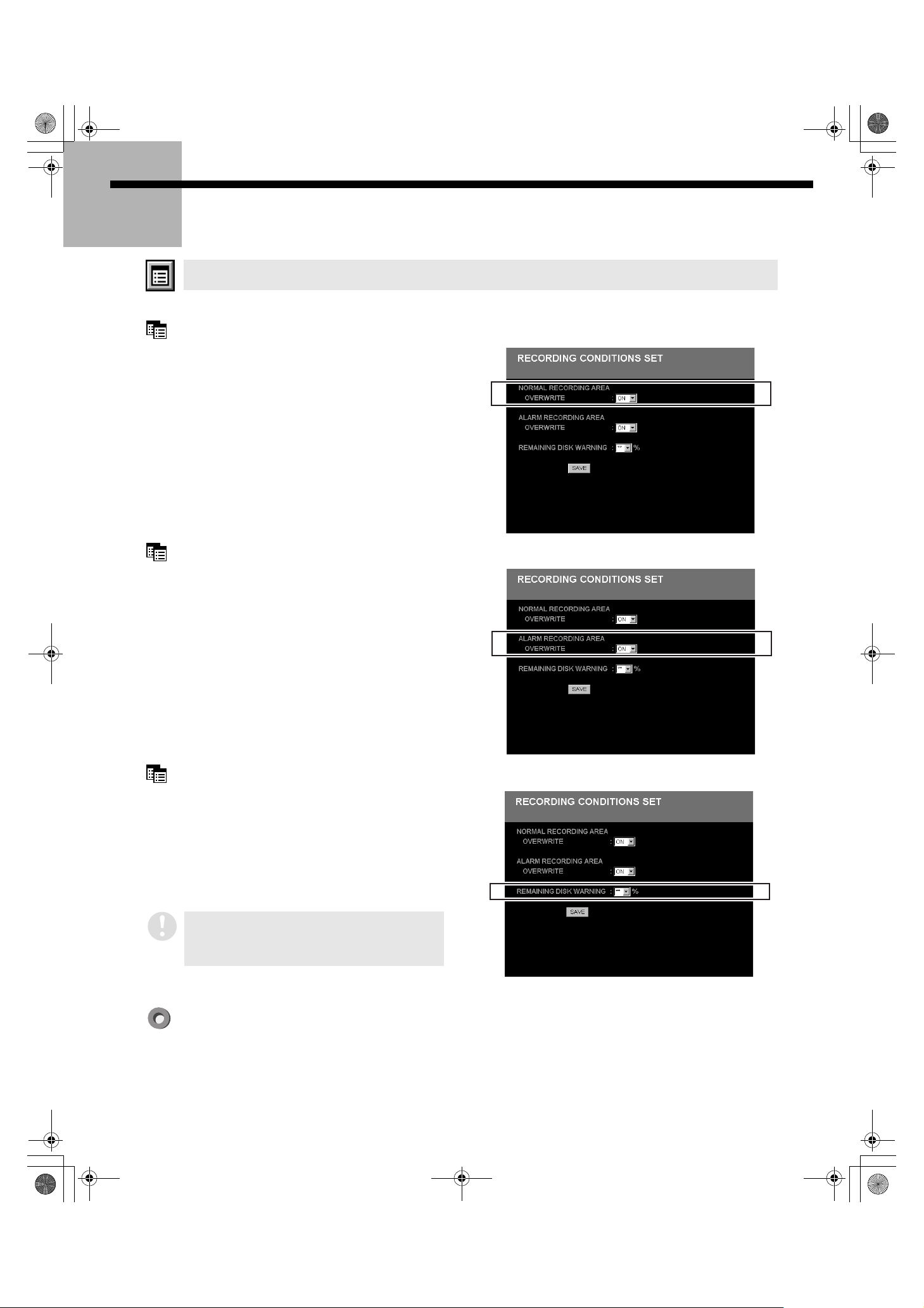
5. RECORDING CONDITIONS SET
This sets the overwrite conditions and remaining disk capacity warning criteria for each recording area.
NORMAL RECORDING AREA OVERWRITE (Default setting: ON)
This specifies whether to stop recording or to continue
recording by overwriting images that are currently
recorded on the hard disk when the normal recording
area has become full.
1
Select [ON/OFF] from the menu.
• ON: When the normal recording area becomes full,
• OFF: Recording will stop when the normal recording area
images will begin to be overwritten automatically
from the start of the normal recording area.
becomes full.
ALARM RECORDING AREA OVERWRITE (Default setting: ON)
This specifies whether to stop recording or to continue
recording by overwriting images that are currently
recorded on the hard disk when the alarm recording
area has become full.
1
Select [ON/OFF] from the menu.
• ON: When the alarm recording area becomes full,
images will begin to be overwritten automatically
from the start of the alarm recording area.
• OFF: Recording will stop when the alarm recording area
becomes full.
REMAINING DISK WARNING
The buzzer can be set to sound a warning if the
NORMAL RECORDING AREA OVERWRITE and ALARM
RECORDING AREA OVERWRITE settings are “OFF”
and the remaining disk capacity becomes low (see p.
25). The remaining disk area value at which a warning
will be given can be specified here.
1
Set the remaining disk area value from the menu.
Setting range: 1% to 10% (1% units)
If the OVERWRITE setting is “ON” for both
recording areas, no remaining area warning is
necessary, and so “**” is displayed and REMAINING
DISK WARNING cannot be set.
English
Click [SAVE] to complete the sub-menu settings (or changes).
11
Page 13
L8HBA_US(DSR-3016 NETWORK)(GB only).book 12 ページ 2003年3月28日 金曜日 午後6時44分
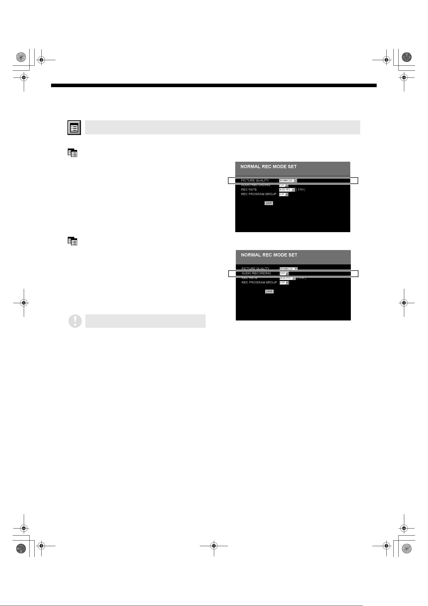
6. NORMAL REC MODE SET
This specifies the recording conditions for normal recording and timer recording.
PICTURE QUALITY (Default setting: ENHANCED)
This sets picture quality for normal recording.
1
Select a picture quality mode from the menu.
• BASIC (basic quality)
• NORMAL (normal quality)
• ENHANCED (enhanced quality)
• FINE (high quality)
• SUPER FINE (very high quality)
Menu Setting Procedures
AUDIO RECORDING (Default setting: OFF)
Sound can also be recorded in the normal recording
area at the same time as images are recorded.
However, when sound is recorded, the recording
capacity of the normal recording area will be reduced
because the audio data is also recorded in the normal
recording area.
1
Select [ON/OFF] from the menu.
• ON: Sound is recorded.
• OFF: Sound is not recorded.
Audio recording can be set when the REC RATE
setting is between 10 and 60 FPS.
12
English
Page 14
L8HBA_US(DSR-3016 NETWORK)(GB only).book 13 ページ 2003年3月28日 金曜日 午後6時44分
Menu Setting Procedures
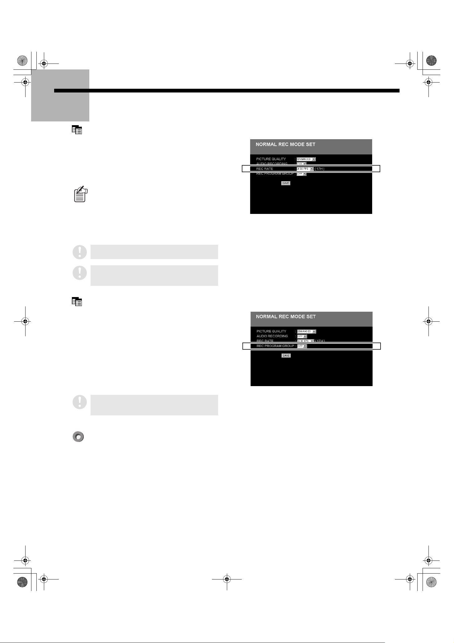
REC RATE (Default setting: A 30 FPS)
This sets the recording rate for normal recording.
1
Select the recording cycle for normal recording
from the menu.
A 60, A 30, A 20, A 15, A 10, 7.5, 6, 5, 4.286, 3.75, 3.333, 3,
2.727, 2.308, 2, 1.667, 1.429, 1.25, 1.111, 1, 0.5, 0.333, 0.25,
0.2, 0.1, 0.05, 0.033 (Units: FPS)
The image resolution is determined by image quality
× REC RATE. The higher the image quality and the
faster the REC RATE setting, the higher is the image
resolution. However, higher image resolutions also
consume disk space more quickly, and so the total
recording time available will be reduced. You should
adjust the value as required while considering these
factors.
If pre-alarm recording is set to “ON”, the REC RATE
will be limited to A 15 FPS.
The REC RATE during timer recording should be
set separately using the [TIMER SET] menu. (See p.
14)
REC PROGRAM GROUP (Default setting: OFF)
This sets the camera images to be recorded during
normal recording.
1
Select the camera images to be recorded during
normal recording from the menu. (See p. 9)
OFF: No program group is specified and all camera images
are recorded.
P-1: Specifies program No. 1.
P-2: Specifies program No. 2.
P-3: Specifies program No. 3.
P-4: Specifies program No. 4.
The [REC PROGRAM GROUP] for timer recording
should be set separately using the [TIMER SET]
menu. (See p. 14)
English
Click [SAVE] to complete the settings (or changes) for the sub-menu that is displayed on the screen. The
available time for recording under the conditions that have been set will be displayed in parentheses for
reference.
13
Page 15

L8HBA_US(DSR-3016 NETWORK)(GB only).book 14 ページ 2003年3月28日 金曜日 午後6時44分
7. TIMER SET
This lets you set the conditions for timer recording, such as the timer operating time, separately for each
day of the week.
1
Select the timer recording conditions for each weekday from the menu.
2
Click [SAVE] to complete the timer settings (or changes).
1 2 3 4 5 6
Menu Setting Procedures
7
1 WEEK
Specifies the weekdays for making timer recordings. Several
timer recordings can also be made at different times on the
same weekday by changing the setting row.
2 START
Enter the time for timer recording to start.
3 STOP
Enter the time for timer recording to stop.
4 PROGRAM (Default setting: OFF)
Specify the program to use for recording images. (See p. 9)
The [TIMER SET] menu is for setting the conditions for timer recording. To actually carry out timer recording based on
these setting conditions, you will need to click the [TIMER] button on the operating panel. (See p. 6 and 22.)
When the digital video recorder switches to timer recording standby mode and the setting time is reached, timer
recording will start automatically.
The timer recording operation is indicated by a “TIMER STANDBY” or “TIMER RECORDING” message appearing on the
screen.
Points to note and applications of timer settings
• If timer reservations overlap, the earlier time setting will take precedence for recording.
• If you wish to set the timer to continue for more than 24 hours, use the bottom two lines on the setting screen to make this setting.
1. Switch the setting format by clicking the [OVER 24H] button.
2. Use the top line to set the start day and time.
3. Use the bottom line to specify the stop day and the time and recording cycle.
4. When [SET] in the bottom line is set to [ON], timer recording for more than 24 hours will be set.
5 FPS (Default setting: A30 FPS)
Set the recording rate (See p. 13)
6 SET (Default setting: OFF)
Set this to “ON” if timer recording is to be carried out.
Set this to “OFF” if timer recording is not to be carried out.
7 DLY
Enter the start and stop times, image recording program and
the recording rate and change SET to “ON” to enable timer
recording at the same time each day.
The DLY setting conditions take precedence over the setting
conditions that have been made separately for each day.
14
English
Page 16

L8HBA_US(DSR-3016 NETWORK)(GB only).book 15 ページ 2003年3月28日 金曜日 午後6時44分
Menu Setting Procedures
8. HOLIDAY SET
This menu is used to specify particular days as holidays. The timer recording operation on specified
holidays will be the same as that for Sundays.
A holiday setting can be made for days such as
national holidays and company holidays when the
same level of security as for Sundays is required.
1
Select the day to be specified as a holiday from the
menu. (Left side: month; right side: day)
Up to 20 days can be specified as holidays.
2
Click [SAVE] to complete the holiday settings (or
changes).
If the “DLY” function is specified on any line, then
recording will be carried out under those conditions
on Sundays also. The “DLY” setting has priority at
all times, even over Sunday settings.
9. ALARM REC MODE SET
This sets the recording conditions for alarm recording.
PICTURE QUALITY (Default setting: ENHANCED)
This sets the picture quality for alarm recording.
1
Select the picture quality from the menu.
• BASIC (basic quality)
• NORMAL (normal quality)
• ENHANCED (enhanced quality)
• FINE (high quality)
• SUPER FINE (very high quality)
AUDIO RECORDING (Default setting: OFF)
Sound can also be recorded in the alarm recording
area at the same time as images are recorded.
However, when sound is recorded, the recording
capacity of the alarm recording area will be reduced
because the audio data is also recorded in the alarm
recording area.
1
Select [ON/OFF] from the menu.
• ON: Sound is recorded.
• OFF: Sound is not recorded.
English
Audio recording can be set when the REC RATE
setting is between 10 and 60 FPS.
15
Page 17

L8HBA_US(DSR-3016 NETWORK)(GB only).book 16 ページ 2003年3月28日 金曜日 午後6時44分
ALARM RECORDING
This specifies whether alarm recording will be carried
out or not, and sets the recording cycle and recording
conditions when alarm recording is carried out.
1
Select an alarm recording mode from the [ALARM
RECORDING] menu (default setting: OFF).
• OFF: No alarm recording will be carried out.
• ENABLED:
Alarm recording is carried out at any time, without
regard to timer recording (timer settings).
• AL-REC ON TIMER:
Alarm recording is only carried out during timer
recording.
• AL-REC OFF TIMER:
Alarm recording is only carried out at times other
than during timer recording.
• OLY AL-RC ON TMR:
During the time set by the timer, the only recording
carried out is alarm recording, not timer recording.
Menu Setting Procedures
2
Select the alarm recording method from the
[ALARM INTERLEAVE] menu. (Default setting:
ONLY)
• ONLY: Only the camera where the alarm was triggered is
• SW: The images from the camera where the alarm was
3
Specify the program for recording camera images
recorded.
triggered and the images from the cameras
specified by the PROGRAM GROUP setting are
recorded alternately.
from the [PROGRAM GROUP] menu. (See p. 9)
OFF: No program group is specified and all camera images
are recorded.
P-1: Specifies program No. 1.
P-2: Specifies program No. 2.
P-3: Specifies program No. 3.
P-4: Specifies program No. 4.
(Default setting: OFF)
4
Select the recording cycle from the [REC RATE]
menu.
A 60, A 30, A 20, A 15, A 10, 7.5, 6, 5, 4.286, 3.75, 3.333, 3,
2.727, 2.308, 2, 1.667, 1.429, 1.25, 1.111, 1, 0.5, 0.333, 0.25,
0.2, 0.1, 0.05, 0.033 (Units: FPS)
(Default setting: A 30 FPS)
5
Set the duration for alarm recording from the
[DURATION] menu.
5 SEC, 10 SEC, 20 SEC, 40 SEC, 1 MIN, 2 MIN, 3 MIN,
4 MIN, 5 MIN, 10 MIN, 15 MIN, CC, INDIV.
(Default setting: 5 SEC)
The alarm recording duration can be set separately
for each camera. If you select [INDIV.] from the
[DURATION] menu, alarm recording is then carried
out for each camera for the duration of time that has
been set using the [ALARM DURATION SET] menu
that is described later on. (See p. 18)
16
English
Page 18

L8HBA_US(DSR-3016 NETWORK)(GB only).book 17 ページ 2003年3月28日 金曜日 午後6時44分
Menu Setting Procedures
PRE-ALARM RECORDING
This specifies whether pre-alarm recording will be
carried out or not, and sets the recording conditions
when pre-alarm recording is carried out. (See p. 23)
1
Select “ON/OFF” from the [PRE-ALARM
RECORDING] menu.
• ON: Pre-alarm recording is carried out.
• OFF: Pre-alarm recording is not carried out.
When [ALARM RECORDING] is set to “OFF”, “**” is
displayed and pre-alarm setting cannot be carried
out.
2
Select the recording cycle from the [REC RATE]
menu.
A 60, A 30, A 20, A 15, A 10, 7.5, 6, 5, 4.286, 3.75, 3.333, 3,
2.727, 2.308, 2, 1.667, 1.429, 1.25, 1.111, 1 (Units: FPS)
(Default setting: A 15 FPS)
A 60 FPS can only be selected when the NORMAL
REC AREA capacity setting is 0%.
3
Select the pre-alarm recording duration from the
[DURATION] menu.
2 SEC, 3 SEC, 5 SEC, 10 SEC, 20 SEC, 40 SEC, 1 MIN,
2 MIN, 3 MIN, 4 MIN, 5 MIN, 10 MIN, 15 MIN
(Default setting: 1 MIN)
ALARM TRIGGER (Default setting: ALARM)
This sets an alarm trigger (a signal for alarm recording
to begin) that will become the condition for the
operation of alarm recording.
1
Select an alarm recording starting signal from the
menu.
• ALARM: Alarm recording starts when an external alarm
• SENSOR: Alarm recording starts when a motion sensor
• ALARM AND SENSOR:
• ALARM OR SENSOR:
reacts.
reacts.
Alarm recording starts when an external alarm
and motion sensor both react at the same time.
Alarm recording starts when either an external
alarm or a motion sensor react.
English
External alarm detection: This is when external sensor information (such as the opening or closing of a door switch) is
input to the digital video recorder’s alarm input terminals while the digital video recorder is online.
Motion sensor detection: This is when the motion sensor settings cause movement to be detected on the monitor screen.
Click [SAVE] to complete the settings (or changes) for the sub-menu that is displayed on the screen. The
number of alarm recordings available under the conditions that have been set will be displayed in parentheses
for reference.
17
Page 19

L8HBA_US(DSR-3016 NETWORK)(GB only).book 18 ページ 2003年3月28日 金曜日 午後6時44分
10. ALARM DURATION SET
The duration of alarm recording can be set separately for each camera. The DURATION setting for each
camera that is made using the [ALARM DURATION SET] menu is effective when [DURATION] in the
[ALARM RECORDING] menu is set to “INDIV.” (See p. 16)
1
Select the alarm recording duration for each
camera from the menu.
5 SEC, 10 SEC, 20 SEC, 40 SEC, 1 MIN, 2 MIN, 3 MIN,
4 MIN, 5 MIN, 10 MIN, 15 MIN, CC
(Default setting: 5 SEC)
2
Click [SAVE] to set (or change) the alarm recording
durations for each camera.
Menu Setting Procedures
Screen example for DSR-3009 model
Screen example for DSR-3016 model
11. DISPLAY SET
This specifies the information to be displayed on the monitor by selecting “ON” or “OFF” in the menu.
Because this setting specifies the information to be displayed on the monitor that is connected to the main unit, it will
have no effect on the computer screen.
DATE (Default setting: ON)
Current date or recording date
TIME (Default setting: ON)
Current time or recording time
ALARM TYPE (Default setting: ON)
Type of alarm recording
For alarm recording: “ALARM” is displayed.
For pre-alarm recording: “PRE” is displayed.
QUALITY (Default setting: ON)
Quality of images being recorded or played back
AUDIO (Default setting: ON)
The audio recording display during recording and
playback.
ALARM COUNT (Default setting: ON)
Cumulative number of alarms
The maximum count that can be displayed is 9999. If the count
exceeds this number, it will be reset to 0.
Click [SAVE] to complete the DISPLAY SET menu settings (or changes) that are displayed on the screen.
18
English
Page 20

L8HBA_US(DSR-3016 NETWORK)(GB only).book 19 ページ 2003年3月28日 金曜日 午後6時44分
Menu Setting Procedures
12. RS-232C/RS-485 SET
This displays information related to the digital video recorder’s interface.
This menu only lets you check the settings; it
cannot be used to change the settings.
CONTROL
This shows the type of interface being used to control
the digital video recorder.
• RS-232C: Control by RS-232C
• RS-485: Control by RS-485
DATA SPEED
This shows the RS-232C or RS-485 communication
speed.
• 2400/4800/9600/19200(bps)
ALARM INFO
For RS-485 communication, this specifies whether
alarm information is to be transmitted or not.
• ON: Alarm information is to be transmitted.
• OFF: Alarm information is not to be transmitted.
ADDRESS
This shows the address when RS-485 has been
selected.
• Valid settings range from 0 to 127.
STATUS INFO
For RS-485 communication, this specifies whether
status information is to be transmitted or not.
• ON: Status information is to be transmitted.
• OFF: Status information is not to be transmitted.
13. BUZZER SET
This enables the warning buzzer to sound as necessary. Select “ON” or “OFF” for the menu item settings.
These settings only cause a buzzer to sound at the digital video recorder. They do not cause a buzzer to sound at the
computer.
ALARM (Default setting: OFF)
This causes the buzzer to sound when there is an
alarm.
DISK FULL (Default setting: ON)
This causes the buzzer to sound a warning when the
free space remaining in the hard disk recording reach a
preset value. (See p. 11)
KEY IN (Default setting: OFF)
This causes the buzzer to sound a key operation beep
when an operating button is pressed.
NON REC (Default setting: OFF)
This causes the buzzer to sound a warning when
recording stops.
DISK ERROR (Default setting: ON)
This causes the buzzer to sound a warning if a hard
disk error has occurred.
LOCK WARNING (Default setting: ON)
This causes the buzzer to sound a warning if an
unauthorized operating button is pressed when the
security lock is on.
The buzzer sounds twice during a 0.5-second cycle.
Click [SAVE] to complete the BUZZER menu settings (or changes) that are displayed on the screen.
English
19
Page 21

L8HBA_US(DSR-3016 NETWORK)(GB only).book 20 ページ 2003年3月28日 金曜日 午後6時44分
14. NETWORK SET
When the digital video recorder is connected to a network, NETWORK SET is used to make settings
beforehand from the main unit, but the settings that have been specified from the main unit can also be
changed from the computer.
However, when network settings are changed, the digital video recorder will be momentarily
disconnected from the network and control wills witch to the digital video recorder, so the network
settings will need to be changed as necessary at the computer also. (See p. 3)
IP ADDRESS (1)
This enables the IP address for the digital video
recorder to be reset.
SUBNET MASK (2)
This enables the subnet mask for the digital video
recorder to be reset.
2
4
1
3
Menu Setting Procedures
GATE WAY (3)
This enables the gateway for the digital video recorder
to be reset.
PORT (4)
This enables the port number for the digital video
recorder to be reset.
The setting range is from 1 to 65535 (Default setting: 80).
If the port is set to a value other than the default
value of “80”, add a “:” followed by the port number
to the end of the IP address when typing in the URL.
Example of URL if the port is set to “81”
http://192.168.0.1:81/
PASSWORD SETTING (5)
This enables the passwords for each user level to be
reset. (See p. 4)
User level 123
User name ID1 ID2 ID3
Available
menus
Password (Default value) 1111 2222 3333
The password can consist of 4 to 8 alphanumeric characters.
Monitoring live images mmm
Monitoring and
searching for recorded
images
Starting and stopping
recording, timer
recording, changing
main unit settings, etc.
mm
m
5
6
NETWORK SPEED (6)
This enables the network speed to be reset.
NO LIMIT/64/128/256/512/1024 (kbps)
When reset from the main unit, the default setting (NO LIMIT) is
restored.
Click [SAVE] to complete the NETWORK menu settings (or changes) that are displayed on the screen.
20
English
Page 22

L8HBA_US(DSR-3016 NETWORK)(GB only).book 21 ページ 2003年3月28日 金曜日 午後6時44分
Menu Setting Procedures
15. HDD SET
This displays hard disk information. In addition, if another hard disk has been added and mirroring
recording by the digital video recorder has been set to “ON”, you can also set the drive to be given
priority for the reading of data.
PLAYBACK DRIVE
If mirroring recording by the digital video recorder has
been set to “ON”, you can select the disk drive from
which the recorded data is to be read from menu (3333).
If these settings are made after an extra hard disk
has been installed, the hard disks will be in the
initialized condition with all recorded images
erased. Any important recorded images should be
stored on a computer.
1
2
3
What is mirroring?
Mirroring recording is the term used to refer to
recording the same images on two hard disks
when an extra hard disk has been added.
Turning on mirroring is a backup option so
that if the data recorded on one disk becomes
corrupted for some reason, the data from the
other disk that was recorded correctly can be
retrieved instead.
1
Select “Disk 1” or “Disk 2” from the menu.
• DISK 1: Data will be read from Disk 1.
• DISK 2: Data will be read from Disk 2.
2
Click [SAVE] to complete the PLAYBACK DRIVE
menu settings.
Hard disk capacity
1
Displays the total capacity of the hard disk.
If an extra hard disk has been added, the capacities of each
hard disk are shown separately.
MIRRORING
2
This shows the mirroring recording setting for the digital video
recorder.
• ON: Mirroring recording is carried out.
• OFF: Mirroring recording is not carried out.
PLAYBACK DRIVE
3
16. POWER FAILURE/USED TIME
This displays the number of power failures and period of time that the digital video recorder has been
used for recording.
1 POWER FAILURE
This shows the number of power failures, the date and time of
occurrence, and the date and time of recovery.
2 USED TIME
This shows the period of usage of this unit.
• DISK1 USE: Total recording time for Disk 1
• DISK2 USE: Total recording time for Disk 2
• POWER: Total time the unit has been switched on
3 FIRMWARE
This shows the firmware version.
1
2
3
English
21
Page 23

L8HBA_US(DSR-3016 NETWORK)(GB only).book 22 ページ 2003年3月28日 金曜日 午後6時44分
Recording Images
This digital video recorder can record images being monitored and alarm on the internal hard disk by the
methods specified below.
In order to record images, the necessary menu settings should be made beforehand in accordance with
the installation environment. (See p. 7)
■■■■ Normal recording
This is a manual operation for recording live images that are currently
being viewed into the normal recording area.
1
Click the O button on the operating panel to start normal recording.
2
Click the P button on the operating panel to stop normal recording.
If more than one camera is connected to the digital video recorder for
monitoring, the images for all cameras that have been set in the REC
CAMERA GROUP specified by the NORMAL REC MODE SET setting will be
recorded, regardless of the number of live image display screens. (See p.
13)
■■■■ Timer recording
This is for automatically recording an image that is being viewed into the
normal recording area at a specified time.
Timer recording is not possible during normal recording.
1
The conditions for timer recording (day of the week, time, recording
speed, etc.) are set beforehand using the TIMER SET menu screen.
(See p. 14)
2
Timer recording is started by clicking the Q button on the operating
panel and recording will start and stop automatically in accordance
with the specified times. The timer recording operation is indicated by
a “TIMER STANDBY” or “TIMER RECORDING” message appearing on
the screen.
If “OLY AL-RC ON TMR” has been selected as the ALARM RECORDING
setting (see p. 16), timer recording standby operation using the Q button
is not possible.
3
To cancel timer recording, click the Q button on the operating panel
again when in timer recording standby mode.
The display example is that for the
DSR-3016 model.
22
English
Page 24

L8HBA_US(DSR-3016 NETWORK)(GB only).book 23 ページ 2003年3月28日 金曜日 午後6時44分
Recording Images
■■■■ Alarm recording
Alarm images are recorded automatically in the alarm recording area when
the alarm input terminals or motion sensor have detected an alarm.
When alarm recording is in operation, normal recording, timer recording
and pre-alarm recording are automatically suspended, and they are
resumed when the alarm recording is finished.
You can set the computer to play back a sound file that is stored in a
specified folder on the computer's hard disk while alarm recording is in
progress, to give the computer its own original warning sound to be played
in the event of an alarm.
1. Create the warning sound (WAV file).
2. Rename the file and save it as follows.
"C:\BUZZER\BUZZER.WAV"
To stop the warning sound from playing while an alarm is being recorded,
click the P button on the operating panel.
1
The conditions for alarm recording are set beforehand using ALARM
REC MODE SET menu screen. (See p. 15)
2
Alarm recording begins automatically when an alarm is detected,
regardless of the operating or working conditions of the digital video
recorder.
3
Alarm recording stops automatically after the amount of time specified
by the DURATION setting has elapsed.
■■■■ Pre-alarm recording
When pre-alarm recording has been set beforehand, the same images will
be recorded normally in the normal recording area and also in the alarm
recording area. The normal recording images will be recorded in this way
for the length of time specified by the DURATION setting, so that the
images recorded before the alarm occurred can also be seen when the
alarm recording is played back.
1
Set the pre-alarm recording conditions using the [PRE-ALARM
RECORDING] menu in the ALARM REC MODE SET menu screen. (See
p. 17)
2
The most recent images will be recorded automatically for the
specified duration, and they will be updated by being overwritten.
3
When an alarm recording is being carried out, pre-alarm recording is
automatically suspended, and it is resumed when the alarm recording
is finished.
English
23
Page 25

L8HBA_US(DSR-3016 NETWORK)(GB only).book 24 ページ 2003年3月28日 金曜日 午後6時44分
Viewing Images
Live images or recorded images can be viewed at any time when required.
Operations such as switching between live images and recorded images that are being played back and
changing the display screen do not have any effect on other operations such as timer recording and
alarm recording.
■■■■ Viewing Live Images
Click the G button on the operating panel to stop playback. The display will then change to viewing live images.
■■■■ Playing Back Recorded Images
You can play back images either by specifying the images to be played back or without specifying images.
Specifying images Playback method
When not specifying
images
When specifying
images
Click the H button on the operating panel. The screen will change to the playback
mode screen, and playback of images in the normal recording area and the alarm
recording area will be carried out in the order that they were recorded.
• If playing back recorded images for the first time after being recorded, or if the digital
video recorder has been reset, playback will start from the first image recorded.
• When playing back images for the second and subsequent time, playback will start
from the point where the previous playback session ended.
You can use the search function to search for the images that you would like to play
back from all images that have been recorded in all of the different areas of the hard
disk.
When you search for images to be played back in search mode and then select an
image, the display will changes automatically to the playback mode screen and the
selected images will be played back. Refer to “Search Mode” in the next section for
further details.
The screen display may become momentarily unstable or playback may appear to pause when the following operations
are carried out, but this is normal and is not the sign of a malfunction.
• When playback is carried out continuously between the normal recording area and the alarm recording area, the images
may flicker momentarily when switching between the two areas.
• If you use normal playback or fast-forward and rewind playback during alarm recording or during continuous playback
between the normal recording area and alarm recording area, the images may appear to freeze at times.
24
English
Page 26

L8HBA_US(DSR-3016 NETWORK)(GB only).book 25 ページ 2003年3月28日 金曜日 午後6時44分
Viewing Images
■■■■ Specifying the Number of Display
Screens (1111)
If more than one camera is connected to the digital video recorder, multiple
camera images can be displayed on the screen in a multi-screen format. To
do this, you need to specify the channel numbers for the monitoring
cameras that are to be displayed on the monitor screen.
m Viewing images in a single-screen display
Click the [CHANNEL SELECT] button on the operating panel and select a single
channel for viewing. Images from the selected channel will appear on the screen as a
single-screen display.
The channel number selected will appear in the [CHANNEL] box.
• DSR-3009 model: 9 channels
• DSR-3016 model: 16 channels
m Viewing images in a 9-screen or 16-screen multi-screen display
Click the button on the operating panel. All camera images from the cameras that
are being monitored or that have been registered will appear on the screen in a 16screen or 9-screen multi-screen display. In the case of 16-channel screens, the display
will alternate between a 9-screen display and a 16-screen display each time you click
the button.
• DSR-3009 model: 9-screen display
• DSR-3016 model: 16-screen display
m Viewing images in a 4-screen multi-screen display
Click the button on the operating panel. The camera images from the cameras
that are being monitored or that have been registered will appear on the screen in a 4screen multi-screen display. Each time you click the button, the 4-screen multiscreen changes to show channel numbers 1-4, 5-8, 9-12 and 13-16 respectively.
m Changing the on-screen display position
Click the button on the operating panel to change the display position on the
monitor for information such as the date and time.
Top-right Bottom-right Not displayed
1
2
The display example is that for
the DSR-3016 model.
■■■■ Playback Mode Operations (2222)
m For playback
Click the H button on the operating panel.
m To adjust the playback speed
The playback speed can be increased or decreased in steps by pressing the E or
D buttons on the operating panel during playback.
m For reverse playback
Click the F button on the operating panel.
This operation is possible even when the images are paused.
m To adjust the reverse playback speed
The reverse playback speed can be increased or decreased in steps by pressing the
E or D buttons on the operating panel during reverse playback.
m To still playback
Click the J button on the operating panel during playback to pause playback.
Click the J button again while playback is paused to return to normal playback
mode.
m For frame feed (forward/reverse)
Stilled playback images can be advanced (or reversed) one frame at a time by clicking
the K button (or the I button) on the operating panel while playback is paused.
m For alarm skip
Skip to the next (or previous) alarm event by pressing the B button (or the C
button) on the operating panel during playback.
English
25
Page 27

L8HBA_US(DSR-3016 NETWORK)(GB only).book 26 ページ 2003年3月28日 金曜日 午後6時44分
■■■■ Image Adjustment and Audio Playback
The display image can be adjusted and audio can be played back using the following adjustments.
Select the adjustment values from the menus, and then click [SET].
1
5 6
7
1
5 6
Viewing Images
7
Live mode screen Playback mode screen
READ INTERVAL (Default setting: 1)
1
Five stages of image display speed can be selected.
The larger the setting value, the faster is the display speed.
However, the actual refresh speed is limited by the
communication speed of the network.
This setting is not available when AUDIO is set to ON.
SIZE (Default setting: 1)
2
The image size can be set to one of six sizes.
The larger the setting value, the larger is the display screen.
1: 320 × 240
2: 400 × 300
3: 640 × 480
4: 800 × 600
5: 1024 × 768
6: 1280 × 960
QUALITY (Default setting: 2)
3
The image quality can be set to one of three levels.
1:Lowest quality
2:Medium quality
3:Highest quality
8
9
3
4
2
8
G
F
3
4
2
4 AUDIO (Default setting: OFF)
This lets you set whether sound is played back or not at the
same time as images are displayed.
• OFF: Sound is not played back.
• ON-5SEC - 30SEC: Sound is played back
(The audio delay time is set at the
same time. If the network speed is
slow, set the audio delay time to a
longer period to prevent the sound
from dropping out.)
• The operating privileges must be set to a user
level of ID2 or higher for sound playback. If the
operating privileges are set to ID1, the sound
playback menu will not be displayed.
• In order to play back sound, install Active X on a
PC and set sound recording to "ON". (See p3, 12)
• Sound is given priority during playback, so the
images may not appear in some environments.
26
English
Page 28

L8HBA_US(DSR-3016 NETWORK)(GB only).book 27 ページ 2003年3月28日 金曜日 午後6時44分
Viewing Images
■■■■ On-screen Display Items
Image mode
5
LIVE: Indicates live mode.
PLAY: Indicates playback mode.
Time
6
LIVE MODE: Shows the current date and time.
PLAY MODE: Shows the recording date and time.
NORMAL RECORDING MODE
7
The current normal recording mode is shown for reference.
• STOP
• RECORDING
• TIMER STANDBY
• TIMER RECORDING
• AREA FULL (when there is no free space in the alarm
recording area)
ALARM RECORDING MODE
8
This shows the current alarm recording mode.
• STOP
• PRE-ALARM RECORDING
• ALARM RECORDING
• AREA FULL (when there is no free space in the alarm
recording area)
Users connected
9
If more than one user is connected, this shows the number of
users connected for each user level.
(Display example) ID1:3 ID2:1 ID3:0
The ID for the user who is at the location where this screen is
being viewed is displayed in red.
PLAYBACK AREA (playback mode screen only)
F
This indicates the recording area where the images currently
being played back are recorded.
• ALARM
• PRE-ALARM
• NORMAL
• ARCHIVE
SPEED (playback mode screen only)
G
This indicates the speed and direction of playback.
Display
PLAY Forward Normal
STILL Paused Paused
R.PLAY Reverse Normal
CUE Forward Fast forward
REV Reverse Fast reverse
SLOW Forward Slow forward
R.SLOW Reverse Slow reverse
Playback direction
Playback direction Playback speed
Playback directionPlayback direction
Playback speed
Playback speedPlayback speed
English
27
Page 29

L8HBA_US(DSR-3016 NETWORK)(GB only).book 28 ページ 2003年3月28日 金曜日 午後6時44分
Search
Five search modes are provided for different recording areas and image search patterns. These let you
quickly search for images and play them back.
■■■■ Basic Search Operations
Click the L button on the operating panel in live mode (when playback is stopped) to display the [SEARCH]
1
menu.
If you click the L button during playback mode, the message “Mode Error” will be displayed.
2
Click to select the required search mode in the [SEARCH] menu screen.
The specified search mode screen will be displayed.
3
Search for images by using the search mode screen.
Refer to the following pages for details on the search procedures.
4
Check the search images in the preview or thumbnail screens, and then click the screen.
The mode will change to playback mode and playback will start in single-screen display.
Operations such as pausing and fast-forwarding are exactly the same as for normal playback. (See p. 25)
■■■■ Search Menus
Search Mode Search target recording area Notes
1 ALARM SEARCH ALARM RECORDING AREA Searches for alarm images from the
alarm event list and plays them back.
2 ALARM THUMBNAIL SEARCH ALARM RECORDING AREA Searches for alarm images by means
of thumbnails and plays them back.
3 TIME/DATE SEARCH NORMAL RECORDING AREA
ALARM RECORDING AREA
4 ARCHIVE AREA SEARCH ARCHIVE AREA Searches for images that have been
5 MOTION DETECTION
SEARCH
If the normal recording area is 0%, "ALARM SEARCH", "ALARM THUMBNAIL SEARCH" and "MOTION DETECTOR
SEARCH" cannot be selected.
NORMAL RECORDING AREA
ALARM RECORDING AREA
Searches for recorded images by date
and time and plays them back.
saved (copied) in the archive area from
the image list and plays them back.
Searches for recorded images in which
a motion sensor recorded movement,
and plays them back.
28
English
Page 30

L8HBA_US(DSR-3016 NETWORK)(GB only).book 29 ページ 2003年3月28日 金曜日 午後6時44分
Search Mode Operations
1. ALARM SEARCH
This displays a list of all alarm events recorded in the alarm recording area by alarm number.
Alarm images are searched for by alarm number and played back.
1
Select [ALARM SEARCH] from the [SEARCH]
menu.
A list of alarm events is displayed on the ALARM SEARCH
screen in order starting from the most recent recording date.
2
Select the number of the alarm image that you
wish to play back from the alarm event list, and
confirm the selection in the PREVIEW screen.
• When you click the alarm number in the list, the
corresponding alarm image will be displayed in the
PREVIEW screen.
• Up to eight alarm events can be shown on a single screen.
Click the [Back] or [Next] button to show the previous or
next eight events.
3
Once you have confirmed that the image to be
played back appears in the PREVIEW screen, click
the PREVIEW screen.
The images starting from the point that the alarm occurred will
be played back in a single-screen display.
1 42 3
NO: Alarm number
1
DATE/TIME: Date and time of recording
2
CH: Channel (camera number)
3
PREVIEW: Preview display of alarm image
4
2. ALARM THUMBNAIL SEARCH
This displays thumbnails of all alarm images recorded in the alarm recording area.
Alarm images are searched for and displayed from thumbnails.
1
Select [ALARM THUMBNAIL SEARCH] from the
[SEARCH] menu.
• The most recent alarm images are displayed with alarm
numbers on the ALARM THUMBNAIL SEARCH screen.
• Up to nine alarm events can be displayed as thumbnails on
a single screen. Click the [Back] or [Next] button to show
the nine previous or next thumbnail screens.
2
Click the thumbnail you wish to play back.
The images starting from the point that the alarm occurred will
be played back in a single-screen display.
English
29
Page 31

L8HBA_US(DSR-3016 NETWORK)(GB only).book 30 ページ 2003年3月28日 金曜日 午後6時44分
3. TIME/DATE SEARCH
Images in the normal recording and the alarm recording area can be specified by time and date and
played back.
1
Select [TIME/DATE SEARCH] from the [SEARCH]
menu.
The TIME/DATE SEARCH screen will appear.
2
Specify the channel (camera number) that you
wish to play back in the [CHANNEL] menu.
If the multiplexer function has not been used and only one
channel is available, [--] will be displayed.
3
Specify the recording time for the images that you
wish to play back in the [SEARCH] menu.
Year / Month / Day / Hours / Minutes
4
Click the [PREVIEW] button and confirm the image
specified in the PREVIEW screen.
After the search is complete, the image for the specified time
will be displayed.
1265
3
Search Mode Operations
If there is no image for the exact time and date
specified, the image closest to the specified time
and date will be displayed.
5
Once you have confirmed that the image to be
played back appears in the PREVIEW screen, click
the PREVIEW screen.
The images starting from the point that the alarm occurred will
be played back in a single-screen display.
4
RECORDING TOP: The oldest recorded image
1
RECORDING END: The newest recorded image
2
CHANNEL: Channel (camera number)
3
SEARCH: Date and time of recording for the image that
4
is to be played back
[PREVIEW]: Button for specifying preview
5
PREVIEW: Preview display of the image for the
6
specified date and time
4. ARCHIVE AREA SEARCH
This lets you play back images that have been saved (copied) in the archive area.
1
Select [ARCHIVE AREA SEARCH] from the
[SEARCH] menu.
A list of saved images is displayed on the ARCHIVE AREA
SEARCH screen in order starting from the earliest recording
date.
2
Select the number of the image that you wish to
play back from the list of saved images, and
confirm the selection in the PREVIEW screen.
• When you click the image number in the list, the
corresponding image will be displayed in the PREVIEW
screen.
• Up to eight saved images can be shown on a single
screen. Click the [Back] or [Next] button to show the
previous or next eight images.
3
Once you have confirmed that the image to be
played back appears in the PREVIEW screen, click
the PREVIEW screen.
The images starting from the point that the alarm occurred will
be played back in a single-screen display.
1 263
NO: Image number
1
DATE/TIME: Date and time of recording
2
CH: Channel (camera number)
3
CAPACITY TOTAL: Total capacity of the archive area
4
CAPACITY USED: Used capacity of the archive area
5
PREVIEW: Preview display of the archived image.
6
4
5
30
English
Page 32

L8HBA_US(DSR-3016 NETWORK)(GB only).book 31 ページ 2003年3月28日 金曜日 午後6時44分
Search Mode Operations
5. MOTION DETECTION SEARCH
If a motion sensor has been set to detect movement in a particular camera view, and images for that view
have been saved in the normal recording area or alarm recording area, you can search for those images
that have changed as a result of movement by an intruder, for example, and play back those images.
1
Select [MOTION DETECTION SEARCH] from the
[SEARCH] menu.
The MOTION DETECTION SEARCH screen will be
displayed.
2
Select the recording area to search for images
from the [SEARCH FROM] menu.
• ALARM: Only alarm recording area images will be
searched.
• NORMAL: Only normal recording area images will be
searched.
• ALARM AND NORMAL: Images in both the alarm
recording area and the normal recording area will be
searched.
3
Select the channel (camera number) to search for
images from the [MULTIPLEXER CHANNEL] menu.
If the multiplexer function has not been used and only one
channel is available, [--] will be displayed.
4
Click the [SET] button. The recording start and
recording end times for the images to be searched
will be displayed in the [START] and [END] menus
respectively. To refine the range over which to
search, use the menu to adjust the [START] or
[END] settings, and then click the [SET] button to
apply the changes.
The search results will be displayed in a message box.
5
Specify the motion sensor search conditions.
• Sensor position
The MOTION SENSOR SET screen will be displayed, and it
will be divided up into an 8 (H) × 10 (W) grid. Click the
position where you wish to set the focus for the motion
sensor. A red sensor setting mark will appear at that position.
(If you click a sensor position again, the sensor setting will be
canceled.)
• Sensor level
Select from the menu. The lower the number, the higher is
the sensitivity.
6
Click the [PREVIEW] button to confirm the image
in the PREVIEW screen.
Images in the specified time range in which the sensor has
detected movement will be searched and displayed on the
PREVIEW screen.
7
After confirming that the image found is the one
you wish to play back, click the PREVIEW screen.
The images starting from the point that the alarm occurred will
be played back in a single-screen display.
1
2
3
5
SEARCH FROM
1
This selects the recording areas to search in.
MULTIPLEXER CHANNEL
2
Channel (camera number) for images to be searched
START/END
3
This selects the recording start and end times for the images
to be searched.
SET
4
This sets the search conditions.
MESSAGE BOX
5
This shows the search results for images that satisfy the
search conditions.
• SEARCHING: Searching for images.
• FOUND: Images satisfying the search conditions have
been found.
• IMAGES NOT FOUND: No images that satisfy the search
conditions were found.
MOTION SENSOR SET
6
Motion sensor setting screen
MOTION SENSOR LEVEL
7
Sets the sensor sensitivity.
(OFF, 1 to 10)
PREVIEW
8
Search image preview display.
4
6
7
8
English
31
Page 33

L8HBA_US(DSR-3016 NETWORK)(GB only).book 32 ページ 2003年3月28日 金曜日 午後6時44分
Saving Recorded Images and Sound
Recorded images can be copied into the archive area of the hard disk or downloaded to a personal
computer.
This function is used only for saving important images that have been recorded in the normal recording
area and alarm recording area.
• Images that are copied will be saved as individual images. Moving pictures are handled by specifying the number of
images that need to be copied after the start picture. The maximum number of images that can be archived in one copy
operation is 10,000 when copying to the archive area and 1,000 when downloading to a computer.
• In order to protect the recording operation of the digital video recorder, the status of the network is checked, and if the
network is busy, the digital video recorder may be disconnected from the network depending on the operating
environment. If a command is given to transfer large volumes of data all at once (particularly when saving 100 or more
images at a time), the digital video recorder may be disconnected from the network, so you may need to restrict the
number of images being copied at one time depending on the environment.
• If the archive area becomes filled with images, you can temporarily copy the images to another medium such as a
CompactFlash card, and then press the [AREA FULL RESET] button on the RECORDING AREA SET main menu to reset
the digital video recorder. (See p. 10)
■■■■ COPY TO ARCHIVE AREA ON THE RECORDER
Play back the recorded images from the normal
1
recording area or alarm recording area, and pause
playback at the first image that is to be copied.
2
While playback is paused, click the M button on
the operating panel.
The COPY screen will be displayed.
3
Enter the number of images in the [HOW MANY]
box.
Enter the number of successive images to be copied after the
start image.
Valid range: 1 to 10000.
A warning message will be displayed if an invalid number is
entered.
4
Click the [START] button.
Copying to the archive area will begin and copying progress
will be displayed in the message box.
Copying in progress: COPYING TO ARCHIVE AREA !
Copying finished: COPY FINISHED !
1
3
4
Recording date and time: The date and time that the
1
images were recorded.
PLAYBACK AREA:
2
The recording area where the images being played back were
recorded.
• NORMAL
• ALARM
HOW MANY: The number of images being copied.
3
MESSAGE BOX: Shows the copying progress.
4
START: Click this button to start copying.
5
2
5
32
English
Page 34

L8HBA_US(DSR-3016 NETWORK)(GB only).book 33 ページ 2003年3月28日 金曜日 午後6時44分
Saving Recorded Images and Sound
■■■■ DOWNLOAD TO PC
Active X should be downloaded in advance.
(See p. 3, 12)
Recorded images and sound can be downloaded
to a computer.
1
Pause image playback at the image that will be the
starting point for downloading.
Play back recorded images and pause playback at the image
that will be the starting point for downloading.
1 2
All images recorded in the normal recording area,
the alarm recording area and the archive area can be
downloaded. However, the actual downloading
involves sending data from the archive area, so
when downloading images from the normal
recording area and the alarm recording area, they
are automatically saved temporarily in the archive
area.
2
While playback is paused, click the N button on
the operating panel.
The DOWNLOAD screen will be displayed.
3
Enter the number of images in the [HOW MANY]
box.
Enter the number of successive images to be copied after the
start image.
Valid range: 1 to 10000.
A warning message will be displayed if an invalid number is
entered.
Since the Internet Explorer displays a page only for
5 minutes, the number of pictures to download has
to be set accordingly, so that the download is
completed within 5 minutes.
4
Set the [AUDIO] button.
If downloading sound at the same time as the images, set the
[AUDIO] button to "ON". If you would only like to download
images, leave the [AUDIO] button at the default setting
("OFF").
3
4
Recording date and time: The date and time that the
1
images were recorded
PLAYBACK AREA:
2
The recording area where the images being played back were
recorded
• NORMAL
• ALARM
• ARCHIVE
HOW MANY: The number of images being copied.
3
MESSAGE BOX: Shows the copying progress.
4
START: Click this button to start downloading.
5
AUDIO: Sound downloading ON/OFF
6
5
6
English
5
Click the [START] button.
Downloading begins and [PLEASE WAIT !] is displayed in the
message box.
When downloading all pictures is finished, the display
changes to the Image Viewer screen and a data save
confirmation dialog is displayed.
6
Click the [OK] button in the confirmation dialog to start the saving operation.
• If saving images only
Select "Save As..." from the "File" menu in Internet Explorer, specify the saving location and file name in the "Save as Web Page" dialog
box, and then click [Save]. The web page will then be saved, and all of the images will be saved at the same time.
• If saving both images and sound
Click the [SAVE WITH AUDIO] button, specify the saving location and file name in the "SAVE WITH AUDIO" dialog box, and then click
[Save]. When the saving is complete, and the confirmation dialog box appears, click [OK].
• Please use Internet Explorer 5.0 or higher. Images cannot be saved with other versions.
• Downloading of sound data is limited to two minutes of data. If there are a large number of images to download, it may
not be possible to download the sound.
33
Page 35

L8HBA_US(DSR-3016 NETWORK)(GB only).book 34 ページ 2003年3月28日 金曜日 午後6時44分
Saving Recorded Images and Sound
* Image Viewer Screen
This enables downloaded images to be confirmed and saved.
45 6 7
3
2
1
8
9
F
G
Thumbnail images
1 TOP
This displays the first image.
2 PREV.
This displays the previous image.
3 R.PLAY
This plays back the images in reverse. When the first image is
reached, it returns to the last image and continues reverse
playback from that image.
4 STOP
This stops playback.
5 PLAY
This plays back the images. When the last image is reached,
it returns to the first image and continues playback from that
image.
6 NEXT
This displays the next image.
7 END
This displays the last image.
8 IMAGE SIZE
This sets the image display size.
1 400 × 300 4 1024 × 768
2 640 × 480 5 1280 × 960
3 800 × 600
H
I
J
K
9 PLAY SPEED
This sets the playback speed (cycle).
1 1000msec 4 100msec
2 500msec 5 25msec
3 250msec
* The above playback speed (cycle) value will vary
depending on the specifications of the computer.
F IMAGE NUMBER
This displays the number of the image being played back.
G PLAY AUDIO
To play back sound at the same time when playback
operations care carried out on the screen.
H CHANNEL
This shows the channel (camera number) for the images that
are being downloaded.
I TIME
This displays the recording date and time for the image being
played back.
J DOWNLOAD COUNT
The number of images being downloaded are displayed as
“Number of images downloaded / Total number of images”. (If
the number of images recorded does not reach the number of
images entered, the total number of images will equal the
number of images recorded.)
K SAVE WITH AUDIO
To save images and sound at the same time.
34
Buttons G and K are only displayed when
[AUDIO] is set to "ON" in the download window.
English
Page 36

L8HBA_US(DSR-3016 NETWORK)(GB only).book 35 ページ 2003年3月28日 金曜日 午後6時44分
DVR Viewer
The DVR Viewer is a program designed specifically for DVRs of all series. It can be used to play
back image and sound data that has been copied from a DVR onto media such as computer
hard disk drives, CompactFlash cards and CD-Rs.
The DVR Viewer can be downloaded from the Sanyo website at the URL given below.
Sanyo website URL: http://www.sanyosecurity.com
When playing back sound data, you will need Version 1.4 or later. In the case of data that has been copied from a DVR to
a CD-R, only the images can be played back.
■■■■ Operating environment
The following operating environment is required in order to use the DVR Viewer.
• Applicable operating system;Windows 98, 98SE, Me, 2000, XP
• Applicable computer:PC/AT compatible computer running one of the above operating systems
• When playing back images that include sound, you will need to have the Active X plug-in pre-installed on the system. (See p3)
■■■■ Installing the DVR Viewer
Install the DVR Viewer by the following procedure.
1
Starting the installation wizard
Double-click the icon for the downloaded "Setup.exe" file to
start the installation wizard.
2
Selecting the language settings
Select the display language for the software (Japanese or
English) in the Choose Setup Language window and then
click [OK].
3
Starting the installation
Click [Next] in the Welcome to the InstallShield Wizard for
DVR Viewer window to start the installation process.
4
Choosing the destination location
Check that the destination folder shown in the Choose
Destination Location window is correct, and then click [Next].
If you would like to change the folder, click [Browse] and
specify the desired folder.
5
Starting copying of files
Check that all the settings shown are correct, and then click
[Next]. Copying of files will then start. If you would like to
change any of the settings, click [Back].
6
Completion of installation
When the installation is complete, the InstallShield Wizard
Complete window appears. Click [Finish].
English
35
Page 37

L8HBA_US(DSR-3016 NETWORK)(GB only).book 36 ページ 2003年3月28日 金曜日 午後6時44分
■■■■ Opening and closing DVR Viewer
DVR Viewer
Opening DVR Viewer
a
From the Start menu, point to [Programs], point to [DVR Viewer]
and select [DVR Viewer] to start the program.
When DVR Viewer starts up, the following default window appears.
Closing DVR Viewer
a
Click the close button in the top-right corner of the program
window, or select "Exit" from the "File" menu to close DVR Viewer.
If you create a shortcut icon for DVR Viewer on the
desktop, you can open DVR Viewer quickly by
double-clicking the shortcut icon.
To create a shortcut icon, right-click [DVR Viewer] in
the Start menu, drag the name to a spare place on
the desktop, and select "Create Shortcut(s) Here"
36
English
Page 38

L8HBA_US(DSR-3016 NETWORK)(GB only).book 37 ページ 2003年3月28日 金曜日 午後6時44分
DVR Viewer
■■■■ Menu structure
The basic menus for DVR Viewer are located on the menu bar and tool bar in the upper-left of the window. Click a
command to open the corresponding menu.
Menu bar
a
This is the basic menu for DVR Viewer. Click a
command to view the details for that command.
1 File (F)
Open (O): Displays the Open file dialog box.
Print (P): Prints the specified file.
Title Input (T): Displays the dialog box for entering titles for
printed images.
Exit (X): Closes DVR Viewer.
2 View (V)
Toolbar (T): Displays and hides the toolbar.
Status bar (S): Displays and hides the status bar at the bottom
of the window.
Split (P): Moves the boundary line at the bottom of the window
up and down.
Date format (D): Sets the date display format.
1 2 3
3 Help (H)
Displays the version information for the DVR Viewer that is
currently open.
Toolbar
a
This contains commands that are most often used.
: Corresponds to the "Open (O)" command in the "File (F)"
1
menu.
: Corresponds to the "Print (P)" command in the "File (F)" menu.
2
: Corresponds to the "Help (H)" command.
3
1 2 3
English
37
Page 39

L8HBA_US(DSR-3016 NETWORK)(GB only).book 38 ページ 2003年3月28日 金曜日 午後6時44分
■■■■ Opening files
When DVR Viewer is opened, you can open files to be played back by the following procedure.
1
Click "Open (O)" in the "File" menu.
Alternatively, click the icon on the toolbar.
2
Specify the drive and folder containing the file to
be opened.
In the Open dialog, use the radio buttons to select one of the
following two options depending on the type of media that
contains the image data.
DVR Viewer
Open a folder with JPEG images
1
Select this option if you would like to open JPEG images that
have been copied from a DVR to a CompactFlash card or that
have been downloaded to the computer over a network.
Click [Browse...] to display the folder tree. Specify the folder
to be viewed and then click [OK].
If you would like thumbnail images to appear, click "Show
Thumbnails".
• To play back sound, be sure to specify a folder
that contains .WAV files.
• When opening images that have been
downloaded to a CD-R, you cannot do it when this
option is selected, even if you specify a CD drive.
Select the "Open images on CD-R" option below
instead.
Open images on CD-R
2
Select this option if you would like to open images that have
been downloaded from a DVR to a CD-R. The drives that can
be read from will appear in the box shown below. Specify the
drive to be viewed and then click [OK].
• For Windows 2000 / XP:
A drive letter such as "D:" appears.
1
2
• For Windows 98 / 98SE / Me:
The drive name appears.
38
English
Page 40

L8HBA_US(DSR-3016 NETWORK)(GB only).book 39 ページ 2003年3月28日 金曜日 午後6時44分
DVR Viewer
■■■■ Viewing images
When image files are opened, the images that have been loaded appear. The display window consists of a main
window and a thumbnail window, and you can use various operations in these windows such as a slideshow.
1
2
Main window
1
When you double-click a thumbnail image, the image appears
larger in the main window.
The following images appear at the time when files are
opened.
• For CD-R image data:
First image
• For image data other than on CD-R:
Image with the smallest filename number
3
2
Thumbnail window
All images that are stored in the specified folder appear as
thumbnail images (compressed images) in ascending order of
filename number. Thumbnail images that will not fit in the
window can be viewed using the scroll bar.
In the case of CD-R image data, thumbnail images
do not appear.
English
39
Page 41

L8HBA_US(DSR-3016 NETWORK)(GB only).book 40 ページ 2003年3月28日 金曜日 午後6時44分
Control panel
3
This is used for playback operations in the main window and to adjust the images.
DVR Viewer
1
2 3 4 5 6 7 8
9
F
G
[TOP] button
1
Moves to the start of a slideshow.
[PREV] button
2
Moves to the previous image in a slideshow regardless of the
setting for "SKIP"
[RPLAY] button
3
Reverses back through the slideshow by skipping past the
number of images specified by the setting for "SKIP"
[STOP] button
4
Stops the slideshow.
[PLAY] button
5
Starts continuous playback of the slideshow by skipping
through the number of images specified by the setting for
"SKIP"
[NEXT] button
6
Moves to the next image in a slideshow regardless of the
setting for "SKIP"
[END] button
7
Moves to the end of a slideshow.
SKIP (Default setting: 1)
8
This sets the number of images that are skipped when
playing and reverse playing slideshows. When using the
default setting (= 1), all images are played back one at a
time.
Setting values: 1, 2, 3, 4, 5, 10, 20, 30, 40, 50, 100, 200
IMAGE SIZE (Default setting: 1)
9
The display size for images in the main window can be set to
one of five sizes.
To display larger images, select biggen number.
8
.
8
8
.
.
H I
F
.
8
G
H
I
PLAY SPEED (Default setting: 3)
The playback speed for slideshows can be set to one of five
speeds.
Playback
speed
Playback
interval
The actual playback speed may vary depending on
the computer's performance.
12345
1 sec. 0.5 sec. 0.2 sec. 0.1 sec. 0.02 sec.
IMAGE NUMBER
Shows "Current image number / Total number of images".
TIME
Shows the time stamp for the displayed image.
The year, month and day order is defined by the
settings at the computer.
TIME POSITION
(Default setting: LOWER RIGHT)
This specifies the display position for the time stamp.
Available settings:LOWER RIGHT, UPPER RIGHT,
UPPER LEFT, LOWER LEFT
40
English
Page 42

L8HBA_US(DSR-3016 NETWORK)(GB only).book 41 ページ 2003年3月28日 金曜日 午後6時44分
DVR Viewer
■■■■ Printing images
Specified images can be printed as full images together with date and time information.
1
To print the image in the main window
Select "Print" from the "File" menu, or click the icon on
the toolbar. The Windows Print dialog box appears. Make any
settings that are required such as selecting the printer and the
number of copies to be printed, and then click [OK]. The main
window will then be printed with the time stamp embedded in
the image.
2
To print thumbnail images
Click the thumbnail image to be printed so that it appears in
blue, and then repeat step 1 above.
3
To print several images all at once
Hold down the [Ctrl] key on the keyboard, and then click on
the images to be printed in the thumbnail window to select
them. To select a contiguous range of images, hold down the
[Ctrl] key and the [Shift] key simultaneously and then select
the images. After selecting the images to be printed, carry out
the procedure in step 1 above. The selected images will then
be printed one by one.
4
To display titles
To display titles for the images being printed, select "Title
Input (T)" from the "File" menu to display the Title Input dialog
box. The title entered will appear underneath the printed
image.
Up to 10 entered titles can be saved and selected
from a list.
English
41
Page 43

L8HBA_US(DSR-3016 NETWORK)(GB only).book 42 ページ 2003年3月28日 金曜日 午後6時44分
■■■■ Saving images
In the case of images on a CD-R, the control panel includes buttons that can be used for saving images, so that
images can be saved on another storage medium as described below. You can specify an existing folder to use or
create a new folder, and you can also set your own filenames for the files being saved.
1
Specify the start image and end image to be saved.
Click the [Set Copy Start image] button and then use
playback operations to select the start image. Then when
playback is stopped, click the [Set Copy Start image] button
again to set the starting point for the images to be copied
using the image numbers.
Specify the copy end point in the same way.
Copy start
point
Copy end point
DVR Viewer
[Start Copy]
button
2
Click the [Start Copy] button.
The Save As dialog box appears.
3
Specify the saving destination and the filename,
and then click [Save].
The specified images will then be saved.
The filenames for each image will be generated automatically
based on the number of images being copied and the
filename you entered.
Example:If the number of images copied is "100" and the
filename is "SAMPLE":
SAMPLE000.JPG
SAMPLE001.JPG
SAMPLE099.JPG
42
English
Page 44

L8HBA_US(DSR-3016 NETWORK)(GB only).book 1 ページ 2003年3月28日 金曜日 午後6時44分
1AC6P1P2699-L8HBA/US, US2, L8HBB/US, US2 (0403KP-CZ)
SANYO Electric Co., Ltd.
Printed in Japan
 Loading...