

Page 1
Page 2
2
Need help? www.sanyoctv.com 1-800-877-5032
1. Read these instructions.
2. Keep these instructions.
3. Heed all warnings.
4. Follow all instructions.
5. Do not use this apparatus near water.
6. Clean only with dry cloth.
7. Do not block any ventilation openings. Install in
accordance with the manufacturer’s instructions.
8. Do not install near any heat sources such as radiators,
heat registers, stoves, or other apparatus (including
amplifiers) that produce heat.
9. Do not defeat the safety purpose of the polarized or
grounding-type plug. A polarized plug has two blades with
one wider than the other. A grounding-type plug has two
blades and a third grounding prong. The wide blade or the
third prong are provided for your safety. If the provided
plug does not fit fully into your outlet, consult an electrician for replacement of the obsolete outlet.
10. Protect the power cord from being walked on or
pinched particularly at plugs, convenience receptacles,
and the point where they exit from the apparatus.
11. Only use attachments/accessories specified by the
manufacturer.
12. Use only with the cart, stand, tripod,
bracket, or table specified by the manufacturer, or sold with the apparatus.
When a cart is used, use caution when
moving the cart/apparatus combination
to avoid injury from tip-over.
13. Unplug this apparatus during lightning storms or when
unused for long periods of time.
14. Refer all servicing to qualified service personnel.
Servicing is required when the apparatus has been
damaged in any way, such as power-supply cord or
plug is damaged, liquid has been spilled or objects have
fallen into the apparatus, the apparatus has been
exposed to rain or moisture, does not operate normally,
or has been dropped.
15. If an outside antenna is connected to the television
equipment, be sure the antenna system is grounded so
as to provide some protection against voltage surges
and built up static charges. In the U.S. Selection 810-21
of the National Electrical Code provides information with
respect to proper grounding of the mast and supporting
structure, grounding of the lead-in wire to an antenna
discharge unit, size of grounding conductors, location of
antenna discharge unit, connection to grounding electrodes, and requirements for the grounding electrodes.
16. An outside antenna system should not be located in the
vicinity of overhead power lines or other electrical light
or power circuits, or where it can fall into such power
lines or circuits. When installing an outside antenna
system, extreme care should be taken to keep from
touching such power lines or circuits as contact with
them might be fatal.
EXAMPLE OF ANTENNA GROUNDING ACCORDING
TO NATIONAL ELECTRICAL CODE, ANSI/NFPA 70
“Note to CATV system installer:
This reminder is provided to call the CATV system installer’s
attention to Article 820-40 of the NEC that provides guidelines for
proper grounding and, in particular, specifies that the cable
ground shall be connected to the grounding system of the building, as close to the point of cable entry as practical.”
17. Wall or Ceiling Mounting—The product should be
mounted to a wall or ceiling only as recommended by
the manufacturer.
18. Apparatus shall not be exposed to dripping or splashing
and no objects filled with liquids, such as vases, shall be
placed on the apparatus.
19. When the MAINS plug is used as the disconnect device,
the disconnect device shall remain readily operable.
CAUTION
RISK OF ELECTRIC SHOCK DO NOT OPEN!
CAUTION: TO REDUCE THE RISK OF ELECTRIC SHOCK, DO NOT REMOVE COVER (OR
BACK). NO USER-SERVICEABLE PARTS INSIDE. REFER SERVICING TO QUALIFIED SERVICE PERSONNEL.
THIS SYMBOL INDICATES THAT DANGEROUS VOLTAGE CONSTITUTING A
RISK OF ELECTRIC SHOCK IS PRESENT WITHIN THIS UNIT.
THIS SYMBOL INDICATES THAT THERE ARE IMPORTANT OPERATING AND
MAINTENANCE INSTRUCTIONS IN THE LITERATURE ACCOMPANYING THIS
UNIT.
WARNING: TO REDUCE THE RISK OF FIRE OR ELECTRIC SHOCK, DO NOT EXPOSE THIS APPLIANCE TO
RAIN OR MOISTURE.
IMPORTANT SAFETY INSTRUCTIONS
Page 3
3
Need help? www.sanyoctv.com 1-800-877-5032
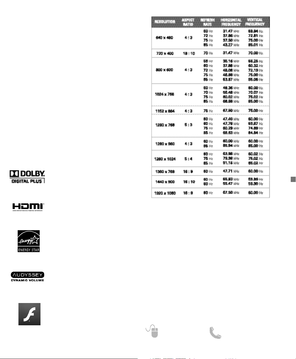
PC RESOLUTION CHART
FCC INFORMATION __________
This equipment has been tested and found to comply with the limits for a Class B digital device, pursuant to Part 15 of the FCC
Rules. These limits are designed to provide reasonable protection against harmful interference in a residential installation.
This equipment generates, uses and can radiate radio frequency
energy and, if not installed and used in accordance with the
instructions, may cause harmful interference to radio communications. However, there is no guarantee that interference will
not occur in a particular installation. If this equipment does
cause harmful interference to radio or television reception,
which can be determined by turning the equipment off and on, the
user is encouraged to try to correct the interference by one or
more of the following measures:
– Reorient or relocate the receiving antenna.
– Increase the separation between the equipment and receiver.
– Connect the equipment into an outlet on a circuit different from
that to which the receiver is connected.
– Consult the dealer or an experienced radio/TV technician for help.
CAUTION: FCC Regulations state that improper modifications or
unauthorized changes to this unit may void the user’s authority to
operate the unit.
As an Energy Star® Partner, Sanyo
Manufacturing Corporation has
determined that this product meets
the Energy Star® guidelines for energy
efficiency.
HDMI, the HDMI Logo and HighDefinition Multimedia Interface are
trademarks or registered trademarks of
HDMI Licensing LLC in the United
States and other countries.
This Class B digital apparatus complies with Canadian
ICES-003.
Manufactured under license from
Audyssey Laboratories. U.S. and
foreign patents pending. Audyssey
Dynamic Volume
®
is a registered
trademark of Audyssey Laboratories.
SPECIFICATIONS
Power Requirement: Source: AC 120V, 60Hz
AC Power Consumption: Weight:
DP42861 132 watts 33 lbs.
DP46861 150 watts 41 lbs.
Dimensions:
MODEL WIDTH HEIGHT DEPTH
DP42861 40.0 26.4 9.2
w/o stand 24.4 4.0
DP46861 43.9 29.4 10.6
w/o stand 26.6 4.6
NOTE: Dimensions are in inches
Adobe
®
, Adobe Flash®, and Flash
Lite®are either registered trademarks
or trademarks of Adobe Systems
Incorporated in the United States
and/or other countries.
TRADEMARKS
Manufactured under license from
Dolby Laboratories. Dolby and the
double-D symbol are trademarks of
Dolby Laboratories.
Page 4
4
Need help? www.sanyoctv.com 1-800-877-5032
CONTENTS
IMPORTANT SAFETY INSTRUCTIONS . . . . . . . . . . . . . . . 2
FCC INFORMATION . . . . . . . . . . . . . . . . . . . . . . . . . . . . . . . .3
TRADEMARKS . . . . . . . . . . . . . . . . . . . . . . . . . . . . . . . . . . . .3
PC RESOLUTIONS . . . . . . . . . . . . . . . . . . . . . . . . . . . . . . . . . .3
CONTENTS . . . . . . . . . . . . . . . . . . . . . . . . . . . . . . . . . . . . . . .3
SPECIFICATIONS . . . . . . . . . . . . . . . . . . . . . . . . . . . . . . . . . .4
PROTECTING THE LCD SCREEN . . . . . . . . . . . . . . . . . . . . .4
HANDLING PRECAUTIONS . . . . . . . . . . . . . . . . . . . . . . . . .4
POSITIONING THE LCD HDTV . . . . . . . . . . . . . . . . . . . . . . .4
STAND ASSEMBLY / WALL MOUNTING . . . . . . . . . . . . . 5
GETTING STARTED—
Remote Control Battery Installation . . . . . . . . . . . . . . . .5
Antenna Connections for off-air or cable . . . . . . . . . . .5
BACK PANEL JACKS . . . . . . . . . . . . . . . . . . . . . . . . . . . . . . .6
A/V CONNECTIONS . . . . . . . . . . . . . . . . . . . . . . . . . . . . . . . .7
REMOTE CONTROL OPERATION . . . . . . . . . . . . . . . . . . . . .8
POWER CONNECTION / INITIAL CHANNEL SEARCH . . .9
ON-SCREEN MENU OPERATION—
Inputs . . . . . . . . . . . . . . . . . . . . . . . . . . . . . . . . . . . . . . . . . .9
Setup . . . . . . . . . . . . . . . . . . . . . . . . . . . . . . . . . . . . . . . . . .9
Menu Language . . . . . . . . . . . . . . . . . . . . . . . . . . . . . .9
Digital Caption . . . . . . . . . . . . . . . . . . . . . . . . . . . . . . .9
Clock Timer . . . . . . . . . . . . . . . . . . . . . . . . . . . . . . . . .10
AV Connections . . . . . . . . . . . . . . . . . . . . . . . . . . . . .10
- Video 2 Setting . . . . . . . . . . . . . . . . . . . . . . . . . . . .10
- HDMI CEC . . . . . . . . . . . . . . . . . . . . . . . . . . . . . . . .10
No Signal Shut-off . . . . . . . . . . . . . . . . . . . . . . . . . . .10
Mode (Home/Store) . . . . . . . . . . . . . . . . . . . . . . . . . .10
Network . . . . . . . . . . . . . . . . . . . . . . . . . . . . . . . . . . . .10
V-Chip . . . . . . . . . . . . . . . . . . . . . . . . . . . . . . . . . . . . . .10
Channel . . . . . . . . . . . . . . . . . . . . . . . . . . . . . . . . . . . . . .11
Channel Search . . . . . . . . . . . . . . . . . . . . . . . . . . . . .11
Channel Scan Memory . . . . . . . . . . . . . . . . . . . . . . .11
Picture . . . . . . . . . . . . . . . . . . . . . . . . . . . . . . . . . . . . . . . .12
Manual Picture Settings . . . . . . . . . . . . . . . . . . . . . .12
Energy Saver . . . . . . . . . . . . . . . . . . . . . . . . . . . . . . . .12
Light Sensor . . . . . . . . . . . . . . . . . . . . . . . . . . . . . . . .12
H-Size and V-Size . . . . . . . . . . . . . . . . . . . . . . . . . . .12
Pix-Shape Settings . . . . . . . . . . . . . . . . . . . . . . . . . .13
Sound . . . . . . . . . . . . . . . . . . . . . . . . . . . . . . . . . . . . . . . . .13
aaManual Sound Settings . . . . . . . . . . . . . . . . . . . . . . .13
PHOTO/VIDEO VIEWER . . . . . . . . . . . . . . . . . . . . . . . . . . . .14
PC CONNECTIONS AND SETTINGS . . . . . . . . . . . . . . . . .15
WARRANTY . . . . . . . . . . . . . . . . . . . . . . . . . . . . . . . . . . . . . .16
GNU GENERAL PUBLIC LICENSE . . . . . . . . . . . . . . . . . . .17
POSITIONING THE HDTV
•
Always use a firm and flat surface when positioning
your HDTV.
•
Do not position the unit in a confined area.
•
Allow adequate space for proper ventilation.
•
Do not position the HDTV where it is easily reachable
by small children and may present risk of injury.
•
Once HDTV is positioned, remove the protective film
covering the front cabinet.
NOTE: Button area on bottom right hand corner will be
more accessible once film is removed.
“The American Academy of Pediatrics discourages
television viewing for children younger than two years
of age”
PROTECTING THE LCD SCREEN
CAUTION: The screen can be damaged if it is not
maintained properly.
•
Do not use hard objects such as hard cloth or paper to
clean the screen.
•
Do not use excessive pressure when cleaning the
screen; excessive pressure can cause permanent
discoloration or dark spots.
•
NEVER spray liquids on the screen.
•
The use of a damp microfiber cloth is recommended.
HANDLING PRECAUTIONS
•
Handle by the cabinet only.
•
Handling by two or more people is recommended.
•
Never touch the screen when handling.
•
Handling damage is not covered under warranty.
•
Do not remove the protective film covering the front
cabinet while handling the HDTV.
Please read before
operating your HDTV!
CONTAINS MERCURY LAMPS,
DISPOSE OF PROPERLY
RECYCLING OF SANYO TELEVISIONS:
SANYO television customers should contact
MRM Recycling at 888-769-0149 or visit their
website at www.mrmrecycling.com regarding
SANYO’s waste management plan.
Page 5
5
Need help? www.sanyoctv.com 1-800-877-5032
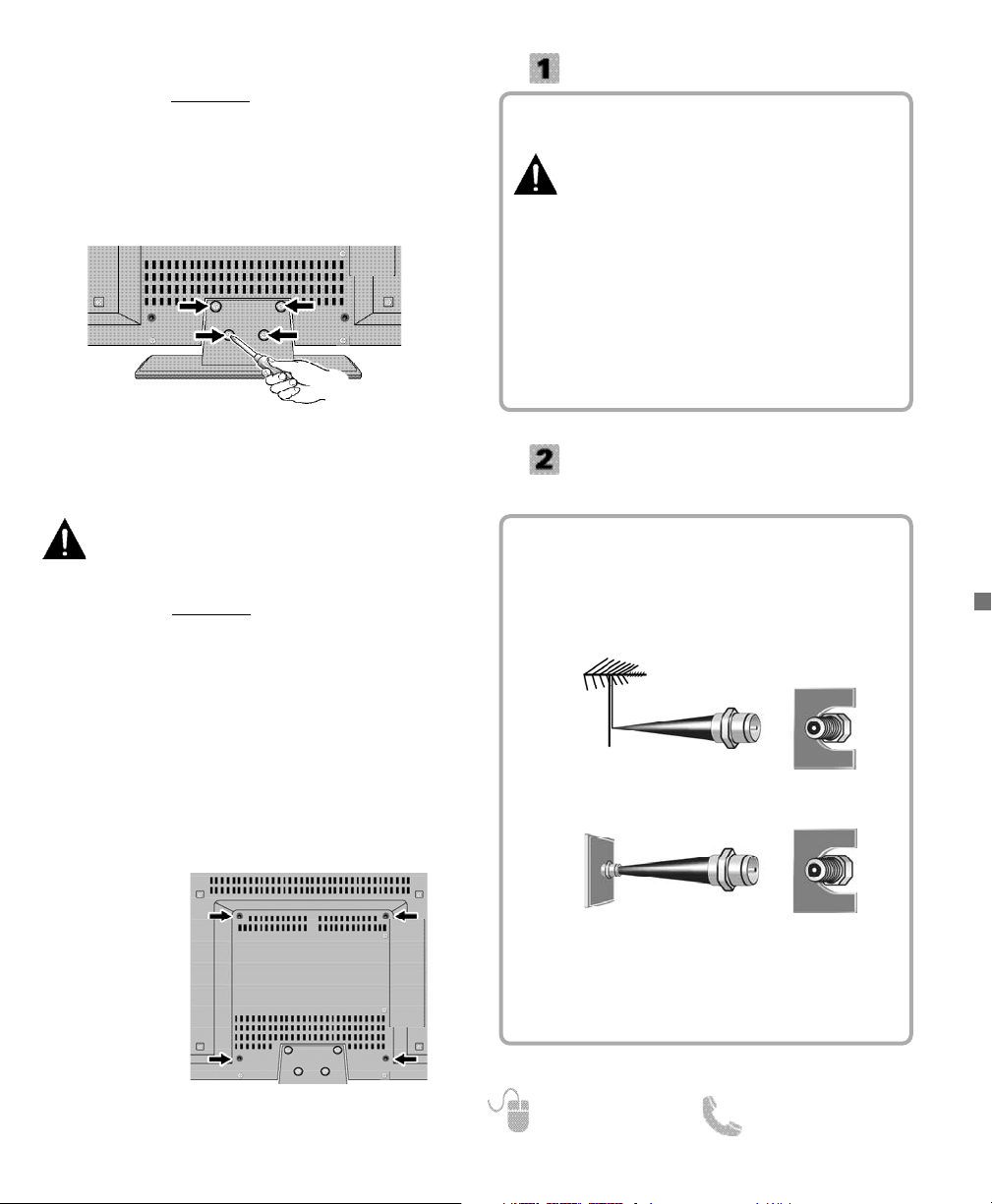
Hook up your antenna or your cable service to the
HDTV’s ANT terminal with the use of a 75 OHM
coaxial cable.
NOTE: Keep your indoor antenna at least 3 ft. away
from the television set and any other electronic
equipment.
The tuner in this HDTV can receive:
•
Digital and Analog off air signals from an antenna
• Analog or ClearQAM cable channels from a direct
Cable TV connection.
GETTING STARTED
Install two (2) “AAA” batteries in the remote control.
(Not included)
To ensure safe operation, please observe
the following precautions:
• Replace both batteries at the same time. Do not use
a new battery with a used battery.
• There’s a risk of explosion if a battery is replaced
by an incorrect type.
• Do not expose the Remote Control unit to moisture
or heat.
• Be sure to match the “+” and “–” signs on the
batteries with marks inside the remote control.
ANTENNA CONNECTION FOR
OFF-AIR SIGNALS OR CABLE
ANTENNA
CABLE
ANALOG / DIGITAL
ANTENNA IN
BATTERY INSTALLATION
Wall mounting of the HDTV must be performed
by a skilled person.
If stand base disassembly is required:
1
Place HDTV face down
on a padded or cushioned
flat surface to protect the screen and finish.
2
Remove the four (4) screws securing the foot stand.
CAUTION: Hold the stand firmly as you remove the
last screw.
Use the screws you would use to attach the stand base
to secure the HDTV to a wall mounting kit.
NOTE: Wall mounting kit is not included.
VESA standard interface: 400 x 400
Mounting screws measurements:
M6 (6mm) Diameter, Length—12mm (maximum)
WALL MOUNTING (OPTIONAL)
Wall Mounting
Inserts
NOTE: Skip these steps if you are wall mounting the TV.
1
Place HDTV face down on a padded or cushioned
flat surface to protect the screen and finish.
2
Carefully insert the stand base to the bottom of the
HDTV and secure the base by inserting 4 screws as
indicated in the diagram below.
NOTE: Stand base screws are located in the literature
package.
3
Position the HDTV on a firm and flat surface with
adequate space for proper ventilation.
STAND ASSEMBLY ___________
Page 6
6
Need help? www.sanyoctv.com 1-800-877-5032
GETTING STARTED
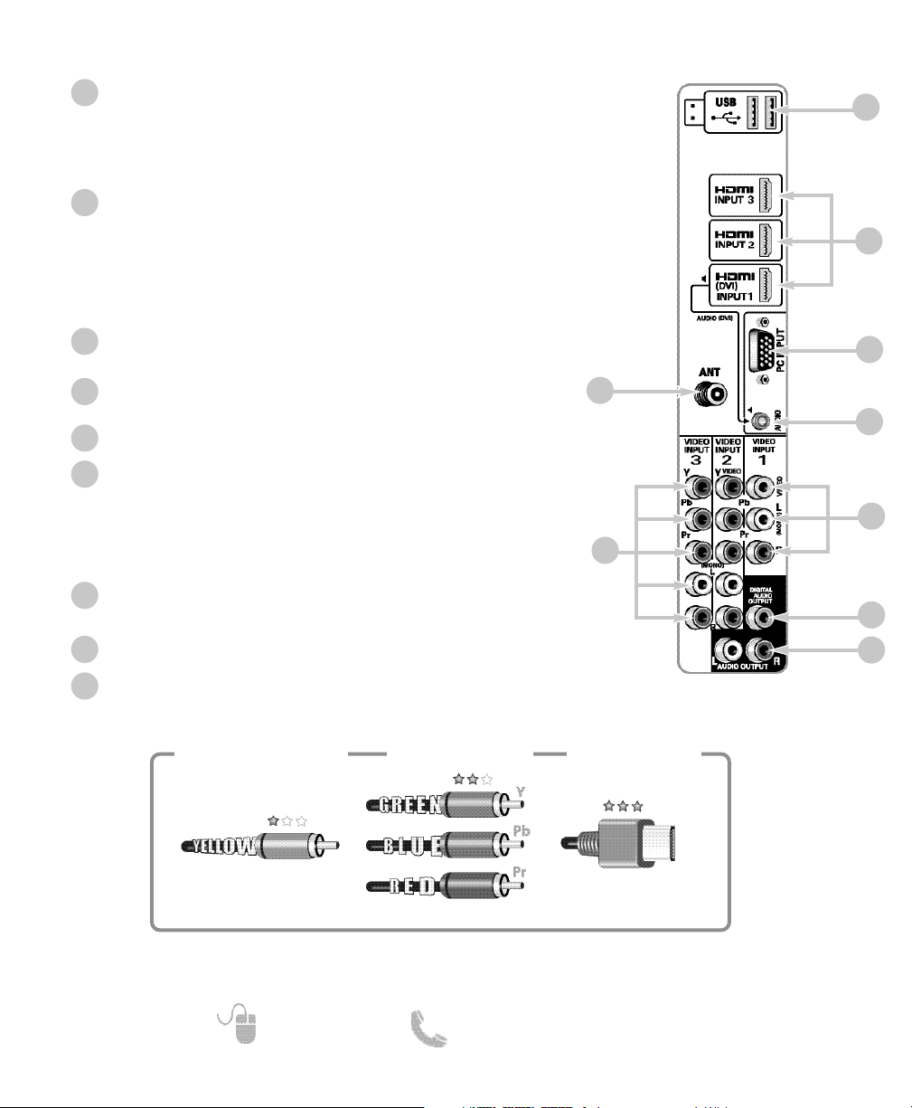
HDTV INPUT/OUTPUT REFERENCE
HDTV BACK PANEL
5
2
3
USB Input
View pictures stored in a USB flash drive or connect to the internet with the USB Wireless dongle.
NOTE: Please refer to the Internet Ready HDTV Guide for the
proper connection methods.
HDMI (INPUT1, INPUT2, & INPUT3)
An all digital Audio/Video interface that can accept uncompressed video signals up to 1080p for the very best picture
possible with the use of a single HDMI cable.
NOTE: A DVI connection is possible via the HDMI (DVI) INPUT1
using an appropriate adapter and connecting the audio to
the stereo mini AUDIO jack.
PC Input
Monitor RGB (D-SUB)
AUDIO mini stereo jack (3.5mm)
For AUDIO signal from PC or DVI device.
Analog / Digital Antenna Input
Component AV Input (VIDEO2 or VIDEO3)
Green (Y), blue (Pb), and red (Pr) Video inputs plus the white
and red Audio inputs.
NOTE: A composite connection is possible via VIDEO INPUT2
using the Y (VIDEO) jack and the L/R audio jacks. (See
Video2 Setting on page 10.)
Composite AV Input (VIDEO1)
Yellow (Video), plus white and red (Audio) input jacks.
Digital Audio Output (Coaxial)
Analog Stereo Audio Out (L/R) Jacks
1
2
3
4
5
6
7
8
Composite
Component
NOTE: Composite, Component, and DVI video connections need their appropriate audio connections.
High Definition image available from HD signals and HD equipment.
Standard Definition
High Definition
Optimum
High Definition
H D M I
(or DVI to HDMI
cable/adapter)
7
6
1
4
8
9
9
Page 7
7
Need help? www.sanyoctv.com 1-800-877-5032
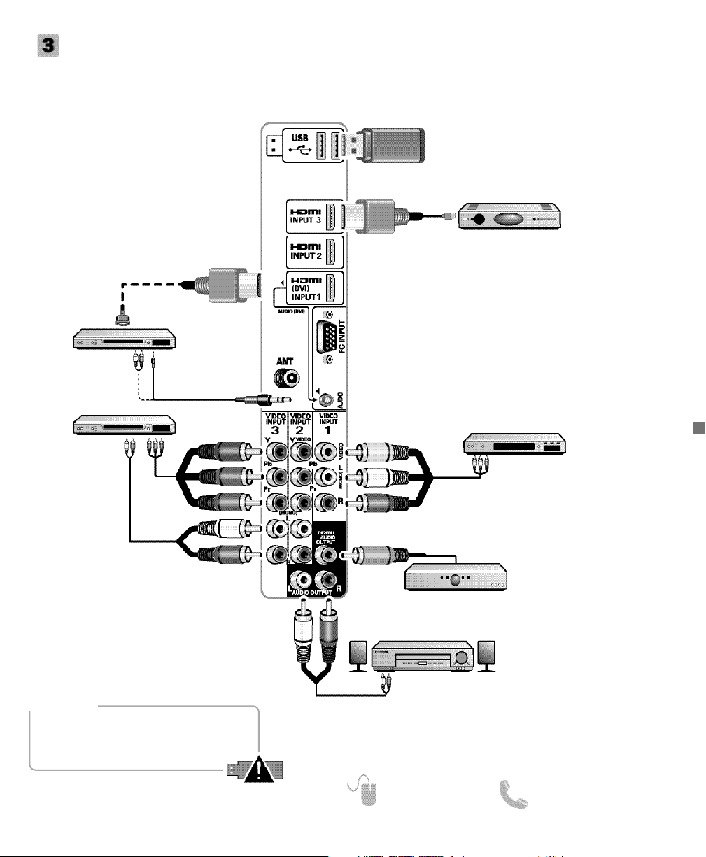
GETTING STARTED
AUDIO / VIDEO CONNECTIONS
DVD PLAYER
(or similar device)
VCR
(or analog device)
MULTICHANNEL
RECEIVER
NOTE: Audio/Video cables
are not supplied
Component connections will accept SDTV,
EDTV and HDTV video signals. Use them
for great image quality from digital
devices.
NOTE: Always match the color of your
device’s output jack, the connector
and the HDTV’s input jack.
SATELLITE RECEIVER
(or similar device)
USB FLASH
DRIVE OR
DONGLE
HDMI (DVI) INPUT1 can be used to
hookup a DVI device with the use of an
appropriate DVI to HDMI cable or adapter.
(AUDIO DVI jack needs to be hooked up to
the DVI device as well.)
NOTE: HDMI INPUT1 may also be used to
hookup any digital device with an
HDMI output, without the use of
the AUDIO (DVI) jack.
USB input jack is used to connect a USB mass
storage device (not included) to display digital images on
your HDTV, or hookup a USB Wireless dongle (included)
to connect your HDTV to your local area network (LAN).
DVI
HDMI INPUT1, 2 & 3 are used to hookup HD digital
devices such as a Blu-ray player, HD Cable Box, HD
Satellite Receiver or Video-game System.
Connect your digital device’s HDMI output to any of
the three (3) HDMI inputs on your HDTV with the use
of an HDMI cable.
Audio Output L/R jacks are used to
hookup an external stereo Amplifier.
(Do not connect external speakers
directly to the HDTV.)
STEREO
AMPLIFIER
Composite connections are used to hookup analog
equipment such as a VCR or an older DVD player.
NOTE: Always match the color of your device’s
output jack, the connector, and the HDTV’s
input jack.
Digital Audio Output is used to
hookup a multichannel receiver
with the use of a phono-type digital
audio cable.
DVD PLAYER
(or similar device)
NOTE: An active internet connection and wireless modem
is needed to connect your
HDTV using the USB dongle.
WARNING
Wireless USB adapter is not a toy. Do not
separate adapter from extension case.
Small parts can be a choking hazard to
children if swallowed.
Page 8

8
Need help? www.sanyoctv.com 1-800-877-5032
REMOTE CONTROL OPERATION
Selects the video source to view.
Turns your HDTV On or Off.
Displays on-screen Help menu.
Pressing it twice restores your HDTV to
its factory settings. All user customized
settings will be cleared.
Cycles through the available aspect
ratios. The different settings either
stretch, zoom, or fill the image on your
screen. Bars may appear on top and bottom of your screen (or on left and right
sides) depending on the broadcasted signal or program. (See page 13)
Cycles through the available Caption
modes (when available.)
Allows for the direct selection of digital
subchannels. For example: to select
channel 39.1 press the 3 and 9 keys,
followed by the dash ––, and 1 keys.
Increases or decreases the audio level.
Select channels directly.
For channels 100 and up, press and hold
the first number, then enter the remaining
two numbers.
Switch between current channel and last
selected channel or input.
Displays or hides the on-screen menu.
Scan through the channels in the memory
database.
Move the on-screen cursor in the
desired direction, press the ENTER key
to select highlighted options.
Operate playback functions when viewing
video files from a USB flash drive or from
an internet application.
Displays on-screen Help menu.
Access the VUDU app directly.
(Internet access requiered.)
Exits the on-screen menu.
Mute or restore the sound.
Use the on-screen QUIK menu to access
Video and Sound modes directly, or the
AUDIO (stereo, mono, SAP) and Sleep
Timer features.
Opens the Sanyo Net Apps menu screen.
Access the NETFLIX app directly.
(Internet access requirered.)
Page 9
9
Need help? www.sanyoctv.com 1-800-877-5032
1. PLUG IN AC POWER CORD
120V AC, 60Hz
2. TURN ON TV (PRESS POWER BUTTON)
Wait for on-screen instructions to set an Initial Energy
Saving Mode, and perform an Initial Channel/Signal
Search.
3. TV SET LOCATION SELECTION:
Select “Home Mode” to set the HDTV’s backlight to
an Energy Star qualified level, or select “Store
Mode”to set the backlight to a retail display level.
Press ENTER on the desired option to continue.
4. CHANNEL AND AV SIGNAL SEARCH:
Select the Signal Search option and press ENTER to
perform a channel search from an Antenna or a direct
Cable connection, and a signal search from devices
hooked up to the HDTV’s AV input jacks.
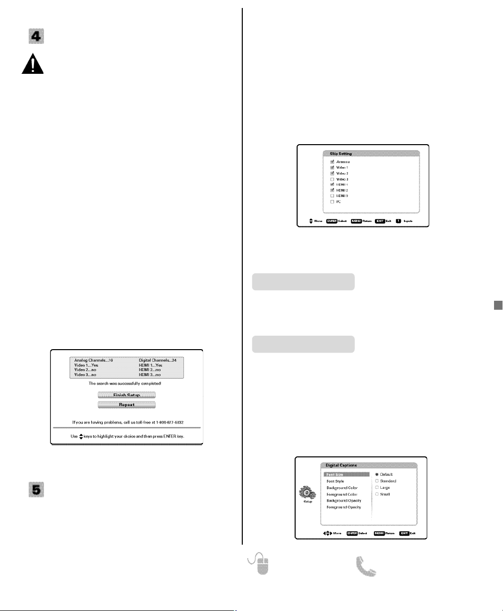
5. CHANNEL AND SIGNAL SETUP SCREEN
The final setup screen displays analog and digital
channels found as well as AV inputs detected.
Select Finish Setup and press ENTER to go to one of
your HDTV’s inputs.
NOTE: If you wish to repeat the Signal Search
process select Repeat.
GETTING STARTED
INITIAL CHANNEL SEARCH
Before proceeding, please make sure to hook up
your antenna or cable connection and all AV
equipment correctly to your HDTV.
AV INPUT SELECTION
Press the INPUT key to select the correct AV input for the
video source you wish to watch.
NOTE: Unused AV inputs may be disabled with the Input
Skip Setting feature (see page 10).
INPUTS ___________________________
ON-SCREEN MENU OPERATION
Choose between English, Spanish and French for your
On Screen menu’s display language.
Press ENTER on the desired language.
Menu Language
SETUP
_______________________
Captioning is textual information transmitted along with
the picture and sound. Turning Captioning ON (by
pressing the CAPTION key during normal TV viewing)
causes the HDTV to open these captions (digital or analog) and superimpose them on the screen.
NOTE: Local broadcasters decide which caption signals
to transmit.
Use the CURSOR and keys to modify Font,
Background, and Foreground of digital caption text.
Display the On Screen menu and use the CURSOR
keys to select Setup. Press ENTER.
Digital Caption
Display the On Screen menu and use the CURSOR
keys to select Inputs. Press ENTER.
Inputs allows the direct selection of any AV input and
the removal of unused inputs from the AV input loop.
Use the CURSOR keys to select the desired AV input
and press ENTER.
To manage the available inputs press the 1 key to enter
the Skip Setting screen. Use the CURSOR keys to
select an AV input and press ENTER to disable
(uncheck) or enable (check) the highlighted input.
Page 10
10
Need help? www.sanyoctv.com 1-800-877-5032
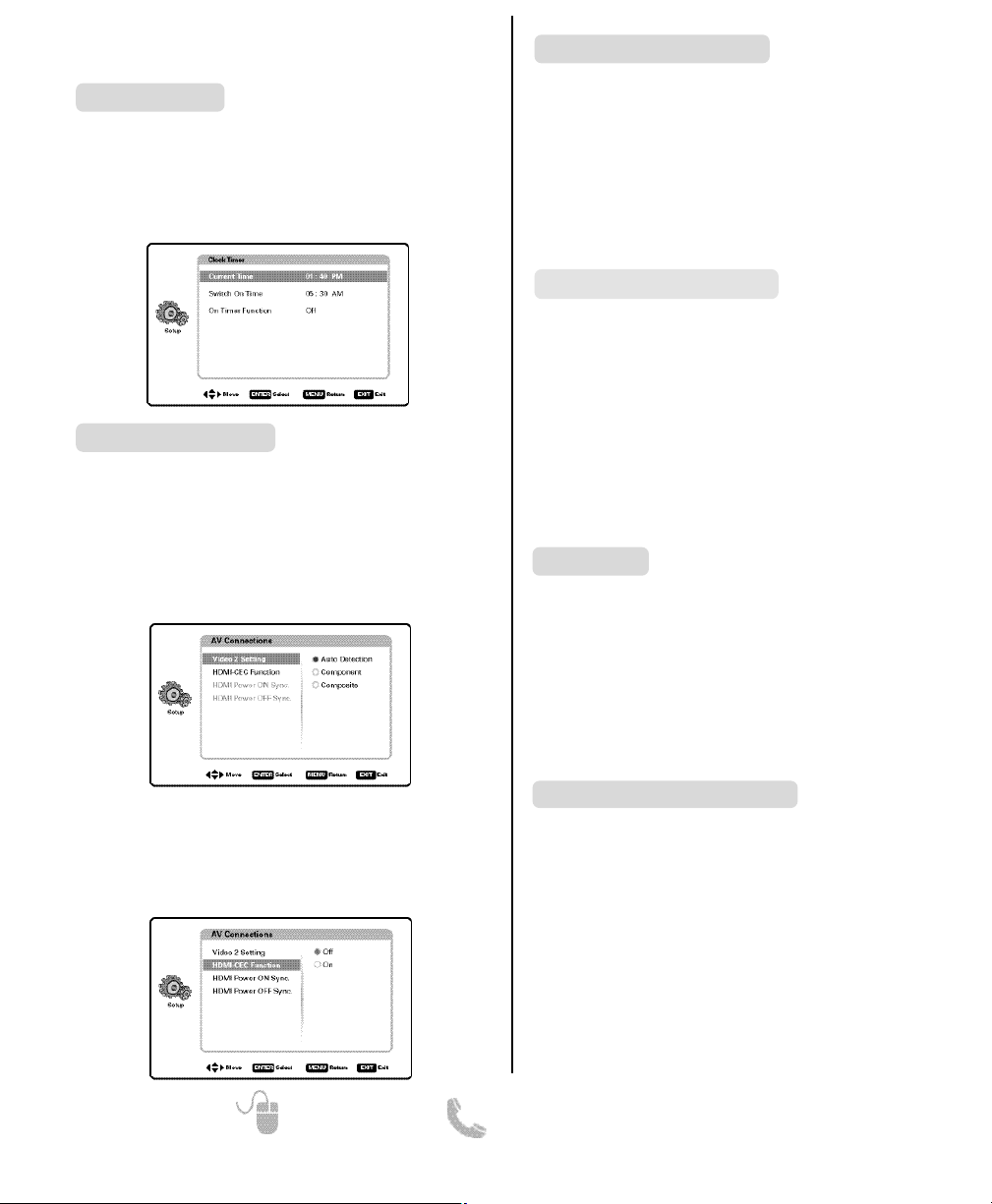
Video 2 Setting - Use this feature to establish either
a Component or Composite connection to the VIDEO
INPUT 2 jacks on your HDTV.
Use the CURSOR keys to select the type of connection you’ll use in VIDEO INPUT 2.
Press ENTER, a blue mark will appear next to the selected option indicating it is the active option.
HDMI CEC - Use the HDMI-CEC Function to enable or
disable all available CEC functions.
HDMI Power ON Sync and Power OFF Sync enable
specific features including the automatic power ON
process and power OFF process.
Use the Network option to configure your HDTV’s setup
to your Local Area Network (LAN) and enjoy internet
based content directly on your TV.
A subscription to an Internet Service Provider and a
Sanyo USB Wireless Dongle is needed.
Please refer to the Internet Ready HDTV Guide for more
information.
This feature allows you to set a Current Time for your
HDTV and enable a Switch On Time for the HDTV to
turn on at a specific time of day.
When On Timer Function is set to ON, the TV will
automatically turn on at the previously set Switch on
Time.
Clock timer
SETUP
(CONTINUED) __________________
ON-SCREEN MENU OPERATION
AV Connections
Network
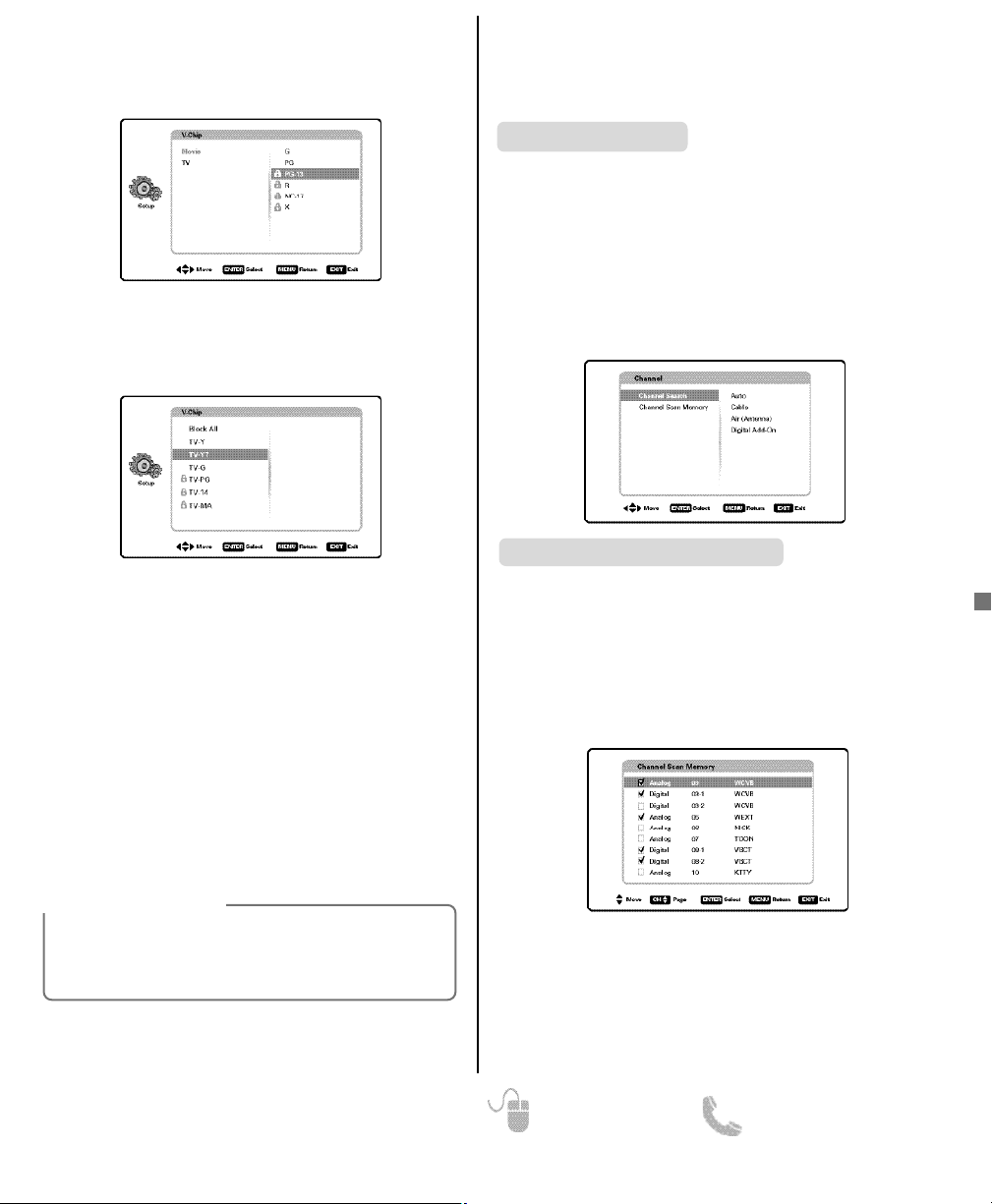
Use this feature to automatically block programs with
content you deem inappropriate for viewing by children.
NOTE: This feature is designed to comply with the
United States of America’s FCC V-Chip regulations. Therefore, it may not function with broadcasts that originate in other countries.
ADJUSTING THE V-CHIP RATINGS
Select ON and press ENTER. Select Adjust (Standard)
and press ENTER.
NOTE: Blocking a rating will automatically block all
higher ratings. Unblocking a rating will automatically unblock all lower ratings.
V-Chip (parental control)
When No Signal Shut-off feature is set to ON, it will
allow the HDTV to automatically turn off when no
video and/or audio signals are being received.
NOTES: By factory default, this feature is set to ON.
TV will automatically turn off if no AV signals
are received in a time span of 15 minutes.
Use the CURSOR keys to select On or OFF and
press ENTER.
No Signal Shut-Off
Use the Mode (Home/Store) option if you would like to
change the initial Energy Saving Mode chosen at
HDTV’s first power on.
Home Mode - Configured for saving energy and power
consumption reduction.
Store Mode - Configured for high brightness and
contrast for display at retailer store.
NOTE: Only Home Mode qualifies for Energy Star.
Press ENTER on the desired mode.
Mode (Home/Store)
Page 11
11
Need help? www.sanyoctv.com 1-800-877-5032
CHANNEL _________________________
Auto – Search the detected mode, Cable or Air.
Cable – Search for analog and unscrambled (ClearQAM)
digital cable channels.
Air (Antenna) – Search for analog and digital off-air
channels.
Digital Add-On – Search for digital channels adding newly
found digital channels to the channel map database.
NOTE: Digital Add-On option is not available when the
current mode is Cable.
Channel Search
Display the On Screen menu and use the CURSOR
keys to select Channel. Press ENTER.
ON-SCREEN MENU OPERATION
Channel Scan Memory lists all Analog and Digital channels found. It also lists Analog channels that were not
found, which can be added.
Use the CURSOR keys to move the channel select
bar through all enabled and disabled channels.
NOTE: You may use the
CH
keys to change page.
Press ENTER to enable or disable the selected channel.
Channel Scan Memory
For V-Chip (Movie) ratings select Movie and press
ENTER, and then select the desired MPAA rating limit.
Press the EXIT key to close the V-Chip menu.
For V-Chip (TV) ratings select TV and press ENTER. Use
the CURSOR keys to select a rating and press
ENTER. Use the CURSOR keys to set the rating’s
status as Blocked or Viewable. Once ratings are set,
press the EXIT key to close the V-Chip menu.
NOTE: Some TV ratings offer more detailed settings
such as Dialogue, Language, Sexual, and
Violence.
ADVANCED V-CHIP SYSTEM (RRT5)
RRT5 (V-Chip Regional Ratings 5) is an advanced V-Chip
ratings system for over the air digital channels. When the
HDTV detects compatible RRT5 data, it’s downloaded &
stored in memory, and the Setup V-Chip screen is then
modified to show the Adjust (Advanced) option.
Use the CURSOR and keys to highlight the
different options, and use the ENTER key to block or
unblock the selected rating.
NOTE: When vertical scroll bars appear, press
CURSOR
to gain access to the additional ratings.
MORE INFORMATION
Additional information about MPAA (Motion
Picture Association of America) and V-Chip rating
can be found at: www.mpaa.org and www.vchip.org, respectively.
NOTE: For information on local digital channels, visit
www.antennaweb.org
Page 12

12
Need help? www.sanyoctv.com 1-800-877-5032
PICTURE _________________________
ON-SCREEN MENU OPERATION
Display the On Screen menu and use the CURSOR
keys to select Picture. Press ENTER.
You may choose a Picture Mode between Standard,
Vivid, Theater, and Stadium which have predetermined
picture parameter values, or choose the Custom option
for personalized picture settings.
NOTE: Each AV input can have its own picture mode
(predetermined or custom.)
MANUAL (CUSTOM) PICTURE SETTINGS
Custom parameters to adjust include:
•
Color
•
Tint
•
Contrast
•
Brightness • Sharpness• Color Temperature
The Advanced Control option allows for the adjustment
of additional parameters such as:
•
Signal Balancer• Noise Reduction
•
White Balance• Dynamic Contrast
CUSTOMIZING PICTURE SETTINGS
Use the CURSOR keys to highlight the picture parameter you wish to adjust. Press the ENTER key to enter the
value adjustment screen. Modify the selected parameter’s
value by pressing the CURSOR keys.
NOTE: CURSOR keys select the next/previous
parameter without returning to the previous
menu screen.
Once adjustments are complete, press the EXIT key to
return to normal TV viewing.
ADDITIONAL PICTURE OPTIONS:
Select Picture Options to access power consumption
reduction features such as ECO and Light Sensor, as
well as horizontal and vertical stretch parameters.
ECO (ENERGY SAVER)
ECO settings control the LCD backlight brightness to
reduce power consumption.
• Level 1: Energy Saver feature is off.
• Level 2: Lower power consumption.
• Level 3: Lowest power consumption.
Press ENTER on the desired level.
NOTE: ECO key on remote may also be used as a short-
cut to modify the Energy Saver settings.
LIGHT SENSOR
This feature detects ambient room light brightness and
uses that reading to control the panel brightness level
and picture parameters to reduce the HDTV’s power
consumption.
NOTE: When room lighting is dark, the panel bright-
ness and/or the picture setting parameters such
as brightness and contrast are lowered. When
room lighting is bright, parameters are affected
opposite.
H-SIZE & V-SIZE
H-Size function adjusts the screen’s horizontal dimensions, while the V-Size function adjust’s the screen’s
vertical dimensions.
Once adjustments are complete, press the EXIT key to
return to normal TV viewing.
Page 13

13
Need help? www.sanyoctv.com 1-800-877-5032
Pix1 Shows a standard definition 4:3 image in its
original format, a 16:9 wide image is slightly
compressed horizontally.
Pix2 Fills the entire image on the screen. A 4:3 image
is slightly stretched horizontally.
Pix3 Image is stretched vertically in comparison with
Pix2.
Pix4 Image is stretched horizontally in comparison
with Pix3.
Pix5 Similar to Pix2, image is enlarged horizontally
but in a linear proportion in which center portion
of screen is stretched less than the sides.
Pix6 Similar to Pix1 with no Overscan*.
Pix7 Similar to Pix2 with no Overscan*.
* Overscan permits the image to slightly exceed bot-
tom and top edge limitations.
NOTE: Pix6 and Pix7 are not optimal for Standard
Definition content (a thin white line may appear
near edge of screen). Pix6 and Pix7 use is recommended only for PC signal through HDMI.
Pix-Auto (AFD) Active Format Description.
Datacarried in the video stream includes coded picture
frame information of the actual image, allowing the TV
to adjust the Pix-Shape automatically.
NOTE: AFD Pix-Shape mode is available only for Digital-
RF input.
UNDERSTANDING PIX-SHAPE
NOTE: Images on left are for a 4:3 transmission while
images on right are for a 16:9 transmission.
SOUND __________________________
ON-SCREEN MENU OPERATION
Display the On Screen menu and use the CURSOR
keys to select Sound. Press ENTER.
You may choose a Sound Mode between Standard, Vivid,
Theater, and Clear Voice which have predetermined
audio parameter values, or choose the Custom option for
personalized picture settings.
MANUAL (CUSTOM) SOUND SETTINGS
The Custom option provides different parameters that
can be personally adjusted:
•
Bass & Treble • Bass Extension
•
Audyssey Dynamic Volume
1
•
Equalizer
•
Lyp-Sync (Adjust the audio delay.)
1
Audyssey Dynamic Volume solves the problem of large variations in volume level between television programs, commercials,
and between the soft and loud passages of movies. Audyssey
Dynamic EQ is integrated into Dynamic Volume so that as the playback volume is adjusted automatically, the perceived bass
response, tonal balance, surround impression and dialog clarity
remain the same.
CUSTOMIZING SOUND SETTINGS
Use the CURSOR keys to highlight the sound parameter you wish to adjust. Press the ENTER key to enter the
value adjustment screen. Modify the selected parameter’s
value by pressing the CURSOR keys.
NOTE: CURSOR keys select the next/previous
parameter without returning to the previous
menu screen.
Once adjustments are complete, press the EXIT key to
return to normal TV viewing.
Page 14

14
Need help? www.sanyoctv.com 1-800-877-5032
MEDIA APPS_______________________
ACCESSING THE MEDIA APPS
Display the On Screen menu and use the CURSOR
keys to select Media Apps. Press ENTER.
NOTE: When a USB flash drive is connected to the
HDTV, the Photo option is automatically selected.
USING THE PHOTO VIEWER FEATURE
Select the Photo option and press ENTER.
Use the CURSOR keys to select an available
picture on the thumbnail screen.
NOTE: If pictures are in a specific folder, select folder and
press
ENTER
to view thumbnail previews.
Press ENTER on a thumbnail photo to show the image on
the entire screen (Full view mode).
Once in Full View mode:
Use the CURSOR keys to change picture.
Press ENTER to show the full view options menu.
•
Rotate
•
Zoom In
•
Zoom Out
•
Pan
•
Start Slideshow
•
Browse Photo
STARTING A SLIDE SHOW
The slideshow displays one picture after another automatically in a timed and sequential manner.
Pressing the 1 key will trigger the slideshow starting
from the highlighted thumbnail picture.
NOTE: You can use the Slideshow Setup option (by
pressing the
3
key) to enable or disable the
Shuffle and Quick Change features.
USB JPEG VIEWER MENU
Press MENU when in Full View or Slideshow mode to
display the USB On screen menu.
Select a Picture Mode or configure Picture Adjustments
such as Color, Tint, Contrast, Brightness, Sharpness,
Dynamic Contrast, and Color Temperature.
NOTE: Picture Settings are separate configurations from
the settings in TV and AV inputs.
Enjoy viewing pictures and video files on your HDTV
with the use of a USB mass storage device hooked up to
the HDTV’s USB input.
USING THE MOVIE VIEWER FEATURE
Select the Movie option and press ENTER.
Use the CURSOR keys to select an available
movie file from the thumbnail screen.
NOTE: If videos are in a specific folder, select folder and
press
ENTER
to view thumbnail previews.
Press ENTER on a thumbnail file to start video playback.
MOVIE PLAYBACK CONTROLS
Once movie file has been selected and playback started,
use the ENTER key to pause playback at any time,
pressing ENTER again will resume playback.
To fast-forward movie playback press the CURSOR
key, to fast-rewind press the CURSOR key.
Use the RECALL key to stop playback and return to the
thumbnail screen.
NOTE: Finishing playback of a video file will also return
you to the thumbnail screen.
Enjoy Internet based content directly on your HDTV
through the use of an internet connection.
Access on-screen links to get the latest weather, news,
information, sports, stock updates, and content services
apps like VUDU movies and NETFLIX.
Please refer to the Internet Ready HDTV Guide for more
information.
NET APPS_________________________
Page 15

15
Need help? www.sanyoctv.com 1-800-877-5032
PC Setting
Auto Adjustment – Automatically adjusts display posi-
tion, dot clock and phase.
Dot Clock – Adjust the Dot frequency to match your
computer’s Dot frequency.
Phase – Adjust this parameter when the picture appears
to flicker or is blurred.
H-Position – Move the image horizontally.
V-Position – Move the image vertically.
Power Saving – Enable the HDTV to turn to Standby
Mode when computer is not in use.
PC Picture and Sound
Standard – Sets predetermined values to the Picture or
Sound parameters.
Custom – Adjust Contrast, Brightness, and Color
Temperature screen settings, and the Bass
and Treble audio settings.
NOTE: These settings do not affect normal TV viewing.
Laptop Display
When using your Sanyo HDTV to display a Laptop’s
screen display, holding down the Fn (or FN) key while
pressing the appropriate function key (F5, F7, F8, etc)
should cycle through different display modes between
the laptop and the HDTV.
Modes may include displaying only on the laptop
screen, on both the laptop and the HDTV, or displaying
only on the HDTV.
NOTE: Fn key and function key symbols on the laptop’s
keyboard may vary from one brand to another.
Hold down and press
PC OR LAPTOP
HDTV BACK
RGB Monitor
cable
Stereo mini
audio cable
NOTE: Sanyo recommends using a monitor cable that
includes a Ferrite Core.
DVI OUTPUT
JACK
RGB OUTPUT
JACK
Use your HDTV as a computer monitor by hooking up
your PC or Laptop to the TV with the use of an appropriate monitor cable (not included.)
Before connecting any cables, disconnect the AC
power cords of both the HDTV and PC from the
AC outlets.
Power on the HDTV and any other peripheral
equipment before powering on the computer.
To avoid an “Out of Range” condition please set your
PC’s output resolution to one compatible with your
HDTV. See PC Resolution chart on page 3.
NOTE: If computer has only DVI Output, a DVI to RGB
adapter will be required, or, a DVI to HDMI cable and
RCA audio cables (see HDMI (DVI) INPUT1 on page 7.)
PC INPUT
Page 16

16
Need help? www.sanyoctv.com 1-800-877-5032
Your Sanyo HDTV is registered at the time of purchase, please keep sales receipt for future reference.
For your protection in the event of theft or loss of this product, please fill in the information requested
below and KEEP IN A SAFE PLACE FOR YOUR OWN PERSONAL RECORDS.
Model No.______________________________ Date of Purchase _________________________
Serial No.______________________________ Purchase Price ___________________________
Where Purchased_________________________
(Located on back of unit)
Sanyo Manufacturing Corp.
3333 Sanyo Road, Forrest City, AR 72335
ONE-YEAR LIMITED PARTS AND LABOR WARRANTY
THIS LIMITED PARTS AND LABOR WARRANTY IS VALID ONLY ON SANYO TELEVISIONS PURCHASED AND USED IN
THE UNITED STATES OF AMERICA, CANADA, AND PUERTO RICO, EXCLUDING ALL OTHER U.S. TERRITORIES AND
PROTECTORATES. THIS LIMITED WARRANTY APPLIES ONLY TO THE ORIGINAL RETAIL PURCHASER, AND DOES NOT
APPLY TO PRODUCTS USED FOR INDUSTRIAL OR COMMERCIAL PURPOSES.
WARRANTY APPLICATION
FOR ONE YEAR from the date of original retail purchase Sanyo Manufacturing Corporation (SMC) warrants this TV to
be free from manufacturing defects in materials and workmanship under normal use and conditions for parts and labor.
For the FIRST 90 DAYS from the date of original retail purchase, Sanyo Manufacturing Corporation will replace any
defective TV via exchange at the retailer. To ensure proper warranty application, keep the original-dated-sales receipt
for evidence of purchase. Return the defective TV to the retailer along with the receipt and the included accessories,
such as the remote control. The defective TV will be exchanged for the same model, or a replacement model of equal
value, if necessary. Replacement model will be contingent on availability and at the sole discretion of Sanyo
Manufacturing Corporation.
THE FOREGOING WARRANTY IS EXCLUSIVE AND IN LIEU OF ALL OTHER WARRANTIES OF MERCHANTABILITY OR
FITNESS FOR A PARTICULAR PURPOSE.
OBLIGATIONS
For one year
from the date of purchase, Sanyo Manufacturing Corporation warrants this product to be free from
defects in material and workmanship under normal use and conditions. During the first 90 days
under this warranty
for any manufacturing defect or malfunction Sanyo Manufacturing Corporation will provide a new TV via exchange at
the retailer.
HOW TO MAKE A CLAIM UNDER THIS WARRANTY
Please call 1-800-877-5032. Please be prepared to give us the television’s model number and serial number when you
call. The model number and serial number are printed on a label attached to the back of the unit.
For customer assistance, call toll free 1-800-877-5032.
This warranty expresses specific contractual rights; retail purchasers may have additional statutory rights which vary
from state to state.
(EFFECTIVE: March 1, 2007)
Page 17

17
Need help? www.sanyoctv.com 1-800-877-5032
This product incorporates the following software:
1. the software developed independently by or for
Sanyo Electric Co.,Ltd.,
2. the software owned by third party and licensed to
Sanyo Electric Co.,Ltd.,
3. the software licensed under the GNU General Public
License, Version 2 (GPL v2),
4. the software licensed under the GNU LESSER General
Public License (LGPL) and/or,
5. sourced software other than the software licensed
under the GPL and/or LGPL
For the software categorized as (3) and (4), please refer
to the terms and conditions of GPL v2 and LGPL, as the
case may be at:
http://www.gnu.org/licenses/old-licenses/gpl-2.0.html
http://www.gnu.org/licenses/old-licenses/lgpl-2.1.html
In addition, the software categorized as (3) and (4) are
copyrighted by several individuals. The copyright notice
of those individuals is written in the media to be provided upon request.
The GPL/LGPL software is distributed in the hope that it
will be useful, but WITHOUT ANY WARRANTY, without
even the implied warranty of MERCHANTABILITY or
FITNESS FOR A PARTICULAR PURPOSE.
At least three (3) years from delivery of products, Sanyo
Electric Co.,Ltd. will give to any third party who contact
us at the contact information provided below, for a
charge no more than our cost of physically performing
source code distribution, a complete machine-readable
copy of the corresponding source code covered under
GPL v2/LGPL.
Contact Information: GPL_Inquiries@SanyoTV.com
GNU GENERAL PUBLIC LICENSE
Version 2, June 1991
Copyright (C) 1989, 1991 Free Software Foundation, Inc., 51
Franklin Street, Fifth Floor, Boston, MA 02110-1301 USA
Everyone is permitted to copy and distribute verbatim
copies of this license document, but changing it is not
allowed.
Preamble
The licenses for most software are designed to takeway
your freedom to share and change it. By contrast, the
GNU General Public License is intended to guarantee
your freedom to share and change free software to make
sure the software is free for all its users. This General
Public License applies to most of the Free Software
Foundation's software and to any other program whose
authors commit to using it. (Some other Free Software
Foundation software is covered by the GNU Lesser
General Public License instead.) You can apply it to your
programs, too.
When we speak of free software, we are referring to
freedom, not price. Our General Public Licenses are
designed to make sure that you have the freedom to distribute copies of free software (and charge for this service if you wish), that you receive source code or can get
it if you want it, that you can change the software or use
pieces of it in new free programs; and that you know you
can do these things.
To protect your rights, we need to make restrictions
that forbid anyone to deny you these rights or to ask you
to surrender the rights. These restrictions translate to
certain responsibilities for you if you distribute copies of
the software, or if you modify it.
For example, if you distribute copies of such a program,
whether free or for a fee, you must give the recipients all
the rights that you have. You must make sure that they,
too, receive or can get the source code. And you must
show them these terms so they know their rights.
We protect your rights with two steps: (1) copyright the
software, and (2) offer you this license which gives you
legal permission to copy, distribute and/or modify the
software.
Also, for each author's protection and ours, we want to
make certain that everyone understands that there is no
warranty for this free software. If the software is modified by someone else and passed on, we want its recipients to know that what they have is not the original, so
that any problems introduced by others will not reflect
on the original authors' reputations.
Finally, any free program is threatened constantly by
software patents. We wish to avoid the danger that
redistributors of a free program will individually obtain
patent licenses, in effect making the program proprietary. To prevent this, we have made it clear that any
patent must be licensed for everyone's free use or not
licensed at all.
The precise terms and conditions for copying, distribu-
tion and modification follow.
Page 18

18
Need help? www.sanyoctv.com 1-800-877-5032
GNU GENERAL PUBLIC LICENSE
TERMS AND CONDITIONS FOR COPYING,
DISTRIBUTION AND MODIFICATION
0. This License applies to any program or other work
which contains a notice placed by the copyright holder
saying it may be distributed under the terms of this
General Public License. The "Program", below, refers to
any such program or work, and a "work based on the
Program" means either the Program or any derivative
work under copyright law: that is to say, a work containing
the Program or a portion of it, either verbatim or with
modifications and/or translated into another language.
(Hereinafter, translation is included without limitation in
the term "modification".) Each licensee is addressed as "you".
Activities other than copying, distribution and modification are not covered by this License; they are outside its
scope. The act of running the Program is not restricted,
and the output from the Program is covered only if its
contents constitute a work based on the Program (independent of having been made by running the Program).
Whether that is true depends on what the Program does.
1. You may copy and distribute verbatim copies of the
Program's source code as you receive it, in any medium,
provided that you conspicuously and appropriately publish on each copy an appropriate copyright notice and
disclaimer of warranty; keep intact all the notices that
refer to this License and to the absence of any warranty;
and give any other recipients of the Program a copy of
this License along with the Program.
You may charge a fee for the physical act of transferring
a copy, and you may at your option offer warranty protection in exchange for a fee.
2. You may modify your copy or copies of the Program
or any portion of it, thus forming a work based on the
Program, and copy and distribute such modifications or
work under the terms of Section 1 above, provided that
you also meet all of these conditions:
a) You must cause the modified files to carry promi-
nent notices stating that you changed the files and
the date of any change.
b) You must cause any work that you distribute or
publish, that in whole or in part contains or is
derived from the Program or any part thereof, to be
licensed as a whole at no charge to all third parties
under the terms of this License.
c) If the modified program normally reads com-
mands interactively when run, you must cause it,
when started running for such interactive use in
the most ordinary way, to print or display an
announcement including an appropriate copyright
notice and a notice that there is no warranty (or
else, saying that you provide a warranty) and that
users may redistribute the program under these
conditions, and telling the user how to view a copy
of this License. (Exception: if the Program itself is
interactive but does not normally print such an
announcement, your work based on the Program
is not required to print an announcement.)
These requirements apply to the modified work as a
whole. If identifiable sections of that work are not
derived from the Program, and can be reasonably considered independent and separate works in themselves,
then this License, and its terms, do not apply to those
sections when you distribute them as separate works.
But when you distribute the same sections as part of a
whole which is a work based on the Program, the distribution of the whole must be on the terms of this License,
whose permissions for other licensees extend to the
entire whole, and thus to each and every part regardless
of who wrote it.
Thus, it is not the intent of this section to claim rights or
contest your rights to work written entirely by you;
rather, the intent is to exercise the right to control the
distribution of derivative or collective works based on
the Program.
In addition, mere aggregation of another work not based
on the Program with the Program (or with a work based
on the Program) on a volume of a storage or distribution
medium does not bring the other work under the scope
of this License.
3. You may copy and distribute the Program (or a work
based on it, under Section 2) in object code or executable form under the terms of Sections 1 and 2 above
provided that you also do one of the following:
a) Accompany it with the complete corresponding
machine-readable source code, which must be distributed under the terms of Sections 1 and 2 above
on a medium customarily used for software interchange; or,
b) Accompany it with a written offer, valid for at least
three years, to give any third party, for a charge no
more than your cost of physically performing
source distribution, a complete machine-readable
copy of the corresponding source code, to be distributed under the terms of Sections 1 and 2 above
on a medium customarily used for software interchange; or,
c) Accompany it with the information you received as
to the offer to distribute corresponding source
code. (This alternative is allowed only for noncommercial distribution and only if you received the
program in object code or executable form with
such an offer, in accord with Subsection b above.)
Page 19

19
Need help? www.sanyoctv.com 1-800-877-5032
The source code for a work means the preferred form of
the work for making modifications to it. For an executable work, complete source code means all the
source code for all modules it contains, plus any associated interface definition files, plus the scripts used to
control compilation and installation of the executable.
However, as a special exception, the source code distributed need not include anything that is normally distributed (in either source or binary form) with the major
components (compiler, kernel, and so on) of the operating system on which the executable runs, unless that
component itself accompanies the executable.
If distribution of executable or object code is made by
offering access to copy from a designated place, then
offering equivalent access to copy the source code from
the same place counts as distribution of the source code,
even though third parties are not compelled to copy the
source along with the object code.
4. You may not copy, modify, sublicense, or distribute
the Program except as expressly provided under this
License. Any attempt otherwise to copy, modify, sublicense or distribute the Program is void, and will automatically terminate your rights under this License. However,
parties who have received copies, or rights, from you
under this License will not have their licenses terminated
so long as such parties remain in full compliance.
5. You are not required to accept this License, since you
have not signed it. However, nothing else grants you
permission to modify or distribute the Program or its
derivative works. These actions are prohibited by law if
you do not accept this License. Therefore, by modifying
or distributing the Program (or any work based on the
Program), you indicate your acceptance of this License to
do so, and all its terms and conditions for copying, distributing or modifying the Program or works based on it.
6. Each time you redistribute the Program (or any work
based on the Program), the recipient automatically
receives a license from the original licensor to copy, distribute or modify the Program subject to these terms and
conditions. You may not impose any further restrictions
on the recipients' exercise of the rights granted herein.
You are not responsible for enforcing compliance by
third parties to this License.
7. If, as a consequence of a court judgment or allegation of patent infringement or for any other reason (not
limited to patent issues), conditions are imposed on you
(whether by court order, agreement or otherwise) that
contradict the conditions of this License, they do not
excuse you from the conditions of this License. If you
cannot distribute so as to satisfy simultaneously your
obligations under this License and any other pertinent
obligations, then as a consequence you may not distribute the Program at all. For example, if a patent license
would not permit royalty-free redistribution of the
Program by all those who receive copies directly or indirectly through you, then the only way you could satisfy
both it and this License would be to refrain entirely from
distribution of the Program.
If any portion of this section is held invalid or unenforceable under any particular circumstance, the balance of
the section is intended to apply and the section as a
whole is intended to apply in other circumstances.
It is not the purpose of this section to induce you to
infringe any patents or other property right claims or to
contest validity of any such claims; this section has the
sole purpose of protecting the integrity of the free software distribution system, which is implemented by public license practices. Many people have made generous
contributions to the wide range of software distributed
through that system in reliance on consistent application
of that system; it is up to the author/donor to decide if he
or she is willing to distribute software through any other
system and a licensee cannot impose that choice. This
section is intended to make thoroughly clear what is
believed to be a consequence of the rest of this License.
8. If the distribution and/or use of the Program is
restricted in certain countries either by patents or by
copyrighted interfaces, the original copyright holder
who places the Program under this License may add an
explicit geographical distribution limitation excluding
those countries, so that distribution is permitted only in
or among countries not thus excluded. In such case, this
License incorporates the limitation as if written in the
body of this License.
9. The Free Software Foundation may publish revised
and/or new versions of the General Public License from
time to time. Such new versions will be similar in spirit
to the present version, but may differ in detail to address
new problems or concerns.
Each version is given a distinguishing version number.
If the Program specifies a version number of this License
which applies to it and "any later version", you have the
option of following the terms and conditions either of
that version or of any later version published by the Free
Software Foundation. If the Program does not specify a
version number of this License, you may choose any
version ever published by the Free Software Foundation.
10. If you wish to incorporate parts of the Program into
other free programs whose distribution conditions are
different, write to the author to ask for permission. For
software which is copyrighted by the Free Software
Foundation, write to the Free Software Foundation; we
sometimes make exceptions for this. Our decision will
be guided by the two goals of preserving the free status
of all derivatives of our free software and of promoting
the sharing and reuse of software generally.
Page 20

20
Need help? www.sanyoctv.com 1-800-877-5032
NO WARRANTY
11. BECAUSE THE PROGRAM IS LICENSED FREE OF CHARGE,
THERE IS NO WARRANTY FOR THE PROGRAM, TO THE EXTENT
PERMITTED BY APPLICABLE LAW. EXCEPT WHEN OTHERWISE
STATED IN WRITING THE COPYRIGHT HOLDERS AND/OR OTHER
PARTIES PROVIDE THE PROGRAM "AS IS" WITHOUT WARRANTY
OF ANY KIND, EITHER EXPRESSED OR IMPLIED, INCLUDING, BUT
NOT LIMITED TO, THE IMPLIED WARRANTIES OF MERCHANTABILITY AND FITNESS FOR A PARTICULAR PURPOSE. THE
ENTIRE RISK AS TO THE QUALITY AND PERFORMANCE OF THE
PROGRAM IS WITH YOU. SHOULD THE PROGRAM PROVE DEFECTIVE, YOU ASSUME THE COST OF ALL NECESSARY SERVICING,
REPAIR OR CORRECTION.
12. IN NO EVENT UNLESS REQUIRED BY APPLICABLE LAW OR
AGREED TO IN WRITING WILL ANY COPYRIGHT HOLDER, OR ANY
OTHER PARTY WHO MAY MODIFY AND/OR REDISTRIBUTE THE
PROGRAM AS PERMITTED ABOVE, BE LIABLE TO YOU FOR
DAMAGES, INCLUDING ANY GENERAL, SPECIAL, INCIDENTAL OR
CONSEQUENTIAL DAMAGES ARISING OUT OF THE USE OR
INABILITY TO USE THE PROGRAM (INCLUDING BUT NOT LIMITED
TO LOSS OF DATA OR DATA BEING RENDERED INACCURATE OR
LOSSES SUSTAINED BY YOU OR THIRD PARTIES OR A FAILURE OF
THE PROGRAM TO OPERATE WITH ANY OTHER PROGRAMS),
EVEN IF SUCH HOLDER OR OTHER PARTY HAS BEEN ADVISED OF
THE POSSIBILITY OF SUCH DAMAGES.
END OF TERMS AND CONDITIONS
How to Apply These Terms to Your New Programs
If you develop a new program, and you want it to be of
the greatest possible use to the public, the best way to
achieve this is to make it free software which everyone
can redistribute and change under these terms. To do
so, attach the following notices to the program. It is
safest to attach them to the start of each source file to
most effectively convey the exclusion of warranty; and
each file should have at least the "copyright" line and a
pointer to where the full notice is found.
<one line to give the program's name and a brief idea of
what it does.>
Copyright (C) <year> <name of author>
This program is free software; you can redistribute it
and/or modify it under the terms of the GNU General
Public License as published by the Free Software
Foundation; either version 2 of the License, or (at your
option) any later version.
This program is distributed in the hope that it will be useful, but WITHOUT ANY WARRANTY; without even the
implied warranty of MERCHANTABILITY or FITNESS FOR
A PARTICULAR PURPOSE. See the GNU General Public
License for more details. You should have received a copy
of the GNU General Public License along with this program; if not, write to the Free Software Foundation, Inc., 51
Franklin Street, Fifth Floor, Boston, MA 02110-1301 USA.
Also add information on how to contact you by electronic
and paper mail.
If the program is interactive, make it output a short
notice like this when it starts in an interactive mode:
Gnomovision version 69, Copyright (C) year name of
author Gnomovision comes with ABSOLUTELY NO
WARRANTY; for details type `show w'. This is free
software, and you are welcome to redistribute it under
certain conditions; type `show c' for details.
The hypothetical commands `show w' and `show c'
should show the appropriate parts of the General Public
License. Of course, the commands you use may be
called something other than `show w' and `show c'; they
could even be mouse-clicks or menu items--whatever
suits your program.
You should also get your employer (if you work as a programmer) or your school, if any, to sign a "copyright disclaimer" for the program, if necessary. Here is a sample;
alter the names:
Yoyodyne, Inc., hereby disclaims all copyright interest
in the program `Gnomovision' (which makes passes
at compilers) written by James Hacker.
<signature of Ty Coon>, 1 April 1989
Ty Coon, President of Vice
This General Public License does not permit incorporating your program into proprietary programs. If your program is a subroutine library, you may consider it more
useful to permit linking proprietary applications with the
library. If this is what you want to do, use the GNU
Lesser General Public License instead of this License.
Page 21

21
¿Necesita ayuda? www.sanyoctv.com 1-800-877-5032
PRECAUCIÓN
RIESGO DE CHOQUE ELÉCTRICO ¡NO ABRIR!
PRECAUCIÓN: PARA REDUCIR EL RIESGO DE CHOQUE ELÉCTRICO, NO QUITE LA CUBIERTA
(O LA TAPA TRASERA). NO HAY PARTES ADENTRO QUE LAS PUEDA REPARAR EL USUARIO.
REFIÉRASE A PERSONAL CALIFICADO PARA REPARAR EL APARATO.
ESTE SÍMBOLO INDICA QUÉ VOLTAJES PELIGROSOS QUE CONSTITUYEN UN RIESGO DE CHOQUE ELÉCTRICO ESTÁN PRESENTES DENTRO DE ESTA UNIDAD.
ESTE SÍMBOLO INDICA QUE HAY INSTRUCCIONES IMPORTANTES DE
OPERACIÓN Y MANTENIMIENTO EN LA LITERATURA QUE SE ANEXA A
ESTA UNIDAD.
ADVERTENCIA: PARA REDUCIR EL RIESGO DE FUEGO O CHOQUE ELÉCTRICO, NO EXPONGA ESTE
APARATO A LLUVIA O HUMEDAD.
IMPORTANTES MEDIDAS DE SEGURIDAD
1. Lea estas instrucciones.
2. Guarde estas instrucciones.
3. Preste atención a los avisos.
4. Siga todas las instrucciones.
5. No use este aparato cerca del agua.
6. Limpie sólo con un trapo seco.
7. No obstruya las aperturas para ventilación. Instale de
acuerdo a las instrucciones del fabricante.
8. No se instale cerca de ninguna fuente de calor como
radiadores, registros de calor, estufas, u otros aparatos
(incluyendo amplificadores) que produzcan calor.
9. Por seguridad, no elimine la conexión de tierra de la clavija. Una clavija polarizada tiene una hoja más ancha que la
otra. Una clavija de tipo conexión a tierra, tiene dos hojas y
un tercer conector mas prolongado. La hoja ancha o el
conector prolongado están provistas para su seguridad. Si
la clavija proveída no asienta correctamente en el contacto
eléctrico, consulte a un electricista para que esa toma de ac
obsoleta sea remplazada.
10. Proteja el cordón de potencia de que sea pisado o
perforado, particularmente en las hojas y del punto donde
éste sale del aparato.
11. Sólo use anexos o accesorios especificados por el
fabricante.
12. Use únicamente con el carro, estante, tripie,
soporte o mesa especificada por el fabricante, o
vendida con el aparato. Cuando se use un carro,
tenga precaución cuando mueva la combinación
de carro/aparato para evitar lesiones en caso de
que se caiga.
13. Desconecte este aparato en caso de tormenta eléctrica o
cuando no se use por un periodo de tiempo prolongado.
14. Refiera todas las reparaciones a personal de servicio calificado. Se requiere de servicio cuando el aparato se ha dañado de cualquier forma, como si el cordón de potencia se
dañara de alguna forma, se ha derramado líquido sobre el
aparato o algún objeto le ha caído encima, el aparato se ha
expuesto a la lluvia o humedad, que no opere normalmente
o que se haya caído.
15. Si una antena externa se ha conectado al televisor,
asegúrese que el sistema de tierra de la antena esté de
forma que provea alguna protección contra fugas de voltaje o cargas electrostáticas. En la sección 810-21 del código
eléctrico nacional de los Estados Unidos se menciona información con respecto a la manera adecuada de instalar el
sistema de tierra al mástil principal, aterrizaje del cableado
para la unidad de descarga de la antena, tamaño de los conductores de tierra, localización de la unidad de descarga
de la antena, conexión a los electrodos de tierra, y
requerimientos de los electrodos de tierra.
16. Un sistema de antena externo no debe instalarse cerca de
líneas de electricidad o circuitos de potencia o alumbrado, o
donde puedan caer sobre líneas de energía eléctrica o
circuitos cuyo contacto con ellos puede ser fatal.
17. Montaje en pared o techo—Este producto deberá de ser
montado en la pared o techo siguiendo las recomendaciones
del fabricante.
18. Este aparato no deberá de ser expuesto a ser mojado, y no
se deberán de colocar recipientes con líquido encima de él.
19. Si el conector del cable de AC se usa como artículo de
desconexión principal, entonces éste deberá de
permanecer accesible todo el tiempo.
EJEMPLO DE ATERRIZAMIENTO DE ANTENA DE ACUERDO
AL CÓDIGO ELÉCTRICO NACIONAL
(National Electrical Code, ANSI/NFPA 70)
“Nota al instalador del sistema de cable CATV :
Este recordatorio es dado para llamar la atención del instalador
del sistema de cable CATV al Artículo 820-40 del NEC que
provee guías para el aterrizamiento adecuado y, en particular,
especifica que el cable de tierra deberá de estar conectado al
sistema de tierra del edificio, tan cercano al punto de entrada
del cable como sea práctico.”
Page 22

22
¿Necesita ayuda? www.sanyoctv.com 1-800-877-5032
Manufacturado bajo licencia de Dolby
Laboratories. “Dolby ” y el signo de
doble-D son marcas registradas de
Laboratorios Dolby.
Adobe
®
, Adobe Flash®, y Flash Lite
®
son marcas registradas o marcas de
Adobe Systems Incorporated en los
Estados Unidos y/o otros países.
INFORMACIÓN FCC
Este equipo ha sido probado y se encontró en acuerdo a los
límites para un aparato digital Clase B, en acorde a la Parte 15 de
las Reglas FCC. Estos límites están diseñados para proveer una
protección razonable contra interferencia nociva en una instalación residencial. Este equipo genera, usa y puede irradiar
energía de radio frecuencia y si no es instalado o usado de
acuerdo a las instrucciones, puede llegar a causar interferencia
nociva a radio comunicaciones. Sin embargo, no es completamente seguro que no ocurrirá interferencia alguna en una instalación en particular. Si este equipo llega a causar interferencia
nociva a la recepción de radio o televisión, la cual puede ser
determinada por medio de apagar y encender el equipo, se
recomienda al usuario intentar corregir la interferencia mediante
una o varias de las siguientes medidas:
- Reorientar o mover la antena de recepción.
- Aumentar la separación entre el equipo y el receptor.
- Conectar el equipo a un enchufe en un circuito diferente al cual
esté conectado el receptor.
- Consultar al vendedor o a un técnico de radio y televisión con
experiencia para más ayuda.
PRECAUCIÓN: Regulaciones de la FCC advierten que modificaciones inadecuadas o cambios no autorizados a esta unidad
pueden anular la autorización del usuario para operar la unidad.
RESOLUCIONES DE PC
MARCAS REGISTRADAS
Manufacturado bajo licencia de
Audyssey Laboratories. Patentes de
E.U.A. y foráneas pendientes. Audyssey
Dynamic Volume
®
es una marca
registrada de Audyssey Laboratories.
HDMI, el logo HDMI y “High-Definition
Multimedia Interface” son marcas registradas de HDMI Licensing LLC en los
Estados Unidos y otros países.
Como un Asociado de ENERGY STAR®,
Sanyo Manufacturing Corporation, ha
determinado que este producto cumple
con los lineamientos en eficiencia
energética de ENERGY STAR®.
ESPECIFICACIONES
Requerimiento de Potencia: AC 120V, 60Hz
Consumo de Potencia: Peso:
DP42861 132 watts 15 kg.
DP46861 150 watts 18 kg.
Dimensiones:
MODELO ANCHO ALTO PROFUNDO
DP42861 101,8 67,1 23,5
sin base 61,9 10,2
DP46861 111,5 74,6 27,0
sin base 67,6 11,6
NOTA: Las dimensiones están en centímetros.
Page 23

23
¿Necesita ayuda? www.sanyoctv.com 1-800-877-5032
PROTEGER LA PANTALLA LCD
PRECAUCIÓN: La pantalla podría dañarse si no se le da
un mantenimiento adecuado.
• NO use objetos duros como trapos gruesos o papel
para limpiar la pantalla.
• NO utilice presión excesiva cuando se limpie la
pantalla de LCD; esto podría causar decoloración
permanente o puntos negros en la misma.
• NUNCA aplique líquidos en aerosol a la pantalla.
• Se recomienda el uso de una microfibra húmeda.
PRECAUCIONES DE
MANEJO
• Manéjese sólo por el gabinete.
• Se recomienda manejar el televisor por dos o más
personas.
• Nunca toque la pantalla cuando esté manejando la
HDTV.
• Daño por manejo no está cubierto por la garantía.
• No remueva la cinta protectora que cubre el gabinete
mientras maneje la HDTV.
IMPORTANTES MEDIDAS DE SEGURIDAD . . . . . . .21
INFORMACIÓN FCC . . . . . . . . . . . . . . . . . . . . . . . . . . .22
MARCAS REGISTRADAS . . . . . . . . . . . . . . . . . . . . . .22
RESOLUCIONES DE PC . . . . . . . . . . . . . . . . . . . . . . . .22
ESPECIFICACIONES . . . . . . . . . . . . . . . . . . . . . . . . . .22
CONTENIDO . . . . . . . . . . . . . . . . . . . . . . . . . . . . . . . . .23
PRECAUCIONES DE DESECHO . . . . . . . . . . . . . . . . .23
PRECAUCIONES DE MANEJO Y PANTALLA . . . . . .23
COLOCACIÓN DE LA HDTV . . . . . . . . . . . . . . . . . . . .23
PONER LA BASE / MONTAJE EN PARED . . . . . . . . .24
PARA COMENZAR—
Instalación de baterías al control . . . . . . . . . . . . . .24
Conexión de antena aire/cable . . . . . . . . . . . . . . . .24
OPERACIÓN DEL CONTROL REMOTO . . . . . . . . . . .25
CONECTORES DEL PANEL TRASERO . . . . . . . . . . . .26
CONEXIONES DE AUDIO/VIDEO . . . . . . . . . . . . . . . .27
BÚSQUEDA INICIAL DE CANALES . . . . . . . . . . . . . .28
OPERACIÓN DEL MENÚ EN PANTALLA—
Entradas . . . . . . . . . . . . . . . . . . . . . . . . . . . . . . . . . .28
Configuración . . . . . . . . . . . . . . . . . . . . . . . . . . . . .28
Lenguaje del menú . . . . . . . . . . . . . . . . . . . . . .28
Subtítulos . . . . . . . . . . . . . . . . . . . . . . . . . . . . .28
V-Chip . . . . . . . . . . . . . . . . . . . . . . . . . . . . . . . . .29
Reloj temporizador . . . . . . . . . . . . . . . . . . . . . .29
Apagado por inacitivdad . . . . . . . . . . . . . . . . . .29
Conexiones AV . . . . . . . . . . . . . . . . . . . . . . . . . .30
- Configuración de video 2 . . . . . . . . . . . . . . .30
- HDMI CEC . . . . . . . . . . . . . . . . . . . . . . . . . . . .30
Modo (Hogar/Tienda) . . . . . . . . . . . . . . . . . . . .30
Canales . . . . . . . . . . . . . . . . . . . . . . . . . . . . . . . . . . .30
Búsqueda de canales . . . . . . . . . . . . . . . . . . . . .30
Memoria de canales . . . . . . . . . . . . . . . . . . . . .30
Imagen . . . . . . . . . . . . . . . . . . . . . . . . . . . . . . . . . . .31
Configuración manual de imagen . . . . . . . . . .31
ECO (Ahorro de energía) . . . . . . . . . . . . . . . . . .31
Sensor de luz . . . . . . . . . . . . . . . . . . . . . . . . . . .31
Configuración de Pix-Shape . . . . . . . . . . . . . . .31
Sonido . . . . . . . . . . . . . . . . . . . . . . . . . . . . . . . . . . .32
aaConfiguración manual de sonido . . . . . . . . . . .32
CONEXIONES Y CONFIGURACIÓN DE PC . . . . . . . .33
REPRODUCTOR DE IMÁGENES Y VIDEO . . . . . . . . .34
GARANTÍA . . . . . . . . . . . . . . . . . . . . . . . . . . . . . . . . . .35
Favor de leer antes de
operar su HDTV!
“La Academia Americana de Pediatras no recomienda
permitir a niños menores de 2 años ver televisión”
COLOCANDO LA HDTV
• Siempre utilice una superficie firme y plana al colocar
su HDTV.
• No se coloque la HDTV en áreas confinadas.
• Mantenga suficiente espacio alrededor de la HDTV
para una buena ventilación.
• No coloque la HDTV donde sea fácilmente
accessible a niños pequeños y pueda presentar un
riesgo de accidente.
• Ya posicionada la HDTV, remueva la cinta protectora
que cubre el gabinete.
NOTE: La botonera en la esquina inferior derecha será
más accesible al quitar la cinta.
CONTENIDO
CONTIENE LÁMPARAS DE
MERCURIO, DESECHAR
DE MANERA APROPIADA
RECICLAJE DE TELEVISORES SANYO:
Clientes de SANYO televisores deben contactar
a MRM Recycling al 888-769-0149 o visitar su
sitio web en www.mrmrecycling.com respecto
al plan de SANYO sobre manejo de desperdicios.
Page 24

24
¿Necesita ayuda? www.sanyoctv.com 1-800-877-5032
Una persona con experiencia debe realizar el
montaje en pared.
Si requiere quitar la base:
1
Coloque la HDTV con la pantalla hacia abajo sobre
una superficie plana y acolchonada para proteger la
pantalla y el acabado de la HDTV.
2
Quite los cuatro (4) tornillos del pedestal de
soporte. PRECAUCIÓN: Sujete firmemente la base
al quitar el último tornillo.
Para asegurar la HDTV a un kit de montaje en pared,
utilice los tornillos que usaría para ensamblar la base.
(Kit no incluído)
Interfase estándar VESA: 400 x 400
Medida de los tornillos:
Diámetro M6, Longitud – 12mm (máximo)
INSTALACIÓN DE BATERÍAS
Instale las baterías al control remoto.
( 2 “AAA”, no incluídas)
Para una operación segura, favor de observar
las siguientes precauciones:
• Reemplace ambas baterías al mismo tiempo.
No utilice una batería nueva con una usada.
• Existe riesgo de explosión si las baterías son
remplazadas con unas de tipo incorrecto.
• No exponga el Control Remoto a calor o humedad.
• Asegúrese que las marcas “+” y “–” de las baterías
correspondan con las del control remoto.
• Deshágase apropiadamente de baterías gastadas.
Conecte su antena o servicio de cable a la entrada
ANT de su HDTV utilizando un cable coaxial (75
OHM).
NOTA: Mantenga su antena para interiores al menos
a un (1) metro de distancia tanto de su HDTV
como de cualquier otro aparato electrónico.
Esta HDTV puede sintonizar:
• Señales aéreas digitales y análogas de una antena.
• Canales de Cable análogos o sin codificar de una
conexión directa de TV por Cable.
CONEXIÓN DE ANTENA PARA
SEÑALES DE AIRE O CABLE
CABLE
ENTRADA DE ANTENA
ANÁLOGA / DIGITAL
ANTENA
PARA COMENZAR
PONER LA BASE _____________
NOTA: Saltar estos pasos si montará su TV a la pared.
1
Coloque la HDTV con la pantalla hacia abajo
sobre
una superficie plana y acolchonada para proteger la
pantalla y el acabado de la HDTV.
2
Inserte con cuidado la base a la parte inferior de la
HDTV, y asegurela colocando los 4 tornillos como
se muestra en la figura de arriba.
NOTE: Estos tornillos los encontrará dentro del paquete
de literatura.
3
Coloque el televisor sobre una superficie firme y
plana con suficiente espacio para una ventilación
adecuada.
MONTAJE EN PARED (OPCIONAL)
Orificios para
montaje
Page 25

25
¿Necesita ayuda? www.sanyoctv.com 1-800-877-5032
OPERACIÓN DEL CONTROL REMOTO
Elegir la entrada de video deseada.
Prende o apaga su HDTV.
Mostrar en pantalla el menú de ayuda.
Presione dos veces seguidas para restaurar la TV a configuraciones de fábrica. Se
borrarán las modificaciones del usuario.
Elegir entre las relaciones de aspecto
disponibles. Las diferentes configuraciones estiran, agrandan o llenan la imagen en la pantalla. Pueden aparecer en
pantalla barras en la parte superior e
inferior, o lado izquierdo y derecho,
dependiendo en la señal o programa
transmitido. (Ver pág. 32)
Elegir entre los diferentes modos de subtítulos digitales.
Permite la selección directa de canales y
subcanales digitales. Por ejemplo: para
seleccionar el canal 39.1, presione las
teclas 3, 9, seguidas del guión ––, y 1.
Aumentar o disminuir el nivel del volumen.
Elegir canales directamente.
Para canales mayores al 99, mantenga
presionado el primer número, suéltelo y
presione los dos números restantes.
Cambiar entre el canal actual y el último
canal o entrada accesada.
Mostrar el menú en pantalla.
Navegar los canales en la base de datos
de la memoria.
Mover el cursor en pantalla en la
dirección deseada, presioe ENTER para
ejecutar la opción seleccionada.
Operar funciones de reproducción de
video de una memoria USB o de una aplicación de internet.
Desplegar el banner de información de
canal.
Acceso directo a VUDU.
(Se requiere acceso a internet).
Salir del menú en pantalla.
Cancelar o restaurar el audio.
Utilice el menu QUIK para accesar los
modos de Imagen y Sonido directamente
o las funciones de AUDIO (éstereo, mono,
SAP) y Dormir (apagado con tiempo).
Abre la pantalla de Sanyo NET Apps.
Acceso directo a NETFLIX.
(Se requiere acceso a internet).
Page 26

26
¿Necesita ayuda? www.sanyoctv.com 1-800-877-5032
HDTV BACK PANEL
5
2
3
7
6
1
4
8
9
Entrada USB
Despliegue fotos en la pantalla desde su memoria USB o
conéctese a su red de internet con el adaptador inalámbrico.
NOTA: Refiérase a la Guía de Internet para los métodos ade-
cuados de conectividad.
Entradas HDMI (INPUT1, INPUT2 ó INPUT3)
Interfase completamente digital que acepta señales de video
sin compresión hasta de 1080p paraobtener la mejor calidad
de imagen posible.
NOTA: Una conexión DVI es posible por medio de la entrada
HDMI (DVI) INPUT1 utilizando un adaptador apropiado y conectando el audio al conector estéreo mini.
Entrada para PC
Monitor RGB (D-SUB)
Entrada de estéreo mini (AUDIO)
Para señal de audio de PC o aparato DVI.
Entrada de antena análoga / digital
Entrada de video Componente (VIDEO2 ó VIDEO3)
Entradas verde (Y), azul (Pb) y roja (Pr) de video; además de
las entradas de audio roja y blanca.
NOTA: Una conexión Compuesta es posible por medio de
VIDEO INPUT2 usando la entrada Y (VIDEO) y las de
Audio L/R. (Ver Configuración de Video2 en la pág. 30).
Entrada de Video Compuesto (VIDEO1)
Entrada amarilla (video) y entradas roja y blanca (audio).
Salida de Audio Digital (Coaxial)
Salida de Audio Análogo (L/R)
1
2
3
4
5
6
7
PARA COMENZAR
REFERENCIA DE ENTRADAS Y SALIDAS
8
9
Compuesto
Componente
H D M I
(o cable/adaptador
DVI a HDMI)
Definición estándar
Alta definición
Óptima alta
definición
NOTA: Conexiones de video Compuesto, Componente y DVI necesitan sus conexiones de audio corres-
pondientes. Imagen en Alta Definición es posible de señales y equipo HD.
Page 27

27
¿Necesita ayuda? www.sanyoctv.com 1-800-877-5032
REPRODUCTOR DVD
(o aparato similar)
VIDEOCASETERA
(o aparato análogo)
RECEPTOR
MULTICANAL
NOTA: Cables de Audio y Video
no vienen incluídos.
La salida de Audio Digital es
utilizada para conectar un
receptor multicanal con el uso
de un cable de audio digital.
RECEPTOR SATELITAL
(o aparato similar)
MEMORIA
USB O
ADAPTADOR
HDMI (DVI) INPUT1 puede ser usado para
conectar un aparato DVI utilizando un
cable DVI a HDMI o un adaptador apropiado. (La entrada de AUDIO DVI también
debe estar conectada al aparato DVI).
NOTA: La entrada HDMI INPUT1 también
puede ser utilizada para conectar
cualquier aparato digital con salida HDMI, sin tener que utilizar la
entrada AUDIO DVI.
Utilice las entradas USB para conectar una
memoria USB para desplegar imágenes JPEG
o ver videos en la HDTV.
DVI
PARA COMENZAR
CONEXIONES DE AUDIO Y VIDEO
La Salida de Audio Análogo (L/R) se utiliza para conectar
un amplificador estéreo externo. (No conecte bocinas
externas directamente a la HDTV)
HDMI INPUT1, 2 & 3 se utilizan para conectar
aparatos digitales HD como: reproductor Blu-ray,
decodificador de Cable HD, receptor satelital HD o
consola de video juegos.
AMPLIFICADOR
ESTÉREO
La conexión COMPUESTA es utilizada para
conectar equipo análogo tal como una videocasetera o un reproductor DVD.
NOTA:Siempre haga coincidir el color de las sali-
das de su aparato externo con las entradas
de su HDTV.
REPRODUCTOR DVD
(o aparato similar)
Conexiones de COMPONENTE aceptan
señales de video SDTV, EDTV y HDTV.
Utilícelas para obtener una muy buena
calidad de imagen de dispositivos digitales tales como un reproductor DVD o
consola de video juegos.
ADVERTENCIA
El adaptador USB no es un juguete. No
separe el adaptador del estuche extensible. Existe riesgo de asfixia si las partes
pequeñas son ingeridas. Mantenga fuera
del alcance de niños.
Page 28

28
¿Necesita ayuda? www.sanyoctv.com 1-800-877-5032
PARA COMENZAR (CONTINUACIÓN)
BÚSQUEDA DE CANALES INICIAL
1. CONECTE EL CABLE DE CORRIENTE
120V AC, 60Hz
2. ENCIENDA LA TV
Siga instrucciones en pantalla para configurar el Modo
de Ahorro de Energía inicial y realizar la Búsqueda
Inicial de Canales/Señales.
3. ELEGIR DÓNDE SE USARÁ LA HDTV
Seleccione “Home Mode” para establecer el nivel de
brillo de las lámparas a un nivel Energy Star, o seleccione “Store Mode”para establecer el brillo de las lámparas a uno adecuado para mostrador de exhibición.
Presione ENTER en la opción deseada para continuar.
4. BÚSQUEDA DE CANALES Y SEÑALES:
Elija la opción de Signal Search y presione ENTER
para realizar una búsqueda de canales de una Antena
o una conexión directa de Cable, y una búsqueda de
señales de dispositivos conectados a las entradas de
la HDTV.
5. PANTALLA DE LISTADO DE CANALES Y SEÑALES
La última pantalla de configuración despliega el
número de canales análogos y digitales encontrados,
así como entradas de video detectadas.
Seleccione Finish Setup y presione ENTER.
NOTA: Para repetir el proceso puede seleccionar la
opción de Repeat.
Antes de continuar, asegúrese de conectar
correctamente su antena o conexión de TV por
cable y todos los dispositivos a su HDTV.
SELECCIÓN DE ENTRADA AV
Presione la tecla INPUT para elegir la entrada de video
correcta que desee.
NOTA: Las entradas de Video no utilizadas pueden ser
deshabilitadas en el menú de Entradas.
ENTRADAS
USO DEL MENÚ EN PANTALLA
Despliegue el menú en pantalla. Use las teclas CURSOR
para seleccionar Entradas. Presione ENTER.
Entradas le permite elegir cualquier entrada directa-
mente y quitar del ciclo de entradas (INPUT) aquellas
que no se estén utilizando.
Use el CURSOR para elegir una entrada y presione
ENTER.
Para administrar la disponibilidad de entradas presione
la tecla 1 y utilice el menú en pantalla. Use el CURSOR
para elegir una entrada. Presione ENTER para ha-
bilitar (marcar) o deshabilitar (desmarcar) la entrada
seleccionada.
CONFIGURACIÓN
Elija entre el idioma inglés, español o francés para
desplegar el menú en pantalla.
Presione ENTER en el idioma deseado.
Lenguaje del Menú
Despliegue el menú en pantalla. Use las teclas CURSOR
para seleccionar Configuración. Presione ENTER.
Los Subtítulos (Captions) son información de texto
oculta, transmitida junto con la imagen y sonido. El
activar la función (al presionar la tecla CAPTION al ver
televisión), la HDTV abre e interpreta esta información
(digital o análoga) y sobreimpone los textos en pantalla.
NOTA: Las transmisoras locales deciden que informa-
ción transmitir.
Use el CURSOR y para modificar la letra, el
fondo y el primer plano de los subtítulos DIGITALES.
Subtítulos Digitales
Page 29

29
¿Necesita ayuda? www.sanyoctv.com 1-800-877-5032
Utilice esta función para bloquear automáticamente
programación con contenido que crea inapropiado para
ser visto por sus hijos.
NOTA: Esta función está diseñada para cumplir con
regulaciones de la FCC para V-Chip en los
Estados Unidos de América. Esta función
pudiera no activarse con señales que originen
de otros países.
AJUSTES A CONFIGURACIÓN V-CHIP
Elija Encendido y presione ENTER. Elija Ajustar y presione ENTER.
NOTA: Bloquear una clasificación bloqueará todas las
clasificaciones más altas. Desbloquear una
clasificación, desbloqueará todas las más bajas.
Para clasificaciones V-Chip (Cine) elija Cine y presione
ENTER, luego seleccione el límite MPAA deseado.
V-Chip (Control paternal)
CONFIGURACIÓN (CONT.)
USO DEL MENÚ EN PANTALLA
Para clasificaciones V-Chip (TV) elija TV y presione
ENTER. Use las teclas de CURSOR para elegir una
clasificación y presione ENTER. Use el CURSOR
para establecer la clasificación como Bloqueada o
Visible. Ya configuradas las clasificaciones, presione la
tecla EXIT para salir del menú.
NOTA: Algunas clasificaciones de TV tienen más con-
figuraciones como Diálogo, Lenguaje, Sexual y
Violencia.
SISTEMA AVANZADO V-CHIP (RRT5)
RRT5 (V-chip Regional Ratings 5) es un sistema avanzado de clasificación para canales digitales por aire.
Cuando la HDTV detecta datos RRT5 compatibles, se
descargan y almacenan en memoria, entonces la pantalla de configuración V-Chip es modificada para mostrar
la opción de Ajustar (Avanzado).
Utilice las teclas CURSOR y para seleccionar
las diferentes opciones. Use ENTER para bloquear o
desbloquear la clasificación seleccionada.
NOTA:Cuando aparezcan barras verticales, presione
las teclas
CURSOR
para accesar clasifica-
ciones adicionales.
MÁS INFORMACIÓN
Puede consultar información adicional sobre las
clasificaciones V-Chip y MPAA en las páginas:
www.v-chip.org y www.mpaa.org
Esta función permite establecer la Hora Actual en su
HDTV y habilitar una Hora de Encendido para que el
televisor se prenda a determinada hora.
Cuando la Función de encendido se habilita, la TV
automáticamente se encenderá a la hora establecida.
Reloj Temporizador
Cuando la función de Apagado por inactividad se
encuentra encendida, permite que la HDTV se apague
automáticamente cuando no detecte señal de video y/o
audio.
NOTAS: Por configuración de fábrica, la función está
activada. La TV automáticamente se apagará si
no detecta señales en un lapso de 15 minutos.
Utilice el CURSOR para elegir Encendido o
Apagado y presione ENTER.
Apagado por inactividad
Use la opción de Red para configurar la conectividad de
su HDTV a su red local (LAN) y disfrutar de contenido en
línea directamente en su TV.
Una subscripción a Internet y un adaptador inalámbrico
USB Sanyo son necesarios.
Refiérase a la Guía del Televisor con Conectividad a
Internet para más información (ver bolsa de accesorios).
Red Inalámbrica
Page 30

30
¿Necesita ayuda? www.sanyoctv.com 1-800-877-5032
Configuración de Video 2 - Utilice esta función
para establecer una conexión ya sea Componente o
Compuesta a la entrada de VIDEO INPUT 2 en su HDTV.
Use el CURSOR para seleccionar el tipo de
conexión que será usada en la entrada Video2.
Presione ENTER, aparecerá una marca azul junto a la
opción seleccionada.
Conexiones AV
HDMI CEC - Utilice la Función HDMI-CEC para habili-
tar y deshabilitar funciones CEC disponibles.
Encendido Sinc. HDMI y Apagado Sinc. HDMI
habilitan funciones específicas como el proceso
automático de encendido y apagado.
Utilice la opción de Modo (Hogar/Tienda) si desea cambiar el Modo de Ahorro de Energía inicial seleccionado
al prender la TV por primera vez.
Modo Hogar - Configurado para el ahorro de energía y
reducción de consumo.
Modo Tienda - Configurado para un alto brillo y con-
traste para exhibición en aparador de
tienda.
NOTA: Sólo el Modo Hogar califica para Energy Star.
Presione ENTER en el modo deseado.
Modo (Hogar/Tienda)
CANAL
Auto – Busca en el modo detectado, Cable o Aire.
Cable – Busca canales análogos y canales digitales de
Cable no codificados.
Aire (Antena) – Busca canales análogos y digitales de
transmisión aérea.
Adición digital – Busca canales digitales, y agrega
canales recientes a la base de datos.
NOTA: La función de Adición Digital no es disponible si
el modo de TV es Cable.
Búsqueda de canales
Despliegue el menú en pantalla. Utilice las teclas
CURSOR para seleccionar Canal. Presione ENTER.
INFO. IMPORTANTE: Esta HDTV mantiene una sola base de datos
para canales digitales. Por lo tanto cuando busque canales de
Cable, la base de datos de canales digitales será borrada. Usted
sólo podrá recibir aquellos canales ClearQAM (decodificados)
provistos por su compañía de cable.
Esta función enlista todos los canales encontrados,
análogos y digitales. También muestra canales
Análogos que no se hallaron y pueden ser agregados.
Use el CURSOR para mover la barra de selección
por todos los canales habilitados y deshabilitados.
NOTA: Puede usar las telcas CH para cambiar de
página.
Presione ENTER para habilitar o deshabilitar un canal.
NOTA: Para información sobre canales digitales locales,
visite www.antennaweb.org
Memoria de Canales
USO DEL MENÚ EN PANTALLA
Page 31

31
¿Necesita ayuda? www.sanyoctv.com 1-800-877-5032
IMAGEN
USO DEL MENÚ EN PANTALLA
Despliegue el menú en pantalla. Utilice las teclas
CURSOR para seleccionar Imagen. Presione ENTER.
Puede elegir un modo de imagen entre Estándar,
Vívido, Cine y Estadio, los cuales tienen parámetros con
valores predeterminados, o elija Personalizado para
configurar los valores a su gusto.
NOTA: Cada entrada de AV puede tener su propio modo
de imagen (predeterminado o personalizado).
CONFIGURACIÓN PERSONAL DE IMAGEN
Parámetros de ajuste Personalizado:
•
Color
•
Tinte
•
Contraste
•
Brillo
•
Nitidez
•
Temp. de color
La opción de Control Avanzado permite el ajuste de
parámetros adicionales tales como:
•
Balanceo de señal
•
Reducción de ruido
•
Balance de blanco
•
Contraste Dinámico
AJUSTES A LOS PARÁMETROS DE IMAGEN
Utilice las teclas de CURSOR para seleccionar el
parámetro que desea ajustar. Presione la tecla ENTER
para accesar la pantalla de ajustes. Modifique los valores
del parámetro utilizando las teclas de CURSOR .
NOTA: Las teclas de
CURSOR seleccionan al
siguiente o previo parámetro sin regresar a la
pantalla anterior.
Una vez terminados los ajustes, presione la tecla EXIT
para salir del menú.
OPCIONES DE IMAGEN:
Seleccione Opciones de Imagen para accesar funciones de reducción de consumo de energía tales
como ECO y Sensor de luz, al igual que parámetros de
estiramiento horizontal y vertical.
ECO (AHORRO DE ENERGÍA)
Control del brillo de las lámparas del panel para reducir
el consumo de energía.
• Nivel 1: Ahorrador de Energía apagado.
• Nivel 2: Bajo consumo de energía.
• Nivel 3: Consumo de energía aún más bajo.
Presione ENTER en el nivel deseado.
NOTA: La tecla ECO también puede ser utilizada para
modificar los valores sin entrar al menú.
SENSOR DE LUZ
Esta función detecta la intensidad de luz ambiental del
cuarto y controla los parámetros de brillo e imagen
para reducir el consumo de energía de la TV.
NOTA: Cuando la habitación esté oscura, el brillo del
panel y/o los parámetros de imagen tales como
brillo y contraste son reducidos. Cuando la
habitación es más iluminada, los parámetros se
afectan de manera contraria.
TAMAÑO-H & TAMAÑO-V
La función de Tamaño-H ajusta la dimensión horizontal
de la pantalla, mientras la función Tamaño-V ajusta la
dimensión vertical.
Una vez completados los ajustes, presione la tecla EXIT
para regresar al modo normal de TV.
Page 32

32
¿Necesita ayuda? www.sanyoctv.com 1-800-877-5032
Pix1 Despliega una imagen 4:3 de definición estándar
en su formato original, una imagen de 16:9 es
ligeramente comprimida horizontalmente.
Pix2 Despliega la imagen en toda la pantalla. Una ima-
gen formato 4:3 es estirada horizontalmente.
Pix3 La imagen es estirada verticalmente en com-
paración con Pix2.
Pix4 La imagen es estirada horizontalmente en com-
paración con Pix3.
Pix5 Similar a Pix2, la imagen es estirada horizontal-
mente en una proporción linear dejando el centro de la pantalla menos estirado que los lados.
Pix6 Similar a Pix1 sin Overscan*.
Pix7 Similar a Pix2 sin Overscan*.
* Overscan permite que la imagen ligeramente exceda
las limitaciones de las orillas.
NOTA: Pix6 y Pix7 no son óptimas para contenido en
Definición Estándar (puede aparecer una línea
blanca en la orilla de la pantalla). Pix6 y Pix7 se
recomienda sólo para una señal de PC por
medio de HDMI.
Pix-Auto (AFD) Descripción del Formato Activo.
Datos enviados junto con el video incluyen información
del formato de imagen, lo cual permite a la TV ajustar el
Pix-Shape automáticamente.
NOTA: Este modo de Pix-Shape sólo está disponible
para señales digitales por aire.
ENTENDIENDO PIX-SHAPE
NOTA: Imágenes del lado izquierdo son de transmisión
4:3, las del lado derecho de transmisión 16:9
Despliegue el menú en pantalla. Utilice las teclas
CURSOR para seleccionar Sonido. Presione ENTER.
Puede elegir un modo de imagen entre Estándar,
Dinámico, Cine y Voz clara, los cuales tienen parámetros con valores predeterminados, o elija Personalizado
para configurar los valores a su gusto.
CONFIGURACIÓN PERSONAL DE SONIDO
La opción de Personalizado incluye varios parámetros
que pueden ser ajustados personalmente:
•
Graves y Agudos
•
Bass Extension
•
Audyssey Dynamic Volume
1
•
Ecualizador
•
Lip-Sync (Ajuste al retraso de audio)
SONIDO
USO DEL MENÚ EN PANTALLA
AJUSTES A LOS PARÁMETROS DE SONIDO
Utilice las teclas de CURSOR para seleccionar el
parámetro que desea ajustar. Presione la tecla ENTER
para accesar la pantalla de ajustes. Modifique los valores
del parámetro utilizando las teclas de CURSOR .
NOTA: Las teclas de CURSOR seleccionan al si-
guiente o previo parámetro sin regresar a la
pantalla anterior.
Una vez terminados los ajustes, presione la tecla EXIT
para salir del menú.
1
Audyssey Dynamic Volume soluciona el problema de diferencias marcadas en el volumen entre programas de TV, anuncios
y entre las secciones de alto y bajo volumen de una película.
Audyssey Dynamic EQ está integrado a Dynamic Volume para
que al ajustarse el volumen automáticamente, la percepción del
bajo, balance, impresión de sonido envolvente y claridad de
diálogo permanezca igual.
Page 33

33
¿Necesita ayuda? www.sanyoctv.com 1-800-877-5032
CONEXIONES Y CONFIGURACION DE PC
Configuración de PC
Auto Ajuste – Ajuste automático de posición de la ima-
gen, dot clock y fase.
Dot Clock – Ajusta la Frecuencia de Barrido para igualar-
la a la de su PC.
Fase – Ajuste la Fase cuando la imagen aparenta vibrar
o estar borrosa.
Posición-H – Mueva la imagen horizontalmente.
Posición-V – Mueva la imagen verticalmente.
Ahorro de energía – Habilita a la HDTV entrar en modo
de espera mientras la PC no se utilice.
Imagen y Audio PC
Estándar – Aplica valores predeterminados a los
parámetros de Imagen y Audio.
Personalizado – Ajuste los parámetros de Contraste,
Brillo y Temperatura de color de la pantalla, y los
Graves y Agudos del audio.
NOTA: Estos parámetros no afectan los de TV normal.
Pantalla Laptop
Si utiliza su HDTV Sanyo para desplegar las
imágenes en pantalla de una laptop, el mantener presionada la tecla Fn (o FN) mientras pesiona la tecla de
función (F5, F7, F8, etc.) apropiada deberá ciclar los
modos de despliegue entre la laptop y la HDTV.
Los modos pueden incluir el desplegar la imagen sólo
en la laptop, tanto en la laptop como la HDTV, o desplegar sólo en la HDTV.
NOTA: Los símbolos de las teclas Fn y de función en el
teclado de la laptop pueden variar entre una
marca y otra.
Sostenga y presione
PC o LAPTOP
PANEL TRASERO HDTV
Cable de
monitor RGB
Cable estéreo
audio mini
NOTA: Sanyo recomienda utilizar un cable de
monitor con ferrita.
SALIDA
DIGITAL DVI
SALIDA
ANÁLOGA RGB
Utilice su HDTV como monitor de computadora,
conectando su televisor a su PC o Laptop por medio de
un cable de monitor apropiado.
Antes de conectar algún cable, desenchufe de la
toma AC los cables de corriente tanto de la HDTV
como de la PC.
Encienda la HDTV y cualquier otro equipo externo antes de encender la computadora.
Para evitar una condición “Fuera de Rango”, establezca
la resolución de video de su PC a una resolución compatible con la HDTV. Ver pág. 22.
NOTA: Si la PC sólo cuenta con salida DVI, un adaptador
DVI a RGB será requerido, o un cable DVI a HDMI
y unos cables RCA de audio (ver entrada HDMI
(DVI) INPUT1 en pág 26).
Page 34

34
¿Necesita ayuda? www.sanyoctv.com 1-800-877-5032
ACCESANDO LAS APLICACIONES MULTIMEDIA
Despliegue el menú en pantalla y use el CURSOR
para seleccionar Media Apps. Presione ENTER.
NOTA: Cuando se conecta una memoria USB a la TV, la
opción de Foto se selecciona automáticamente.
USO DEL REPRODUCTOR DE IMÁGENES
Elija la opción de Foto y presione ENTER.
Use las teclas CURSOR para seleccionar una imagen
disponible en el menú de vista en miniatura.
NOTE: Si hay fotos en una carpeta en específico, selec-
cionela y presione
ENTER
para ver las miniaturas.
Presione ENTER sobre una foto en miniatura para mostrar
la imagen en toda la pantalla (modo vista completa).
Una vez en Vista completa:
Use las teclas CURSOR para cambiar de foto.
Presione ENTER para mostrar el menú de opciones.
•
Rotar
•
Ampliar
•
Reducir
•
Mover
•
Configuración
•
Explorar fotos
PRESENTACIÓN DE DIAPOSITIVAS
La presentación de diapositivas muestra las fotos de
manera secuencial.
Al presionar la tecla 1, iniciará la presentación desde la
imagen seleccionada.
NOTA: Use la opción de Configuración de diapositivas
(presionando la tecla
3
) para habilitar o deshabi-
litar el modo de Aleatorio y Cambio rápido.
MENÚ DEL REPRODUCTOR DE IMÁGENES
Presione MENU al estar en vista completa o en presentación de diapositivas para ver el menú en pantalla.
Elija un modo de imagen o configure los ajustes de imagen tal como Color, Tinte, Contraste, Brillo, Nitidez,
Contraste Dinámico y Temperatura de Color.
NOTA: Ajustes de imagen son configuraciones sepa-
radas a las de TV y entradas AV.
Disfrute ver fotos y archivos de video en su HDTV utilizando una memoria USB conectada a la entrada USB
del televisor.
USO DEL REPRODUCTOR DE VIDEOS
Eliga la opción de Película y presione ENTER.
Use las teclas CURSOR para seleccionar un archivo
de video disponible en el menú de vista en miniatura.
NOTE: Si hay videos en una carpeta en específico, selec-
cionela y presione
ENTER
para ver las miniaturas.
Presione ENTER sobre una vista en miniatura para
comenzar la reproducción de video.
CONTROLES DE REPRODUCCIÓN
Una vez seleccionado el archivo de video y comenzar la
reproducción, utilice la tecla ENTER para poner el video
en pausa en cualquier momento, presionando ENTER de
nuevo continuará la reproducción.
Para adelantar la reproducción presione el CURSOR
(der.) y para retroceder utilice el CURSOR (izq.).
Use la tecla RECALL para detener la reproducción y
regresar a la pantalla de vista en miniatura.
NOTA: Terminar de reproducir un archivo de video tam-
bién regresará a la pantalla de vista en miniatura.
MEDIA APPS
NET APPS
Disfrute de contenido en línea (WEB) directamente en su
HDTV mediante el uso de una conexión de internet.
Utilice ligas (apps) en pantalla para obtener lo más
reciente en noticias, clima, información, deportes, bolsa
de valores y servicios de contenido tales como VUDU
movies y NETFLIX.
Refiérase a la Guía del Televisor con Conectividad a
Internet para más información.
Page 35

35
¿Necesita ayuda? www.sanyoctv.com 1-800-877-5032
Su HDTV Sanyo es registrada al momento de la compra, por favor guarde su recibo de compra.
Para su protección en caso de robo o pérdida de este producto, por favor llene la siguiente
información requerida y GUÁRDELA en un lugar seguro para su registro personal:
No. de Modelo__________________________ Fecha de compra ___________________________
No. de Serie ____________________________ Precio de compra ___________________________
Lugar de compra ___________________________
(Localizado en la parte posterior de la TV)
Sanyo Manufacturing Corp.
3333 Sanyo Road, Forrest City, AR 72335
GARANTÍA LIMITADA DE UN AÑO EN PARTES Y MANO DE OBRA
ESTA GARANTÍA LIMITADA DE PARTES Y MANO DE OBRA ES VÁLIDA SÓLO EN TELEVISORES SANYO COMPRADOS
Y USADOS EN LOS ESTADOS UNIDOS DE AMÉRICA, CANADÁ Y PUERTO RICO, EXCLUYENDO CUALQUIER OTRO
TERRITORIO Y PROTECTORADO DE E.E.U.U. ESTA GARANTÍA LIMITADA APLICA SÓLO A COMPRADORES
MINORISTAS Y NO APLICA A PRODUCTOS UTILIZADOS CON FINES COMERCIALES O INDUSTRIALES.
APLICACIÓN DE LA GARANTÍA
POR UN AÑO, desde la fecha de la compra original, Sanyo Manufacturing Corporation (SMC) garantiza esta televisión
de estar libre de defectos de manufactura en materiales y mano de obra bajo uso y condiciones normales para partes
y trabajo.
Por los PRIMEROS 90 DÍAS, desde la fecha de la compra original, Sanyo Manufacturing Corporation remplazará
cualquier televisión defectuosa vía el vendedor original. Para asegurar la apropiada aplicación de la garantía,
conserve el recibo original de compra fechado como evidencia de compra. Regrese la TV defectuosa al vendedor
junto con su recibo de compra además de todos los accesorios incluídos, como el control remoto. La TV defectuosa
será cambiada por una del mismo modelo, o un modelo equivalente o de igual valor, si es necesario. El reemplazo
de la TV será en contingencia y disponibilidad y a la exclusiva discreción de Sanyo Manufacturing Corporation.
ESTA GARANTÍA ES EXCLUYENTE DE Y EN LUGAR DE TODAS LAS OTRAS GARANTÍAS DE COMERCIALIZACIÓN O USO
PARA UN PROPÓSITO ESPEC
ÍFICO.
OBLIGACIONES
Por un año
, desde la fecha de la compra original, Sanyo Manufacturing Corporation (SMC) garantiza esta televisión
de estar libre de defectos de manufactura en materiales y mano de obra bajo condiciones normales de uso. Durante
los primeros 90 días
bajo esta garantía para cualquier defecto de manufactura o mal funcionamiento Sanyo
Manufacturing Corporation proveerá una nueva TV vía intercambio con el vendedor.
CÓMO HACER UN RECLAMO BAJO ESTA GARANTÍA.
Por favor llame al 1-800-877-5032. Por favor esté preparado para darnos el número de modelo de la televisión cuando llame. El número de modelo y el número de serie están impresos en la etiqueta agregada en la parte trasera
de la unidad.
Para asistencia al consumidor, llame sin costo al 1-800-877-5032
Esta garantía expresa derechos contractuales específicos; minoristas podrán tener derechos estatutarios
adicionales que pueden variar de estado a estado.
(EFECTIVO: Marzo 1, 2007)
Page 36

 Loading...