

Page 1
Page 2
2
Need help? www.sanyoctv.com 1-800-877-5032
1. Read these instructions.
2. Keep these instructions.
3. Heed all warnings.
4. Follow all instructions.
5. Do not use this apparatus near water.
6. Clean only with dry cloth.
7. Do not block any ventilation openings. Install in
accordance with the manufacturer’s instructions.
8. Do not install near any heat sources such as radiators,
heat registers, stoves, or other apparatus (including
amplifiers) that produce heat.
9. Do not defeat the safety purpose of the polarized or
grounding-type plug. A polarized plug has two blades with
one wider than the other. A grounding-type plug has two
blades and a third grounding prong. The wide blade or the
third prong are provided for your safety. If the provided
plug does not fit fully into your outlet, consult an electrician for replacement of the obsolete outlet.
10. Protect the power cord from being walked on or
pinched particularly at plugs, convenience receptacles,
and the point where they exit from the apparatus.
11. Only use attachments/accessories specified by the
manufacturer.
12. Use only with the cart, stand, tripod,
bracket, or table specified by the manufacturer, or sold with the apparatus.
When a cart is used, use caution when
moving the cart/apparatus combination
to avoid injury from tip-over.
13. Unplug this apparatus during lightning storms or when
unused for long periods of time.
14. Refer all servicing to qualified service personnel.
Servicing is required when the apparatus has been
damaged in any way, such as power-supply cord or
plug is damaged, liquid has been spilled or objects have
fallen into the apparatus, the apparatus has been
exposed to rain or moisture, does not operate normally,
or has been dropped.
15. If an outside antenna is connected to the television
equipment, be sure the antenna system is grounded so
as to provide some protection against voltage surges
and built up static charges. In the U.S. Selection 810-21
of the National Electrical Code provides information with
respect to proper grounding of the mast and supporting
structure, grounding of the lead-in wire to an antenna
discharge unit, size of grounding conductors, location of
antenna discharge unit, connection to grounding electrodes, and requirements for the grounding electrodes.
16. An outside antenna system should not be located in the
vicinity of overhead power lines or other electrical light
or power circuits, or where it can fall into such power
lines or circuits. When installing an outside antenna
system, extreme care should be taken to keep from
touching such power lines or circuits as contact with
them might be fatal.
EXAMPLE OF ANTENNA GROUNDING ACCORDING
TO NATIONAL ELECTRICAL CODE, ANSI/NFPA 70
“Note to CATV system installer:
This reminder is provided to call the CATV system installer’s
attention to Article 820-40 of the NEC that provides guidelines for
proper grounding and, in particular, specifies that the cable
ground shall be connected to the grounding system of the building, as close to the point of cable entry as practical.”
17. Wall or Ceiling Mounting—The product should be
mounted to a wall or ceiling only as recommended by
the manufacturer.
18. Apparatus shall not be exposed to dripping or splashing
and no objects filled with liquids, such as vases, shall be
placed on the apparatus.
19. When the MAINS plug is used as the disconnect device,
the disconnect device shall remain readily operable.
CAUTION
RISK OF ELECTRIC SHOCK DO NOT OPEN!
CAUTION: TO REDUCE THE RISK OF ELECTRIC SHOCK, DO NOT REMOVE COVER (OR
BACK). NO USER-SERVICEABLE PARTS INSIDE. REFER SERVICING TO QUALIFIED SERVICE PERSONNEL.
THIS SYMBOL INDICATES THAT DANGEROUS VOLTAGE CONSTITUTING A
RISK OF ELECTRIC SHOCK IS PRESENT WITHIN THIS UNIT.
THIS SYMBOL INDICATES THAT THERE ARE IMPORTANT OPERATING AND
MAINTENANCE INSTRUCTIONS IN THE LITERATURE ACCOMPANYING THIS
UNIT.
WARNING: TO REDUCE THE RISK OF FIRE OR ELECTRIC SHOCK, DO NOT EXPOSE THIS APPLIANCE TO
RAIN OR MOISTURE.
IMPORTANT SAFETY INSTRUCTIONS
Page 3
3
Need help? www.sanyoctv.com 1-800-877-5032
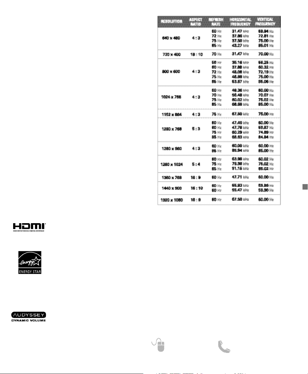
PC RESOLUTION CHART
FCC INFORMATION __________
This equipment has been tested and found to comply
with the limits for a Class B digital device, pursuant to
Part 15 of the FCC Rules. These limits are designed to
provide reasonable protection against harmful interference in a residential installation. This equipment generates, uses and can radiate radio frequency energy
and, if not installed and used in accordance with the
instructions, may cause harmful interference to radio
communications. However, there is no guarantee that
interference will not occur in a particular installation. If
this equipment does cause harmful interference to
radio or television reception, which can be determined
by turning the equipment off and on, the user is encouraged to try to correct the interference by one or more
of the following measures:
– Reorient or relocate the receiving antenna.
– Increase the separation between the equipment and
receiver.
– Connect the equipment into an outlet on a circuit dif-
ferent from that to which the receiver is connected.
– Consult the dealer or an experienced radio/TV tech-
nician for help.
CAUTION: FCC Regulations state that improper modifications or unauthorized changes to this unit may void
the user’s authority to operate the unit.
As an Energy Star® Partner, Sanyo
Manufacturing Corporation has
determined that this product meets
the Energy Star® guidelines for energy
efficiency.
TRADEMARKS _______________
Manufactured under license from Dolby Laboratories.
“Dolby” is a trademark of Dolby Laboratories.
HDMI, the HDMI Logo and HighDefinition Multimedia Interface are
trademarks or registered trademarks of
HDMI Licensing LLC in the United
States and other countries.
This Class B digital apparatus complies with Canadian
ICES-003.
Manufactured under license from
Audyssey Laboratories. U.S. and
foreign patents pending. Audyssey
Dynamic Volume
TM
is a trademark of
Audyssey Laboratories.
SPECIFICATIONS
Power Requirement: Source: AC 120V, 60Hz
AC Power Consumption: Weight:
DP42841 178 watts 33 lbs.
DP46841 178 watts 41 lbs.
Dimensions:
MODEL WIDTH HEIGHT DEPTH
DP42841 40.0 26.4 9.2
w/o stand 24.4 4.0
DP46841 43.9 29.4 10.6
w/o stand 26.6 4.6
NOTE: Dimensions are in inches
Page 4
4
Need help? www.sanyoctv.com 1-800-877-5032
CONTENTS
IMPORTANT SAFETY INSTRUCTIONS . . . . . . . . . . . . 2
FCC INFORMATION . . . . . . . . . . . . . . . . . . . . . . . . . . . .3
TRADEMARKS . . . . . . . . . . . . . . . . . . . . . . . . . . . . . . . .3
PC RESOLUTIONS . . . . . . . . . . . . . . . . . . . . . . . . . . . . .3
CONTENTS . . . . . . . . . . . . . . . . . . . . . . . . . . . . . . . . . . .3
SPECIFICATIONS . . . . . . . . . . . . . . . . . . . . . . . . . . . . . .4
PROTECTING THE LCD SCREEN . . . . . . . . . . . . . . . . .4
HANDLING PRECAUTIONS . . . . . . . . . . . . . . . . . . . . .4
POSITIONING THE LCD HDTV . . . . . . . . . . . . . . . . . . .4
STAND ASSEMBLY /STAND REMOVAL . . . . . . . . . . 5
WALL MOUNTING . . . . . . . . . . . . . . . . . . . . . . . . . . . . .5
GETTING STARTED—
Remote Control Battery Installation . . . . . . . . . . . .5
Antenna Connections for off-air or cable . . . . . . . .5
BACK PANEL JACKS . . . . . . . . . . . . . . . . . . . . . . . . . . .6
A/V CONNECTIONS . . . . . . . . . . . . . . . . . . . . . . . . . . . .7
REMOTE CONTROL OPERATION . . . . . . . . . . . . . . . . .8
POWER CONNECTION / INITIAL CHANNEL SEARCH 9
ON-SCREEN MENU OPERATION—
Channel Setting . . . . . . . . . . . . . . . . . . . . . . . . . . . . .9
Channel Search . . . . . . . . . . . . . . . . . . . . . . . . . .9
Channel Scan Memory . . . . . . . . . . . . . . . . . . . .9
Input Setting . . . . . . . . . . . . . . . . . . . . . . . . . . . .10
Video2 Setting . . . . . . . . . . . . . . . . . . . . . . . . . .10
Setup . . . . . . . . . . . . . . . . . . . . . . . . . . . . . . . . . . . .10
Menu Language . . . . . . . . . . . . . . . . . . . . . . . . .10
Digital Caption . . . . . . . . . . . . . . . . . . . . . . . . . .10
Energy Saver . . . . . . . . . . . . . . . . . . . . . . . . . . .10
Clock Timer . . . . . . . . . . . . . . . . . . . . . . . . . . . . .11
Light Sensor . . . . . . . . . . . . . . . . . . . . . . . . . . . .11
Auto Shut-off . . . . . . . . . . . . . . . . . . . . . . . . . . .11
V-Chip . . . . . . . . . . . . . . . . . . . . . . . . . . . . . . . . .11
Picture . . . . . . . . . . . . . . . . . . . . . . . . . . . . . . . . . . . .12
Manual Picture Settings . . . . . . . . . . . . . . . . . .12
Pix-Shape Settings . . . . . . . . . . . . . . . . . . . . . . .12
Sound . . . . . . . . . . . . . . . . . . . . . . . . . . . . . . . . . . . .13
aaManual Sound Settings . . . . . . . . . . . . . . . . . . .13
PHOTO VIEWER . . . . . . . . . . . . . . . . . . . . . . . . . . . . . .13
PC CONNECTIONS . . . . . . . . . . . . . . . . . . . . . . . . . . .14
PC MENU OPERATION . . . . . . . . . . . . . . . . . . . . . . . .14
WARRANTY . . . . . . . . . . . . . . . . . . . . . . . . . . . . . . . . .15
POSITIONING THE HDTV
•
Always use a firm and flat surface when positioning
your HDTV.
•
Do not position the unit in a confined area.
•
Allow adequate space for proper ventilation.
•
Do not position the HDTV where it is easily reachable
by small children and may present risk of injury.
•
Once HDTV is positioned, remove the protective film
covering the front cabinet.
NOTE: Button area on bottom right hand corner will be
more accesible once film is removed.
“The American Academy of Pediatrics discourages
television viewing for children younger than two years
of age”
PROTECTING THE LCD SCREEN
CAUTION: The screen can be damaged if it is not
maintained properly.
•
Do not use hard objects such as hard cloth or paper to
clean the screen.
•
Do not use excessive pressure when cleaning the
screen; excessive pressure can cause permanent
discoloration or dark spots.
•
NEVER spray liquids on the screen.
HANDLING PRECAUTIONS
•
Handle by the cabinet only.
•
Handling by two or more people is recommended.
•
Never touch the screen when handling.
•
Handling damage is not covered under warranty.
•
Do not remove the protective film covering the front
cabinet while handling the HDTV.
Please read before
operating your HDTV!
CONTAINS MERCURY LAMPS,
DISPOSE OF PROPERLY
Page 5
5
Need help? www.sanyoctv.com 1-800-877-5032
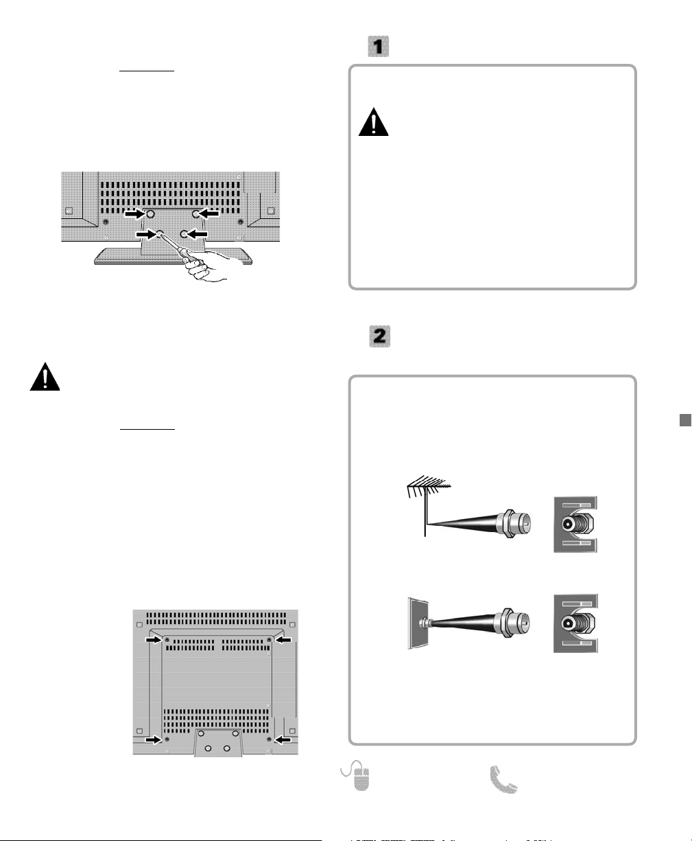
Hook up your antenna or your cable service to the
HDTV’s ANT terminal with the use of a 75 OHM
coaxial cable.
NOTE: Keep your indoor antenna at least 3 ft. away
from the television set and any other electronic
equipment.
The tuner in this HDTV can receive:
• Digital and Analog off air signals from an antenna
• Analog or ClearQAM cable channels from a direct
Cable TV connection.
GETTING STARTED
Install two (2) “AAA” batteries in the remote control.
(Not included)
To ensure safe operation, please observe
the following precautions:
• Replace both batteries at the same time. Do not use
a new battery with a used battery.
• There’s a risk of explosion if a battery is replaced by
an incorrect type.
• Do not expose the Remote Control unit to moisture
or heat.
• Be sure to match the “+” and “–” signs on the
batteries with marks inside the remote control.
• Please properly dispose of used up batteries.
ANTENNA CONNECTION FOR
OFF-AIR SIGNALS OR CABLE
ANTENNA
CABLE
ANALOG / DIGITAL
ANTENNA IN
BATTERY INSTALLATION
Wall mounting of the HDTV must be performed
by a skilled person.
If stand base disassembly is required:
1
Place HDTV face down
on a padded or cushioned
flat surface to protect the screen and finish.
2
Remove the four (4) screws securing the foot stand.
CAUTION: Hold the stand firmly as you remove the
last screw.
Use the screws you would use to attach the stand base
to secure the HDTV to a wall mounting kit.
NOTE: Wall mounting kit is not included.
VESA standard interface: 400 x 400
Mounting screws measurements:
M6 (6mm) Diameter, Length—12mm (maximum)
WALL MOUNTING (OPTIONAL)
Wall Mounting
Inserts
NOTE: Skip these steps if you are wall mounting the TV.
1
Place HDTV face down on a padded or cushioned
flat surface to protect the screen and finish.
2
Carefully insert the stand base to the bottom of the
HDTV and secure the base by inserting 4 screws as
indicated in the diagram below.
NOTE: Stand base screws are located in the literature
package.
3
Position the HDTV on a firm and flat surface with
adequate space for proper ventilation.
STAND ASSEMBLY ___________
Page 6
6
Need help? www.sanyoctv.com 1-800-877-5032
GETTING STARTED
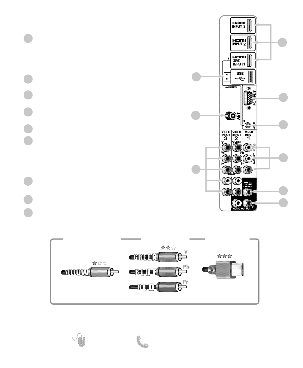
HDTV INPUT/OUTPUT REFERENCE
HDTV BACK PANEL
7
3
1
2
5
HDMI (INPUT1, INPUT2, & INPUT3)
An all digital AV interface that can accept uncompressed
video signals up to 1080p for the very best picture possible.
NOTE: A DVI connection is possible via the HDMI (DVI)
INPUT1 using an appropriate adapter and connecting
the audio signal to AUDIO mini stereo jack.
USB Input
View pictures stored in a USB flash drive.
PC Input
Monitor RGB (D-SUB)
AUDIO mini stereo jack (3.5mm)
For AUDIO signal from PC or DVI device.
Analog / Digital Antenna Input
Component AV Input (VIDEO2 or VIDEO3)
Green (Y), blue (Pb), and red (Pr) Video inputs plus the white
and red Audio inputs.
NOTE: A composite connection is possible via VIDEO INPUT2
using the Y (VIDEO) jack and the L/R audio jacks. (See
Video2 Setting on page 11.)
Composite AV Input (VIDEO1)
Yellow (Video), plus white and red (Audio) input jacks.
Digital Audio Output (Coaxial)
Analog Stereo Audio Out (L/R) Jacks
1
2
3
4
5
6
7
8
6
Composite
Component
NOTE: Composite, Component, and DVI video connections need their appropriate audio connections.
High Definition image available from HD signals and HD equipment.
Standard Definition
High Definition
Optimum
High Definition
H D M I
(or DVI to HDMI
cable/adapter)
9
8
4
9
Page 7
7
Need help? www.sanyoctv.com 1-800-877-5032
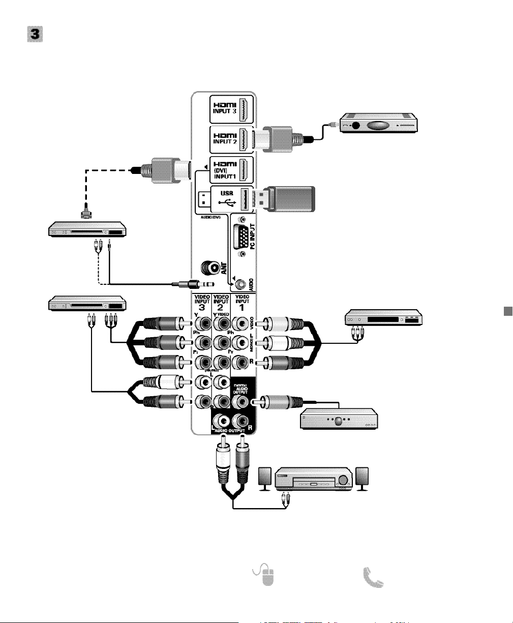
GETTING STARTED
AUDIO / VIDEO CONNECTIONS
DVD PLAYER
(or similar device)
VCR
(or analog device)
MULTICHANNEL
RECEIVER
NOTE: Audio/Video cables
are not supplied
COMPONENT connections will accept
SDTV, EDTV and HDTV video signals. Use
them for great image quality from digital
devices such as a DVD player or Video
Game system.
Match your digital device’s Component
output jacks to either of the two (2)
Component input jack sets (VIDEO2 or
VIDEO3) on your HDTV.
SATELLITE RECEIVER
(or similar device)
USB FLASH
DRIVE
HDMI (DVI) INPUT1 can be used to
hookup a DVI device with the use of an
appropriate DVI to HDMI cable or adapter.
Stereo Mini AUDIO jack needs to be
hooked up to the DVI device as well
NOTE: HDMI INPUT1 may also be used to
hookup any digital device with an
HDMI output, without the use of the
Stereo Mini AUDIO jack.
USB input jack is used to connect a USB mass storage device
to watch digital images stored in
JPEG format.
DVI
Use HDMI INPUT1, 2 & 3 to hookup HD digital devices
such as a Blu-ray player, HD Cable Box, HD Satellite
Receiver or Video-game System.
Connect your digital device’s HDMI output to any of
the three (3) HDMI inputs on your HDTV with the use
of an HDMI cable.
Audio Output L/R are used to hookup an external
stereo Amplifier. (Do not connect external speakers
directly to the HDTV)
STEREO
AMPLIFIER
COMPOSITE connections are used to hookup your
analog equipment such as a VCR or an older DVD
player.
NOTE: Match the color of your device’s output jack,
the connector and the HDTV’s input jack.
Digital Audio Output is used to
hookup a multichannel receiver
with the use of a phono-type
digital audio cable.
DVD PLAYER
(or similar device)
Page 8
8
Need help? www.sanyoctv.com 1-800-877-5032
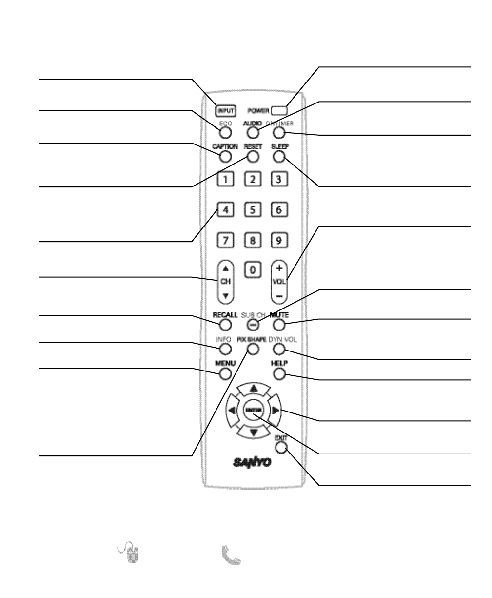
REMOTE CONTROL OPERATION
Turns your HDTV On or Off.
Selects the video source to view. Holding
down the key displays the Input List.
Modifies the Energy Saver level (see page
10 for details.)
Selects the desired Audio mode.
Stereo, Mono, or SAP (when available.)
Displays the current switch on time (see
Clock Timer on page 10 for details.)
Cycles through the available Caption
modes (when available.)
Pressing it twice restores your HDTV to its
factory settings. All user customized settings will be cleared.
Displays the “Off” Timer. While Off Timer
is on-screen, press the “0” key to Set the
amount of time (in 30 minute increments)
at which the HDTV will turn off.
Select channels directly.
For channels 100 and up, press and hold
the first number, then enter the remaining
two numbers.
Scan through the channels in the memory
database.
Increases or decreases the audio level.
Allows for the direct selection of digital
subchannels. For example: to select
channel 39.1 press the 3 and 9 keys,
followed by the dash ––, and 1 keys.
Switch between current channel and last
selected channel or input.
Mute or restore the sound.
Displays the Channel Information banner.
Cycles through the available aspect
ratios. The different settings either
stretch, zoom, or fill the image on your
screen. Bars may appear on top and bottom of your screen (or on left and right
sides) depending on the broadcasted signal or program. (See page 15)
Modifies the Dynamic Volume feature
settings (see page 13 for details.)
Displays on-screen Help menu.
Displays or hides the on-screen menu.
Move the on-screen cursor in the
desired direction.
Set or select the highlighted option on
the screen.
Exits the on-screen menu.
Page 9
9
Need help? www.sanyoctv.com 1-800-877-5032
1. PLUG IN AC POWER CORD
120V AC, 60Hz
2. TURN ON TV (PRESS POWER BUTTON)
Wait for on-screen instructions to set an Initial Energy
Saving Mode, and perform an Initial Channel/Signal
Search.
3. TV SET LOCATION SELECTION:
Select “Home Mode” by pressing the CH key to set
the HDTV’s backlight to an Energy Star qualified
level, or select “Store Mode” by pressing CH to set
the backlight to a retail display level.
4. CHANNEL AND AV SIGNAL SEARCH:
Press the CH key to perform a channel search
from an Antenna or a direct Cable connection,
followed by a signal search from devices hooked up
to the HDTV’s AV input jacks.
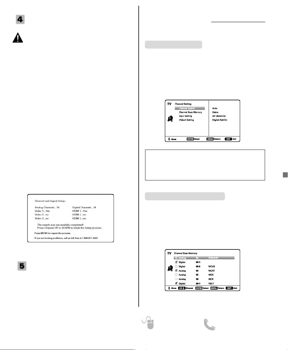
5. CHANNEL AND SIGNAL SETUP SCREEN
The final setup screen displays analog and digital
channels found as well as AV inputs detected.
Pressing the CH key finalizes the setup process.
NOTE: To repeat the initial setup process press
the MENU key.
GETTING STARTED (CONTINUED)
INITIAL CHANNEL SEARCH
Before proceeding, please make sure to correctly
hook up your antenna or cable connection and all
AV equipment to your HDTV.
AV INPUT SELECTION
Press the INPUT key to select the correct AV input for the
video source you wish to watch.
NOTE: Unused AV inputs may be disabled with the Input
Setting feature (see page 10).
CHANNEL SETTING
Auto – Searches the detected mode, Cable or Air.
Cable – Searches for analog and unscrambled
(ClearQAM) digital cable channels.
Air (Antenna) – Searches for analog and digital off-air
channels.
Digital Add-On – Searches digital channels adding newly
found digital channels to the channel database.
Channel Search
Display the On Screen menu and use the CURSOR
keys to select Channel Setting. Press ENTER.
ON-SCREEN MENU OPERATION
Channel Scan Memory lists all Analog and Digital channels found. It also lists Analog channels that were not
found, which can be added.
Use the CURSOR keys to move the channel select
bar through all enabled and disabled channels, or use
the CH keys to skip all disabled channels.
Press ENTER to enable or disable the selected channel.
NOTE: For information on local digital channels, visit
www.antennaweb.org
Channel Scan Memory
IMPORTANT FACT: This HDTV maintains only one database of
digital channels. Therefore, when you search for cable channels,
the database of antenna digital channels will be deleted. You will
only be able to receive those ClearQAM channels your cable
company provides.
Page 10

10
Need help? www.sanyoctv.com 1-800-877-5032
CHANNEL SETTING (CONTINUED)
ON-SCREEN MENU OPERATION
Input Setting feature allows the removal of unused
inputs from the AV input loop.
Use the CURSOR keys to select an AV input. Press
ENTER to disable (uncheck) or enable (check) the highlighted input.
NOTE: At least one input must and will remain checked.
:Skip is for reference only.
Input Setting
Use this feature to establish either a Component or
Composite connection to the VIDEO INPUT 2 jacks on
your HDTV.
Use the CURSOR keys to select the type of connection you’ll use in VIDEO INPUT 2.
Press ENTER, a blue mark will appear next to the
selected option indicating it as the active option.
Video2 Setting
SETUP
Display the On Screen menu and use the CURSOR
keys to select Setup. Press ENTER.
Menu Language
Choose between English, Spanish and French for your
On Screen menu’s display language.
Press ENTER on the desired language.
Captioning is textual information transmitted along with
the picture and sound. Turning Captioning ON (by
pressing the CAPTION key during normal TV viewing)
causes the HDTV to open these captions (digital or
analog) and superimpose them on the screen.
NOTE: Local broadcasters decide which caption signals
to transmit.
Use the CURSOR and keys to modify Font,
Background, and Foreground of digital caption text.
Digital Caption
Energy Saver settings control the LCD backlight
brightness to reduce power consumption.
• Level 1: Energy Saver feature is off.
• Level 2: Low power consumption.
• Level 3: Lowest power consumption.
Press ENTER on the desired level.
NOTE: ECO key may also be used as a shortcut to
modify the Energy Saver settings.
Energy Saver
This feature allows you to set a Current Time for your
HDTV and enable a Switch On Time for the HDTV to
turn on at a specific time of day.
When On Timer Function is set to ON, the TV will
automatically turn on at the previously set Switch on
Time.
Clock Timer
Page 11
11
Need help? www.sanyoctv.com 1-800-877-5032
This feature detects ambient room light brightness and
uses that reading to control the panel brightness level
and picture parameters to reduce the HDTV’s power
consumption.
NOTE: When room lighting is dark, the panel bright-
ness and/or the picture setting parameters such
as brightness and contrast are lowered. When
room lighting is bright, parameters are affected
opposite.
Use the CURSOR keys to select On or OFF and
press ENTER.
Light Sensor
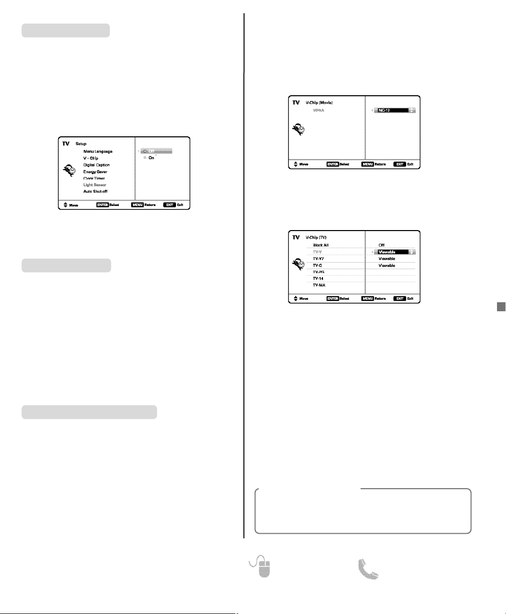
Use this feature to automatically block programs with
content you deem as inappropriate for viewing by your
children.
NOTE: This feature is designed to comply with the
United States of America’s FCC V-Chip regulations. Therefore, it may not function with broadcasts that originate in other countries.
ADJUSTING THE V-CHIP RATINGS
Select ON and press ENTER. Select Adjust (Standard)
and press ENTER.
V-Chip (parental control)
NOTE: Blocking a rating will automatically block all
higher ratings. Unblocking a rating will automatically unblock all lower ratings.
For V-Chip (Movie) ratings select Movie and press
ENTER, and then select the desired MPAA rating limit.
Press the EXIT key to close the V-Chip menu.
For V-Chip (TV) ratings select TV and press ENTER. Use
the CURSOR keys to select a rating and press
ENTER. Use the CURSOR keys to set the rating’s
status as Blocked or Viewable. Once ratings are set,
press the EXIT key to close the V-Chip menu.
NOTE: Some TV ratings offer more detailed settings
such as Dialogue, Language, Sexual, and
Violence.
ADVANCED V-CHIP SYSTEM (RRT5)
RRT5 (V-Chip Regional Ratings 5) is an advanced V-Chip
ratings system for over the air digital channels. When the
HDTV detects compatible RRT5 data, it’s downloaded &
stored in memory, and the Setup V-Chip screen is then
modified to show the Adjust (Advanced) option.
Use the CURSOR and keys to highlight the
different options, and use the ENTER key to block or
unblock the selected rating.
NOTE: When vertical scroll bars appear, press
CURSOR
to gain access to the additional ratings.
MORE INFORMATION
Additional information about MPAA (Motion Picture
Association of America) and V-Chip rating can be
found at: www.mpaa.org and www.v-chip.org,
respectively.
When Auto Shut-off feature is set to ON, it will allow
the HDTV to automatically turn off when no video
and/or audio signals are being received.
NOTES: By factory default, this feature is set to ON.
TV will automatically turn off if no AV signals
are received in a time span of 15 minutes.
Use the CURSOR keys to select On or OFF and
press ENTER.
Auto Shut-off
Page 12
12
Need help? www.sanyoctv.com 1-800-877-5032
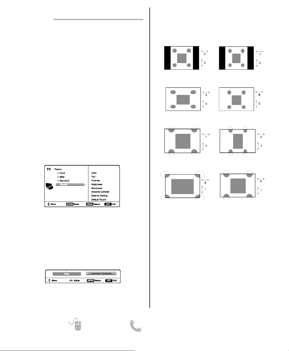
Pix1 Shows a standard definition 4:3 image in its
original format, a 16:9 wide image is slightly
compressed horizontally.
Pix2 Fills the entire image on the screen. A 4:3 image
is slightly stretched horizontally.
Pix3 Image is stretched vertically in comparison with
Pix2.
Pix4 Image is stretched horizontally in comparison
with Pix3.
Pix5 Similar to Pix2, image is enlarged horizontally
but in a linear proportion in which center portion
of screen is stretched less than the sides.
Pix6 Similar to Pix1 with no Overscan*.
Pix7 Similar to Pix2 with no Overscan*.
* Overscan permits the image to slightly exceed bot-
tom and top edge limitations.
NOTE: Pix6 and Pix7 are not optimal for Standard
Definition content (a thin white line may appear
near edge of screen). Pix6 and Pix7 use is recommended only for PC signal through HDMI.
Pix-Auto (AFD) Active Format Description.
Data carried in the video stream includes coded picture
frame information of the actual image, allowing the TV
to adjust the Pix-Shape automatically.
NOTE: AFD Pix-Shape mode is available only for Digital-
RF input.
UNDERSTANDING PIX-SHAPE
PICTURE
ON-SCREEN MENU OPERATION
Display the On Screen menu and use the CURSOR
keys to select Picture. Press ENTER.
You may choose between Vivid, Mild, and Standard,
which have predetermined fixed picture parameter
values, or choose the Manual option for customized
personal settings.
NOTE: Each AV input can have its own picture mode
(pre-determined or manual.) Current input’s
selected option is indicated by a blue marker.
MANUAL PICTURE SETTINGS
Manual parameters to adjust include:
•
Color
•
Tint
•
Contrast
•
Brightness • Sharpness• Dynamic Contrast
The Detailed Setting option allows for the adjustment
of 7 additional parameters such as:
•
Signal Balancer• Noise Reduction
•
White Balance• Vertical Sharpness
•
Edge Enhancer• H-Size • V-Size
NOTE: Default Picture option returns all picture parame-
ters to their original factory settings.
ADJUSTING A PICTURE SETTING
Use the CURSOR keys to highlight the picture parameter you wish to adjust. Press the ENTER key to enter the
value adjustment screen. Modify the selected parameter’s
value by pressing the CURSOR keys.
NOTE: CURSOR keys select the next/previous
parameter without returning to the previous
menu screen.
Once adjustments are complete, press the EXIT key to
return to normal TV viewing.
NOTE: Images on left are for a 4:3 transmission while
images on right are for a 16:9 transmission.
Page 13
13
Need help? www.sanyoctv.com 1-800-877-5032
SOUND
ON-SCREEN MENU OPERATION
Display the On Screen menu and use the CURSOR
keys to select Sound. Press ENTER.
Choose an option for your sound settings:
Auto – Sound settings are linked to the current Picture
option and parameters are adjusted accordingly.
Dynamic, Mild, Standard – Predetermined sound
parameters not linked with any Picture option.
MANUAL SOUND SETTINGS
The Manual option provides different parameters that
can be personally adjusted:
•
Bass & Treble • Bass Extension
•
Audyssey Dynamic Volume
1
•
Detailed Setting
– 4-Band Equalizer: Personalize audio highs and lows.
NOTE: Default Sound option returns all sound parame-
ters to their original factory settings.
1
Audyssey Dynamic Volume solves the problem of large variations in volume level between television programs, commercials,
and between the soft and loud passages of movies. Audyssey
Dynamic EQ is integrated into Dynamic Volume so that as the playback volume is adjusted automatically, the perceived bass
response, tonal balance, surround impression and dialog clarity
remain the same.
ADJUSTING A SOUND SETTING
Use the CURSOR keys to highlight the sound parameter you wish to adjust. Press the ENTER key to enter the
value adjustment screen. Modify the selected parameter’s
value by pressing the CURSOR keys.
NOTE: CURSOR keys select the next/previous
parameter without returning to the previous
menu screen.
Once adjustments are complete, press the EXIT key to
return to normal TV viewing.
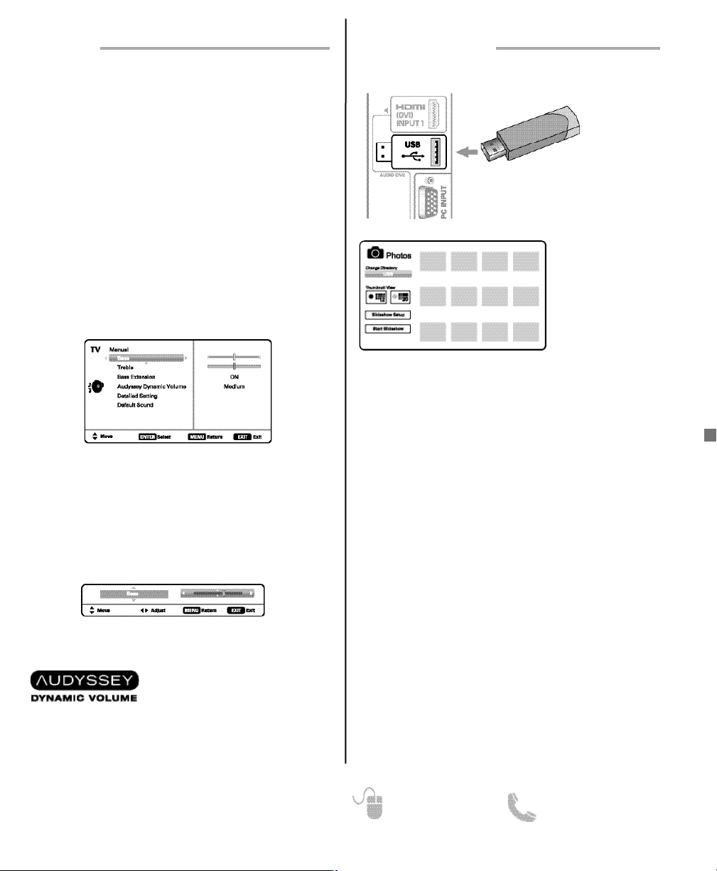
USING THE PHOTO VIEWER
Press ENTER on a thumbnail photo to enable the Rotate,
Full View and Start Slideshow functions.
Once in Full View mode:
Use the CURSOR keys to change picture.
Press ENTER to show the full view options menu.
•
Rotate
•
Zoom In
•
Zoom Out
•
Pan
•
Slideshow Setup• Browse Photo
SLIDE SHOW
In the Slideshow Setup menu you may turn the Shuffle
and Quick Change options ON or OFF.
Press ENTER on Start Slideshow either from the
Thumbnail View Screen or from the full view options
menu to start the slideshow from the current picture.
JPEG VIEWER USB MENU
Press MENU when in Full View or Slideshow mode to
display the USB On screen menu.
Picture Setting – Adjust Color, Tint, Contrast, Brightness,
Sharpness and Dynamic Contrast.
NOTE: Picture Settings are separate configurations from
the settings in TV and AV inputs.
NOTE: A thumbnail
hide icon will appear
if a picture cannot be
decoded or if no
thumbnail data is
available.
View pictures on your HDTV with the use of a USB mass
storage device (not included.)
NOTE: The HDTV switches to
USB Input when a USB
flash drive is detected.
USB FLASH
DRIVE
PHOTO VIEWER
USB INPUT
Page 14
14
Need help? www.sanyoctv.com 1-800-877-5032
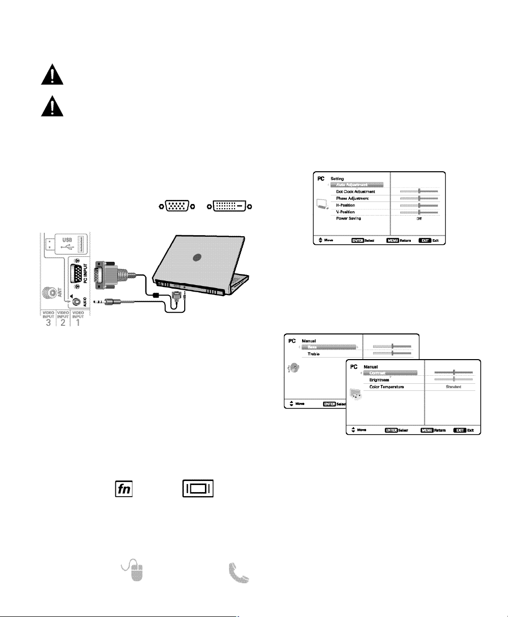
PC Setting
Auto Adjustment – Automatically adjusts display posi-
tion, dot clock and phase.
Dot Clock – Adjust the Dot frequency to match your
computer’s Dot frequency.
Phase – Adjust this parameter when the picture appears
to flicker or is blurred.
H-Position – Move the image horizontally
V-Position – Move the image vertically
Power Saving – Enable the HDTV to turn to Standby
Mode when computer is not in use.
PC Picture and Sound
Standard – Sets predetermined values to the Picture or
Sound parameters.
Manual – Adjust Contrast, Brightness, and Color
Temperature screen settings, and the Bass
and Treble audio settings.
NOTE: These settings do not affect normal TV viewing.
Laptop Display
When using your Sanyo HDTV to display a Laptop’s
screen display, holding down the Fn (or FN) key while
pressing the appropriate function key (F5, F7, F8, etc)
should cycle through different display modes between
the laptop and the HDTV.
Modes may include displaying only on the laptop
screen, on both the laptop and the HDTV, or
displaying only on the HDTV.
NOTE: Fn key and function key symbols on the laptop’s
keyboard may vary from one brand to another.
Hold down and press
PC OR LAPTOP
HDTV BACK
RGB Monitor
cable
Stereo mini
audio cable
NOTE: Sanyo recommends using a monitor cable that
includes a Ferrite Core.
DVI OUTPUT
JACK
RGB OUTPUT
JACK
Use your HDTV as a computer monitor by hooking up
your PC or Laptop to the TV with the use of an appropriate monitor cable (not included.)
Before connecting any cables, disconnect the AC
power cords of both the HDTV and PC from the
AC outlets.
Power on the HDTV and any other peripheral
equipment before powering on the computer.
To avoid an “Out of Range” condition please set your
PC’s output resolution to one compatible with your
HDTV. See PC Resolution chart on page 3.
NOTE: If computer has only DVI Output, a DVI to RGB
adapter will be required, or, a DVI to HDMI cable and
RCA audio cables (see HDMI (DVI) INPUT1 on page 7.)
PC INPUT
Page 15

15
Need help? www.sanyoctv.com 1-800-877-5032
Your Sanyo HDTV is registered at the time of purchase, please keep sales receipt for future reference.
For your protection in the event of theft or loss of this product, please fill in the information requested
below and KEEP IN A SAFE PLACE FOR YOUR OWN PERSONAL RECORDS.
Model No.______________________________ Date of Purchase _________________________
Serial No.______________________________ Purchase Price ___________________________
Where Purchased_________________________
(Located on back of unit)
Sanyo Manufacturing Corp.
3333 Sanyo Road, Forrest City, AR 72335
ONE-YEAR LIMITED PARTS AND LABOR WARRANTY
THIS LIMITED PARTS AND LABOR WARRANTY IS VALID ONLY ON SANYO TELEVISIONS PURCHASED AND USED IN
THE UNITED STATES OF AMERICA, CANADA, AND PUERTO RICO, EXCLUDING ALL OTHER U.S. TERRITORIES AND
PROTECTORATES. THIS LIMITED WARRANTY APPLIES ONLY TO THE ORIGINAL RETAIL PURCHASER, AND DOES NOT
APPLY TO PRODUCTS USED FOR INDUSTRIAL OR COMMERCIAL PURPOSES.
WARRANTY APPLICATION
FOR ONE YEAR from the date of original retail purchase Sanyo Manufacturing Corporation (SMC) warrants this TV to
be free from manufacturing defects in materials and workmanship under normal use and conditions for parts and labor.
For the FIRST 90 DAYS from the date of original retail purchase, Sanyo Manufacturing Corporation will replace any
defective TV via exchange at the retailer. To ensure proper warranty application, keep the original-dated-sales receipt
for evidence of purchase. Return the defective TV to the retailer along with the receipt and the included accessories,
such as the remote control. The defective TV will be exchanged for the same model, or a replacement model of equal
value, if necessary. Replacement model will be contingent on availability and at the sole discretion of Sanyo
Manufacturing Corporation.
THE FOREGOING WARRANTY IS EXCLUSIVE AND IN LIEU OF ALL OTHER WARRANTIES OF MERCHANTABILITY OR
FITNESS FOR A PARTICULAR PURPOSE.
OBLIGATIONS
For one year
from the date of purchase, Sanyo Manufacturing Corporation warrants this product to be free from
defects in material and workmanship under normal use and conditions. During the first 90 days
under this warranty
for any manufacturing defect or malfunction Sanyo Manufacturing Corporation will provide a new TV via exchange at
the retailer.
HOW TO MAKE A CLAIM UNDER THIS WARRANTY
Please call 1-800-877-5032. Please be prepared to give us the television’s model number and serial number when you
call. The model number and serial number are printed on a label attached to the back of the unit.
For customer assistance, call toll free 1-800-877-5032.
This warranty expresses specific contractual rights; retail purchasers may have additional statutory rights which vary
from state to state.
(EFFECTIVE: March 1, 2007)
Page 16

16
¿Necesita ayuda? www.sanyoctv.com 1-800-877-5032
PRECAUCIÓN
RIESGO DE CHOQUE ELÉCTRICO ¡NO ABRIR!
PRECAUCIÓN: PARA REDUCIR EL RIESGO DE CHOQUE ELÉCTRICO, NO QUITE LA CUBIERTA
(O LA TAPA TRASERA). NO HAY PARTES ADENTRO QUE LAS PUEDA REPARAR EL USUARIO.
REFIÉRASE A PERSONAL CALIFICADO PARA REPARAR EL APARATO.
ESTE SÍMBOLO INDICA QUÉ VOLTAJES PELIGROSOS QUE CONSTITUYEN UN RIESGO DE CHOQUE ELÉCTRICO ESTÁN PRESENTES DENTRO DE ESTA UNIDAD.
ESTE SÍMBOLO INDICA QUE HAY INSTRUCCIONES IMPORTANTES DE
OPERACIÓN Y MANTENIMIENTO EN LA LITERATURA QUE SE ANEXA A
ESTA UNIDAD.
ADVERTENCIA: PARA REDUCIR EL RIESGO DE FUEGO O CHOQUE ELÉCTRICO, NO EXPONGA ESTE
APARATO A LLUVIA O HUMEDAD.
IMPORTANTES MEDIDAS DE SEGURIDAD
1. Lea estas instrucciones.
2. Guarde estas instrucciones.
3. Preste atención a los avisos.
4. Siga todas las instrucciones.
5. No use este aparato cerca del agua.
6. Limpie sólo con un trapo seco.
7. No obstruya las aperturas para ventilación. Instale de
acuerdo a las instrucciones del fabricante.
8. No se instale cerca de ninguna fuente de calor como
radiadores, registros de calor, estufas, u otros aparatos
(incluyendo amplificadores) que produzcan calor.
9. Por seguridad, no elimine la conexión de tierra de la
clavija. Una clavija polarizada tiene una hoja más ancha
que la otra. Una clavija de tipo conexión a tierra, tiene dos
hojas y un tercer conector mas prolongado. La hoja ancha
o el conector prolongado están provistas para su seguridad. Si la clavija proveída no asienta correctamente en el
contacto eléctrico, consulte a un electricista para que esa
toma de ac obsoleta sea remplazada.
10. Proteja el cordón de potencia de que sea pisado o
perforado, particularmente en las hojas y del punto donde
éste sale del aparato.
11. Sólo use anexos o accesorios especificados por el
fabricante.
12. Use únicamente con el carro, estante, tripie,
soporte o mesa especificada por el fabricante, o
vendida con el aparato. Cuando se use un carro,
tenga precaución cuando mueva la combinación
de carro/aparato para evitar lesiones en caso de
que se caiga.
13. Desconecte este aparato en caso de tormenta eléctrica o
cuando no se use por un periodo de tiempo prolongado.
14. Refiera todas las reparaciones a personal de servicio calificado. Se requiere de servicio cuando el aparato se ha dañado de cualquier forma, como si el cordón de potencia se
dañara de alguna forma, se ha derramado líquido sobre el
aparato o algún objeto le ha caído encima, el aparato se ha
expuesto a la lluvia o humedad, que no opere normalmente
o que se haya caído.
15. Si una antena externa se ha conectado al televisor,
asegúrese que el sistema de tierra de la antena esté de
forma que provea alguna protección contra fugas de voltaje o cargas electrostáticas. En la sección 810-21 del código
eléctrico nacional de los Estados Unidos se menciona información con respecto a la manera adecuada de instalar el
sistema de tierra al mástil principal, aterrizaje del cableado
para la unidad de descarga de la antena, tamaño de los conductores de tierra, localización de la unidad de descarga
de la antena, conexión a los electrodos de tierra, y
requerimientos de los electrodos de tierra.
16. Un sistema de antena externo no debe instalarse cerca de
líneas de electricidad o circuitos de potencia o alumbrado, o
donde puedan caer sobre líneas de energía eléctrica o
circuitos cuyo contacto con ellos puede ser fatal.
17. Montaje en pared o techo—Este producto deberá de ser
montado en la pared o techo siguiendo las recomendaciones
del fabricante.
18. Este aparato no deberá de ser expuesto a ser mojado, y no
se deberán de colocar recipientes con líquido encima de él.
19. Si el conector del cable de AC se usa como artículo de
desconexión principal, entonces éste deberá de
permanecer accessible todo el tiempo.
EJEMPLO DE ATERRIZAMIENTO DE ANTENA DE ACUERDO
AL CÓDIGO ELÉCTRICO NACIONAL
(National Electrical Code, ANSI/NFPA 70)
“Nota al instalador del sistema de cable CATV :
Este recordatorio es dado para llamar la atención del instalador
del sistema de cable CATV al Artículo 820-40 del NEC que
provee guías para el aterrizamiento adecuado y, en particular,
especifica que el cable de tierra deberá de estar conectado al
sistema de tierra del edificio, tan cercano al punto de entrada
del cable como sea práctico.”
Page 17

17
¿Necesita ayuda? www.sanyoctv.com 1-800-877-5032
INFORMACIÓN FCC
Este equipo ha sido probado y se encontró en acuerdo
a los límites para un aparato digital Clase B, en acorde
a la Parte 15 de las Reglas FCC. Estos límites están diseñados para proveer una protección razonable contra
interferencia nociva en una instalación residencial. Este
equipo genera, usa y puede irradiar energía de radio
frecuencia y si no es instalado o usado de acuerdo a las
instrucciones, puede llegar a causar interferencia nociva a radio comunicaciones. Sin embargo, no es completamente seguro que no ocurrirá interferencia alguna en
una instalación en particular. Si este equipo llega a
causar interferencia nociva a la recepción de radio o
televisión, la cual puede ser determinada por medio de
apagar y encender el equipo, se recomienda al usuario
intentar corregir la interferencia mediante una o varias
de las siguientes medidas:
- Reorientar o mover la antena de recepción.
- Aumentar la separación entre el equipo y el receptor.
- Conectar el equipo a un enchufe en un circuito diferente al cual esté conectado el receptor.
- Consultar al vendedor o a un técnico de radio y televisión con experiencia para más ayuda.
PRECAUCIÓN: Regulaciones de la FCC advierten que
modificaciones inadecuadas o cambios no autorizados
a esta unidad pueden anular la autorización del usuario
para operar la unidad.
RESOLUCIONES DE PC
MARCAS REGISTRADAS
Manufacturado bajo licencia de Dolby Laboratories.
“Dolby ” es una marca registrada de Laboratorios
Dolby.
Manufacturado bajo licencia de
Audyssey Laboratories. Patentes de
E.U.A. y foráneas pendientes.
Audyssey Dynamic Volume
TM
es una
marca de Audyssey Laboratories.
HDMI, el logo HDMI y “High-Definition
Multimedia Interface” son marcas registradas de HDMI Licensing LLC en los
Estados Unidos y otros países.
Como un Asociado de ENERGY STAR®,
Sanyo Manufacturing Corporation, ha
determinado que este producto cumple
con los lineamientos en eficiencia
energética de ENERGY STAR®.
ESPECIFICACIONES
Requerimiento de Potencia: AC 120V, 60Hz
Consumo de Potencia: Peso:
DP42841 178 watts 15 kg.
DP46841 178 watts 18 kg.
Dimensiones:
MODELO ANCHO ALTO PROFUNDO
DP42841 101,8 67,1 23,5
sin base 61,9 10,2
DP46841 111,5 74,6 27,0
sin base 67,6 11,6
NOTA: Las dimensiones están en centímetros.
Page 18

18
¿Necesita ayuda? www.sanyoctv.com 1-800-877-5032
PROTEGER LA PANTALLA LCD
PRECAUCIÓN: La pantalla podría dañarse si no se le da
un mantenimiento adecuado.
• NO use objetos duros como trapos gruesos o papel
para limpiar la pantalla.
• NO utilice presión excesiva cuando se limpie la
pantalla de LCD; esto podría causar decoloración
permanente o puntos negros en la misma.
• NUNCA aplique líquidos en aerosol a la pantalla.
PRECAUCIONES DE
MANEJO
• Manéjese sólo por el gabinete.
• Se recomienda manejar el televisor por dos o más
personas.
• Nunca toque la pantalla cuando esté manejando la
HDTV.
• Daño por manejo no está cubierto por la garantía.
• No remueva la cinta protectora que cubre el gabinete
mientras maneje la HDTV.
IMPORTANTES MEDIDAS DE SEGURIDAD . . . . . . .16
INFORMACIÓN FCC . . . . . . . . . . . . . . . . . . . . . . . . . . .17
MARCAS REGISTRADAS . . . . . . . . . . . . . . . . . . . . . .17
RESOLUCIONES DE PC . . . . . . . . . . . . . . . . . . . . . . . .17
CONTENIDO . . . . . . . . . . . . . . . . . . . . . . . . . . . . . . . . .18
PRECAUCIONES DE DESECHO . . . . . . . . . . . . . . . . .18
ESPECIFICACIONES . . . . . . . . . . . . . . . . . . . . . . . . . .18
PRECAUCIONES DE MANEJO Y PANTALLA . . . . . .18
COLOCACIÓN DE LA HDTV . . . . . . . . . . . . . . . . . . . .18
PONER LA BASE / MONTAJE EN PARED . . . . . . . . .19
PARA COMENZAR—
Instalación de baterías al control . . . . . . . . . . . . . .19
Conexión de antena aire/cable . . . . . . . . . . . . . . . .19
CONECTORES DEL PANEL TRASERO . . . . . . . . . . . .20
CONEXIONES DE AUDIO/VIDEO . . . . . . . . . . . . . . . .21
OPERACIÓN DEL CONTROL REMOTO . . . . . . . . . . .22
BÚSQUEDA INICIAL DE CANALES . . . . . . . . . . . . . .23
OPERACIÓN DEL MENÚ EN PANTALLA—
Establecer canales . . . . . . . . . . . . . . . . . . . . . . . . . .23
Búsqueda de canales . . . . . . . . . . . . . . . . . . . . .23
Memoria de canales . . . . . . . . . . . . . . . . . . . . .23
Establecer entradas . . . . . . . . . . . . . . . . . . . . . .24
Configuración de Video2 . . . . . . . . . . . . . . . . . .24
Configuración . . . . . . . . . . . . . . . . . . . . . . . . . . . . .24
Lenguaje del menú . . . . . . . . . . . . . . . . . . . . . .24
Subtítulos digitales . . . . . . . . . . . . . . . . . . . . . .24
Ahorrador de energía . . . . . . . . . . . . . . . . . . . .24
Reloj temporizador . . . . . . . . . . . . . . . . . . . . . .25
Sensor de luz . . . . . . . . . . . . . . . . . . . . . . . . . . .25
Apagado automático . . . . . . . . . . . . . . . . . . . . .25
V-Chip . . . . . . . . . . . . . . . . . . . . . . . . . . . . . . . . .25
Imagen . . . . . . . . . . . . . . . . . . . . . . . . . . . . . . . . . . .26
Configuración manual de imagen . . . . . . . . . .26
Configuración de Pix-Shape . . . . . . . . . . . . . . .26
Sonido . . . . . . . . . . . . . . . . . . . . . . . . . . . . . . . . . . .27
aaConfiguración manual de sonido . . . . . . . . . . .27
REPRODUCTOR DE IMÁGENES . . . . . . . . . . . . . . . . .27
CONEXIONES DE PC . . . . . . . . . . . . . . . . . . . . . . . . . .28
CONFIGURACIÓN DE PC . . . . . . . . . . . . . . . . . . . . . .28
GARANTÍA . . . . . . . . . . . . . . . . . . . . . . . . . . . . . . . . . .29
Favor de leer antes de
operar su HDTV!
CONTIENE LÁMPARAS DE
MERCURIO, DESECHAR
DE MANERA APROPIADA
“La Academia Americana de Pediatras no recomienda
permitir a niños menores de 2 años ver televisión”
COLOCANDO LA HDTV
• Siempre utilice una superficie firme y plana al colocar
su HDTV.
• No se coloque la HDTV en áreas confinadas.
• Mantenga suficiente espacio alrededor de la HDTV
para una buena ventilación.
• No coloque la HDTV donde sea fácilmente
accessible a niños pequeños y pueda presentar un
riesgo de accidente.
• Ya posicionada la HDTV, remueva la cinta protectora
que cubre el gabinete.
NOTE: La botonera en la esquina inferior derecha será
más accesible al quitar la cinta.
CONTENIDO
Page 19

19
¿Necesita ayuda? www.sanyoctv.com 1-800-877-5032
Una persona con experiencia debe realizar el
montaje en pared.
Si requiere quitar la base:
1
Coloque la HDTV con la pantalla hacia abajo sobre
una superficie plana y acolchonada para proteger la
pantalla y el acabado de la HDTV.
2
Quite los cuatro (4) tornillos del pedestal de
soporte. PRECAUCIÓN: Sujete firmemente la base
al quitar el último tornillo.
Para asegurar la HDTV a un kit de montaje en pared,
utilice los tornillos que usaría para ensamblar la base.
(Kit no incluído)
Interfase estándar VESA: 400 x 400
Medida de los tornillos:
Diámetro M6, Longitud – 12mm (máximo)
INSTALACIÓN DE BATERÍAS
Instale las baterías al control remoto.
( 2 “AAA”, no incluídas)
Para una operación segura, favor de observar
las siguientes precauciones:
• Reemplace ambas baterías al mismo tiempo.
No utilice una batería nueva con una usada.
• Existe riesgo de explosión si las baterías son
remplazadas con unas de tipo incorrecto.
• No exponga el Control Remoto a calor o humedad.
• Asegúrese que las marcas “+” y “–” de las baterías
correspondan con las del control remoto.
• Deshágase apropiadamente de baterías gastadas.
Conecte su antena o servicio de cable a la entrada
ANT de su HDTV utilizando un cable coaxial (75
OHM).
NOTA: Mantenga su antena para interiores al menos
a un (1) metro de distancia tanto de su HDTV
como de cualquier otro aparato electrónico.
Esta HDTV puede sintonizar:
• Señales aéreas digitales y análogas de una antena.
• Canales de Cable análogos o sin codificar de una
conexión directa de TV por Cable.
CONEXIÓN DE ANTENA PARA
SEÑALES DE AIRE O CABLE
CABLE
ENTRADA DE ANTENA
ANÁLOGA / DIGITAL
ANTENA
PARA COMENZAR
PONER LA BASE _____________
NOTA: Saltar estos pasos si montará su TV a la pared.
1
Coloque la HDTV con la pantalla hacia abajo sobre
una superficie plana y acolchonada para proteger la
pantalla y el acabado de la HDTV.
2
Inserte con cuidado la base a la parte inferior de la
HDTV, y asegurela colocando los 4 tornillos como
se muestra en la figura de arriba.
NOTE: Estos tornillos los encontrará dentro del paquete
de literatura.
3
Coloque el televisor sobre una superficie firme y
plana con suficiente espacio para una ventilación
adecuada.
MONTAJE EN PARED (OPCIONAL)
Orificios para
montaje
Page 20

20
¿Necesita ayuda? www.sanyoctv.com 1-800-877-5032
Entradas HDMI (INPUT1, INPUT2 ó INPUT3)
Interfase completamente digital que acepta señales de video
sin compresión hasta de 1080p paraobtener la mejor calidad
de imagen posible.
NOTA: Una conexión DVI es posible por medio de la entrada
HDMI (DVI) INPUT1 utilizando un adaptador apropiado y conectando el audio al conector estéreo mini.
Entrada USB
Despliegue fotos en pantalla desde su memoria USB.
Entrada para PC
Monitor RGB (D-SUB)
Entrada de estéreo mini (AUDIO)
Para señal de audio de PC o aparato DVI.
Entrada de antena análoga / digital
Entrada de video Componente (VIDEO2 ó VIDEO3)
Entradas verde (Y), azul (Pb) y roja (Pr) de video; además de
las entradas de audio roja y blanca.
NOTA: Una conexión Compuesta es posible por medio de
VIDEO INPUT2 usando la entrada Y (VIDEO) y las de
Audio L/R. (Ver Configuración de Video2 en la pág. 29).
Entrada de Video Compuesto (VIDEO1)
Entrada amarilla (video) y entradas roja y blanca (audio).
Salida de Audio Digital (Coaxial)
Salida de Audio Análogo (L/R)
1
2
3
4
5
6
7
PARA COMENZAR
REFERENCIA DE ENTRADAS Y SALIDAS
PANEL TRASERO
DE LA HDTV
8
Compuesto
Componente
H D M I
(o cable/adaptador
DVI a HDMI)
Definición estándar
Alta definición
Óptima alta
definición
NOTA: Conexiones de video Compuesto, Componente y DVI necesitan sus conexiones de audio corres-
pondientes. Imagen en Alta Definición es posible de señales y equipo HD.
7
3
1
2
5
6
9
8
4
9
Page 21

21
¿Necesita ayuda? www.sanyoctv.com 1-800-877-5032
REPRODUCTOR DVD
(o aparato similar)
VIDEOCASETERA
(o aparato análogo)
RECEPTOR
MULTICANAL
NOTA: Cables de Audio y Video
no vienen incluídos.
La salida de Audio Digital es
utilizada para conectar un
receptor multicanal con el uso
de un cable de audio digital.
RECEPTOR SATELITAL
(o aparato similar)
MEMORIA USB
HDMI (DVI) INPUT1 puede ser usado para
conectar un aparato DVI utilizando un
cable DVI a HDMI o un adaptador apropiado.
NOTA: La entrada de AUDIO del conector
estéreo mini (PC) también debe estar
conectada al aparato DVI.
Utilice la entrada USB para
conectar una memoria USB para
desplegar imágenes JPEG en la
HDTV.
DVI
PARA COMENZAR
CONEXIONES DE AUDIO Y VIDEO
La Salida de Audio Análogo (L/R) se utiliza para
conectar un amplificador estéreo externo. (No
conecte bocinas externas directamente a la
HDTV)
HDMI INPUT1, 2 & 3 se utilizan para conectar
aparatos digitales HD como: reproductor Blu-ray,
decodificador de Cable HD, receptor satelital HD o
consola de video juegos.
AMPLIFICADOR
ESTÉREO
La conexión COMPUESTA es utilizada para
conectar equipo análogo tal como una videocasetera o un reproductor DVD que no cuente
con salidas de Componente.
NOTA:Siempre haga coincidir el color de las sali-
das de su aparato externo con las entradas
de su HDTV.
REPRODUCTOR DVD
(o aparato similar)
Conexiones de COMPONENTE aceptan señales
de video SDTV, EDTV y HDTV. Utilícelas para
obtener una muy buena calidad de imagen de
dispositivos digitales tales como un reproductor
DVD o consola de video juegos.
Page 22

22
¿Necesita ayuda? www.sanyoctv.com 1-800-877-5032
OPERACIÓN DEL CONTROL REMOTO
Prende o apaga su HDTV.
Elegir la entrada de video deseada.
Mantenga presionada la tecla para
mostrar el menú de entradas.
Modifica el nivel del Ahorrador de
Energía (ver pág. 24).
Selecciona el tipo de audio, Estéreo,
Mono, o SAP (de estar disponible).
Despliega en pantalla la hora de encendido actual (ver Reloj Temporizador en la
pág. 24).
Elegir entre los diferentes modos de subtítulos digitales.
Presione dos veces seguidas para restaurar la TV a configuraciones de fábrica. Se
borrarán las modificaciones del usuario.
Despelgar el reloj de apagado. Mientras el
reloj se encuentre en pantalla, presione la
tecla “0” para establecer el tiempo (en
incrementos de 30 minutos) al cual se
apagará automáticamente la HDTV.
Elegir canales directamente.
Para canales mayores al 99, mantenga
presionado el primer número, suéltelo y
presione los dos números restantes.
Navegar los canales en la base de datos
de la memoria.
Aumentar o disminuir el nivel del volumen.
Permite la selección directa de canales y
subcanales digitales. Por ejemplo: para
seleccionar el canal 39.1, presione las
teclas 3, 9, seguidas del guión ––, y 1.
Cambiar entre el canal actual y el último
canal o entrada accesada.
Cancelar o restaurar el audio.
Desplegar el banner de información de
canal.
Elegir entre las relaciones de aspecto
disponibles. Las diferentes configuraciones estiran, agrandan o llenan la imagen en la pantalla. Pueden aparecer en
pantalla barras en la parte superior e
inferior, o lado izquierdo y derecho,
dependiendo en la señal o programa
transmitido. (Ver pág. 26)
Modifica los valores de la función
de Dynamic Volume.
Mostrar en pantalla el menú de ayuda.
Mostrar el menú en pantalla.
Mover el cursor en pantalla en la
dirección deseada.
Ejecutar la opción que se encuentra
seleccionada en pantalla.
Salir del menú en pantalla.
Page 23

23
¿Necesita ayuda? www.sanyoctv.com 1-800-877-5032
PARA COMENZAR (CONTINUACIÓN)
BÚSQUEDA DE CANALES INICIAL
1. CONECTE EL CABLE DE CORRIENTE
120V AC, 60Hz
2. ENCIENDA LA TV
Siga instrucciones en pantalla para configurar el Modo
de Ahorro de Energía inicial y realizar la Búsqueda
Inicial de Canales/Señales.
3. ELEGIR DÓNDE SE USARÁ LA HDTV
Seleccione “Home Mode” al presionar la tecla CH
para establecer el nivel de brillo de las lámparas a un
nivel de Energy Star, o seleccione “Store Mode” al
presionar CH para establecer el brillo de las lámparas a uno adecuado para mostrador de exhibición.
4. BÚSQUEDA DE CANALES Y SEÑALES:
Presione la tecla CH para realizar una búsqueda
de canales de una Antena o una conexión directa de
Cable, y una búsqueda de señales de dispositivos
conectados a las entradas de la HDTV.
5. PANTALLA DE LISTADO DE CANALES Y SEÑALES
La última pantalla de configuración despliega el
número de canales análogos y digitales encontrados,
así como entradas de video detectadas. Presionar la
tecla CH finaliza el proceso de configuración.
NOTA: Para repetir el proceso puede presionar la
tecla MENU.
Antes de continuar, asegúrese de conectar
correctamente su antena o conexión de TV por
cable y todos los dispositivos a su HDTV.
SELECCIÓN DE ENTRADA AV
Presione la tecla INPUT para elegir la entrada de video
correcta que desee.
NOTA: Las entradas de Video no utilizadas pueden ser
deshabilitadas (ver pág. xx)
USO DEL MENÚ EN PANTALLA
ESTABLECER CANALES ________
Auto – Busca en el modo detectado, Cable o Aire.
Cable – Busca canales análogos y canales digitales de
Cable no codificados.
Aire (Antena) – Busca canales análogos y digitales de
transmisión aérea.
Adición digital – Busca canales digitales, y agrega
canales recientes o nuevos a la base de datos.
Búsqueda de canales
Despliegue el menú en pantalla. Utilice las teclas
CURSOR para seleccionar Establecer canales.
Presione ENTER.
Esta función enlista todos los canales encontrados,
análogos y digitales. También muestra canales
Análogos que no se hallaron y pueden ser agregados.
Use el CURSOR para mover la barra de selección
por todos los canales habilitados y deshabilitados, o use
la tecla CH para saltarse los deshabilitados.
Presione ENTER para habilitar o deshabilitar un canal.
NOTA: Para información sobre canales digitales locales,
visite www.antennaweb.org
Memoria de Canales
INFO. IMPORTANTE: Esta HDTV mantiene una sola base de datos
para canales digitales. Por lo tanto cuando busque canales de
Cable, la base de datos de canales digitales será borrada. Usted
sólo podrá recibir aquellos canales ClearQAM (decodificados)
provistos por su compañía de cable.
Page 24

24
¿Necesita ayuda? www.sanyoctv.com 1-800-877-5032
Esta función permite quitar del ciclo de entradas
(INPUT) aquellas que no se estén utilizando.
Use el CURSOR para elegir una entrada. Presione
ENTER para habilitar (marcar) or deshabilitar (desmarcar) la entrada seleccionada.
NOTA: Al menos una entrada debe quedar habilitada.
:Saltar es sólo como referencia.
Establecer entradas
Utilice esta función para establecer una conexión ya sea
Componente o Compuesta a la entrada de VIDEO INPUT
2 en su HDTV.
Use el CURSOR para seleccionar el tipo de
conexión que será usada en la entrada Video2.
Presione ENTER, aparecerá una marca azul junto a la
opción seleccionada.
ESTABLECER CANALES (CONT.)
USO DEL MENÚ EN PANTALLA
CONFIGURACIÓN
Configuración de Video 2
Despliegue el menú en pantalla. Use las teclas CURSOR
para seleccionar Configuración. Presione ENTER.
Elija entre el idioma inglés, español o francés para
desplegar el menú en pantalla.
Presione ENTER en el idioma deseado.
Lenguaje del Menú
Los Subtítulos Digitales son información de texto
oculta, transmitida junto con la imagen y sonido. El
activar la función (al presionar la tecla CAPTION al ver
televisión), la HDTV abre e interpreta esta información
(digital o análoga) y sobreimpone los textos en pantalla.
NOTA: Las transmisoras locales deciden que informa-
ción transmitir.
Use el CURSOR y para modificar la letra, el
fondo y el primer plano de los subtítulos digitales.
Subtítulos Digitales
Control del brillo de las lámparas del panel para reducir
el consumo de energía.
• Nivel 1: Ahorrador de Energía apagado.
• Nivel 2: Bajo consumo de energía.
• Nivel 3: Consumo de energía aún más bajo.
Presione ENTER en el nivel deseado.
NOTA: La tecla ECO también puede ser utilizada para
modificar los valores sin entrar al menú.
Ahorrador de Energía
Esta función permite establecer la Hora Actual en su
HDTV y habilitar una Hora de Encendido para que el
televisor se prenda a determinada hora.
Cuando la Función de encendido se habilita, la TV
automáticamente se encenderá a la hora establecida.
Reloj Temporizador
Page 25

25
¿Necesita ayuda? www.sanyoctv.com 1-800-877-5032
Esta función detecta la intensidad de luz ambiental del
cuarto y controla los parámetros de brillo e imagen
para reducir el consumo de energía de la TV.
NOTA: Cuando la habitación esté oscura, el brillo del
panel y/o los parámetros de imagen tales como
brillo y contraste son reducidos. Cuando la
habitación es más iluminada, los parámetros se
afectan de manera contraria.
Utilice el CURSOR para elegir Encendido o
Apagado y presione ENTER.
Sensor de luz
Utilice esta función para bloquear automáticamente
programación con contenido que crea inapropiado para
ser visto por sus hijos.
NOTA: Esta función está diseñada para cumplir con
regulaciones de la FCC para V-Chip en los
Estados Unidos de América. Esta función
pudiera no activarse con señales que originen
de otros países.
AJUSTES A CONFIGURACIÓN V-CHIP
Elija Encendido y presione ENTER. Elija Ajustar y presione ENTER.
V-Chip (Control paternal)
NOTA: Bloquear una clasificación bloqueará todas las
clasificaciones más altas. Desbloquear una
clasificación, desbloqueará todas las más bajas.
Para clasificaciones V-Chip (Cine) elija Cine y presione
ENTER, luego seleccione el límite MPAA deseado.
Para clasificaciones V-Chip (TV) elija TV y presione
ENTER. Use las teclas de CURSOR para elegir una
clasificación y presione ENTER. Use el CURSOR
para establecer la clasificación como Bloqueada o
Visible. Ya configuradas las clasificaciones, presione la
tecla EXIT para salir del menú.
NOTA: Algunas clasificaciones de TV tienen más
configuraciones como Diálogo, Lenguaje,
Sexual y Violencia.
SISTEMA AVANZADO V-CHIP (RRT5)
RRT5 (V-chip Regional Ratings 5) es un sistema avanzado de clasificación para canales digitales por aire.
Cuando la HDTV detecta datos RRT5 compatibles, se
descargan y almacenan en memoria, entonces la pantalla de configuración V-Chip es modificada para mostrar
la opción de Ajustar (Avanzado).
Utilice las teclas CURSOR y para seleccionar
las diferentes opciones. Use ENTER para bloquear o
desbloquear la clasificación seleccionada.
NOTA:Cuando aparezcan barras verticales, presione
CURSOR
para accesar clasificaciones
adicionales.
MÁS INFORMACIÓN
Puede consultar información adicional sobre las
clasificaciones V-Chip y MPAA en las páginas:
www.v-chip.org y www.mpaa.org
Cuando la función de Apagado Automático se encuentra
encendida, permite que la HDTV se apague automáticamente cuando no detecte señal de video y/o audio.
NOTAS: Por configuración de fábrica, la función está
activada. La TV automáticamente se apagará si
no detecta señales en un lapso de 15 minutos.
Utilice el CURSOR para elegir Encendido o
Apagado y presione ENTER.
Apagado automático
Page 26

26
¿Necesita ayuda? www.sanyoctv.com 1-800-877-5032
Pix1 Despliega una imagen 4:3 de definición estándar
en su formato original, una imagen de 16:9 es
ligeramente comprimida horizontalmente.
Pix2 Despliega la imagen en toda la pantalla. Una ima-
gen formato 4:3 es estirada horizontalmente.
Pix3 La imagen es estirada verticalmente en com-
paración con Pix2.
Pix4 La imagen es estirada horizontalmente en com-
paración con Pix3.
Pix5 Similar a Pix2, la imagen es estirada horizontal-
mente en una proporción linear dejando el centro de la pantalla menos estirado que los lados.
Pix6 Similar a Pix1 sin Overscan*.
Pix7 Similar a Pix2 sin Overscan*.
* Overscan permite que la imagen ligeramente exceda
las limitaciones de las orillas.
NOTA: Pix6 y Pix7 no son óptimas para contenido en
Definición Estándar (puede aparecer una línea
blanca en la orilla de la pantalla). Pix6 y Pix7 se
recomienda sólo para una señal de PC por
medio de HDMI.
Pix-Auto (AFD) Descripción del Formato Activo.
Datos enviados junto con el video incluyen información
del formato de imagen, lo cual permite a la TV ajustar el
Pix-Shape automáticamente.
NOTA: Este modo de Pix-Shape sólo está disponible
para señales digitales por aire.
ENTENDIENDO PIX-SHAPE
IMAGEN
USO DEL MENÚ EN PANTALLA
Despliegue el menú en pantalla. Utilice las teclas
CURSOR para seleccionar Imagen. Presione ENTER.
Puede elegir entre Intenso, Moderado y Normal, los
cuales tienen valores fijos y predeterminados para los
diferentes parámetros, o puede elegir la opción de
Manual para ingresar valores personalizados.
NOTA: Cada entrada de AV puede tener su propio modo
de imagen (predeterminado o manual). La opción
seleccionada es indicada por una marca azul.
CONFIGURACIÓN MANUAL DE IMAGEN
Parámetros de ajuste Manual:
•
Color
•
Tinte
•
Contraste
•
Brillo
•
Nitidez
•
Contraste Dinámico
La opción de Configuración Detallada permite el ajuste
de 7 parámetros adicionales tales como:
•
Balanceo de señal
•
Reducción de ruido
•
Balance de blanco
•
Nitidez Vertical
•
Realce de orillas
•
Tamaño-H • Tamaño-V
NOTA: La opción de Valores originales regresa todos los
parámetros a sus niveles de fábrica.
AJUSTES A LOS PARÁMETROS DE IMAGEN
Utilice las teclas de CURSOR para seleccionar el
parámetro que desea ajustar. Presione la tecla ENTER
para accesar la pantalla de ajustes. Modifique los valores
del parámetro utilizando las teclas de CURSOR .
NOTA: Las teclas de
CURSOR seleccionan al
siguiente o previo parámetro sin regresar a la
pantalla anterior.
Una vez terminados los ajustes, presione la tecla EXIT
para salir del menú.
NOTA: Imágenes del lado izquierdo son de transmisión
4:3, las del lado derecho de transmisión 16:9
Page 27

27
¿Necesita ayuda? www.sanyoctv.com 1-800-877-5032
Despliegue el menú en pantalla. Utilice las teclas
CURSOR para seleccionar Sonido. Presione ENTER.
Elija una opción para su configuración de sonido:
Auto – Utiliza valores predeterminados de acuerdo al
modo actual de Imagen.
Dinámico, Tenue, Estándar – Valores predeterminados
para el sonido no ligados a las opciones de imagen.
CONFIGURACIÓN MANUAL DE SONIDO
La opción de Manual incluye varios parámetros que
pueden ser ajustados personalmente:
•
Graves y Agudos • Bass Extension
•
Audyssey Dynamic Volume
1
•
Configuración Detallada
– Ecualizador de 4 bandas: Personalice el espectro de
graves y agudos.
NOTA: La opción de Valores Originales regresa los
parámetros a su configuración original de fábrica.
SONIDO
USO DEL MENÚ EN PANTALLA
AJUSTES A LOS PARÁMETROS DE SONIDO
Utilice las teclas de CURSOR para seleccionar el
parámetro que desea ajustar. Presione la tecla ENTER
para accesar la pantalla de ajustes. Modifique los valores
del parámetro utilizando las teclas de CURSOR .
NOTA: Las teclas de CURSOR seleccionan al
siguiente o previo parámetro sin regresar a la
pantalla anterior.
Una vez terminados los ajustes, presione la tecla EXIT
para salir del menú.
1
Audyssey Dynamic Volume soluciona el problema de diferencias marcadas en el volumen entre programas de TV, anuncios y
entre las secciones de alto y bajo volumen de una película.
Audyssey Dynamic EQ está integrado a Dynamic Volume para
que al ajustarse el volumen automáticamente, la percepción
del bajo, balance, impresión de sonido envolvente y claridad de
diálogo permanezca igual.
Despliegue fotos en su HDTV con el uso de un
dispositivo de memoria USB.
NOTA: La HDTV se cambia a la
entrada USB cuando se
detecta una memoria en
el puerto USB.
MEMORIA
USB
REPRODUCTOR DE IMÁGENES
ENTRADA USB
FUNCIONAMIENTO
Presione ENTER sobre una foto en miniatura para abrir las
funciones de Rotar, Vista completa y Ver presentación.
Una vez en Vista completa:
Use las teclas CURSOR para cambiar de foto.
Presione ENTER para mostrar el menú de opciones.
•
Rotar
•
Ampliar
•
Reducir
•
Mover
•
Configuración
•
Explorar fotos
PRESENTACIÓN DE DIAPOSITIVAS
En el menú de Configuración puede habilitar o
deshabilitar las funciones de Aleatorio y Cambio rápido.
Presione ENTER en Ver presentación desde la pantalla
de vistas en miniatura o desde el menú de opciones en
vista completa para comenzar la presentación desde la
imagen seleccionada.
MENÚ DEL REPRODUCTOR
Presione MENU al estar en vista completa o en una presentación de diapositivas para desplegar el menú en
pantalla.
Ajustes de imagen – Ajuste Color, Tinte, Contraste,
Brillo, Nitidez y Contraste Dinámico.
NOTA: Ajustes de imagen son configuraciones separadas
a las de TV y entradas AV.
NOTA: Aparecerá
un ícono “tapando”
la vista en miniatura
si una foto no puede
ser decodificada o
no contiene datos
de vista previa.
Page 28

28
¿Necesita ayuda? www.sanyoctv.com 1-800-877-5032
CONEXIONES Y CONFIGURACION DE PC
Configuración de PC
Auto Ajuste – Ajuste automático de posición de la
imagen, dot clock y fase.
Dot Clock – Ajusta la Frecuencia de Barrido para igualarla
a la de su PC.
Fase – Ajuste la Fase cuando la imagen aparenta vibrar
o estar borrosa.
Posición-H – Mueva la imagen horizontalmente.
Posición-V – Mueva la imagen verticalmente.
Ahorro de energía – Habilita a la HDTV entrar en modo
de espera mientras la PC no se utilice.
Imagen y Audio PC
Estándar – Aplica valores predeterminados a los
parámetros de Imagen y Audio.
Manual – Ajuste los parámetros de Contraste, Brillo y
Temperatura de color de la pantalla, y los Graves y
Agudos del audio.
NOTA: Estos parámetros no afectan los de TV normal.
Pantalla Laptop
Si utiliza su HDTV Sanyo para desplegar las
imágenes en pantalla de una laptop, el mantener
presionada la tecla Fn (o FN) mientras pesiona la tecla
de función (F5, F7, F8, etc.) apropiada deberá ciclar los
modos de despliegue entre la laptop y la HDTV.
Los modos pueden incluir el desplegar la imagen
sólo en la laptop, tanto en la laptop como la HDTV, o
desplegar sólo en la HDTV.
NOTA: Los símbolos de las teclas Fn y de función en el
teclado de la laptop pueden variar entre una
marca y otra.
Sostenga y presione
PC o LAPTOP
PANEL TRASERO HDTV
Cable de
monitor RGB
Cable estéreo
audio mini
NOTA: Sanyo recomienda utilizar un cable de
monitor con ferrita.
SALIDA
DIGITAL DVI
SALIDA
ANÁLOGA RGB
Utilice su HDTV como monitor de computadora,
conectando su televisor a su PC o Laptop por medio de
un cable de monitor apropiado.
Antes de conectar algún cable, desenchufe de la
toma AC los cables de corriente tanto de la HDTV
como de la PC.
Encienda la HDTV y cualquier otro equipo
externo antes de encender la computadora.
Para evitar una condición “Fuera de Rango”, establezca
la resolución de video de su PC a una resolución compatible con la HDTV. Ver pág. 25.
NOTA: Si la PC sólo cuenta con salida DVI, un adaptador
DVI a RGB será requerido, o un cable DVI a HDMI
y unos cables RCA de audio (ver entrada HDMI
(DVI) INPUT1 en pág 29).
Page 29

29
¿Necesita ayuda? www.sanyoctv.com 1-800-877-5032
Su HDTV Sanyo es registrada al momento de la compra, por favor guarde su recibo de compra.
Para su protección en caso de robo o pérdida de este producto, por favor llene la siguiente
información requerida y GUÁRDELA en un lugar seguro para su registro personal:
No. de Modelo__________________________ Fecha de compra ___________________________
No. de Serie ____________________________ Precio de compra ___________________________
Lugar de compra ___________________________
(Localizado en la parte posterior de la TV)
Sanyo Manufacturing Corp.
3333 Sanyo Road, Forrest City, AR 72335
GARANTÍA LIMITADA DE UN AÑO EN PARTES Y MANO DE OBRA
ESTA GARANTÍA LIMITADA DE PARTES Y MANO DE OBRA ES VÁLIDA SÓLO EN TELEVISORES SANYO COMPRADOS
Y USADOS EN LOS ESTADOS UNIDOS DE AMÉRICA, CANADÁ Y PUERTO RICO, EXCLUYENDO CUALQUIER OTRO
TERRITORIO Y PROTECTORADO DE E.E.U.U. ESTA GARANTÍA LIMITADA APLICA SÓLO A COMPRADORES
MINORISTAS Y NO APLICA A PRODUCTOS UTILIZADOS CON FINES COMERCIALES O INDUSTRIALES.
APLICACIÓN DE LA GARANTÍA
POR UN AÑO, desde la fecha de la compra original, Sanyo Manufacturing Corporation (SMC) garantiza esta televisión
de estar libre de defectos de manufactura en materiales y mano de obra bajo uso y condiciones normales para partes
y trabajo.
Por los PRIMEROS 90 DÍAS, desde la fecha de la compra original, Sanyo Manufacturing Corporation remplazará
cualquier televisión defectuosa vía el vendedor original. Para asegurar la apropiada aplicación de la garantía,
conserve el recibo original de compra fechado como evidencia de compra. Regrese la TV defectuosa al vendedor
junto con su recibo de compra además de todos los accesorios incluídos, como el control remoto. La TV defectuosa
será cambiada por una del mismo modelo, o un modelo equivalente o de igual valor, si es necesario. El reemplazo
de la TV será en contingencia y disponibilidad y a la exclusiva discreción de Sanyo Manufacturing Corporation.
ESTA GARANTÍA ES EXCLUYENTE DE Y EN LUGAR DE TODAS LAS OTRAS GARANTÍAS DE COMERCIALIZACIÓN O USO
PARA UN PROPÓSITO ESPEC
ÍFICO.
OBLIGACIONES
Por un año
, desde la fecha de la compra original, Sanyo Manufacturing Corporation (SMC) garantiza esta televisión
de estar libre de defectos de manufactura en materiales y mano de obra bajo condiciones normales de uso. Durante
los primeros 90 días
bajo esta garantía para cualquier defecto de manufactura o mal funcionamiento Sanyo
Manufacturing Corporation proveerá una nueva TV vía intercambio con el vendedor.
CÓMO HACER UN RECLAMO BAJO ESTA GARANTÍA.
Por favor llame al 1-800-877-5032. Por favor esté preparado para darnos el número de modelo de la televisión cuando llame. El número de modelo y el número de serie están impresos en la etiqueta agregada en la parte trasera
de la unidad.
Para asistencia al consumidor, llame sin costo al 1-800-877-5032
Esta garantía expresa derechos contractuales específicos; minoristas podrán tener derechos estatutarios
adicionales que pueden variar de estado a estado.
(EFECTIVO: Marzo 1, 2007)
Page 30

30
Besoin d’aide? www.sanyoctv.com 1-800-877-5032
MESURES DE SÉCURITÉ
AVERTISSEMENT: Afin d’éviter les risques
d’incendie ou de choc électrique, n’exposez pas l’appareil à la pluie ni à l’humidité.
Afin d’éviter les risques de choc électrique,
n’enlevez pas le panneau arrière. L’appareil est
entièrement transistorisé et ne contient aucune pièce
remplaçable ou réparable par l’utilisateur. En cas de
problème, confiez l’appareil à un réparateur qualifié.
Le téléviseur est muni d’un cordon d’alimentation CA
à fiche polarisée dont une lame est plus large que
l’autre. MISE EN GARDE : pour éviter le risque de choc
électrique, faites correspondre la lame large de la
fiche à la fente large de la prise, puis enfichez à fond.
Ceci est une mesure de sécurité conçue pour ne
brancher la fiche que d’une seule façon sur une prise
électrique.
Lorsque vous utilisez le téléviseur avec des jeux vidéo,
ne saturez pas la luminosité ni le contraste.
Avec le temps, ceci pourrait causer l’impression permanente de l’image du champ de jeu sur l’écran. Ne
placez pas cet appareil sur un chariot, un support ou
une table instable. Il risquerait de tomber, de s’endommager et d’entraîner de graves blessures.
Utilisez uniquement un chariot, une
table ou un support recommandé
par le fabricant ou vendu avec l’appareil. Lors de son installation,
suivez les instructions du fabricant
et utilisez les accessoires d’installation recommandés. Prenez garde lorsque vous
déplacez le téléviseur s’il se trouve sur un chariot. Des
arrêts brutaux, une force excessive et des surfaces inégales peuvent renverser le chariot et l’appareil.
L’appareil ne doit pas être exposé aux écoulements ou
aux éclaboussures et aucun objet ne contenant de liquide, tel qu’un vase, ne doit être placé sur l’objet.
La prise du secteur est utilisé pour déconnecter le système. La prise du secteur ne doit pas être obstruée ou
doit être facilement accessible pendant son utilisation.
Pour être complètement déconnecté de l’alimentation
d’entrée, la prise doit être débranchée du secteur.
Lisez attentivement le présent manuel et
conservez-le.
INFORMATION FCC
Cet équipement a été testé et déclaré conforme aux limites fixées pour un appareil de Classe B, selon la Partie 15 du
règlement FCC. Ces limites sont destinées à assurer une protection raisonnable contre des interférences nocives
dans une installation résidentielle. Cet équipement génère, utilise et peut irradier une énergie de fréquence radio et
s’il n’est pas installé ou utilisé conformément aux instructions, il peut provoquer des interférences nuisibles aux
communications radio. Cependant, il est impossible de garantir qu’aucune interférence ne soit créée suivant le type
d’installation. Si cet équipement vient à générer une interférence nuisible à la réception de la radio ou de la
télévision, qui peut être mise en évidence en allumant et en éteignant l’appareil, on recommandera à l’utilisateur
d’essayer de corriger cette interférence au moyen d’une ou plusieurs méthodes :
- en réorientant ou en déplaçant l’antenne réceptrice.
- en augmentant la distance entre l’équipement et le récepteur.
- en connectant l’équipement à une prise d’un circuit électrique différent de celui sur lequel est connecté le récepteur.
- en demandant l’aide d’un vendeur ou d’un technicien de radio et télévision expérimenté.
PRÉCAUTION : Le règlement FCC avertit que des modifications inadéquates ou non autorisées sur cette unité
peuvent annuler l’autorisation de l’utilisateur pour opérer l’unité.
Page 31

31
Besoin d’aide? www.sanyoctv.com 1-800-877-5032
MARQUES DE COMMERCE RÉSOLUTIONS DE PC
FICHE TECHNIQUE
Alimentation : AC 120V, 60Hz
Consommation : Poids:
DP42841 178 watts 15 kg.
DP46841 178 watts 18 kg.
Dimensiones:
MODÉLE LARGEUR HAUTEUR PROFONDEUR
DP42841 1017 671 235
sans base 619 101
DP46841 1115 746 270
sans base 676 116
REMARQUE : toutes les dimensions sont millimètres
(mm).
GUIDE V (SURVEILLANCE PARENTALE)
REMARQUE : Cette fonction permet de respecter la
réglementation sur la puce V de la FCC des États-Unis. Il
se peut qu’elle ne fonctionne pas avec les émissions
originaires d’autres pays. CE téléviseur n’est pas
compatible avec le système d’emission de Guide V
canadien, donc, les instructions ne sont pas fournies
pour cette fonction.
Fabriqué sous licence de Dolby Laboratories.
« Dolby » est une marque de commerce de Dolby
Laboratories.
En tant que partenaire d’E
NERGY STAR
MD
,
Sanyo Manufacturing Corporation a
déterminé que ce produit répond, pour
son rendement énergétique, aux
normes d’E
NERGY STAR
MD
.
Cet appareil numérique de la classe B est conforme à la
norme NMB-003 du Canada.
Fabriqué sous licence de Audyssey
Laboratories. En attendant des
brevets des Etats-Unis et étrangers.
Audyssey Dynamic Volume
TM
est une
marque de Audyssey Laboratories.
HDMI, le logo HDMI et “High-Definition
Multimedia Interface” sont des marques déposées de HDMI Licensing, LLC
aux États-Unis et dans d’autres pays.
Page 32

32
Besoin d’aide? www.sanyoctv.com 1-800-877-5032
TABLE DES MATIÈRES
MESURES DE SÉCURITÉ . . . . . . . . . . . . . . . . . . . . . .30
INFORMATION FCC . . . . . . . . . . . . . . . . . . . . . . . . . . .30
MARQUES DE COMMERCE . . . . . . . . . . . . . . . . . . . .31
FICHE TECHNIQUE . . . . . . . . . . . . . . . . . . . . . . . . . . .31
RÉSOLUTIONS DE PC . . . . . . . . . . . . . . . . . . . . . . . . .31
TABLE DES MATIÈRES . . . . . . . . . . . . . . . . . . . . . . . .32
PRÉCAUTIONS DE MANIEMENT . . . . . . . . . . . . . . . .32
PLACER LA TVHD ACL . . . . . . . . . . . . . . . . . . . . . . . .32
INSTALLER LA BASE . . . . . . . . . . . . . . . . . . . . . . . . .33
INSTALLER SUR LE MUR . . . . . . . . . . . . . . . . . . . . . .33
POUR COMMENCER—
Placez les piles dans la télécommande . . . . . . . . .33
Branchement d’antenne aérienne ou câble . . . . . .33
CONNECTEURS DU PANNEAU ARRIÈRE . . . . . . . . .34
BRANCHEMENTS DE AUDIO / VIDEO . . . . . . . . . . . .35
BRANCHEMENT ÉLECTRIQUE . . . . . . . . . . . . . . . . . .35
UTILISATION DE LA TÉLÉCOMMANDE . . . . . . . . . .36
RECH. DE CHAÎNES INITIALE . . . . . . . . . . . . . . . . . . .37
FONCTIONNEMENT DU MENU À L'ÉCRAN—
Établir chaînes . . . . . . . . . . . . . . . . . . . . . . . . . . . . .37
Recherche de chaînes . . . . . . . . . . . . . . . . . . . .37
Memoir de chaînes . . . . . . . . . . . . . . . . . . . . . .37
Configuration d’entrée . . . . . . . . . . . . . . . . . . .38
Configuration Vidéo2 . . . . . . . . . . . . . . . . . . . . .38
Configuration . . . . . . . . . . . . . . . . . . . . . . . . . . . . . .38
Langue du menu . . . . . . . . . . . . . . . . . . . . . . . .38
Sous-titrage digital . . . . . . . . . . . . . . . . . . . . . .38
Économiseur d’énergie . . . . . . . . . . . . . . . . . . .38
Temporisateur d’horloge . . . . . . . . . . . . . . . . .38
Capteur de lumiére . . . . . . . . . . . . . . . . . . . . . .39
Éteint automatique . . . . . . . . . . . . . . . . . . . . . .39
Son . . . . . . . . . . . . . . . . . . . . . . . . . . . . . . . . . . . . . .39
aaRéglages manuels du son . . . . . . . . . . . . . . .39
Image . . . . . . . . . . . . . . . . . . . . . . . . . . . . . . . . . . . .40
Réglages manuels de l’image . . . . . . . . . . . . . .40
Pix-Shape . . . . . . . . . . . . . . . . . . . . . . . . . . . . . . . .40
BRANCHEMENTS ET CONFIGURATION DU PC . . . .41
LECTEUR DES PHOTOS . . . . . . . . . . . . . . . . . . . . . . .42
GARANTIE . . . . . . . . . . . . . . . . . . . . . . . . . . . . . . . . . .43
PRÉCAUTIONS DE
MANIEMENT
• Manipulez par le coffret seulement.
• Il est recommandé que le téléviseur soit manipulé par
plus de deux personnes.
• Ne touchez jamais l'écran pendant le maniement.
• Les dommages par maniement ne sont pas couverts par
la garantie.
PROTECTION DE L’ÉCRAN
D’AFFICHAGE ACL
PRECAUTION: L'écran est susceptible d'être endom-
magé s'il n'est pas entretenu convenablement.
• NE PAS utiliser d'objets durs tels qu'un chiffon
rugueux ou du papier rigide.
• NE PAS appuyer trop fort en nettoyant l'écran ACL;
une pression excessive peut causer une décoloration
permanente ou des taches d'ombre.
• Ne jamais pulvériser de liquides sur l'écran.
Veuillez lire avant d’utiliser votre HDTV!
“L'Académie Américaine de Pédiatres ne recommande
pas à des enfants plus petits de 2 années de voir
télévision.”
CONTIENT DES LAMPES AU
MERCURE, À JETER DE
FAÇON APPROPRIÉE
PLACER LA TVHD ACL
•
Utilisez toujours une surface plane et ferme pour
installer votre TVN.
•
Ne placez pas le téléviseur dans un endroit trop exigu.
•
Laissez assez d’espace pour assurer une ventilation
appropriée.
•
Placez vore HDTV hors de la portée des jeunes enfants
pour éviter des accidents.
Page 33

33
Besoin d’aide? www.sanyoctv.com 1-800-877-5032
ENTRÉE D'ANTENNE
ANALOGIQUE ET NUMÉRIQUE
PLACEZ LES PILES
Placez les piles dans la télécommande.
( 2 “AAA”, non comprises)
Pour un fonctionnement sécuritaire, veuillez
observer les mesures de précaution suivantes :
• Remplacez les deux piles en même temps.
N'utilisez pas une pile neuve avec une pile usagée.
• Il y a risque d’explosion si une pile est remplacée
par un modèle incorrect.
• N'exposez pas la télécommande à l'humidité ou à
la chaleur.
• Les signes “+” et “–” des piles doivent correspondre á ceux de l’intériur de la télécommande.
• Débarrassez-vous des piles déchargées proprement.
Branchez votre antenne ou service de câble, à l'entrée ANT de votre HDTV en utilisant un câble coaxial
(75 OHM).
REMARQUE: Maintenez votre antenne pour
intérieurs au moins à un mètre de distance de votre
HDTV ou de tout autre appareil électronique.
Le syntoniseur de cette TVN peut recevoir:
• Signaux numériques ou analogiques provenant
d’une antenne RF.
• Chaînes analogues que de câblé ClearQAM d'une
connexion directe de TV par câble.
BRANCHEMENT D’ANTENNE
AÉRIENNE OU CÂBLE
CÂBLE
ANTENNE RF
POUR COMMENCER
L’assemblage sur le mur doir être effectué par
une personne avec expérience.
Si on a besoin de retirer la base:
1
Placez le téléviseur face en bas sur une surface
matelassée pour protéger l’écran et le fini de l’appareil.
2
Enlevez les quatre (4) vis qui maintiennent la base
de support. PRECAUTION : maintenez fermement le
socle en enlevant la dernière vis.
Pour installer la HDTV avec une support de montage
mural, utilisez les vis de la base (support mural non
inclus).
Norme d'interface VESA: 400 x 400
Dimensions des vis de montage du ACL:
Diamètre M6, longueur—12mm (max.)
INSTALLER SUR LE MUR
(OPTIONAL)
INSTALLER LA BASE __________
REMARQUE: Sautez ces étapes si vous montez votre TV
dans le mur.
1
Placez le téléviseur face en bas sur une surface matelassée pour protéger l’écran et le fini de l’appareil.
2
Insérez la base à la partie inférieure de la HDTV
soigneusement, en utilisant les 4 vis. Comme il est
montré dans la figure d'en haut.
REMARQUE: Vous pouvez trouver les vis dans le paquet
de littérature.
Orifices pour
assemblage VESA
Page 34

34
Besoin d’aide? www.sanyoctv.com 1-800-877-5032
Entrée HDMI 1, 2 & 3
Interface complètement numérique qui accepte des signaux
vidéos sans compression pour obtenir la meilleure qualité
d’image possible.
REMARQUE : Un branchement de DVI est possible en
utilisant l’entrée HDMI (DVI) INPUT1 avec un adaptateur
approprié et en reliant l’audio à l’entrée AUDIO (DVI).
Entrée USB
Voir des photos sauvegardées dans un dispositif USB.
Entrée pour PC
Monitor RGB (D-SUB)
Entrée prise stéréo mini (AUDIO)
Pour signal d'audio PC ou appareil DVI.
Entrée pour antenne analogique ou numérique
Entrée composant vidéo (VIDEO2 ou VIDEO3)
Entrées vidéo verte (Y), bleue (Pb) et rouge (Pr) ainsi que les
fiches blanche et rouge de l’audio.
REMARQUE: Vous pouvez utiliser l’entrée VIDEO INPUT2 pour
obtenir une conexion de vidéo Composite, en utilisant l’entré Y
(VIDEO) et L/R Audio. (Voir Configuration Vidéo 2 dans la p. 47).
Entrée composite vidéo (VIDEO1)
Jaune (vidéo), blanc et rouge (audio).
Sortie audio numérique (Coaxial)
Sorties d'audio analogique (G/D)
1
2
3
4
5
6
7
POUR COMMENCER
CONNECTEURS DU PANNEAU ARRIÈRE
8
REMARQUE: Les branchements de vidéo Composite, S-Vidéo, vidéo Composant, et
DVI, ont besoin de branchements blanc et rouge pour l’audio.
Composite
Composant
H D M I
(ou un adaptateur
DVI à HDMI)
Standard définition
Haute définition
Optimal haute
définition
7
3
1
2
5
6
9
8
4
9
Page 35

35
Besoin d’aide? www.sanyoctv.com 1-800-877-5032
VCR
(ou appareil analogique)
REMARQUE:
Câbles de audio / video
non fournis.
L’entrée de vidéo Composite est utilisée pour brancher des équipements analogiques comme VCR ou des
vieux reproducteurs de DVD.
REMARQUE: Veuillez faire coïncider la couleur des
sorties de votre appareil avec les
entrées de votre HDTV.
L’entrée de vidéo Composant accepte
des signaux de vidéo SDTV, EDTV
et HDTV. Employez-les pour obtenir
une bonne qualité d'image en utilisant
dispositifs numériques.
DISPOSITIF
USB
HDMI INPUT1, 2 & 3 ils sont utilisés pour brancher
des dispositifs numériques HD comme un reproducteur Blu-ray, Câble récepteurs HD, Satellite
récepteurs HD ou consoles de jeux vidéo.
L’entrée USB est utilisée pour
brancher une mémoire de masse
USB pour voir des photos JPEG.
LECTEUR DE DVD
(ou autre dispositif)
RÉCEPTEUR À
CANAUX MULTIPLES
RÉCEPTEUR SATELLITE
(ou autre dispositif)
DVI
POUR COMMENCER
BRANCHEMENTS DE AUDIO / VIDEO
Les sorties d'Audio G/D sont utilisés pour
brancher un amplificateur stéréo externe (ne
branchez pas des haut-parleurs externes
directement à la TVHD).
HDMI (DVI) INPUT1, il peut être utilisé pour
brancher un dispositif DVI avec l'utilisation
d'un adaptateur approprié. L’entrée
d’AUDIO (DVI) doit aussi être reliée à l’appareil DVI.
AMPLIFICATEUR
STÉRÉOPHONIQUE
LECTEUR DE DVD
(ou autre dispositif)
La Sortie d’Audio Numérique est
utilisée pour se brancher à un
récepteur audionumérique en
utilisant un câble d’audio.
Page 36

36
Besoin d’aide? www.sanyoctv.com 1-800-877-5032
UTILISATION DE LA TÉLÉCOMMANDE
Allumer ou éteindre la TV.
Choisir l’entrée de vidéo. Maintenez
enfoncée la touche, pour montrer le
menu d'entrées.
Il modifie le niveau de l'Économiseur
d'Énergie. (Voir p. 38)
Choisir la manière d’audio, Stéréo,
Mono ou SAP (s'il est disponible).
Il montre l'heure d'allumage dans
l'écran (voir Temporisateur
d'horloge sur la page 38).
Changer entre les différentes manières de
sous-titrage.
Appuyer deux fois pour retourner la TV
aux valeurs de fabrique. Toutes les modifications effectuées par l'utilisateur,
seront éliminées.
Il montre le temporisateur d'éteint. Tandis
qu'on montre le temporisateur d'éteint
sur l'écran, appuyer sur la touche "0" pour
établir le temps de d'éteint automatique
de la HDTV (intervalles de 30 minutes).
Entrer une chaîne directement.
Pour des chaînes 100 et supérieures, main-
tenir appuyée sur la touche numérique, et
puis, entrer les autres nombres.
Se déplacer entre les chaînes sauvegardées dans la mémoire.
Augmenter ou réduire le niveau d’audio.
Il permet de choisir directement une
chaîne ou subchaîne numérique. Par
exemple: pour choisir le canal 39.1,
appuyer sur la touche 3, 9, –, et 1.
Changer entre les deux dernières chaînes
ou entreé choisies.
Sourdine ou retourner le son.
Montrer l’information de la chaîne.
Changer entre les différentes manières
d’aspect ratio. Les différentes configurations étirent, agrandissent out remplissent l'image sur l'écran. On peut apparaitre des barres dans la partie
supérieure et inférieure de l'écran, out
aus cotés gauche et droit, en dédpendant
du signal ou le programme transmis.
(Voir p. 40)
Il modifie les valeurs de la
fonction Dynamic Volume.
Montrer l’écran d'aide.
Montrer le menu dans l’écran.
Déplacer le curseur d'écran dans la
direction souhaitée.
Exécuter l'option choisie.
Sortir du menu.
Page 37

37
Besoin d’aide? www.sanyoctv.com 1-800-877-5032
POUR COMMENCER
RECH. DE CHAÎNES INITIALE
1. BRANCHEZ LE CORDON D’ALIMENTATION CA
120V CA, 60Hz
2. ALLUMER TV (APPUYER SUR LA TOUCHE POWER)
Suivez les instructions dans l'écran pour configurer le
mode Économiseur d'énergie initiale et effectuer la
Recherche Initiale de Chaînes/Signaux.
3. CHOISIR OÙ ON VA UTILISER LA HDTV:
Choisissez "Home Mode" en appuyant sur la touche
CH pour établir le niveau de brillant des lampes à
un niveau d'Energy Star, ou choisissez "Store Mode"
en appuyant sur CH pour établir le brillant des lampes à un niveau pour exposition.
4. RECHERCHE DE CHAÎNES ET SIGNAUX AV:
Appuyer sur la touche CH pour effectuer une
recherche de chaînes d'une Antenne ou connexion de
Câble, et une recherche de signaux de dispositifs reliés
aux entrées de la TV.
5. ÉCRAN DE CONFIGURATION DE CHAÎNE ET SIGNAL
Le dernier écran de configuration montre les canaux
analogues et numériques trouvés, ainsi que les
entrées AV détectées. En appuyant sur la touche
CH il finit le processus de configuration.
REMARQUE: Pour répéter la configuration initiale
appuyez sur la touche MENU.
Avant de continuer, assurez-vous de brancher
correctement votre antenne ou connexion de TV
par câble, et tous les dispositifs à votre HDTV.
SÉLECTION D'ENTRÉE AV
Appuyer sur la touche INPUT pour choisir l'entrée de
vidéo que vous souhaitez voir.
REMARQUE: Les entrées non utilisées, peuvent être désactivées avec la fonction de configuration d’entrées.
ÉTABLIR CHAÎNES
Auto – Recherche la manière détectée, le câble ou l'air.
Câble – Recherche les chaînes analogiques et
numériques de câble déchiffrées (ClearQAM).
Aérienne (Antenne) – Recherche les chaînes analo-
giques et numériques d'air.
Ajouter numérique – Il cherche et ajoute des nouveaux
canaux numériques trouvés.
Recherche de chaînes
Montre le Menu dans l’écran et choisir Établir chaînes.
Appuyez sur ENTER.
FONCTIONNEMENT DU MENU
La Mémoire de Chaînes liste toutes les chaînes
analogiques et numériques trouvées. Liste aussi les
chaînes analogiques qui n'ont pas été trouvées,
lesquelles peuvent être ajoutées.
Utilisez le CURSEUR pour déplacer la barre de sélection par tous les chaînes habilitées et déshabilitées, ou
utilisez la touche CH pour sauter les déshabilitées.
Appuyer sur ENTER pour habiliter ou déshabiliter le
canal choisi.
REMARQUE: Pour s’informer sur les chaîne numériques
locales, visitez le site www.antennaweb.org
Mémoire de chaînes
INFO. IMPORTANTE: ce téléviseur ne conserve qu’une seule base
de données des chaînes. Lorsque vous recherchez des chaînes
numériques de câble, la base de données de chaînes numériques
par antenne sera donc effacée. Vous ne pourrez recevoir que les
chaînes ClearQAM fournis par votre câblodiffuseur.
Page 38

38
Besoin d’aide? www.sanyoctv.com 1-800-877-5032
ÉTABLIR CHAÎNES
FONCTIONNEMENT DU MENU
Cette fonction permet de supprimer les entrées AV non
utilisées du cycle d'entrées (INPUT).
Utilisez le CURSEUR pour choisir une entrée AV.
Appuyer sur ENTER pour habiliter (marquer) ou déshabiliter (démarquer) l'entrée choisie.
REMARQUE: Au moins une entrée doit être habilitée.
:Sauter est seulement pour référence.
Configuration d’entrée
Utilisez cette fonction pour établir une connexion de
vidéo Composite ou Composant dans l’entrée VIDEO
INPUT2 de votre HDTV.
Utilisez les CURSEUR pour choisir le type de connexion qui sera utilisé dans l'entrée Video2.
Appuyer sur ENTER, il apparaîtra une marque bleue à
côté de l'option choisie.
Configuration Vidéo 2
CONFIGURATION
Montre le Menu dans l’écran et choisir Configuration.
Appuyez sur ENTER.
Langue du menu
Choisit la langue entre Anglais, Espagnol et Français
pour le Menu en écran.
Appuyer sur ENTER pour choisir la langue souhaitée.
Le sous-titrage est l'information textuelle cachée transmise avec l'image et le son. Si le sous-titrage est activé,
(appuyer sur la touche CAPTION tandis que vous voyez
la télé), la TV ouvre ces sous-titres (numériques ou
analogiques) et les superpose à l'écran.
REMARQUE: Les diffuseurs locaux décident quels sous-
titres transmettre.
Utilisez les CURSEUR et pour modifier la police,
le fond et le premier plan des sous-titres numériques.
Sous-titrage digital
Le réglage de l’économiseur d'énergie contrôle l’éclat
des lampes du panneau pour réduire la consommation
de la puissance.
• Niveau 1: Économiseur d'énergie éteint.
• Niveau 2: Consommation d'énergie basse.
• Niveau 3: Consommation d'énergie plus basse.
Appuyer sur ENTER pour choisir le niveau souhaité.
REMARQUE: La touche ECO peut aussi être utilisée pour
modifier les valeurs sans entrer au menu.
Économiseur d’énergie
Configurez l'Heure actuelle de votre TVHD. Établissez le
Heure d’allumer à utiliser avec la Fonction d’allumer.
Quand la Fonction d'allumer soit habilitée, la TV s’allumera automatiquement à l'heure fixée préalablement.
Temporisateur d'horloge
Page 39

39
Besoin d’aide? www.sanyoctv.com 1-800-877-5032
Cette fonction détecte l'intensité de lumière d’ambiance de la chambre et contrôle les paramètres de
luminosité et d’image pour réduire la consommation
d'énergie de la TV.
REMARQUE: Quand la chambre soit foncée, la lumi-
nosité du panneau et/ou les paramètres
d’image comme la luminosité et le contraste seront réduits.
Capteur de lumiére
Si la fonction d'Éteint Automatique est allumée, elle
permettra que la HDTV soit automatiquement éteinte
quand elle ne détecte pas signal de vidéo et/ou audio
REMARQUE: Cette fonction est activée par défaut. La TV
s’éteindra automatiquement quand elle ne
détecte pas signal dans une période de 15
minutes.
Utilisez les CURSEUR pour choicir Éteint ou Allumé et
appuyez sur la touche ENTER.
Éteint automatique
Montre le Menu dans l’écran et utilise les touches
CURSEUR pour choisir Son. Appuyer sur ENTER.
Choisit une des deux options disponibles pour l'ajustement du son.
Auto – Les valeurs de son sont ajustées et associées
avec le mode actuel d'Image.
DynamiqÏue, Doux, Standard – Paramètres prédéterminés
de son ne sont pas associés avec les options d'image.
RÉGLAGES MANUELS DU SON
Paramètres d'ajustement Manuel:
•
Bas et Aigus
•
Bass Extension
•
Audyssey Dynamic Volume
1
•
Ajustement en détail
– Égaliseur á 4-Bandes: Utilise un Égaliseur á 4-
Bandes pour personnaliser les ajustements de son.
REMARQUE: L'option de valeurs par défaut d'image
retourne tous les paramètres à ses niveaux de fabrique.
SON
FONCTIONNEMENT DU MENU
AJUSTEMENT DE PARAMÈTRES DE SON
Utilisez les touches de CURSEUR pour choisir le
paramèmtre à ajuster. Appuyez sur la touche ENTER pur
voir l’écran d’ajustements. Modifiez les valeurs du
paramètre en utilizant les touches de CURSEUR .
REMARQUE : Les touches
CURSEUR choisissent
le paramètre suivant/précédent sans
retourner à l’écran du menu précédent.
Si vous avez fini les ajustements, appuyez sur la touche
EXIT pour sortir du menu.
1
Audyssey Dynamic Volume résout le problème de différences
marquées dans le volume entre des programmes de TV, annonces
et entre les sections de haut et sous volume d'un film. Audyssey
Dynamic EQ est intégré avec Dynamic Volume pour adapter le
volume automatiquement, et la perception de réponse basse, la
balance, impression Surround et la clarté de dialogue reste égal.
Utilisez les CURSEUR pour choicir Éteint ou Allumé et
appuyez sur la touche ENTER.
Page 40

40
Besoin d’aide? www.sanyoctv.com 1-800-877-5032
Pix1 Il montre une image 4:3 de définition standard
dans son format original, une image de 16:9 est
légèrement comprimée horizontalement.
Pix2 Il montre l'image sur tout l'écran. Une image 4:3
de définition standard est horizontalement étirée.
Pix3 L'image est verticalement étirée en comparaison
avec Pix2.
Pix4 L'image est horizontalement étirée en comparai-
son avec Pix3.
Pix5 Semblable à Pix2, l'image est horizontalement
étirée dans une proportion linear en laissant le
centre de l'écran moins étiré que les côtés.
Pix6 Semblable à Pix1 sans Overscan*.
Pix7 Semblable à Pix2 sans Overscan*.
* Overscan permet que l'image dépasse légèrement
les limitations des bords.
REMARQUE : Pix6 et Pix7 ne sont pas optimaux pour
contenu en Définition Standard (peut apparaître une
ligne blanche dans le bord de l'écran). On recommande
Pix6 et Pix7 seulement pour un signal de PC au moyen
de HDMI.
Pix-Auto Description Active de Format (AFD). Il con-
siste d'une série de données incluses dans la
transmission de l'information du vidéo, qui informent
de la taille de l'image actuelle, en permettant que la TV
est automatiquement adaptée.
REMARQUE : Ce mode est seulement disponible avec
signal RF numérique.
EN COMPRENANT PIX-SHAPE
IMAGE
FONCTIONNEMENT DU MENU
Montre le Menu dans l’écran et utilise les touches
CURSEUR pour choisir Image. Appuyer sur ENTER.
Vous pouvez choisir entre Vivant, Doux, et Normal,
lesquels ont des valeurs prédéterminées pour l'image.
Ou, on peut choisir l’option manuel avec des valeurs
personnalisées.
REMARQUE : Chaque entrée AV peut avoir son propre
mode d'image (prédéterminé ou manuel). Un marqueur
bleu indique l'option actuellement choisie.
RÉGLAGES MANUELS DE L’IMAGE
Paramètres d'ajustement Manuel:
•
Couleur
•
Teinte
•
Contraste
•
Luminosité • Netteté
•
Contraste Dynamique
L'option de Configuration Détaillée permet d'ajuster 7
paramètres additionnels comme:
•
Balance du signal
•
Reduction du bruit
•
Balance du blanc
•
Netteté vertical
•
Renforceur des bords
•
Taille-H • Taille-V
REMARQUE: L'option de valeurs par défaut d'image
retourne tous les paramètres à ses niveaux de fabrique.
AJUSTEMENT DE PARAMÈTRES D’IMAGE
Utilisez les touches de CURSEUR pour choisir le
paramèmtre à ajuster. Appuyez sur la touche ENTER pur
voir l’écran d’ajustements. Modifiez les valeurs du
paramètre en utilizant les touches de CURSEUR .
REMARQUE : Les touches
CURSEUR choisissent
le paramètre suivant/précédent sans
retourner à l’écran du menu précédent.
Si vous avez fini les ajustements, appuyez sur la touche
EXIT pour sortir du menu.
REMARQUE: Les images du côté gauche sont de trans-
mission 4:3, et celles du côté droit de 16:9.
Page 41

41
Besoin d’aide? www.sanyoctv.com 1-800-877-5032
Configuration du PC
Auto-ajustement – Ajuste automatiquement la position
d'image, le dot clock et la phase.
Dot Clock – Ajustez la fréquence de balayage
pour la synchroniser à celle du PC.
Phase – Réglez la phase lorsque l’image devient floue
ou tremblante.
Position H – Déplace l’image horizontalement.
Position V – Déplace l’image verticalement.
Economie d’energie – Permet à la TVHD de se tourner
au mode d’attente quand l'ordinateur est non utilisable.
PC Image et Son
Standard – Charge les valeurs prédéterminées d’Image
et Son.
Manuel – Ajuste le Contraste, Luminosité et
Température de couleur de l'écran, ou Bas et Aigus de
la TVHD.
REMARQUE : Ces arrangements n'affectent pas la vision
normale de la TV.
Avant de brancher le moindre câble,
débranchez les prises de courant du Téléviseur
TVN et de l’ordinateur.
Allumez le TVN et tout autre appareil externe
avant d’allumer l’ordinateur.
Pour éviter un état “Hors limite”, s'il vous plait, changez
la résolution de votre PC à une compatible avec votre
TVHD.
REMARQUE : Si l’ordinateur a seulement une sortie DVI,
un adaptateur DVI à RGB sera nécessaire.
(adaptateur non
fournis)
Écran PC portable
Si vous utilisez votre TV HD Sanyo pour voir l’image
d’un PC portable, il faut d’appuyer sur la touche Fn (ou
FN) plus la touche de la fonction appropriée (F5, F7, F8,
etc.) dans le portable. Ceci va faire changer entre les différentes manières de montrer l’image du portable.
Les manières de montrer l’image dans le portable peuvent
être : image sur le PC portable, image sur le PC portable
plus la TV HD ou, image sur la TV HD.
REMARQUE: Les symboles des touches Fn et de la fonc-
tion dans le clavier du PC portable, peuvent varier entre une marque et une autre.
Maintenez et appuyez sur
On peut utiliser votre TV HD comme un moniteur d’ordinateur. Branchez l’ordinateur et le téléviseur en utilisant
un câble de moniteur approprié.
BRANCHEMENTS ET CONFIGURATION DU PC
PC OU LAPTOP
BARRIÉRE DE LA TVN
Câble RGB
Câble audio
stéreo mini
REMARQUE: Sanyo recommande d’utiliser un
câble RGB avec de ferrite.
SORTIE DVI
SORTIE RGB
Page 42

42
Besoin d’aide? www.sanyoctv.com 1-800-877-5032
Voir des photos sur la TVHD en utilisant un dispositif de
mémoire de masse USB.
REMARQUE: La télé changera à
l'entrée USB, quand elle détecte
un dispositif USB relié.
DISPOSITIF
USB
LECTEUR DES PHOTOS
ENTRÉE USB
FONCTIONNEMENT DU LECTEUR DES PHOTOS
Appuyez sur ENTER sur le vu miniature de la photo pour
habiliter les fonctions de Tourner, Vu complète et Voir
présentation.
En étant sur le Vu complète :
Utilisez les touches CURSEUR pour changer de
photo.
Appuyez sur ENTER pour montrer le menu avec les
options de vu complète.
VOIR PRÉSENTATION
Dans le menu de Configuration vous pouvez activer les
fonctions d'Aléatoire et Changement rapide.
Appuyez sur ENTER sur Voir présentation depuis l'écran
de vu miniature ou depuis le menu d'options de vue
complète, pour commencer la présentation depuis la
photo choisie.
MENU DU REPRODUCTEUR
Pour montrer le menu USB, appuyez sur MENU en étant
sur Vu complète ou Voir présentation.
Ajustement Image – Ajustement Couleur, Teinte,
Contraste, Luminosité, Netteté et Contraste dynamique.
REMARQUE: Les ajustements d'image sont indépendants des ajustements des entrées TV et AV.
REMARQUE: Une icône de vu miniature
apparaîtra si la photo
ne peut pas être
décodée ou si n'existent pas des données
de vue miniature.
NOTES / ANOTACIONES / ANNOTATIONS
Page 43

43
Besoin d’aide? www.sanyoctv.com 1-800-877-5032
Votre TVHD Sanyo est enregistré au moment de l’achat, svp gardez votre reçu d’achat.
À titre de protection en cas de vol ou de perte de ce produit, veuillez indiquer ci-dessous les renseignements demandés et GARDER CETTE FEUILLE EN LIEU SÛR, AVEC VOS PAPIERS PERSONNELS.
N
o
de modèle ________________________________ Date d’achat ___________________________
N
o
de série _________________________________ Prix d’achat ___________________________
Lieu d’achat ___________________________
(Indiqué à l’arrière de l’appareil)
GARANTIE LIMITÉE D'UN AN POUR PIÈCE ET MAIN-D' ŒUVRE
CETTE GARANTIE LIMITÉE POUR PIÈCE ET MAIN-D'UVRE N'EST VALABLE QUE SUR LES TÉLÉVISEURS SANYO ACHETÉS ET
UTILISÉS AUX ÉTATS-UNIS D'AMÉRIQUE, AU CANADA, ET À PORTO RICO, À L'EXCLUSION DE TOUT AUTRE TERRITOIRE ET
PROTECTORAT DES ÉTATS-UNIS D'AMÉRIQUE.
CETTE GARANTIE LIMITÉE NE S'APPLIQUE QU'AU PREMIER ACHETEUR; ELLE NE S'APPLIQUE PAS AUX PRODUITS
UTILISÉS À DES FINS INDUSTRIELLES OU COMMERCIALES.
APPLICATION DE LA GARANTIE
PENDANT UN AN à compter de la date d'achat chez le revendeur d'origine, Sanyo Manufacturing Corporation (SMC)
garantit que ce téléviseur est exempt de tout défaut de pièce et main-d'œuvre dans des conditions d'utilisation normale, tant
pour les pièces que pour la main-d'œuvre.
Pendant les 90 PREMIERS JOURS à compter de la date d'achat chez le revendeur d'origine, Sanyo Manufacturing
Corporation remplacera tout téléviseur présentant des défauts par un échange chez le détaillant. Pour assurer une applica-
tion correcte de la garantie, veuillez conserver l'original du reçu de vente faisant apparaître la date, comme preuve
d'achat. Retournez le téléviseur défectueux au détaillant accompagné du reçu et de tous les accessoires inclus, tels que
la télécommande. Le téléviseur défectueux sera échangé contre un appareil du même modèle ou d'un modèle de remplacement d'une valeur égale, s'il y a lieu. Le modèle de remplacement dépendra de la disponibilité, à la seule discrétion de
Sanyo Manufacturing Corporation.
LA GARANTIE EXPOSÉE AUX PRÉSENTES EST EXCLUSIVE EST REMPLACE TOUTE AUTRE GARANTIE DE QUALITÉ
MARCHANDE OU ADAPTÉE À UN BUT PARTICULIER.
OBLIGATIONS
Pendant un an
à compter de la date d'achat, Sanyo Manufacturing Corporation (SMC) garantit que ce téléviseur est exempt
de tout défaut de pièce et main-d'œuvre dans des conditions d'utilisation normale. Au titre de cette garantie et au cours des
90 premiers jours
, Sanyo Manufacturing Corporation fournira un nouveau téléviseur par un échange chez le détaillant pour
tout défaut ou dysfonctionnement.
COMMENT BÉNÉFICIER DE CETTE GARANTIE
Veuillez appeler le 1-800-877-5032. Munissez-vous du numéro de modèle du téléviseur et de son numéro de série lorsque
vous nous appelez. Les numéros de modèle et de série sont imprimés sur une étiquette figurant au dos de l'appareil.
Pour attention au client, appelez gratuitement à 1-800-877-5032
Cette garantie expose des droits contractuels spécifiques; les acheteurs au détail peuvent bénéficier de droits statutaires
qui varient d'un État ou d'une province à l'autre.
(Date d'entrée en vigueur : le 1er mars 2007)
Sanyo Manufacturing Corp.
3333 Sanyo Road, Forrest City, AR 72335
Page 44

 Loading...