


Sanyo CE28B5-C Schematic
Colour Television |
CE28B5-C |
Service Manual |
Model CE28B5-C
Service Ref. No. CE28B5-C-00
PRODUCT CODE: 111354504
ORIGINAL VERSION: Chassis No. EB6-B
Give complete "SERVICE REF. NO." for parts |
|
order or servicing, it is shown on the rating sheet |
|
on the cabinet back of the TV set. |
|
Note |
|
This TV receiver will not work properly in foreign |
|
countries where the television transmission |
|
system and power source differ from the design |
|
specifications. Refer to the specifications for the |
|
design specifications |
|
Contents |
|
Safety precautions/Specifications . . . . . . . . . . . . . . . . . . . . . . . . . . . . . . . . . . . . . . . . . . . |
. . 2 |
Block diagrams. . . . . . . . . . . . . . . . . . . . . . . . . . . . . . . . . . . . . . . . . . . . . . . . . . . . . . . . . . |
. 3~5 |
Cabinet Disassembly . . . . . . . . . . . . . . . . . . . . . . . . . . . . . . . . . . . . . . . . . . . . . . . . . . . . . |
. 6 |
Adjustment and Repair Procedures. . . . . . . . . . . . . . . . . . . . . . . . . . . . . . . . . . . . . . . . . . . |
. 7~11 |
CPU Functions . . . . . . . . . . . . . . . . . . . . . . . . . . . . . . . . . . . . . . . . . . . . . . . . . . . . . . . . . . . |
. 12~13 |
Component Locations. . . . . . . . . . . . . . . . . . . . . . . . . . . . . . . . . . . . . . . . . . . . . . . . . . . . . |
. 14~15 |
IC Block Diagrams . . . . . . . . . . . . . . . . . . . . . . . . . . . . . . . . . . . . . . . . . . . . . . . . . . . . . . . |
. 16~20 |
Pin description of semiconductors. . . . . . . . . . . . . . . . . . . . . . . . . . . . . . . . . . . . . . . . . . . . |
. 21 |
Part Description and reading of schematic diagram. . . . . . . . . . . . . . . . . . . . . . . . . . . . . . . |
. 22 |
Cabinet Parts List . . . . . . . . . . . . . . . . . . . . . . . . . . . . . . . . . . . . . . . . . . . . . . . . . . . . . . . . |
. 23 |
Electric Parts List . . . . . . . . . . . . . . . . . . . . . . . . . . . . . . . . . . . . . . . . . . . . . . . . . . . . . . . |
. 24~31 |
Part No. SKSM0484 |
C3SEV |
JULY 2001 |
SAFETY PRECAUTION
1:An isolation transformer should be connected in the power line between the receiver and the AC line when a service is performed on the primary of the converter transformer of the set.
2:Comply with all caution and safety-related notes provided on the cabinet back, inside the cabinet, on the chassis or the picture tube.
3:When replacing a chassis in the cabinet, always be certain that all the protective devices are installed properly, such as, control knobs, adjustment covers or shields, barriers, isolation resistor-capacitor networks etc. Before returning any television to the customer, the service technician must be sure that it is completely safe to operate without danger of electrical shock.
X-RADIATION PRECAUTION
The primary source of X-RADIATION in the television receiver is the picture tube. The picture tube is specially constructed to limit X-RADIATION emissions. For continued X-RADIATION protection, the replacement tube must be the same type as the original including suffix letter. Excessive high voltage may produce potentially hazardous X-RADIATION. To avoid such hazards, the high voltage must be maintained within specified limit. Refer to this service manual, high voltage adjustment for specific high voltage limit. If high voltage exceeds specified limits, take necessary corrective action. Carefully follow the instructions for +B1 volt power supply adjustment, and high voltage adjustment to maintain the high voltage within the specified limits.
PRODUCT SAFETY NOTICE
Product safety should be considered when a component replacement is made in any area of a receiver. Components indicated by mark ! in the parts list and the schematic diagram designate components in which safety can be of special significance. It is particularly recommended that only parts designated on the parts list in this manual be used for component replacement designated by mark ! . No deviations from resistance wattage or voltage ratings may be made for replacement items designated by mark ! .
|
SPECIFICATIONS |
|
|
Power source |
AC 220~240V, 50Hz |
Television system |
System B/G |
Colour system |
PAL/NTSC4.43 (PAL/NTSC4.43/MTSC3.58 IN AV MODE) |
Receiving channel |
UHF: #21~69 |
|
VHF: E2-E12 |
Aerial input impedance |
75ohm |
AV terminal |
|
21 Pin SCART Terminal |
AV1:CENELEC standard with RGB |
|
AV2:CENELEC standard with S-inputs |
Front AV |
AV3:RCA Terminal, Video and Audio (L/R) |
Sound output(Music) |
12W x 2 |
Dimensions (WxHxD) |
736 x 597 x 494mm |
Weight |
32 Kg |
|
|
-2-
C3SEV

|
|
|
|
|
|
|
|
|
|
|
|
|
Q701 |
|
|
Outline |
all fordiagramThisisa |
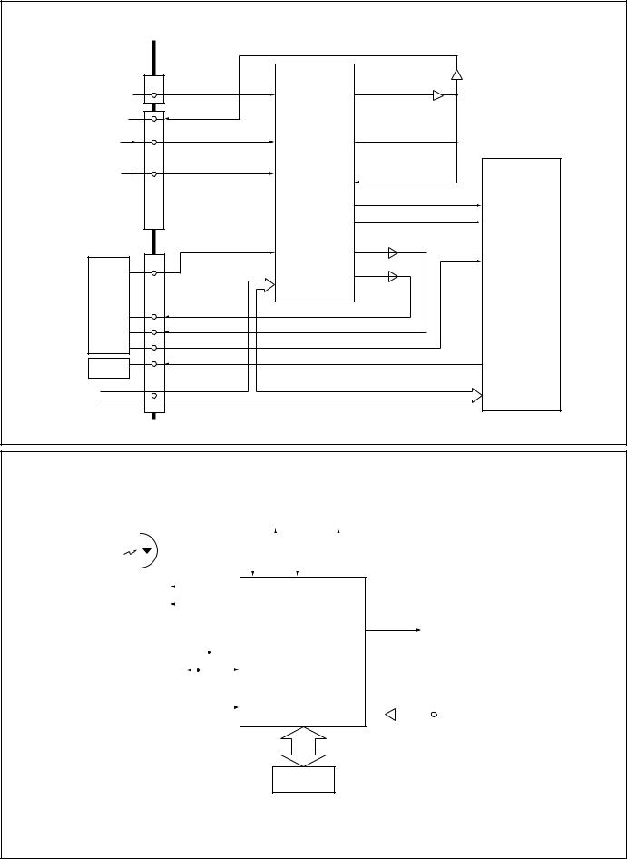
DIAGRAMBLOCK |
|
|
|
Aerial |
|
|
|
|
|
|
|
|
|
Q711 |
|
|
|||||
|
|
|
|
|
|
|
|
|
|
|
Q721 |
|
|
||||||
|
|
|
|
|
|
|
|
|
|
|
|
|
|
|
|||||
|
|
|
|
A101 |
|
|
|
|
|
|
|
VIDEO-OUT |
|
|
|||||
|
|
|
|
|
|
|
|
|
|
|
|
|
|
|
|
||||
|
|
|
|
TUNER |
|
|
|
|
|
20 |
Q242 |
R |
|
R |
|
|
|||
|
|
|
|
|
|
|
|
X132 |
|
|
|
|
G |
|
|
||||
|
|
|
|
|
Q141 |
|
|
21 |
Q243 |
G |
|
|
CRT |
||||||
|
|
|
|
|
|
|
|
VIF |
6 |
Q244 |
B |
|
B |
|
|||||
|
|
|
|
|
|
|
|
|
7 |
22 |
|
|
|
|
|
models |
|
||
|
|
|
|
|
|
|
|
|
|
|
|
|
|
|
|
|
|||
|
|
|
|
|
|
|
|
|
|
IC201 |
|
|
|
|
|
|
|
|
|
|
|
|
|
|
|
|
|
X131 |
|
|
|
|
|
|
|
|
|
|
|
|
|
PC-IN |
POWER |
|
|
|
SIF |
9 |
|
|
|
|
|
|
TV-OUT |
|
|
||
|
|
|
|
|
|
|
|
|
|
|
|
and |
|
||||||
|
|
|
|
|
|
54 |
|
|
|
|
|
|
|
||||||
|
|
|
|
|
|
|
|
|
|
|
AV1 |
|
|
||||||
|
|
|
|
|
|
|
|
|
|
IF/VIDEO/ |
Q121~Q133 |
|
|
|
|
||||
|
|
|
|
|
|
|
|
|
|
CHROMA/ |
|
|
|
TV-IN |
|
|
|
|
|
|
|
|
25 |
26 |
|
|
|
|
|
|
|
|
13 |
SC-1 |
|
therefore |
|
||
|
|
|
|
|
|
|
|
|
|
DEF |
|
|
|
|
|
|
|||
|
|
|
|
|
|
|
|
|
34 |
|
|
|
SIF-IN |
|
|
|
|||
|
|
|
|
|
|
|
2 |
|
|
|
|
|
|
|
|
||||
|
|
|
|
|
|
|
|
|
|
|
|
8 |
|
|
|
||||
|
|
|
|
|
|
|
I C BUS |
35 |
3 |
|
|
|
|
|
|
|
|||
|
|
|
|
|
|
|
|
|
|
|
|
|
|
|
|
||||
|
|
|
|
|
44 |
BLK |
|
BLK |
15 |
43 |
C |
|
|
C-OUT |
15 |
SC-2 |
|
|
|
|
|
|
|
|
|
R |
|
|
|
Y-OUT |
AV2 |
|
|
||||||
|
|
|
|
|
45 |
B |
|
16 |
39 |
Y |
|
|
18 |
|
|
||||
-3- |
|
|
|
IC801 |
46 |
G |
|
G |
17 |
40 |
|
|
|
|
|
MONTO |
|
differs |
|
|
|
|
R |
|
B |
SYNC-IN |
|
|
|
|
|
|
|||||||
|
SCL |
|
47 |
|
18 |
41 |
|
|
|
|
-OUT |
|
|
||||||
|
|
|
|
|
|
EW-OUT |
|
|
Refer also |
|
|
|
|||||||
IC803 |
24 |
CPU |
|
|
|
|
|
32 |
|
|
|
|
|
|
|||||
|
|
|
|
|
26 |
|
|
|
to FIG.-2. |
|
|
|
|
||||||
SDA |
|
|
|
|
|
|
|
|
|
|
|
|
|||||||
MEMORY |
23 |
|
|
|
|
|
|
|
|
|
|
|
|
|
|||||
|
|
|
|
|
|
|
|
|
AV SELECTOR |
|
|
|
|||||||
|
|
|
|
|
|
|
|
|
|
|
H-OUT |
|
T451 |
|
slightly |
|
|||
|
|
|
|
|
|
|
|
|
|
|
|
NICAM DECODER |
|
|
|||||
|
|
|
|
|
|
|
|
|
|
|
|
|
|
|
|
||||
|
|
|
|
|
60 |
CVBS-IN |
|
|
|
|
|
|
|
|
|
FBT |
|
|
|
|
|
|
|
|
61 |
|
|
|
|
|
|
|
|
|
|
|
|
|
|
|
|
|
|
|
|
|
|
|
|
|
|
|
T431 |
Q432 |
|
|
|
|
|
|
|
|
|
|
|
|
|
|
|
|
|
|
|
|
|
FOCUS |
|
||
|
PROTECT-IN |
19 |
1 - 15 |
|
|
|
|
|
|
|
|
|
|
|
|
the from |
|
||
|
|
|
|
|
|
|
|
|
|
|
|
|
SCREEN |
|
|||||
|
|
|
|
|
|
|
|
|
|
|
|
|
|
|
|
||||
|
|
|
|
80 - 63 |
|
|
|
|
|
|
Q431 |
|
|
|
|
|
|
||
|
|
|
|
|
|
|
|
|
|
|
|
|
|
|
|
|
|||
|
|
|
|
IC802 |
|
|
|
|
|
|
|
|
|
|
|
|
|
|
|
|
|
|
|
|
|
|
|
|
|
|
|
|
|
|
|
|
actual |
|
|
|
|
|
|
ROM |
|
|
|
|
|
|
|
|
|
PCC |
|
|
|
|
|
|
|
|
|
|
|
|
|
|
|
|
|
|
|
|
|
|
|
||
|
|
|
|
|
|
|
|
|
|
|
|
|
CONTROL |
|
D.Y |
|
|
||
|
|
|
|
|
|
|
|
|
|
|
|
|
|
|
|
|
|
|
|
|
|
|
|
|
|
|
|
|
|
V-OUT IC501 |
|
|
CS |
|
V |
|
block |
|
|
|
|
|
|
|
|
|
|
|
|
|
CONTROL |
|
|
|
|
||||
|
|
|
|
|
|
|
|
|
|
|
3 |
|
|
|
|
|
|
|
|
|
|
|
|
|
|
|
|
|
|
6 |
|
|
|
|
H |
|
.diagram |
|
|
|
|
|
|
|
|
|
|
|
|
|
|
|
|
|
|
|
|
||
|
|
|
|
|
|
|
|
|
|
|
|
|
|
|
|
|
|
|
|
C3SEV |
|
|
|
|
|
|
|
|
|
|
|
|
|
|
|
|
|
|
|
AV Selector |
|
|
IC1201 |
|
|
|
|
|
NICAM DECODER |
|
|
|
|
|
|
||
|
|
AV-SELECTOR |
|
|
|
|||
|
|
|
|
|
|
|||
|
|
|
<MM1313> |
|
|
|
|
|
|
K12H |
|
|
|
|
Q1203 |
|
|
|
|
|
|
|
|
|
||
FRONT-AV |
FRONT AV3 |
|
1(V) |
(V)34 |
MONITOR-OUT |
|
|
|
|
|
|
|
|
|
|||
|
MONITOR-OUT |
|
2(L) |
|
|
Q1202 |
|
|
|
|
4(R) |
|
|
|
|
|
|
|
|
|
|
|
|
|
|
|
SC-1 |
SC-1 |
|
13(V) |
31 |
|
Y-IN |
|
|
(VIDEO/AUDIO-L/R) |
|
|
|
|
|
|||
|
|
14(L) |
|
|
|
|
|
|
|
|
|
|
|
|
|
|
|
SC-2 |
SC-2 |
|
16(R) |
|
|
|
|
IC3451 |
|
7(V) |
|
|
C-IN |
|
|||
(VIDEO/Y/C/AUDIO-L/R) |
29 |
|
|
|||||
|
8(L) |
|
|
|
NICAM |
|||
|
|
|
|
|
|
|
||
|
|
|
9(Y) |
|
|
L-OUT |
|
|
|
|
|
10(R) |
33 |
|
37 |
& |
|
|
|
|
|
|
||||
|
K12J |
|
11(C) |
32 |
R-OUT |
36 STEREO |
||
|
|
|
|
|
||||
|
|
|
|
|
Y-OUT |
Q1204/1207 |
<TDA9875> |
|
|
|
|
41(V) |
37 |
|
|
||
|
(VIDEO) |
|
|
|
12 |
|
||
|
|
|
|
C-OUT |
|
|
||
|
|
|
|
38 |
Q1205 |
|
|
|
IC201 |
|
|
|
|
|
|
|
|
|
|
|
|
|
|
|
|
|
IF/VIDEO/ |
|
|
|
|
|
|
|
|
CHROMA |
C-OUT |
|
|
|
|
|
|
|
|
|
|
|
|
|
|
|
|
|
Y-OUT |
|
|
|
|
|
|
|
|
SIF-IN |
|
|
|
|
|
|
|
IC001 |
AUDIO L/R-OUT |
|
|
|
|
AUDIO-OUT |
60 |
|
|
|
|
|
|
|
61 |
|
|
AUDIO-OUT |
|
|
|
|
|
|
|
|
|
|
|
|
|
|
|
|
|
I2C BUS |
|
SDA/SCL |
|
|
|
4 |
|
|
|
|
|
|
|
|
|
||
|
|
|
|
|
|
|
5 |
|
Fig.-2
System Control
|
|
|
|
|
|
RC-IN |
||||||||
|
|
|
|
|
|
|||||||||
|
|
|
|
|
|
|
|
|
|
|
|
|
|
|
|
|
|
|
|
|
|
|
|
|
|
|
|
|
|
I2C BUS |
|
|
|
|
|
|
|
|
25 |
|||||
|
|
|
|
|
|
|
|
|||||||
|
|
|
|
|
|
|
|
|||||||
CONTROL |
|
|
|
|
SCL |
|
|
|
||||||
|
|
|
|
|
|
|
||||||||
|
|
|
|
|
|
|
|
|
|
|
|
|||
|
|
IC803 |
|
|
|
|
24 |
|
||||||
|
|
|
|
|
|
|
|
|
||||||
|
MEMORY |
|
|
|
SDA |
|
|
|
23 |
|
||||
|
|
|
|
|
|
|
||||||||
|
|
|
|
|
|
|
|
|
|
|
|
|
19 |
|
|
|
|
|
|
|
|
|
|
|
|
|
|
|
|
|
|
|
POWER-FAIL |
|
|
|||||||||
|
|
|
|
|
|
|||||||||
|
|
|
|
|
DETECT |
|
|
|
||||||
|
||||||||||||||
POWER |
|
KEY-IN |
|
MUTE |
|
|
|
||||
|
|
|
|
|
|
26 |
28 |
40 |
|||
44  BLK-OUT
45  B-OUT
B-OUT
46 G-OUT
IC801 47  R-OUT CPU
|
60 |
|
CVBS |
|
1 - 7, 63 - 80 |
Q806 |
|||
61 |
|
|||
|
|
IC802
ROM
Fig.-3
-4-
C3SEV
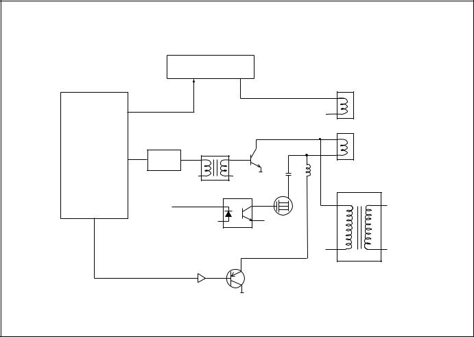
Deflection Control
|
|
|
IC501 |
|
|
V-Output<LA7846> |
|
|
|
6 |
3 |
IC201 |
26 |
V-Drive |
|
|
|
||
IF/VIDEO/ |
|
|
Q431 |
DEFLECTION |
|
H-Output |
|
<TB1251> |
|
Q431 |
T431 |
|
Drive Trans |
||
|
|
|
|
32 H-Drive
D441
CS SW
41
Screen Width Control
EW-Out
Q461 Pcc Control
Q462
Deflection
Yoke
|
Vert. |
|
|
Coil |
|
|
Horiz. |
|
|
Coil |
|
L461/L462 |
T451 |
|
FlyBack Trans |
||
|
-5-
C3SEV
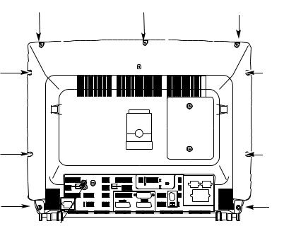
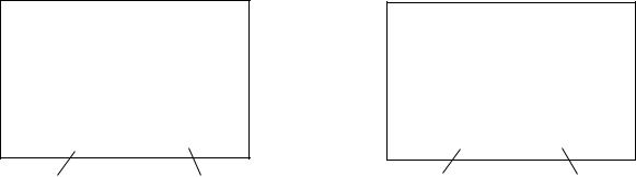
CABINET DISASSEMBLY
CABINET BACK DISASSEMBLY
|
|
|
(A) |
(A) |
|
(A) |
|
|
|
||
|
|
|
|
1. Remove 10 screws(A).
2. Pull out the cabinet back.
(A) |
(A) |
(A) |
(A) |
(A) |
(A) |
(A)
-6-
C3VES

OPTION SETTING
[After replacing the Memory IC (IC803)]
The memory IC, IC803, stores the option data of TV set and service adjustments data for each circuit, therefore, when the memory IC is replaced, it should be performed following setting and “SERVICE ADJUSTMENT” on next page.
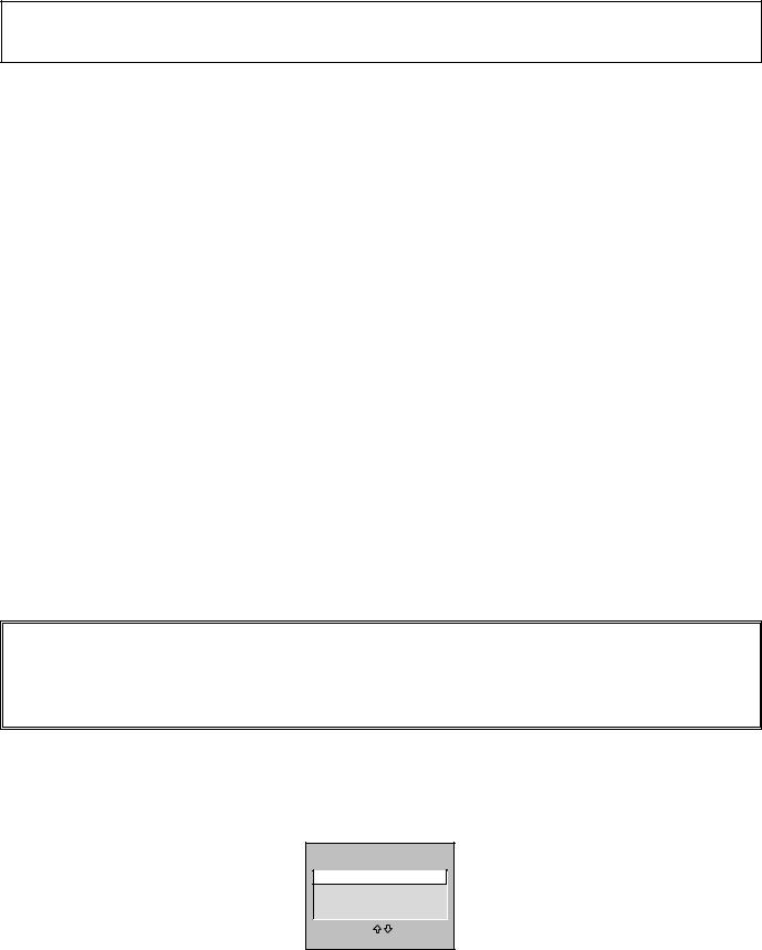
To enter to the Option Mode
+Press and hold the F/OK button on the remote control and P▼ button on the front panel of the TV. The option window will appear on the screen. Set the options as shown below.
OPTION
ON-TIMER |
ON |
|
SORT MODE |
AUTO TUNE/SORT |
|
PLUG & PLAY |
ON |
|
WELCOME TEXT |
ON |
|
CODE TEST |
OFF |
|
WSS |
ON |
|
WIDE |
OFF |
|
OPTION |
UK |
|
312/313 Mode |
OFF |
|
AV3 OPTION |
ON |
|
3D SURROUND |
ON |
|
ADJUST : |
EXIT : RECALL |
To set the option mode
+Highlight the desired option item by using the P▲ or P▼ button .
+To switch the option mode, use the Volume - (LEFT) or Volume + (RIGHT) button.
+The data which is set in the option mode is stored into the memory IC automatically.
Following table shows the available option items and default setting mode.
Option Mode |
Mode |
Description & Note |
ON-TIMER |
ON or OFF |
On-timer available, default “ON” |
SORT MODE |
AUTO TUNE/SORT |
Tuning mode, default “AUTO TUNE/SORT” |
|
or AUTO TUNE |
|
|
or ATS EURO PLUS |
|
PLUG & PLAY |
ON or OFF |
Plug & Play mode, default “ON” |
WELCOME TEXT |
ON or OFF |
Display message when first set up, default “ON” |
CODE TEST |
OFF or ON |
For factory use, default “OFF” |
WSS |
ON or OFF |
Wide Screen Signaling available, default “ON” |
WIDE |
ON or OFF |
Wide mode, default “ON” |
OPTION |
UK or IRELAND |
Destination option , default “UK” |
312/313 Mode |
ON or OFF |
Teletext mode, default OFF |
AV3 OPTION |
ON or OFF |
Front AV disable, default ON |
3D SURROUND |
ON or OFF |
3D Surround available, default ON |
|
|
|
Exit from the Service Mode
+ Press the RECALL button.
-7-
C3SEV
SERVICE ADJUSTMENTS
Note: Some items of the service adjustments for this chassis are controlled by the CPU, IC801, and the adjustments are carried out by using the RC handset.
[After replacing the Memory IC (IC803)]
The memory IC, IC803, stores the service adjustments data for each circuit, therefore, when the memory IC is replaced, it should be performed “OPTION SETTING” on previous page and the following adjustments, refer to further adjustment on page 14.
ADJUSTABLE SERVICE ADJUSTMENT
REGULAR
|
Item No. |
OSD |
Description |
|
1 |
AGC |
AGC Adjustment |
|
2 |
CUT |
Cut-Off Drive Adjustment |
|
3 |
GRY |
G-Drive Adjustment |
|
4 |
GRY |
B-Drive Adjustment |
|
7 |
HBP |
H-Blanking Phase Adjustment |
|
8 |
OSD |
OSD Positioning Adjustment |
|
|
|
|
WIDE |
|
|
|
|
|
|
|
|
Item No. |
OSD |
Description |
|
1 |
P V-P |
Vertical Centre Adjustment |
|
2 |
P H-P |
Horizontal Centre Adjustment |
|
5 |
P V-S |
Vertical Size Adjustment |
|
6 |
P H-S |
Horizontal Size Adjustment |
|
7 |
P PCC |
Pcc Adjustment |
|
8 |
P TRP |
Trapezoid Distortion Adjustment |
|
10 |
P CNR |
Corner Adjustment |
|
|
|
|
IMPORTANT NOTICE
Do not attempt to adjust service adjustments not listed on the above otherwise it may cause loss of performance and product safety.
To enter to the Service Mode
+Press and hold the GREEN button on the remote control and then press the P▼ button inside of the door. The adjustment window will appear on the screen.
ADJUST |
|
REGULAR |
|
WIDE |
|
OTHERS |
|
TB1251 |
|
SELECT: |
OK |
EXIT : RECALL |
|
-8-
C3SEV
To select the mode and service item and change data value
+Highlight the desired adjustment mode by using the P▲ or P▼ button and then press the F/OK button.
+To select the adjustment item, use the P▲ or P▼ button.
+To change the service data, use the Volume -(LEFT) or Volume + (RIGHT) button.
+The data which is set in the service mode is stored into the memory IC automatically.
REGULAR mode |
WIDE mode |
REGULAR |
|
1, AGC |
38 |
WIDE |
|
1. P V-P |
1F |
Adjustment No. |
Adjustment Data |
Adjustment No. |
Adjustment Data |
and Item name |
|
and Item name |
|
Exit from the Service Mode
+ Press the RECALL button or turn off the TV set by using the Mains switch.
INITIALISATION OF MEMORY IC
To initialise the memory IC (IC803), press and hold the NORMAL button on te remote control and then press the P▲ button on the front panel of the TV set, and then turn the Mains switch Off and On. Now the initialisation is completed.
When initialised the memory IC, all of the setting data (option data and service adjustment data) stored in the IC are reset to the default value. So it is necessary to set the option settings and readjust the service adjustments listed on left page.
-9-
C3SEV
ADJUSTMENTS
IMPORTANT NOTICE
Do not attempt to adjust the following service adjustments except when adjustments are required in servicing otherwise it may cause loss of performance and product safety.
+B VOLTAGE ADJUSTMENT
1.Receive white raster pattern.
2.Set controls to normal.
3.Connect digital voltmetre to test point TP-B and GND.
4.Adjust voltage to 150 ±0.5V by using VR641.
AGC ADJUSTMENT
1.Input and tune an RF signal which is UHF to the clearest station.
2.Connect digital voltmetre to test point TP-A and GND.
4.Enter to the service mode and select mode “REGULAR”, and select item no.1 “REGULAR 1, AGC”.
5.Press the LEVEL+ or LEVEL - button to adjust voltage to be 3.2Vdc.
FOCUS ADJUSTMENT
By using FOCUS VR, adjust focus control for well defined scanning lines.
GREY SCALE ADJUSTMENT
SCREEN ADJUSTMENT
1.Receive black & white pattern.
2.Enter to the service mode and select mode “REGULAR”, and select item no. 2 “REGULAR 2, CUT”. The horizontal line will appear on the screen.
3.Set the SCREEN VR for one colour to be just visible.
4.Using the numeric buttons shown set each colour to minimum by decreasing to the point where any further
decrease resets the adjustment to maximum value.
BIAS ADJUSTMENT
5.By using the buttons 1, 2, 4, 5, 7, 8 on the remote control, adjust the line to be white.
The key allocation is as follows;
Button No. Operation
1Increase Red
2Decrease Red
4Increase Green
5Decrease Green
7Increase Blue
8Decrease Blue
DRIVE ADJUSTMENT
6.Select item no.3 “REGULAR 3, GRY” (G-Drive) or 4 “REGULAR 4, GRY” (B-Drive) and adjust both initially to 3F.
7.Change data value of each item by using LEVEL + or LEVEL - button to obtain the proper white balance.
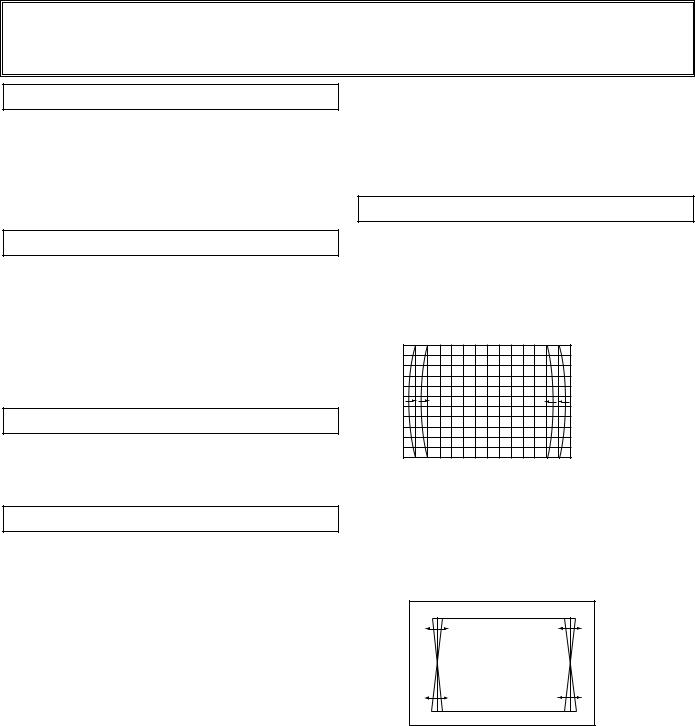
PCC ADJUSTMENT
PCC ADJUSTMENT
1.Receive cross hatch pattern and set screen mode to “FULL”.
2.Enter to the service mode and select mode “WIDE”, and select item no. 7 “WIDE 7.P PCC”.
3.Press the LEVEL+ or LEVEL - button to adjust the vertical line to be straight.
TRAPEZOID ADJUSTMENT
1.Receive cross hatch pattern and set screen mode to “FULL”.
2.Enter to the service mode and select mode “WIDE”, and select item no. 8 “WIDE 8.P TRP”.
3.Press the LEVEL+ or LEVEL - button to correct the trapezum distortion of the vertical line.
-10-
C3SEV
 Loading...