


Sanyo CE25D5-C Schematic
Part No. SKSM0381 C2VTV/VTS AUGUST 2000
Colour Tele vision
Ser vice Manual
Model CE25D5-C
Service Ref. No. CE25D5-C-00
CE25D5-C-01
CE25D5-C-02
PRODUCT CODE: 111351215
ORIGINAL VERSION: Chassis No. EB6-A
Give complete "SERVICE REF. NO." for parts
order or servicing, it is shown on the rating sheet
on the cabinet back of the TV set.
Note
This TV receiver will not work properly in foreign
countries where the television transmission
system and power source differ from the design
specifications. Refe r t o the specifications for the
design specifications
CE25D5-C
Contents
Safety precautions/Specifications . . . . . . . . . . . . . . . . . . . . . . . . . . . . . . . . . . . . . . . . . . . . . 2
Block diagrams . . . . . . . . . . . . . . . . . . . . . . . . . . . . . . . . . . . . . . . . . . . . . . . . . . . . . . . . . . . 3~5
Cabinet Disassembly . . . . . . . . . . . . . . . . . . . . . . . . . . . . . . . . . . . . . . . . . . . . . . . . . . . . . . 6
Adjustment and Repair Procedures. . . . . . . . . . . . . . . . . . . . . . . . . . . . . . . . . . . . . . . . . . . . 7~11
CPU Functions . . . . . . . . . . . . . . . . . . . . . . . . . . . . . . . . . . . . . . . . . . . . . . . . . . . . . . . . . . . . 12~13
Component Locations. . . . . . . . . . . . . . . . . . . . . . . . . . . . . . . . . . . . . . . . . . . . . . . . . . . . . . 14~15
IC Block Diagrams . . . . . . . . . . . . . . . . . . . . . . . . . . . . . . . . . . . . . . . . . . . . . . . . . . . . . . . . 16~20
Pin description of semiconductors . . . . . . . . . . . . . . . . . . . . . . . . . . . . . . . . . . . . . . . . . . . . . 21
Part Description and reading of schematic diagram . . . . . . . . . . . . . . . . . . . . . . . . . . . . . . . . 22
Cabinet Parts List. . . . . . . . . . . . . . . . . . . . . . . . . . . . . . . . . . . . . . . . . . . . . . . . . . . . . . . . . 23
Electric Parts List . . . . . . . . . . . . . . . . . . . . . . . . . . . . . . . . . . . . . . . . . . . . . . . . . . . . . . . . 24~31
-2-
C2VTV
SAFETY PRECAUTION
X-RADIATION PRECAUTION
The primary source of X-RADIATION in the television receiver is the picture tube.The picture tube is specially
constructed to limit X-RADIATION emissions. For continued X-RADIATION protection, the replacement tube must
be the same type as the original including suffix letter.Excessive high voltage may produce potentially
hazardous X-RADIATION. To avoid such hazards, the high voltage must be maintained within specified limit.
Refer to this service manual, high voltage adjustment for specific high voltage limit. If high voltage exceeds specified limits, take necessary corrective action. Carefully follow the instructions for +B1 volt power supply adjustment, and high voltage adjustment to maintain the high voltage within the specified limits.
PRODUCT SAFETY NOTICE
SPECIFICATIONS
Product safety should be considered when a component replacement is made in any area of a receiver.
Components indicated by mark in the parts list and the schematic diagram designate components in which
safety can be of special significance.It is particularly recommended that only parts designated on the par ts list in
this manual be used for component replacement designated by mark . No deviations from resistance wattage
or voltage ratings may be made for replacement items designated by mark .
1: An isolation transformer should be connected in the
power line between the receiver and the AC line
when a service is performed on the primar y of the
converter transformer of the set.
2: Comply with all caution and safety-related notes
provided on the cabinet back, inside the cabinet, on
the chassis or the picture tube.
3: When replacing a chassis in the cabinet, always be
certain that all the protective devices are installed
properly, such as, control knobs, adjustment covers or
shields, barriers, isolation resistor-capacitor networks etc.
Before returning any television to the customer, the
service technician must be sure that it is completely
safe to operate without danger of electrical shock.
Power source AC 220~240V, 50Hz
Television system System B/G
Colour system PAL/NTSC4.43 (PAL/NTSC4.43/MTSC3.58 IN AV MODE)
Receiving channel UHF: #21~69
VHF: E2-E12
CATV: X, Y, Z, S1-S41
Aerial input impedance 75ohm
AV terminal
21 Pin SCART Ter minal AV1:CENELEC standard with RGB
AV2:CENELEC standard with S-inputs
Front AV AV3:RCATerminal, Video and Audio (L/R)
Sound output(Music) 12W x 2
Dimensions (WxHxD) 680 x 543 x 442mm
Weight 26 Kg
!
!
!
-3-
C2VTV
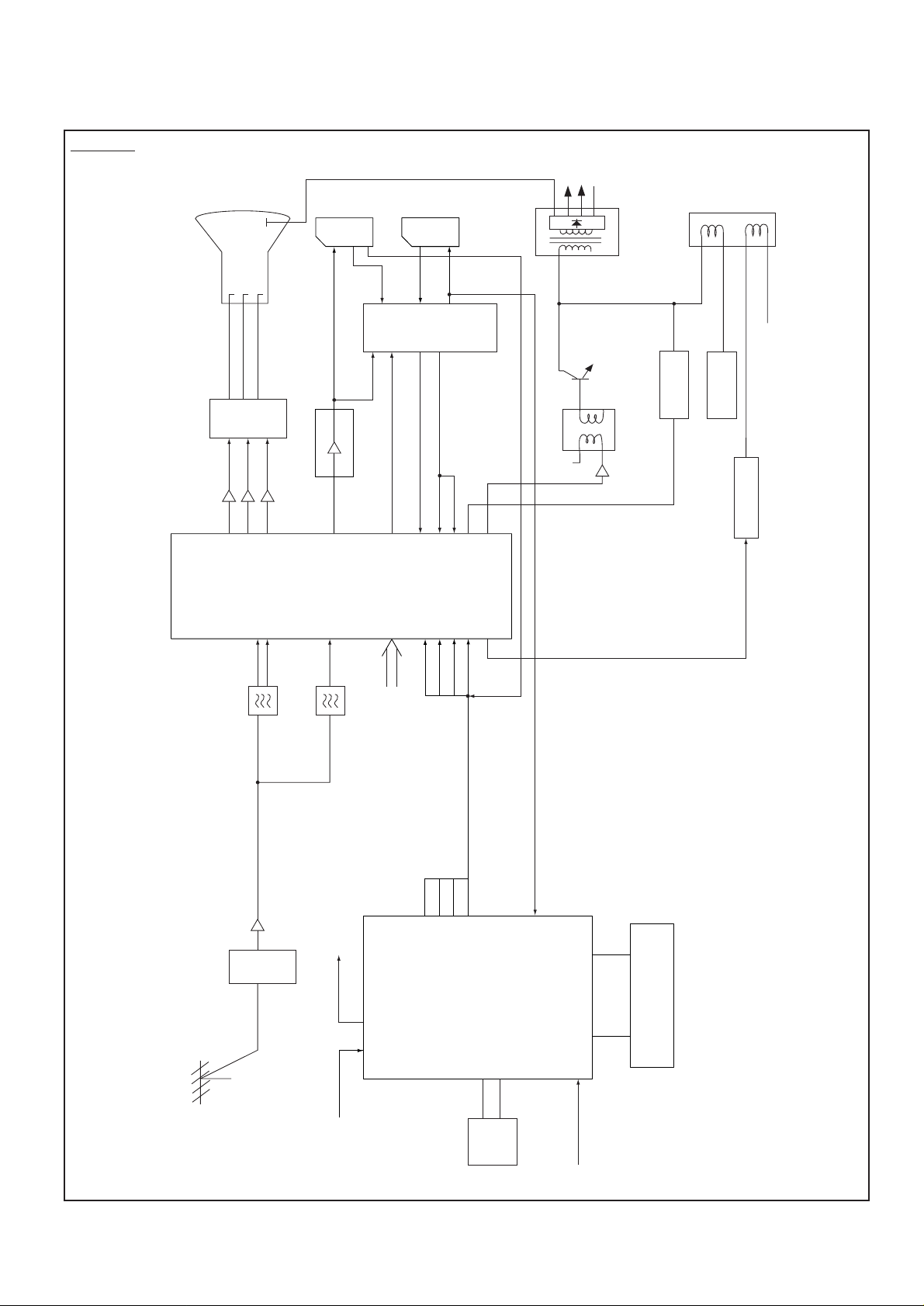
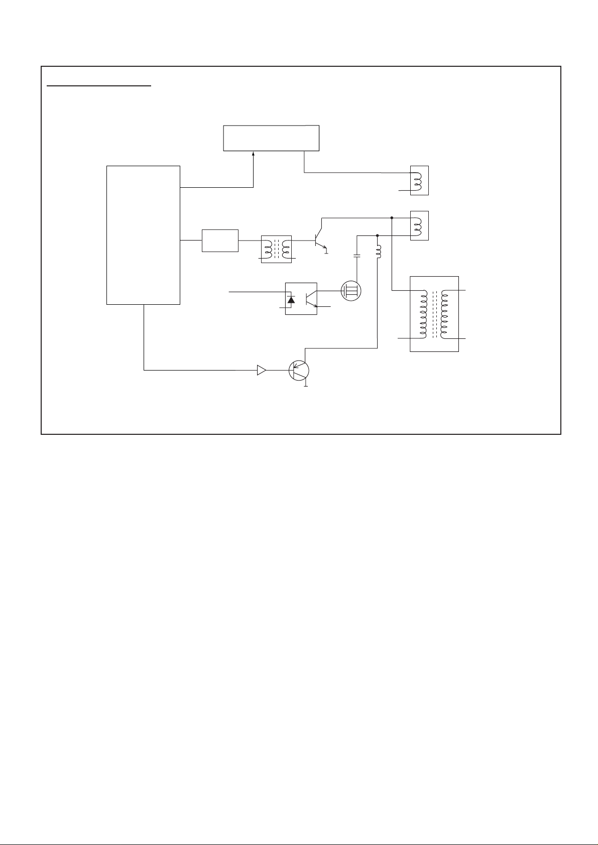
BLOCK DIAGRAM
This is a diagram for all models and therefore differs slightly from the actual block diagram.
Outline
FOCUS
SCREEN
V
AV1
AV2
FBT
T451
D.Y
H
Q701
Q711
R
Q721
R
VIDEO-OUT
Q242
20
CRT
B
G
G
Q243
21
VIF
X132
B
Q244
6
18
Y-OUT
MONTO
-OUT
Refer also
to FIG.-2.
AV SELECTOR
NICAM DECODER
Q432
PCC
CONTROL
CS
CONTROL
TV-OUT
TV-IN
SC-1
13
8
SIF-IN
SC-2
15
C-OUT
T431
Q121~Q133
Y
C
SYNC-IN
22
54
IC201
7
9
SIF
3
DEF
IF/VIDEO/
CHROMA/
34
35
43
394041
1516171826
R
G
BLK
H-OUT
EW-OUT
32
B
Q431
3
6
V-OUT IC501
X131
C BUS
2
I
Aerial
A101
TUNER
Q141
POWER
PC-IN
CPU
24
23
SDA
IC803
MEMORY
CVBS-IN
61
60
PROTECT-IN
1 - 15
19
80 - 63
ROM
IC802
B
R
G
BLK
26
25
44
45
46
47
IC801
SCL
-4-
C2VTV
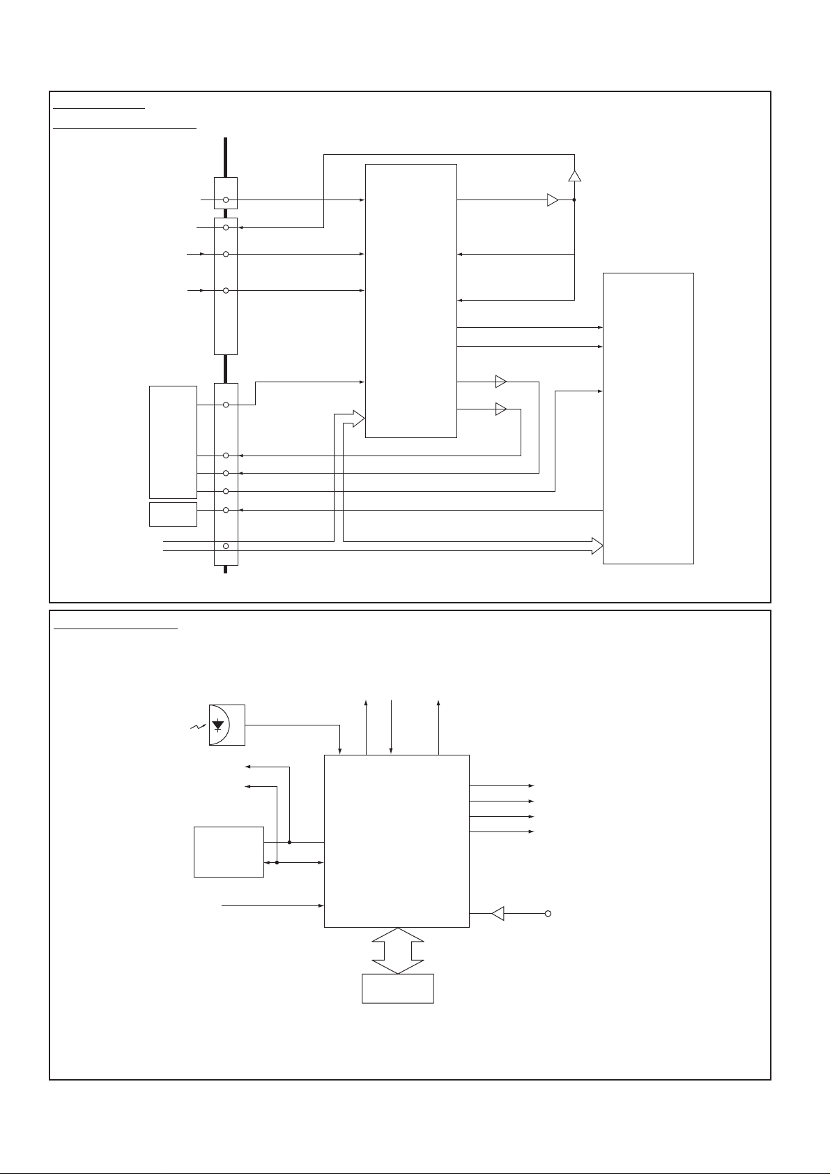
AV Selector
NICAM DECODER
System Control
Fig.-2
Fig.-3
FRONT-AV
SC-1
SC-2
IC201
IF/VIDEO/
CHROMA
IC001
AUDIO-OUT
I2C BUS
K12H
FRONT AV3
MONITOR-OUT
SC-1
(VIDEO/AUDIO-L/R)
SC-2
(VIDEO/Y/C/AUDIO-L/R)
K12J
(VIDEO)
C-OUT
Y-OUT
SIF-IN
AUDIO L/R-OUT
IC1201
AV-SELECTOR
<MM1313>
1(V)
2(L)
4(R)
13(V)
14(L)
16(R)
7(V)
8(L)
9(Y)
10(R)
11(C)
41(V)
SDA/SCL
(V)34
MONITOR-OUT
31
29
33
32
Y-OUT
37
C-OUT
38
Y-IN
C-IN
L-OUT
R-OUT
Q1204/1207
Q1205
Q1202
AUDIO-OUT
Q1203
IC3451
NICAM
37
36
STEREO
<TDA9875>
12
60
61
4
5
&
I2C BUS
CONTROL
IC803
MEMORY
RC-IN
SDA
POWER-FAIL
DETECT
SCL
POWER
25 26 28
IC801
24
23
19
1 - 7, 63 - 80
KEY-IN
CPU
MUTE
40
44
45
46
47
60
61
Q806
BLK-OUT
B-OUT
G-OUT
R-OUT
CVBS
IC802
ROM
-5-
C2VTV
Deflection Control
IC501
V-Output<LA7846>
IC201
IF/VIDEO/
DEFLECTION
<TB1251>
41
EW-Out
63
Deflection
Yoke
26
32
V-Drive
Q431
H-Drive
Q431
H-Output
T431
Drive T r ans
Vert.
Coil
Horiz.
Coil
T451
FlyBack Trans
L461/L462
CS SW
D441
Screen Width Control
Q462
Q461
Pcc Control
-6-
C2VTV
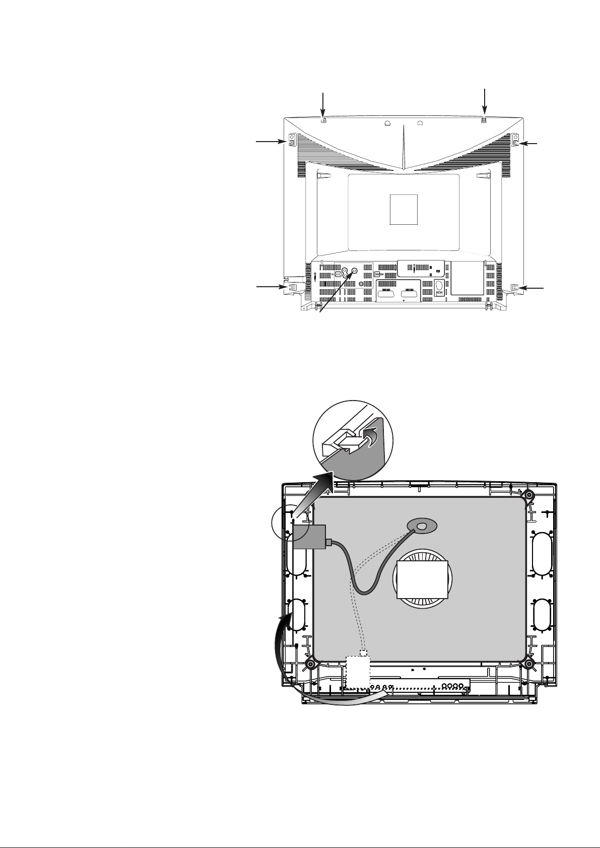
CABINET DISASSEMBLY
CABINET BACK DISASSEMBLY
1. Remove 7 screws(A).
2. Pull out the cabinet back.
PLACING THE CHASSIS T O SERVICE
POSITION
1. Pullout the chassis and put it to the rails on the
side cabinet.
2. Fix main board with hook on the top rail.
(A)
(A)
(A)
(A)
(A)
(A)
(A)
-7-
C2VTV
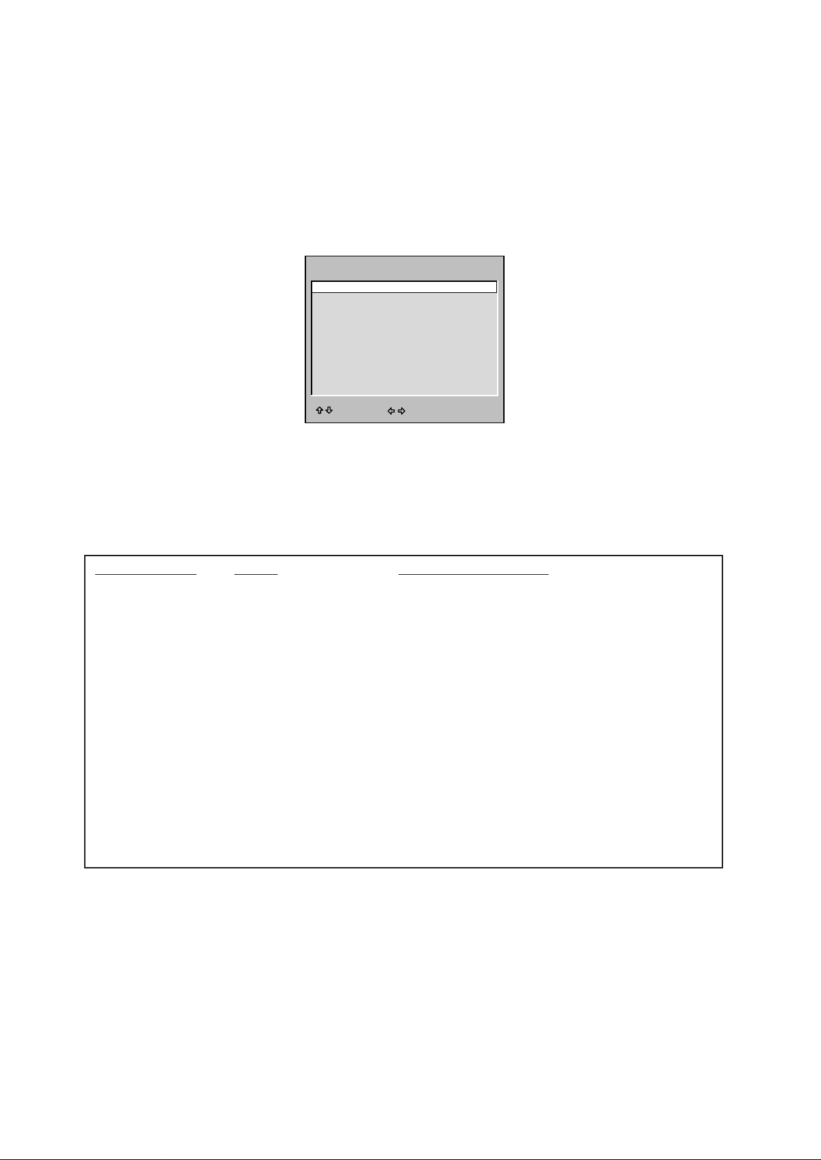
OPTION SETTING
[After replacing the Memory IC (IC803)]
The memory IC, IC803, stores the option data of TV set and service adjustments data for each circuit, therefore,
when the memory IC is replaced, it should be performed following setting and “SERVICE ADJUSTMENT” on next
page.
To enter to the Option Mode
+ Press and hold the F/OK button on the remote control and P▼ button on the front panel of the TV.The option win-
dow will appear on the screen. Set the options as shown below.
To set the option mode
+ Highlight the desired option item by using the P▲ or P▼ button .
+ To switch the option mode, use the Volume - (LEFT) or Volume + (RIGHT) button.
+ The data which is set in the option mode is stored into the memory IC automatically.
Following table shows the available option items and default setting mode.
Exit from the Service Mode
+ Press the RECALL button.
Option Mode Mode Description & Note
ON-TIMER ON or OFF On-timer available, default “ON”
SORT MODE AUTO TUNE/SORT Tuning mode, default “AUTO TUNE/SORT”
or AUTO TUNE
or ATS EURO PLUS
PLUG & PLAY ON or OFF Plug & Play mode, default “ON”
WELCOME TEXT ON or OFF Display message when first set up, default “ON”
CODE TEST OFF or ON For factory use, default “OFF”
WSS ON or OFF Wide Screen Signaling available, default “ON”
WIDE ON or OFF Wide mode, default “ON”
OPTION UK or IRELAND Destination option , default “UK”
312/313 Mode ON or OFF Teletext mode, default OFF
AV3 OPTION ON or OFF Front AV disable, default ON
3D SURROUND ON or OFF 3D Surround available, default ON
OPTION
ON-TIMER ON
SORT MODE AUTO TUNE/SORT
PLUG & PLAY ON
WELCOME TEXT ON
CODE TEST OFF
WSS ON
WIDE OFF
OPTION UK
312/313 Mode OFF
AV3 OPTION ON
3D SURROUND ON
ADJUST : EXIT : RECALL
-8-
C2VTV
SERVICE ADJUSTMENTS
[After replacing the Memory IC (IC803)]
The memory IC, IC803, stores the service adjustments data for each circuit, therefore, when the memory IC is
replaced, it should be performed “OPTION SETTING” on previous page and the following adjustments, refer to
further adjustment on page 14.
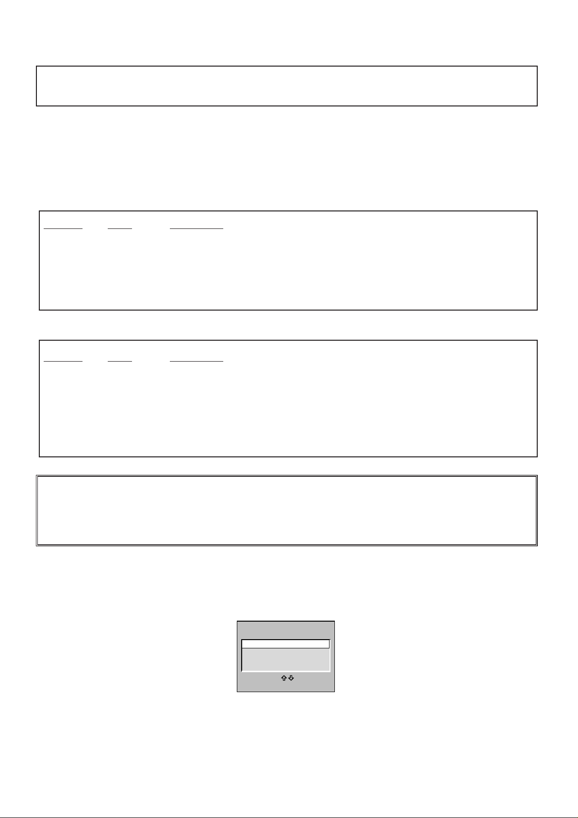
ADJUSTABLE SERVICE ADJUSTMENT
REGULAR
WIDE
To enter to the Service Mode
+ Press and hold the GREEN button on the remote control and then press the P▼ button inside of the door.The
adjustment window will appear on the screen.
IMPORTANT NOTICE
Do not attempt to adjust service adjustments not listed on the above otherwise it may cause
loss of performance and product safety.
Item No. OSD Description
1 P V-P Vertical Centre Adjustment
2 P H-P Horizontal Centre Adjustment
5 P V-S Vertical Size Adjustment
6 P H-S Horizontal Size Adjustment
7 P PCC Pcc Adjustment
8 P TRP Trapezoid Distortion Adjustment
10 P CNR Corner Adjustment
Item No. OSD Description
1 AGC AGC Adjustment
2 CUT Cut-Off Drive Adjustment
3 GRY G-Dr ive Adjustment
4 GRY B-Dr ive Adjustment
7 HBP H-Blanking Phase Adjustment
8 OSD OSD Positioning Adjustment
Note: Some items of the service adjustments for this chassis are controlled by the CPU, IC801, and the
adjustments are carried out by using the RC handset.
ADJUST
REGULAR
WIDE
OTHERS
TB1251
SELECT:
EXIT : RECALL
OK

-9-
C2VTV
To select the mode and service item and change data value
+ Highlight the desired adjustment mode by using the P▲ or P▼ button and then press the F/OK button.
+ To select the adjustment item, use the P▲ or P▼ button.
+ To change the service data, use the Volume -(LEFT) or Volume + (RIGHT) button.
+ The data which is set in the service mode is stored into the memory IC automatically.
Exit from the Service Mode
+ Press the RECALL button or turn off the TV set by using the Mains switch.
INITIALISATION OF MEMORY IC
To initialise the memory IC (IC803), press and hold the NORMAL button on te remote control and then press the P▲
button on the front panel of the TV set, and then turn the Mains switch Off and On. Now the initialisation is
completed.
When initialised the memory IC, all of the setting data (option data and service adjustment data) stored in the IC are
reset to the default value. So it is necessar y to set the option settings and readjust the service adjustments listed on
left page.
REGULAR mode
WIDE mode
REGULAR
1, AGC 38
Adjustment No.
and Item name
Adjustment Data
Adjustment No.
and Item name
WIDE
1. P V-P 1F
Adjustment Data
-10-
C2VTV
ADJUSTMENTS
IMPORTANT NOTICE
Do not attempt to adjust the following service adjustments except when adjustments are required in servicing
otherwise it may cause loss of performance and product safety.
1. Receive white raster pattern.
2. Set controls to nor mal.
3. Connect digital voltmetre to test point TP-B and GND.
4. Adjust voltage to 150 ±0.5V by using VR641.
1. Input and tune an RF signal which is UHF to the clearest station.
2. Connect digital voltmetre to test point TP-A and GND.
4. Enter to the ser vice mode and select mode “REGU-
LAR”, and select item no.1 “REGULAR 1, AGC”.
5. Press the LEVEL+ or LEVEL - button to adjust voltage
to be 3.2Vdc.
By using FOCUS VR, adjust focus control for well
defined scanning lines.
SCREEN ADJUSTMENT
1. Receive black & white pattern.
2. Enter to the ser vice mode and select mode “REGU-
LAR”, and select item no.2 “REGULAR 2, CUT”.The
horizontal line will appear on the screen.
3. Set the SCREEN VR for one colour to be just visible.
4. Using the numeric buttons shown set each colour to
minimum by decreasing to the point where any further
decrease resets the adjustment to maximum value.
BIAS ADJUSTMENT
5. By using the buttons 1, 2, 4, 5, 7, 8 on the remote
control, adjust the line to be white.
The key allocation is as follows;
Button No. Operation
1 Increase Red
2 Decrease Red
4 Increase Green
5 Decrease Green
7 Increase Blue
8 Decrease Blue
DRIVE ADJUSTMENT
6. Select item no.3 “REGULAR 3, GRY” (G-Drive) or 4
“REGULAR 4, GRY” (B-Drive) and adjust both initially
to 3F.
7. Change data value of each item by using LEVEL + or
LEVEL - button to obtain the proper white balance.
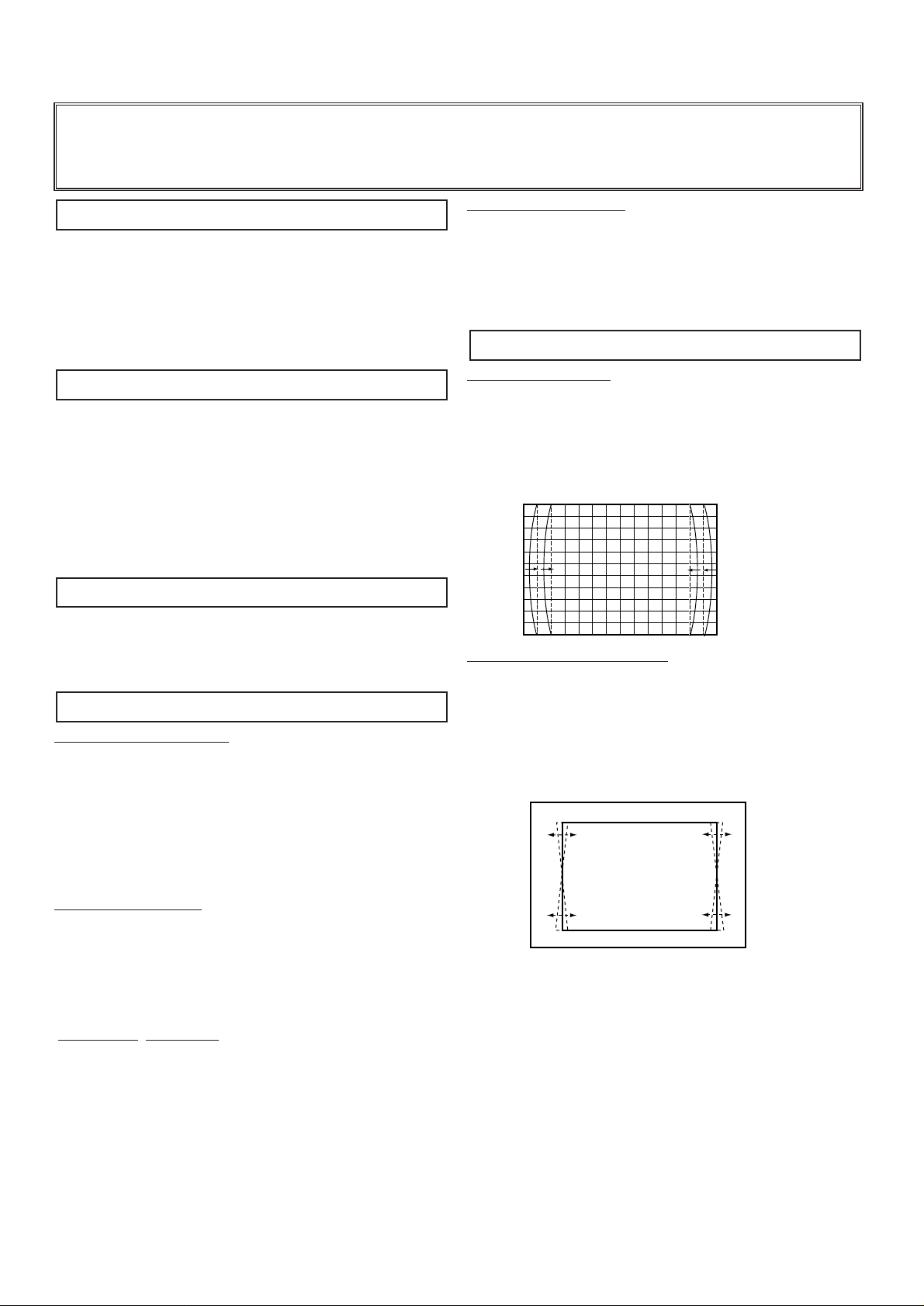
PCC ADJUSTMENT
1. Receive cross hatch pattern and set screen mode to
“FULL”.
2. Enter to the ser vice mode and select mode “WIDE”,
and select item no.7 “WIDE 7.P PCC”.
3. Press the LEVEL+ or LEVEL - button to adjust the
vertical line to be straight.
TRAPEZOID ADJUSTMENT
1. Receive cross hatch pattern and set screen mode to
“FULL”.
2. Enter to the ser vice mode and select mode “WIDE”,
and select item no.8 “WIDE 8.P TRP”.
3. Press the LEVEL+ or LEVEL - button to correct the
trapezum distortion of the vertical line.
PCC ADJUSTMENT
GREY SCALE ADJUSTMENT
FOCUS ADJUSTMENT
AGC ADJUSTMENT
+ B VOLTAGE ADJUSTMENT
 Loading...