


OWNER’S MANUAL
GUIDE D’UTILISATION
29” CLASS LED-LCD HDTV
LED-LCD HDTV GRAND CATÉGORIE 29 PO
SLED2900
SLED2900A
FRANÇAIS ENGLISH

ATTENTION
ATTENTION
If you purchase a universal remote control from your local retailer, please contact the remote manufacturer for the required programming code.
Si vous utilisez avec cet appareil une télécommande universelle (autre que celle vendue avec ce téléviseur), consultez la documentation accompagnant la télécommande universelle afin de connaître le code numérique correspondant au téléviseur.
AIR/CABLE MODE SELECTION
SÉLECTION DU MODE AIR/CABLE
When shipped from the factory, the Signal Type option is set to the “Cable” (Cable Television) mode. If not using Cable TV, set this menu option to the “Air” position.
Lorsque l’appareil sort de l’usine, l’option Signal Type est en mode « Cable » (câblodistribution). Si vous n’utilisez pas la câblodistribution, sélectionnez l’option « Air ».
IF CONTACT WITH CUSTOMER SERVICE IS REQUIRED
PLEASE HAVE THE MODEL NUMBER READY PRIOR TO THE CALL.
SI VOUS DEVEZ COMMUNIQUER AVEC LE SERVICE CLIENTÈLE, PRENEZ NOTE
DU NUMÉRO DE MODÈLE AVANT D’APPELER.
CUSTOMER SERVICE – 1-800-289-0980
SERVICE/SERVICE CLIENTÈLE: 1-800-289-0980
ORION WEBSITE
SITE WEB ORION
FOR INFORMATION ON OUR OTHER PRODUCTS, TO ORDER ACCESSORIES ONLINE,
OR FOR RECYCLING INFORMATION, PLEASE VISIT OUR WEBSITE AT
POUR OBTENIR DES INFORMATIONS SUR NOS AUTRES PRODUITS, POUR COMMANDER DES ACCESSOIRES,
OU LE RECYCLAGE, VEUILLEZ VISITER NOTRE SITE WEB: www.sansuiproducts.com
Before operating the unit, please read this manual thoroughly.
Avant de faire fonctionner l’appareil, veuillez lire le présent guide attentivement.
ENGLISH
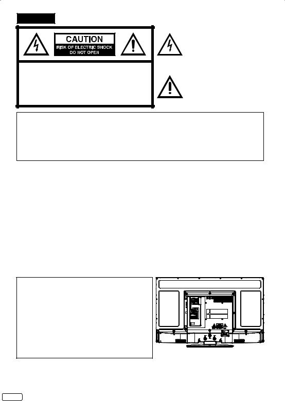
CAUTION:TO REDUCE THE RISK OF ELECTRIC SHOCK, DO NOT REMOVE COVER (OR BACK). NO USER-SERVICEABLE PARTS INSIDE. REFER SERVICING TO QUALIFIED SERVICE PERSONNEL.
The lightning flash with arrowhead symbol, within an equilateral triangle is intended to alert the user to the presence of uninsulated dangerous voltage within the product's enclosure that may be of sufficient magnitude to constitute a risk of electric shock.
The exclamation point within an equilateral triangle is intended to alert the user to the presence of important operating and maintenance (servicing) instructions in the literature accompanying the appliance.
WARNING: TO PREVENT FIRE OR SHOCK HAZARD, DO NOT EXPOSE THIS APPLIANCE TO RAIN OR MOISTURE.
TO PREVENT THE SPREAD OF FIRE, KEEP CANDLES OR OPEN FLAMES AWAY FROM THIS PRODUCT AT TIMES.
CAUTION: TO PREVENT ELECTRIC SHOCK. DO NOT USE THIS POLARIZED PLUG WITH AN EXTENSION CORD, RECEPTACLE OR OTHER OUTLET UNLESS THE BLADES CAN BE FULLY INSERTED TO PREVENT BLADE EXPOSURE.
WARNING: This equipment has been tested and found to comply with the limits for a Class B digital device, pursuant to Part 15 of the FCC Rules. These limits are designed to provide reasonable protection against harmful interference in a residential installation. This equipment generates, uses and can radiate radio frequency energy and, if not installed and used in accordance with the instructions, may cause harmful interference to radio communications.
However, there is no guarantee that interference will not occur in a particular installation. If this equipment does cause harmful interference to radio or television reception, which can be determined by turning the equipment off and on, the user is encouraged to try to correct the interference by one or more of the following measures:
- Reorient or relocate the receiving antenna.
- Increase the separation between the equipment and receiver.
- Connect the equipment into an outlet on a circuit different from that to which the receiver is connected. - Consult the dealer or an experienced radio/TV technician for help.
CAUTION: Changes or modifications not expressly approved by the party responsible for compliance with the FCC Rules could void the user's authority to operate this equipment.
Location of the required marking
The rating sheet and the safety caution are on the rear of the unit.
FCC Declaration of Conformity Compliance Statement (Part 15):
The Sansui SLED2900 and SLED2900A , LED-LCD HDTV complies with Part 15 of the FCC rules.
Operation is subject to the following two conditions: (1) this device may not cause harmful interference, and (2)
this device must accept any interference received, including interference that may cause undesired operation.
The party responsible for compliance to these rules is:
ORION AMERICA,INC.
1105 SOUTH MAIN STREET PRINCETON, INDIANA 47670,U.S.A
Ph: 1-800-289-0980
Record the model number and serial number.
Model number _______________ Serial number _______________
EN 2

IMPORTANT SAFETY INSTRUCTIONS
15)Apparatus should not be exposed to dripping or splashing, and objects filled with liquids, such as vases, should not be placed on the apparatus.
16)An outside antenna system should not be located in the vicinity of overhead power lines or other electric light or power circuits, or where it can fall into such power lines or circuits. When installing an outside antenna system, extreme care should be taken to keep from touching such power lines or circuits, as contact with them might be fatal.
17)Do not overload wall outlets and extension cords, as this can result in a risk of fire or electric shock.
18)Do not push objects through any openings in this unit, as they may touch dangerous voltage points or short out parts that could result in fire or electric shock. Never spill or spray any type of liquid into the unit.
19) If an outside antenna or cable system |
EXAMPLE OF ANTENNA GROUNDING AS PER THE NATIONAL ELECTRICAL CODE |
|||||||
is connected to the unit, be sure the |
|
|
|
|
|
|
|
|
antenna or cable system is grounded |
|
|
|
|
|
|
|
ANTENNA LEAD IN WIRE |
to provide some protection against |
GROUND |
|
|
|
|
|
||
voltage surges and built-up static |
|
|
|
|
ANTENNA |
|||
CLAMP |
|
|
|
|
||||
charges, Section 810 of the National |
|
|
|
|
|
|
|
DISCHARGE UNIT |
Electrical Code, ANSI/NFPA 70, provides |
|
|
|
|
|
|
|
(NEC SECTION 810-20) |
ELECTRIC SERVICE |
|
|
|
|
|
|||
information with respect to proper |
|
|
|
|
GROUNDING CONDUCTORS |
|||
EQUIPMENT |
|
|
|
|
||||
|
|
|
|
(NEC SECTION 810-21) |
||||
grounding of the mast and supporting |
|
|
|
|
|
GROUND CLAMPS |
||
|
|
|
|
|||||
structure, grounding of the lead-in |
NEC-NATIONAL ELECTRICAL CODE |
|
|
|
POWER SERVICE GROUNDING |
|||
|
|
|
||||||
wire to an antenna discharge unit, size |
S2898A |
|
|
ELECTRODE SYSTEM |
||||
|
|
|
|
|
(NEC ART 250, PART H) |
|||
of grounding conductors, location of |
|
|
|
|
|
|
|
|
antenna discharge unit, connection to
grounding electrodes, and requirements for the grounding electrode.
3 EN

IMPORTANT SAFETY INSTRUCTIONS
20)When replacement parts are required, be sure the service technician uses replacement parts specified by the manufacturer or those that have the same characteristics as the original part. Unauthorized substitutions may result in fire, electric shock or other hazards.
21)Upon completion of any service or repairs to this unit, ask the service technician to perform safety checks to determine that the unit is in proper operating condition.
22)When you connect the product to other equipment, turn off the power and unplug all of the equipment from the wall outlet. Failure to do so may cause an electric shock and serious personal injury. Read the owner's manual of the other equipment carefully and follow the instructions when making any connections.
23)Sudden high volume sound may cause hearing or speaker damage. When you use headphones, (if the unit is equipped with a headphone jack) keep the volume at a moderate level. If you use headphones continuously with high volume sound, it may cause hearing damage.
24)Do not allow the product to output distorted sound for an extended period of time. It may cause speaker overheating and fire.
25)This reminder is provided to call the cable TV system installer’s attention to Article 820-40 of the NEC that provides guidelines for proper grounding and, in particular, specifies that the cable ground shall be connected to the grounding system of the building, as close to the point of cable entry as practical.
26)The socket-outlet must be installed near the unit and easily accessible.
CHILD SAFETY:
It Makes A Difference How and Where You Use Your Flat Panel Display
Congratulations on your purchase! As you enjoy your new product, please keep these safety tips in mind:
THE ISSUE
The home theater entertainment experience is a growing trend and larger flat panel displays are popular purchases. However, flat panel displays are not always supported on the proper stands or installed according to the manufacturer’s recommendations.
Flat panel displays that are inappropriately situated on dressers, bookcases, shelves, desks, speakers, chests or carts may fall over and cause injury.
THIS MANUFACTURER CARES!
The consumer electronics industry is committed to making home entertainment enjoyable and safe.
TUNE INTO SAFETY
One size does NOT fit all. Follow the manufacturer’s recommendations for the safe installation and use of your flat panel display.
Carefully read and understand all enclosed instructions for proper use of this product. Don’t allow children to climb on or play with furniture and television sets.
Don’t place flat panel displays on furniture that can easily be used as steps, such as a chest of drawers. Remember that children can become excited while watching a program, especially on a “larger than life” flat panel display. Care should be taken to place or install the display where it cannot be pushed, pulled over, or knocked down.
Care should be taken to route all cords and cables connected to the flat panel display so that they cannot be pulled or grabbed by curious children.
WALL MOUNTING: IF YOU DECIDE TO WALL MOUNT YOUR FLAT PANEL DISPLAY, ALWAYS:
Use a mount that has been recommended by the display manufacturer and/or listed by an independent laboratory (such as UL, CSA, ETL).
Follow all instructions supplied by the display and wall mount manufacturers.
If you have any doubts about your ability to safely install your flat panel display, contact your retailer about professional installation.
Make sure that the wall where you are mounting the display is appropriate to support the weight of the unit/ product and wall mount. If you are unsure, contact a professional installer.
A minimum of two people are required for installation. Flat panel displays can be heavy.
EN 4
IMPORTANT SAFETY INSTRUCTIONS
CONDENSATION
Moisture will form in the operating section of the unit if the unit is brought from cool surroundings into a warm room or if the temperature of the room rises suddenly. When this happens, unit's performance will be impaired. To prevent this, let the unit stand in its new surroundings for about an hour before switching it on, or make sure that the room temperature rises gradually.
Condensation may also form during the summer if the unit is exposed to the breeze from an air conditioner. In such cases, change the location of the unit.
HOW TO HANDLE THE LCD PANEL
• Do not press hard or jolt the LCD panel. It may cause the LCD panel glass to break and injury may occur.
• If the LCD panel is broken, make absolutely sure that you do not touch the liquid in the panel. This may cause skin inflammation.
If the liquid gets in your mouth, immediately gargle and consult with your doctor. Also, if the liquid gets in your eyes or touches your skin, consult with your doctor after rinsing for at least 15 minutes or longer in clean water.
Possible Adverse Effects on LCD Panel: If a fixed (non-moving) pattern remains on the LCD Panel for long periods of time, the image can become permanently engrained in the LCD Panel and cause subtle but permanent ghost images. This type of damage is NOT COVERED BY YOUR WARRANTY. Never leave your LCD Panel on for long periods of time while it is displaying the following formats or images:
• Fixed images, such as stock tickers, video game patterns, TV station logos, and websites.
• Special formats that do not use the entire screen. For example, viewing letterbox style (16:9) media on a normal (4:3) display (black bars at top and bottom of screen); or viewing normal style (4:3) media on a widescreen (16:9) display (black bars on left and right sides of screen).
The following symptoms are not signs of malfunction but technical limitation. Therefore we disclaim any responsibility for these symptoms.
• LCD Panels are manufactured using an extremely high level of precision technology, however sometimes parts of the screen may be missing picture elements or have luminous spots.
This is not a sign of a malfunction.
• Do not install the LCD Panel near electronic equipment that produces electromagnetic waves. Some equipment placed too near this unit may cause interference.
• Effect on infrared devices – There may be interference while using infrared devices such as infrared cordless headphones.
SAFETY PRECAUTIONS
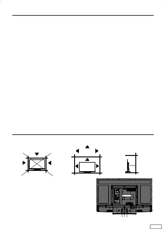
The unit emits heat when in operation. Do not place any covers or blankets on the unit, this may cause overheating.
Do not block ventilation holes, or set up near radiators. Do not place in direct sunshine. When placing on a shelf leave 4 inches (10 cm) free space around the entire unit.
4 inches
4 inches
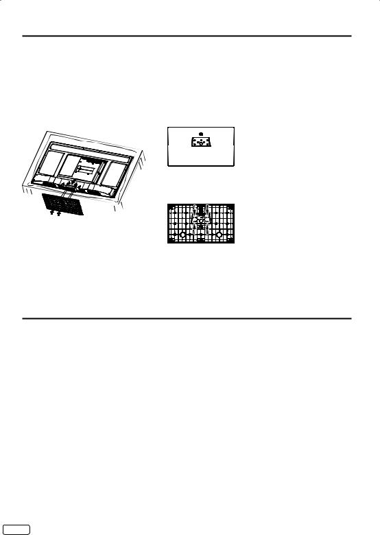
Notes when mounting the TV on a wall
• If the unit is to be mounted on the wall, contact the retailer where you purchased the TV for advice, and have the equipment professionally installed. Incomplete or improper installation may cause injury to you, and/or damage to the TV.
• Bracket holes: To attach a wall mounting bracket (not supplied) attach where indicated in the drawing right.
• This manufacturer recommends professional installation.
• Utilize an appropriate bracket and fasteners, sufficient to accommodate the size and weight of the unit.
• Assure the wall to which the unit is to be mounted will safely support the size and weight of the unit, using the bracket and fasteners you have selected.
• Keep cords and cables connected to this flat panel display out of reach of children.
• To hang the television on a wall, remove these screws and then remove a stand. Before performing work spread cushioning over the base area to lay the TV on.
• Before wall-mounting, please check carefully the location of the TV’s mounting-holes.
Bracket holes
Screws
5 EN
How to attach the stand
NOTE:
•Unplug the AC cord from the wall outlet.
•Before beginning this process, assure that the TV is laid on a clean, safe, and cushioned surface to avoid any damage to the unit.
•Do not touch or press the TV-screen, glass might break under pressure.
Place the TV on its front onto a table.
Align the stand’s bottom-plate (supplied) as seen here.
It will fit in only one direction.
Hold the unit and attach the stand slowly, as shown in Figure 1.
LCD PANEL FRONT
Figure 1
Figure 2
Finally secure the bottom-plate with 4 screws (supplied) (4x16mm(5/32 x 5/8 inches)) as indicated by the arrows in Figure 2.
• Be sure to follow the instructions. Insufficient tightening or incorrect installation of the stand will not support your unit correctly, and could result in damage or injury from tip-over.
How to remove the stand
When you transport this product, remove the stand and pack flat against the back of the unit in the carton. To remove the stand, perform these steps in reverse order.
For wall mounting, the base must be removed. To disconnect the base/stand remove the 3 screws from the back (see page 5).
EN 6
Features
•Integrated Digital Tuner - You can view digital broadcasts without using a Digital TV Set-Top Box.
•Closed Caption Decoder With Full Text Mode - Displays text captions or full screen text on the screen for hearing impaired viewers.
•Picture Adjustments Using The Remote Control - The On-Screen display allows precise remote control adjustment of BRIGHTNESS, CONTRAST, COLOR, TINT and SHARPNESS.
•Programmable TV Sleep Timer - Operable from the remote control, the TV can be programmed for up to 120 minutes to turn off automatically.
•V-Chip - The V-Chip function can read the rating of a broadcast program or movie content if the program is encoded with this information. V-Chip will allow you to set a restriction level.
•Digital Audio Jack (Coaxial) - When a component with a built-in Dolby Digital decoder is connected, Dolby Digital sound can produce the effect of being in a movie theater or a concert hall.
•HDMI/Component Video Jacks - A VCR, DVD player, satellite receiver or other audio/video component can be connected to this unit.
•On-Screen 3 Languages Display - You can select one of 3 languages, English, French or Spanish for onscreen programming.
*Manufactured under license from Dolby Laboratories. Dolby and the double-D symbol are trademarks of Dolby Laboratories.
*The terms HDMI and HDMI High-Definition Multimedia Interface, and the HDMI Logo are trademarks or registered trademarks of HDMI Licensing LLC in the United States and other countries.
Power source
TO USE AC POWER SOURCE
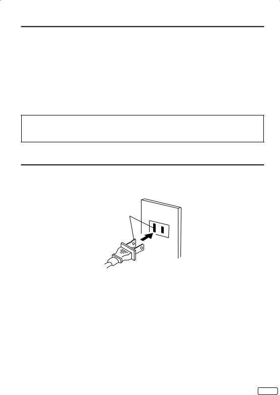
Use the AC polarized line cord provided for operation on AC. Insert the AC cord plug into a standard 120V 60Hz polarized AC outlet.
AC Outlet
Wider Hole and Blade
Polarized AC Cord Plug
(One blade is wider than the other.)
NOTE:
• Never connect the AC line cord plug to other than the specified voltage (120V 60Hz). Use the attached power cord only.
• If the polarized AC cord does not fit into a non-polarized AC outlet, do not attempt to file or cut the blade. It is the user’s responsibility to have an electrician replace the obsolete outlet.
• If you cause a static discharge when touching the unit and the unit fails to function, simply unplug the unit from the AC outlet and plug it back in. The unit should return to normal operation.
7 EN
Contents |
|
Before using your unit |
|
IMPORTANT SAFETY INSTRUCTIONS |
...........3 |
SAFETY PRECAUTIONS ................................. |
5 |
How to attach the stand .................................... |
6 |
How to remove the stand .................................. |
6 |
Features............................................................ |
7 |
Power source .................................................... |
7 |
Contents ........................................................... |
8 |
Parts and functions ........................................... |
9 |
Remote control ............................................... |
10 |
Antenna connections ...................................... |
11 |
Cable TV connections..................................... |
11 |
Connections to other equipment..................... |
12 |
TV operation |
|
Starting setup ................................................. |
15 |
TV operation ................................................... |
15 |
Quick guide for menu operation ...................... |
16 |
Convenience functions ................................... |
17 |
Memorizing channels...................................... |
18 |
Checking the digital signal strength ................ |
19 |
Labeling channels........................................... |
19 |
Labeling video inputs ...................................... |
19 |
Setting the V-Chip ........................................... |
20 |
Closed Caption ............................................... |
21 |
CC advanced.................................................. |
21 |
Setting the picture size.................................... |
22 |
Time Shift........................................................ |
23 |
Additional information |
|
Reception disturbances .................................. |
24 |
Troubleshooting .............................................. |
25 |
Specifications ................................................ |
26 |
limited WARRANTY ........................................ |
27 |
EN 8
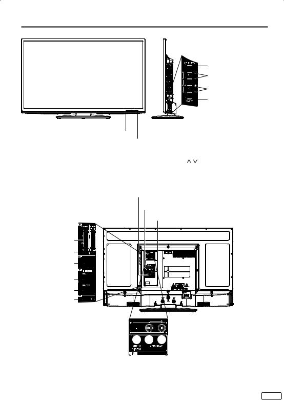
Parts and functions
Front
Remote sensor
Power Indicator
Red : Standby
Green : On
Right side
INPUT/ENTER button
CH (CHANNEL)  /
/ /▲/▼ buttons
VOL (VOLUME) +/–/ / buttons, MENU button


 POWER button
To display the menu screen.
Press hold VOL (VOLUME) +/– simultaneously about 1 second the menu will be appear.
CH (CHANNEL) / buttons, VOL (VOLUME) +/– buttons and INPUT/ENTER button can be used to select the desired setting during the menu screen operations.
|
PC MONITOR IN jack |
|
DIGITAL AUDIO |
|
COAXIAL OUT jack |
Right side Rear |
PC/DVI AUDIO IN jack |
COMPONENT IN jacks |
|
VIDEO2 IN jacks |
|
(VIDEO/AUDIO (L/R)) |
|
ANT. (RF) IN jack |
|
HDMI2 IN jack |
|
HDMI1/DVI IN jack |
|
USB jack |
|
 VAR.(VARIABLE) AUDIO (L/R) OUT jacks


 VIDEO1 IN (VIDEO/AUDIO (L/R)) jacks
9 EN
 Loading...