


OWNER’S MANUAL
R
32” WIDE TFT LCD TELEVISION WITH DIGITAL TUNER
HDLCD3200
ATTENTION
If you purchase a universal remote control from your local retailer, please contact the remote manufacturer for the required programming code.
TV/CABLE MODE SELECTION
When shipped from the factory, the TV/CABLE menu option is set to the “CABLE” (Cable Television) mode. If not using Cable TV, set this menu option to the “TV” position.
IF CONTACT WITH CUSTOMER SERVICE IS REQUIRED
PLEASE HAVE THE MODEL NUMBER READY PRIOR TO THE CALL
CUSTOMER SERVICE – 1-800-289-0980
ORION WEBSITE
FOR INFORMATION ON OUR OTHER PRODUCTS, PLEASE VISIT OUR WEBSITE AT
www.orionsalesinc.com
Before operating the unit, please read this manual thoroughly.
CAUTION: TO REDUCE THE RISK OF ELECTRIC |
SHOCK, DO NOT REMOVE COVER |
(OR BACK). NO USER-SERVICEABLE |
PARTS INSIDE. REFER SERVICING TO |
QUALIFIED SERVICE PERSONNEL. |
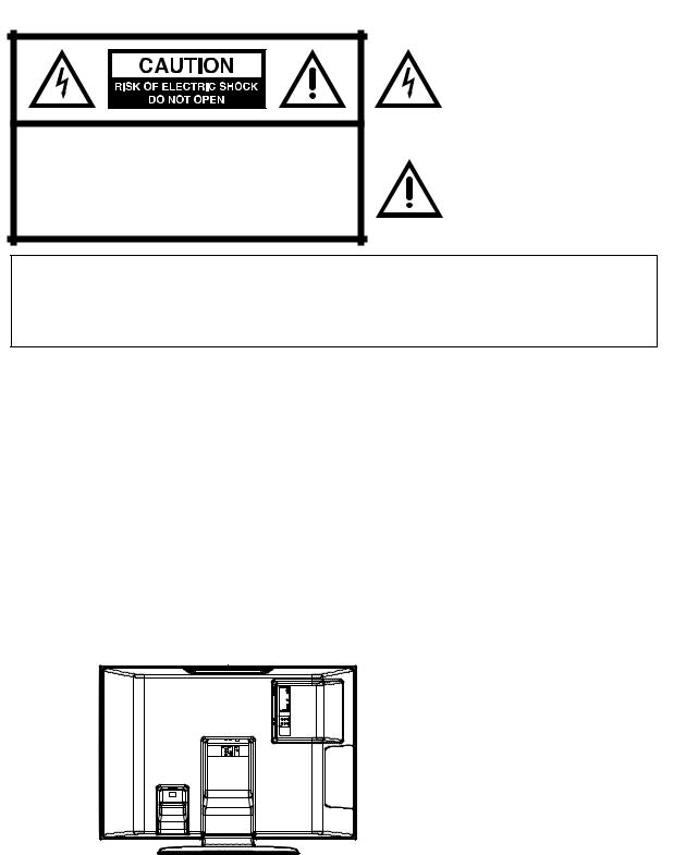
The lightning flash with arrowhead symbol, within an equilateral triangle is intended to alert the user to the presence of uninsulated dangerous voltage within the product's enclosure that may be of sufficient magnitude to constitute a risk of electric shock.
The exclamation point within an equilateral triangle is intended to alert the user to the presence of important operating and maintenance (servicing) instructions in the literature accompanying the appliance.
WARNING: TO PREVENT FIRE OR SHOCK HAZARD, DO NOT EXPOSE THIS APPLIANCE TO RAIN OR MOISTURE.
CAUTION: TO PREVENT ELECTRIC SHOCK DO NOT USE THIS POLARIZED PLUG WITH AN EXTENSION CORD, RECEPTACLE OR OTHER OUTLET UNLESS THE BLADES CAN BE FULLY INSERTED TO PREVENT BLADE EXPOSURE.
WARNING: This equipment has been tested and found to comply with the limits for a Class B digital device, pursuant to Part 15 of the FCC Rules. These limits are designed to provide reasonable protection against harmful interference in a residential installation. This equipment generates, uses and can radiate radio frequency energy and, if not installed and used in accordance with the instructions, may cause harmful interference to radio communications.
However, there is no guarantee that interference will not occur in a particular installation. If this equipment does cause harmful interference to radio or television reception, which can be determined by turning the equipment off and on, the user is encouraged to try to correct the interference by one or more of the following measures:
-Reorient or relocate the receiving antenna.
-Increase the separation between the equipment and receiver.
-Connect the equipment into an outlet on a circuit different from that to which the receiver is connected.
-Consult the dealer or an experienced radio/TV technician for help.
CAUTION: Changes or modifications not expressly approved by the partly responsible for compliance with the FCC Rules could void the user's authority to operate this equipment.
Location of the required Marking
The rating sheet and the safety caution are on the rear of the unit.
2

IMPORTANT SAFETY INSTRUCTIONS
1)Read these instructions.
2)Keep these instructions.
3)Heed all warnings.
4)Follow all instructions.
5)Do not use this apparatus near water.
6)Clean only with dry cloth.
7)Do not block any ventilation openings. Install in accordance with the manufacturer's instructions.
8)Do not install near any heat sources such as radiators, heat registers, stoves, or other apparatus (including amplifiers) that produce heat.
9)Do not defeat the safety purpose of the polarized or grounding-type plug. A polarized plug has two blades with one wider than the other. A grounding type plug has two blades and a third grounding prong. The wide blade or the third prong are provided for your safety. If the provided plug does not fit into your outlet, consult an electrician for replacement of the obsolete outlet.
10)Protect the power cord from being walked on or pinched particularly at plugs, convenience receptacles, and the point where they exit from the apparatus.
11)Only use attachments/accessories specified by the manufacturer.
12) |
Use only with the cart, stand, tripod, bracket, or table specified by the |
PORTABLE CART WARNING |
|
manufacturer, or sold with the apparatus. When a cart is used, use caution |
(symbol provided by RETAC) |
|
|
|
|
when moving the cart/apparatus combination to avoid injury from tip-over. |
|
13) |
Unplug this apparatus during lightning storms or when unused for long |
|
|
periods of time. |
|
14) |
Refer all servicing to qualified service personnel. Servicing is required when |
S3126A |
|
the apparatus has been damaged in any way, such as power-supply cord or |
|
|
|
plug is damaged, liquid has been spilled or objects have fallen into the apparatus, the apparatus has been exposed to rain or moisture, does not operate normally, or has been dropped.
15)Apparatus shall not be exposed to dripping or splashing and that no objects filled with liquids, such a vases, shall be placed on the apparatus.
16)An outside antenna system should not be located in the vicinity of overhead power lines or other electric light or power circuits, or where it can fall into such power lines or circuits. When installing an outside antenna system, extreme care should be taken to keep from touching such power lines or circuits, as contact with them might be fatal.
17)Do not overload wall outlets and extension cords, as this can result in a risk of fire or electric shock.
18)Do not push objects through any openings in this unit, as they may touch dangerous voltage points or short out parts that could result in fire or electric shock. Never spill or spray any type of liquid into the unit.
3
IMPORTANT SAFETY INSTRUCTIONS
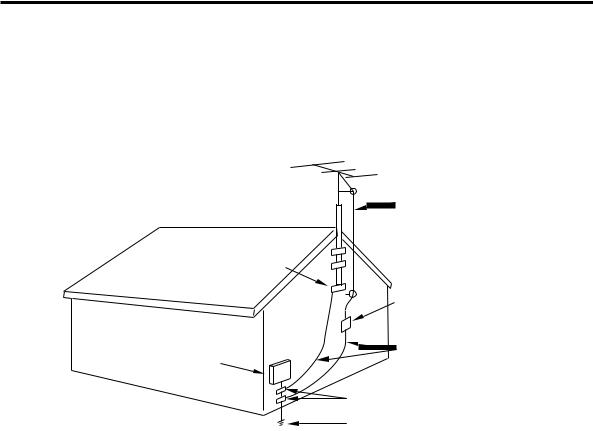
19)If an outside antenna or cable system is connected to the unit, be sure the antenna or cable system is grounded to provide some protection against voltage surges and built-up static charges, Section 810 of the National Electrical Code, ANSI/NFPA 70, provides information with respect to proper grounding of the mast and supporting structure, grounding of the lead-in wire to an antenna discharge unit, size of grounding conductors, location of antenna discharge unit, connection to grounding electrodes, and requirements for the grounding electrode.
EXAMPLE OF ANTENNA GROUNDING AS PER THE
NATIONAL ELECTRICAL CODE
|
ANTENNA LEAD |
|
|
IN WIRE |
|
GROUND |
|
|
CLAMP |
|
|
|
ANTENNA |
|
|
DISCHARGE UNIT |
|
|
(NEC SECTION 810-20) |
|
ELECTRIC SERVICE |
GROUNDING CONDUCTORS |
|
(NEC SECTION 810-21) |
||
EQUIPMENT |
||
|
||
|
GROUND CLAMPS |
|
NEC-NATIONAL ELECTRICAL CODE |
POWER SERVICE GROUNDING |
|
ELECTRODE SYSTEM |
||
S2898A |
||
(NEC ART 250, PART H) |
||
|
20)When replacement parts are required, be sure the service technician uses replacement parts specified by the manufacturer or those that have the same characteristics as the original part.
Unauthorized substitutions may result in fire, electric shock or other hazards.
21)Upon completion of any service or repairs to this unit, ask the service technician to perform safety checks to determine that the unit is in proper operating condition.
22)When you connect the product to other equipment, turn off the power and unplug all of the equipment from the wall outlet. Failure to do so may cause an electric shock and serious personal injury. Read the owner's manual of the other equipment carefully and follow the instructions when making any connections.
23)Reduce the volume to the minimum level before you turn on the product. Otherwise, sudden high volume sound may cause hearing or speaker damage.
24)Do not allow the product to output distorted sound for an extended period of time. It may cause speaker overheating and fire.
25)This reminder is provided to call the cable TV system installer’s attention to Article 820-40 of the NEC that provides guidelines for proper grounding and, in particular, specifies that the cable ground shall be connected to the grounding system of the building, as close to the point of cable entry as practical.
4
IMPORTANT SAFETY INSTRUCTIONS
CONDENSATION
Moisture will form in the operating section of the player if the player is brought from cool surroundings into a warm room or if the temperature of the room rises suddenly. When this happens, player's performance will be impaired. To prevent this, let the player stand in its new surroundings for about an hour before switching it on, or make sure that the room temperature rises gradually.
Condensation may also form during the summer if the player is exposed to the breeze from an air conditioner. In such cases, change the location of the player.
HOW TO HANDLE THE LCD PANEL
•Do not press hard or jolt the LCD panel. It may cause the LCD panel glass to break and injury may occur.
•If the LCD panel is broken, make absolutely sure that you do not touch the liquid in the panel. This may cause skin inflammation.
If the liquid gets in your mouth, immediately gargle and consult with your doctor. Also, if the liquid gets in your eyes or touches your skin, consult with your doctor after rinsing for at least 15 minutes or longer in clean water.
Possible Adverse Effects on LCD Panel: If a fixed (non-moving) pattern remains on the LCD Panel for long periods of time, the image can become permanently engrained in the LCD Panel and cause subtle but permanent ghost images. This type of damage is NOT COVERED BY YOUR WARRANTY. Never leave your LCD Panel on for long periods of time while it is displaying the following formats or images:
•Fixed Images, such as stock tickers, video game patterns, TV station logos, and websites.
•Special Formats that do not use the entire screen. For example, viewing letterbox style (16:9) media on a normal (4:3) display (black bars at top and bottom of screen); or viewing normal style (4:3) media on a widescreen (16:9) display (black bars on left and right sides of screen).
The following symptoms are not signs of malfunction but technical limitation. Therefore we disclaim any responsibility for these symptoms.
•LCD Panel are manufactured using an extremely high level of precision technology, however sometimes parts of the screen may be missing picture elements or have luminous spots.
This is not a sign of a malfunction.
•Do not install the LCD Panel near electronic equipment that is susceptible to electromagnetic waves. Some equipment placed too near this unit may cause interference.
•Effect on infrared devices – There may be interference while using infrared devices such as infrared cordless headphones.
SAFETY PRECAUTIONS
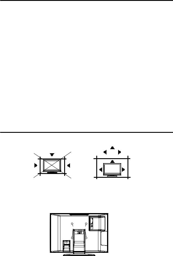
The unit emits heat when in operation. Do not place any covers or blankets on the unit, this may cause overheating.
Do not block ventilation holes, or set up near radiators. Do not place in direct sunshine. When placing on a shelf leave 10 cm (4 inches) free space around the entire unit.
10cm
Notes when mounting the LCD TV on a wall
•When installing the unit on a wall, allow at least 6 cm (2 1/2 inches) clearance between the rear of the LCD TV and the wall. Clearance of less than 6 cm (2 1/2 inches) will obstruct the vents and may cause the interior of the unit to overheat, resulting in damage to the unit.
•If the unit is to be mounted on the wall, contact the retailer where you purchased the LCD TV for advice, and have the equipment professionally installed. Incomplete or improper installation may cause injury to you and/or the LCD TV.
•Bracket holes: To attach a wall mounting bracket (not supplied) here, remove the screws.
Bracket holes
5

Contents
PREPARATIONS |
|
IMPORTANT SAFETY INSTRUCTIONS ....................................... |
3 |
SAFETY PRECAUTIONS ............................................................. |
5 |
Contents ........................................................................................ |
6 |
Features ........................................................................................ |
7 |
Power source ................................................................................ |
7 |
Parts and functions ....................................................................... |
8 |
Remote control .............................................................................. |
9 |
Antenna connections................................................................... |
10 |
Cable TV connections ................................................................. |
11 |
Connections to other equipment ................................................. |
12 |
Setting the language ................................................................... |
17 |
OPERATION |
|
Memorizing channels .................................................................. |
18 |
TV operation ................................................................................ |
20 |
Labeling channels ....................................................................... |
22 |
Selecting the video input source ................................................. |
23 |
Labeling the video input source .................................................. |
23 |
Setting the V-Chip ....................................................................... |
24 |
Closed Caption ............................................................................ |
27 |
CC advanced .............................................................................. |
28 |
Setting the picture size ................................................................ |
29 |
Setting the picture scroll .............................................................. |
31 |
Selecting the cinema mode ......................................................... |
32 |
Using the aspect feature ............................................................. |
32 |
Adjusting the picture preference ................................................. |
33 |
Picture control adjustment........................................................... |
33 |
Selecting the color temperature .................................................. |
34 |
Adjusting the backlighting ........................................................... |
34 |
Resetting your picture adjustments ............................................. |
35 |
Selecting Stereo/Second Audio Program (SAP) ......................... |
36 |
Sound control adjustment ........................................................... |
36 |
Selecting the HDMI audio input source ....................................... |
37 |
Selecting the audio language ...................................................... |
37 |
Selecting the digital output .......................................................... |
38 |
Resetting your audio adjustments ............................................... |
38 |
Checking the Digital-signal strength ............................................ |
39 |
Setting the auto shut off .............................................................. |
40 |
Picture/Audio control adjustment in the PC mode ....................... |
41 |
OTHERS |
|
Reception disturbances............................................................... |
43 |
Troubleshooting ........................................................................... |
44 |
Specifications .............................................................................. |
45 |
LIMITED WARRANTY ................................................................. |
46 |
6
Features
•Integrated Digital Tuner - You can view digital broadcasting without using a Digital TV Set-Top Box.
•Closed Caption Decoder With Full Text Mode - Displays text captions or full screen text on the screen for hearing impaired viewers.
•Picture Adjustments Using The Remote Control - The On-Screen display allows precise remote control adjustment of BRIGHTNESS, CONTRAST, COLOR, TINT and SHARPNESS.
•Programmable TV Sleep Timer - Operable from the remote control, the LCD TV can be programmed for up to 120 minutes to turn off automatically.
•V-Chip - The V-Chip function can read the rating of a broadcast program or movie content if the program is
encoded with this information. V-chip will allow you to set a restriction level.
•Digital Audio Jack (Coaxial) - When a component with a built-in Dolby Digital decoder is connected, Dolby Digital sound can produce the effect of being in a movie theater or a concert hall.
•S-Video/Component Video Jacks - A VCR, DVD player, satellite receiver or other audio/video component can be connected to this unit.
•Video Input Jacks - This unit is equipped 3 types of video input jacks. The component video in jacks and S-video in jack enable you to watch the DVD player or the video devices with high quality picture.
•On-Screen 3 Language Display - You can select one of 3 languages, English, Spanish or French for onscreen programming.
*Manufactured under license from Dolby Laboratories. “Dolby” and the double-D symbol are trademarks of Dolby Laboratories.
Power source
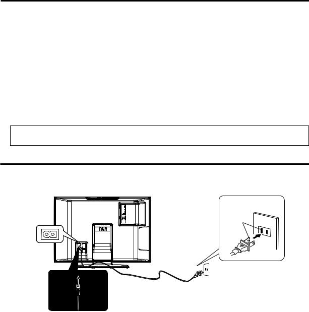
TO USE AC POWER
1.Connect the AC cord plug into this unit's AC IN jack.
2.Connect the AC cord into an AC outlet.
AC Outlet
Wider Hole
and Blade
AC 120V, 60Hz
AC cord (supplied)
NOTES:
•Please make sure to insert the cord securely at both the LCD TV and the wall outlet.
•The AC cord has a grounding-type AC line plug. If the supplied AC cord does not match you AC outlet, contact a qualified electrician, do not defeat the purpose of a grounding plug.
WARNING:
•DO NOT CONNECT THIS UNIT TO THE POWER USING ANY DEVICE OTHER THAN THE SUPPLIED AC CORD. THIS COULD CAUSE FIRE, ELECTRICAL SHOCK, OR DAMAGE.
•DO NOT USE WITH A VOLTAGE OTHER THAN THE POWER VOLTAGE DISPLAYED. THIS COULD CAUSE FIRE, ELECTRICAL SHOCK, OR DAMAGE.
CAUTION:
•WHEN THIS UNIT IS NOT USED FOR A LONG TIME, (E.G., AWAY ON A TRIP) IN THE INTEREST OF SAFETY, BE SURE TO UNPLUG IT FROM THE AC OUTLET.
•DO NOT PLUG/UNPLUG THE PLUG WHEN YOUR HANDS ARE WET. THIS MAY CAUSE ELECTRICAL SHOCK.
•IF YOU NEED TO REPLACE THE SUPPLIED AC ADAPTER OR AC CORD, THE SPECIFIED ONE IS
RECOMMENDED. CONTACT CUSTOMER SERVICE AT 1-800-289-0980. |
7 |
|

Parts and functions
Top
CHANNEL ▲/▼ buttons MENU button INPUT button
VOLUME +/– buttons
POWER button
To display the menu screen.
Press MENU button to display the menu screen.
CHANNEL ▲/▼ buttons and VOLUME +/– buttons can be used to select the desired setting during the menu screen operations.
Front |
Rear |
Remote sensor
|
COAXIAL DIGITAL |
|
AUDIO OUT jack |
POWER indicator |
RF (ANT) IN jacks |
|
|
|
AV1 IN jacks |
Left side
PC IN jacks
PC/HDMI AUIDIO IN jacks
HDMI IN jacks
COMPONENT IN jacks
AV2 IN jacks
8
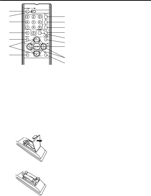
Remote control
1 |
|
2 |
8 |
3 |
9 |
|
10 |
4 |
11 |
|
|
5 |
12 |
|
|
|
13 |
6 |
14 |
7 |
15 |
|
|
|
16 |
1.POWER Button - Used to turn the LCD TV.
2.SLEEP Button - To set the LCD TV to turn off after a preset amount of time, use the SLEEP button on the remote control.
3.Direct Channel Selection Buttons (0-9) - Allows direct access to any channel of the LCD TV.
4.– Button -This button is the “–” button used when selecting digital channels.
5.RESET Button - Press to reset the On-Screen picture adjustments to their factory preset positions.
6.CH (CHANNEL) /
/ /CURSOR ▲ / ▼ Buttons -
Used to operate the menu functions of the LCD TV, and to change the channels of the LCD TV.
7.MENU Button - Use to display the On-Screen menu function.
8.MUTE Button - To turn off the sound, press this button once. The LCD TV will be silenced and the symbol “MUTE” will appear on the screen. The muting feature can be released by pressing the MUTE button again or one of the VOL (VOLUME) + or – buttons.
9.DISPLAY Button - When you press this button, the current information will be displayed on a screen. To remove the display from the screen, press this button again.
10.PICTURE SIZE Button - Press to display PICTURE SIZE menu.
11.INPUT SELECT Button - Press to display SOURCE SELECTION menu.
12.QUICK VIEW Button - This button allows you to go back to the previous channel selected by just pressing the QUICK VIEW button. Press this button again to return to the channel you were watching.
13.CLOSED CAPTION Button - Displays text captions or full screen text on the screen for hearing impaired viewers.
14.ENTER Button - Use to enter or select information for On-Screen operations.
15.VOL (VOLUME) + / – / CURSOR  /
/  Buttons -
Used to operate the menu functions of the LCD TV. Press the  button to increase, or the
  button to decrease the sound level.
16.EXIT Button - Press to remove setup menu.
Before using the remote control, batteries must first be installed.
HOW TO INSTALL BATTERIES
1. Open the battery compartment cover.
2. Install two “AA” batteries (supplied).
3. Replace the battery compartment cover.
Use two “AA” size batteries. The batteries may last approximately one year depending on how much the remote control is used. For best performance, it is recommended that batteries should be replaced on a yearly basis, or when the remote operation becomes erratic. Do not mix old and new batteries or different types.
BATTERY PRECAUTIONS
These precautions should be followed when using batteries in this device:
•Use only the size and type of batteries specified.
•Be sure to follow the correct polarity when installing the batteries as indicated in the battery compartment. Reversed batteries may cause damage to the device.
•Do not mix different types of batteries together (e.g. Alkaline and Carbon-zinc) or old batteries with fresh ones.
•If the device is not to be used for a long period of time, remove the batteries to prevent damage or injury from possible battery leakage.
•Do not try to recharge batteries not intended to be recharged; they can overheat and rupture. (Follow battery manufacturer's directions.)
9
Antenna connections
If you are using an indoor or outdoor antenna, follow the instructions below that correspond to your antenna system. If you are using a Cable TV service, see page 11 for Cable TV connections.
Combination VHF/UHF Antenna (Single 75 ohm cable or 300 ohm twin-lead wire)
|
Connect the 75 ohm cable from the combination |
Antenna |
VHF/UHF antenna to the antenna jack. |
Antenna |
|
Jack |
Jack |
|
If your combination VHF/UHF antenna has a 300 |
|
ohm twin-lead wire, the use of the 300-75 ohm |
|
matching transformer may be necessary. |
ANT |
ANT |
|
75 ohm |
300-75 ohm |
|
Coaxial |
||
Matching |
||
Cable |
||
Transformer |
||
|
Combination VHF/UHF Antenna (Separate VHF and UHF 300 ohm twin-lead wires)
Antenna
Jack
ANT
Combiner
Connect the UHF 300 ohm twin-lead wire to the Combiner (not supplied). Connect the VHF 300 ohm twin-lead wire to the 300-75 ohm Matching Transformer. Attach the Transformer to the Combiner, then attach the Combiner to the Antenna Jack.
UHF 300 ohm
VHF 300 ohm
300-75 ohm Matching Transformer
Separate VHF/UHF Antennas (75 ohm VHF cable and 300 ohm UHF twin-lead wires)
|
Connect the VHF 75 ohm cable and UHF 300 ohm |
Antenna |
twin-lead wire to the Combiner (not supplied). |
Jack |
Attach the Combiner to the Antenna Jack. |
|
ANT |
Combiner |
|
UHF 300 ohm |
|
|
VHF 75 ohm |
10
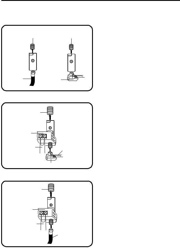
Cable TV connections
This TV has an extended tuning range and can tune most cable channels without using a Cable TV Converter box. Some cable companies offer “premium pay channels” where the signal is scrambled. Descrambling these signals for normal viewing requires the use of a descrambler device which is generally provided by the Cable TV company.
FOR SUBSCRIBERS TO BASIC CABLE TV SERVICE
Antenna
Jack
ANT
For basic Cable TV service not requiring a Converter/ Descrambler box, connect the 75 ohm Coaxial Cable directly to the Antenna Jack on the back of the TV.
75 ohm Coaxial Cable
FOR SUBSCRIBERS TO SCRAMBLED CABLE TV SERVICE
If you subscribe to a Cable TV service which requires the use of a Converter/Descrambler box, connect the incoming 75 ohm Coaxial Cable to the Converter/Descrambler box. Using another 75 ohm Coaxial Cable, connect the output jack of the Converter/Descrambler box to the Antenna Jack on the TV. Follow the connections shown below. Set the TV to the output channel of the Converter/Descrambler box (usually channel 3 or 4) and use the Converter/Descrambler box to select channels.
Incoming |
|
|
75 ohm |
|
Antenna |
Cable TV |
|
Jack |
Cable |
Converter/ |
75 ohm Cable to TV |
|
|
|
|
Descrambler |
|
FOR SUBSCRIBERS TO UNSCRAMBLED BASIC CABLE TV SERVICE WITH SCRAMBLED PREMIUM CHANNELS
If you subscribe to a Cable TV service in which basic channels are unscrambled and premium channels require the use of a Converter/Descrambler box, you may wish to use a signal Splitter and an A/B Switch box (available from the Cable TV company or an electronics supply store). Follow the connections shown below. With the switch in the “B” position, you can directly tune any nonscrambled channels on your TV. With the switch in the “A” position, tune your TV to the output of the Converter/Descrambler box (usually channel 3 or 4) and use the Converter/Descrambler box to tune scrambled channels.
Incoming |
Converter/ |
|
|
75 ohm |
|
|
|
Descrambler |
|
Antenna |
|
Cable TV |
|
|
Jack |
Cable |
A/B Switch |
A |
75 ohm Cable to TV |
Splitter |
B |
||
|
|
|
11
Connections to other equipment
The exact arrangement you use to interconnect various video and audio components to the LCD TV is dependent on the model and features of each component. Check the Owner's Manual provided with each component for the location of video and audio inputs and outputs.
The connection diagrams below are offered as suggestions. You may need to modify them to accommodate your particular assortment of components. The diagrams are intended to show component video and audio interconnections only.
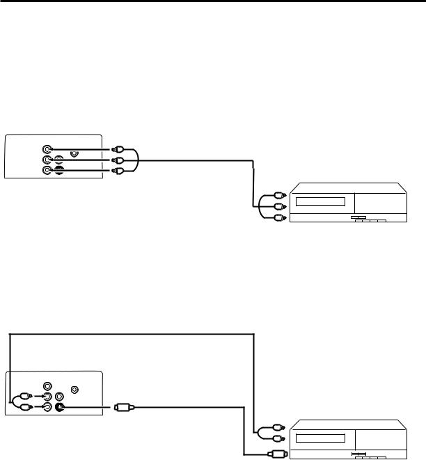
To connect the LCD TV to a VCR
Rear of the LCD TV
To AUDIO/VIDEO IN 1 (or 2)
Audio/Video cord (not supplied)
To Audio/Video OUT
To connect the LCD TV to a VCR with an S-Video cord
If you connect a VCR with a S-VIDEO cord to the S-VIDEO IN jack on the rear of the LCD TV, you must also connect the audio cords to the AUDIO IN jacks on the rear of the LCD TV. The S-VIDEO cord only carries the video signal. The audio signal is separate.
Audio cord (not supplied)
Rear of the LCD TV
To S-VIDEO IN 1
To Audio OUT
S-Video cord (not supplied)
To AUDIO IN 1
To S-Video OUT
NOTE:
When the S-video cord and the video cord are connected to each jack at the same time, the S-video cord takes precedence over the video cord.
12
Connections to other equipment
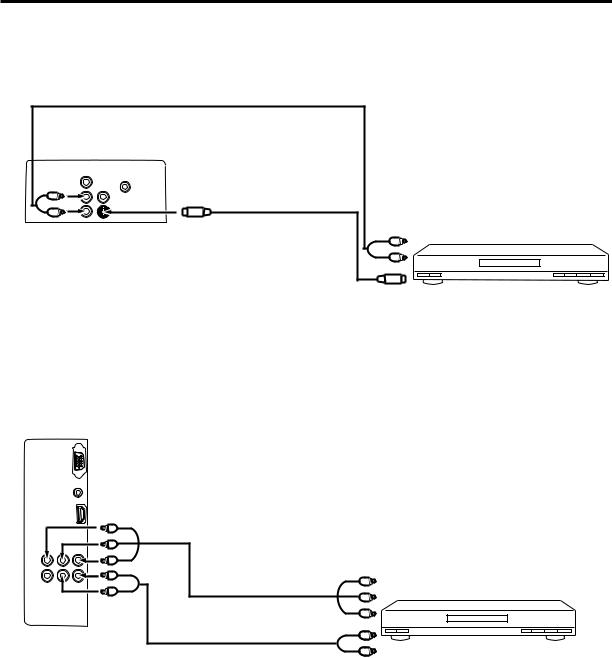
To connect the LCD TV to a DVD player/Satellite receiver
If your DVD player or Satellite receiver has a S-Video out jack, connect cords as shown.
Audio cord (not supplied)
Rear of the LCD TV |
|
|
|
To S-VIDEO IN 1 |
|
To AUDIO IN 1 |
S-Video cord (not supplied) |
To Audio OUT |
|
||
|
|
To S-Video OUT
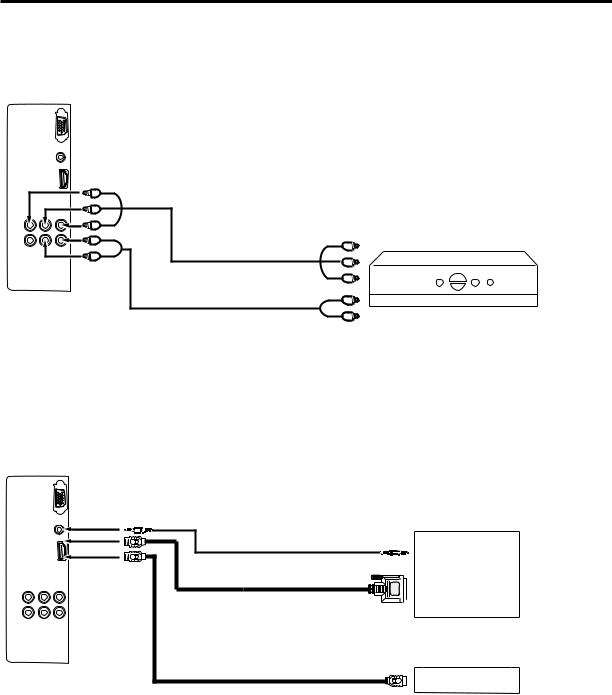
To connect the LCD TV to a DVD player with component video
If your DVD player has component video out jacks, connect your LCD TV to a DVD player using a component video cord. It can greatly enhance picture quality and performance.
Left side of the LCD TV
To COMPONENT IN |
|
|
To Component OUT |
Video cord (not supplied) |
Y |
To AUDIO |
PB |
IN 2 |
PR |
Audio cord (not supplied) |
|
To Audio OUT
NOTE:
Component Video inputs of the unit are for use with a device which outputs 480i/1080i interlaced signals and 480p/720p progressive signals.
13
Connections to other equipment
To connect the LCD TV to a DTV receiver/set-top box
If you connect a DTV receiver/set-top box, connect your LCD TV to a DTV receiver/set-top box using a component video cord.
Left side of the LCD TV
To COMPONENT IN |
|
|
To Component OUT |
Video cord (not supplied) |
Y |
To AUDIO |
PB |
IN 2 |
PR |
Audio cord (not supplied) |
|
|
To Audio OUT |
To connect the LCD TV to a HDMI or a DVI device
The HDMI input receives digital audio and uncompressed video from a HDMI device or uncompressed digital video from a DVI device.
When you connect to a DVI device with a HDMI-to-DVI adapter cable, it transfers only the video signal. Separate analog audio cords are required.
Left side of the LCD TV
Audio cord (not supplied)
HDMI - to - DVI adapter cable (HDMI type A connector)
(not supplied) 

 To DVI output
or
HDMI cable (type A connector)
(not supplied) |
To HDMI out |
|
DVI device
or
HDMI device
NOTE:
You must choose an appropriate setting for each connection (see “Selecting the HDMI audio input source” on page 37).
14
Connections to other equipment
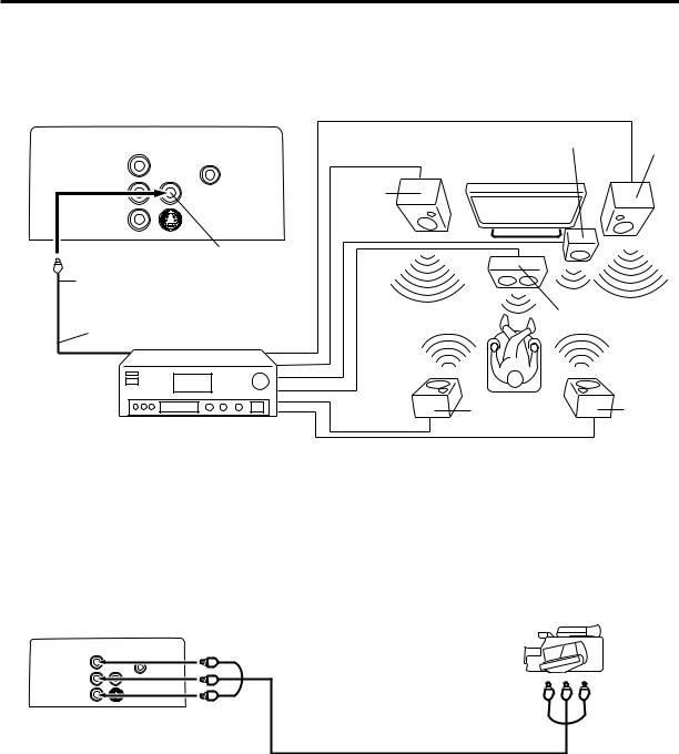
Using an AV Amplifier with built-in digital surround
If you are using an Amplifier with built-in digital surround sound, you can enjoy various audio systems including Dolby Digital Surround audio that sounds just like the movie.
Connect an AV amplifier with built-in Dolby Digital decoder, or etc. as shown below.
Left side of the LCD TV Front
Speaker Subwoofer (Right)
TV
Front
Speaker
(Left)
Coaxial Digital Audio Output
Coaxial digital cable (not supplied)
To Coaxial Digital Audio Input
AV Amplifier with built-in digital surround decoder as listed above
Center Speaker
Surround |
Surround |
Speaker (Left) |
Speaker |
|
(Right) |
NOTE:
This unit will not work in conjunction with DTS audio. There will be no sound output if connected to an AV amplifier with a built-in DTS decoder.
To connect the LCD TV to a camcorder
To playback from a camcorder, connect the camcorder to the LCD TV as shown.
Left of the LCD TV
To AUDIO/VIDEO IN 1 (or 2)
To Audio/Video OUT
Audio/Video cord (not supplied)
15
 Loading...