

Page 1

7. Flow Chart of Troubleshooting
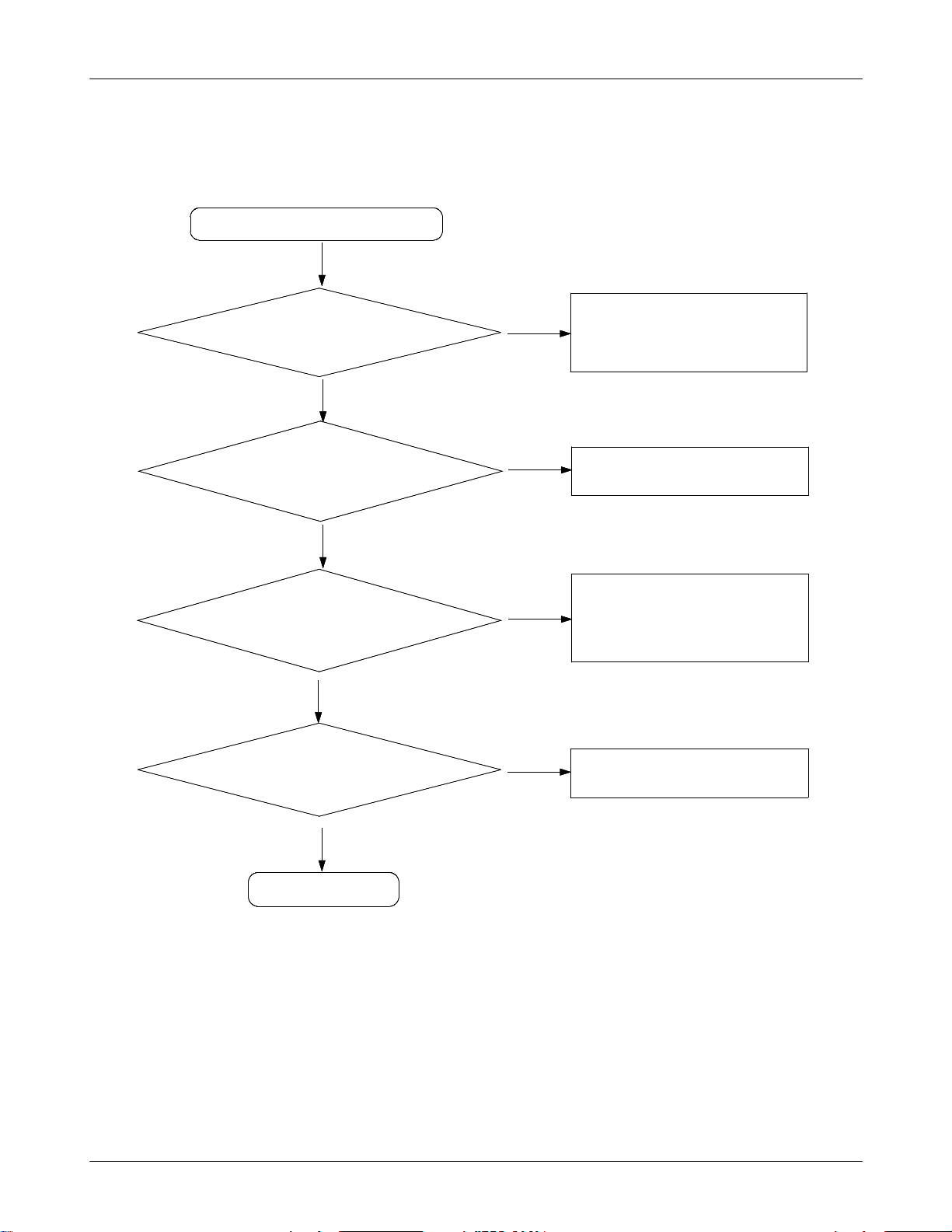
7-1. Power On
' Power On ' does not work
Yes
Check the Battery Voltage
is more than 3.4V
Yes
C408(VINT) = 2.7V?
Yes
Check the Clock at
R402=32KHZ
Yes
C425(+VDD_IO_LOW) &
C424(+VDD_IO_HIGH) = "H"?
Yes
No
Change the Battery
No
Check the PMU related to VINT
No
Resolder OSC400
No
Check the related circuit
C401(+VDD_GSM_CORE)
=1.8V?
Yes
Check for the clock at C312
= 26MHz
Yes
Check the initial operation
Yes
END
SAMSUNG Proprietary-Contents may change without notice
This Document can not be used without Samsung's authorization
No
No
7-1
Check the +VDD_GSM_CORE circuit
Check the clock generation circuit
(related to U100)
Page 2

FlowChartofTroubleshooting
FlowChartofTroubleshooting
ONKEYN
ONKEYN
C405
C405
OSC400
OSC400
C411
C411
Typical 3.7V
Typical 3.7V
+VDD_RX_TX
+VDD_RX_TX
+VCC_SYN
+VCC_SYN
+VDD_IMAGE
+VDD_IMAGE
+AVDD_HFA
+AVDD_HFA
+VDD_IO_HIGH
+VDD_IO_HIGH
+VDD_IO_LOW
+VDD_IO_LOW
R402
R402
C407
C407
VBAT
VBAT
+AVDD
+AVDD
V400
V400
R404
R404
C410
C410
C412
C412
C414
C414
C415
C415
C416
C416
C422
C422
C424
C424
C425
C425
C406
C406
C408
C408
BU_RST
R401
R401
POS
POS
BAT400
BAT400
NEG
NEG
29
30
27
31
26
25
26
25
I
I
O
O
C
C
C
C
S
S
S
S
O
O
O
O
24
24
RF2VDD
RF2VDD
23
23
RF12VBAT
RF12VBAT
22
22
RF1VDD
RF1VDD
21
21
D1VDD
D1VDD
20
20
LPD1VBAT
LPD1VBAT
19
19
LPVDD
LPVDD
18
18
HCVBAT
HCVBAT
17
17
HCVDD
HCVDD
16
16
D2VDD
D2VDD
15
15
IOD2VBAT
IOD2VBAT
14
14
IOVDD
IOVDD
13
13
_REC2
_REC2
S
S
A
A
I
I
B
B
C
C
I
I
M
M
12
12
C423
C423
32
28
27
28
Y
Y
C
C
E
E
F
F
E
E
K
K
R
R
N
N
O
O
_
_
C
C
H
H
T
T
Q
Q
S
S
R
R
I
R
I
R
_
_
_
_
10
11
10
11
34
33
36
29
T
T
N
N
I
I
V
V
C
C
H
H
O
O
I
I
M
M
I
I
S
S
9
9
35
30
31
32
34
33
36
35
X
X
T
T
V
V
T
T
E
E
D
D
G
G
A
A
A
A
R
R
A
A
V
V
D
D
H
H
B
A
A
S
S
V
V
U400
U400
C
H
K
C
M
I
S
8
8
B
M
M
D
D
B
B
V
V
C
C
V
V
V
V
C
C
C
1
1
H
H
H
S
S
N
N
K
E
E
R
R
C
R
R
M
M
I
I
M
I
W
W
S
S
_
S
P
_
P
7
6
7
6
SCP
SCP
T
T
V
V
P
P
G
G
P
P
A
A
C
C
H
H
C
C
B
B
C
C
/
/
SCN
SCN
R
R
U
U
C
C
G
G
D3VDD
D3VDD
H
H
C
C
SIMD3VBAT
SIMD3VBAT
SIMVCC
SIMVCC
SIMIOCD
SIMIOCD
SIMCKCD
SIMCKCD
_SIMRSCD
_SIMRSCD
SIMEN
SIMEN
GPO3
GPO3
GPO2
GPO2
GPO1
GPO1
GND
GND
GND
GND
GND
GND
2
2
K
K
GND
GND
N
N
1
1
2
2
E
E
3
3
C
C
NC
NC
R
R
L
A
L
A
K
K
E
E
L
L
C
D
W
C
D
W
R
R
NC
NC
_
S
S
P
C
_
S
S
P
C
1
2
3
5
4
1
2
3
5
4
BU_RST
C409
C409
+VDD_SLEEP
C413
37
37
38
38
39
39
40
40
41
41
42
42
43
43
44
44
45
45
46
46
47
47
48
48
49
49
50
50
51
51
52
52
53
53
54
54
C413
R405
R405
V401
V401
TP400
TP400
+VDD_SLEEP
+VDD_IO_LOW
+VDD_IO_LOW
SIM_VCC
SIM_VCC
SIM400
SIM400
SIM_IO
SIM_IO
1
1
SIM_CLK
SIM_CLK
SIM_RST
SIM_RST
C417
C417
C419
C419
C418
C420
C418
C421
C421
C420
6
6
2
2
5
5
3
3
4
4
G78G
G78G
G
G
G
G
910
910
AUX_ON
AUX_ON
SCL
SCL
SDA
SDA
32KHz_DIGIT
32KHz_DIGIT
PON_TX
PON_TX
REF_ON
REF_ON
SIMRST
SIMRST
SIMCLK
SIMCLK
MIC_BIAS
MIC_BIAS
R406
R406
RSTON
RSTON
IT_PMU
IT_PMU
SIMIO
SIMIO
26M_CLK
26M_CLK
C312
C312
+VDD_IO_HIGH
+VDD_IO_HIGH
R313
R313
R315
R315
+VDD_IO_HIGH
+VDD_IO_HIGH
U302
U302
1
5
1
5
NC
VCC
NC
VCC
2
2
INA
INA
4
4
3
3
OUTY
OUTY
GND
GND
R314
R314
26M_DIGIT
26M_DIGIT
7-2
7-2
SAMSUNG Proprietary-Contents may change without notice
SAMSUNG Proprietary-Contents may change without notice
This Document can not be used without Samsung's authorization
This Document can not be used without Samsung's authorization
Page 3

7-2. Initial
7-2. Initial
Initial Failure
Initial Failure
Yes
Yes
Q300 pin 4 (RSTON) ="H"
Q300 pin 4 (RSTON) ="H"
Yes
Yes
Is UCP200 R214, R215
Is UCP200 R214, R215
OK?
OK?
No
No
No
No
FlowChartofTroubleshooting
FlowChartofTroubleshooting
Check the circuit related to reset
Check the circuit related to reset
Check the UCP200
Check the UCP200
Yes
Yes
Check the 16bit data signal
Check the 16bit data signal
&memoryCE
&memoryCE
Yes
Yes
END
END
7-3
7-3
SAMSUNG Proprietary-Contents may change without notice
SAMSUNG Proprietary-Contents may change without notice
This Document can not be used without Samsung's authorization
This Document can not be used without Samsung's authorization
Page 4

FlowChartofTroubleshooting
FlowChartofTroubleshooting
R13
R13
RFSIG0
RFSIG0
M12
M12
RFSIG1
RFSIG1
M11
M11
RFSIG2
RFSIG2
V5
V5
GPIOA3
GPIOA3
P9
P9
GPIOA4
GPIOA4
L11
L11
GPIOA5
GPIOA5
R11
R11
RFSIG6
RFSIG6
P11
P11
RFSIG7
RFSIG7
T2
T2
GPIOA21
GPIOA21
R2
R2
GPIOA22
GPIOA22
R5
R5
GPIOA23
GPIOA23
U18
U18
RFCLK1
RFCLK1
R17
R17
RFDO1
RFDO1
G1
G1
GPIOA9
GPIOA9
V18
V18
RFEN0
RFEN0
H1
H1
RESET
RESET
V10
V10
MCLK
MCLK
R9
R9
AUXDAC1
AUXDAC1
R8
R8
AUXDAC2
AUXDAC2
V11
V11
AUXDAC3
UCP200
UCP200
AUXDAC3
MICBIAS
MICBIAS
AUXADC1
AUXADC1
AUXADC2
AUXADC2
AUXADC3
AUXADC3
AUXADC4
AUXADC4
AUXADC5
AUXADC5
AUXMICN
AUXMICN
AUXMICP
AUXMICP
GPIOA24
GPIOA24
GPIOA25
GPIOA25
GPIOA26
GPIOA26
GPIOA30
GPIOA30
GPIOA27
GPIOA27
GPIOA28
GPIOA28
SIMCLK
SIMCLK
SIMIO
SIMIO
SIMPWR
SIMPWR
SIMRST
SIMRST
GPIOA17
GPIOA17
GPIOA29
GPIOA29
GPIOA31
GPIOA31
USBCN
USBCN
USBDM
USBDM
USBDP
USBDP
VREF
VREF
HFR1
HFR1
HFR2
HFR2
EAR1
EAR1
EAR2
EAR2
MICN
MICN
MICP
MICP
ANL
ANL
ANR
ANR
FSC
FSC
DCL
DCL
SCL
SDA
SDA
SCL
C217
C217
U14
U14
V12
V12
V8
V8
QN
QN
V7
V7
QP
QP
U8
U8
IN
IN
U7
U7
IP
IP
J1
J1
K1
K1
K2
K2
L1
L1
L2
L2
J17
J17
H18
H18
K15
K15
J15
J15
M18
M18
N18
N18
L17
L17
M17
M17
K18
K18
L18
L18
D13
D13
E11
E11
B13
B13
DD
DD
B14
B14
DU
DU
N1
N1
T1
T1
L9
L9
U17
U17
M14
M14
P8
P8
P6
P6
R6
R6
G17
G17
D15
D15
N14
N14
F17
F17
V2
V2
V3
V3
V4
V4
F14
F14
G14
G14
H11
H11
R207
R207
R208
R208
MODE_SELECT
MODE_SELECT
PON_SW
PON_SW
PON_PA
PON_PA
BT_INT
BT_INT
PON_TX
PON_TX
PON_3587_SYNTH
PON_3587_SYNTH
EXT2
EXT2
DCS
DCS
RF_CLK
RF_CLK
RF_DATA
RF_DATA
RF_EN
RF_EN
RSTEXTn
RSTEXTn
EDGE1_PA
EDGE1_PA
AFC
AFC
RAMP
RAMP
MIC_BIAS_BB
MIC_BIAS_BB
RX_TX_QN
RX_TX_QN
RX_TX_QP
RX_TX_QP
RX_TX_IN
RX_TX_IN
RX_TX_IP
RX_TX_IP
MES_BATT
MES_BATT
VF
VF
TEMP_PRODUCT
TEMP_PRODUCT
EAR_ADC
EAR_ADC
HFR_P
HFR_P
HFR_N
HFR_N
EAR1
EAR1
EAR2
EAR2
MIC_N
MIC_N
MIC_P
MIC_P
C222
C222
C223
C223
FSC
FSC
+VDD_IO_LOW
+VDD_IO_LOW
DCL
DCL
R213
R213
DD
DD
DU
DU
R_CONTROL
R_CONTROL
MELODY_SEL
MELODY_SEL
JACK_EN
JACK_EN
AUX_ON
AUX_ON
END_OF_CHG
END_OF_CHG
AUDIO_SW
AUDIO_SW
SIMCLK
SIMCLK
SIMIO
SIMIO
SIMRST
SIMRST
EXT1
EXT1
CHG_ON
CHG_ON
USBCN
USBCN
USBDM
USBDM
USBDP
USBDP
R205
R205
USB Interface
USB Interface
CLKBURST
CLKBURST
ANL
ANL
ANR
ANR
DAI & Bluetooth data Interface
DAI & Bluetooth data Interface
R203
R203
100K
100K
IT_PMU
IT_PMU
M_INT
M_INT
KEY_LED_ON
KEY_LED_ON
D_REF_CLK
D_REF_CLK
+VDD_IO_HIGH
+VDD_IO_HIGH
R215
R215
R214
R214
SCL
SCL
SDA
SDA
+VDD_IO_LOW
+VDD_IO_LOW
+VDD_IO_LOW
+VDD_IO_HIGH
+VDD_IO_HIGH
R309
R309
LCD_RESET
LCD_RESET
S_RST
S_RST
SAMSUNG Proprietary-Contents may change without notice
SAMSUNG Proprietary-Contents may change without notice
This Document can not be used without Samsung's authorization
This Document can not be used without Samsung's authorization
+VDD_IO_LOW
Q300
Q300
7-4
7-4
4
4
5
5
6
6
3
3
2
2
1
1
LEVEL SHIFT
LEVEL SHIFT
+VDD_IMAGE
+VDD_IMAGE
R307
R307
RSTON
RSTON
S_RST_IMAGE
S_RST_IMAGE
Page 5

FlowChartofTroubleshooting
FlowChartofTroubleshooting
7-5
7-5
SAMSUNG Proprietary-Contents may change without notice
SAMSUNG Proprietary-Contents may change without notice
This Document can not be used without Samsung's authorization
This Document can not be used without Samsung's authorization
Page 6
FlowChartofTroubleshooting
FlowChartofTroubleshooting
7-3. Charging Part
7-3. Charging Part
Abnormal charging part
Abnormal charging part
Check the U502 pin 1
Check the U502 pin 1
U502 pin 5 = "L"?
U502 pin 5 = "L"?
>4.9V
>4.9V
Yes
Yes
Yes
Yes
No
No
No
No
Check the circuit related to
Check the circuit related to
V_EXT_CHARGE
V_EXT_CHARGE
Resolder or replace U502
Resolder or replace U502
Yes
Yes
U502 pin 3 = "L"?
U502 pin 3 = "L"?
Yes
Yes
Check the U502 pin 10
Check the U502 pin 10
≒4.2V
≒4.2V
Yes
Yes
END
END
No
No
No
No
Check the circuit related to
Check the circuit related to
AUX_ON signal
AUX_ON signal
Resolder or replace U502
Resolder or replace U502
7-6
7-6
SAMSUNG Proprietary-Contents may change without notice
SAMSUNG Proprietary-Contents may change without notice
This Document can not be used without Samsung's authorization
This Document can not be used without Samsung's authorization
Page 7

V_EXT_CHARGE
V_EXT_CHARGE
5.0V
5.0V
+VBUS
+VBUS
AUX_ON
AUX_ON
CHG_ON
CHG_ON
C504
C504
C503 ZD501
C503 ZD501
+VDD_IO_HIGH
+VDD_IO_HIGH
R511
R511
C506
C506
FlowChartofTroubleshooting
FlowChartofTroubleshooting
Typical 3.7V
Typical 3.7V
VBAT
VBAT
R510
R510
ZD500
U502
U502
1
1
CRDL
CRDL
2
2
USB
USB
3
3
_PPR
_PPR
4
4
_CHG
_CHG
5
5
_EN
_EN
10
10
BAT
BAT
9
9
ICDL
ICDL
8
8
GND
GND
7
7
USBON
USBON
6
6
IMIN
IMIN
GND
GND
11
11
R515
R515
ZD500
R512
R512
R514
R514
BATTERY CHARGING
BATTERY CHARGING
C505
C505
Typical 1.4V
Typical 1.4V
MES_BATT
MES_BATT
USB_CHG_ONEND_OF_CHG
USB_CHG_ONEND_OF_CHG
7-7
7-7
SAMSUNG Proprietary-Contents may change without notice
SAMSUNG Proprietary-Contents may change without notice
This Document can not be used without Samsung's authorization
This Document can not be used without Samsung's authorization
Page 8

FlowChartofTroubleshooting
FlowChartofTroubleshooting
7-4. Sim Part
7-4. Sim Part
Phone can't access SIM Card
Phone can't access SIM Card
SIM400 pin 1,5 = "H"?
SIM400 pin 1,5 = "H"?
After Power ON,
After Power ON,
Check SIMCLK Signal on
Check SIMCLK Signal on
pin3 of SIM400 in a few
pin3 of SIM400 in a few
Yes
Yes
Yes
Yes
No
No
No
No
Check the sim charge pump
Check the sim charge pump
Check the Clock
Check the Clock
Yes
Yes
After SIM card insert,
After SIM card insert,
SIM400 pin 2 = "H(SIM_RST)"?
SIM400 pin 2 = "H(SIM_RST)"?
Yes
Yes
Check the SIM Card
Check the SIM Card
Yes
Yes
END
END
No
No
Replace PBA
Replace PBA
7-8
7-8
SAMSUNG Proprietary-Contents may change without notice
SAMSUNG Proprietary-Contents may change without notice
This Document can not be used without Samsung's authorization
This Document can not be used without Samsung's authorization
Page 9

FlowChartofTroubleshooting
FlowChartofTroubleshooting
C406
C406
C408
C408
BU_RST
R401
R401
POS
POS
BAT400
BAT400
NEG
NEG
29
30
31
28
28
C
C
F
F
E
E
R
R
32
34
33
36
29
30
31
T
T
T
T
E
E
A
A
N
N
V
V
I
I
B
B
A
A
V
V
V
V
S
S
V
V
U400
U400
C
C
H
H
K
K
C
C
M
M
I
I
S
S
7
8
7
8
35
32
34
33
36
35
T
T
X
X
V
V
D
D
G
G
H
H
C
C
V
V
C
C
H
H
S
S
R
R
M
M
I
I
S
S
_
_
6
6
A
A
A
A
R
R
D
D
D
D
V
V
M
M
P
P
T
T
G
G
C
C
A
A
H
H
B
B
C
C
/
/
R
R
U
U
C
C
G
G
H
H
C
C
1
1
2
2
K
K
N
N
N
N
2
2
E
E
E
E
3
3
R
R
R
R
K
K
L
L
W
W
W
W
P
P
C
P
P
C
3
5
4
3
5
4
37
37
B
B
SCP
SCP
V
V
P
P
C
C
38
38
SCN
SCN
39
39
D3VDD
D3VDD
40
40
SIMD3VBAT
SIMD3VBAT
41
41
SIMVCC
SIMVCC
42
42
SIMIOCD
SIMIOCD
43
43
SIMCKCD
SIMCKCD
44
44
_SIMRSCD
_SIMRSCD
45
45
SIMEN
SIMEN
46
46
GPO3
GPO3
47
47
GPO2
GPO2
48
48
GPO1
GPO1
49
49
GND
GND
50
50
GND
GND
51
51
GND
GND
52
52
GND
GND
1
1
53
53
C
C
NC
NC
L
A
L
A
E
E
54
54
C
D
C
D
R
R
NC
NC
_
S
S
_
S
S
1
2
1
2
BU_RST
C409
C409
+VDD_SLEEP
+VDD_SLEEP
C413
C413
R405
TP400
TP400
R405
V401
V401
C421
C421
+VDD_IO_LOW
+VDD_IO_LOW
C418 C420
C418 C420
C419
C419
SIM_VCC
SIM_VCC
SIM_IO
SIM_IO
SIM_CLK
SIM_CLK
SIM_RST
SIM_RST
C417
C417
SIM400
SIM400
1
1
6
6
2
2
5
5
3
3
4
4
G
G
G78G
G
G
G78G
910
910
AUX_ON
AUX_ON
SCL
SCL
SDA
SDA
32KHz_DIGIT
32KHz_DIGIT
PON_TX
PON_TX
REF_ON
REF_ON
SIMRST
SIMRST
SIMCLK
SIMCLK
7-9
7-9
SAMSUNG Proprietary-Contents may change without notice
SAMSUNG Proprietary-Contents may change without notice
This Document can not be used without Samsung's authorization
This Document can not be used without Samsung's authorization
Page 10

FlowChartofTroubleshooting
FlowChartofTroubleshooting
7-5. Microphone Part
7-5. Microphone Part
Microphone does not work
Microphone does not work
Check the connection
Check the connection
from MIC
from MIC
Check the circuit
Check the circuit
from UCP200 to MIC
from UCP200 to MIC
Yes
Yes
Yes
Yes
No
No
No
No
Resolder MIC
Resolder MIC
Resolder the C603, C606, R601, R603, R604
Resolder the C603, C606, R601, R603, R604
L600, L601, U600
L600, L601, U600
Yes
Yes
Check R605, R625
Check R605, R625
='H'?
='H'?
Yes
Yes
Check the MIC
Check the MIC
Yes
Yes
END
END
No
No
No
No
Check the JACK_IN, JACK_EN signal
Check the JACK_IN, JACK_EN signal
Replace the MIC
Replace the MIC
7-10
7-10
SAMSUNG Proprietary-Contents may change without notice
SAMSUNG Proprietary-Contents may change without notice
This Document can not be used without Samsung's authorization
This Document can not be used without Samsung's authorization
Page 11

MICROPHONE
MICROPHONE
EARPIECE
EARPIECE
EAR600
EAR600
11
11
22
22
33
33
44
44
55
55
66
66
15
15
77
77
G
G
16
16
88
88
G
G
17
17
99
99
G
G
18 10
18 10
10
10
G
G
G
G
G
G
1112GG1314
1112GG1314
L603
L603
6
6
MIC600
MIC600
D602
D602
FlowChartofTroubleshooting
FlowChartofTroubleshooting
MIC_BIAS_BB
MIC_BIAS_BB
MIC_BIAS
MIC_BIAS
Close to MCP
Close to MCP
MIC_BIAS
C615
C615
C611
C611
MIC_BIAS
0
0
1
1
NO2
NO2
9
9
COM2
COM2
8
8
IN2
IN2
1
1
2
2
C
C
C
C
V
V
D
D
N
N
C
C
N
N
G
G
6
6
7
7
C612
C612
Close to microphone
Close to microphone
U600
U600
1
1
O
O
N
N
3
3
COM1
COM1
4
4
IN1
IN1
5
5
NC1
NC1
C617
C617
C607
C607
C605
C605
C601
C601
D603
D603
R_ANT
R_ANT
L606
L606
L607
L607
L608
L608
45
45
D600
D600
JACK_EN
JACK_EN
R605
R605
R606
R606
C600
C600
L600
L600
L601
L601
EARSPK_L
EARSPK_L
HFR_N
HFR_N
EARSPK_R
EARSPK_R
R625
R625
R601
R601
R603
R603
R604
R604
D601
D601
R600
R600
C603
C603
C606
C606
R607
R607
+VDD_IO_HIGH
+VDD_IO_HIGH
R611
R611
R612
R612
C616
C616
R602
R602
EAR_SWITCH
EAR_SWITCH
JACK_IN
JACK_IN
EAR_ADC
EAR_ADC
C608
C608
C602
C602
C604
C604
MIC_P
MIC_P
MIC_N
MIC_N
123
123
ZD601
ZD601
Typical 3.7V
Typical 3.7V
VBAT
VBAT
P
P
P
P
_
_
_
_
P
P
K
K
R
R
M
M
F
F
P
P
S
S
A
A
A
A
7-11
7-11
SAMSUNG Proprietary-Contents may change without notice
SAMSUNG Proprietary-Contents may change without notice
This Document can not be used without Samsung's authorization
This Document can not be used without Samsung's authorization
Page 12

FlowChartofTroubleshooting
FlowChartofTroubleshooting
7-6. Speaker Part(Melody)
7-6. Speaker Part(Melody)
Speaker does not work
Speaker does not work
Check the U602
Check the U602
Pin 3, 15
Pin 3, 15
Check the U604 Pin 5
Check the U604 Pin 5
(EAR1)
(EAR1)
Yes
Yes
Yes
Yes
No
No
No
No
Check the U300
Check the U300
Check the U604 Pin 1 (LOUD_EN),
Check the U604 Pin 1 (LOUD_EN),
Resolder U604
Resolder U604
Yes
Yes
U300 pin 17,18 ≒ 1.8V?
U300 pin 17,18 ≒ 1.8V?
(When U300 operate)
(When U300 operate)
Yes
Yes
Check the C705, C706
Check the C705, C706
Yes
Yes
Check LCD MODULE
Check LCD MODULE
SPK+, SPK-
SPK+, SPK-
=Operate
=Operate
Yes
Yes
Is Speaker working?
Is Speaker working?
No
No
No
No
No
No
No
No
Resolder U300
Resolder U300
Resolder U602
Resolder U602
Check the board to board
Check the board to board
Connector
Connector
Change the Speaker
Change the Speaker
Yes
Yes
END
END
7-12
7-12
SAMSUNG Proprietary-Contents may change without notice
SAMSUNG Proprietary-Contents may change without notice
This Document can not be used without Samsung's authorization
This Document can not be used without Samsung's authorization
Page 13

10
10
18
18
20
20
24
24
30
30
32
32
40
40
42
42
44
44
46
46
48
48
50
50
54
54
56
56
2
2
4
4
6
6
8
8
HDC700
HDC700
2
2
4
4
6
6
10
10
12
12
14
14
16
16
18
18
20
20
22
22
24
24
26
26
28
28
30
30
32
32
34
34
36
36
38
38
40
40
48
48
50
50
52
52
54
54
56
56
57
57
57 585859
57 585859
FlowChartofTroubleshooting
FlowChartofTroubleshooting
+VDD_IMAGE
+VDD_IMAGE
Typical 3.7V
Typical 3.7V
VBAT
C703
C703
C704
C704
VBAT
C702
C702
C718
C718
C722
C722
C723
C710
C723
C721C720C719 C712 C713
C721C720C719 C712 C713
C710
C711
C711
C714
C714
DIM_EN
DIM_EN
Y(7)
Y(7)
Y(6)
Y(6)
Y(5)
Y(5)
Y(4)
Y(4)
Y(3)
Y(3)
Y(2)
Y(2)
Y(1)
Y(1)
Y(0)
Y(0)
M_CLK
M_CLK
PCLK
PCLK
HSYNC
HSYNC
VSYNC
VSYNC
M_SCL
M_SCL
M_SDA
M_SDA
SPK_P
SPK_P
SPK_N
SPK_N
C706C705
C715C716 C717
C715C716 C717
C706C705
R715
R715
+VDD_IO_HIGH
+VDD_IO_HIGH
1
1
1
1
3
3
3
3
5
5
5
5
7
7
78
78
9
9
9
9
1112
1112
11
11
1314
1314
13
13
1516
1516
15
15
17
17
17
17
19
19
19
19
2122
2122
21
21
23
23
23
23
2526
2526
25
25
2728
2728
27
27
29
29
29
29
31
31
31
31
3334
3334
33
33
3536
3536
35
35
3738
3738
37
37
39
39
39
39
41
41
4142
4142
43
43
4344
4344
45
45
4546
4546
47
47
47
47
49
49
49
49
5152
5152
51
51
53
53
53
53
55
55
55
55
60
60
59
59
60
60
26M_DIGIT
26M_DIGIT
M_INT
M_INT
RSTON
RSTON
R300
R300
+VDD_IO_HIGH
+VDD_IO_HIGH
HPL
HPL
HPR
HPR
C302
C302
+VDD_IO_LOW
+VDD_IO_LOW
8
8
1
1
4
4
32
32
3
3
D
D
D
D
G
G
D
D
R
R
/
/
V
V
1
1
O
O
I
I
CLKI
CLKI
2
2
LED
LED
3
3
/IRQ
/IRQ
4
4
/RST
/RST
5
5
NC
NC
6
6
PLLC
PLLC
7
7
VDD
VDD
O
O
N
N
8
8
O
O
VSS
VSS
M
M
/
/
R
R
L
L
-
-
-
-
9
9
T
T
T
T
VREF
VREF
U
U
U
U
O
O
O
O
P
P
P
P
H
H
G
G
H
H
5
5
C301C303
C301C303
3
3
10
11
10
11
R302
R302
R304
R304
MELODY IC
MELODY IC
27
27
30
30
29
29
2
2
3
3
0
0
S
S
R
R
A
A
C
C
W
W
/
/
/
/
U300
U300
3
1
3
1
2
2
Q
Q
Q
Q
Q
Q
E
E
E
E
E
E
14
14
13
13
12
12
R303
R303
C307
C307
R305
R305
26
26
0
0
D
D
SPOUT2
SPOUT2
SPOUT1
SPOUT1
D
D
D
D
V
V
P
P
S
S
15 16
15 16
1
1
D
D
S
S
S
S
V
V
P
P
S
S
C306
C306
OEn
C300
C300
OEn
HA(1)
HA(1)
CS5n_MELODY
CS5n_MELODY
WEn
WEn
HD(0)
HD(0)
HD(1)
HD(1)
HD(2)
HD(2)
HD(3)
HD(3)
HD(4)
HD(4)
HD(5)
HD(5)
HD(6)
HD(6)
HD(7)
HD(7)
VIB
VIB
AMP_N
AMP_N
AMP_P
AMP_P
VBAT
VBAT
EARP_HF
EARP_HF
HFR_P
HFR_P
MELODY_SEL
MELODY_SEL
AMP_N
AMP_N
SPK_N
SPK_N
Typical 3.7V
Typical 3.7V
VBAT
VBAT
P
P
P
P
_
_
_
_
P
P
R
6
6
M
M
A
A
15
15
1
1
O
O
N
N
U602
U602
D
D
N
N
G
G
R
F
F
A
A
13
13
14
14
4
4
+
+
C
C
V
V
N
N
12
12
COM4
COM4
11
11
NO4
NO4
10
10
IN3/IN4
IN3/IN4
9
9
NC3
NC3
3
3
3
3
M
M
O
O
O
O
N
N
C
C
7
8
7
8
L
L
L
L
P
P
N
N
H
H
A
A
ANR
ANR
HPR
HPR
R_CONTROL
R_CONTROL
AFL
AFL
K
K
P
P
S
S
17
16
17
16
D
D
1
1
N
N
M
M
G
G
O
O
21
21
C
C
NC
NC
22
22
NC
NC
1
1
NC1
NC1
2
2
IN1/IN2
IN1/IN2
3
3
NO2
NO2
4
4
2
2
COM2
COM2
C
C
N
N
5
5
N
N
_
_
R
R
F
F
H
H
TP301
TP301
TP302
TP302
3
3
3
3
G
G
25
25
D2
D2
24
24
D3
D3
23
23
D4
D4
22
22
D5
D5
21
21
D6
D6
20
20
D7
D7
19
19
MTR
MTR
18
18
17
17
G
G
6
6
3
3
C304
C304
C305
C305
R306
R306
C311
C311
7-13
7-13
SAMSUNG Proprietary-Contents may change without notice
SAMSUNG Proprietary-Contents may change without notice
This Document can not be used without Samsung's authorization
This Document can not be used without Samsung's authorization
Page 14

FlowChartofTroubleshooting
FlowChartofTroubleshooting
7-14
7-14
SAMSUNG Proprietary-Contents may change without notice
SAMSUNG Proprietary-Contents may change without notice
This Document can not be used without Samsung's authorization
This Document can not be used without Samsung's authorization
Page 15

7-7. Receiver Part
7-7. Receiver Part
Receiver does not work
Receiver does not work
U602 pin 1,5 = 1.5V?
U602 pin 1,5 = 1.5V?
U602 pin 4,16 = 1.5V?
U602 pin 4,16 = 1.5V?
Yes
Yes
Yes
Yes
Yes
Yes
No
No
No
No
FlowChartofTroubleshooting
FlowChartofTroubleshooting
Resolder UCP200 or change PBA
Resolder UCP200 or change PBA
Resolder or replace U602
Resolder or replace U602
HDC700 pin 49, 51= 1.5V?
HDC700 pin 49, 51= 1.5V?
Yes
Yes
LCD MODULE
LCD MODULE
SPK +,- PAD = 1.5V?
SPK +,- PAD = 1.5V?
Yes
Yes
Check the soldering of the
Check the soldering of the
spaeaker wire
spaeaker wire
Yes
Yes
Is Receiver working?
Is Receiver working?
No
No
No
No
No
No
No
No
change UCP200
change UCP200
Change the Board to Board Connector
Change the Board to Board Connector
Modify the speaker wire soldering
Modify the speaker wire soldering
Replace the Speaker
Replace the Speaker
Yes
Yes
END
END
7-15
7-15
SAMSUNG Proprietary-Contents may change without notice
SAMSUNG Proprietary-Contents may change without notice
This Document can not be used without Samsung's authorization
This Document can not be used without Samsung's authorization
Page 16

FlowChartofTroubleshooting
FlowChartofTroubleshooting
7-8. Key Data Input
7-8. Key Data Input
Check Initial Operation
Check Initial Operation
When one of the keys is
When one of the keys is
pushed,
pushed,
Isn'titdisplayedonLCD?
Isn'titdisplayedonLCD?
Yes
Yes
Yes
Yes
No
No
Check the Dome sheet & Key Pad
Check the Dome sheet & Key Pad
When one of the keys is
When one of the keys is
pushed,
pushed,
KEY_ROW(0,4),
KEY_ROW(0,4),
KEY_COL(0,4)
KEY_COL(0,4)
signal is OK?
signal is OK?
Yes
Yes
END
END
No
No
Check the D702~D715 Direction.
Check the D702~D715 Direction.
& Replace Volume Key FPCB or
& Replace Volume Key FPCB or
Camera Key FPCB or Replace the PBA
Camera Key FPCB or Replace the PBA
7-16
7-16
SAMSUNG Proprietary-Contents may change without notice
SAMSUNG Proprietary-Contents may change without notice
This Document can not be used without Samsung's authorization
This Document can not be used without Samsung's authorization
Page 17

KEY_COL(0:4)
KEY_COL(0:4)
KEY_COL(4)
KEY_COL(4)
KEY_COL(3)
KEY_COL(3)
KEY_COL(2)
KEY_COL(2)
KEY_COL(1)
KEY_COL(1)
KEY_COL(0)
KEY_COL(0)
FlowChartofTroubleshooting
FlowChartofTroubleshooting
KEY_ROW(0:4)
KEY_ROW(0:4)
KEY_ROW(0)
KEY_ROW(0)
KEY_ROW(1)
KEY_ROW(1)
KEY_ROW(2)
KEY_ROW(2)
KEY_ROW(3)
KEY_ROW(3)
KEY_ROW(4)
KEY_ROW(4)
KEY_ROW(3)
KEY_ROW(3)
KEY_ROW(4)
KEY_ROW(4)
KEY_COL(1)
KEY_COL(1)
ONKEYN
ONKEYN
D706
D706
D705
D705
END_KEY
END_KEY
STAR1
STAR1
12 12
12 12
DIGIT0
DIGIT0
12
12
SHARP1
SHARP1
12
12
CAMERA
CAMERA
KEY_MAP
D712
D710
D708 D709D707
D710
D708 D709D707
R718
R718
R719
R719
R716
R716
1
1
2
2
END
END
VOLUME_KEY
VOLUME_KEY
D711
D711
D712
D713
D715
D714
D713
D715
D714
D703
D702
D702
D704
D703
D704
KEY_MAP
1
1
V_UP
V_UP
2
2
V_DOWN
V_DOWN
3
3
V_COMMON
V_COMMON
4
4
GND
GND
VK700
VK700
SIDE_KEY
SIDE_KEY
DIGIT7
DIGIT7
12
12
DIGIT9
DIGIT9
12
12
DIGIT8
DIGIT8
12
12
V_UP
V_UP
V_DOWN
V_DOWN
KEY_ROW(3)
KEY_ROW(3)
KEY_COL(0)
KEY_COL(0)
DIGIT4
DIGIT4
12
12
DIGIT6
DIGIT6
12
12
LEFT
LEFT
12
12
DOWN
DOWN
12
12
SOFT1
SOFT1
12
12
R720
R720
R717
R717
CAMERA_KEY
CAMERA_KEY
12
12
1
1
12
12
12
12
DIGIT1
DIGIT1
DIGIT3
DIGIT3
RIGHT
RIGHT
SEND
SEND
D700
D700
2
2
UP
UP
D701
D701
DIGIT2
DIGIT2
12
12
DIGIT5
DIGIT5
12
12
INT
INT
12
12
SOFT2
SOFT2
1
1
CLR
CLR
12
12
CK701
CK701
1
1
IN
IN
2
2
OUT
OUT
3
3
GND
GND
CAMERA_KEY
CAMERA_KEY
2
2
7-17
7-17
SAMSUNG Proprietary-Contents may change without notice
SAMSUNG Proprietary-Contents may change without notice
This Document can not be used without Samsung's authorization
This Document can not be used without Samsung's authorization
Page 18

FlowChartofTroubleshooting
FlowChartofTroubleshooting
7-9. Back Light (for Color Main LCD)
7-9. Back Light (for Color Main LCD)
Backlight does not work
Backlight does not work
Yes
Yes
Is LCD Contrast set on
Is LCD Contrast set on
high level in the Menu?
high level in the Menu?
Yes
Yes
IC3 pin 2 = H ?
IC3 pin 2 = H ?
No
No
No
No
Set LCD Contrast on high level
Set LCD Contrast on high level
Change the board to board
Change the board to board
Connector
Connector
Yes
Yes
IC3 PIN 5 ≥ VBAT?
IC3 PIN 5 ≥ VBAT?
Yes
Yes
Replace the LCD Module
Replace the LCD Module
Yes
Yes
END
END
No
No
Check the IC3 & the related circuit
Check the IC3 & the related circuit
7-18
7-18
SAMSUNG Proprietary-Contents may change without notice
SAMSUNG Proprietary-Contents may change without notice
This Document can not be used without Samsung's authorization
This Document can not be used without Samsung's authorization
Page 19

FlowChartofTroubleshooting
FlowChartofTroubleshooting
7-19
7-19
SAMSUNG Proprietary-Contents may change without notice
SAMSUNG Proprietary-Contents may change without notice
This Document can not be used without Samsung's authorization
This Document can not be used without Samsung's authorization
Page 20

FlowChartofTroubleshooting
FlowChartofTroubleshooting
7-10. Key Back Light
7-10. Key Back Light
Main Key LED does not work
Main Key LED does not work
U700 pin6 = "H"?
U700 pin6 = "H"?
END
END
Yes
Yes
Yes
Yes
No
No
Check the UCP200 related to
Check the UCP200 related to
"KEY_LED_ON"
"KEY_LED_ON"
KEY_LED_ON
KEY_LED_ON
Typical 3.7V
Typical 3.7V
VBAT
VBAT
U700
U700
1
6
6
5
5
4
4
1
VIN
CE
VIN
CE
2
2
VSS
VSS
NC
NC
3
3
NC
NC
VOUT
VOUT
D
D
N
N
G
G
7
7
LED702
LED702
R703R701 R702R700
R703R701 R702R700
LED703
LED703
LED700
LED700
LED707
LED707
LED708
LED708
C700C701
C700C701
LED705
LED705
KEY_LED
KEY_LED
LED704
LED704
R708R707R705 R706 R704
R708R707R705 R706 R704
LED701
LED701
LED709LED706
LED709LED706
R710 R711R709
R710 R711R709
LED710 LED711
LED710 LED711
7-20
7-20
SAMSUNG Proprietary-Contents may change without notice
SAMSUNG Proprietary-Contents may change without notice
This Document can not be used without Samsung's authorization
This Document can not be used without Samsung's authorization
Page 21

7-11. Camera part
7-11. Camera part
"Camera" function does not work
"Camera" function does not work
Yes
Yes
Check the Camera
Check the Camera
Connector
Connector
Yes
Yes
J2 Pin 3, 26 = 2.9V?
J2 Pin 3, 26 = 2.9V?
IC2 Pin 5 = 1.8V?
IC2 Pin 5 = 1.8V?
Yes
Yes
R314 = 26MHz?
R314 = 26MHz?
No
No
No
No
No
No
FlowChartofTroubleshooting
FlowChartofTroubleshooting
Reconnect the camera module
Reconnect the camera module
Check the U400 ( or IC2)
Check the U400 ( or IC2)
Check U302(pin2, pin4) related to
Check U302(pin2, pin4) related to
26Mhz
26Mhz
and R314
and R314
Yes
Yes
Is there another problem?
Is there another problem?
Yes
Yes
Replace the camera
Replace the camera
module
module
END
END
7-21
7-21
SAMSUNG Proprietary-Contents may change without notice
SAMSUNG Proprietary-Contents may change without notice
This Document can not be used without Samsung's authorization
This Document can not be used without Samsung's authorization
Page 22

FlowChartofTroubleshooting
FlowChartofTroubleshooting
7-22
7-22
SAMSUNG Proprietary-Contents may change without notice
SAMSUNG Proprietary-Contents may change without notice
This Document can not be used without Samsung's authorization
This Document can not be used without Samsung's authorization
Page 23

+VDD_IMAGE
+VDD_IMAGE
FlowChartofTroubleshooting
FlowChartofTroubleshooting
IMAGE_RESET
IMAGE_RESET
+VDD_IO_HIGH
+VDD_IO_HIGH
M_SCL
M_SCL
M_SDA
M_SDA
M_CLK
M_CLK
PCLK
PCLK
VSYNC
VSYNC
HSYNC
HSYNC
HA(1)
HA(1)
HA(2)
HA(2)
IMAGE_INT
IMAGE_INT
WEn
WEn
OEn
OEn
CS3n_IMAGE
CS3n_IMAGE
HD(0:15)
HD(0:15)
R321
R321
C321
C321
+VDD_IO_LOW
+VDD_IO_LOW
R319
R319
R310
R310
R311
R311
C316
C316
9
9
9
12
12
B
A
A
F
F
C
C
C
C
E
E
N
N
A1
A1
N
N
R
R
RESET
RESET
H
MA0
MA0
MA1
MA1
MINT
MINT
MWEN
MWEN
MREN
MREN
MCS
MCS
MD0
MD0
MD1
MD1
MD2
MD2
MD3
MD3
MD4
MD4
MD5
MD5
MD6
MD6
MD7
MD7
MD8
MD8
MD9
MD9
MD10
MD10
MD11
MD11
MD12
MD12
MD13
MD13
MD14
MD14
MD15
MD15
CVDD
CVDD
CVDD
CVDD
CVDD
CVDD
CVDD
CVDD
MVDD
MVDD
MVDD
MVDD
RVDD
RVDD
RVDD
RVDD
LVDD
LVDD
LVDD
LVDD
SVDD
SVDD
SVDD
SVDD
H
1
1
2
2
S
S
S
S
C
C
C
C
L
L
L
L
6
6
6
6
L
L
K
K
D1
D1
C1
C1
L2
L2
M2
M2
M1
M1
L1
L1
D2
C320
C320
D2
E1
E1
E2
E2
E3
E3
F1
F1
F2
F2
G1
G1
G2
G2
H1
H1
H2
H2
H3
H3
J1
J1
J2
J2
J3
J3
K1
K1
K3
K3
C6
C6
E10
E10
L4
L4
L7
L7
L3
L3
C3
C3
G3
G3
E8
E8
D9
D9
K4
K4
B8
B8
A2
A2
HD(0)
HD(0)
HD(1)
HD(1)
HD(2)
HD(2)
HD(3)
HD(3)
HD(4)
HD(4)
HD(5)
HD(5)
HD(6)
HD(6)
HD(7)
HD(7)
HD(8)
HD(8)
HD(9)
HD(9)
HD(10)
HD(10)
HD(11)
HD(11)
HD(12)
HD(12)
HD(13)
HD(13)
HD(14)
HD(14)
HD(15)
HD(15)
C319
C323C322
C323C322
C319
R312
R312
Y(0:7)
)
1
1
0
0
(
(
(
(
Y
Y
Y
Y
0
0
0
0
0
0
4
4
8
8
3
3
9
1
1
1
1
1
1
B
B
A
A
A
A
B
B
B
A
A
C
C
L
L
A
A
K
K
C
C
K
K
1
1
0
0
L
L
C
C
D
D
L
L
N
N
Y
Y
S
S
V
V
S
S
R
R
L
L
5
5
K
K
I
I
I
I
S
S
S
S
C
C
C
C
D
D
D
D
P
P
M
M
S
S
U305
U305
3
3
O
O
I
I
P
P
G
G
/
/
E
E
B
B
N
N
O
O
N
N
E
E
E
E
R
R
T
T
R
R
W
W
S
S
L
L
L
L
6
6
7
7
7
7
0
0
C
C
M
M
M
M
1
1
G
G
7
7
6
6
5
5
4
4
3
3
2
2
(
(
(
(
(
(
(
(
(
(
(
(
Y
Y
Y
Y
Y
Y
Y
Y
Y
Y
Y
Y
6
6
5
5
5
5
4
4
7
7
6
6
B
B
A
A
B
B
A
A
B
B
A
A
5
5
3
3
4
4
2
2
6
6
7
7
I
I
I
I
I
I
I
I
I
I
I
I
M4
M4
D
D
D
D
D
D
D
D
D
D
D
D
LD17
LD17
M3
M3
LD16
LD16
F8
F8
LD15
LD15
F9
F9
LD14
LD14
G8
G8
LD13
LD13
G9
G9
LD12
LD12
H8
H8
LD11
LD11
J8
J8
LD10
LD10
J9
J9
LD9
LD9
K7
K7
LD8
LD8
K8
K8
LD7
LD7
K9
K9
LD6
LD6
K10
K10
LD5
LD5
L8
L8
LD4
LD4
L9
L9
LD3
LD3
L10
L10
LD2
LD2
M9
M9
LD1
LD1
M10
M10
LD0
LD0
B1
GPIO8/MD16
GPIO8/MD16
GPIO7/MD17
GPIO7/MD17
I
I
O
O
S
S
S
S
K
K
K
K
L
L
L
L
D
D
V
C
V
C
C
C
0
0
5
5
3
3
1
1
D
D
M
M
H
H
B1
B2
B2
C2
C2
GPIO6
GPIO6
C4
C4
GPIO5
GPIO5
C5
C5
GPIO4
GPIO4
D8
D8
GPIO2
GPIO2
D10
D10
GPIO1
GPIO1
E9
E9
GPIO0
GPIO0
C8
C8
DVSS2
DVSS2
C9
C9
DVSS
DVSS
F3
F3
DVSS
DVSS
F10
F10
DVSS
DVSS
H9
H9
DVSS
DVSS
J10
J10
DVSS
DVSS
K2
K2
DVSS
DVSS
L5
L5
DVSS
DVSS
M8
M8
DVSS
DVSS
B3
B3
DVSS
DVSS
S
S
A7
A7
S
S
DVSS
DVSS
V
V
D
D
)
)
)
)
)
)
)
)
)
)
)
)
)
)
)
Y(0:7)
LD(15)
LD(15)
LD(14)
LD(14)
LD(13)
LD(13)
LD(12)
LD(12)
LD(11)
LD(11)
LD(10)
LD(10)
LD(9)
LD(9)
LD(8)
LD(8)
LD(7)
LD(7)
LD(6)
LD(6)
LD(5)
LD(5)
LD(4)
LD(4)
LD(3)
LD(3)
LD(2)
LD(2)
LD(1)
LD(1)
LD(0)
LD(0)
LD(0:15)
LD(0:15)
S_RST
S_RST
26M_CLK
26M_CLK
C312
C312
+VDD_IO_HIGH
+VDD_IO_HIGH
R313
R313
R315
R315
LCD_MAIN_CS
LCD_MAIN_CS
LCD_SUB_CS
LCD_SUB_CS
RS
RS
L_WR
L_WR
+VDD_IO_HIGH
+VDD_IO_HIGH
U302
U302
1
1
2
2
3
3
5
5
NC
VCC
NC
VCC
INA
INA
4
4
GND
OUTY
GND
OUTY
SAMSUNG Proprietary-Contents may change without notice
SAMSUNG Proprietary-Contents may change without notice
This Document can not be used without Samsung's authorization
This Document can not be used without Samsung's authorization
R314
R314
26M_DIGIT
26M_DIGIT
7-23
7-23
26M_DIGIT
26M_DIGIT
Page 24

FlowChartofTroubleshooting
FlowChartofTroubleshooting
7-12. FM RADIO
7-12. FM RADIO
"FM Radio" function does not work
"FM Radio" function does not work
Check the Insert
Check the Insert
Yes
Yes
Earphone
Earphone
Yes
Yes
R624 = 2.9V
R624 = 2.9V
Yes
Yes
No
No
No
No
Insert the Earphone or Change the
Insert the Earphone or Change the
Earphone
Earphone
Check the U400
Check the U400
Replace the U603
Replace the U603
END
END
7-24
7-24
SAMSUNG Proprietary-Contents may change without notice
SAMSUNG Proprietary-Contents may change without notice
This Document can not be used without Samsung's authorization
This Document can not be used without Samsung's authorization
Page 25

C618
C618
C621
C621
C622
C622
C619
C619
U603
U603
C623
C623
FlowChartofTroubleshooting
FlowChartofTroubleshooting
C620
C620
L604
L604
C624
C624
R624
R624
R_ANT
R_ANT
+VDD_IO_HIGH
+VDD_IO_HIGH
SCL
SCL
SDA
SDA
32KHz_OUT
32KHz_OUT
R_INT
R_INT
R618
R618
R617
R617
C625
C625
C626
C626
L605
L605
A4
A4
E7
E7
D2
D2
A7
A7
B2
B2
B7
B7
F2
F2
C7
C7
D6
D6
F7
F7
C2
C2
G1
G1
F6
F6
E6
E6
G7
G7
A2
A2
A3
A3
A1
A1
G4
G4
CD1
CD1
CD2
CD2
CD3
CD3
CLOCK
CLOCK
CPOUT
CPOUT
DATA
DATA
AGND
AGND
DGND
DGND
DGND
DGND
DGND
DGND
RFGND
RFGND
FREQIN
FREQIN
INTCON1
INTCON1
INTCON2
INTCON2
INTX
INTX
LO1
LO1
LO2
LO2
LOOPSW
LOOPSW
MPXOUT
MPXOUT
BUSENABLE
BUSENABLE
CAGC
CAGC
RFIN1
RFIN1
RFIN2
RFIN2
SWPORT
SWPORT
TIFCENTER
TIFCENTER
TMUTE
TMUTE
VAFL
VAFL
VAFR
VAFR
VCC
VCC
VDD
VDD
VREFDIG
VREFDIG
XTAL
XTAL
A6
A6
B1
B1
D1
D1
C1
C1
A5
A5
G2
G2
G6
G6
F4
F4
G5
G5
E1
E1
D7
D7
B6
B6
F1
F1
B4
B4
NC
NC
G3
G3
NC
NC
1
1
NC
NC
2
2
NC
NC
C627
C627
R621
R621
R619
R619
C628
C628
TP601
TP601
TP602
TP602
BUSENABLE
BUSENABLE
SW_PORT
SW_PORT
AFL
AFL
AFR
AFR
7-25
7-25
SAMSUNG Proprietary-Contents may change without notice
SAMSUNG Proprietary-Contents may change without notice
This Document can not be used without Samsung's authorization
This Document can not be used without Samsung's authorization
Page 26

FlowChartofTroubleshooting
FlowChartofTroubleshooting
7-13. BLUETOOTH
7-13. BLUETOOTH
BLUETOOTH does not work
BLUETOOTH does not work
R316 = 'H'
R316 = 'H'
Replace ANT300
Replace ANT300
Yes
Yes
Yes
Yes
No
No
No
No
Check the UCP200
Check the UCP200
Replace U301
Replace U301
END
END
Yes
Yes
7-26
7-26
SAMSUNG Proprietary-Contents may change without notice
SAMSUNG Proprietary-Contents may change without notice
This Document can not be used without Samsung's authorization
This Document can not be used without Samsung's authorization
Page 27

FlowChartofTroubleshooting
FlowChartofTroubleshooting
ANT300
ANT300
13 2
13 2
BT_INT
BT_INT
TXD2
TXD2
RXD2
RXD2
BT_RST
BT_RST
R316
R316
TP310
TP310
TP311
TP311
TP312
TP312
TP313
TP313
B6
B6
VCC
VCC
B5
B5
VCC_IO
VCC_IO
B3
B3
UART_CTS/USB+
UART_CTS/USB+
A4
A4
UART_RTS/USB-
UART_RTS/USB-
B2
B2
UART_RxD
UART_RxD
B1
B1
UART_TxD
UART_TxD
C5
C5
RESETB
RESETB
A3
A3
X_IN
X_IN
C4
C4
AIO0
AIO0
E6
E6
RF_IO
RF_IO
D4
D4
PIO0
PIO0
E4
E4
PIO1
PIO1
F4
F4
PIO2
PIO2
D5
D5
PIO3
PIO3
E3
E3
PIO4
PIO4
D3
D3
PIO5
PIO5
B4
B4
PIO8
PIO8
U301
U301
VDD18V
VDD18V
SPICLK
SPICLK
SPICSB
SPICSB
SPIMISO
SPIMISO
SPIMOSI
SPIMOSI
PCMCLK
PCMCLK
PCM_IN
PCM_IN
PCM_OUT
PCM_OUT
PCM_SYNC
PCM_SYNC
GND
GND
GND
GND
GND
GND
GND
GND
GND
GND
GND
GND
GND
GND
+VDD_IO_LOW
+VDD_IO_LOW
L300
L300
C314
C314
C313
C313
C6
C6
E2
E2
F3
F3
F2
F2
E1
E1
TP314
TP314
D1
D1
TP315
TP315
D2
D2
TP316
TP316
C1
C1
TP317
TP317
C2
C2
A5
A5
A6
A6
C3
C3
D6
D6
E5
E5
F1
F1
F5
F5
NC
NC
2
2
NC
NC
A2
A2
NC
NC
C317
C317
DCL
DCL
DD
DD
DU
DU
FSC
FSC
BLUE TOOTH
BLUE TOOTH
7-27
7-27
SAMSUNG Proprietary-Contents may change without notice
SAMSUNG Proprietary-Contents may change without notice
This Document can not be used without Samsung's authorization
This Document can not be used without Samsung's authorization
Page 28

FlowChartofTroubleshooting
FlowChartofTroubleshooting
7-14. GSM Receiver
7-14. GSM Receiver
RX ON
RX ON
RF input : 62CH
RF input : 62CH
Amp : -50dBm
Amp : -50dBm
Yes
Yes
LMSP54HA-350 pin8
LMSP54HA-350 pin8
>= -65dBm
>= -65dBm
Yes
Yes
LMSP54HA-350
LMSP54HA-350
pin5, pin6>= -65dBm
pin5, pin6>= -65dBm
Yes
Yes
U102
U102
pin30 >= -70dBm
pin30 >= -70dBm
pin29 >= -70dBm
pin29 >= -70dBm
No
No
Resolder RFS101, C106
Resolder RFS101, C106
No No
No No
No
No
Resolder C117, C119, L111
Resolder C117, C119, L111
Check LMSP54HA-350
Check LMSP54HA-350
pin9,pin10,pin12 = L
pin9,pin10,pin12 = L
Yes
Yes
Check ANT Switch
Check ANT Switch
control circuit
control circuit
Resolder Module1
Resolder Module1
Yes
Yes
U102 pin7,8,9,10
U102 pin7,8,9,10
>= 1V
>= 1V
Yes
Yes
C140, C141
C140, C141
>= 1V
>= 1V
Yes
Yes
Check UCP200
Check UCP200
END
END
No
No
Check U102
Check U102
pin28,pin31>=2.7V
pin28,pin31>=2.7V
Yes
Yes
No
No
Check & Resolder
Check & Resolder
U102, R108 R107
U102, R108 R107
RF26MHz, RF PSU Part
RF26MHz, RF PSU Part
Resolder U102
Resolder U102
7-28
7-28
SAMSUNG Proprietary-Contents may change without notice
SAMSUNG Proprietary-Contents may change without notice
This Document can not be used without Samsung's authorization
This Document can not be used without Samsung's authorization
Page 29

7-15. GSM Transmitter
7-15. GSM Transmitter
TX ON (5Level)
TX ON (5Level)
Yes
Yes
LMSP54HA-350 Pin8
LMSP54HA-350 Pin8
>= 20dBm
>= 20dBm
No
No
LMSP54HA-350 pin11
LMSP54HA-350 pin11
>= 18dBm
>= 18dBm
Yes
Yes
Yes
Yes
Resolder RFS101, C106
Resolder RFS101, C106
Check LMSP54HA-350
Check LMSP54HA-350
pin10 = H (2.68V),
pin10 = H (2.68V),
pin9, pin12 = L
pin9, pin12 = L
FlowChartofTroubleshooting
FlowChartofTroubleshooting
No
No
Check ANT Switch
Check ANT Switch
control circuit
control circuit
No
No
PAM101 18pin
PAM101 18pin
>= 18dBm
>= 18dBm
No
No
PAM101 14pin
PAM101 14pin
>= -11dBm
>= -11dBm
No
No
U102 pin7,8,9,10
U102 pin7,8,9,10
>= 1V
>= 1V
Yes
Yes
Check UCP200
Check UCP200
Yes
Yes
Yes
Yes
No
No
Yes
Yes
Resolder L115, C134
Resolder L115, C134
Check PAM101
Check PAM101
+VBAT, pin15,
+VBAT, pin15,
pin8 OK?
pin8 OK?
No
No
Check U102
Check U102
pin28,pin31 >=2.7V
pin28,pin31 >=2.7V
OK?
OK?
Yes
Yes
Change or Resolder
Change or Resolder
LMSP54HA-350
LMSP54HA-350
Yes
Yes
Resolder or Change PAM101
Resolder or Change PAM101
Check +VBAT or PAM101
Check +VBAT or PAM101
control signal
control signal
No
No
Check & Resolder
Check & Resolder
U102, R108 R107
U102, R108 R107
RF26MHz, RF PSU Part
RF26MHz, RF PSU Part
Resolder U102
Resolder U102
END
END
7-29
7-29
SAMSUNG Proprietary-Contents may change without notice
SAMSUNG Proprietary-Contents may change without notice
This Document can not be used without Samsung's authorization
This Document can not be used without Samsung's authorization
Page 30

FlowChartofTroubleshooting
FlowChartofTroubleshooting
7-16. DCS Receiver
7-16. DCS Receiver
RX ON
RX ON
RF input : 698CH
RF input : 698CH
Amp : -50dBm
Amp : -50dBm
Yes
Yes
LMSP54HA-350 Pin8
LMSP54HA-350 Pin8
>= -65dBm
>= -65dBm
Yes
Yes
No
No
Resolder RFS101, C106
Resolder RFS101, C106
LMSP54HA-350
LMSP54HA-350
pin1, pin2 >= -65dBm
pin1, pin2 >= -65dBm
Yes
Yes
U102
U102
pin35 >= -70dBm
pin35 >= -70dBm
pin36 >= -70dBm
pin36 >= -70dBm
Yes
Yes
U102 pin7,8,9,10
U102 pin7,8,9,10
>= 1V
>= 1V
Yes
Yes
C140, C141
C140, C141
>= 1V
>= 1V
Yes
Yes
Check UCP200
Check UCP200
No
No
No
No
No
No
Check Module1
Check Module1
pin9,pin10,pin12 = L
pin9,pin10,pin12 = L
Yes
Yes
Resolder C112, C115, L110
Resolder C112, C115, L110
Check U102
Check U102
pin28,pin31 >=2.7V
pin28,pin31 >=2.7V
Yes
Yes
No
No
No
No
Check ANT Switch
Check ANT Switch
control circuit
control circuit
Resolder LMSP54HA-350
Resolder LMSP54HA-350
Check & Resolder
Check & Resolder
U102, R108 R107
U102, R108 R107
RF26MHz, RF PSU Part
RF26MHz, RF PSU Part
Resolder U102
Resolder U102
END
END
7-30
7-30
SAMSUNG Proprietary-Contents may change without notice
SAMSUNG Proprietary-Contents may change without notice
This Document can not be used without Samsung's authorization
This Document can not be used without Samsung's authorization
Page 31

7-17. DCS Transmitter
7-17. DCS Transmitter
TX ON (0Level)
TX ON (0Level)
Yes
Yes
pin8
No
No
pin8
pin13
pin13
LMSP54HA-350
LMSP54HA-350
>= 20dBm
>= 20dBm
LMSP54HA-350
LMSP54HA-350
>= 18dBm
>= 18dBm
Yes
Yes
Yes
Yes
Resolder RFS101, C106
Resolder RFS101, C106
Check Module1
Check Module1
pin12 = H (2.68V),
pin12 = H (2.68V),
pin9, pin10 = L
pin9, pin10 = L
FlowChartofTroubleshooting
FlowChartofTroubleshooting
No
No
Check ANT Switch
Check ANT Switch
control circuit
control circuit
No
No
PAM101 pin20
PAM101 pin20
>= 18dBm
>= 18dBm
No
No
PAM101 pin4
PAM101 pin4
-11dBm
-11dBm
>=
>=
No
No
U102 pin7,8,9,10
U102 pin7,8,9,10
>= 1V
>= 1V
Yes
Yes
Check UCP200
Check UCP200
Yes
Yes
Yes
Yes
No
No
Yes
Yes
Resolder L116, C144
Resolder L116, C144
Check PAM101
Check PAM101
+VBAT, pin3, pin8
+VBAT, pin3, pin8
OK?
OK?
Check U102
Check U102
pin28,pin31
pin28,pin31
>=2.7V
>=2.7V
OK?
OK?
No
No
Yes
Yes
Yes
Yes
No
No
Change or Resolder
Change or Resolder
Module1
Module1
Resolder or Change PAM101
Resolder or Change PAM101
Check +VBAT or PAM101
Check +VBAT or PAM101
control signal
control signal
Check & Resolder
Check & Resolder
U102, R108 R107
U102, R108 R107
RF26MHz, RF PSU Part
RF26MHz, RF PSU Part
Resolder U102
Resolder U102
END
END
7-31
7-31
SAMSUNG Proprietary-Contents may change without notice
SAMSUNG Proprietary-Contents may change without notice
This Document can not be used without Samsung's authorization
This Document can not be used without Samsung's authorization
Page 32

FlowChartofTroubleshooting
FlowChartofTroubleshooting
7-18. PCS Receiver
7-18. PCS Receiver
RX ON
RX ON
RF input : 661CH
RF input : 661CH
Amp : -50dBm
Amp : -50dBm
Yes
Yes
LMSP54HA-350 pin8
LMSP54HA-350 pin8
>= -65dBm
>= -65dBm
Yes
Yes
LMSP54HA-350
LMSP54HA-350
pin3, pin4>= -65dBm
pin3, pin4>= -65dBm
No
No
No
No
Resolder RFS101, C106
Resolder RFS101, C106
Check LMSP54HA-350
Check LMSP54HA-350
pin9= H
pin9= H
pin10, pin12 = L
pin10, pin12 = L
No
No
Check ANT Switch
Check ANT Switch
control circuit
control circuit
Yes
Yes
U102
U102
pin32 >= -70dBm
pin32 >= -70dBm
pin33 >= -70dBm
pin33 >= -70dBm
Yes
Yes
U102 pin7,8,9,10
U102 pin7,8,9,10
>= 1V
>= 1V
Yes
Yes
C140, C141
C140, C141
>= 1V
>= 1V
Yes
Yes
Check UCP200
Check UCP200
END
END
No
No
No
No
Yes
Yes
Resolder C142, C143
Resolder C142, C143
Check U102
Check U102
pin28,pin31 >=2.7V
pin28,pin31 >=2.7V
Yes
Yes
Resolder LMSP54HA-350
Resolder LMSP54HA-350
No
No
Check & Resolder
Check & Resolder
U102, R108 R107
U102, R108 R107
RF26MHz, RF PSU Part
RF26MHz, RF PSU Part
Resolder U102
Resolder U102
7-32
7-32
SAMSUNG Proprietary-Contents may change without notice
SAMSUNG Proprietary-Contents may change without notice
This Document can not be used without Samsung's authorization
This Document can not be used without Samsung's authorization
Page 33

7-19. PCS Transmitter
7-19. PCS Transmitter
TX ON (0Level)
TX ON (0Level)
Yes
Yes
LMSP54HA-350 Pin8
LMSP54HA-350 Pin8
>= 20dBm
>= 20dBm
No
No
LMSP54HA-350 pin13
LMSP54HA-350 pin13
>= 18dBm
>= 18dBm
Yes
Yes
Yes
Yes
Resolder RFS101, C106
Resolder RFS101, C106
Check LMSP54HA-350
Check LMSP54HA-350
pin12 = H (2.68V),
pin12 = H (2.68V),
pin9, pin10 = L
pin9, pin10 = L
FlowChartofTroubleshooting
FlowChartofTroubleshooting
No
No
Check ANT Switch
Check ANT Switch
control circuit
control circuit
No
No
PAM101 pin20
PAM101 pin20
>= 18dBm
>= 18dBm
No
No
PAM101 pin4
PAM101 pin4
-11dBm
-11dBm
>=
>=
No
No
U102 pin7,8,9,10
U102 pin7,8,9,10
>= 1V
>= 1V
Yes
Yes
Check UCP200
Check UCP200
Yes
Yes
Yes
Yes
No
No
Yes
Yes
Resolder L116, C144
Resolder L116, C144
Check PAM101
Check PAM101
+VBAT, pin3, pin8
+VBAT, pin3, pin8
OK?
OK?
Check U102
Check U102
pin28,pin31
pin28,pin31
>=2.7V
>=2.7V
OK?
OK?
Yes
Yes
No
No
Yes
Yes
No
No
Change or Resolder
Change or Resolder
LMSP54HA-350
LMSP54HA-350
Resolder or Change PAM101
Resolder or Change PAM101
Check +VBAT or PAM101
Check +VBAT or PAM101
control signal
control signal
Check & Resolder
Check & Resolder
U102, R108 R107
U102, R108 R107
RF26MHz, RF PSU Part
RF26MHz, RF PSU Part
Resolder U102
Resolder U102
END
END
7-33
7-33
SAMSUNG Proprietary-Contents may change without notice
SAMSUNG Proprietary-Contents may change without notice
This Document can not be used without Samsung's authorization
This Document can not be used without Samsung's authorization
Page 34

FlowChartofTroubleshooting
FlowChartofTroubleshooting
GSM_TX
GSM_TX
R119
R119
R118
R118
1
1
IN
IN
GND1 GND 2
GND1 GND 2
2
2
OUT
OUT
4
4
3
3
C139
C139
MODE_SELECT
EDGE1_PA
EDGE1_PA
R117
R117
F103
F103
L117
L117
DCS
DCS
C136
C136
C138
C138
C137
C137
0
0
2
2
1
1
1
1
1
1
BAND
BAND
NC
NC
NC
NC
F
F
E
E
R
R
V
V
3
3
1
1
B
B
L
L
_
_
N
N
I
I
F
F
R
R
1
1
4
4
T
T
B
B
A
A
V
V
5
5
1
1
T
T
B
B
A
A
V
V
6
6
1
1
D
D
G
G
N
N
7
7
1
1
RFOUT_LB
RFOUT_LB
GND
GND
9
9
8
8
1
1
1
1
C135
C135
L115
L115
C134
C134
MODE_SELECT
+VDD_RX_TX
+VDD_RX_TX
2.8V
2.8V
PON_PA
PON_PA
RAMP
RAMP
R116
R116
L114
L114
1
1
8
9
8
9
7
7
TXON
TXON
VSTAB
VSTAB
VDAC
VDAC
C
C
N
N
E
E
M
M
O
O
D
D
H
H
_
_
B
B
R
R
FIN
FIN
PAM101
PAM101
T
T
B
B
A
A
V
V
T
T
B
B
A
A
V
V
D
D
G
G
N
N
RFOUT_HB
RFOUT_HB
GND
GND
0
0
1
1
2
2
2
2
L116
L116
L113
L113
DCS_TX
DCS_TX
Typical 3.7V
Typical 3.7V
VBAT
VBAT
R114
R114
R110
R110
F102
F102
2
2
R113
R113
C125
C125
C124
C124
6
6
5
5
4
4
3
3
2
2
1
1
C144
C144
13
13
TA101
TA101
L112
L112
D100
D100
FESW3
FESW2
FESW1
FESW3
FESW2
FESW1
C113
C113
C114
C114
L108
L108
11
11
13
13
12
9VC3 L120
12
9VC3 L120
GSM900TX
GSM900TX
VC110VC2
VC110VC2
GSM1800/1900TX
GSM1800/1900TX
7
7
GG
GG
14
14
ANT
ANT
8
8
GSM1900RX
GSM1900RX
F101
F101
GSM1800RX
GSM1900RX 3
GSM1800RX
GSM1800RX
GSM1900RX 3
GSM1800RX
GSM900RX6GSM900RX
GSM900RX6GSM900RX
4
5
4
5
1
2
1
2
L119
L119
ANTCON-X660
ANTCON-X660
6
1
22334
6
1
22334
R125
R125
556
1
4
556
1
4
ANT100
J_ANT
J_ANT
L102
L102
L103
L103
C106
C106
L106
L106
C107
C107
ANT100
ANTCON-X660
ANTCON-X660
1
233445566
1
233445566
1
2
1
2
ANT101
ANT101
R124
R124
G
G
2
2
RFS101
RFS101
AC
AC
31
31
4
4
G
G
+VDD_RX_TX
DCS_TX
FESW1
FESW3
FESW2
FESW1
FESW3
FESW2
C140
C140
C141
C141
R122
R121
R120
R122
R121
R120
R123
R123
RX_TX_IP
RX_TX_IN
RX_TX_QP
RX_TX_QN
RX_TX_IP
RX_TX_IN
RX_TX_QP
RX_TX_QN
DCS_TX
+VDD_RX_TX
PON_SW
PON_SW
GSM_TX
GSM_TX
2.8V
2.8V
R115
R115
C130
C130
4
7
6
4
7
6
3
3
3
3
3
3
3
3
3
0
0
4
4
5
6
3
4
5
6
3
4
4
4
4
4
4
4
4
4
2
2
4
4
SWON
NC1
NC2
GND2
GND3
GND4
SWON
NC1
NC2
GND2
GND3
GND4
1
1
R
R
3
3
N
N
F
F
D
D
G
G
2
2
O
O
B
B
H
H
3
3
R
R
4
4
N
N
F
F
D
D
G
G
4
4
F
F
1
1
E
E
W
W
S
S
5
5
F
F
2
2
E
E
W
W
S
S
6
6
F
F
3
3
E
E
W
W
S
S
7
7
I
I
B
B
8
8
I
I
A
A
9
9
B
B
Q
Q
0
0
1
1
A
A
Q
Q
4
4
1
1
1
1
N
N
D
D
G
G
VCCIF
VCCIF
DATA
DATA
1
1
1
1
1
1
2
2
3
3
1
1
C131
C131
C132
C132
C133
C133
RF_DATA
RF_DATA
3
9
9
3
3
5
5
3
3
8
8
3
3
TXVCC
LBO
GNDRF1
GNFRF2
HBIA
HBIB
TXVCC
LBO
GNDRF1
GNFRF2
HBIA
HBIB
SWBIB
SWBIB
R
R
L
L
F
F
O
O
C
C
E
E
S
S
R
R
P
P
C
C
U102
U102
N
N
E
E
U
U
S
S
N
N
Y
Y
E
E
F
F
R
R
D
D
CLKOUT
CLKOUT
REFVCC
REFVCC
PGMDIV
PGMDIV
GNDL
GNDL
VDDL
VDDL
CLK
CLK
EN
EN
5
5
1
1
4
4
1
1
7
9
0
8
7
9
0
8
1
1
2
1
1
1
2
1
6
6
1
1
TP102
TP102
C126
C126
+VDD_IO_LOW
+VDD_IO_LOW
D_REF_CLK
26M_CLK
RF_CLK
RF_EN
D_REF_CLK
26M_CLK
RF_CLK
RF_EN
1.8V
1.8V
C119
C119
L111
L111
GSM RX
GSM RX
1
1
3
3
2
2
3
3
VCCRF
SWBIA
VCCRF
SWBIA
0
0
3
3
B
B
I
I
B
B
L
L
9
9
2
2
A
A
I
I
B
B
L
L
8
8
2
2
C
C
V
V
7
7
2
2
T
T
X
X
E
E
6
6
2
2
C
C
C
C
V
V
5
5
2
2
R
R
T
T
F
F
L
L
R
R
T
T
C
C
C
C
C
C
V
V
G
G
N
N
FIN
FIN
E
E
R
R
CLKFDBX
CLKFDBX
C123
C123
R111
R111
TP101
TP101
4
4
2
2
3
3
2
2
2
2
2
2
1
1
2
2
R108
R108
41
41
VCC
VCC
R109
R109
VCON
VCON
R107VR100
R107VR100
C118
C118
AFC
AFC
C112
C112
C115
C115
C117
C117
C116
C116
3
3
OUT
OUT
GND
GND
2
2
C143
C143
C142
C142
L110
L110
DCS RX
DCS RX
PCS RX
PCS RX
L104
L104
C108
C108
C105
C105
C109
C109
C104
C104
C110
C110
R106
R106
+VCC_SYN
+VCC_SYN
TCX101
TCX101
PON_3587_SYNTH
PON_3587_SYNTH
+VCC_SYN
+VCC_SYN
+VCC_SYN
+VCC_SYN
2.8V
2.8V
L101
L101
C102
C102
C101
C101
C103
C103
R101
R101
+VCC_SYN
+VCC_SYN
7-34
7-34
SAMSUNG Proprietary-Contents may change without notice
SAMSUNG Proprietary-Contents may change without notice
This Document can not be used without Samsung's authorization
This Document can not be used without Samsung's authorization
Page 35

FlowChartofTroubleshooting
FlowChartofTroubleshooting
7-35
7-35
SAMSUNG Proprietary-Contents may change without notice
SAMSUNG Proprietary-Contents may change without notice
This Document can not be used without Samsung's authorization
This Document can not be used without Samsung's authorization
Page 36

FlowChartofTroubleshooting
FlowChartofTroubleshooting
7-36
7-36
SAMSUNG Proprietary-Contents may change without notice
SAMSUNG Proprietary-Contents may change without notice
This Document can not be used without Samsung's authorization
This Document can not be used without Samsung's authorization
 Loading...