

Samsung WEC8500, WEC8050 Operation Manual
WEC8500/8050 Operation Manual Version 5.2
WEC8500/WEC8050 (APC)
Operation Manual
Samsung Electronics America
page 1 of 533

WEC8500/8050 Operation Manual Version 5.2
Disclaimer
Every effort has been made to eliminate errors and ambiguities in the information contained in this
document. Any questions concerning information presented here should be directed to
SAMSUNG ELECTRONICS AMERICA, 1301 E. Lookout Dr., Richardson, TX. 75082 telephone
(972) 889-6700. SAMSUNG ELECTRONICS AMERICA disclaims all liabilities for damages arising
from the erroneous interpretation or use of information presented in this manual
Publication Information
SAMSUNG ELECTRONICS AMERICA reserves the right without prior notice to revise information
in this publication for any reason.SAMSUNG ELECTRONICS AMERICA also reserves the right
without prior notice to make changes in design or components of equipment as engineering and
manufacturing may warrant
Copyright 2015
Samsung Electronics America
All rights reserved. No part of this manual may be reproduced in any form or by any means-graphic,
electronic or mechanical, including recording, taping, photocopying or information retrieval systems
– without express written permission of the publisher of this material.
Trademarks
Product names mentioned in this manual may be trademarks and/or registered trademarks of their respective
companies.
Samsung Electronics America
page 2 of 533

WEC8500/8050 Operation Manual Version 5.2
INTRODUCTION
Purpose
This manual describes the overview, management, and setup of WEC8500/WEC8050 that
is a Samsung Wireless Enterprise (W-EP) Access Point Controller (APC). This manual is
written for WEC8500 version 2.4.19R and WEC8050 version 2.4.19R.
Document Content and Organization
This manual consists of ten Chapters, three Annexes, and a list of Abbreviations.
CHAPTER 1. Access Point Controller System Overview
This chapter describes the main functions, network configuration, external configuration
and service scenario of APC.
CHAPTER 2. Basic System Configuration
This chapter describes how to configure to use Command Line Interface (CLI) and Web UI.
CHAPTER 3. Data Network Function
This chapter describes how to set up the data network such as interface, Virtual Local Area
Network (VLAN), L3, or Quality of Service (QoS), etc. of APC.
CHAPTER 4. AP Connection Management
This chapter describes the connection management function of APC and Samsung W-EP
wireless LAN Access Point (AP).
CHAPTER 5. WLAN Management
This chapter describes how to set up the Wireless Local Area Network (WLAN) of APC.
CHAPTER 6. Wi-Fi Configuration
This chapter describes how to configure the Wireless Fidelity (Wi-Fi) of APC, QoS, and
country code.
Samsung Electronics America
page 3 of 533

WEC8500/8050 Operation Manual Version 5.2
CHAPTER 7. WLAN Additional Service
This chapter describes how to set up WLAN additional services available in the APC.
CHAPTER 8. Security
This chapter describes how to set up security related setting such as Remote Authentication
Dial-In User Service (RADIUS) server available in the APC, unauthorized AP detection
and blocking function, guest access, WEB pass-through, Network Address Translation
(NAT), firewall function, etc.
CHAPTER 9. IP Application
This chapter describes the Internet Protocol (IP) application functions available in the APC
such as Domain Naming Service (DNS), Network Time Protocol (NTP), File Transfer
Protocol (FTP)/sFTP, or Telnet/SSH.
CHAPTER 10. System Management
This chapter describes the various system management functions available in the APC.
ANNEX A. CLI Command Structure
Command structure available in the CLI of APC.
ANNEX B. Open Source Announcement (WEC8500/WEC8050)
Open source list used in the APC and its license notice.
ANNEX C. Open Source Announcement (WEA302/WEA303/WEA312/ WEA313
(Future Release)/WEA403/WEA412)
Open source list used in the Samsung W-EP wireless LAN AP and its license notice.
ABBREVIATION
Describes the acronyms used in this manual.
Conventions
The following types of paragraphs contain special information that must be carefully read
and thoroughly understood. Such information may or may not be enclosed in a rectangular
box, separating it from the main text, but is always preceded by an icon and/or a bold title.
NOTE
Indicates additional information as a reference.
Samsung Electronics America
page 4 of 533

WEC8500/8050 Operation Manual Version 5.2
VERSION
DATE OF ISSUE
REMARKS
5.2
02.2015.
Updated for US Market to support software V2.4.19R
5.1
08.2014.
Updated for US Market
5.0
05. 2014.
- Updated the content overall in accordance with the
package version 2.0.0
4.0
01. 2014.
- Changed contents
1.3.1 WEC8500 Configuration and Functions
4.2.6.3 Tech Support Information
3.0
10. 2013.
- Updated the content overall in accordance with the
package version (WEC8500 version 1.4.4, WEC8050
version 1.0.0)
- Added contents for WEC8050
2.0
06. 2013.
- Updated the content overall in accordance with the
package version 1.3.0
- Added contents
3.4.6 OS-AWARE
7.4.2 DPC Configuration
7.4.3 DCS Configuration
7.4.4 CHDC Configuration
- Changed contents
7.10 Clustering
10.8.2 System Upgrade
1.0
03. 2013.
First Version
Console Screen Output
The lined box with ‘Courier New’ font will be used to distinguish between the
main content and console output screen text.
‘Bold Courier New’ font will indicate the value entered by the operator on the
console screen.
Revision History
Samsung Electronics America
page 5 of 533

WEC8500/8050 Operation Manual Version 5.2
TABLE OF CONTENTS
Purpose ...................................................................................................................................................... 3
Document Content and Organization ....................................................................................................... 3
Conventions ............................................................................................................................................... 4
Console Screen Output ............................................................................................................................. 5
Revision History ......................................................................................................................................... 5
CHAPTER 1. Access Point Controller System Overview 19
1.1 APC Overview .......................................................................................................................... 19
1.2 Network Configuration ............................................................................................................ 21
1.3 APC Configuration and Functions ......................................................................................... 23
1.3.1 WEC8500 Configuration and Functions .................................................................................... 23
1.3.2 WEC8050 Configuration and Functions .................................................................................... 27
1.4 APC Application Configuration and Service Scenario ......................................................... 29
1.4.1 Basic Configuration ..................................................................................................................... 29
1.4.2 Configuration of Multiple APC for Redundancy......................................................................... 30
1.4.3 Clustering Configuration using Multiple APC (WEC8500) ........................................................ 31
1.4.4 Configuration of Multiple Sites Consisting of Headquarter and Branches............................... 34
1.5 NAT Configuration between AP and APC .............................................................................. 36
CHAPTER 2. Basic System Configuration 37
2.1 Basic System Configuration ................................................................................................... 37
2.1.1 CLI Connection ........................................................................................................................... 37
2.1.2 Managing Operator Account ...................................................................................................... 38
2.1.3 APC Management Port Configuration ....................................................................................... 39
2.1.4 SNMP Community Configuration ............................................................................................... 39
2.1.5 CLI Basic Usage ......................................................................................................................... 39
2.2 Using Web UI ........................................................................................................................... 42
2.2.1 Web UI Connection..................................................................................................................... 42
2.2.2 WEC Main Window..................................................................................................................... 43
2.2.3 Managing Operator Account ...................................................................................................... 44
Samsung Electronics America
page 6 of 533

WEC8500/8050 Operation Manual Version 5.2
CHAPTER 3. Data Network Function 45
3.1 Port Configuration ...................................................................................................................45
3.1.1 Port management ....................................................................................................................... 45
3.2 Interface Configuration ...........................................................................................................49
3.2.1 Interface management ............................................................................................................... 49
3.2.2 Managing Interface Group ......................................................................................................... 52
3.3 VLAN Configuration.................................................................................................................54
3.3.1 VLAN ........................................................................................................................................... 54
3.3.2 Bridge .......................................................................................................................................... 56
3.3.3 Spanning Tree ............................................................................................................................ 59
3.4 Layer 3 Protocol Configuration ..............................................................................................63
3.4.1 IP Address Configuration............................................................................................................ 63
3.4.2 Static Routing Configuration ...................................................................................................... 63
3.4.3 IP Multicast Routing Configuration ............................................................................................ 64
3.4.4 PIM Configuration ....................................................................................................................... 65
3.4.5 OSPF Configuration ................................................................................................................... 65
3.4.6 VRRP Configuration ................................................................................................................. 105
3.4.7 Configuring IPWATCHD ........................................................................................................... 108
3.5 QoS 109
3.5.1 ACL Configuration .................................................................................................................... 109
3.5.2 Class-map Configuration .......................................................................................................... 113
3.5.3 Policy-map Configuration ......................................................................................................... 114
3.5.4 Service Policy Configuration .................................................................................................... 115
3.5.5 Time Profile ............................................................................................................................... 116
3.5.6 OS-AWARE............................................................................................................................... 119
3.6 Multicast to Unicast ...............................................................................................................122
3.7 IP Multicast Configuration ....................................................................................................122
3.7.1 IP Multicast Routing Configuration .......................................................................................... 122
3.7.2 PIM Configuration ..................................................................................................................... 123
3.8 IGMP Snooping ......................................................................................................................125
CHAPTER 4. AP Connection Management 128
4.1 APC Management ..................................................................................................................128
4.1.1 Managing APC List ................................................................................................................... 128
4.1.2 Management Interface Configuration ...................................................................................... 130
4.1.3 CAPWAP Configuration ........................................................................................................... 131
4.1.4 AP Registration (Auto Discovery) Configuration ..................................................................... 133
Samsung Electronics America
page 7 of 533

WEC8500/8050 Operation Manual Version 5.2
4.1.5 Managing AP File Transmission............................................................................................... 134
4.1.6 APC Redundancy Configuration .............................................................................................. 134
4.2 AP Management ..................................................................................................................... 140
4.2.1 AP Group Configuration ........................................................................................................... 140
4.2.2 Configuring Remote AP Group ................................................................................................ 155
4.2.3 AP Time Synchronization per Group ....................................................................................... 161
4.2.4 AP Configuration ....................................................................................................................... 163
4.2.5 Information Management ......................................................................................................... 173
4.2.6 Outdoor AP Configuration ........................................................................................................ 176
4.2.7 AP Package Upgrade ............................................................................................................... 177
4.2.8 Remote AP Package Upgrade ................................................................................................. 182
CHAPTER 5. WLAN Management 191
5.1 WLAN Configuration ............................................................................................................. 191
5.1.1 Basic WLAN Configuration ....................................................................................................... 191
5.1.2 WLAN Additional Configuration................................................................................................ 194
5.1.3 WLAN-based ACL Configuration ............................................................................................. 196
5.1.4 Managing Root Service ............................................................................................................ 198
5.2 Local Switching ..................................................................................................................... 201
5.3 Security and Authentication ................................................................................................. 204
5.3.1 Initialization of WLAN Security Function .................................................................................. 204
5.3.2 WPA/WPA2 PSK Configuration ............................................................................................... 206
5.3.3 WPA/WPA2 802.1x Configuration............................................................................................ 209
5.3.4 Static WEP Configuration ......................................................................................................... 213
5.3.5 Dynamic WEP Configuration ................................................................................................... 215
5.4 DHCP Configuration .............................................................................................................. 218
5.4.1 DHCP Server ............................................................................................................................ 218
5.4.2 DHCP Relay .............................................................................................................................. 226
5.4.3 DHCP Proxy .............................................................................................................................. 227
5.4.4 Option 82 Configuration............................................................................................................ 228
5.4.5 Primary/Secondary Server Configuration ................................................................................ 230
5.5 Radio Service Configuration ................................................................................................ 233
CHAPTER 6. Wi-Fi Configuration 235
6.1 802.11a/b/g/n/ac Radio Property .......................................................................................... 235
6.1.1 802.11a/b/g Configuration ........................................................................................................ 235
6.1.2 802.11n Configuration .............................................................................................................. 240
6.1.3 802.11ac Configuration ............................................................................................................. 241
Samsung Electronics America
page 8 of 533

WEC8500/8050 Operation Manual Version 5.2
6.2 Wi-Fi QoS Configuration .......................................................................................................244
6.2.1 QoS Configuration of Wireless Terminal ................................................................................. 244
6.2.2 QoS Configuration of AP .......................................................................................................... 246
6.2.3 Configuring QoS Profile of a Specific Terminal ....................................................................... 250
6.2.4 Voice Optimization Configuration............................................................................................. 252
6.3 802.11h Configuration ...........................................................................................................253
6.4 Country Code .........................................................................................................................255
CHAPTER 7. WLAN Additional Services 259
7.1 Managing Wireless Terminal .................................................................................................259
7.1.1 Information Retrieval Functions ............................................................................................... 259
7.1.2 Connection History related Configuration ............................................................................... 260
7.2 Handover Management .........................................................................................................261
7.2.1 Connection History Information ............................................................................................... 261
7.2.2 AirMove Configuration .............................................................................................................. 261
7.2.3 Inter APC Handover Configuration .......................................................................................... 263
7.3 Call Admission Control (CAC) Configuration ......................................................................264
7.3.1 SIP ALG Configuration ............................................................................................................. 264
7.3.2 Voice CAC Configuration ......................................................................................................... 266
7.3.3 Video CAC Configuration ......................................................................................................... 268
7.4 Radio Resource Management (RRM) ...................................................................................270
7.4.1 RRM Configuration ................................................................................................................... 270
7.4.2 DPC Configuration .................................................................................................................... 271
7.4.3 DCS Configuration .................................................................................................................... 273
7.4.4 CHDC Configuration ................................................................................................................. 275
7.4.5 Sleeping Cell Detection ............................................................................................................ 279
7.4.6 Energy Saving .......................................................................................................................... 281
7.5 Location Tracking ..................................................................................................................283
7.6 Spectrum Analysis .................................................................................................................284
7.6.1 Retrieving Spectrum Analysis Data ......................................................................................... 284
7.6.2 Spectrum Analysis Configuration ............................................................................................. 287
7.6.3 Interference Type Configuration .............................................................................................. 289
7.7 Controlling Usage per User ..................................................................................................290
7.8 Remote Packet Capture .........................................................................................................292
7.9 Clustering ...............................................................................................................................294
7.10 Limiting the Number of Connected Users ...........................................................................298
7.10.1 Limiting Connections per Radio ............................................................................................... 298
Samsung Electronics America
page 9 of 533

WEC8500/8050 Operation Manual Version 5.2
7.10.2 Connection Limitation per WLAN............................................................................................. 299
7.11 Voice Statistics and Communication Failure Detection ..................................................... 301
7.11.1 Voice Statistics Function ........................................................................................................... 301
7.11.2 Detecting WLAN-based Communication Failure .................................................................... 303
7.12 Voice Signal and Media Monitoring ..................................................................................... 304
7.12.1 Checking Voice Related Wireless Information ........................................................................ 304
7.12.2 Checking Voice Related Quality Information ........................................................................... 309
7.13 Multicast Stream Admission Control ................................................................................... 312
7.13.1 Configuring Admission Control ................................................................................................. 312
CHAPTER 8. Security 315
8.1 RADIUS Server Configuration .............................................................................................. 315
8.1.1 External RADIUS Server .......................................................................................................... 315
8.1.2 Internal RADIUS Server ........................................................................................................... 320
8.2 Unauthorized AP/Terminal Detection and Blocking ........................................................... 324
8.2.1 Enabling Detection Function .................................................................................................... 324
8.2.2 Detection ................................................................................................................................... 325
8.3 Captive Portal ........................................................................................................................ 343
8.3.1 WLAN Security Configuration .................................................................................................. 343
8.3.2 Guest Connection Configuration .............................................................................................. 344
8.4 WEB Pass-through ................................................................................................................ 349
8.4.1 WLAN Security Configuration .................................................................................................. 349
8.5 NAT and Firewall Configuration ........................................................................................... 351
8.5.1 Firewall Configuration ............................................................................................................... 351
8.5.2 Access List Configuration ......................................................................................................... 353
8.5.3 NAT Configuration ..................................................................................................................... 354
8.6 MAC Filter .............................................................................................................................. 357
8.7 Operator Authentication through Interoperation with TACACS+ Server .......................... 360
8.7.1 Configuring External TACACS+ Server ................................................................................... 360
8.7.2 Configuring Authentication Type of Operator Account ............................................................ 363
CHAPTER 9. IP Application 364
9.1 DNS 364
9.1.1 DNS Client Configuration ......................................................................................................... 364
9.1.2 DNS Proxy Configuration ......................................................................................................... 365
9.2 NTP 367
9.3 FTP/sFTP ................................................................................................................................ 370
Samsung Electronics America
page 10 of 533

WEC8500/8050 Operation Manual Version 5.2
9.4 Telnet/SSH ..............................................................................................................................373
9.5 Utilities ....................................................................................................................................375
CHAPTER 10. System Management 376
10.1 SNMP Configuration ..............................................................................................................376
10.1.1 SNMP Community .................................................................................................................... 376
10.1.2 SNMP Trap ............................................................................................................................... 377
10.2 System Management .............................................................................................................379
10.2.1 Retrieving System Information ................................................................................................. 379
10.2.2 System Reboot ......................................................................................................................... 384
10.3 System Resource Management ............................................................................................386
10.3.1 Retrieving System Status ......................................................................................................... 386
10.3.2 Retrieving and Configuring Threshold ..................................................................................... 389
10.4 Managing Alarm and Event ...................................................................................................390
10.4.1 Retrieving Current Alarm .......................................................................................................... 391
10.4.2 Retrieving History ..................................................................................................................... 392
10.4.3 External Transmission Configuration ....................................................................................... 394
10.4.4 Alarm Filter and Level Configuration ....................................................................................... 394
10.5 Managing Traffic Performance .............................................................................................396
10.5.1 Managing History Information .................................................................................................. 396
10.5.2 Managing Real-time Information Collection ............................................................................ 397
10.6 Managing License Key ..........................................................................................................398
10.6.1 Managing SLM License (Activation) Key ................................................................................ 398
10.6.2 Managing Old License Key ...................................................................................................... 401
10.7 Syslog Configuration .............................................................................................................404
10.8 Upgrade ..................................................................................................................................406
10.8.1 Checking Package Version ...................................................................................................... 406
10.8.2 System Upgrade ....................................................................................................................... 406
10.9 Configuration Management ..................................................................................................409
10.10 Debug and Diagnosis ............................................................................................................ 411
10.10.1Process ..................................................................................................................................... 411
10.10.2Retrieving Crash Information ................................................................................................... 413
10.11 File Management ....................................................................................................................416
10.11.1 Retrieving Configuration of Current Directory ......................................................................... 416
10.11.2 Retrieving Directory List ........................................................................................................... 417
10.11.3 Revising File.............................................................................................................................. 418
10.11.4 Retrieve File Content ................................................................................................................ 418
Samsung Electronics America
page 11 of 533

WEC8500/8050 Operation Manual Version 5.2
10.11.5 File Download and Upload ....................................................................................................... 419
10.11.6 Package File ............................................................................................................................. 419
10.11.7 Retrieving Storage Media ......................................................................................................... 421
10.11.8 Managing File in Web UI .......................................................................................................... 422
ANNEX A. CLI Command Structure 424
A.1 configure ................................................................................................................................ 424
A.2 show 454
A.3 clear 467
A.4 debug 470
A.5 file 474
A.6 Etc 474
ANNEX B. Open Source Announcement (WEC8500/WEC8050) 475
ANNEX C. Open Source Announcement (WEA302/WEA303/
WEA312/WEA313/WEA403/WEA412) (Highlighted- Future Release) 504
Samsung Electronics America
page 12 of 533

WEC8500/8050 Operation Manual Version 5.2
LIST OF FIGURES
Figure 1. System Structure for Wireless Enterprise Solution ......................................................20
Figure 2. W-EP Network Configuration ....................................................................................... 21
Figure 3. WEC8500 Interface-Front/Back ...................................................................................23
Figure 4. System LED Configuration ...........................................................................................23
Figure 5. Management Port Configuration ..................................................................................24
Figure 6. Optic port configuration ................................................................................................25
Figure 7. Power module configuration ........................................................................................26
Figure 8. WEC8050 interface-Front/Back ...................................................................................27
Figure 9. Status LED configuration .............................................................................................27
Figure 10. Ethernet Port Configurations ......................................................................................28
Figure 11. Basic Configuration of W-EP Wireless LAN System ..................................................29
Figure 12. Example of W-EP Wireless LAN System Configuration for Redundancy ...................30
Figure 13. Example of W-EP Wireless LAN System Configuration for Distributed Clustering
Service 32
Figure 14. Example of W-EP Wireless LAN System Configuration for Centralized Clustering
Service 33
Figure 15. Example of W-EP Wireless LAN System Configuration for Multiple Sites consisting of
Headquarter and Branches ...............................................................................................................34
Figure 16. AP-APC NAT Environment Configuration Diagram ....................................................36
Figure 17. Web UI Connection Window ......................................................................................42
Figure 18. WEC Main Window ....................................................................................................43
Figure 19. Operator Account Management Window ...................................................................44
Figure 20. Operator Account Addition Window ...........................................................................44
Figure 21. Port Management Window .........................................................................................47
Figure 22. Port Configuration Change Window ...........................................................................48
Figure 23. Interfaces Window (1) ................................................................................................50
Figure 24. Interfaces Window (2) ................................................................................................51
Figure 25. Interfaces Window (3) ................................................................................................51
Figure 26. Interface Group Window (1) .......................................................................................52
Figure 27. Interface Group Window (2) .......................................................................................53
Figure 28. Spanning Tree Configuration Window (1) ..................................................................61
Figure 29. Spanning Tree Configuration Window (2) ..................................................................62
Figure 30. Spanning Tree Configuration Window (3) ..................................................................62
Figure 31. Static Routing Configuration Window.........................................................................64
Figure 32. OSPF Configuration Window ................................ .....................................................66
Figure 33. VRRP-Operation Window ........................................................................................107
Figure 34. VRRP-Circuit Failover Window (1) ................................................................ ...........107
Samsung Electronics America
page 13 of 533

WEC8500/8050 Operation Manual Version 5.2
Figure 35. VRRP-Circuit Failover Window (2) .......................................................................... 107
Figure 36. IPWATCHD Configuration Window .......................................................................... 108
Figure 37. ACL Configuration Window ...................................................................................... 110
Figure 38. Window where a Time Profile is Applied to ACL ...................................................... 110
Figure 39. ACL Interface Configuration Window (1).................................................................. 111
Figure 40. ACL Interface Configuration Window (2).................................................................. 111
113
Figure 41. Admin ACL Configuration Window ........................................................................... 113
Figure 42. Time Profile Configuration Window (1) .................................................................... 116
Figure 43. Time Profile Configuration Window (2) .................................................................... 117
Figure 44. Applying to ACL ....................................................................................................... 118
Figure 45. IP Multicast Configuration Window .......................................................................... 122
Figure 46. PIM-SM Configuration Window (1) .......................................................................... 123
Figure 47. PIM-SM Configuration Window (2) .......................................................................... 123
Figure 48. PIM-SM Configuration Window (3) .......................................................................... 124
Figure 49. PIM-SM Configuration Window (4) .......................................................................... 124
Figure 50. IGMP Snooping Config Window .............................................................................. 126
Figure 51. IGMP Snooping Mroute Creation Window (1).......................................................... 126
Figure 52. IGMP Snooping Mroute Creation Window (2).......................................................... 127
Figure 53. IGMP Snooping Mroute Creation Window (3).......................................................... 127
Figure 54. IGMP Snooping Mroute Creation Window (4).......................................................... 127
Figure 55. APC List Management Window ............................................................................... 129
Figure 56. Management interface configuration ....................................................................... 130
Figure 57. AP Registration Method Setup Window ................................................................... 133
Figure 58. Redundancy Configuration Window ........................................................................ 137
Figure 59. AP retrieving window ............................................................................................... 138
Figure 60. AP redundancy Configuration Window .................................................................... 139
Figure 61. AP groups configuration Window ............................................................................. 141
Figure 62. AP Group Addition Window ..................................................................................... 141
Figure 63. General Configuration Window for AP Group .......................................................... 144
Figure 64. AP Add/Remove Window for AP Group ................................................................... 146
Figure 65. WLAN Add/Remove Window for AP Group ............................................................. 147
Figure 66. 802.11a/n Window for AP Group ............................................................................. 148
Figure 67. 802.11b/g/n Window for AP Group .......................................................................... 149
Figure 68. Advanced Configuration Window for AP Group ....................................................... 154
Figure 69. Remote AP Group Add/Remove Window ................................................................ 156
Figure 70. AP Add/Remove Window for Remote AP Group ...................................................... 157
Figure 71. Local Authentication Configuration Window for Remote AP Group ......................... 158
Figure 72. ACL Settings Synchronization-All ............................................................................ 160
Samsung Electronics America
page 14 of 533

WEC8500/8050 Operation Manual Version 5.2
Figure 73. ACL Settings Synchronization-Remote Group .........................................................160
Figure 74. AP Time Synchronization Configuration Options......................................................162
Figure 75. Adding Access Points ...............................................................................................163
Figure 76. AP Profile Setting (1) ................................................................................................166
Figure 77. AP Profile Setting (2) ................................................................................................168
Figure 78. AP mode configuration .............................................................................................169
Figure 79. AP CLI Account Add/Remove Window .....................................................................170
Figure 80. AP SNMP v1/v2c Community Configuration Window ...............................................172
Figure 81. AP v3 User Configuration Window ...........................................................................172
Figure 82. AP Ports window ......................................................................................................174
Figure 83. AP Ports detail information window ..........................................................................174
Figure 84. AP Tech Support Information Receiving Window .....................................................175
Figure 85. Outdoor AP Create Window .....................................................................................177
Figure 86. AP upgrade ..............................................................................................................180
Figure 87. AP upgrade-global ...................................................................................................180
Figure 88. AP upgrade-individual ..............................................................................................181
Figure 89. AP upgrade-advanced .............................................................................................182
Figure 90. Remote AP Group Upgrade Activation_1 .................................................................183
Figure 91. Remote AP Group Upgrade Activation_2 .................................................................184
Figure 92. Checking Master AP Configuration ..........................................................................185
Figure 93. Checking Master AP Configuration ..........................................................................185
Figure 94. AP Package Configuration .......................................................................................187
Figure 95. Starting AP Upgrade ................................................................................................188
Figure 96. Restarting and Upgrading AP ..................................................................................190
Figure 97. WLAN basic configuration (1) ..................................................................................193
Figure 98. WLAN basic configuration (2) ..................................................................................193
Figure 99. WLAN-based ACL configuration ..............................................................................197
Figure 100. Root service management (1) ................................................................................200
Figure 101. Root service management (2) ................................................................................200
Figure 102. Local Switching Configuration Window of WLAN ...................................................202
Figure 103. VLAN/ACL/Pre-Auth.ACL Configuration Window of WLAN Allocated to AP ..........203
Figure 104. Initialization of WLAN security function ..................................................................205
Figure 105. WPA/WPA2 PSK configuration ..............................................................................208
Figure 106. WPA/WPA2 802.1x Configuration (1) ..................................................................... 211
Figure 107. WPA/WPA2 802.1x Configuration (2) .....................................................................212
Figure 108. Static WEP configuration .......................................................................................214
Figure 109. Dynamic WEP Configuration Window ....................................................................217
Figure 110. DHCP server configuration .....................................................................................218
Figure 111. DHCP Pool (1) ........................................................................................................224
Samsung Electronics America
page 15 of 533

WEC8500/8050 Operation Manual Version 5.2
Figure 112. DHCP Pool (2) ....................................................................................................... 224
Figure 113. DHCP Relay .......................................................................................................... 226
Figure 114. DHCP Proxy .......................................................................................................... 227
Figure 115. Option 82 configuration (1) .................................................................................... 229
Figure 116. Option 82 configuration (2) .................................................................................... 229
Figure 117. Primary/Secondary server configuration (1) .......................................................... 231
Figure 118. Primary/Secondary server configuration (2) .......................................................... 231
Figure 119. Primary/Secondary server configuration (3) .......................................................... 232
Figure 120. Radio service configuration ................................................................................... 234
Figure 121. 802.11a/b/g/n radio (1) .......................................................................................... 238
Figure 122. 802.11a/b/g/n radio (2) .......................................................................................... 239
Figure 123. QoS configuration of a wireless terminal (1) .......................................................... 245
Figure 124. QoS configuration of a wireless terminal (2) .......................................................... 245
Figure 125. QoS configuration of AP (wireless section) ............................................................ 249
Figure 126. Configuring QoS profile of a specific terminal ........................................................ 251
Figure 127. Configuring voice optimization ............................................................................... 252
Figure 128. Configuring 802.11h .............................................................................................. 254
Figure 129. Country code window (1) ....................................................................................... 257
Figure 130. Country code window (2) ....................................................................................... 258
Figure 131. Information viewing window ................................................................................... 260
Figure 132. Handover window .................................................................................................. 263
Figure 133. SIP ALG configuration window .............................................................................. 265
Figure 134. Admission control configuration of 802.11a/n ........................................................ 267
Figure 135. 802.11a/n Admission Control Configuration Window ............................................. 269
Figure 136. RRM configuration window .................................................................................... 271
Figure 137. DPC settings ......................................................................................................... 272
Figure 138. DCS settings ......................................................................................................... 275
Figure 139. CHDC settings ....................................................................................................... 278
Figure 140. Spectrum Analysis Data ........................................................................................ 287
Figure 141. Controlling Usage per User ................................................................................... 291
Figure 142. Clustering window ................................................................................................. 297
Figure 143. Clustering addition window .................................................................................... 297
Figure 144. Configuring connection limitation per radio ............................................................ 299
Figure 145. Configuring connection limitation per WLAN ......................................................... 300
Figure 146. Voice statistics ....................................................................................................... 302
Figure 147. Detecting WLAN-based communication failure ..................................................... 303
Figure 148. VoIP Stations Retrieval Screen.............................................................................. 307
Figure 149. Active Call Retrieval Screen .................................................................................. 308
Figure 150. Complete Calls Retrieval Screen ........................................................................... 308
Samsung Electronics America
page 16 of 533

WEC8500/8050 Operation Manual Version 5.2
Figure 151. 802.11a/n Admission Control Configuration Window .............................................313
Figure 152. RADIUS server configuration .................................................................................317
Figure 153. Wireless Intrusion General Configuration Window .................................................324
Figure 154. Managed Rule Configuration Window....................................................................326
Figure 155. Managed Addition Window ....................................................................................326
Figure 156. Unmanaged Rule Configuration Window ...............................................................328
Figure 157. Unmanaged Rule Addition Window .......................................................................328
Figure 158. List Window to Manually Change Classification .....................................................330
Figure 159. Classification Change Window in AP Detail Screen ...............................................330
Figure 160. List Window to Manually Remove ..........................................................................331
Figure 161. Manual Remove Change Window in AP Detail Screen ..........................................332
Figure 162. Configuration Window for Unauthorized AP Detection Option ...............................333
Figure 163. Configuration Window for Unauthorized Station Detection Option .........................335
Figure 164. Configuration Window for Channel Validation ........................................................336
Figure 165. AP blacklist Configuration Window .........................................................................338
Figure 166. Managed AP Window ............................................................................................. 338
Figure 167. Station blacklist Search/Configuration Window ......................................................339
Figure 168. Managed Station Search Window ..........................................................................339
Figure 169. Managed SSID Window .........................................................................................340
Figure 170. Managed/Neighbor AP Search/Configuration Window ...........................................341
Figure 171. Managed/Neighbor AP List Addition Window .........................................................341
Figure 172. Station Allowed Limit Configuration Window ..........................................................342
Figure 173. WLAN Guest Configuration Window ......................................................................344
Figure 174. WLAN Web Policy Configuration Window ..............................................................344
Figure 175. Guest User Configuration Window ................................................................ .........347
Figure 176. Guest User List Window ........................................................................................347
Figure 177. Guest Auth Configuration Window .........................................................................347
Figure 178. Web Auth Configuration Window ...........................................................................348
Figure 179. Web Pass-through Configuration Window .............................................................350
Figure 180. Firewall configuration (1) ........................................................................................351
Figure 181. Firewall configuration (2) ........................................................................................352
Figure 182. Access-list configuration ........................................................................................353
Figure 183. NAT configuration (1) .............................................................................................356
Figure 184. NAT configuration (2) .............................................................................................356
Figure 185. MAC configuration .................................................................................................358
Figure 186. MAC entry configuration window(1) .......................................................................358
Figure 187. MAC entry configuration(2) ....................................................................................359
Figure 188. MAC entry configuration(3) ....................................................................................359
Figure 189. TTACACS+ Server Configuration Window .............................................................362
Samsung Electronics America
page 17 of 533

WEC8500/8050 Operation Manual Version 5.2
Figure 190. Operator Account Authentication Type Configuration Window .............................. 363
Figure 191. DNS client ............................................................................................................. 365
Figure 192. DNS proxy ............................................................................................................. 366
Figure 193. NTP client configuration ........................................................................................ 369
Figure 194. FTP/SFTP server configuration ............................................................................. 372
Figure 195. Telnet/SSH server configuration ............................................................................ 374
Figure 196. Adding SNMP community ...................................................................................... 377
Figure 197. SNMP trap configuration ....................................................................................... 378
Figure 198. System information ................................................................................................ 382
Figure 199. Reboot (APC) ........................................................................................................ 384
Figure 200. Reboot (AP) ........................................................................................................... 385
Figure 201. Configuring SNMP alarm threshold ....................................................................... 389
Figure 202. Current alarm ........................................................................................................ 391
Figure 203. History ................................................................................................................... 393
Figure 204. Configuring alarm filter and level ........................................................................... 395
Figure 205. SLM License Search and Configuration Window .................................................. 400
Figure 206. Old License Installation Check Window ................................................................. 403
Figure 207. Syslog window ....................................................................................................... 405
Figure 208. Package upgrade (APC) ........................................................................................ 408
Figure 209. DB Backup/Restore ............................................................................................... 410
Figure 210. File management window ...................................................................................... 422
Samsung Electronics America
page 18 of 533

WEC8500/8050 Operation Manual Version 5.2
Enterprise
IP-PBX
Groupware
(Mail, PIMS)
FFA/ERP
SFA/CRM etc.
Call Manager
Legacy System
Push Mail/Payment
WLAN Network
APC
Wireless
Mail, UC Service
W-EP AP
CHAPTER 1. Access Point Controller
System Overview
1.1 APC Overview
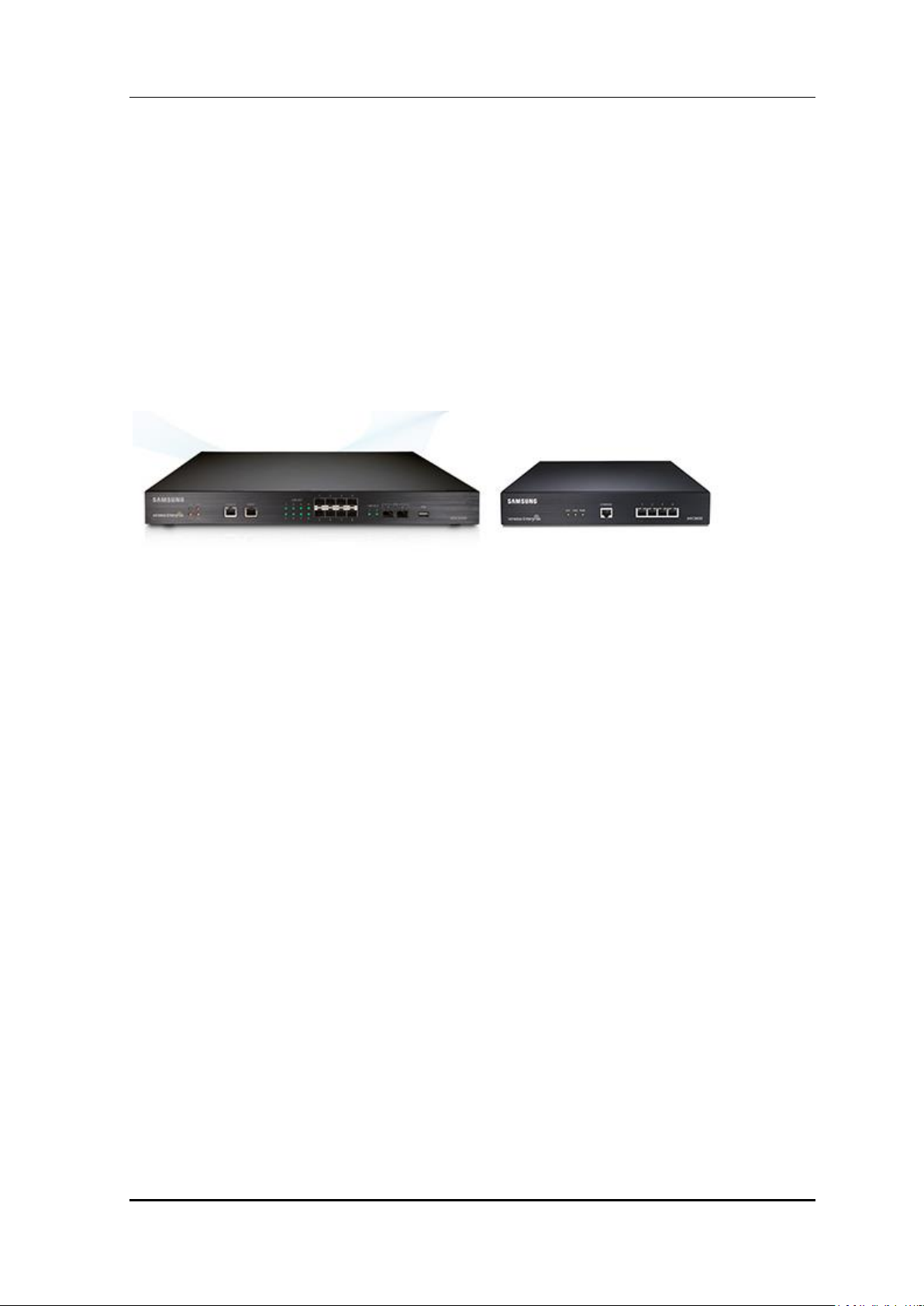
The Samsung Access Pointer Controller (APC) comprehensively manages the user
information and traffics while managing an Access Point (AP), i.e. a device that provides
wireless connection service for a user terminal in a Wi-Fi environment. There are two types
depending on the AP capacity; WEC8500 and WEC8050. It comprehensively manages all
the APs and provides services in a wireless LAN environment. Because AP and APC are
connected in tunneling, all the user traffics are exchanged and processed.
The APC is typically installed at a position where it can be connected to a backbone switch,
core switch or router in a network of enterprise environment and it controls a wireless LAN
AP and provides the functions for Wireless LAN (WLAN) services such as handover and
QoS, security/authentication, etc. The Samsung WEC8500 provides its services up to 500
APs. It can provide its services up to 10,000 connected user devices. Meanwhile, the
WEC8050 can accommodate maximum 75 APs and provides the service to maximum 1500
user devices.
The APC provides a WLAN network environment through AP management and also
provides various communication services required by enterprise customers in a wireless
environment by interoperating with other enterprise solutions. It provides Wireless
Enterprise (W-EP) solution in an enterprise environment by making the collaboration
applications such as telephone, message, or communicator, etc., that has been used in a
legacy wire environment, be able to be used in a wireless terminal such as smart phone,
tablet PC, or notebook.
Samsung Electronics America
Mobile Server
Mobile device
management, etc.
(WEC8500)
Terminal
page 19 of 533
based on Android
WEC8500/8050 Operation Manual Version 5.2
Figure 1. System Structure for Wireless Enterprise Solution
The Samsung W-EP solution, as shown in figure, comprehensively includes various
enterprise applications which are provided by wire/wireless infrastructure products and
wireless terminals. The WLAN network, a wireless infrastructure solution that provides
mobility in an enterprise environment, consists of W-EP wireless LAN Access Point (AP),
W-EP AP Controller (APC), and Wireless Enterprise WLAN Manager (WEM). (Future
Release)
The Samsung APC and W-EP wireless LAN AP are core devices that provide various
services such as user authentication, wireless management, voice and data service, etc. in
the 802.11-based Wi-Fi environment. The WEM provides convenient configuration
environment, various statistics, and event information to an operator. (Future Release)
Term
In this manual, the WEC8500/WEC8050 and APC commonly represent Samsung
AP Controller. In addition, the AP means Samsung W-EP wireless LAN AP.
Samsung Electronics America
page 20 of 533
WEC8500/8050 Operation Manual Version 5.2
W-EP AP
IP-PBX
WEC/8050WEC8500
WEM
Router
Internet
…
…
Ethernet Switch
FMC client
1.2 Network Configuration
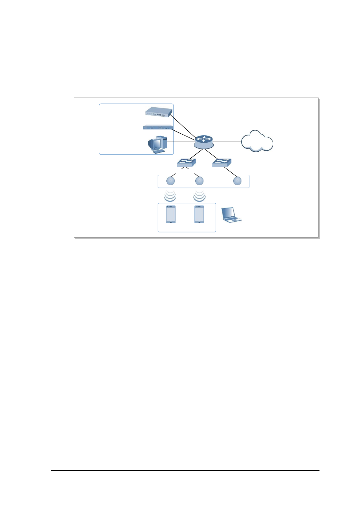
The network configuration of Samsung W-EP solution that includes APC is shown below.
Figure 2. W-EP Network Configuration
IP-PBX
As an enterprise call manager, it is a switch required to provide the Fixed Mobile
Convergence (FMC) function to a wireless terminal (optional).
APC (WEC8500/WEC8050)
The APC manages all the W-EP wireless LAN APs installed in an enterprise
communication environment and it also manages user information and traffics.
Because the W-EP wireless LAN network configuration uses a centralized structure where
all the wireless user traffics are in tunneling through the APC, the APC is one of the most
important elements related to traffic management and throughput in the W-EP environment.
An APC is typically installed at a position where it can be connected to a backbone switch,
core switch or router in a network. It controls the W-EP wireless LAN AP and provides
handover, QoS, and security/authentication functions.
WEM (Future Release)
In the W-EP wireless LAN environment, various services are provided through a complex
network configuration. As many users are involved, its management is complex and
difficult. A normal network administrator can hardly handle any problematic issue as well
as a normal management task. The WEM is a Network Management System (NMS) that
efficiently manages this kind of W-EP wireless LAN network and service environment.
It manages a WLAN network, retrieves and configures the status of APC or W-EP wireless
Samsung Electronics America
page 21 of 533

WEC8500/8050 Operation Manual Version 5.2
LAN AP.
W-EP AP (W-EP Wireless LAN AP)
The W-EP wireless LAN AP is a device that provides wireless connection service to a user
terminal. It should be installed by considering the service area or region that will be
provided in an enterprise environment. Typically, the number of W-EP wireless LAN APs
is determined by considering the size of installation area and the number of users to secure
service coverage.
Ethernet Switch
Typically, because an AP is installed in a user area, use a Power over Ethernet (PoE) switch
that does not use a power line for the beauties of environment, etc. Install the W-EP
wireless LAN APs by considering current consumption and the power capacity PoE switch.
In addition, because power drop may occur if the distance between the switch and W-EP
wireless LAN AP, the relationship between distance and power must be considered.
Typically, the distance between these two must be 100 m or less in order to avoid power
drop.
Wireless terminal/WeVoIP Client
Terminal that provides the 802.11a/b/g/n interface such as smart phone, tablet PC, or
notebook computer, etc. In an Android smart phone, an enterprise Voice over IP (VoIP)
application equipped with the Samsung voice engine is called a WeVoIP client (The
WeVoIP client is an option).
Wireless additional service
In the W-EP environment, various application services are required as well as basic
wireless connection services.
The Wireless Enterprise Security (WES) provides a security service that is one of the most
important elements in an enterprise environment. The WES can seamlessly receive wireless
connection service through the security services such as unauthorized terminal,
unauthorized AP, or ad hoc connection blocking, etc.
Location service that manages the location of a terminal in a wireless environment is also
an application service required in an enterprise environment. With this, it is possible to
manage the location of an effective user or an unauthorized user.
IP application service
The IP application servers required in an existing wire network including Dynamic Host
Configuration Protocol (DHCP) server, DNS server, web server, or RADIUS authentication
server are also used in the W-EP environment. Especially, the DHCP server and RADIUS
authentication server play a critical role in the wireless environment.
Samsung Electronics America
page 22 of 533
WEC8500/8050 Operation Manual Version 5.2
LED
Status
Description
SYS
Green
The system is operating normally
Orange
The system is now booting
Red
Preparing the system for booting
FAN (fan
module)
Green
The installed FAN module is operating normally
Orange
The system is now booting
Red
Fan module fault has occurred
PS1 (power
module 1)
Green
Normal operation of installed power module 1
Red
Power is turned off or a fault occurred while the power module 1 is
installed.
Off
Power module 1 is not installed.
PS2 (power
Green
Normal operation of installed power module 2
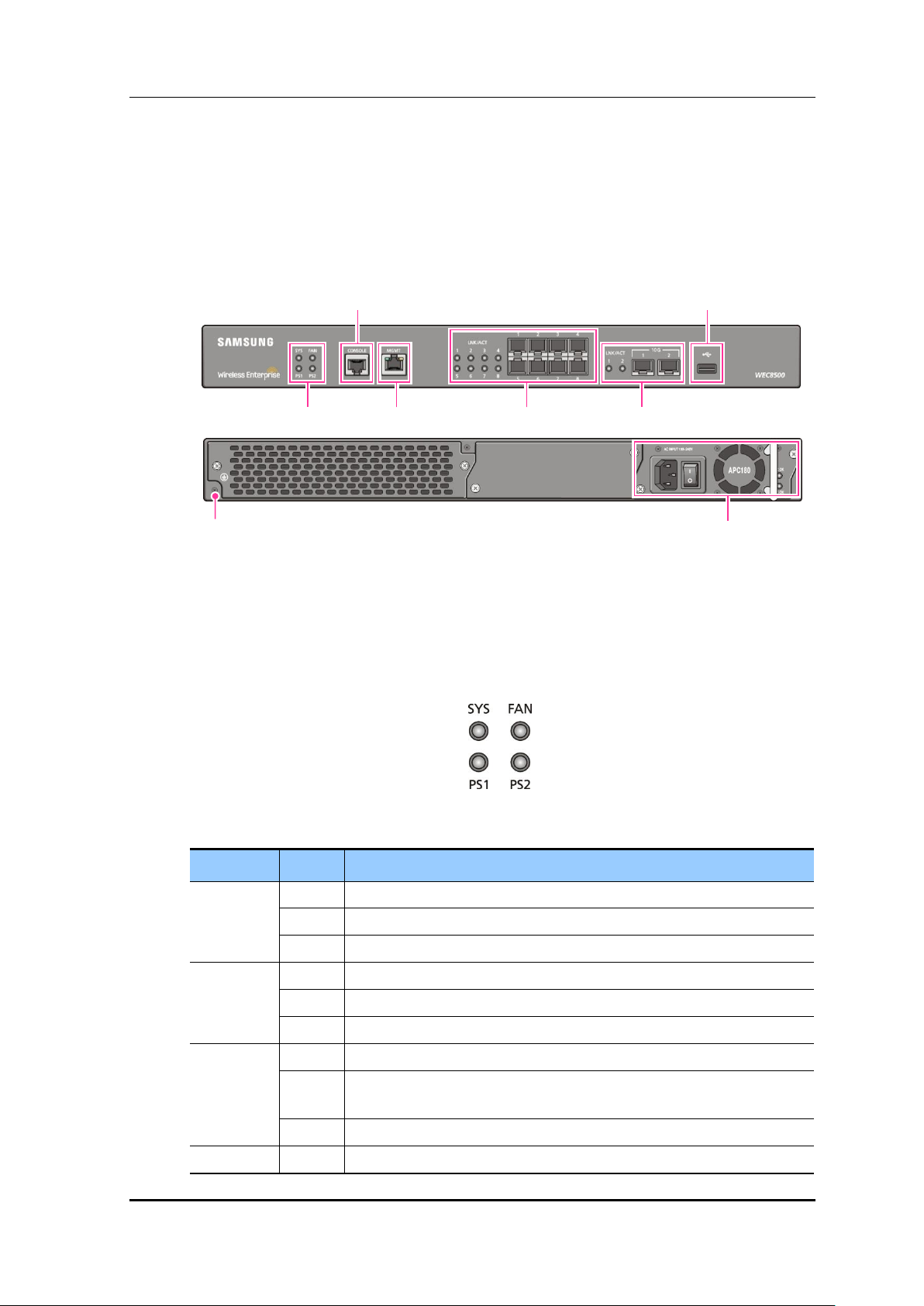
Power Module
Ground hole
System LED
Console port
Management port
1G Optic port
10G Optic port
USB port
1.3 APC Configuration and Functions
1.3.1 WEC8500 Configuration and Functions
The Configuration and the purpose of each item of WEC8500 are as follows:
Figure 3. WEC8500 Interface-Front/Back
System LED
System LED indicates the various statuses of system. Each LED displays the following
information.
Figure 4. System LED Configuration
Samsung Electronics America
page 23 of 533

WEC8500/8050 Operation Manual Version 5.2
LED
Status
Description
module 2)
Red
Power is turned off or a fault occurred while the power module 2 is
installed.
Off
Power module 2 is not installed.
Configuration item
Status
Description
LED
Green
Turned on for link connection
Orange
Blinking for data exchange
Connector
-
Connector for UTP cable connection
LED
Connector
Console port (RS232C)
A console port is used to check the operational status of WEC8500 or for input through the
CLI. Its basic requirements are as follows:
Baud rate: 115200 bps
Character size: 8 characters
Parity: None
Stop bit: 1, Data bit: 8
Flow control: None
Management port (1 GE UTP)
The WEC8500 provides a 10/100/1000BASE-T port (RJ-45) for management purpose.
It is working in 10/100 Mbps half duplex/full duplex mode or in 1000 Mbps full duplex
mode. Because it supports the automatic MDI/MDI-X function, you can use a straightthrough cable for all the network connections to a PC, server, switch, or network hub.
Figure 5. Management Port Configuration
When connecting a cable to the management port, make sure to check if the cable complies
with the 10 BASE-T, 100 BASE-TX, or 1000 BASE-T.
Cable type: UTP or STP cable using RJ-45 connector
10 BASE-T: Category 3 or higher
100 BASE-TX: Category 5 or higher
1000 BASE-T: Category 5 or higher (Category 5e or higher is recommended)
Isolate from wireless frequency disturbing waves
Shut down electrical surge
Samsung Electronics America
page 24 of 533
WEC8500/8050 Operation Manual Version 5.2
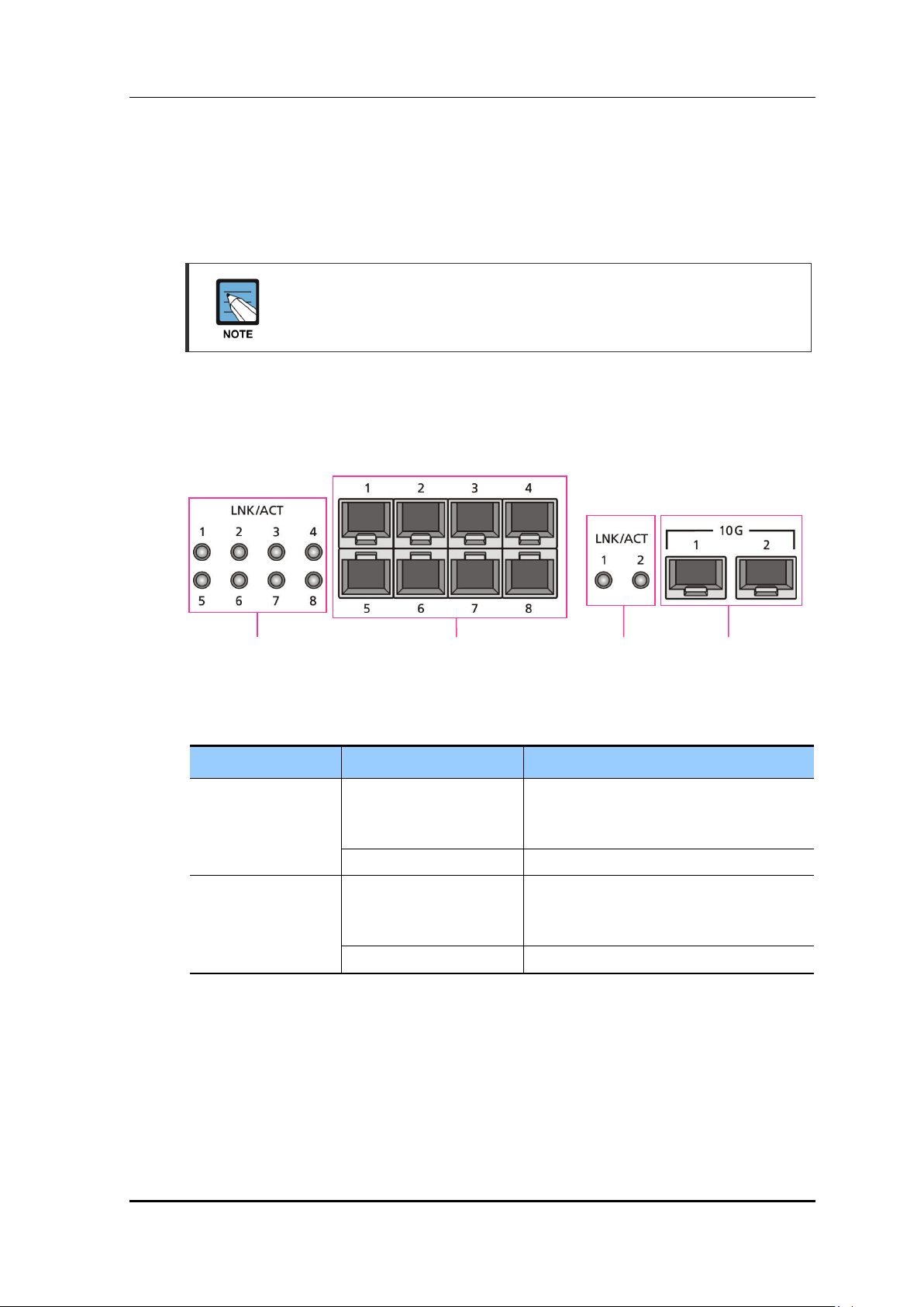
Configuration item
Port/LED
Description
10 GE ports
LINK/ACT 1, LINK/ACT 2
LINK/ACT status of each port
- Turned on for link connection
- Blinking for data exchange
10G 1, 10G 2
10 GbE Optic module connector
1 GE port
LINK/ACT 1~LINK/ACT 8
LINK/ACT status of each port
- Turned on for link connection
- Blinking for data exchange
1G 1~1G 8
1 GbE Optic module connector
1G port
LINK/ACT LED
1G port
10G port
10G port
LINK/ACT LED
Separate the electrical wiring of a switch or related devices and the electromagnetic
area of network data line
Cable or connector and safe connection without damaged cable sheath
The 1000 BASE-T standard does not support the forced mode.
The auto-negotiation function must be always used for 1000 BASE-T port or trunk
connection.
Optic port
It provides two 10 GbE Optic ports and eight 1 GbE Optic ports and the operational status
of each port is displayed in LED.
Connector
Figure 6. Optic port configuration
Connector
USB port (Host 2.0)
The WEC8500 provides a USB host port that supports the upgrade of WEC8500 operation
software.
A typical USB memory stick is supported.
Samsung Electronics America
page 25 of 533
WEC8500/8050 Operation Manual Version 5.2
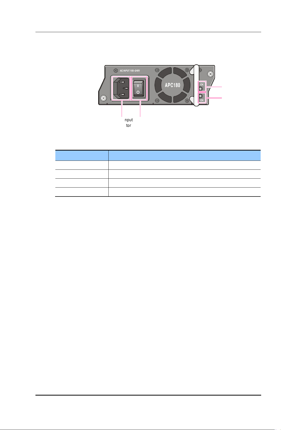
Configuration item
Description
Power input connector
Connector to connect the power cable to
Power switch
Switch to turn on/off power
AC LED
Turned on when there is a normal AC power input.
DC LED
Turned on when there is a normal DC power output.
Power input
connector
AC LED
Power
switch
DC LED
Power module
Figure 7. Power module configuration
Samsung Electronics America
page 26 of 533
WEC8500/8050 Operation Manual Version 5.2
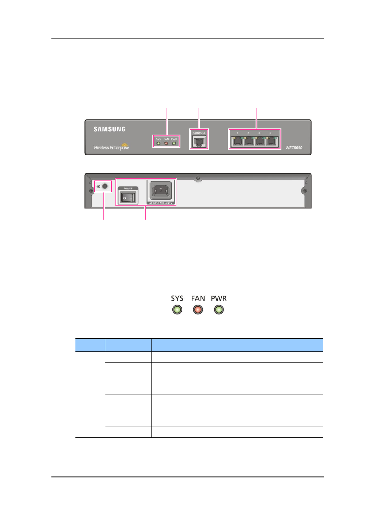
LED
Status
Description
SYS
Green
The system is operating normally
Orange
The system is now booting
Red
Preparing the system for booting
FAN
Green
The installed FAN module is operating normally
Orange
The system is now booting
Red
Fan fault
PWR
Green
The power is supplied normally
Off
The power is turned off or not supplied
Status LED
Console Port
Ethernet Port
Ground hole
Power
1.3.2 WEC8050 Configuration and Functions
The configuration and the purpose of each item of WEC8050 are as follows:
Figure 8. WEC8050 interface-Front/Back
Status LED
This LED indicates the various statuses of system. Each LED displays the following
information.
Figure 9. Status LED configuration
Samsung Electronics America
page 27 of 533
WEC8500/8050 Operation Manual Version 5.2
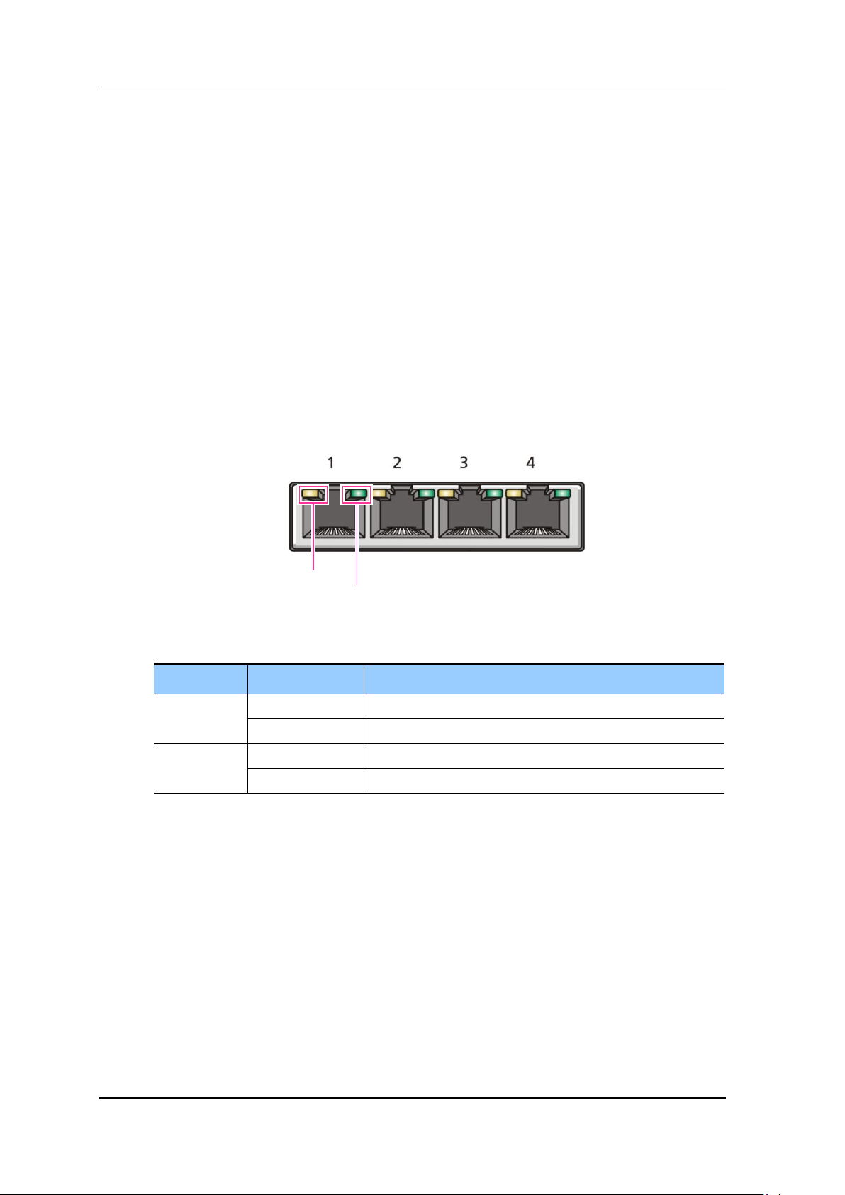
LED
Status
Description
ACT
Orange blinking
Blinking while data exchanging
Off
No data exchanging
LINK
Green
Link connection display
Off
No link connection
LINK LED
ACT LED
Console port (RS232C)
A console port is provided to check the operational status of WEC8050 or for input through
the CLI.
Its basic requirements are as follows:
Default baud rate: 115200 bps
Character size: 8 Characters
Parity: None
Stop bit: 1, Data bit: 8
Flow control: None
Ethernet port
It has 4 10/100/1000 Base-T ports.
Figure 10. Ethernet Port Configurations
Samsung Electronics America
page 28 of 533
WEC8500/8050 Operation Manual Version 5.2
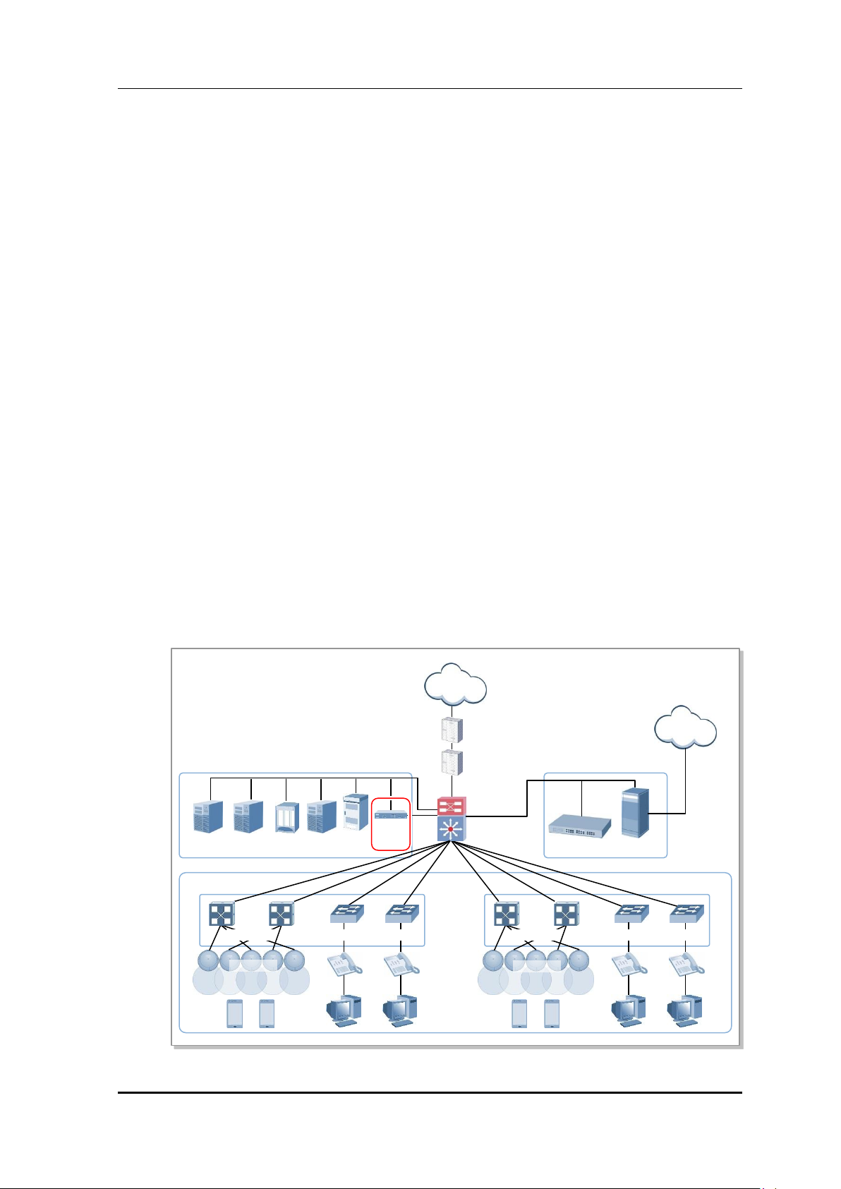
PRI
Firewall
Internet
SBC
PSTN
IP-PBX
Media G/W
APC
WES
Loc
WEM
AAA
DHCP
W-EP AP
PoE switch
Access switch
PoE switch
Access switch
W-EP AP
1.4 APC Application Configuration and Service
Scenario
1.4.1 Basic Configuration
To provide wireless connection service using a wireless LAN in the W-EP environment, the
W-EP wireless LAN AP that helps a terminal connect to the network through wireless and
an APC that controls the terminal are basically required. Especially, the role of APC is
critical to guarantee QoS of various services and provide high level of security functions in
an Enterprise communication environment. As various elements are required in the W-EP
environment, it is necessary to intuitively or organically manage each element via WEM.
(Future Release)
In addition, the IP application servers including authentication server, DHCP server, or
DNS server which is a basic network configuration element in a wire enterprise
environment are also interoperated to provide more convenient and various mobile services
to users. One outstanding example is the WeVoIP service that provides enterprise level
VoIP in a wireless LAN. With this, the wire/wireless integrated voice service can be
provided.
An example of service configuration diagram using the W-EP wireless LAN system is
shown in the below figure. The configuration diagram is based on Samsung APC
(WEC8500).
server
Samsung Electronics America
Backbone
server
Figure 11. Basic Configuration of W-EP Wireless LAN System
switch
page 29 of 533
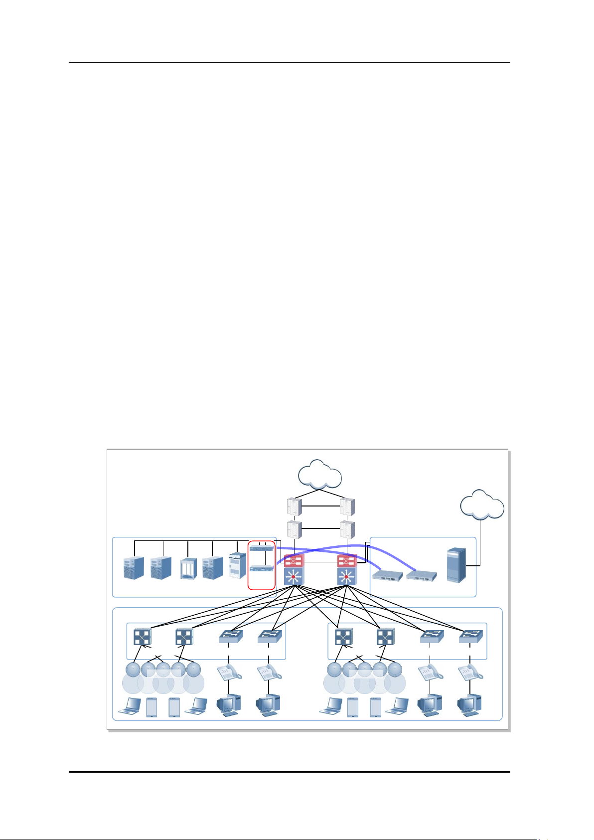
WEC8500/8050 Operation Manual Version 5.2
PRI
Firewall
Internet
Backbone
SBC
PSTN
IP-PBX
Media G/W
APC
WES
Loc
WEM
AAA
DHCP
PoE switch
Access switch
PoE switch
Access switch
IP-PBX
W-EP AP
W-EP AP
The basic W-EP wireless LAN network configuration is a centralized structure where all
the wireless user traffics go through tunneling between APC and W-EP wireless LAN AP.
Therefore, the network information such as subnet information allocated to a wireless user
depends on the configuration of backbone network where the APC is connected.
This provides the following advantages during network configuration and setup.
Installing the APC is just adding it to a legacy data center or backbone network.
Therefore, the possibility of physical change of core network can be reduced.
In addition, separate design of wire/wireless network is easy using the APC as a
boundary.
No dramatic network change is required to install the W-EP wireless LAN AP.
An AP installed in a user area is located in various local network environments in a
wide region. Although it is unavoidable to install or expand a PoE switch, the
modification of local network where wire users are already configured can be
minimized.
Because the APC relays all the user traffics, it can restrict a wireless attacker’s effects
and provide differentiated service for each user.
1.4.2 Configuration of Multiple APC for Redundancy
The APC provides the redundancy function to guarantee QoS for various services and
provide service stability in the W-EP environment.
An example of service configuration diagram for redundancy is shown in the below figure.
switch
server
server
Figure 12. Example of W-EP Wireless LAN System Configuration for Redundancy
Samsung Electronics America
page 30 of 533
 Loading...