

WEA554i/d Quick User Guide
This guide describes the overview, names and features, and important
test items of Wireless Enterprise WEA554i/d before installation.
Overview
WEA554i/d Overview
The WEA554i/d is an outdoor Wireless Enterprise AP that supports IEEE
802.11ac wave2 specifications.
It connects UE that supports wireless LAN, such as smartphones, tablets
or laptops to a wired network in an outdoor environment.
The WEA554i/d supports the following features.
- IEEE 802.11a/b/g/n/ac wave2 standards and Security/QoS specifications
- IEEE 802.3af/802.3at standards PoE (Power over Ethernet)
- 4 × 4 MU-MIMO with 4 spatial streams
- Wireless LAN through both 2.4-GHz and 5-GHz bandwidths
- A LED indicating the operational status of WEA554i/d.
- Operating temperature: -40 to +65°C (without solar loading)
- Resistance to dust/water: IP66 & IP67
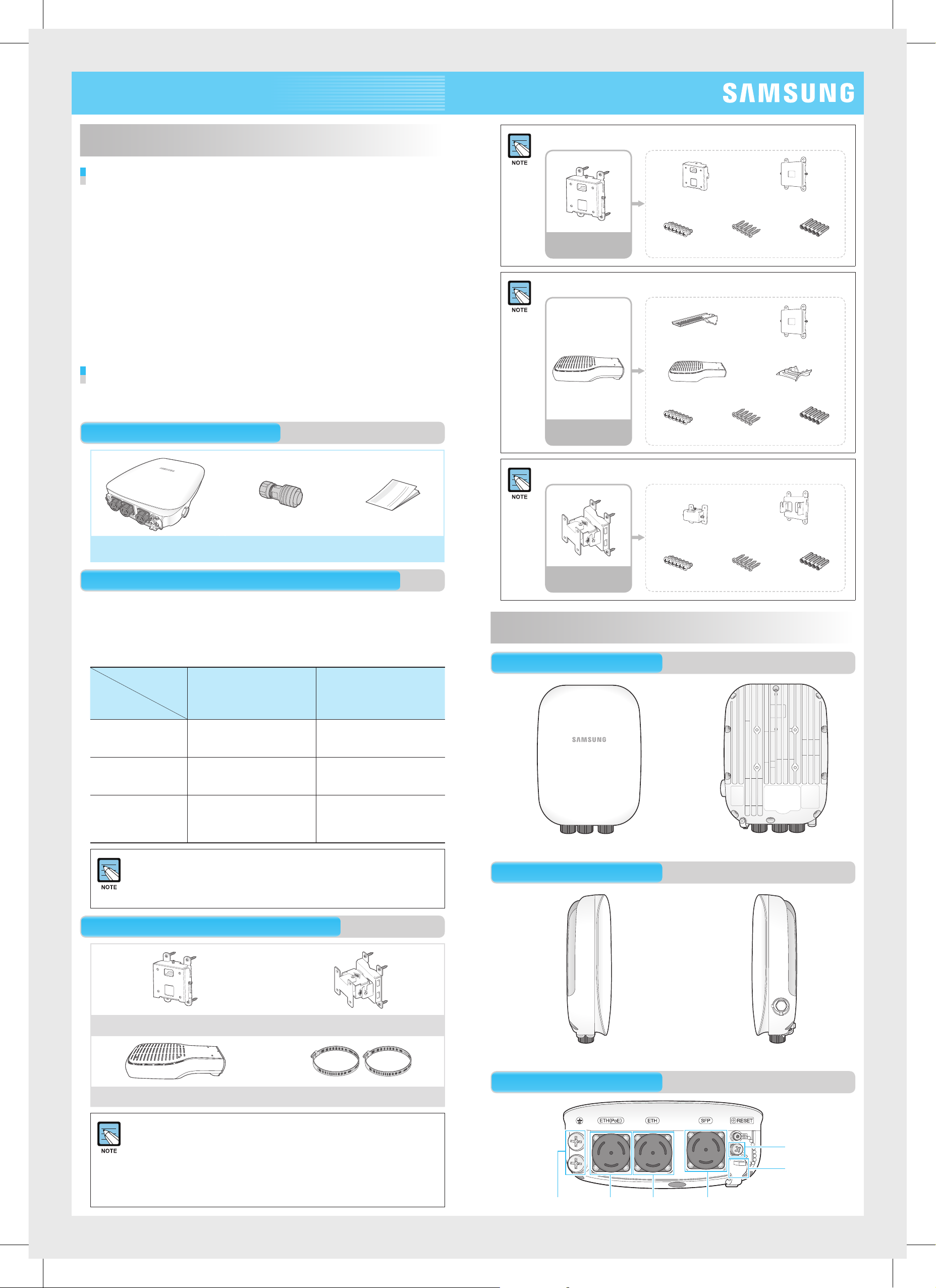
Components
After unpacking the packaging of WEA554i/d, confirm that all of the
package contents below are included.
Package Contents
The vertical installation kit consists of five sub-units.
Vertical unit bracket Vertical mounting bracket
Vertical
installation kit
The horizontal installation kit consists of seven sub-units.
Horizontal
Installation Kit
M5 × L14 screws M4 × L25 screws Plastic anchor
Horizontal unit bracket
Vertical mounting bracket
Bracket cover Top Bracket cover bottom
M5 × L14 screws M4 × L25 screws Plastic anchor
WEA554i/d AP
Waterproof Connector
for Ethernet cable
Quick User Guide
Additional Components for Each Type of Installation
WEA554i/d supports six types of installation as described in the table below.
The types of installation differ depending on the installation method (Vertical/
Tilt/Horizontal) and the mounting position (wall/pole).
The additional components (kit) required for each type of installation must
be purchased separately.
Mounting
Position
Installation
Method
Vertical Installation Type 1: Vertical_Wall
Installation (Vertical installation
kit 1 pc.)
Wall Pole
Type 2: Vertical_Pole
Installation (Vertical installation
kit 1 pc., metal band 2 pc.)
The tilt installation kit consists of five sub-units.
Tilt Installation
Kit
M5 × L14 screws M4 × L25 screws Plastic anchor
Name and Function
Front/Back
Tilt unit bracket Tilt mounting bracket
Tilt Installation Type 3: Tilt_Wall Installation
(Tilt installation kit 1 pc.)
Horizontal Installation Type 5: Horizontal_Wall
Installation (Horizontal
installation kit 1 pc.)
If installing the WEA554i/d on a wall, purchase an additional components
kit depending on the type of installation (vertical/tilt/horizontal).
However, when installing the WEA554i/d on a pole, purchase the
additional components kit with two metal bands.
Additional Components (Sold Separately)
Vertical Installation Kit
Type 4: Tilt_Pole Installation
(Tilt installation kit 1 pc., metal
band 2 pc.)
Type 6: Horizontal_Pole
Installation (Horizontal
installation kit 1 pc., metal
band 2 pc.)
Tilt Installation Kit
[Front] [Back]
Side (Left/Right)
[Left] [Right]
Horizontal Installation Kit Metal Band (2 pc.)
For additional components, single units, which are not assembled
as a kit, are packaged and sold in bulk. After purchase, you should
therefore assemble and use the units in the form of a combination or
kit suitable for installation by referring to the ‘WEA554i/d Installation
Manual’ on the website below.
- http://www.samsungdocs.com
- http://v3.samsunggsbn.com/b2t
Base
Factory reset
switch
Status LED
Ethernet port (PoE)Ground terminal Ethernet port Optical port
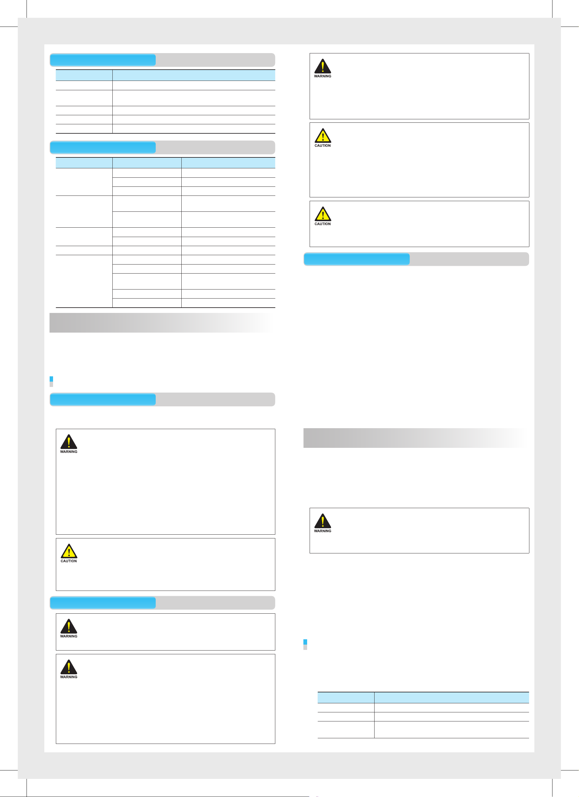
Interface
Ground Cable Connection
Interface Description
Status LED Indicates the operating status of WEA554i/d.
Ethernet port (PoE) Supports 1000 BASE-T Gigabit Ethernet and PoE IEEE
802.3af/802.3at.
Ethernet port Supports 1000 BASE-T Gigabit Ethernet.
Optical (SFP) port Supports 1000 BASE-X Gigabit Ethernet.
Factory reset switch Used to reset WEA554i/d to its default factory settings.
Status LED
Operation Mode LED Status Description
System start White Initial LED status
Blue Device reset and diagnostic test
Red Boot failure (device reset failure)
Provisioning Repeating red and green Connecting APC (network link:
normal)
Blinking green Connecting CAPWAP link (APC
server connection: normal)
Normal operation Green Wireless UE not connected
Blue Wireless UE connected
Upgrade Blinking blue Upgrading software
Failure Blinking red Network connection failure
Blinking yellow IP address conflict
Blinking purple Dynamic IP address allocation
failure
Blinking bluish green Network connection failure
Repeating red and blue Wireless interface failure
Installation
Please check if all components are included before installation.
The WEA554i/d can be installed on a pole or wall according to its installation
environment, and can be installed vertically or horizontally depending on its
installation purpose. When installing vertically, make sure that the I/O ports are
facing downwards.
Before Installation
Safety Recommendations
Carefully observe the following safety warnings in order to avoid the risk of damage
or injury. For safe use, make sure to be well-informed.
When connecting the cables, always connect the ground
cable first. Contacting the system, connecting the cables or
maintaining the system without the connection of the ground
cable may damage the system due to static electricity and
short-circuit. This may also lead to injuries to the operator.
Measuring the Insulation Resistance
When measuring the insulation resistance, high voltage is used.
Therefore, please follow the precautions below in order to prevent any personal
injuries or damage to the system.
- Disconnect all cables that are connected to the system before measuring the
insulation resistance.
- Do not measure the insulation resistance when the power is on.
- Do not measure the insulation resistance of the internal system units and the
components other than the intended area.
Grounding the System
The MGBs for the lightning arrester, power or communication must be separated.
These three types of MGBs can be grounded by the isolation grounding system
or the common grounding system that is branched off at the mesh installed
underground.
Installation Instructions
Follow the instructions below carefully during installation.
- The location of the system must be easily accessible for installation, cable
connection or maintenance purposes.
- The PoE LAN cable must always be installed away from any sources of electrical
interference, such as a power lines, fluorescent lights, radios or transmitters.
- For PoE LAN cable, use SFTP (Shielded Foiled Twisted Pair) cable of CAT.6 or
above with Φ 8.1-8.5.
- If PoE switch is unable to use, a PoE injector that satisfies IEEE 802.3af/at power
specifications may be used.
- When installing the WEA554i/d more than 100 m away from the APC, it is
recommended to use SFP (small form pluggable) optical modules that fulfill
1000 BASE-X specifications. To avoid any compatibility issues, use SFP optical
modules from the same manufacturer with the same specifications. In addition,
PoE injectors and SFP optical modules must fulfill the operating temperature of
the WEA554i/d APs.
- The 3-pin (including ground) power plug that supplies 100-240 V AC, 50-60 Hz
must be within 2 m of each device, and the power must be supplied through an
independent circuit breaker.
- It is recommended to use an equipment that uses a filter or a surge breaker.
- There is a risk of electrical shock.
Make sure that the power is turned off during installation.
Do not proceed with the installation if there is any electrical
current leaking. It may cause a serious electric shock.
- Wear anti-static gloves or take an appropriate action to
prevent ESD when handling the product.
- Do not connect a phone line to an Ethernet port.
This may damage the product.
- This product must be connected to a power supply in
compliance with IEEE 802.3af/at or connected to a limited
power supply in compliance with IEC/EN/UL 60950-1.
- This product must be installed or removed by appropriately trained service
personnel only.
- Install WEA554i/d outdoor, since it is for outdoor use.
For further details, refer to Environment A of IEEE 802.3af standard.
- During installation, this product must be installed at least 3 m or more apart
from WiMAX/3G/4G repeater or antenna.
Safety Signs
Do not wear metal accessories
Be careful not to short-circuit the power line with metal
accessories that you may be wearing, such as a watch or ring.
Grounding
Grounding is the process of operating an electronic system (for example, power
supplying system, communication system, and control system) stably from a
lightning, transient-current, transient-voltage, and electric noise and of preventing
injury from electric shock.
Ground equipment minimizes the electrical potential of the electronic device to that
of the ground, which is zero electrical potential, so that it can prevent the device
from occurring electrification.
Connect the ground cable first. In cabling, the connection
of cables without the connection to the ground cable
may cause damage of the equipment or bodily injury to
personnel.
The purposes of the ground construction are as follows:
- To prevent human life and the system from over-current, over-voltage, and
lightning.
- To provide a discharge path for surge voltage generated by lightning and power
switch.
- To protect the system from static electricity.
- To eliminate or minimize the high-frequency potential in the system housing.
- To provide a conductor for the balance and stability of high-frequency current.
- To stabilize the potential of the circuit against the ground.
Connecting Ground Cable
Be careful when using a Megger tester
When using an insulation resistance tester, keep in mind the
following safety precautions to prevent an electric shock:
- Connect the Earth COM (black) and AC.V (red) lead wires
to the correct polarities. At this point, make sure that you
do not touch the connected probe (the reading part of the
lead wire) with your hand or any other body parts.
- Never touch the system with any part of your body while
measuring the insulation resistance.
To connect the ground cable, do the following:
Make sure you have the following items:
1.
- Parts and Tools for connecting Ground Cable
Category Description
Installation Section MGB~Outdoor AP Ground Terminal
Cable 4 mm2 × 1C
Heat Shrink Tube
(Spec/Color/Length)
0.39 in. (10 mm)/Green/1.96 in. (50 mm)
Ф
 Loading...