

Samsung WEA504I Users Manual
This manual describes the configuration of the Wireless Enterprise WEA400/500 series and
its installation procedures.
WEA400/500 Series (Indoor) Quick Installation Manual
The installation procedures are described based on the WEA403i/412i/413i/403Si/504i/514i configurations.
The same installation procedures apply to the WEA403e model, except for the antenna installation.
Introduction
What is the WEA400/500 series?
The WEA400/500 is a series of APs fromthe Samsung WE wireless LAN family.
They connect a UE such as a smart phone, a tablet PC or a laptop that supports the
wireless LAN to a wired network. The WEA400/500 series supports the following features:
- IEEE 802.11a/b/g/n/ac standard
- PoE (Power over Ethernet) IEEE 802.3af/802.3at
- WEA412i: 2 × 2 MIMO (Multiple Input Multiple Output)
- WEA403i/403e/413i: 3 × 3 MIMO (Multiple Input Multiple Output)
- WEA504i/514i: 4 × 4 MU-MIMO (Multi User-Multiple Input Multiple Output)
- Wireless LAN through both 2.4 GHz and 5 GHz bandwidth simultaneously
- WEA403Si supports the connection of various sensors and equipment to a network with
WLAN, BLE, ZigBee.
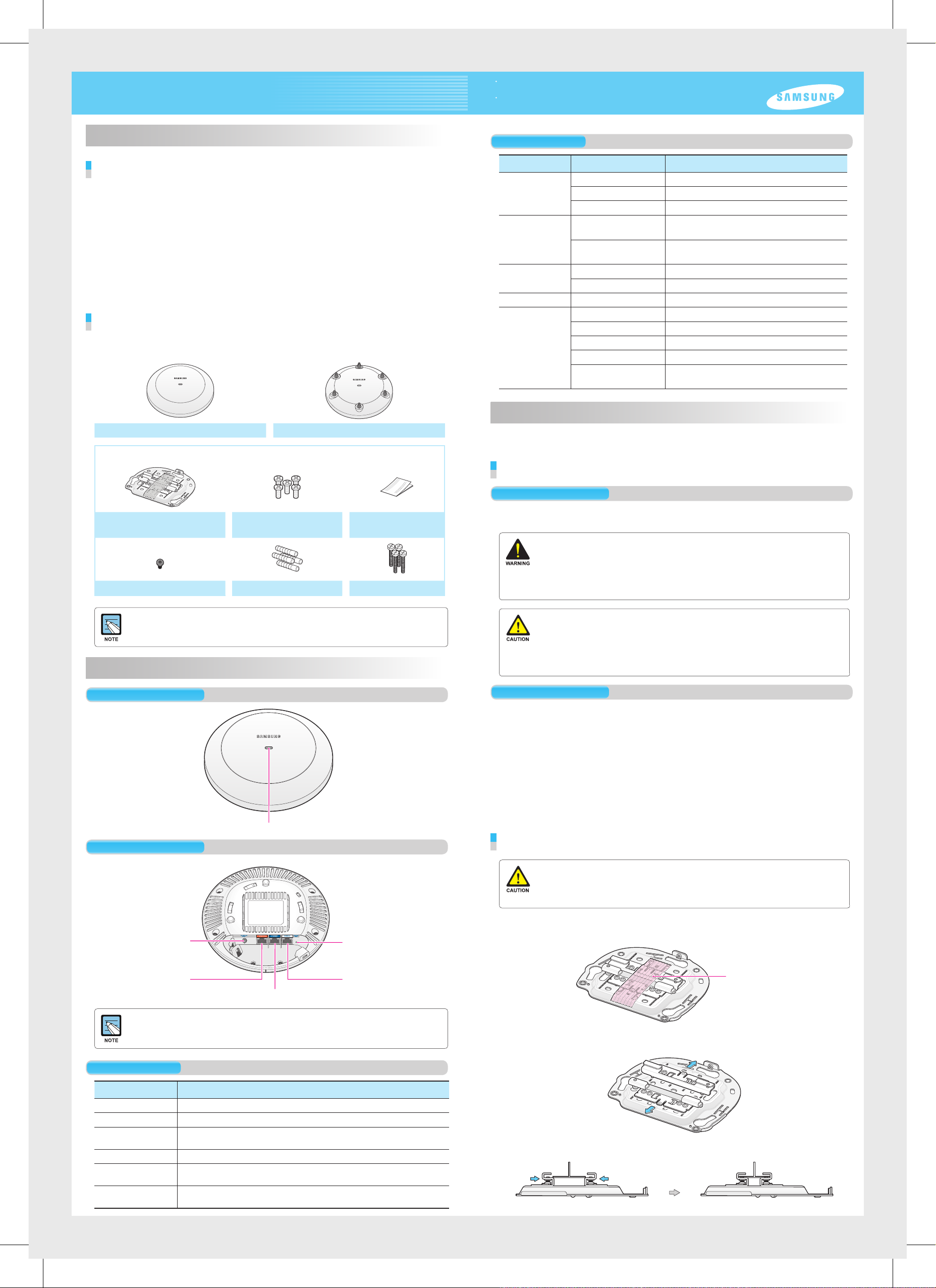
Components
After unpacking the WEA400/500 series, check whether all of the following components
are included.
WEA403i/412i/413i/403Si/504i/514i WEA403e
Common merchandise
Status LED
LED Status Description
System start
status
Provisioning
Status
Normal
operation status
Upgrade Green blinking Software upgrade in progress
Error status Red blinking Physical connection error of network
White On Initial LED status
Blue On Device reset and test in progress
Red On Booting failure (Device reset failure)
Red, green and off
repeated
Green blinking CAPWAP connection in progress
Green On When there is no connected wireless UE
Blue On When there is a connected wireless UE
Yellow blinking IP address conflict
Purple blinking Dynamic IP address allocation failure
Bluish-green blinking Logical connection error of network
Red, green and off
repeated
APC connection in progress
(Network link normal)
(APC server connection normal)
Wireless interface error
Installation
The WEA400/500 series can be installed on ceilings or walls.
Please check whether all the components are included before installation.
Before Installation
Mounting Bracket
5 M3 × L6 screws
(Including 1 spare)
Installation Manual
Security Torx (T10) Screw Plastic 4 anchors M4 × L28 4 screws
- It is recommended to keep all packaging materials and the box.
- The power adapter and the external antenna for WEA403e are sold separately.
When necessary, please contact the place of purchase.
Names and Functions
Front View
Status LED
Rear View
Safety Requirements
Risks may be caused when the following safety warnings are not properly observed.
For safe use, make sure to be well-informed.
- There is an electrical risk with the product. Make sure that the power is off during installation
and do not proceed with the installation when there is current leakage. Use of products with
current leakage may cause serious electrical shock to the user.
- Wear anti-static gloves or take appropriate actions to prevent ESD when handling the product.
- This product must be connected to ta power supply in compliance with IEEE 802.3af/at or to a
limited power supply in compliance with IEC/EN/UL 60950-1.
- This product must be installed or removed only by appropriately-trained service personnel.
- This product operates with SELV (Safety Extra Low Voltage) according to IEC/EN/UL 60950-1.
- All interconnecting equipment including this product must be installed within the same
building. For details, refer to Environment A of IEEE 802.3af/at standard.
- This product must be installed with at least 3 m or more distance from the WiMAX/3G/4G
repeater or antenna.
Installation Instructions
The instructions below must be followed when installing.
- It must be installed in a place that can be easily accessed for product installation, cable
connection and maintenance.
- The PoE LAN cable must be always installed away from any electrical interference
source such as power lines, fluorescent lights or transmitters.
- The PoE LAN cable must be CAT 5E or higher.
- When PoE is unavailable, a power adapter (sold separately) can be used. The 3-pin
(including ground) power socket that supplies 100~240 V AC, 50~60 Hz must be
located within 2 m from each equipment and the power must be supplied through an
independent circuit breaker. It is recommended to use the equipment that uses a filter
or a surge.
Installation on Ceilings (When the ceiling type is T-bar)
DC Input
Ethernet Port (PoE)
Ethernet Port
Dust covers are installed on power ports (DC 48 V/0.75 A), Ethernet ports and console ports
(CONSOLE). Remove the covers before use.
Factory Reset Switch
Console Port
Interface
Port Name Description
Status LED Displays the status information of the WEA400/500 Series via LED.
DC Input Used when a power adapter is used for power supply.
Ethernet Port (PoE) Supports 1000 BASE-T Gigabit Ethernet and PoE IEEE
802.3af/802.3at.
Ethernet Port Supports 1000 BASE-T Gigabit Ethernet.
Console Port Used for checking the operational status of the WEA400/500 series
and for CLI input.
Factory Reset
Switch
Used for initialization when commencing factory shipment of the
WEA400/500 series.
- When incorrectly installed on the ceiling, the WEA400/500 series may drop onto a person or
equipment. Therefore, make sure to fix it firmly.
- If the ceiling type is not T-Bar, please refer to the ‘Installation Manual’ provided separately.
For this installation manual, please contact the dealer.
Remove the holding tape that was attached to fix the ceiling clip.
1.
Holding tape
Open the ceiling clip so that it is wider than the width of the T-bar.
2.
Move the ceiling clip so that it is appropriate for the T-bar width.
3.
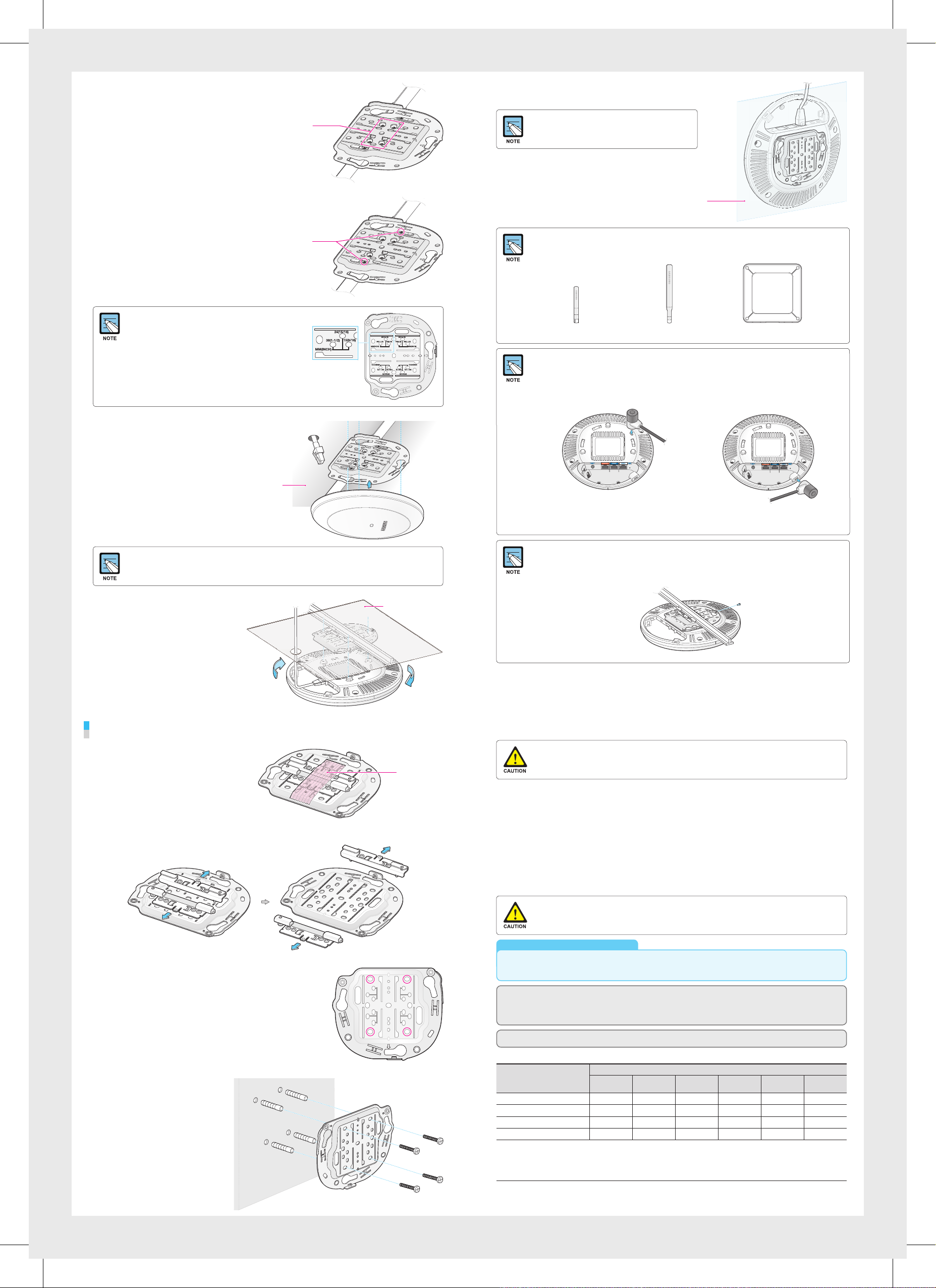
Fix the ceiling clip in place by
4.
tightening the 4 designated screws.
Insert a LAN cable into the Ethernet port (PoE) on
5.
the back side of the WEA400/500 series.
Fix the T-bar in place by fastening
5.
the screws (total of 2) that are on
the ceiling clip.
If the T-bar size of the ceiling is 15 mm, 24 mm or
38 mm, the position to fix the ceiling clip can be
checked from the bottom surface of the mount
bracket. If the T-bar size is unknown, push the
ceiling clip to check the fixing positions.
Screws for fixing
the ceiling clip
Screws for
fixing T-bar
If PoE is not supported, connect the power
adapter to the DC input on the back of the
WEA400/500 series.
The wall
For the WEA403e model, remove the protection cap from the antenna connector and install the
external antenna (separately purchased). The 3 types of antennas that can be installed to the
WEA403e model are listed below. (More antenna types may be added in the future.)
Low gain dipole antenna Patch antennaHigh gain dipole antenna
Installing Anti-Theft Lock Cable
When installing the WEA400/500 series AP in a public place, it is recommended to use antitheft lock cables to prevent any loss. (An anti-theft lock cable can be purchased separately and
a variety of products can be found in the market.)
1.
Connect the anti-theft lock cable to the WEA400/500 series AP.
Pull out a LAN cable through a hole on
6.
the ceiling and connect is to an Ethernet
port (PoE) on the back side of the
WEA400/500 series.
Exterior of the ceiling
If PoE is not supported, connect the power adapter to the DC input on the back side of the
WEA400/500 series. The output of the power adapter is 48 V/0.75 A and is not compatible with
the 12 V/2 A output power adapter that is used by the previous WEA302i/303i/303e AP.
Align the WEA400/500 series with
7.
the 3 holes on the mount bracket
and then turn clockwise to fix it
in place. Clean up the ceiling and
other cables.
Installation on Walls
Interior of the ceiling
or
2.
Turn the lock cable key to lock the cable.
3.
Remove the key from the lock cable and keep it in a separate location.
Using the anti-theft Torx screws
The WEA400/500 series AP products can be prevented from being stolen when tightening the
Torx screws as shown below. (Torx screws can be easily tightening when they are fixed to the
mount bracket before assembling the AP product.)
This eq uipmen t has been tested and f ound to com ply with th e limits for a Class B d igital d evice, pu rsuant to p art 15 of the FCC Rules.
These l imits are d esign ed to provid e reasonable pro tection against harmful i nterfe rence in a re siden tial inst allati on. This equipme nt gener ates,
uses an d can radi ate radio frequen cy energ y and, if not i nstall ed and use d in accor dance wi th the inst ructio ns, may cau se harmf ul inter ferenc e
to radio co mmunic ations. H owever, there i s no guara ntee that interference will not occu r in a part icular i nstall ation. If th is equip ment doe s
cause ha rmful i nterfe rence to radio or tele vision r eceptio n, which c an be determined by t urning t he equip ment of f and on, the u ser is
encou raged to tr y to corre ct the inte rference by one or m ore of the fo llowing m easure s:
- Reori ent or rel ocate the re ceivi ng antenn a.
- Increa se the sep aration betwee n the equi pment an d receiv er.
- Conne ct the equ ipment i nto an outle t on a circuit different fro m that to whic h the rece iver is co nnecte d.
- Consult the dea ler or an ex perie nced rad io/T V techni cian for h elp.
Remove the holding tape that was
1.
attached to fix the ceiling clip.
Remove the ceiling clip from the mount bracket.
2.
Place the mount bracket on the wall.
3.
Mark and drill 4 screws in appropriate spots.
Holding tape
Changes or modifications not expressly approved by the party responsible for compliance
could void the user’s authority to operate the equipment.
The 5150-5250 MHz ba nd is rest ricted to in door use o nly.
This device com plies wi th Indus try Canada lice nce-exe mpt RSS sta ndard(s). O peratio n is subje ct to the following t wo condit ions: (1) this
device m ay not caus e interference, and (2) this de vicemu st accept any inter ference, inclu ding inte rfere nce that may cause un desire d
operation of thedevice.
Le prése nt appar eil est co nforme a ux CNR d’Ind ustrie C anada ap plicables aux a pparei ls radio exe mpts de li cence.
L’exploitat ion est au torisé e aux deux c onditi ons suiv antes: (1) l’apparei l ne doit pa s produi re de broui llage, et (2) l’ut ilisate ur de l'appa reil doi t
accepte r tout brou illage r adioél ectriq ue subi, m ême si le br ouillage est sus ceptibl e d’en compro mettre le fonctio nnement.
FCC RF Ra diat ion Ex posur e Stat emen t:
This eq uipmen t compli es with FC C RF radiat ion expos ure limi ts set for th for an unc ontroll ed environment.
This eq uipmen t should b e instal led and op erated wi th a minim um dista nce of 50 cm be tween th e radiato r and your bo dy.
This tra nsmit ter must not b e co-located or op erating i n conjun ction wi th any other antenna o r transmi tter.
RSS-102 RF Exposure
L’antenne (ou le s antennes) doi t être insta llée de façon à ma intenir à tout inst ant une distan ce minimum de au moins 50 cm ntre la s ource de radiati on
(l’antenne) et toute per sonne physique. C et appareil ne do it pas être instal lé ou utilisé en conjonc tion avec u ne autre an tenne ou émetteur.
Should the access point be installed in a ceiling with ventilation, the AP ETHERNET PORT must
be horizontally placed.
Electromagnetic Wave Suitability Notice
Class B Equipment (For Home Use Broadcasting & Communication Equipment)
This eq uipme nt is home use (Clas s B) electromagnetic wave suitabi lity equipme nt and to be used mainly at home and it can
be used in all areas.
Regulatory Information
‘Hereby, Samsung Electronics, declares that this WEA400/500 is in compliance with the essential requirements and other relevant
provisions of Directive 1999/5/EC.’
The original Declaration of Conformity may be found at http://www.samsungdocs.com, go to Search Product and enter the model name.
AEEE Yön etme liğin e Uygund ur (Comp liant with WEE E)
Use a hammer to insert
4.
4 plastic anchors into the
drilled holes on the wall.
Align the inserted plastic
anchors and the screw
holes of the bracket.
Fix the bracket to the wall
by fastening four M4 × L28
screws.
产品中有害物 质的名称及含 量
部件名称
金屬 料件 × ○ ○ ○ ○ ○
印刷电路板部件 × ○ ○ ○ ○ ○
線材 × ○ ○ ○ ○ ○
塑膠件 ○ ○ ○ ○ ○ ○
本表格依据SJ/T11364的规定编制
○: 表示该有害物质在该部件所有均质材料中的含量均在GB/T26 572规定的限量要求以下。
×: 表示该有害物质至少在该部件的某一均质材料中的含量超出GB/T26 572规定的限量要求。本表格提供的信息是基于供应商提供的数
据及三星公司的检测结果。在当前技术水平下、所有有毒有害物质或元素的使用控 制到了最底线。三星公司会继续努力通过改善技术
来减少这些物质和元素的使用。
铅
(Pb)
汞
(Hg)
镉
(Cd)
有害物質
六价铬
(Cr
多溴联 苯
6+
)
(PB B)
http://www.samsungenterprise.com
多溴二 苯醚
(PBDE)
Part No.: EC00-00000A (Ver.1.0)
IC Information to User
“This device complies with Industry Canada licence-exempt RSS standard(s). Operation is subject to the following two
conditions: (1) this device may not cause interference, and (2) this device must accept any interference, including
interference that may cause undesired operation of the device.”
Cet appareil est conforme avec Industrie Canada RSS standard exempts de licence(s), Son utilisation est soumise à Les deux
conditions suivantes: (1) cet appareil ne peut pas provoquer d’interférences et (2) cet appareil doit accepter Toute
interférence, y compris les interférences qui peuvent causer un mauvais fonctionnement du dispositif.
 Loading...