

Samsung WEA453e AP Installation Manual
WEA453e Installation Manual Version 1.0
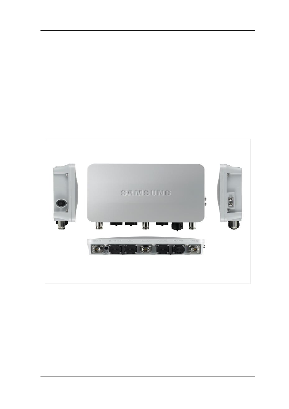
WEA453e AP
Installation Manual
Samsung Electronics America Page 1 of
117

WEA453e Installation Manual Version 1.0
Disclaimer
Every effort has been made to eliminate errors and ambiguities in the information contained in this
document. Any questions concerning information presented here should be directed to SAMSUNG
ELECTRONICS AMERICA, 1301 E. Lookout Dr., Richardson, TX. 75082 telephone (972)889-6700.
SAMSUNG ELECTRONICS AMERICA disclaims all liabilities for damages arising from the
erroneous interpretation or use of information presented in this manual.
Publication Information
SAMSUNG ELECTRONICS AMERICA reserves the right without prior notice to revise information
in this publication for any reason. SAMSUNG ELECTRONICS AMERICA also reserves the right
without prior notice to make changes in design or components of equipment as engineering and
manufacturing may warrant.
Copyright 2015
Samsung Electronics America
All rights reserved. No part of this manual may be reproduced in any form or by any means-
graphic, electronic or mechanical, including recording, taping, photocopying or information retrieval
systems – without express written permission of the publisher of this material.
Trademarks
Product names mentioned in this manual may be trademarks and/or registered trademarks of their respective
companies.
Samsung Electronics America Page 2 of
117

WEA453e Installation Manual Version 1.0
INTRODUCTION
Purpose
This manual covers how to connect and install the Wireless Enterprise Outdoor AP.
Document Content and Organization
This manual consists of 4 Chapters, 3 Annexes, and Abbreviation as follows.
CHAPTER 1. Preparation
Describes safety guidelines for installing and configuring the Outdoor AP.
CHAPTER 2. System Installation
Describes the installation procedure for the Outdoor AP.
CHAPTER 3. Cables Connect
Describes the connection procedure of cables to the installed Outdoor AP.
CHAPTER 4. Inspecting the Installation Status
Describes the procedure for checking the installation status of the system after installation
when the cables have been connected.
ANNEX A. Connector Assembly
This annex describes the process for Connector Assembly.
ANNEX B. Pressure Terminal Assembly
This annex describes the process for Pressure Terminal Assembly.
ANNEX C. Standard Torque
This annex describes the for Standard Torque.
ABBREVIATIONS
This chapter provides definitions for the abbreviations used in this manual.
Samsung Electronics America Page 3 of
117
WEA453e Installation Manual Version 1.0
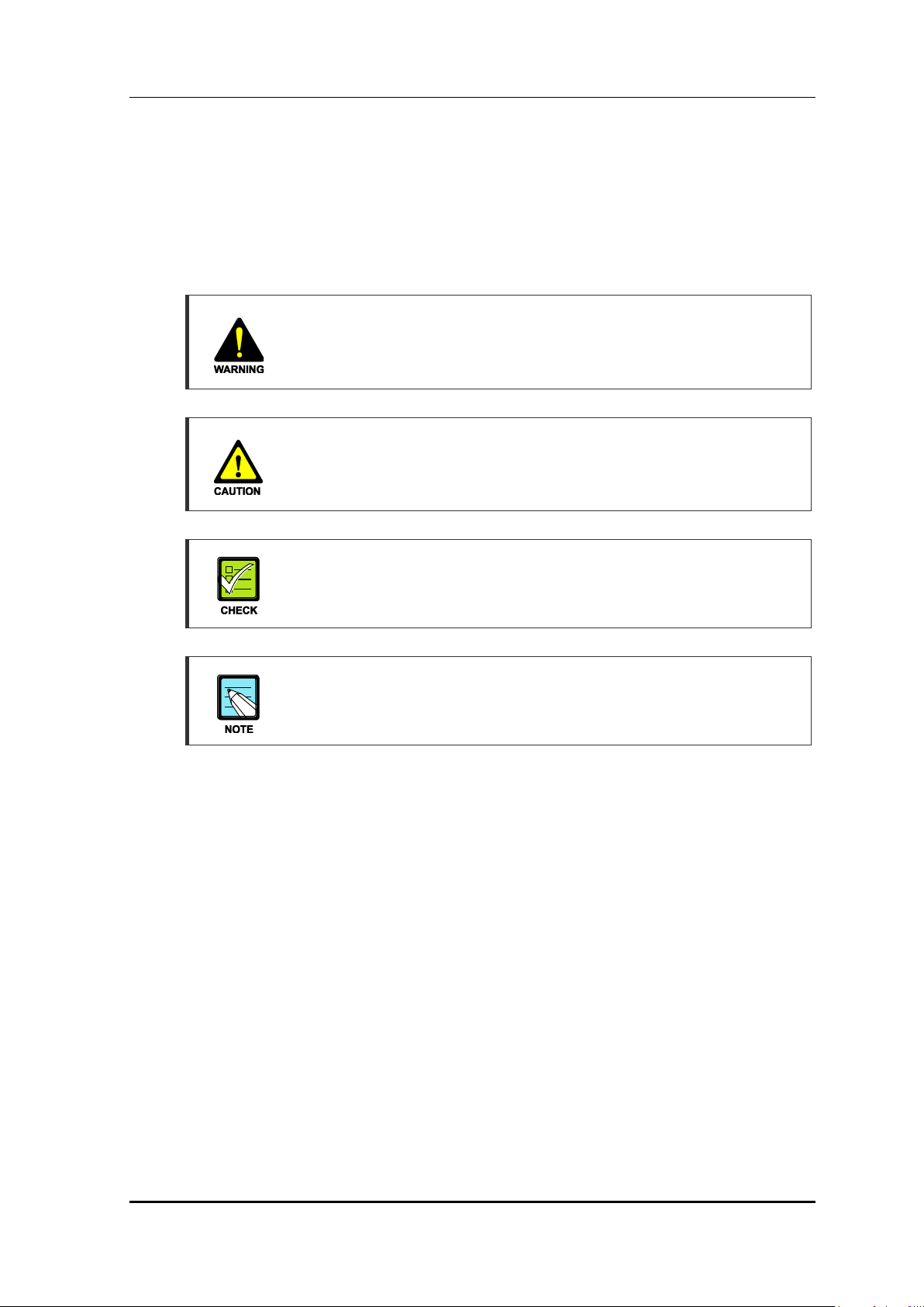
Conventions
The following types of paragraphs contain special information that must be carefully read
and thoroughly understood. Such information may or may not be enclosed in a rectangular
box, separating it from the main text, but is always preceded by an icon and/or a bold title.
WARNING
Provides information or instructions that the reader should follow in order to avoid
personal injury or fatality.
CAUTION
Provides information or instructions that the reader should follow in order to avoid
a service failure or damage to the system.
CHECKPOINT
Provides the operator with checkpoints for stable system operation.
NOTE
Indicates additional information as a reference.
Console Screen Output
The lined box with ‘Courier New’ font will be used to distinguish between the
main content and console output screen text.
‘Bold Courier New’ font will indicate the value entered by the operator on the
console screen.
Samsung Electronics America Page 4 of
117
WEA453e Installation Manual Version 1.0
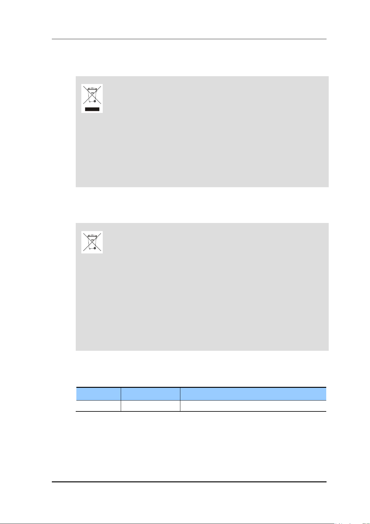
This marking on the product, accessories or literature indicates that the product and
its electronic accessories (e.g. charger, headset, USB cable) should not be disposed
of with other household waste at the end of their working life. To prevent possible
harm to the environment or human health from uncontrolled waste disposal, please
separate these items from other types of waste and recycle them responsibly to
promote the sustainable reuse of material resources.
Household users should contact either the retailer where they purchased this product, or their
local government office, for details of where and how they can take these items for
environmentally safe recycling.
Business users should contact their supplier and check the terms and conditions of the purchase
contract. This product and its electronic accessories should not be mixed with other commercial
wastes for disposal.
Correct disposal of batteries in this product
(Applicable in countries with separate collection systems.)
The marking on the battery, manual or packaging indicates that the battery in this product should
not be disposed of with other household waste. Where marked, the chemical symbols Hg, Cd or
Pb indicate that the battery contains mercury, cadmium or lead above the reference levels in EC
Directive 2006/66.
The battery incorporated in this product is not user replaceable. For information on its
replacement, please contact your service provider. Do not attempt to remove the battery or
dispose it in a fire. Do not disassemble, crush, or puncture the battery. If you intend to discard the
product, the waste collection site will take the appropriate measures for the recycling and
treatment of the product, including the battery.
VERSION
DATE OF ISSUE
REMARKS
1.0
03. 2015.
For U.S. Market
WEEE Symbol Information
BATTERY Symbol Information
Revision History
Samsung Electronics America Page 5 of
117
WEA453e Installation Manual Version 1.0
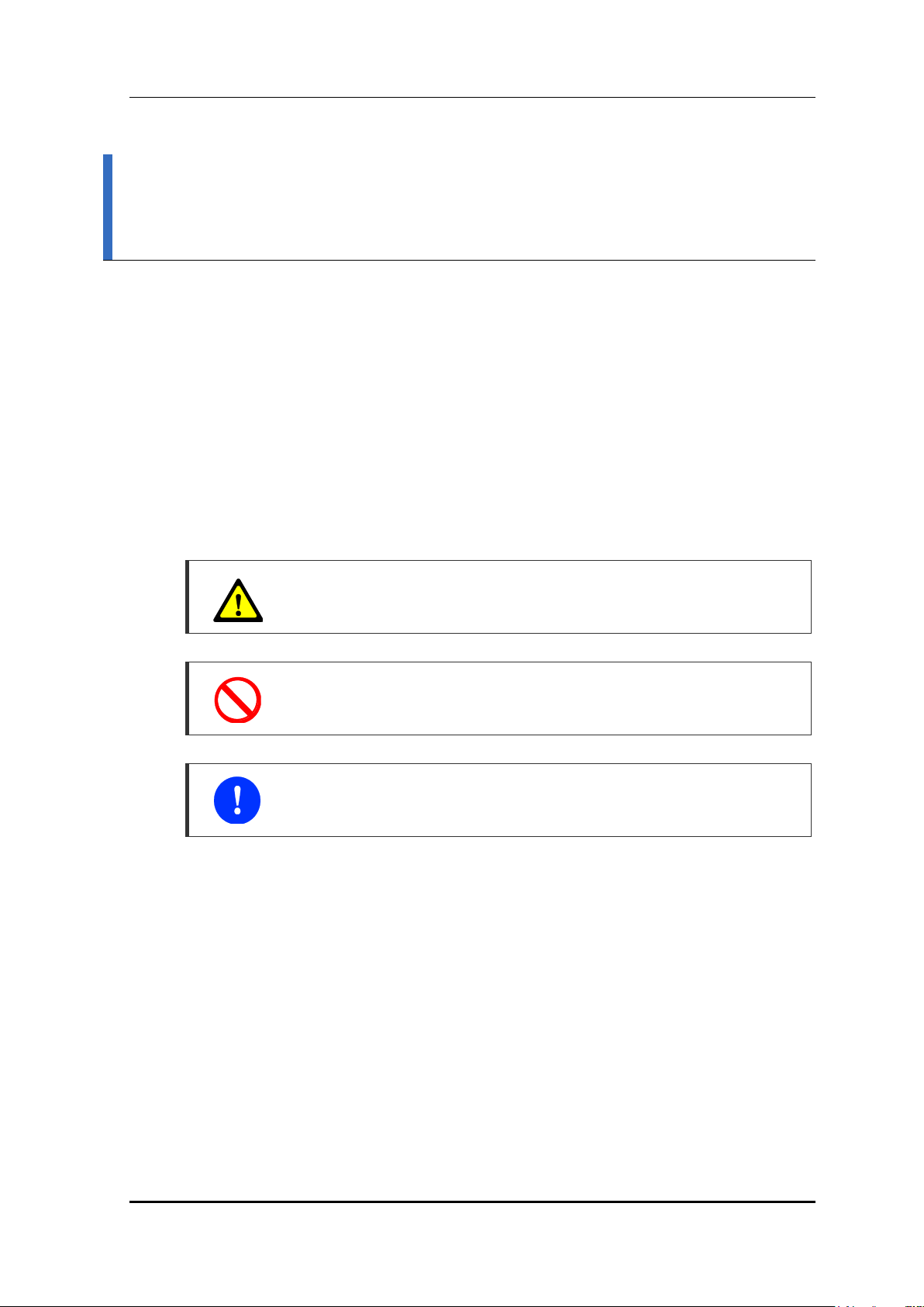
SAFETY CONCERNS
The purpose of the Safety Concerns section is to ensure the safety of users and prevent
property damage. Please read this document carefully for proper use.
Symbols
Caution
Indication of a general caution
Restriction
Indication for prohibiting an action for a product
Instruction
Indication for commanding a specifically required action
Samsung Electronics America Page 6 of
117
WEA453e Installation Manual Version 1.0
CAUTION
WARNING
When measures voltage
When measures the voltage, be careful not to short a circuit since the power is
being supplied.
When mounts/demounts the SDP-U
Make sure to turn off the switch inside the stiffener when mounting/demounting
SDP-U.
When measures voltage
When measures the voltage, be careful not to short a circuit since the power is
being supplied.
When mounts/demounts the SDP-U
Make sure to turn off the switch inside the stiffener when mounting/demounting
SDP-U.
Samsung Electronics America Page 7 of
117
WEA453e Installation Manual Version 1.0
Power and Feeder line
Avoid Contact with Wet Hands
Do not touch the electrical device with your wet hands in order to avoid the risk of
an electric shock.
Turn Off the Power Switch
Make sure that the power is turned off when installing the Outdoor AP
If the power is on while installing the Outdoor AP, serious damages to the system
and injury to the operator may occur.
Connect the Ground Cable
When connecting the cables, make sure to connect the ground cable first. If the
other cables are connected without the ground cable connected first, it may cause
an electric shock causing serious damage or severe injury.
Transportation and Storing
Beware of Fire or Burns
Since there is a risk of fire or burns, make sure to avoid contact with any
flammable materials.
Use Caution When Moving the Product
When installing the product in a narrow space, do not apply any extreme force in
order to avoid any injury caused by bumping into the adjacent equipment or wall.
Samsung Electronics America Page 8 of
117

WEA453e Installation Manual Version 1.0
TABLE OF CONTENTS
Purpose ..................................................................................................................................................... 3
Document Content and Organization ...................................................................................................... 3
Conventions ............................................................................................................................................... 4
Console Screen Output ............................................................................................................................ 4
WEEE Symbol Information ....................................................................................................................... 5
BATTERY Symbol Information ................................................................................................................. 5
Revision History ........................................................................................................................................ 5
Symbols ..................................................................................................................................................... 6
WARNING ................................................................................................................................................. 7
CAUTION .................................................................................................................................................. 7
CHAPTER 1. Preparation 15
1.1 System Design and Interface ..................................................................................................15
1.2 System Specifications .............................................................................................................17
1.3 Installation Safety Procedures ...............................................................................................18
1.4 Installation Tools ......................................................................................................................19
CHAPTER 2. System Installation 20
2.1 Installation Procedure .............................................................................................................20
2.2 Foundation Procedure .............................................................................................................21
2.2.1 System Arrangement .................................................................................................................. 21
2.3 Carrying and Unpacking .........................................................................................................23
2.3.1 Moving the Components ............................................................................................................ 23
2.3.2 Unpacking the Components ...................................................................................................... 23
2.4 Mounting the System ...............................................................................................................24
2.4.1 Wall Mounting ............................................................................................................................. 28
2.4.2 Mounting to a Pole ...................................................................................................................... 39
2.5 Leveling the System ................................................................................................................44
CHAPTER 3. Cables Connect 47
3.1 Connecting the Cables ............................................................................................................47
3.2 Cable Configuration.................................................................................................................52
Samsung Electronics America Page 9 of
117

WEA453e Installation Manual Version 1.0
3.3 Connecting a Ground Cable ...................................................................................................54
3.4 Connecting a Power Cable ......................................................................................................62
3.5 Connecting an Interface Cable ...............................................................................................67
3.5.1 Connecting a PoE Cable ............................................................................................................ 67
3.5.2 Connecting a LAN Cable ........................................................................................................... 72
3.5.3 Connecting the Arrestors ............................................................................................................ 77
3.5.4 Connecting the Patch Antenna Cables ..................................................................................... 81
3.5.5 Connecting the Patch Antenna Cables (Outdoor AP) .............................................................. 85
CHAPTER 4. Inspecting the Installation Status 93
ANNEX A. Connector Assembly 97
A.1 RJ-45 (Shield Type) ..................................................................................................................97
A.2 Finishing the Connector Connection Part by Tape ...............................................................99
ANNEX B. Pressure Terminal Assembly 100
B.1 Preparations ...........................................................................................................................100
B.2 Pressure Reference Table .....................................................................................................101
B.3 Assembling Pressure Terminal.............................................................................................104
ANNEX C. Standard Torque 114
Samsung Electronics America Page 10 of
117

WEA453e Installation Manual Version 1.0
LIST OF FIGURES
Figure 1. Outdoor AP Design ......................................................................................................15
Figure 2. Outdoor AP Interface ...................................................................................................16
Figure 3. Installation Procedure for the Outdoor AP....................................................................20
Figure 4. Wall Type Arrangement ................................................................................................21
Figure 5. Pole Type Arrangement ...............................................................................................22
Figure 6. Assembling the Unit Bracket ........................................................................................24
Figure 7. Assembling the Dipole Antennas (1) ............................................................................25
Figure 8. Assembling the Dipole Antennas (2) ............................................................................26
Figure 9. Assembling the Dipole Antennas (3) ............................................................................27
Figure 10. Marking the Outdoor AP .............................................................................................28
Figure 11. Marking the Adapter ...................................................................................................29
Figure 12. Marking Example .......................................................................................................30
Figure 13. Drilling Example .........................................................................................................31
Figure 14. Mounting the Mount Bracket on the Wall (1) ..............................................................32
Figure 15. Mounting the Mount Bracket on the Wall (2) ..............................................................33
Figure 16. Mounting the Outdoor AP on the Wall (1) ...................................................................34
Figure 17. Mounting the Outdoor AP on the Wall (2) ...................................................................35
Figure 18. Mounting the Outdoor AP on the Wall (3) ...................................................................35
Figure 19. Mounting the Adapter (1) ...........................................................................................36
Figure 20. Mounting the Adapter (2) ...........................................................................................37
Figure 21. Mounting the Outdoor AP on a Pole (1) .....................................................................39
Figure 22. Mounting the Outdoor AP on a Pole (2) .....................................................................40
Figure 23. Mounting the Outdoor AP on a Pole (3) .....................................................................40
Figure 24. Mounting the Outdoor AP on a Pole (4) .....................................................................41
Figure 25. Mounting the Adapter on a Pole (1) ...........................................................................42
Figure 26. Mounting the Adapter on a Pole (2) ...........................................................................43
Figure 27. Using a Spirit Level on a Wall Mount (1) ....................................................................44
Figure 28. Using a Spirit Level on a Wall Mount (2) ....................................................................45
Figure 29. Using a Spirit Level on a Pole Mount (1)....................................................................45
Figure 30. Using a Spirit Level on a Pole Mount (2)....................................................................46
Figure 31. Connecting the System Cables ..................................................................................47
Figure 32. Procedure for Connecting the Cables ........................................................................48
Figure 33. Outdoor AP Connection Cables .................................................................................52
Figure 34. Connecting a Ground Cable to the Outdoor AP (1) ....................................................55
Figure 35. Connecting a Ground Cable to the Outdoor AP (2) ....................................................56
Figure 36. Connecting a Ground Cable to the Outdoor AP (3) ....................................................57
Figure 37. Connecting a Ground Cable to the Arrestor (1) ..........................................................58
Samsung Electronics America Page 11 of
117

WEA453e Installation Manual Version 1.0
Figure 38. Connecting a Ground Cable to the Arrestor (2) ..........................................................59
Figure 39. Connecting a Ground Cable to the Arrestor (3) ..........................................................60
Figure 40. Connecting a Ground Cable to the Patch Antenna ....................................................61
Figure 41. Power Supply Configuration ......................................................................................62
Figure 42. Connecting a Power Cable (1) ...................................................................................64
Figure 43. Connecting a Power Cable (2) ...................................................................................65
Figure 44. Connecting a Power Cable (3) ...................................................................................66
Figure 45. Connecting the PoE Cable (1) ...................................................................................68
Figure 46. Connecting the PoE Cable (2) ...................................................................................69
Figure 47. Connecting the PoE Cable (3) ...................................................................................70
Figure 48. Connecting the PoE Cable (4) ...................................................................................71
Figure 49. Connecting a LAN Cable (1) ...................................................................................... 73
Figure 50. Connecting a LAN Cable (2) ...................................................................................... 74
Figure 51. Connecting a LAN Cable (3) ...................................................................................... 75
Figure 52. Connecting a LAN Cable (4) ...................................................................................... 76
Figure 53. Connecting the Arrestors (1) ......................................................................................78
Figure 54. Connecting the Arrestors (2) ......................................................................................79
Figure 55. Connecting the Arrestors (3) ......................................................................................80
Figure 56. Connecting the Patch Antenna Cables (1) .................................................................81
Figure 57. Connecting the Patch Antenna Cables (2) .................................................................82
Figure 58. Connecting the Patch Antenna Cables (3) .................................................................83
Figure 59. Connecting the Patch Antenna Cables (4) .................................................................84
Figure 60. Patch Antenna Package Components .......................................................................85
Figure 61. Installing on a Wall .....................................................................................................87
Figure 62. Installing on a Pipe.....................................................................................................88
Figure 63. Installing on a Wall Using Brackets ............................................................................90
Figure 64. Installing on a Ceiling .................................................................................................92
Figure 65. Procedure for Inspecting the Installation Status .........................................................93
Figure 66. Assembling the RJ-45 Connector (Shield Type) (1) ...................................................97
Figure 67. Assembling the RJ-45 Connector (Shield Type) (2) ...................................................98
Figure 68. Check Items for Finishing the Connector Connection Part ........................................99
Figure 69. Preparations ............................................................................................................100
Figure 70. Pressure Reference Drawing (Handheld Compressor) ............................................101
Figure 71. Pressure Reference Drawing (Hydraulic Compressor) ............................................102
Figure 72. Stripping Cable Sheath (1) .......................................................................................104
Figure 73. Stripping Cable Sheath (2) .......................................................................................104
Figure 74. Stripping Cable Sheath (3) .......................................................................................105
Figure 75. Stripping Cable Sheath (4) .......................................................................................105
Figure 76. Stripping Cable Sheath (5) .......................................................................................105
Samsung Electronics America Page 12 of
117

WEA453e Installation Manual Version 1.0
Figure 77. Stripping Cable Sheath (6) .......................................................................................106
Figure 78. Fixing Pressure Terminal_Handheld Compressor (1) ..............................................107
Figure 79. Fixing Pressure Terminal_Handheld Compressor (2) ..............................................107
Figure 80. Fixing Pressure Terminal_Handheld Compressor (3) ..............................................107
Figure 81. Fixing Pressure Terminal_Handheld Compressor (4) ..............................................108
Figure 82. Fixing Pressure Terminal_Handheld Compressor (5) ..............................................108
Figure 83. Fixing Pressure Terminal_Hydraulic Press (1) .........................................................109
Figure 84. Fixing Pressure Terminal_Hydraulic Press (2) ......................................................... 11 0
Figure 85. Fixing Pressure Terminal_Hydraulic Press (3) ......................................................... 110
Figure 86. Fixing Pressure Terminal_Hydraulic Press (4) ......................................................... 110
Figure 87. Fixing Pressure Terminal_Hydraulic Press (5) ......................................................... 111
Figure 88. Assembling Heat Shrink Tube (1) ............................................................................ 113
Figure 89. Assembling Heat Shrink Tube (2) ............................................................................ 113
Figure 90. Outdoor AP Selection Guide .................................................................................... 115
LIST OF TABLES
Table 1. Key Specifications ................................................................ .........................................17
Table 2. Power Specifications and Consumption ........................................................................17
Table 3. Dimensions and Weight .................................................................................................17
Table 4. Environmental Conditions ..............................................................................................17
Table 5. Basic Tools ....................................................................................................................19
Table 6. Recommended Clearance Distance When Installing the System ..................................21
Table 7. Components and Tools for Assembling the Unit Bracket ...............................................24
Table 8. Components and Tools for Assembling the Dipole Antennas ........................................25
Table 9. Drill Bit and Hole Depth for Anchor Bolts .......................................................................30
Table 10. Components and Tools for Mounting the Mount Bracket to the Wall ...........................31
Table 11. Components and Tools for Mounting the Outdoor AP ..................................................34
Table 12. Components and Tools for Mounting the Adapter on the Wall .....................................36
Table 13. Components and Tools for Mounting the Outdoor AP ..................................................39
Table 14. Materials and Tools for Mounting the Adapter to a Pole ..............................................41
Table 15. Using a Spirit Level......................................................................................................44
Table 16. Minimum Cable Bend Radius Allowed .........................................................................49
Table 17. Outdoor AP Connection Cables ...................................................................................53
Table 18. Components and Tools Required for Connecting the Ground Cable to the Outdoor AP .54
Table 19. Components and Tools for Connecting the Ground Cable to the Arrestor ...................56
Table 20. Components and Tools for Connecting a Power Cable ...............................................62
Table 21. Power Cable/Connector Pin Map ................................................................................63
Table 22. Components and Tools for Connecting a PoE Cable...................................................67
Samsung Electronics America Page 13 of
117

WEA453e Installation Manual Version 1.0
Table 23. PoE Cable Pin Map .....................................................................................................67
Table 24. Components and Tools for Connecting a LAN Cable ..................................................72
Table 25. LAN Cable Pin Map .....................................................................................................72
Table 26. Components and Tools for Connecting the Arrestors ..................................................77
Table 27. Materials and Tools for Connecting the Patch Antenna Cables ...................................81
Table 28. Inspection Checklist.....................................................................................................94
Table 29. Pressure Reference Table for Pressure Terminal ......................................................101
Table 30. Compressor Specifications per Cable Thickness ......................................................102
Table 31. Standard Torque Value for Tightening Bolts............................................................... 114
Table 32. Brass Bolts Torque Value .......................................................................................... 114
Samsung Electronics America Page 14 of
117
WEA453e Installation Manual Version 1.0
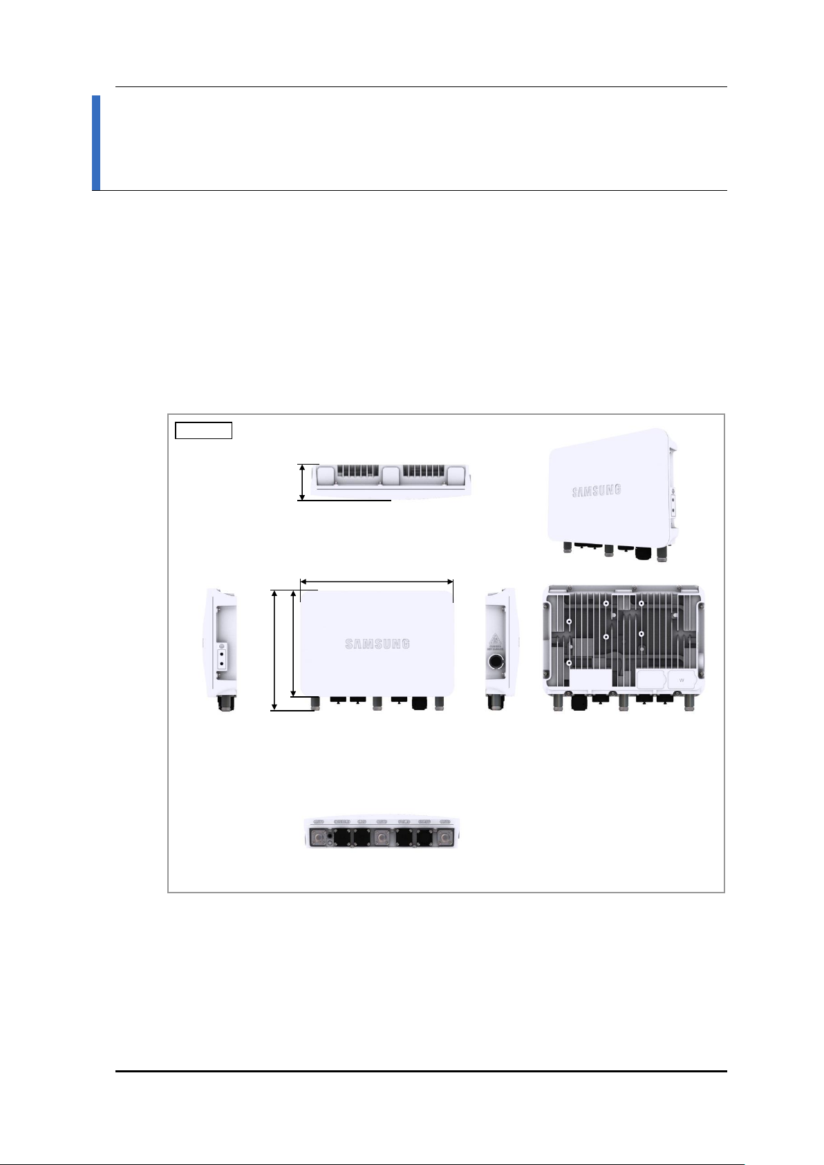
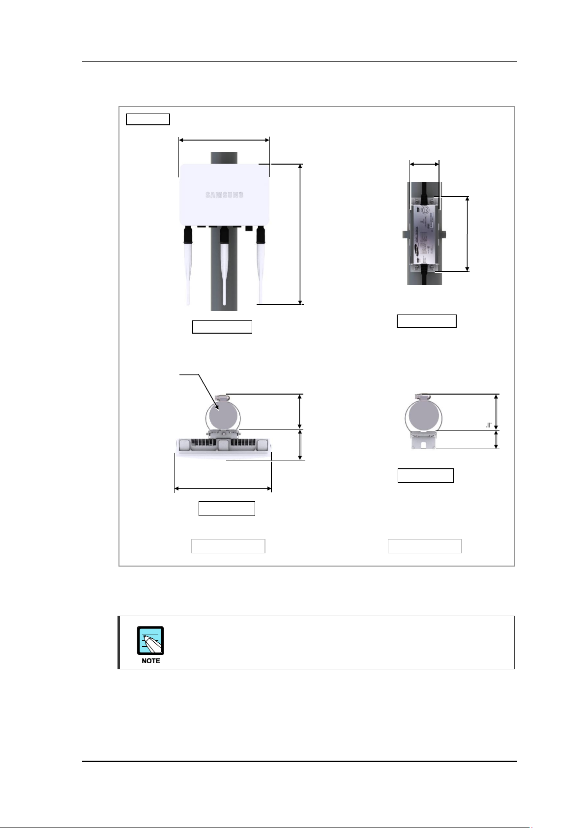
Unit: mm
267
[Bottom View]
≒ 207.7
[Front View]
[Top View]
[Left View]
[Right View]
[Rear View]
57.5
184
CHAPTER 1. Preparation
1.1 System Design and Interface
Design
The design of the Outdoor AP is as follows:
Figure 1. Outdoor AP Design
Samsung Electronics America Page 15 of
117
WEA453e Installation Manual Version 1.0
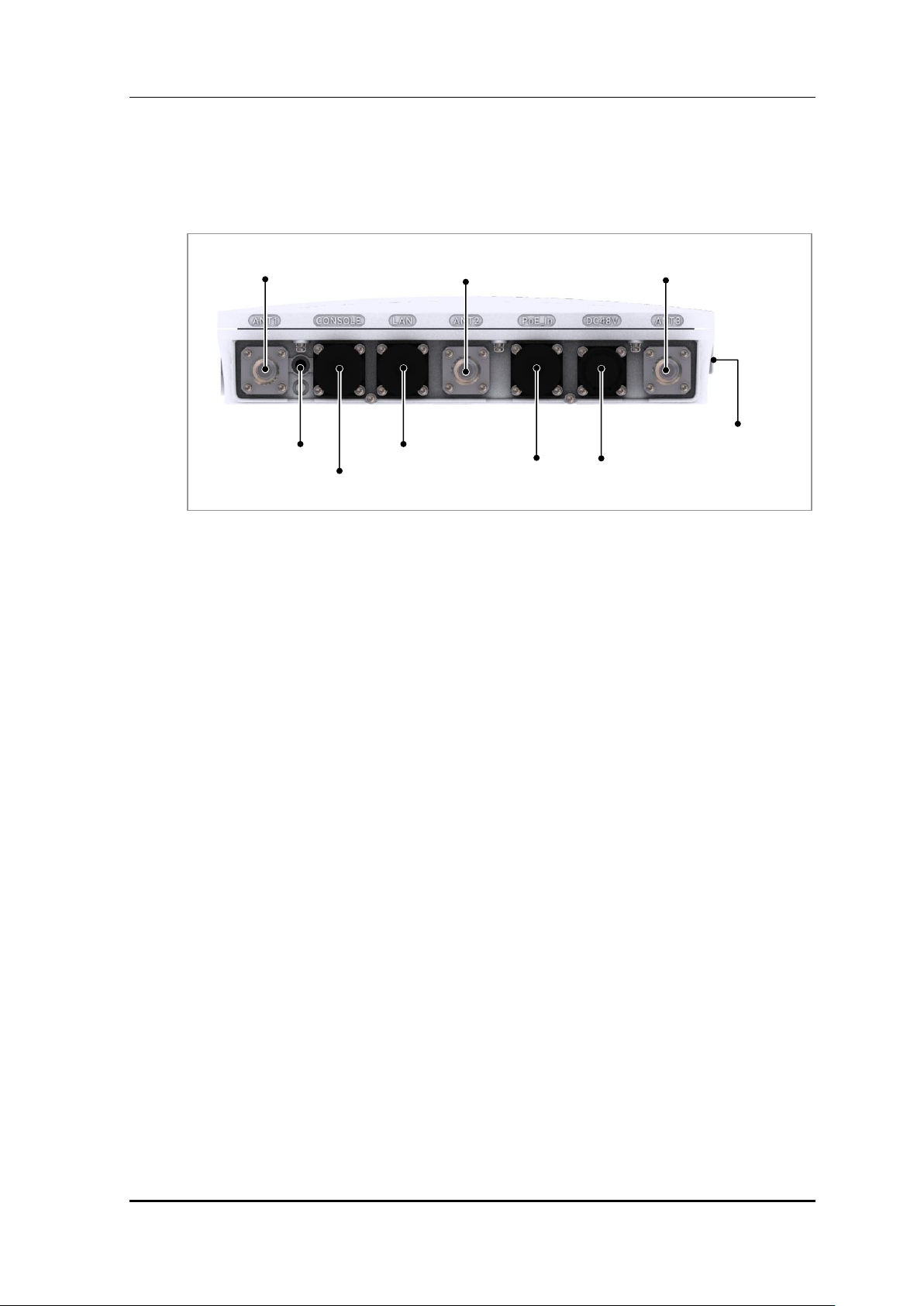
ANT_1
Ground
Terminal
CONSOLE
LAN
PoE
DC 48 V
ANT_2
ANT_3
LED
Interface
The interface and connections for the Outdoor AP are as follows:
Figure 2. Outdoor AP Interface
Samsung Electronics America Page 16 of
117

WEA453e Installation Manual Version 1.0
Item
Specifications
Operating Frequency
2.401-2.4835 GHz, 5.15-5.825 GHz
Radio Technology
IEEE 802.11ac/a/b/g/n
Channel Bandwidth
20, 40, 80 MHz
RF Power
Max 23 dBm (complies the regulatory domain for each country)
Item
Specifications
PoE
IEEE 802.3at
Adapter (optional)
100-240 VAC, 50 Hz, 48 VDC, 1 A
Power Consumption
25.5 W
Item
Specifications
Dimensions (mm)
267 × 184 × 57.5
Weight (kg)
3 kg or less
Item
Specifications
Operating Temperatures
-40°C to 55°C
Humidity
5-100 % (non-condensing)
Cooling Method
Ambient air
Resistance to Dust/Water
IP66 & IP67
1.2 System Specifications
Key Specifications
The key specifications of the Smart AP are as follows:
Table 1. Key Specifications
Power Specifications
The power specifications of the Smart AP are as follows:
Table 2. Power Specifications and Consumption
Dimensions and Weight
The dimensions and weight of the Smart AP are as follows:
Table 3. Dimensions and Weight
Environmental Conditions
The environmental conditions required for the Outdoor AP are as follows:
Table 4. Environmental Conditions
Samsung Electronics America Page 17 of
117
WEA453e Installation Manual Version 1.0
1.3 Installation Safety Procedures
When installing the system, be cautious of the following in order to avoid any safety issues
or accidents:
Before Installing the Product
Post warning signs in the area where the high voltage cables are located.
Post warning signs near the areas where a safety accident may occur.
Block any open spaces, such as connections and scaffolding, by using guardrails or
fences.
During Installation
Proceed with the installation only after all system power has been completely shut off.
When moving or installing the system, be careful not to damage or scratch the boards,
or the cables between the boards, that are mounted on the system.
When installing the system, make sure that the power supply is turned off.
Installing the system with the power turned on may cause serious damages or
fatal injury.
When drilling into a wall, the operator must wear protective gloves and safety
goggles to avoid any injuries caused by splinters.
Do not wear any metal accessories, such as watches or rings, in order to avoid
an electric shock.
All unused ports must be covered with waterproof caps to prevent an inflow of
any foreign substances.
Any outdoor materials (such as the metal band and the screws) must be stainless
steel (STS 304). Otherwise, the metal can become corroded and rust.
After Completing the Installation
Clean up all of the waste materials that accumulated from the installation procedure and
tidy up the area.
Be careful not to damage the cable installation area during the cleaning process.
Be careful to avoid any contact with the power supply by any foreign substance
while cleaning up which may result in a product malfunction.
Samsung Electronics America Page 18 of
117
WEA453e Installation Manual Version 1.0
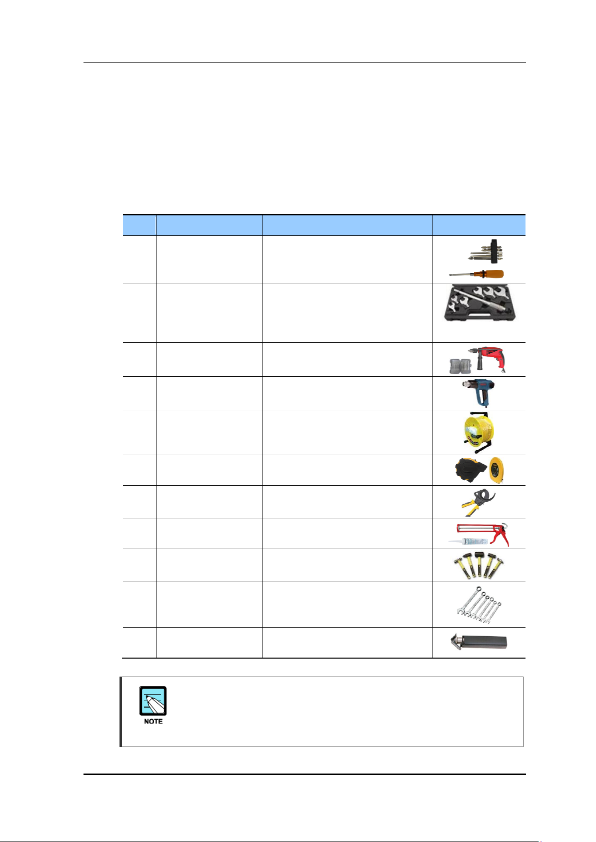
No.
Name
Specification
Image
1
Torque Driver Set
No.0-+ No.3 (M2.6-M6 ‘+’ Screwdriver)
Torx Driver(T20H))
1-50 kgf·cm
2
Torque Wrench Set
M6-M14
- 10-30 kgf·cm
- 490.5-4905 cN·m (100-500 kgf·cm)
Replaceable head
3
Drill/Bit Set
6-17 mm
4
Heating Gun
50-300°C
5
Power Extension Cable
30 m
6
Tape Measure
5 m/50 m
7
Cable Cutter
6-32 mm
8
Silicon Gun/Silicon
Normal/Gray & Colorless
9
Hammers
Still/Rubber/PVC
10
Wrenches
10 mm, 13 mm, 17 mm
19 mm, 24 mm, 36 mm
11
Wire Stripper
6-24 mm
1.4 Installation Tools
Basic tools for installing the product are shown below. Besides these tools, any other tools
necessary for the installation site should be prepared according to the site review before
starting the installation.
Table 5. Basic Tools
These basic tools are subject to change based on the actual conditions of the
Samsung Electronics America Page 19 of
installation site. Be prepared with any other necessary tools, such as a protractor,
compass, ladder, and any additional safety or cleaning equipment that may be
required in accordance with the site conditions.
117
WEA453e Installation Manual Version 1.0
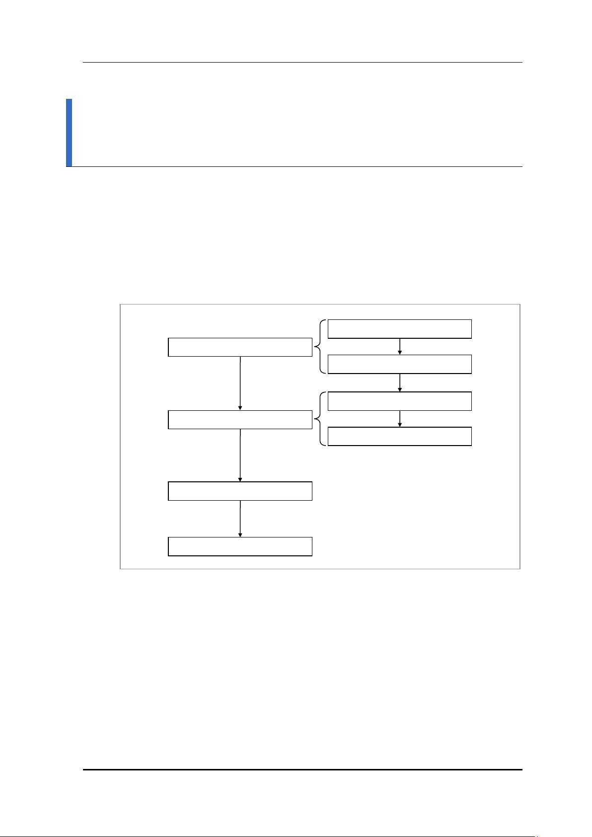
Foundation Procedure
Unpacking and Transporting
Marking and Drilling
System Arrangement
Mounting the System
Leveling the System
Unpacking the Components
Moving the Components
CHAPTER 2. System Installation
2.1 Installation Procedure
The installation procedure for the Outdoor AP is as follows:
Samsung Electronics America Page 20 of
Figure 3. Installation Procedure for the Outdoor AP
117
WEA453e Installation Manual Version 1.0
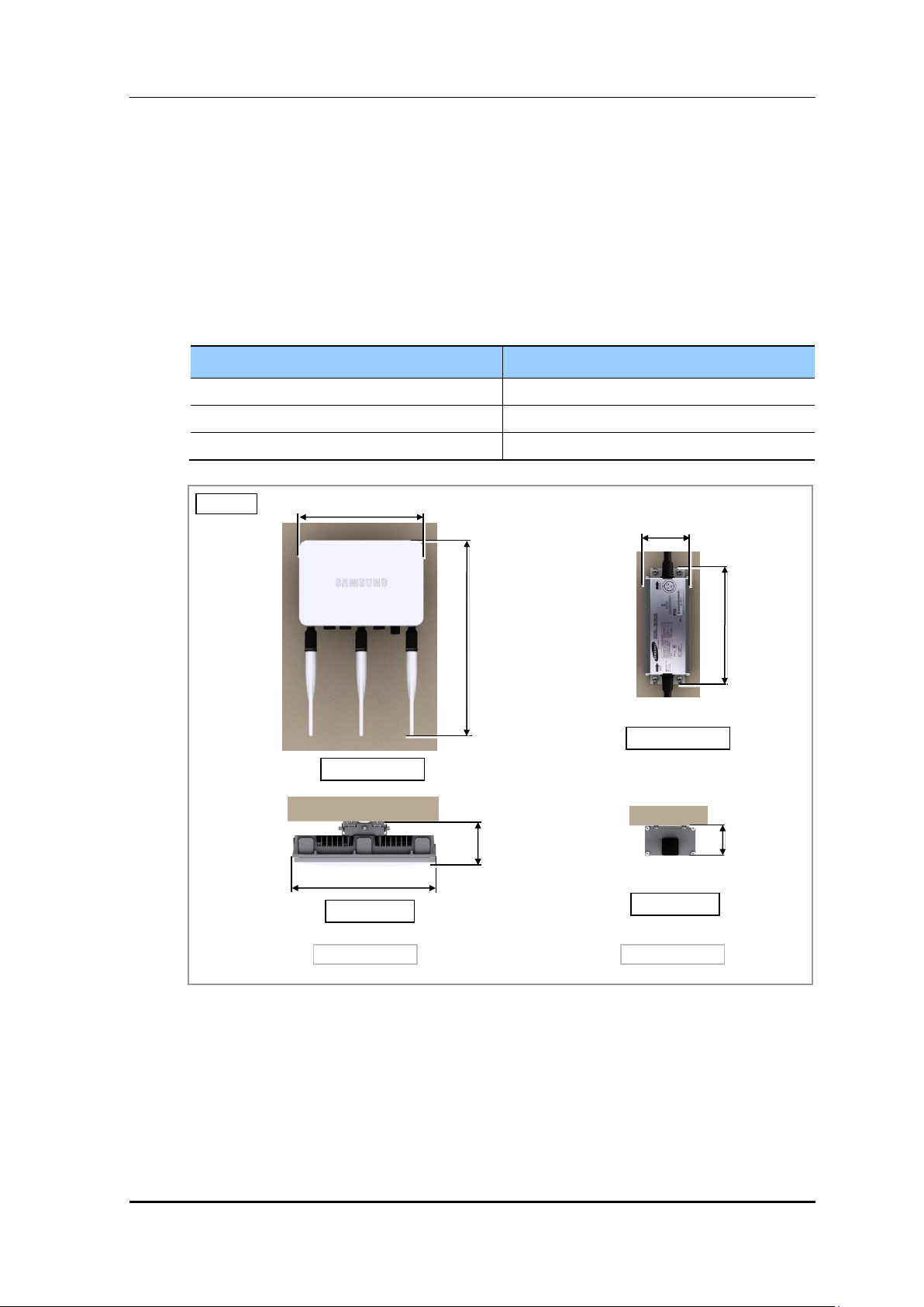
Product Area
Recommended Clearance Distance
Front/Rear
800 mm or further
Side
300 mm or further
Top/Bottom
1,000 mm or further
Unit: mm
267
≒ 411.7
267
[Top View]
[Front View]
≒ 87.5
163.2
61.5
36.3
Outdoor AP
Adapter
[Top View]
[Front View]
2.2 Foundation Procedure
2.2.1 System Arrangement
In order to guarantee the least amount of space for installing, maintaining, or repairing the
system, establish a clear distance from any obstructions.
Table 6. Recommended Clearance Distance When Installing the System
Samsung Electronics America Page 21 of
Figure 4. Wall Type Arrangement
117
WEA453e Installation Manual Version 1.0
Unit: mm
[Top View]
[Front View]
Pole (Ф 101.6)
267
≒ 411.7
≒ 87.5
267
≒ 121.6
Outdoor AP
Adapter
168.2
68.0
≒ 121.6
[Top View]
[Front View]
47
Figure 5. Pole Type Arrangement
The top view of the above image is used when the diameter of the pole is 101.6 mm,
however the measurement may differ depending on the pole diameter.
Samsung Electronics America Page 22 of
117

WEA453e Installation Manual Version 1.0
2.3 Carrying and Unpacking
This process outlines how to carry the system and other components to the installation site
and how to unpack them.
2.3.1 Moving the Components
When bringing in the system components, keep in mind the following:
Firmly secure the components in the transporting vehicle and do not exceed the valid
vibration range (1-500 Hz) while transporting the system.
When the operators carry the system components by hand, they must use a cart or a lift
to move the system to the site and also have enough people to carry them.
Clear an adequate space and remove all obstructions before moving the system.
Avoid any physical impact, dust, humidity, or static electricity that may cause any
system damage while moving it.
2.3.2 Unpacking the Components
When unpacking the components, keep in mind the following:
Do not unpack the components until they arrive at the installation site.
Sort the supplies by job specifications and store the components in a safe place where
they will not disturb the installation.
Start installing the system immediately after unpacking the components. If the
installation cannot be completed immediately, store the system at the installation site.
Unpack the external packaging first.
Unpack the internal packaging after arranging the components in their respective
installation positions.
Do not recycle the unused materials. Dispose of the packaging materials in according
with the local waste disposal regulations.
Samsung Electronics America Page 23 of
117
WEA453e Installation Manual Version 1.0
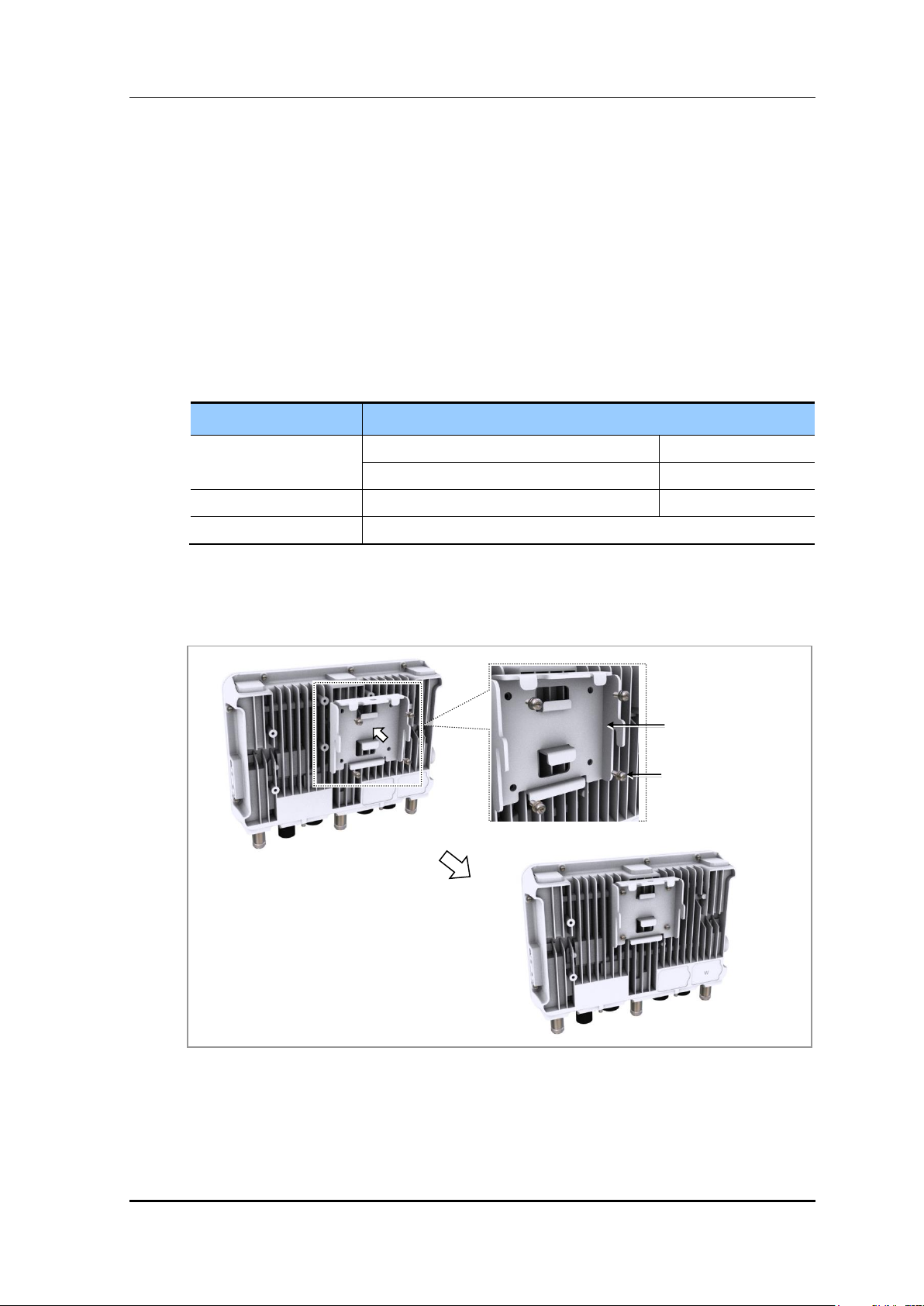
Item
Description
Components
Unit Bracket
1 EA
M4 × L10 Torx Screw (WSP)
4 EA
Regulated Torque Value
M4 Torx Screw
9.52-14.28 kgf·cm
Required Tool
Torque Driver (T20H)
Unit Bracket
Torx Screws (WSP)
2.4 Mounting the System
The following procedure outlines the installation instructions for mounting the Outdoor AP
and adapter to a wall or to a pole:
Assembling the Unit Bracket
1) Prepare the following components:
Table 7. Components and Tools for Assembling the Unit Bracket
2) Fix the unit bracket to the Outdoor AP by matching up each hole and screwing in the 4
torx screws (WSP).
Samsung Electronics America Page 24 of
Figure 6. Assembling the Unit Bracket
117
WEA453e Installation Manual Version 1.0
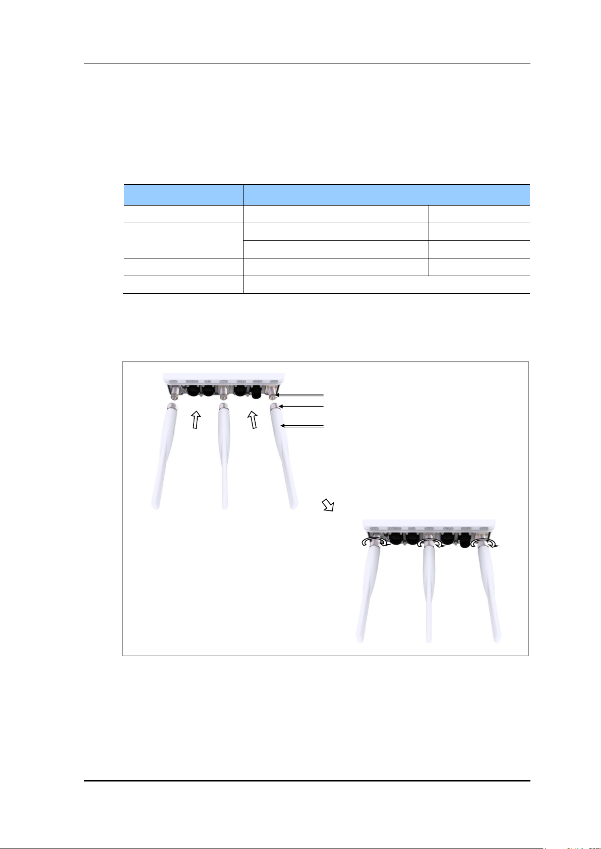
Item
Description
Components
Dipole Antennas
3 EA
Connectors
Outdoor AP
N Type-Female
Dipole Antenna
N Type-Male
Regulated Torque Value
N Type-Male
9-11.3 kgf·cm
Required Tool
Torque Wrench
RF Antenna Port (N Type-Female)
Dipole Antenna
N Type-male connector
Assembling the Dipole Antennas
1) Prepare the following components:
Table 8. Components and Tools for Assembling the Dipole Antennas
2) Connect the 3 dipole antennas to the Outdoor AP connectors (ANT1, ANT2, and
ANT3).
Samsung Electronics America Page 25 of
Figure 7. Assembling the Dipole Antennas (1)
117
WEA453e Installation Manual Version 1.0
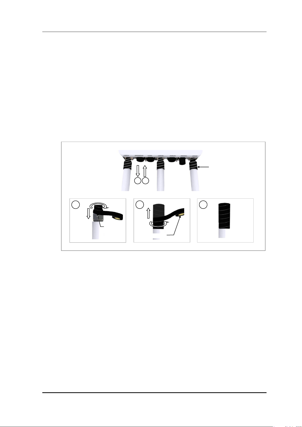
Insulating Tape
2
3
Insulating
Tape
1
Insulating Tape
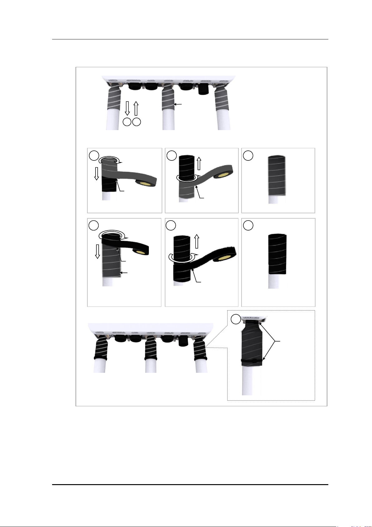
3) Wrap the interlinked parts in at least two layers of insulating tape to cover the metal
after attaching the connector.
4) Wrap insulating tape over the area in at least two layers of butyl tape, starting 10-20 mm
down from the upper end to 10-20 mm below the heat shrink tube.
5) Wrap butyl tape over the area in at least two layers of insulating tape in the same
manner.
6) Tie both ends of the insulating tape using cable ties to make sure they do not become
unwrapped.
Figure 8. Assembling the Dipole Antennas (2)
Samsung Electronics America Page 26 of
117
WEA453e Installation Manual Version 1.0
Butyl Tape
Butyl Tape
4
5
Butyl Tape
6
8
9
7
Insulating Tape
Insulating Tape
Butyl Tape
Cable Tie
10
Figure 9. Assembling the Dipole Antennas (3)
Samsung Electronics America Page 27 of
117

WEA453e Installation Manual Version 1.0
Unit: mm
Plastic Anchor Hole
(Ф 5)
63.9
93.75
184
267
2.4.1 Wall Mounting
Marking
Mark the points where the system is to be installed and the anchor bolts are to be fixed
using an inking line or pen.
When drilling and anchoring the system on the wall without confirming the
horizontal/vertical position of the marked points, the level can only be adjusted by
a small amount.
Then inspect the level of the marked points to check whether they are
horizontal/vertical by referring to 'System Leveling', and adjust them accordingly.
To minimize the margin of marking errors by the operator, it is recommended to
determine the exact placement of the system first. Place the system in the
appropriate place and then mark the locations to fix the anchor bolts using a pen.
Figure 10. Marking the Outdoor AP
Samsung Electronics America Page 28 of
117
WEA453e Installation Manual Version 1.0
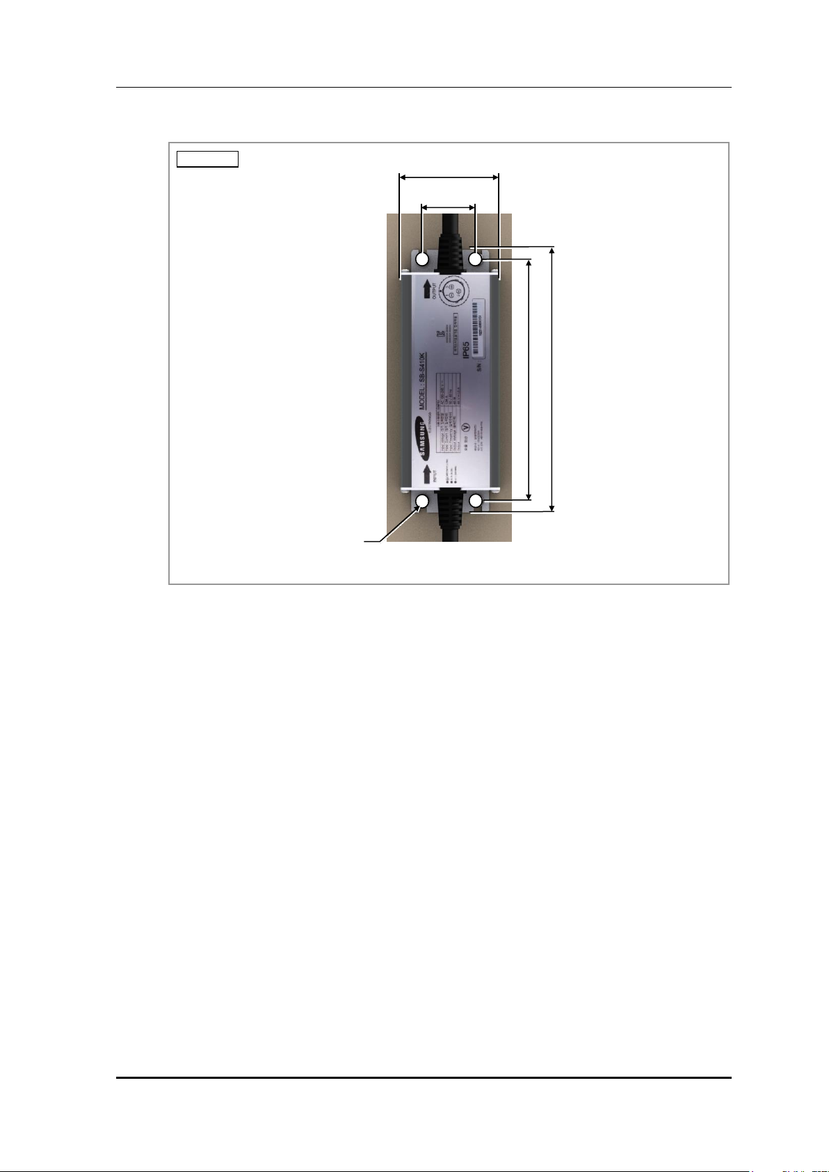
Unit: mm
Plastic Anchor Hole
(Ф 5)
163.2
148
61.5
34
Figure 11. Marking the Adapter
1) After confirming the placement of the system and the correct distances between the
holes, mark the positions on the wall.
2) Draw a horizontal line between the marked holes.
3) Verify the horizontal line is correct by using a spirit level. If it is not level, then adjust
the marked points accordingly.
Samsung Electronics America Page 29 of
117
WEA453e Installation Manual Version 1.0
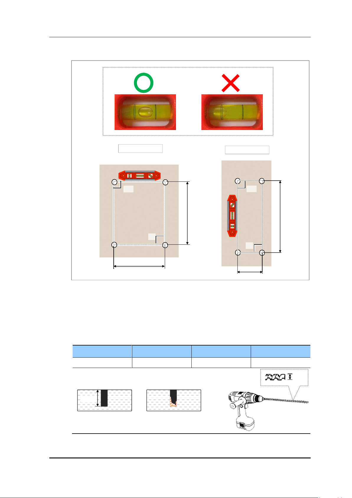
Item
Anchor Bolt
Drill Bit
Hole Depth
Outdoor AP
M4
6 mm
30 mm
63.9 mm
90˚
90˚
93.75 mm
148 mm
Outdoor AP
Adapter
90˚
90˚
34 mm
O
* Remove any foreign substances from inside the drilled hole.
[Cross Section of a Hole]
30 mm
X
6 mm
Figure 12. Marking Example
Drilling
Drill holes where the marked points are for fixing the plastic anchors.
Table 9. Drill Bit and Hole Depth for Anchor Bolts
Samsung Electronics America Page 30 of
117
 Loading...