

Page 1

Ver.
2600-00FK1RGA4
6.0
WEC8500/WEC8050 (APC)
Operation Manual
Page 2

COPYRIGHT
This manual is proprietary to SAMSUNG Electronics Co., Ltd. and is protected by copyright.
No information contained herein may be copied, translated, transcribed or duplicated for any commercial
purposes or disclosed to the third party in any form without the prior written consent of SAMSUNG Electronics
Co., Ltd.
TRADEMARKS
Product names mentioned in this manual may be trademarks and/or registered trademarks of their respective
companies.
This manual should be read and used as a guideline for properly installing and operating the product.
All reasonable care has been made to ensure that this document is accurate. If you have any comments on
this manual, please contact our documentation centre at the following homepage:
Homepage: http://www.samsungdocs.com
© 2013~2014 SAMSUNG Electronics Co., Ltd. All rights reserved.
Page 3

INTRODUCTION
Purpose
This manual describes the overview, management, and setup of WEC8500/WEC8050 that
is a Samsung Wireless Enterprise (W-EP) Access Point Controller (APC). This manual is
written for WEC8500 version 1.4.4, WEC8050 version 1.0.0.
INTRODUCTION
Document Content and Organization
This manual consists of ten Chapters, three Annexes, and a list of Abbreviations.
CHAPTER 1. Access Point Controller System Overview
This chapter describes the main functions, network configuration, external configuration
and service scenario of APC.
CHAPTER 2. Basic System Configuration
This chapter describes how to configure to use Command Line Interface (CLI) and Web UI.
CHAPTER 3. Data Network Function
This chapter describes how to set up the data network such as interface, Virtual Local Area
Network (VLAN), L3, or Quality of Service (QoS), etc. of APC.
CHAPTER 4. AP Connection Management
This chapter describes the connection management function of APC and Samsung W-EP
wireless LAN Access Point (AP).
CHAPTER 5. WLAN Management
This chapter describes how to set up the Wireless Local Area Network (WLAN) of APC.
CHAPTER 6. Wi-Fi Configuration
This chapter describes how to configure the Wireless Fidelity (Wi-Fi) of APC, QoS, and
country code.
© SAMSUNG Electronics Co., Ltd.
page 3 of 628
Page 4

INTRODUCTION
CHAPTER 7. WLAN Additional Service
This chapter describes how to set up WLAN additional services available in the APC.
CHAPTER 8. Security
This chapter describes how to set up security related setting such as Remote Authentication
Dial-In User Service (RADIUS) server available in the APC, unauthorized AP detection
and blocking function, guest access, WEB pass-through, Network Address Translation
(NAT), firewall function, etc.
CHAPTER 9. IP Application
This chapter describes the Internet Protocol (IP) application functions available in the APC
such as Domain Naming Service (DNS), Network Time Protocol (NTP), File Transfer
Protocol (FTP)/sFTP, or Telnet/SSH.
CHAPTER 10. System Management
This chapter describes the various system management functions available in the APC.
ANNEX A. CLI Command Structure
Command structure available in the CLI of APC.
ANNEX B. Open Source Announcement (WEC8500/WEC8050)
Open source list used in the APC and its license notice.
ANNEX C. Open Source Announcement (WEA302/WEA303/WEA312/
WEA313/WEA403/WEA412)
Open source list used in the Samsung W-EP wireless LAN AP and its license notice.
ABBREVIATION
Describes the acronyms used in this manual.
Conventions
The following types of paragraphs contain special information that must be carefully read
and thoroughly understood. Such information may or may not be enclosed in a rectangular
box, separating it from the main text, but is always preceded by an icon and/or a bold title.
NOTE
Indicates additional information as a reference.
© SAMSUNG Electronics Co., Ltd.
page 4 of 628
Page 5

Console Screen Output
VERSION
DATE OF ISSUE
REMARKS
6.0
12. 2014.
Updated the content overall in accordance with the
package version 2.4.0
5.0
05. 2014.
Updated the content overall in accordance with the
package version 2.0.0
4.0
01. 2014.
- Changed contents
1.3.1 WEC8500 Configuration and Functions
4.2.6.3 Tech Support Information
3.0
10. 2013.
- Updated the content overall in accordance with the
package version (WEC8500 version 1.4.4, WEC8050
version 1.0.0)
- Added contents for WEC8050
2.0
06. 2013.
- Updated the content overall in accordance with the
package version 1.3.0
- Added contents
3.4.6 OS-AWARE
7.4.2 DPC Configuration
7.4.3 DCS Configuration
7.4.4 CHDC Configuration
- Changed contents
7.10 Clustering
10.8.2 System Upgrade
1.0
03. 2013.
First Version
The lined box with ‘Courier New’ font will be used to distinguish between the
main content and console output screen text.
‘Bold Courier New’ font will indicate the value entered by the operator on the
console screen.
Revision History
INTRODUCTION
© SAMSUNG Electronics Co., Ltd.
page 5 of 628
Page 6

TABLE OF CONTENTS
TABLE OF CONTENTS
INTRODUCTION 3
Purpose ....................................................................................................................................... 3
Document Content and Organization .......................................................................................... 3
Conventions ................................................................................................................................ 4
Console Screen Output ............................................................................................................... 5
Revision History .......................................................................................................................... 5
CHAPTER 1. Access Point Controller System Overview 21
1.1 APC Overview .......................................................................................................................... 21
1.2 Network Configuration ............................................................................................................ 23
1.3 APC Configuration and Functions ......................................................................................... 26
1.3.1 WEC8500 Configuration and Functions ...................................................................... 26
1.3.2 WEC8050 Configuration and Functions ...................................................................... 30
1.4 APC Application Configuration and Service Scenario ......................................................... 32
1.4.1 Basic Configuration ..................................................................................................... 32
1.4.2 Configuration of Multiple APC for Redundancy ........................................................... 33
1.4.3 Clustering Configuration using Multiple APC (WEC8500) ........................................... 34
1.4.4 Configuration of Multiple Sites Consisting of Headquarter and Branches ................... 37
1.5 NAT Configuration between AP and APC .............................................................................. 39
CHAPTER 2. Basic System Configuration 40
2.1 Basic System Configuration ................................................................................................... 40
2.1.1 CLI Connection ........................................................................................................... 40
2.1.2 Managing Operator Account ........................................................................................ 41
2.1.3 APC Management Port Configuration ......................................................................... 42
2.1.4 SNMP Community Configuration................................................................................. 42
2.1.5 CLI Basic Usage ......................................................................................................... 42
2.2 Using Web UI ........................................................................................................................... 45
2.2.1 Web UI Connection ..................................................................................................... 45
2.2.2 WEC Main Window ..................................................................................................... 46
2.2.3 Managing Operator Account ........................................................................................ 47
© SAMSUNG Electronics Co., Ltd.
page 6 of 628
Page 7

TABLE OF CONTENTS
2.3 Initial Setup Wizard ..................................................................................................................48
2.3.1 Overview......................................................................................................................48
2.3.2 Connecting ..................................................................................................................48
2.3.3 How to Use ..................................................................................................................49
CHAPTER 3. Data Network Function 52
3.1 Port Configuration ...................................................................................................................52
3.1.1 Port management ........................................................................................................52
3.2 Interface Configuration ...........................................................................................................56
3.2.1 Interface management .................................................................................................56
3.2.2 Managing Interface Group ...........................................................................................59
3.3 VLAN Configuration.................................................................................................................61
3.3.1 VLAN ...........................................................................................................................61
3.3.2 Bridge ..........................................................................................................................63
3.3.3 Spanning Tree .............................................................................................................66
3.4 Layer 3 Protocol Configuration ..............................................................................................70
3.4.1 IP Address Configuration .............................................................................................70
3.4.2 Static Routing Configuration ........................................................................................70
3.4.3 IP Multicast Routing Configuration ..............................................................................71
3.4.4 PIM Configuration ........................................................................................................72
3.4.5 OSPF Configuration ....................................................................................................72
3.4.6 VRRP Configuration .................................................................................................. 110
3.4.7 Configuring IPWATCHD............................................................................................. 113
3.5 QoS ..................................................................................................................................... 114
3.5.1 ACL Configuration ..................................................................................................... 114
3.5.2 Class-map Configuration ................................ ........................................................... 118
3.5.3 Policy-map Configuration........................................................................................... 119
3.5.4 Service Policy Configuration ......................................................................................120
3.5.5 Time Profile................................................................................................................121
3.5.6 OS-AWARE ...............................................................................................................124
3.6 Multicast to Unicast ...............................................................................................................127
3.7 IP Multicast Configuration ....................................................................................................127
3.7.1 IP Multicast Routing Configuration ............................................................................127
3.7.2 PIM Configuration ......................................................................................................127
3.8 IGMP Snooping ......................................................................................................................130
3.9 Deep Packet Inspection .........................................................................................................133
3.9.1 Configuring Profile and Application Rule ...................................................................133
© SAMSUNG Electronics Co., Ltd.
page 7 of 628
Page 8

TABLE OF CONTENTS
3.9.2 Configuring Application Group ................................................................................... 134
3.9.3 Checking Statistics by Category ................................................................................ 134
CHAPTER 4. AP Connection Management 139
4.1 APC Management .................................................................................................................. 139
4.1.1 Managing APC List .................................................................................................... 139
4.1.2 Management Interface Configuration ........................................................................ 141
4.1.3 CAPWAP Configuration............................................................................................. 142
4.1.4 AP Registration (Auto Discovery) Configuration ........................................................ 144
4.1.5 Managing AP File Transmission ................................................................................ 145
4.1.6 APC Redundancy Configuration ............................................................................... 145
4.2 AP Management ..................................................................................................................... 151
4.2.1 AP Group Configuration ................................ ............................................................ 151
4.2.2 Configuring Remote AP Group .................................................................................. 167
4.2.3 AP Time Synchronization per Group ......................................................................... 173
4.2.4 AP Configuration ....................................................................................................... 175
4.2.5 Information Management .......................................................................................... 186
4.2.6 Outdoor AP Configuration ......................................................................................... 189
4.2.7 AP Package Upgrade ................................................................................................ 190
4.2.8 Remote AP Package Upgrade .................................................................................. 195
CHAPTER 5. WLAN Management 204
5.1 WLAN Configuration ............................................................................................................. 204
5.1.1 Basic WLAN Configuration ........................................................................................ 204
5.1.2 WLAN Additional Configuration ................................................................................. 207
5.1.3 WLAN-based ACL Configuration ............................................................................... 209
5.1.4 Managing Root Service ............................................................................................. 211
5.1.5 MCS Configuration Management by WLAN .............................................................. 214
5.2 Local Switching ..................................................................................................................... 217
5.3 Security and Authentication ................................................................................................. 220
5.3.1 Initialization of WLAN Security Function.................................................................... 220
5.3.2 WPA/WPA2 PSK Configuration ................................................................................. 222
5.3.3 WPA/WPA2 802.1x Configuration ............................................................................. 225
5.3.4 Static WEP Configuration .......................................................................................... 229
5.3.5 Dynamic WEP Configuration ..................................................................................... 231
5.4 DHCP Configuration ................................................................ .............................................. 234
5.4.1 DHCP Server ............................................................................................................ 234
5.4.2 DHCP Relay .............................................................................................................. 242
© SAMSUNG Electronics Co., Ltd.
page 8 of 628
Page 9

TABLE OF CONTENTS
5.4.3 DHCP Proxy ..............................................................................................................243
5.4.4 Option 82 Configuration .............................................................................................244
5.4.5 Primary/Secondary Server Configuration ..................................................................246
5.5 Radio Service Configuration .................................................................................................249
CHAPTER 6. Wi-Fi Configuration 251
6.1 802.11a/b/g/n/ac Radio Property ...........................................................................................251
6.1.1 802.11a/b/g Configuration ..........................................................................................251
6.1.2 802.11n Configuration ................................................................................................256
6.1.3 802.11ac Configuration ..............................................................................................257
6.2 Wi-Fi QoS Configuration .......................................................................................................259
6.2.1 QoS Configuration of Wireless Terminal ....................................................................259
6.2.2 QoS Configuration of AP............................................................................................261
6.2.3 Configuring QoS Profile of a Specific Terminal ..........................................................265
6.2.4 Voice Optimization Configuration ...............................................................................267
6.3 802.11h Configuration ...........................................................................................................268
6.4 Country Code .........................................................................................................................270
CHAPTER 7. WLAN Additional Services 274
7.1 Managing Wireless Terminal .................................................................................................274
7.1.1 Information Retrieval Functions .................................................................................274
7.1.2 Connection History related Configuration ................................................................ ..275
7.2 Handover Management .........................................................................................................276
7.2.1 Connection History Information .................................................................................276
7.2.2 AirMove Configuration ...............................................................................................276
7.2.3 Inter APC Handover Configuration ............................................................................278
7.3 Call Admission Control (CAC) Configuration ......................................................................279
7.3.1 SIP ALG Configuration ...............................................................................................279
7.3.2 Voice CAC Configuration ...........................................................................................281
7.3.3 Video CAC Configuration ...........................................................................................283
7.4 Radio Resource Management (RRM) ...................................................................................285
7.4.1 RRM Configuration ....................................................................................................285
7.4.2 DPC Configuration .....................................................................................................286
7.4.3 DCS Configuration .....................................................................................................288
7.4.4 CHDC Configuration ..................................................................................................290
7.4.5 Sleeping Cell Detection .............................................................................................294
7.4.6 Energy Saving Groups ...............................................................................................296
© SAMSUNG Electronics Co., Ltd.
page 9 of 628
Page 10

TABLE OF CONTENTS
7.4.7 Energy Saving Auto Classification ............................................................................. 297
7.5 Location Tracking .................................................................................................................. 300
7.6 Spectrum Analysis ................................................................................................................ 301
7.6.1 Retrieving Spectrum Analysis Data ........................................................................... 301
7.6.2 Spectrum Analysis Configuration ............................................................................... 304
7.6.3 Interference Type Configuration ................................................................................ 306
7.7 Controlling Usage per User .................................................................................................. 307
7.8 Remote Packet Capture ........................................................................................................ 309
7.9 Clustering ............................................................................................................................... 311
7.10 Limiting the Number of Connected Users ........................................................................... 315
7.10.1 Limiting Connections per Radio ................................................................................ 315
7.10.2 Connection Limitation per WLAN .............................................................................. 316
7.11 Voice Statistics and Communication Failure Detection ..................................................... 318
7.11.1 Voice Statistics Function ............................................................................................ 318
7.11.2 Detecting WLAN-based Communication Failure ....................................................... 320
7.12 Voice Signal and Media Monitoring ..................................................................................... 321
7.12.1 Checking Voice Related Wireless Information ........................................................... 321
7.12.2 Checking Voice Related Quality Information ............................................................. 326
7.13 Multicast Stream Admission Control ................................................................................... 329
7.13.1 Configuring Admission Control .................................................................................. 329
7.14 Wi-Fi Band Steering .............................................................................................................. 331
7.14.1 Activating Band Steering Function ............................................................................ 331
7.15 Wi-Fi Load Balancing ............................................................................................................ 334
7.15.1 Activating Load Balancing Function .......................................................................... 334
7.16 Station-based Adaptive Load Balancing ............................................................................. 336
7.16.1 Basic Setting of Station-based Adaptive Load Balancing .......................................... 336
7.16.2 Setting AP Group Parameter ..................................................................................... 337
7.16.3 Setting AP Parameters .............................................................................................. 339
CHAPTER 8. Security 341
8.1 RADIUS Server Configuration .............................................................................................. 341
8.1.1 External RADIUS Server ........................................................................................... 341
8.1.2 Internal RADIUS Server ............................................................................................ 347
8.2 Unauthorized AP/Terminal Detection and Blocking ........................................................... 351
8.2.1 Enabling Detection Function ..................................................................................... 351
8.2.2 Detection ................................................................................................................... 352
© SAMSUNG Electronics Co., Ltd.
page 10 of 628
Page 11

TABLE OF CONTENTS
8.2.3 Enabling Blocking Function .......................................................................................370
8.2.4 Blocking .....................................................................................................................370
8.3 Captive Portal .........................................................................................................................374
8.3.1 Configuring Guest Authentication ..............................................................................374
8.3.2 Configuring Guest ACL ..............................................................................................376
8.3.3 Configuring Web Authentication ................................................................................378
8.3.4 Configuring Web Authentication on MAC Authentication Failure ...............................381
8.3.5 Configuring Web Pass-through ..................................................................................385
8.3.6 Configuring One Time Redirection .............................................................................387
8.3.7 Redirection Address Format ......................................................................................389
8.4 NAT and Firewall Configuration............................................................................................390
8.4.1 Firewall Configuration ................................................................................................390
8.4.2 Access List Configuration ................................ ..........................................................391
8.4.3 NAT Configuration .....................................................................................................392
8.5 MAC Filter ...............................................................................................................................396
8.6 Operator Authentication through Interoperation with TACACS+ Server ..........................399
8.6.1 Configuring External TACACS+ Server .....................................................................399
8.6.2 Configuring Authentication Type of Operator Account ...............................................402
8.7 Role Based Access Control ................................................................................................ ..403
8.7.1 Configuring Role Profile .............................................................................................403
8.7.2 Configuring Derivation Profile ....................................................................................404
8.7.3 Configuring ACL Profile .............................................................................................407
8.7.4 Configuration Synchronization (Remote AP Group)................................................... 411
8.8 External BYOD Server ...........................................................................................................414
8.8.1 Configuring External BYOD Server ...........................................................................414
8.8.2 Captive Portal Configuration ......................................................................................416
CHAPTER 9. IP Application 419
9.1 DNS .....................................................................................................................................419
9.1.1 DNS Client Configuration...........................................................................................419
9.1.2 DNS Proxy Configuration...........................................................................................420
9.2 NTP .....................................................................................................................................422
9.3 FTP/sFTP ................................................................................................................................425
9.4 Telnet/SSH ..............................................................................................................................428
9.5 Utilities ................................ ................................ ................................................................ ....430
© SAMSUNG Electronics Co., Ltd.
page 11 of 628
Page 12

TABLE OF CONTENTS
CHAPTER 10. System Management 431
10.1 SNMP Configuration .............................................................................................................. 431
10.1.1 SNMP Community ..................................................................................................... 431
10.1.2 SNMP Trap ................................................................................................................ 432
10.2 System Management ................................................................ ................................ ............. 434
10.2.1 Retrieving System Information .................................................................................. 434
10.2.2 System Reboot ................................................................................................ .......... 439
10.3 System Resource Management ........................................................................................... 441
10.3.1 Retrieving System Status .......................................................................................... 441
10.3.2 Retrieving and Configuring Threshold ....................................................................... 444
10.4 Managing Alarm and Event ................................................................................................... 445
10.4.1 Retrieving Current Alarm ........................................................................................... 446
10.4.2 Retrieving History ...................................................................................................... 447
10.4.3 External Transmission Configuration ......................................................................... 449
10.4.4 Alarm Filter and Level Configuration ......................................................................... 449
10.5 Managing Traffic Performance ............................................................................................. 451
10.5.1 Managing History Information ................................................................................... 451
10.5.2 Managing Real-time Information Collection............................................................... 452
10.6 Managing License Key .......................................................................................................... 453
10.6.1 Managing SLM License (Activation) Key ................................................................... 453
10.6.2 Managing Old License Key ....................................................................................... 456
10.7 Syslog Configuration ............................................................................................................ 459
10.8 Upgrade .................................................................................................................................. 461
10.8.1 Checking Package Version ....................................................................................... 461
10.8.2 System Upgrade ....................................................................................................... 461
10.9 Configuration Management .................................................................................................. 464
10.10 Debug and Diagnosis ............................................................................................................ 466
10.10.1 Process ..................................................................................................................... 466
10.10.2 Retrieving Crash Information ..................................................................................... 468
10.11 File Management ................................................................................................................... 471
10.11.1 Retrieving Configuration of Current Directory ............................................................ 471
10.11.2 Retrieving Directory List ............................................................................................ 472
10.11.3 Revising File .............................................................................................................. 473
10.11.4 Retrieve File Content................................................................................................. 473
10.11.5 File Download and Upload ........................................................................................ 474
10.11.6 Package File ............................................................................................................. 474
10.11.7 Retrieving Storage Media .......................................................................................... 476
© SAMSUNG Electronics Co., Ltd.
page 12 of 628
Page 13

TABLE OF CONTENTS
10.11.8 Managing File in Web UI ...........................................................................................477
10.11.9 Statistics Function ......................................................................................................480
ANNEX A. CLI Command Structure 522
A.1 configure ................................................................................................................................522
A.2 show........................................................................................................................................552
A.3 clear ........................................................................................................................................564
A.4 debug ................................ ......................................................................................................566
A.5 file............................................................................................................................................569
A.6 Etc ...........................................................................................................................................569
ANNEX B. Open Source Announcement (WEC8500/WEC8050) 570
ANNEX C. Open Source Announcement (WEA302/WEA303/
WEA312/WEA313/WEA403/WEA412) 599
ABBREVIATION 624
© SAMSUNG Electronics Co., Ltd.
page 13 of 628
Page 14

LIST OF FIGURES
Figure 1. System Structure for Wireless Enterprise Solution ...................................................... 22
Figure 2. W-EP Network Configuration ....................................................................................... 23
Figure 3. WEC8500 Interface-Front/Back ................................................................................... 26
Figure 4. System LED Configuration .......................................................................................... 26
Figure 5. Management Port Configuration .................................................................................. 27
Figure 6. Optic port configuration ............................................................................................... 28
Figure 7. Power module configuration ................................................................ ........................ 29
Figure 8. WEC8050 interface-Front/Back ................................................................................... 30
Figure 9. Status LED configuration ............................................................................................. 30
Figure 10. Ethernet Port Configurations ..................................................................................... 31
Figure 11. Basic Configuration of W-EP Wireless LAN System .................................................. 32
Figure 12. Example of W-EP Wireless LAN System Configuration for Redundancy .................. 33
TABLE OF CONTENTS
Figure 13. Example of W-EP Wireless LAN System Configuration for Distributed Clustering
Service ...................................................................................................................... 35
Figure 14. Example of W-EP Wireless LAN System Configuration for Centralized Clustering
Service ...................................................................................................................... 36
Figure 15. Example of W-EP Wireless LAN System Configuration for Multiple Sites consisting of
Headquarter and Branches ....................................................................................... 37
Figure 16. AP-APC NAT Environment Configuration Diagram .................................................... 39
Figure 17. Web UI Connection Window ...................................................................................... 45
Figure 18. WEC Main Window .................................................................................................... 46
Figure 19. Operator Account Management Window ................................................................... 47
Figure 20. Operator Account Addition Window ........................................................................... 47
Figure 21. Initial Setup Wizard Welcome Screen ....................................................................... 49
Figure 22. Move to the setup step of the initial setup wizard ...................................................... 49
Figure 23. Port Management Window ........................................................................................ 54
Figure 24. Port Configuration Change Window .......................................................................... 55
Figure 25. Interfaces Window (1) ................................................................................................ 57
Figure 26. Interfaces Window (2) ................................................................................................ 57
Figure 27. Interfaces Window (3) ................................................................................................ 58
Figure 28. Interface Group Window (1) ...................................................................................... 59
Figure 29. Interface Group Window (2) ...................................................................................... 60
Figure 30. Spanning Tree Configuration Window (1) .................................................................. 68
Figure 31. Spanning Tree Configuration Window (2) .................................................................. 69
Figure 32. Spanning Tree Configuration Window (3) .................................................................. 69
Figure 33. Static Routing Configuration Window ........................................................................ 71
Figure 34. OSPF Configuration Window ..................................................................................... 73
© SAMSUNG Electronics Co., Ltd.
page 14 of 628
Page 15

TABLE OF CONTENTS
Figure 35. VRRP-Operation Window ........................................................................................ 112
Figure 36. VRRP-Circuit Failover Window (1) ........................................................................... 112
Figure 37. VRRP-Circuit Failover Window (2) ........................................................................... 112
Figure 38. IPWATCHD Configuration Window .......................................................................... 113
Figure 39. ACL Configuration Window ...................................................................................... 115
Figure 40. Window where a Time Profile is Applied to ACL ...................................................... 115
Figure 41. ACL Interface Configuration Window (1) .................................................................. 116
Figure 42. ACL Interface Configuration Window (2) .................................................................. 116
Figure 43. Admin ACL Configuration Window ........................................................................... 118
Figure 44. Time Profile Configuration Window (1) .....................................................................121
Figure 45. Time Profile Configuration Window (2) .....................................................................122
Figure 46. Applying to ACL .......................................................................................................123
Figure 47. IP Multicast Configuration Window ..........................................................................127
Figure 48. PIM-SM Configuration Window (1)...........................................................................128
Figure 49. PIM-SM Configuration Window (2)...........................................................................128
Figure 50. PIM-SM Configuration Window (3)...........................................................................129
Figure 51. PIM-SM Configuration Window (4)...........................................................................129
Figure 52. IGMP Snooping Config Window ...............................................................................131
Figure 53. IGMP Snooping Mroute Creation Window (1) ..........................................................131
Figure 54. IGMP Snooping Mroute Creation Window (2) ..........................................................132
Figure 55. IGMP Snooping Mroute Creation Window (3) ..........................................................132
Figure 56. IGMP Snooping Mroute Creation Window (4) ..........................................................132
Figure 57. APC List Management Window ...............................................................................140
Figure 58. Management interface configuration ........................................................................141
Figure 59. AP Registration Method Setup Window ...................................................................144
Figure 60. Redundancy Configuration Window .........................................................................148
Figure 61. AP retrieving window ................................................................................................149
Figure 62. AP redundancy Configuration Window .....................................................................150
Figure 63. AP groups configuration Window .............................................................................152
Figure 64. AP Group Addition Window ......................................................................................152
Figure 65. General Configuration Window for AP Group ..........................................................155
Figure 66. AP Add/Remove Window for AP Group ...................................................................157
Figure 67. WLAN Add/Remove Window for AP Group ..............................................................158
Figure 68. 802.11a/n Window for AP Group ..............................................................................159
Figure 69. 802.11b/g/n Window for AP Group ...........................................................................160
Figure 70. Advanced Configuration Window for AP Group........................................................166
Figure 71. Remote AP Group Add/Remove Window .................................................................168
Figure 72. Local Authentication Configuration Window for Remote AP Group ..........................169
Figure 73. Window for Configuring Tunneling Forwarding of Remote AP Group ......................171
© SAMSUNG Electronics Co., Ltd.
page 15 of 628
Page 16

TABLE OF CONTENTS
Figure 74. Window for Configuring Local Bridging Forwarding of Remote AP Group ............... 172
Figure 75. AP Time Synchronization Configuration Options ..................................................... 174
Figure 76. Adding Access Points .............................................................................................. 175
Figure 77. AP Profile Setting (1) ............................................................................................... 179
Figure 78. AP Profile Setting (2) ............................................................................................... 181
Figure 79. AP mode configuration ............................................................................................ 182
Figure 80. AP CLI Account Add/Remove Window .................................................................... 183
Figure 81. AP SNMP v1/v2c Community Configuration Window .............................................. 185
Figure 82. AP v3 User Configuration Window ........................................................................... 185
Figure 83. AP Ports window ...................................................................................................... 187
Figure 84. AP Ports detail information window ......................................................................... 187
Figure 85. AP Tech Support Information Receiving Window ..................................................... 188
Figure 86. Outdoor AP Create Window..................................................................................... 190
Figure 87. AP upgrade .............................................................................................................. 193
Figure 88. AP upgrade-global ................................................................................................... 193
Figure 89. AP upgrade-individual .............................................................................................. 194
Figure 90. AP upgrade-advanced ............................................................................................. 195
Figure 91. Remote AP Group Upgrade Activation_1 ................................................................ 196
Figure 92. Remote AP Group Upgrade Activation_2 ................................................................ 197
Figure 93. Checking Master AP Configuration .......................................................................... 198
Figure 94. Checking Master AP Configuration .......................................................................... 198
Figure 95. AP Package Configuration ....................................................................................... 200
Figure 96. Starting AP Upgrade ................................................................................................ 201
Figure 97. Restarting and Upgrading AP .................................................................................. 203
Figure 98. WLAN basic configuration (1) .................................................................................. 206
Figure 99. WLAN basic configuration (2) .................................................................................. 206
Figure 100. WLAN-based ACL configuration ............................................................................ 210
Figure 101. Root service management (1) ............................................................................... 213
Figure 102. Root service management (2) ............................................................................... 213
Figure 103. MCS by WLAN: 802.11a/n/ac Configuration Management window ....................... 216
Figure 104. MCS by WLAN: 802.11b/g/n Configuration Management window ......................... 216
Figure 105. Local Switching Configuration Window of WLAN .................................................. 218
Figure 106. Split ACL Configuration Window of WLAN Allocated to AP .................................... 219
Figure 107. VLAN/ACL/Pre-Auth.ACL Configuration Window of WLAN Allocated to AP .......... 219
Figure 108. Initialization of WLAN security function .................................................................. 221
Figure 109. WPA/WPA2 PSK configuration .............................................................................. 224
Figure 110. WPA/WPA2 802.1x Configuration (1) ..................................................................... 227
Figure 111. WPA/WPA2 802.1x Configuration (2) ..................................................................... 228
Figure 112. Static WEP configuration ....................................................................................... 230
© SAMSUNG Electronics Co., Ltd.
page 16 of 628
Page 17

TABLE OF CONTENTS
Figure 113. Dynamic WEP Configuration Window ....................................................................233
Figure 114. DHCP server configuration .....................................................................................234
Figure 115. DHCP Pool (1) .......................................................................................................240
Figure 116. DHCP Pool (2) .......................................................................................................240
Figure 117. DHCP Relay ...........................................................................................................242
Figure 118. DHCP Proxy ...........................................................................................................243
Figure 119. Option 82 configuration (1) .....................................................................................245
Figure 120. Option 82 configuration (2) ....................................................................................245
Figure 121. Primary/Secondary server configuration (1) ...........................................................247
Figure 122. Primary/Secondary server configuration (2) ...........................................................247
Figure 123. Primary/Secondary server configuration (3) ...........................................................248
Figure 124. Radio service configuration ....................................................................................250
Figure 125. 802.11a/b/g/n radio (1) ...........................................................................................254
Figure 126. 802.11a/b/g/n radio (2) ...........................................................................................255
Figure 127. QoS configuration of a wireless terminal (1) ..........................................................260
Figure 128. QoS configuration of a wireless terminal (2) ..........................................................260
Figure 129. QoS configuration of AP (wireless section) ............................................................264
Figure 130. Configuring QoS profile of a specific terminal ........................................................266
Figure 131. Configuring voice optimization ...............................................................................267
Figure 132. Configuring 802.11h ...............................................................................................269
Figure 133. Country code window (1) .......................................................................................272
Figure 134. Country code window (2) .......................................................................................273
Figure 135. Information viewing window ................................ ...................................................275
Figure 136. Handover window ..................................................................................................278
Figure 137. SIP ALG configuration window ...............................................................................280
Figure 138. Admission control configuration of 802.11a/n .........................................................282
Figure 139. 802.11a/n Admission Control Configuration Window .............................................284
Figure 140. RRM configuration window ....................................................................................286
Figure 141. DPC settings ..........................................................................................................287
Figure 142. DCS settings ..........................................................................................................290
Figure 143. CHDC settings .......................................................................................................293
Figure 144. Spectrum Analysis Data .........................................................................................304
Figure 145. Controlling Usage per User ....................................................................................308
Figure 146. Clustering window ..................................................................................................314
Figure 147. Clustering addition window ....................................................................................314
Figure 148. Configuring connection limitation per radio ............................................................316
Figure 149. Configuring connection limitation per WLAN ..........................................................317
Figure 150. Voice statistics .......................................................................................................319
Figure 151. Detecting WLAN-based communication failure ......................................................320
© SAMSUNG Electronics Co., Ltd.
page 17 of 628
Page 18

TABLE OF CONTENTS
Figure 152. VoIP Stations Retrieval Screen .............................................................................. 324
Figure 153. Active Call Retrieval Screen .................................................................................. 325
Figure 154. Complete Calls Retrieval Screen ........................................................................... 325
Figure 155. 802.11a/n Admission Control Configuration Window ............................................. 330
Figure 156. Band Steering Function On/Off and Band Setting ................................................. 333
Figure 157. Configuring Load Balancing Function .................................................................... 335
Figure 158. RADIUS server configuration ................................................................................ 343
Figure 159. RADIUS Server MAC Authentication Configuration Window ................................. 346
Figure 160. Wireless Intrusion General Configuration Window ................................................ 351
Figure 161. Managed Rule Configuration Window ................................................................... 353
Figure 162. Managed Addition Window .................................................................................... 353
Figure 163. Unmanaged Rule Configuration Window ............................................................... 355
Figure 164. Unmanaged Rule Addition Window ....................................................................... 355
Figure 165. List Window to Manually Change Classification .................................................... 357
Figure 166. Classification Change Window in AP Detail Screen .............................................. 357
Figure 167. List Window to Manually Remove.......................................................................... 358
Figure 168. Manual Remove Change Window in AP Detail Screen ......................................... 359
Figure 169. Configuration Window for Unauthorized AP Detection Option ............................... 360
Figure 170. Configuration Window for Unauthorized Station Detection Option......................... 362
Figure 171. Configuration Window for Channel Validation........................................................ 363
Figure 172. AP blacklist Configuration Window ........................................................................ 365
Figure 173. Managed AP Window ............................................................................................ 365
Figure 174. Station blacklist Search/Configuration Window ..................................................... 366
Figure 175. Managed Station Search Window .......................................................................... 366
Figure 176. Managed SSID Window ........................................................................................ 367
Figure 177. Managed/Neighbor AP Search/Configuration Window .......................................... 368
Figure 178. Managed/Neighbor AP List Addition Window......................................................... 368
Figure 179. Station Allowed Limit Configuration Window .......................................................... 369
Figure 180. Wireless Intrusion Containment General Configuration Window ........................... 370
Figure 181. List Window for Blocking AP .................................................................................. 371
Figure 182. List Window for Blocking Station ............................................................................ 372
Figure 183. Automatic Blocking Configuration Window ............................................................ 373
Figure 184. Guest User Configuration Window ........................................................................ 375
Figure 185. Guest User List Window ........................................................................................ 376
Figure 186. Guest Auth Configuration Window ......................................................................... 376
Figure 187. Access List Addition Window ................................................................................. 377
Figure 188. Access List Entry Addition Window ........................................................................ 377
Figure 189. WLAN Guest Configuration Window ...................................................................... 380
Figure 190. WLAN Web Policy Configuration Window ............................................................. 380
© SAMSUNG Electronics Co., Ltd.
page 18 of 628
Page 19

TABLE OF CONTENTS
Figure 191. Web Auth Configuration Window ...........................................................................380
Figure 192. WLAN Guest Configuration Window ......................................................................383
Figure 193. WLAN Layer 2 Security Configuration Window ......................................................383
Figure 194. WLAN Web Policy Configuration Window ..............................................................384
Figure 195. Web Auth Configuration Window ...........................................................................384
Figure 196. WLAN Guest Configuration Window ......................................................................386
Figure 197. Web Pass-through Configuration Window .............................................................386
Figure 198. WLAN Guest Configuration Window ......................................................................388
Figure 199. One Time Redirection Configuration Window ........................................................388
Figure 200. Firewall configuration (1) ........................................................................................390
Figure 201. Firewall configuration (2) ........................................................................................391
Figure 202. Access-list configuration ........................................................................................392
Figure 203. NAT configuration (1) .............................................................................................394
Figure 204. NAT configuration (2) .............................................................................................395
Figure 205. MAC configuration .................................................................................................397
Figure 206. MAC entry configuration window(1) .......................................................................397
Figure 207. MAC entry configuration(2) ....................................................................................398
Figure 208. MAC entry configuration(3) ....................................................................................398
Figure 209. TTACACS+ Server Configuration Window .............................................................401
Figure 210. Operator Account Authentication Type Configuration Window ...............................402
Figure 211. Role Profile Configuration ......................................................................................404
Figure 212. Role Profile Add Configuration ...............................................................................404
Figure 213. Derivation Profile Configuration .............................................................................405
Figure 214. Derivation Profile Add Configuration ......................................................................405
Figure 215. Derivation Profile Configuration .............................................................................406
Figure 216. Derivation Profile Add Configuration ......................................................................406
Figure 217. Wlan Derivation Profile Configuration ....................................................................407
Figure 218. Acl Profile Configuration .........................................................................................408
Figure 219. Acl Profile Add Configuration .................................................................................409
Figure 220. Acl Profile Edit Configuration .................................................................................409
Figure 221. Remote Ap Group-Alc Profile Configuration ...........................................................410
Figure 222. ACL Configuration Synchronization - All.................................................................412
Figure 223. ACL Configuration Synchronization - Remote Group .............................................412
Figure 224. ACL Configuration Synchronization - Remote AP ..................................................413
Figure 225. External BYOD Server Configuration Window .......................................................415
Figure 226. DNS client ..............................................................................................................420
Figure 227. DNS proxy .............................................................................................................421
Figure 228. NTP client configuration .........................................................................................424
Figure 229. FTP/SFTP server configuration ..............................................................................427
© SAMSUNG Electronics Co., Ltd.
page 19 of 628
Page 20

TABLE OF CONTENTS
Figure 230. Telnet/SSH server configuration ............................................................................ 429
Figure 231. Adding SNMP community ...................................................................................... 432
Figure 232. SNMP trap configuration ....................................................................................... 433
Figure 233. System information ................................................................................................ 437
Figure 234. Reboot (APC) ........................................................................................................ 439
Figure 235. Reboot (AP) ........................................................................................................... 440
Figure 236. Configuring SNMP alarm threshold ....................................................................... 444
Figure 237. Current alarm ........................................................................................................ 446
Figure 238. History ................................................................................................................... 448
Figure 239. Configuring alarm filter and level ........................................................................... 450
Figure 240. SLM License Search and Configuration Window .................................................. 455
Figure 241. Old License Installation Check Window ................................................................. 458
Figure 242. Syslog window ....................................................................................................... 460
Figure 243. Package upgrade (APC) ........................................................................................ 463
Figure 244. DB Backup/Restore ............................................................................................... 465
Figure 245. File management window ...................................................................................... 477
© SAMSUNG Electronics Co., Ltd.
page 20 of 628
Page 21

CHAPTER 1. Access Point Controller System Overview
CHAPTER 1. Access Point Controller
System Overview
1.1 APC Overview
The Samsung Access Pointer Controller (APC) comprehensively manages the user
information and traffics while managing an Access Point (AP), i.e. a device that provides
wireless connection service for a user terminal in a Wi-Fi environment. There are two types
depending on the AP capacity; WEC8500 and WEC8050. It comprehensively manages all
the APs and provides services in a wireless LAN environment. Because AP and APC are
connected in tunneling, all the user traffics are exchanged and processed.
The APC is typically installed at a position where it can be connected to a backbone switch,
core switch or router in a network of enterprise environment and it controls a wireless LAN
AP and provides the functions for Wireless LAN (WLAN) services such as handover and
QoS, security/authentication, etc. The Samsung WEC8500 provides its services up to 500
APs. It can provide its services up to 10,000 connected user devices. Meanwhile, the
WEC8050 can accommodate maximum 75 APs and provides the service to maximum 1500
user devices.
The APC provides a WLAN network environment through AP management and also
provides various communication services required by enterprise customers in a wireless
environment by interoperating with other enterprise solutions. It provides Wireless
Enterprise (W-EP) solution in an enterprise environment by making the collaboration
applications such as telephone, message, or communicator, etc., that has been used in a
legacy wire environment, be able to be used in a wireless terminal such as smart phone,
tablet PC, or notebook.
© SAMSUNG Electronics Co., Ltd.
page 21 of 628
Page 22
CHAPTER 1. Access Point Controller System Overview
Enterprise
Mobile Server
IP-PBX
Groupware
(Mail, PIMS)
FFA/ERP
SFA/CRM etc.
Call Manager
Legacy System
Push Mail/Payment
Mobile device
management, etc.
WLAN Network
APC
(WEC8500)
Wireless
Terminal
Mail, UC Service
based on Android
W-EP AP
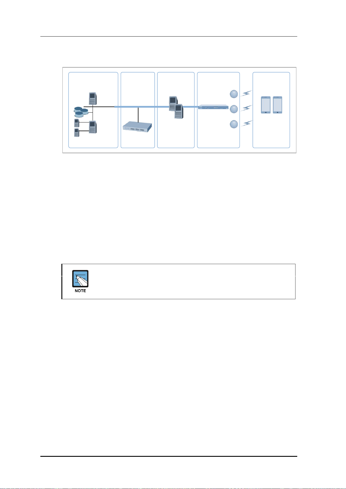
Figure 1. System Structure for Wireless Enterprise Solution
The Samsung W-EP solution, as shown in figure, comprehensively includes various
enterprise applications which are provided by wire/wireless infrastructure products and
wireless terminals. The WLAN network, a wireless infrastructure solution that provides
mobility in an enterprise environment, consists of W-EP wireless LAN Access Point (AP),
W-EP AP Controller (APC), and Wireless Enterprise WLAN Manager (WEM).
The Samsung APC and W-EP wireless LAN AP are core devices that provide various
services such as user authentication, wireless management, voice and data service, etc. in
the 802.11-based Wi-Fi environment. The WEM provides convenient configuration
environment, various statistics, and event information to an operator.
Term
In this manual, the WEC8500/WEC8050 and APC commonly represent Samsung
AP Controller. In addition, the AP means Samsung W-EP wireless LAN AP.
© SAMSUNG Electronics Co., Ltd.
page 22 of 628
Page 23
CHAPTER 1. Access Point Controller System Overview
W-EP AP
IP-PBX
WEC8050/WEC8500
WEM
Router
Internet … …
Ethernet Switch
FMC client
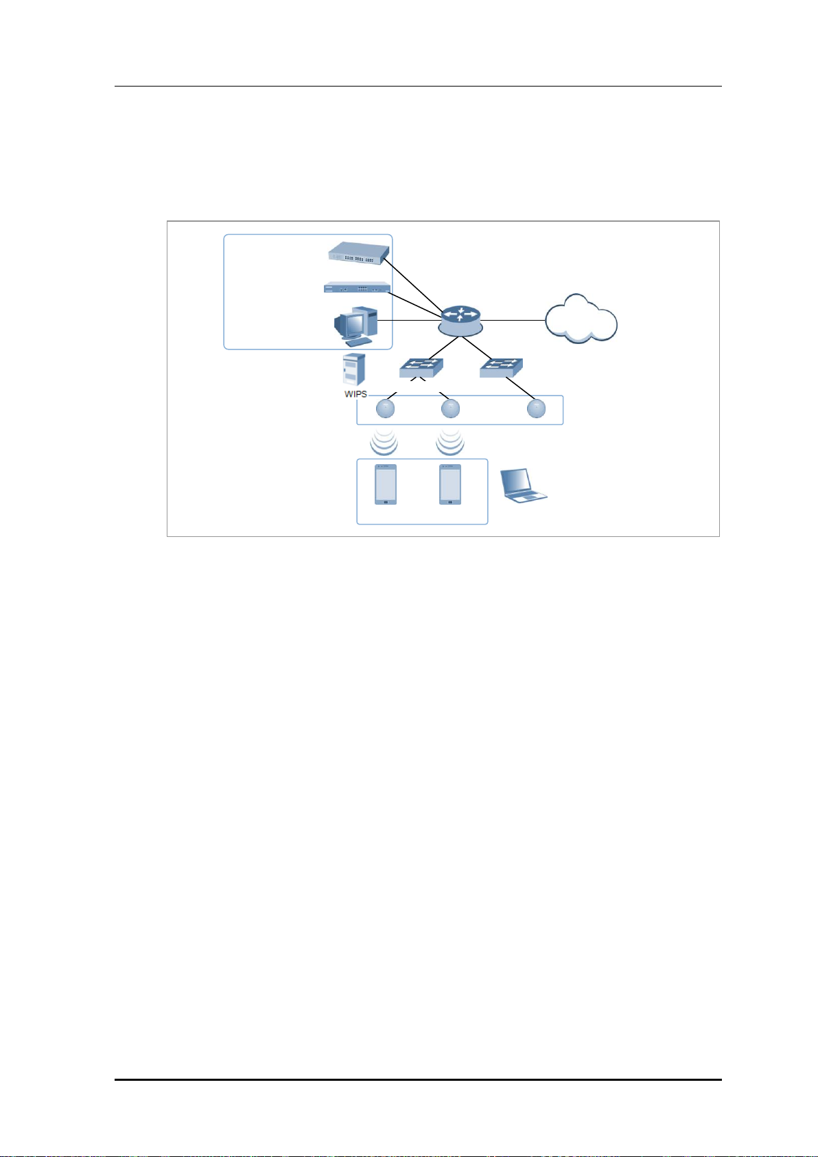
1.2 Network Configuration
The network configuration of Samsung W-EP solution that includes APC is shown below.
Figure 2. W-EP Network Configuration
IP-PBX
As an enterprise call manager, it is a switch required to provide the Fixed Mobile
Convergence (FMC) function to a wireless terminal (optional).
APC (WEC8500/WEC8050)
The APC manages all the W-EP wireless LAN APs installed in an enterprise
communication environment and it also manages user information and traffics.
Because the W-EP wireless LAN network configuration uses a centralized structure where
all the wireless user traffics are in tunneling through the APC, the APC is one of the most
important elements related to traffic management and throughput in the W-EP environment.
An APC is typically installed at a position where it can be connected to a backbone switch,
core switch or router in a network. It controls the W-EP wireless LAN AP and provides
handover, QoS, and security/authentication functions.
WEM
In the W-EP wireless LAN environment, various services are provided through a complex
network configuration. As many users are involved, its management is complex and
difficult. A normal network administrator can hardly handle any problematic issue as well
as a normal management task. The WEM is a Network Management System (NMS) that
efficiently manages this kind of W-EP wireless LAN network and service environment.
It manages a WLAN network, retrieves and configures the status of APC or W-EP wireless
LAN AP.
© SAMSUNG Electronics Co., Ltd.
page 23 of 628
Page 24

CHAPTER 1. Access Point Controller System Overview
W-EP AP (W-EP Wireless LAN AP)
The W-EP wireless LAN AP is a device that provides wireless connection service to a user
terminal. It should be installed by considering the service area or region that will be
provided in an enterprise environment. Typically, the number of W-EP wireless LAN APs
is determined by considering the size of installation area and the number of users to secure
service coverage.
Ethernet Switch
Typically, because an AP is installed in a user area, use a Power over Ethernet (PoE) switch
that does not use a power line for the beauties of environment, etc. Install the W-EP
wireless LAN APs by considering current consumption and the power capacity PoE switch.
In addition, because power drop may occur if the distance between the switch and W-EP
wireless LAN AP, the relationship between distance and power must be considered.
Typically, the distance between these two must be 100 m or less in order to avoid power
drop.
Wireless terminal/FMC Client
Terminal that provides the 802.11a/b/g/n interface such as smart phone, tablet PC, or
notebook computer, etc. In an Android smart phone, an enterprise Voice over IP (VoIP)
application equipped with the Samsung voice engine is called a FMC client (The FMC
client is an option).
Wireless additional service
In the W-EP environment, various application services are required as well as basic
wireless connection services.
The Wireless Intrusion Prevention System (WIPS) provides a security service that is one of
the most important elements in an enterprise environment. The WIPS can seamlessly
receive wireless connection service through the security services such as unauthorized
terminal, unauthorized AP, or ad hoc connection blocking, etc.
Location service that manages the location of a terminal in a wireless environment is also
an application service required in an enterprise environment. With this, it is possible to
manage the location of an effective user or an unauthorized user.
IP application service
The IP application servers required in an existing wire network including Dynamic Host
Configuration Protocol (DHCP) server, DNS server, web server, or RADIUS authentication
server are also used in the W-EP environment. Especially, the DHCP server and RADIUS
authentication server play a critical role in the wireless environment.
© SAMSUNG Electronics Co., Ltd.
page 24 of 628
Page 25

CHAPTER 1. Access Point Controller System Overview
WIPS Solution
It monitors the properness of the implementation of the wireless network infrastructure by
detecting penetration via unauthorized wireless equipment installed in the internal network,
the detoured gateway segment of the internal officers and employees who illegally connect
to the commercial WLAN service, etc. and provides the wireless network invasion
detection which implements the safe and effective wireless network environment by
detecting security vulnerabilities.
© SAMSUNG Electronics Co., Ltd.
page 25 of 628
Page 26
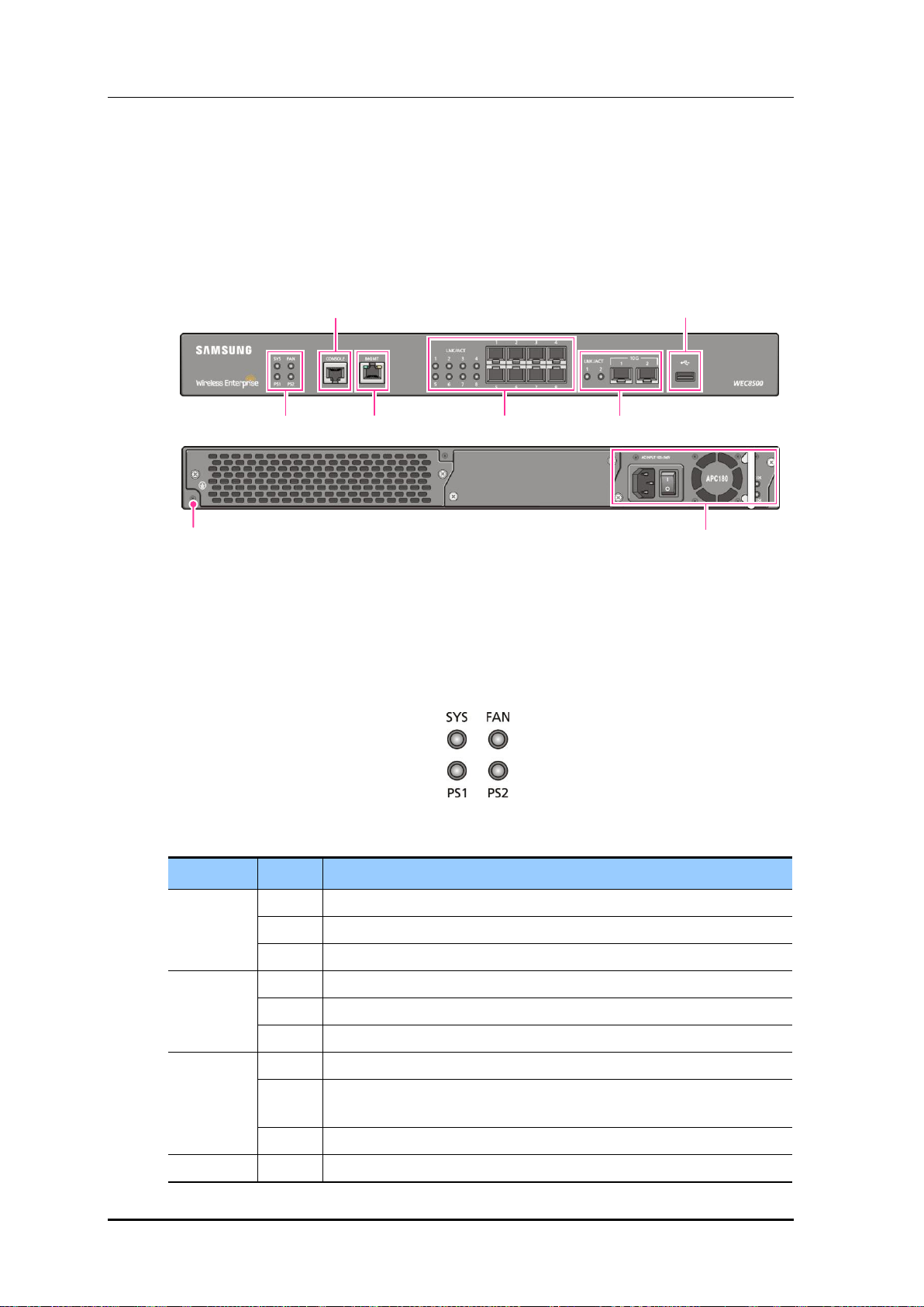
CHAPTER 1. Access Point Controller System Overview
LED
Status
Description
SYS
Green
The system is operating normally
Orange
The system is now booting
Red
Preparing the system for booting
FAN (fan
module)
Green
The installed FAN module is operating normally
Orange
The system is now booting
Red
Fan module fault has occurred
PS1 (power
module 1)
Green
Normal operation of installed power module 1
Red
Power is turned off or a fault occurred while the power module 1 is
installed.
Off
Power module 1 is not installed.
PS2 (power
Green
Normal operation of installed power module 2
Power Module
Ground hole
System LED
Console port
Management port
1G Optic port
10G Optic port
USB port
1.3 APC Configuration and Functions
1.3.1 WEC8500 Configuration and Functions
The Configuration and the purpose of each item of WEC8500 are as follows:
Figure 3. WEC8500 Interface-Front/Back
System LED
System LED indicates the various statuses of system. Each LED displays the following
information.
Figure 4. System LED Configuration
© SAMSUNG Electronics Co., Ltd.
page 26 of 628
Page 27
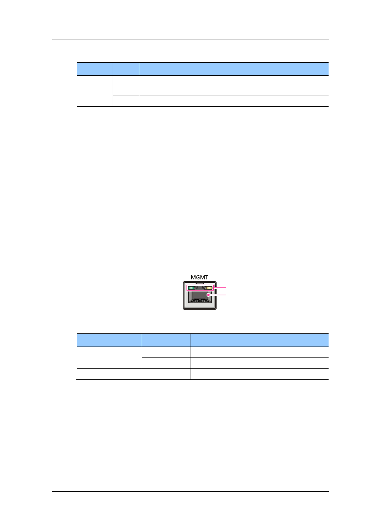
CHAPTER 1. Access Point Controller System Overview
LED
Status
Description
module 2)
Red
Power is turned off or a fault occurred while the power module 2 is
installed.
Off
Power module 2 is not installed.
Configuration item
Status
Description
LED
Green
Turned on for link connection
Orange
Blinking for data exchange
Connector
-
Connector for UTP cable connection
LED
Connector
Console port (RS232C)
A console port is used to check the operational status of WEC8500 or for input through the
CLI. Its basic requirements are as follows:
Baud rate: 115200 bps
Character size: 8 characters
Parity: None
Stop bit: 1, Data bit: 8
Flow control: None
Management port (1 GE UTP)
The WEC8500 provides a 10/100/1000BASE-T port (RJ-45) for management purpose.
It is working in 10/100 Mbps half duplex/full duplex mode or in 1000 Mbps full duplex
mode. Because it supports the automatic MDI/MDI-X function, you can use a straightthrough cable for all the network connections to a PC, server, switch, or network hub.
Figure 5. Management Port Configuration
When connecting a cable to the management port, make sure to check if the cable complies
with the 10 BASE-T, 100 BASE-TX, or 1000 BASE-T.
Cable type: UTP or STP cable using RJ-45 connector
10 BASE-T: Category 3 or higher
100 BASE-TX: Category 5 or higher
1000 BASE-T: Category 5 or higher (Category 5e or higher is recommended)
Isolate from wireless frequency disturbing waves
Shut down electrical surge
© SAMSUNG Electronics Co., Ltd.
page 27 of 628
Page 28
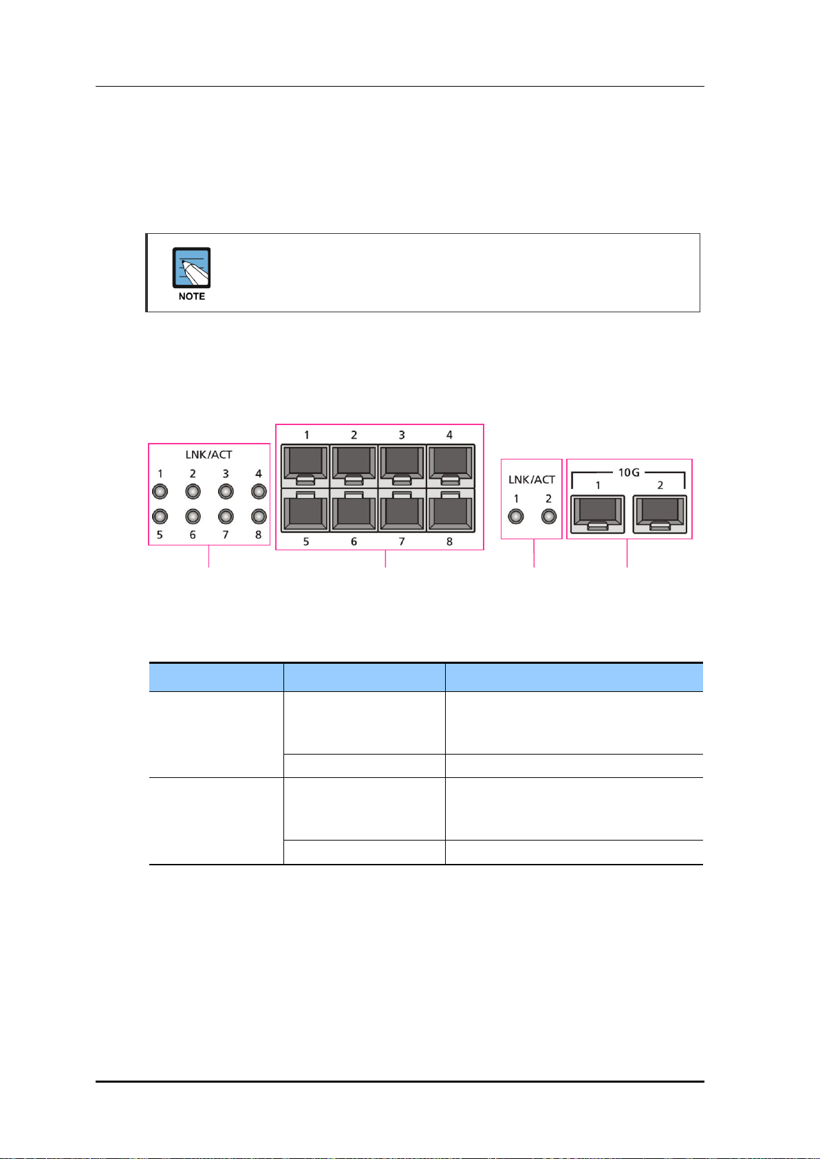
CHAPTER 1. Access Point Controller System Overview
Configuration item
Port/LED
Description
10 GE ports
LINK/ACT 1, LINK/ACT 2
LINK/ACT status of each port
- Turned on for link connection
- Blinking for data exchange
10G 1, 10G 2
10 GbE Optic module connector
1 GE port
LINK/ACT 1~LINK/ACT 8
LINK/ACT status of each port
- Turned on for link connection
- Blinking for data exchange
1G 1~1G 8
1 GbE Optic module connector
1G port
LINK/ACT LED
1G port
Connector
10G port
Connector
10G port
LINK/ACT LED
Separate the electrical wiring of a switch or related devices and the electromagnetic
area of network data line
Cable or connector and safe connection without damaged cable sheath
The 1000 BASE-T standard does not support the forced mode.
The auto-negotiation function must be always used for 1000 BASE-T port or trunk
connection.
Optic port
It provides two 10 GbE Optic ports and eight 1 GbE Optic ports and the operational status
of each port is displayed in LED.
Figure 6. Optic port configuration
USB port (Host 2.0)
The WEC8500 provides a USB host port that supports the upgrade of WEC8500 operation
software.
A typical USB memory stick is supported.
© SAMSUNG Electronics Co., Ltd.
page 28 of 628
Page 29

Power module
Configuration item
Description
Power input connector
Connector to connect the power cable to
Power switch
Switch to turn on/off power
AC LED
Turned on when there is a normal AC power input.
DC LED
Turned on when there is a normal DC power output.
Power input
connector
AC LED
Power
switch
DC LED
CHAPTER 1. Access Point Controller System Overview
Figure 7. Power module configuration
© SAMSUNG Electronics Co., Ltd.
page 29 of 628
Page 30
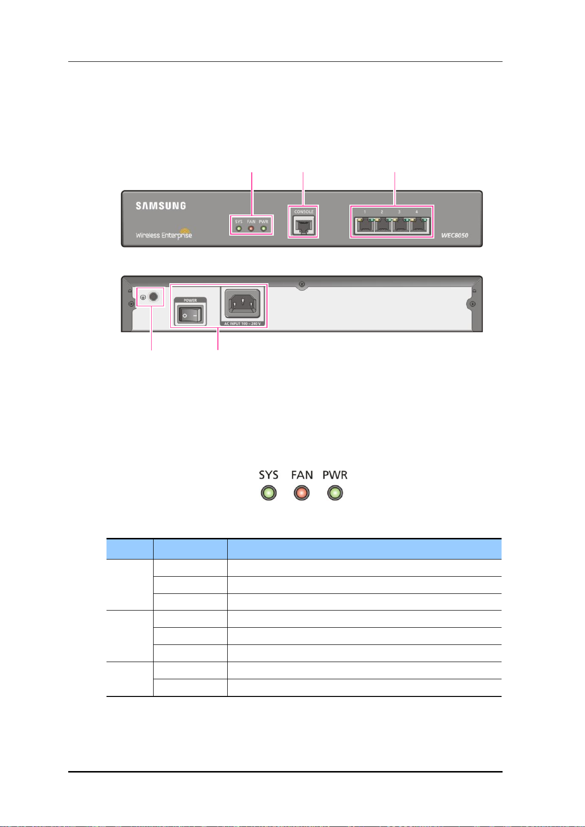
CHAPTER 1. Access Point Controller System Overview
LED
Status
Description
SYS
Green
The system is operating normally
Orange
The system is now booting
Red
Preparing the system for booting
FAN
Green
The installed FAN module is operating normally
Orange
The system is now booting
Red
Fan fault
PWR
Green
The power is supplied normally
Off
The power is turned off or not supplied
Status LED
Console Port
Ethernet Port
Ground hole
Power
1.3.2 WEC8050 Configuration and Functions
The configuration and the purpose of each item of WEC8050 are as follows:
Figure 8. WEC8050 interface-Front/Back
Status LED
This LED indicates the various statuses of system. Each LED displays the following
information.
Figure 9. Status LED configuration
© SAMSUNG Electronics Co., Ltd.
page 30 of 628
Page 31

CHAPTER 1. Access Point Controller System Overview
LED
Status
Description
ACT
Orange blinking
Blinking while data exchanging
Off
No data exchanging
LINK
Green
Link connection display
Off
No link connection
LINK LED
ACT LED
Console port (RS232C)
A console port is provided to check the operational status of WEC8050 or for input through
the CLI.
Its basic requirements are as follows:
Default baud rate: 115200 bps
Character size: 8 Characters
Parity: None
Stop bit: 1, Data bit: 8
Flow control: None
Ethernet port
It has 4 10/100/1000 Base-T ports.
Figure 10. Ethernet Port Configurations
© SAMSUNG Electronics Co., Ltd.
page 31 of 628
Page 32

CHAPTER 1. Access Point Controller System Overview
PRI
Firewall
Internet
Backbone
switch
SBC
PSTN
IP-PBX
Media G/W
APC
WIPS
Loc
server
WEM
AAA
server
DHCP
W-EP AP
PoE switch
Access switch
PoE switch
Access switch
W-EP AP
1.4 APC Application Configuration and Service
Scenario
1.4.1 Basic Configuration
To provide wireless connection service using a wireless LAN in the W-EP environment, the
W-EP wireless LAN AP that helps a terminal connect to the network through wireless and
an APC that controls the terminal are basically required. Especially, the role of APC is
critical to guarantee QoS of various services and provide high level of security functions in
an Enterprise communication environment. As various elements are required in the W-EP
environment, it is necessary to intuitively or organically manage each element via WEM.
In addition, the IP application servers including authentication server, DHCP server, or
DNS server which is a basic network configuration element in a wire enterprise
environment are also interoperated to provide more convenient and various mobile services
to users. One outstanding example is the FMC service that provides enterprise level VoIP in
a wireless LAN. With this, the wire/wireless integrated voice service can be provided.
An example of service configuration diagram using the W-EP wireless LAN system is
shown in the below figure. The configuration diagram is based on Samsung APC
(WEC8500).
Figure 11. Basic Configuration of W-EP Wireless LAN System
© SAMSUNG Electronics Co., Ltd.
page 32 of 628
Page 33

CHAPTER 1. Access Point Controller System Overview
PRI
Firewall
Internet
Backbone
switch
SBC
PSTN
IP-PBX
Media G/W
APC
WIPS
Loc
server
WEM
AAA
server
DHCP
PoE switch
Access switch
PoE switch
Access switch
IP-PBX
W-EP AP
W-EP AP
The basic W-EP wireless LAN network configuration is a centralized structure where all
the wireless user traffics go through tunneling between APC and W-EP wireless LAN AP.
Therefore, the network information such as subnet information allocated to a wireless user
depends on the configuration of backbone network where the APC is connected.
This provides the following advantages during network configuration and setup.
Installing the APC is just adding it to a legacy data center or backbone network.
Therefore, the possibility of physical change of core network can be reduced.
In addition, separate design of wire/wireless network is easy using the APC as a
boundary.
No dramatic network change is required to install the W-EP wireless LAN AP.
An AP installed in a user area is located in various local network environments in a wide
region. Although it is unavoidable to install or expand a PoE switch, the modification of
local network where wire users are already configured can be minimized.
Because the APC relays all the user traffics, it can restrict a wireless attacker’s effects
and provide differentiated service for each user.
1.4.2 Configuration of Multiple APC for Redundancy
The APC provides the redundancy function to guarantee QoS for various services and
provide service stability in the W-EP environment.
An example of service configuration diagram for redundancy is shown in the below figure.
Figure 12. Example of W-EP Wireless LAN System Configuration for Redundancy
© SAMSUNG Electronics Co., Ltd.
page 33 of 628
Page 34

CHAPTER 1. Access Point Controller System Overview
In this configuration, several APC s are used to minimize service disruption caused by a
disconnected APC and to enhance service sustainability. Basically, two or more APC s
must be installed in the same site for APC redundancy. The redundancy configuration
includes active-active configuration, active-standby configuration, and many-to-one
configuration. An operator can select a configuration based on the number of available
APC s and redundancy level.
1.4.3 Clustering Configuration using Multiple APC (WEC8500)
The W-EP environment has various area sizes, user density and number of users. If only a
single APC is required for service and management, the complexity of network
configuration or management is not high. However, if the capacity of a single APC is not
sufficient, multiple APC s must be installed for service. The WEC8500 is a Samsung APC
model providing the clustering environment.
To set up a wireless LAN network in an environment where multiple WEC8500s are
installed, the integrated management system and user service must be provided through
clustering configuration between the WEC8500s. This allows inter APC handover.
The WEC8500s configured in a cluster provides a service just like a single WEC8500
through periodic information exchange.
Inter APC handover
The inter APC handover is a handover between APCs. A clustering group is used
to provide this function and this clustering group means a virtual area.
Maximum 12 WEC8500s can be bound to a single group. An APC in a group
cannot be added to another group.
It provides layer 3 handover and the handover is supported when a terminal
moves to an APC which have different subnets. A serving APC is called as an
anchor APC and a target APC is called as a foreign APC. The control path and
also the tunnel for data traffic between APCs provide security using IPSec.
The inter APC handover provides this function both in the standard Wi-Fi
handover and Samsung’s unique AirMove method.
© SAMSUNG Electronics Co., Ltd.
page 34 of 628
Page 35

CHAPTER 1. Access Point Controller System Overview
PRI
Firewall
Internet
Backbone
switch
SBC
PSTN
IP-PBX
Media G/W
Loc
server
WEM
AAA
server
DHCP
PoE switch
Access switch
PoE switch
Access switch
IP-PBX
WEC8500
(building-2)
APC Clustering
W-EP AP
W-EP AP
WEC8500
(building-1)
1.4.3.1 Configuration of Distributed Clustering Service
The configuration of distributed clustering is to install each WEC8500 in a building or a
local site according to its capacity. This option can be used when there is no integrated
backbone configuration in a site or networks are separated for each building. It is suitable
for a site where several buildings are apart from each other.
An example of service configuration diagram is shown in the below figure.
Figure 13. Example of W-EP Wireless LAN System Configuration for Distributed Clustering Service
© SAMSUNG Electronics Co., Ltd.
page 35 of 628
Page 36

CHAPTER 1. Access Point Controller System Overview
WEM
AAA
server
DHCP
PRI
Firewall
Internet
Backbone
switch
SBC
PSTN
IP-PBX
Media G/W
PoE switch
Access switch
PoE switch
Access switch
IP-PBX
APC Clustering
Loc
server
Building-1
Building-2
W-EP AP
W-EP AP
WEC8500
(building-1)
WEC8500
(building-2)
1.4.3.2 Configuration of Centralized Clustering Service
In the centralized cluster configuration, all the WEC8500s in a site are installed in the
center. This is suitable when all the networks in a site are configured around the backbone.
This option is suitable for a site where several buildings are close to each other or a large
building where a seamless handover service is required using one or more WEC8500s.
Better performance can be obtained if there is a single backbone network and it is
preferable in terms of installation or maintenance because its service configuration is
simple.
An example of service configuration diagram is shown in the below figure.
Figure 14. Example of W-EP Wireless LAN System Configuration for Centralized Clustering Service
© SAMSUNG Electronics Co., Ltd.
page 36 of 628
Page 37

CHAPTER 1. Access Point Controller System Overview
PRI
Firewall
Internet
Backbone
switch
SBC
PSTN
IP-PBX
Media G/W
APC
WIPS
Loc
Server
WEM
AAA
server
DHCP
Router
Branch
PoE switch
W-EP AP
HQ
PoE switch
Access switch
PoE switch
Access switch
W-EP AP
W-EP AP
1.4.4 Configuration of Multiple Sites Consisting of Headquarter
and Branches
The W-EP wireless LAN network environment usually consists of one headquarter and
several branches.
In this case, there are two types of network configuration.
Hierarchical type: A APC is installed in a branch as well as headquarter.
Branch AP type: A APC is installed only in a headquarter and only a W-EP wireless
LAN AP is installed in a branch.
In the hierarchical type, it is advantageous that each branch can use each different service
policy. However, the management in headquarter is complex and many low-capacity APCs
must be installed, so the branch AP type is commonly used.
The branch AP type has the same structure as a basic W-EP wireless LAN configuration.
A single difference is that a W-EP wireless LAN AP installed in a branch is located at a
remote place. The APC in headquarter provides a wireless LAN service in the headquarter
building and also provides a wireless LAN service to a remote W-EP wireless LAN AP
installed in a branch. As the APC in headquarter manages all the W-EP wireless LAN APs
using the same policy, it is easy to use and cost-effective.
An example of service configuration diagram for the branch AP type is shown in the below
figure.
Figure 15. Example of W-EP Wireless LAN System Configuration for Multiple Sites consisting of
© SAMSUNG Electronics Co., Ltd.
Headquarter and Branches
page 37 of 628
Page 38

CHAPTER 1. Access Point Controller System Overview
If user traffics are concentrated on a single centralized APC when there are many branches
or they are far from headquarter, performance may be deteriorated due to the time delay of
packet transmission, etc. Therefore, use different operation schemes according to the
location of W-EP wireless LAN AP in the configuration of headquarter and branches.
In other words, the local W-EP wireless LAN AP in a headquarter does traffic tunneling to
an APC and the branch AP installed in a branch switches a user traffic directly to a
destination address without tunneling to the APC. Even at this time, the APC in
headquarter manages all the W-EP wireless LAN APs and users.
© SAMSUNG Electronics Co., Ltd.
page 38 of 628
Page 39

CHAPTER 1. Access Point Controller System Overview
Service
TCP Port
UDP Port
Description
General
20, 21
-
FTP Server
22 - Secure Shell
23 - Telnet
80, 443
-
HTTP Web Server
123
123
NTP
AP-APC
Connection
-
5246, 5247
CAPWAP
IP-PBX
WEC8050/
WEC8500
WEM
Router
Internet
…
…
FMC Client
Router
…
…
FMC Client
W-EP AP
W-EP AP
1.5 NAT Configuration between AP and APC
The APC system provides the same services even when the APC or AP is in a NAT
environment.
If the APC system is in a NAT environment and obtaining a public IP address is difficult,
the APC can be configured to use a private IP address by enabling port mapping on the
existing NAT equipment, so that it can provide services to APs on the public IP network
and APs existing under other NAT networks.
Using this feature requires that the NAT equipment be applied with the following port
settings:
An example of service configuration diagram for the NAT environment is illustrated below.
Figure 16. AP-APC NAT Environment Configuration Diagram
© SAMSUNG Electronics Co., Ltd.
page 39 of 628
Page 40

CHAPTER 2. Basic System Configuration
CHAPTER 2. Basic System
Configuration
In this chapter, the basic system configuration using web and Command Line Interface
(CLI) is introduced and how to use CLI and Web UI is described.
2.1 Basic System Configuration
2.1.1 CLI Connection
Connecting to APC using CLI is as follows:
Direct connection to the system console port
Telnet or SSH connection through an Ethernet port
When the booting of APC is completed, log into the system as follows:
1) For the first connection, log in using ID: ‘samsung’ and Password: ‘samsung’.
USERNAME : samsung
PASSWORD : samsung
THIS IS YOUR FIRST LOGIN AFTER USER ACCOUNT HAS BEEN CREATED.
YOU MUST CHANGE YOUR PASSWORD.
ENTER LOGIN PASSWORD : samsung
ENTER NEW PASSWORD : ********
CONFIRM NEW PASSWORD : ********
PASSWORD SUCCESSFULLY CHANGED
WEC8500 #
2) After the first login, you must change the password. Use the changed password for the
next login.
The default ID of APC is set to ‘samsung’ that has an administrator privilege.
© SAMSUNG Electronics Co., Ltd.
page 40 of 628
Page 41

2.1.2 Managing Operator Account
Parameter
Description
USERNAME
User ID
USERLEVEL
User level
DESCRIPTION
Adds user information
An operator who has an administrator privilege (level 1) can create or delete a new operator
account. When creating an account, specify the account’s privilege level (level 1-4).
To set up operator account related functions, go to configure mode by executing the
following command.
WEC8500# configure terminal
WEC8500/configure #
Adding or deleting an account
The commands used to create or delete an account are as follows:
mgmt-user [USERNAME] [USERLEVEL] description [DESCRIPTION]: Adds a user
no mgmt-user [USERNAME]: Deletes a user
CHAPTER 2. Basic System Configuration
WEC8050/configure# mgmt-user test 1 description “test account”
PASSWORD : *********
CONFIRM PASSWORD : *********
USER(test) CREATED.
WEC8050/configure# no mgmt-user test
user(test) deleted.
Retrieving account information
To check user account information use the ‘show mgmt-users’ command.
Changing Password
Use the ‘password’ command to change the password for your account.
The ‘password’ command must be executed in the highest user mode.
WEC8500# password
CURRENT PASSWORD : ********
NEW PASSWORD : ********
CONFIRM NEW PASSWORD : ********
© SAMSUNG Electronics Co., Ltd.
page 41 of 628
Page 42

CHAPTER 2. Basic System Configuration
Category
Description
?
Displays the command list and help at the current level
Command ?
Displays the parameter and help required for a command
2.1.3 APC Management Port Configuration
To connect to the APC remotely using telnet/SSH or web, it is necessary to set up an IP
address to the management port.
Set up the management port as follows:
1) Go to configure ‘mgmt0’ interface configuration mode of CLI.
WEC8500# configure terminal
WEC8500/configure# interface mgmt0
2) Set up an IP address.
WEC8500/configure/interface mgmt0# ip address 100.100.100.1/24
In case of WEC8050, there is no management (mgmt0) port. After establishing an
IP address in one of ports ge1 to ge4 by referring to the contents of 'Port
Configuration' and then using the CLI, connect the Ethernet cable to the port.
2.1.4 SNMP Community Configuration
To connect to the web server of APC, it is necessary to add Simple Network Management
Protocol (SNMP) community through CLI. For more information, see ‘10.1 SNMP
Configuration’.
2.1.5 CLI Basic Usage
The CLI is a text command based interface used to change or retrieve the system settings.
Several users can change the settings at the same time using the CLI of the same system.
Because privilege per user is already configured, a user can execute a command allowed by
the user’s privilege. Various commands are available for each system function. For more
information, see ANNEX ‘CLI Command Structure’.
Command Help
The CLI provides a help for all the commands. To see a help for a command and parameter,
enter ‘?’. Based on an input character, it shows a help for a command or parameter that can
be entered.
© SAMSUNG Electronics Co., Ltd.
page 42 of 628
Page 43

CHAPTER 2. Basic System Configuration
A usage example is given below.
WEC8500# show ?
80211a Display 802.11a network settings
80211bg Display 802.11bg network settings
80211h Display 802.11h configuration
access-list List IP access lists
alarm Show alarm information
ap Show ap information
ap-debug Show ap debug information
...
vap Show vap information
version Show package version information
vlan Display VLAN information
vqm Show vqm command
vrrp VRRP information
wids Wids command
wips Wips command
wireless-acl-list Show wireless-acl-list
wlan Show wlan information
WEC8500#
Command automatic completion function
The CLI supports the command automatic completion function using the TAB key.
When you press the TAB key after entering the first few characters of a command, the rest
characters of the command that starts with the entered characters is automatically entered.
If there are several commands that start with the entered characters, press the TAB key to
jump to the next command. The below example shows the ‘show’, ‘save’, or ‘ssh’
command is entered in order by entering ‘s’ and pressing the TAB key.
WEC8500# s
[When the TAB key is pressed]
WEC8500# show
[When the TAB key is pressed once again]
WEC8500# save
© SAMSUNG Electronics Co., Ltd.
page 43 of 628
Page 44

CHAPTER 2. Basic System Configuration
Command error
When a command that is not supported by the system is entered, an error message is
displayed.
WEC8500# command-unknown
^
Error : Command ‘command-unknown’ does not exist
When a parameter that is not supported by a command is entered, an error message
according to the situation is displayed.
WEC8500# configure test
^
% Invalid parameter (mandatory)
Command modes
When the ‘exit’ command is entered, the mode is changed to the upper command mode.
© SAMSUNG Electronics Co., Ltd.
page 44 of 628
Page 45

2.2 Using Web UI
2.2.1 Web UI Connection
To use the WEC, i.e. Web UI of APC system, the IP address of ethernet port must be set up.
When connecting to the IP address of APC ethernet port in a web browser, the below login
window is displayed. Log in using a default connection account ‘samsung’.
After the first login, you go through the course of changing the password. If you have
changed the password by connecting to the CLI, you don't have to go through the course of
changing the password.
CHAPTER 2. Basic System Configuration
© SAMSUNG Electronics Co., Ltd.
Figure 17. Web UI Connection Window
page 45 of 628
Page 46

2.2.2 WEC Main Window
Sub-menu
Menu bar
The WEC Main window consists of menu bar, sub-menus, and detail windows of each
menu.
CHAPTER 2. Basic System Configuration
Figure 18. WEC Main Window
Menu bar
The menu bar consists of the following items:
: Provides detail configuration or retrieval function for each item. When you select
each item, lower menus in the sub-menus area are displayed.
: Displays a user login ID.
: Logs out from the WEC.
: Saves the current configuration information into the system.
: Refreshes the screen.
Sub-menus
This provides the detail menus for Monitor, Configuration, Administration, or Help in the
menu bar.
© SAMSUNG Electronics Co., Ltd.
page 46 of 628
Page 47

2.2.3 Managing Operator Account
To add a operator account in Web UI, follow the below procedure.
In the menu bar of <WEC Main window>, select <Administration> and then select
<Local Management Users> menu in the sub menu. The subtree shows the <APC> and
<AP> menu items. Select <APC>.
You can add or delete a operator account in the WEC.
Figure 19. Operator Account Management Window
1) To add an account, click the <Add> button.
CHAPTER 2. Basic System Configuration
Figure 20. Operator Account Addition Window
2) Enter an item according to each parameter description, and click the <Apply> button.
ID: Username to add
PASSWORD: User’s initial password
CONFIRM PASSWORD: Re-enter the initial password
LEVEL: User privilege
1 (Administrator): Administrator privilege that allows to execute all the
commands
2 (Operator): Can change system configuration.
3 (Monitor): Can retrieve system status.
4 (Lobby Ambassador): Temporary user
© SAMSUNG Electronics Co., Ltd.
page 47 of 628
Page 48

2.3 Initial Setup Wizard
2.3.1 Overview
The initial setup wizard aims to finish the basic settings by guiding the settings required for
the basic WLAN service in order when the APC is installed. It supports only the basic
settings to operate the WLAN service and the settings which are additional or are not
frequently used are not supported here. They must be made through the general WEC
screen.
2.3.2 Connecting
Connecting condition
If being connected to the WEC as web UI at the factory reset state or while there is no
WLAN, the APC system is connected to the Initial Setup Wizard instead of the general
WEC screen.
CHAPTER 2. Basic System Configuration
Connecting at the factory reset state
The connection at the factory reset state is available through the management port.
1) Connect the Ethernet cable to the management port and then to the PC.
2) The default IP address of the management port is 192.168.1.2. After configuring the IP
address of the PC fit for the bandwidth, open the web browser.
3) Enter 192.168.1.2 in the address bar of the browser to access.
In case of WEC8050, there is no management (mgmt0) port. After establishing
the IP address in one of ports ge1 to ge4 by using the CLI first on reference to
‘3.1 Port Configuration’, connect the Ethernet cable to the port.
Access while the IP address is set
If the IP address of the APC is set, check whether the APC and the PC are networked and
then open the web browser before accessing the IP address.
© SAMSUNG Electronics Co., Ltd.
page 48 of 628
Page 49

2.3.3 How to Use
If the access to the APC is made through the web browser, follow the login procedure as
shown in ‘2.2.1 Web UI Connection’. After that, you can see the Welcome message by
connecting to the wizard.
CHAPTER 2. Basic System Configuration
Figure 21. Initial Setup Wizard Welcome Screen
Press the Next button to move to the configuration step 1 and then start the basic settings.
Press the Exit button to close the wizard and then move to the general WEC screen.
Start the wizard and then deactivate all wireless communications of the APC system as well
as the function of automatically registering the AP. The settings are recovered at the last
step of the wizard.
Description on the Screen
Figure 22. Move to the setup step of the initial setup wizard
© SAMSUNG Electronics Co., Ltd.
page 49 of 628
Page 50

CHAPTER 2. Basic System Configuration
: Show the current setup step and the whole setup step by being located on the top of the
screen. When you hover the mouse over each number, it shows the name of the step and
you can click to move to the step just before or after the current step.
: When you press the Next button, you move to the next setup step and when you press
the Prev button, you return to the previous setup step.
: Press the Exit button to close the wizard and then move to the general WEC screen. In
the case, you cannot return back to the initial setup wizard screen. If the APC restarts
while the WLAN is not created, you can go to the wizard screen again.
Setup Step
The initial setup wizard consists of the following setup steps: After setting up the
description desired on each screen, click the Apply button to apply the modifications to the
system.
1) General setup:
Set up basic information including the name, location, contact number, etc. of the
system.
Set up the basic country code and the basic environment.
Set up the system time and the time zone. Click the PC TIME button to change the
time of the APC by setting to the time of the PC.
2) Interfaces:
Create interfaces. For more information, refer to '3.2.1 Interface Management' and
‘3.3.1 VLAN’.
3) Interface groups:
Create interface groups and assign the interfaces created at the previous step.
For more information, refer to ‘3.2.2 Managing Interface Group’
4) Default Gateway:
Set up a default gateway of the system. The default gateway is a default path to be
used when the APC communicates with another equipment on the TCP/IP network.
5) WLAN:
Create a WLAN. For more information, refer to ‘5. WLAN Management’.
If the L2 Security Type corresponds to one of the following conditions, move to the
step of setting up a RADIUS server. For more information on creating a RADIUS
server, refer to ‘8.1.1 External RADIUS Server’.
(1) 802.1x
(2) Static WEP + 802.1x
(3) +WPA2 and enabled 802.1x
6) DHCP proxy:
When an external DHCP server is used, configure settings of proxy or relay.
7) DHCP internal server:
Configure a DHCP internal server. For more information, refer to ‘5.4.1 DHCP
Server’.
© SAMSUNG Electronics Co., Ltd.
page 50 of 628
Page 51

CHAPTER 2. Basic System Configuration
8) DNS:
The APC gets DNS information from a DNS server and provides the DNS relay
function that relays the DNS server and a client. If a DNS server is connected to the
APC and a UE connected to the APC configures the DNS server as the APC, the
DNS service can be received.
9) NTP:
If the APC is configured as a NTP client, it receives the Coordinated Universal
Time (UTC) information from the configured NTP server and synchronizes the
local time.
10) Finish:
Finish the basic settings to configure the WLAN of the APC and then close the
wizard.
© SAMSUNG Electronics Co., Ltd.
page 51 of 628
Page 52

CHAPTER 3. Data Network Function
CHAPTER 3. Data Network Function
In this chapter, how to set up the data network functions of APC including VLAN, link
aggregation, and layer 3 protocol is described.
3.1 Port Configuration
The APC port is configured with a physical interface.
Physical interface of 11 ports except WEC8500 console port
Physical interface of 4 ports except WEC8050 console port
3.1.1 Port management
The WEC8500 Management port is used to manage the WEC8500. It does not
support VLAN and its interface name is ‘mgmt0’. The 8 ports at the right side of
Management port are 10/100/1000 BASE T-ports and their names are GE1-8.
To the right side of the 10/100/1000 BASE T-ports, there are two Gigabit ports, i.e.
XE1 and XE2. In case of WEC8050, there is no management (mgmt0) port. After
establishing the IP address in one of ports ge1 to ge4 by using the CLI first,
connect the Ethernet cable to the port.
Configuration using CLI
To configure the port related function, enter into the interface mode by entering the
‘interface [INTERFACE_NAME]’ command in the configure mode.
An example of entering into the interface setup mode of the management port is shown
below.
WEC8500# configure terminal
WEC8500/configure# interface mgmt0
WEC8500/configure/interface mgmt0#
© SAMSUNG Electronics Co., Ltd.
page 52 of 628
Page 53

CHAPTER 3. Data Network Function
The port related CLI commands are as follows:
[auto-nego, speed, duplex]
The commands used to configure an auto-nego, speed, and duplex addresses are shown
below. To delete the configuration, enter the ‘no’ parameter.
WEC8500/configure/interface ge1# speed-duplex ?
10-full Set 10Mb/s full-duplex
10-half Set 10Mb/s half-duplex
100-full Set 100Mb/s full-duplex
100-half Set 100Mb/s half-duplex
1000-full Set 1000Mb/s full-duplex
1000-half Set 1000Mb/s half-duplex
auto-nego Set auto negotiation speed/duplex
[admin status]
This is a command that makes the port not working. The ‘no’ parameter is used to restart
the port.
shutduown
no shutdown
[flow control]
This is a command that operates flow control to the port. The ‘no’ parameter is used to stop
the flow control.
flowcontrol on
no flowcontrol on
[switch port]
This is a command that changes the port to the L2 mode. The ‘no’ parameter is used to
change it to the L3 mode.
switchport
no switchport
[ip address]
This is a command that configures a static IP address. To delete the configuration, enter the
‘no’ parameter.
ip address {A.B.C.D/mask length}
no ip address {A.B.C.D} {A.B.C.D}
no ip address {A.B.C.D/mask length}
© SAMSUNG Electronics Co., Ltd.
page 53 of 628
Page 54

CHAPTER 3. Data Network Function
Below is an example of port setting to enter the initial setup wizard upon the initial
installation of WEC8050.
WEC8500/configure/interface ge1# no shutdown
WEC8500/configure/interface ge1# flowcontrol on
WEC8500/configure/interface ge1# no switchport
WEC8500/configure/interface ge1# ip address 192.168.1.2/24
Configuration using Web UI
In the menu bar of <WEC Main window>, select <Configuration> and then select the
<Controller> <Ports> menu in the sub-menus. Operator can configure the ports.
The Ports initial window is shown below.
Operator can check the current status of each port.
Figure 23. Port Management Window
The auto-nego, speed, or duplex can be configured only when the cable type is
Copper.
They cannot be configured if the cable type is Optic (The auto-nego should
always be enabled whether the cable type is copper or optic).
© SAMSUNG Electronics Co., Ltd.
page 54 of 628
Page 55

CHAPTER 3. Data Network Function
[Port Configuration Change]
1) In the Ports initial window, click the <INTERFACE NAME> button to go to port
configuration change window.
2) In the port configuration change window, the auto-nego, speed, duplex, admin status,
flow control, mtu size, switch port, or ip address, etc. can be configured.
Figure 24. Port Configuration Change Window
© SAMSUNG Electronics Co., Ltd.
page 55 of 628
Page 56

3.2 Interface Configuration
The WEC8500 interface consists of the following physical interface and virtual interface.
Physical interface of 11 ports except console port
1024 virtual interfaces using VLAN
There are two types of WEC8050 interface as shown below; physical interface and virtual
interface.
Physical interface of 4 ports except console port
128 virtual interfaces using VLAN
3.2.1 Interface management
The WEC8500 Management port is used to manage the WEC8500. It does not
support VLAN and its interface name is ‘mgmt0’. The 8 ports at the right side of
Management port are 10/100/1000 BASE T-ports and their names are GE1-8.
To the right side of the 10/100/1000 BASE T-ports, there are two Gigabit ports, i.e.
XE1 and XE2.
CHAPTER 3. Data Network Function
Configuration using CLI
To configure the interface related function, go to the interface mode by entering the
‘interface [INTERFACE_NAME]’ command in the configure mode. An example of
entering into the interface mode of the management port is shown below.
WEC8500# configure terminal
WEC8500/configure# interface mgmt0
WEC8500/configure/interface mgmt0#
The interface related CLI commands are as follows:
[ip address]
This is a command that configures a static IP address. The ‘no’ parameter is used to delete
the configuration.
ip address {A.B.C.D/mask length}
no ip address {A.B.C.D} {A.B.C.D}
no ip address {A.B.C.D/mask length}
© SAMSUNG Electronics Co., Ltd.
page 56 of 628
Page 57

CHAPTER 3. Data Network Function
[ip address dhcp]
This is a command that configures a dynamic IP address using DHCP. The ‘no’ parameter
is used to delete the configuration.
ip address dhcp
no ip address dhcp
[shutdown]
This is a command that makes the interface not working. The ‘no’ parameter is used to
restart the interface.
shutdown
no shutdown
Configuration using Web UI
In the menu bar of <WEC Main window>, select <Configuration> and then select the
<Controller> <Interfaces> menu in the sub-menus. You can configure an interface and
VLAN.
The Interface initial window is shown below.
Figure 25. Interfaces Window (1)
[Adding VLAN]
1) In the Interface initial window, click the <Add> button to go to VLAN creation
window.
2) Enter an INTERFACE NAME and VLAN ID in the VLAN creation window.
The INTERFACE NAME describes a VLAN to create and English characters without
a space, numbers, and ‘_’ can be used. The VLAN ID is the number from 1 to 4094
and it specifies a unique VLAN value.
Click the <Apply> button to go to detail configuration screen.
Figure 26. Interfaces Window (2)
© SAMSUNG Electronics Co., Ltd.
page 57 of 628
Page 58

CHAPTER 3. Data Network Function
3) Perform detail configuration in the VLAN detail configuration window.
If you specify PRIMARY DHCP SERVER or SECONDARY DHCP SERVER in the
DHCP area, you can specify the configuration of a DHCP server.
After configuration, click the <Apply> button to apply it to the system.
[Deleting VLAN]
In the Interface initial window, click the <Delete> button to delete a selected VLAN.
The select VLAN cannot be deleted if it is being used in the system.
© SAMSUNG Electronics Co., Ltd.
Figure 27. Interfaces Window (3)
page 58 of 628
Page 59

3.2.2 Managing Interface Group
To use WLAN and other services, it is necessary to configure an interface into an interface
group.
Configuration using CLI
An example of entering into the group configuration mode of ifg_01 interface is shown
below.
WEC8500# configure terminal
WEC8500/configure# if-group ifg_01
Interface Group related commands are as follows:
[Creating or Deleting Interface group]
This command creates an interface group. Use ‘no’ parameter to delete an interface group.
CHAPTER 3. Data Network Function
if-group [INTERFACE_GROUP_NAME]
no if-group [INTERFACE_GROUP_NAME]
[Adding or deleting Interface]
This command adds an interface to an interface group being configured. Use ‘no’
parameter to delete an interface.
add-if[INTERFACE_IP_ADDRESS]
no add-if[INTERFACE_ IP_ADDRESS]
[Retrieving Interface Group Status]
This command retrieves the configuration status of an interface group.
show if-group
Configuration using Web UI
In the menu bar of <WEC Main window>, select <Configuration> and then select the
<Controller> <Interfaces Groups> menu in the sub-menus. Click the <Add> or
<Delete> button to add or delete an interface group.
© SAMSUNG Electronics Co., Ltd.
Figure 28. Interface Group Window (1)
page 59 of 628
Page 60

CHAPTER 3. Data Network Function
Follow the below procedure to add an interface group.
1) In the Interface group initial window, click the <Add> button.
2) Enter information on GROUP NAME and GROUP DESCRIPTION and then add or
delete an interface to or from an interface group.
Figure 29. Interface Group Window (2)
3) Click the <Apply> button to apply the configuration.
© SAMSUNG Electronics Co., Ltd.
page 60 of 628
Page 61

3.3 VLAN Configuration
3.3.1 VLAN
Configuration using CLI
To configure VLAN, go to the VLAN interface mode by executing the following command.
WEC8500# configure terminal
WEC8500/configure# interface vlan
WEC8500/configure/interface vlan#
The related command is shown below and the range of VLAN ID is 1-4094.
[vlan bridge]
This command creates VLAN. The ‘no’ parameter is used to delete VLAN.
CHAPTER 3. Data Network Function
vlan [VLAN_ID] bridge 1
no vlan [VLAN_ID] bridge 1
[switchport access vlan]
This command set the VLAN mode to the access or hybrid mode. The ‘no’ parameter is
used to delete the VLAN configuration.
switchport {access/hybrid} vlan [VLAN_ID]
[switchport mode]
This command configures the mode of switch port. The ‘no’ parameter is used to delete the
configuration.
switchport mode {access/hybrid/trunk}
no switchport mode
[switchport hybrid allowed vlan]
This command configures the mode of switch port to hybrid. The ‘no’ parameter is used to
delete the configuration.
switchport hybrid allowed vlan: Configures VLAN to hybrid.
switchport hybrid allowed vlan all: Configures all the allowed VLANs to hybrid.
switchport hybrid allowed vlan none: Stops VLAN data transmission/reception.
switchport hybrid allowed vlan add [VLAN_ID]: Adds VLAN to the hybrid mode.
switchport hybrid allowed vlan remove [VLAN_ID]: Deletes VLAN from the hybrid
mode.
no switchport hybrid vlan: Deletes all the hybrid settings.
© SAMSUNG Electronics Co., Ltd.
page 61 of 628
Page 62

CHAPTER 3. Data Network Function
[switchport trunk allowed vlan]
This command configures the mode of switch port to trunk. The ‘no’ parameter is used to
delete the configuration.
switchport trunk allowed vlan: Configure VLAN to the trunk mode.
switchport trunk allowed vlan all: Configure all the VLANs to the trunk mode.
switchport trunk allowed vlan none: Stops VLAN data transmission/reception.
switchport trunk allowed vlan add [VLAN_ID]: Adds VLAN to the trunk mode.
switchport trunk allowed vlan remove [VLAN_ID]: Removes VLAN with the trunk mode.
no switchport trunk vlan: Removes all the trunk settings.
[show vlan]
This command retrieves VLAN configuration status.
show vlan [VLAN_ID]: Displays specific VLAN information.
show vlan all bridge 1: Displays all the VLAN information.
show vlan brief: Displays all the VLAN information briefly.
show vlan dynamic bridge 1: Displays dynamic VLAN information.
show vlan static bridge 1: Displays static VLAN information.
[Typical configuration procedure]
The typical configuration procedure of VLAN is as follows:
WEC8500# configure terminal
WEC8500/configure# bridge 1 protocol mstp
WEC8500/configure # vlan database
WEC8500/configure/vlan#vlan {2-4094} bridge 1
WEC8500/configure/vlan# exit
WEC8500/configure# interface vlan1.{2-4094}
Configuration using Web UI
In the menu bar of <WEC Main window>, select <Configuration> and then select the
<Controller> <Interfaces> menu in the sub-menus.
For more information about configuration procedure, see ‘3.2.1 Interface Management’.
© SAMSUNG Electronics Co., Ltd.
page 62 of 628
Page 63

3.3.2 Bridge
Parameter
Description
MAC
MAC address. Entered in the format of HHHH.HHHH.HHHH.
forward/discard
- forward: Configures forward matching frame.
- discard: Configures discard matching frame.
IFNAME
Interface name of a bridge.
Parameter
Description
AGEINGTIME
age-out time (range: 10-1000000 s)
Parameter
Description
PROTOCOL
Protocol to configure (ieee/mstp/rstp)
- ieee: STP
- mstp: MSTP
To set up bridge related functions, go to configure mode by executing the following
command
WEC8500# configure terminal
The bridge related commands are as follows:
[bridge address]
This command configures a bridge address. The ‘no’ parameter is used to clear the
configuration.
bridge 1 address [MAC] [forward/discard] [IFNAME]
no bridge 1 address [MAC] [forward/discard] [IFNAME]
CHAPTER 3. Data Network Function
[bridge ageing time]
This command configures the age-out time of a bridge. The ‘no’ parameter is used to clear
the configuration.
bridge-group 1 ageing-time [AGEINGTIME]
no bridge-group 1 ageing-time
[bridge protocol]
This command creates a bridge in one of the IEEE 802.1Q Spanning-Tree Protocol (STP),
IEEE802.1s multiple STP (MSTP), or IEEE 802.1W Rapid STP (RSTP) protocol.
bridge 1 protocol [PROTOCOL]
no bridge 1 protocol
© SAMSUNG Electronics Co., Ltd.
page 63 of 628
Page 64

CHAPTER 3. Data Network Function
Parameter
Description
- rstp: RSTP
Parameter
Description
OPTION
Filtering database option (static/multicast)
- static: Filtering database item that is configured as static
- multicast: Filtering database item that is automatically configured by
the multicast protocol
KIND
Filtering database type (address/vlan/interface)
- address: Filtering database using a MAC address
- vlan: Filtering database using the VLAN information.
- interface: Filtering database using the interface information
WORD
Option
Parameter
Description
KIND
Filtering database type (address/vlan/interface)
- address: Filtering database using a MAC address
- vlan: Filtering database using the VLAN information.
- interface: Filtering database using the interface information
WORD
Option
Parameter
Description
KIND
Filtering database type (address/vlan/interface)
- address: Filtering database using a MAC address
- vlan: Filtering database using the VLAN information.
- interface: Filtering database using the interface information
WORD
Option
BRIDGE_NAME
Bridge name
[clear mac address-table]
This command deletes the filtering database of a default bridge.
clear mac address-table [OPTION] [KIND] [WORD]
[clear mac address-table dynamic]
This command deletes bridge operation among the filtering database of a default bridge.
clear mac address-table dynamic [KIND] [WORD]
[clear mac address-table dynamic bridge]
This command deletes the filtering database of bridge operation.
clear mac address-table dynamic bridge [BRIDGE_NAME]
clear mac address-table dynamic [address/interface/vlan] [WORD] bridge [NAME]
© SAMSUNG Electronics Co., Ltd.
page 64 of 628
Page 65

CHAPTER 3. Data Network Function
Parameter
Description
BRIDGE_NAME
Bridge name
[show bridge]
This command retrieves bridge information.
show bridge
[show interface switchport bridge]
This command retrieves the bridge information, i.e. the layer 2 protocol characteristic
information of the current VLAN, of a switch port.
show interface switchport bridge [BRIDGE_NAME]
[switchport]
This command configures a switch port, i.e. the layer 2 protocol characteristic information
of the current VLAN. The ‘no’ parameter is used for default configuration. Go to interface
mode and then execute the command.
switchport
no switchport
© SAMSUNG Electronics Co., Ltd.
page 65 of 628
Page 66

3.3.3 Spanning Tree
Parameter
Description
FORWARD_DELAY
Forward time delay (range: 4-30 s, default: 15)
Parameter
Description
HELLOTIME
Hello BPDU interval (range: 1-10 s)
Parameter
Description
INSTANCE_ID
Instance ID (range: 1-64)
BRIDGE_PRIORITY
Bridge priority (range: 0-61440)
Configuration using CLI
To set up spanning tree related functions, go to configure mode by executing the following
command.
WEC8500# configure terminal
The related command is as follows.
[bridge forward-time]
This command configures the forward time of a bridge. The ‘no’ parameter is used for
default configuration.
bridge 1 forward-time [FORWARD_DELAY]
no bridge 1 forward-time
CHAPTER 3. Data Network Function
[bridge hello-time]
This command configures the hello time of a bridge. The time required when a bridged
LAN is changed to Bridge Protocol Data Units (BPDUs) is called as hello-time. The ‘no’
parameter is used for default configuration.
bridge 1 hello-time [HELLOTIME]
no bridge 1 hello-time
[bridge instance priority]
This command configures the bridge priority of MST instance. The ‘no’ parameter is used
to delete priority.
bridge 1 instance [INSTANCE_ID] priority [BRIDGE_PRIORITY]
no bridge 1 instance [INSTANCE_ID]
© SAMSUNG Electronics Co., Ltd.
page 66 of 628
Page 67

CHAPTER 3. Data Network Function
Parameter
Description
MAXAGE
Configures a maximum time (range: 6-40 s)
Parameter
Description
HOP_COUNT
Maximum allowed number of hops
[bridge max-age]
This command configures the max-age of a bridge. The ‘no’ parameter is used for default
configuration.
bridge 1 max-age [MAXAGE]
no bridge 1 max-age
[bridge max-hops]
This command configures the maximum allowed number of hops of a Bridge Protocol Data
Unit (BPDU) bridge in the MST area.
The ‘no’ parameter is used for default configuration.
bridge 1 max-hops [HOP_COUNT]
no bridge 1 max-hops
[bridge multiple-spanning-tree enable]
This command configures a MSTP bridge. The ‘no’ parameter is used to clear the
configuration.
bridge 1 multiple-spanning-tree enable
no bridge 1 multiple-spanning-tree enable
[bridge rapid-spanning-tree enable]
This command configures a RSTP bridge. The ‘no’ parameter is used to clear the
configuration.
bridge 1 rapid-spanning-tree enable
no bridge 1 rapid-spanning-tree enable(bridge-forward)
[bridge spanning-tree enable]
This command configures a STP bridge. The ‘no’ parameter is used to clear the
configuration.
bridge 1 spanning-tree enable
no bridge 1 spanning-tree enable(bridge-forward)
© SAMSUNG Electronics Co., Ltd.
page 67 of 628
Page 68

CHAPTER 3. Data Network Function
Parameter
Description
PRIORITY
Bridge priority (range: 0-61440)
[bridge priority]
This command configures the priority of a bridge. The ‘no’ parameter is used to delete a
priority.
bridge 1 priority [PRIORITY]
no bridge 1 priority
[bridge shutdown]
This command clears bridge settings. The ‘no’ parameter is used to restart a bridge.
bridge shutdown [1-32]
no bridge shutdown [1-32]
Configuration using Web UI
In the menu bar of <WEC Main window>, select <Configuration> and then select the
<Controller> <Network> <MSTP> menu in the sub-menus.
The sub-menus of the MSTP menu are as follows:
Config: Configures the spanning tree.
Instance: Manages the MSTP VLAN instance.
Port: Manages the MSTP port.
[Configuring Spanning Tree]
After selecting the <Config> menu, enter configuration information and then click the
<Apply> button.
Figure 30. Spanning Tree Configuration Window (1)
© SAMSUNG Electronics Co., Ltd.
page 68 of 628
Page 69

CHAPTER 3. Data Network Function
[Managing the MSTP VLAN instance]
When you select the <Instance> menu, the configured MSTP VLAN Instance list is
displayed on the window. Click the <Add> or <Delete> button to add or delete an instance.
Figure 31. Spanning Tree Configuration Window (2)
[Managing MSTP Port]
When you select the <Port> menu, the configured MSTP Port list is displayed on the
window. Click the <Add> or <Delete> button to add or delete a port.
Figure 32. Spanning Tree Configuration Window (3)
© SAMSUNG Electronics Co., Ltd.
page 69 of 628
Page 70

CHAPTER 3. Data Network Function
3.4 Layer 3 Protocol Configuration
This provides the IP address configuration and static/dynamic routing configuration of an
interface. The APC provides the Open Shortest Path First (OSPF) routing protocol.
3.4.1 IP Address Configuration
The procedure for IP address configuration is given below.
1) Go to configure interface configuration mode of CLI.
WEC8500# configure terminal
WEC8500/configure# interface ge2
2) Set up an IP address.
WEC8500/configure/interface ge2# ip address 100.100.100.1/24
3) Enable the interface.
WEC8500/configure/interface ge2# no shutdown
3.4.2 Static Routing Configuration
Configuration using CLI
1) Go to configure mode of CLI.
WEC8500# configure terminal
2) Configure static routing.
WEC8500/configure# ip route 10.2.3.0/24 30.30.30.2
© SAMSUNG Electronics Co., Ltd.
page 70 of 628
Page 71

CHAPTER 3. Data Network Function
Configuration using Web UI
In the menu bar of <WEC Main window>, select <Configuration> and then select the
<Controller> <Network> <Static Route> menu in the sub-menus.
The configured static route list is displayed on the window. When you click the <Add> or
<Delete> button, you can add or delete a static routing entry.
Figure 33. Static Routing Configuration Window
After adding or deleting an entry, check if the information is reflected to the list in the
Static Route window. If the added information is not displayed, it means the added routing
information is not enabled. If the operational status of an interface that will be used as a
routing result is not UP, check the interface status through CLI or Web UI.
Because only enabled routing entries are listed in the Web UI, you cannot remove a
disabled routing entry.
3.4.3 IP Multicast Routing Configuration
1) Go to configure mode of CLI.
WEC8500# configure terminal
WEC8500/configure#
2) Enable or disable multicast-routing.
ip multicast-routing
no multicast-routing
3) Check multicast-routing using the ‘show running-config network’ command.
© SAMSUNG Electronics Co., Ltd.
page 71 of 628
Page 72

3.4.4 PIM Configuration
Parameter
Description
OSPF process ID
Configure the process ID from 1 to 10.
The procedure for Protocol Independent Multicast (PIM) configuration is given below.
1) Go to configure interface configuration mode of CLI.
WEC8500# configure terminal
WEC8500/configure# interface ge2
2) Configure the PIM sparse mode to an interface.
WEC8500/configure/interface ge2# ip pim sparse-mode
3) Check a configured PIM using the ‘show running-config network’ command.
To check the multicast-routing table, use the ‘show ip mroute’ command.
CHAPTER 3. Data Network Function
WEC8500# show ip mroute
(90.90.1.242, 224.0.1.1) Iif: mgmt0 Oifs: pimreg
3.4.5 OSPF Configuration
3.4.5.1 General settings
Configuration using CLI
1) Go to configure ospf configuration mode of CLI.
WEC8500# configure terminal
WEC8500/configure# router ospf
WEC8500/configure# router ospf ?
1 - 10 OSPF process ID
2) Configure the process ID from 1 to 10.
WEC8500/configure# router ospf ?
1 - 10 OSPF process ID
WEC8500/configure# router ospf 2
WEC8500/configure/router/ospf 2#
© SAMSUNG Electronics Co., Ltd.
page 72 of 628
Page 73

CHAPTER 3. Data Network Function
Configuration using Web UI
In the menu bar of <WEC Main window>, select <Configuration> and then select the
<Controller> <Network> <OSPF> <General> menu in the sub-menus.
The OSPF initial window is shown below.
Figure 34. OSPF Configuration Window
Click the <Add> button and configure the PROCESS ID to 1-10 in the below screen.
Configuration using CLI
1) Go to configure ospf configuration mode of CLI.
WEC8500# configure terminal
WEC8500/configure# router ospf
WEC8500/configure# router ospf ?
1 - 10 OSPF process ID
WEC8500/configure# router ospf 2
WEC8500/configure/router/ospf 2#
2) The detail configuration items of a process ID are as follows:
WEC8500/configure/router/ospf 2# ?
area OSPF area parameters
auto-cost Calculate OSPF interface cost according
to bandwidth
capability Enable specific OSPF feature
compatible OSPF compatibility list
default-information Control distribution of default
information
default-metric Set metric of redistributed routes
distance Define an administrative distance
distribute-list Filter networks in routing updates
© SAMSUNG Electronics Co., Ltd.
page 73 of 628
Page 74

CHAPTER 3. Data Network Function
Parameter
Description
OSPF router-id in IP address
Enter an IP address.
Parameter
Description
reference-bandwidth
Enter a value from 1-4294967.
exit Exit from router mode
host OSPF stub host entry
max-concurrent-dd Maximum number allowed to process DD
concurrently
maximum-area Maximum number of ospf area
neighbor Specify a neighbor router
network Enable routing on an IP network
ospf OSPF specific commands
overflow Control overflow
passive-interface Suppress routing updates on an interface
redistribute Redistribute information from another
routing protocol
router-id Router-id for the OSPF process
summary-address Configure IP address summaries
timers Adjust routing timers
3) Router ID configuration
Enter an IP address to use.
WEC8500/configure/router/ospf 2# router-id ?
A.B.C.D OSPF router-id in IP address format
WEC8500/configure/router/ospf 2# router-id 10.10.0.1 ?
<cr>
4) AUTO COST configuration
Enter an OSPF cost value (1-4294967) to use.
WEC8500/configure/router/ospf 2# auto-cost ?
reference-bandwidth Use reference bandwidth method to assign
OSPF cost
WEC8500/configure/router/ospf 2# auto-cost reference-bandwidth ?
1 - 4294967 The reference bandwidth in terms of
Mbits per second
WEC8500/configure/router/ospf 2# auto-cost reference-bandwidth 200 ?
<cr>
WEC8500/configure/router/ospf 2# auto-cost reference-bandwidth 200
© SAMSUNG Electronics Co., Ltd.
page 74 of 628
Page 75

CHAPTER 3. Data Network Function
Parameter
Description
Capability opaque
Enabled when the CLI is entered.
Parameter
Description
compatible rfc1583
Enabled when the CLI is entered.
Parameter
Description
Default metric
Enter a value from 1-16777214.
5) CAPABILITY OPAQUE configuration
Enter the capability opaque.
WEC8500/configure/router/ospf 2# capability ?
opaque Opaque LSA
WEC8500/configure/router/ospf 2# capability opaque ?
<cr>
WEC8500/configure/router/ospf 2# capability opaque
6) COMPATIBLE RFC configuration
Enter the compatible rfc1583.
WEC8500/configure/router/ospf 2# compatible ?
rfc1583 Compatible with RFC 1583
WEC8500/configure/router/ospf 2# compatible rfc1583 ?
<cr>
WEC8500/configure/router/ospf 2# compatible rfc1583
7) DEFAULT METRIC configuration
Enter the DEFAULT METRIC (1-16777214) to use.
WEC8500/configure/router/ospf 2# default-metric ?
1 - 16777214 Default metric
WEC8500/configure/router/ospf 2# default-metric 3 ?
<cr>
WEC8500/configure/router/ospf 2# default-metric 3
8) MAX CONCURRENT DD configuration
Enter the MAX CONCURRENT DD (1-65535) to use.
WEC8500/configure/router/ospf 2# max-concurrent-dd ?
1 - 65535 Number of DD process
WEC8500/configure/router/ospf 2# max-concurrent-dd 2 ?
<cr>
WEC8500/configure/router/ospf 2# max-concurrent-dd 2
© SAMSUNG Electronics Co., Ltd.
page 75 of 628
Page 76

CHAPTER 3. Data Network Function
9) MAXIMUM AREA configuration
Enter the DEFAULT METRIC (1-4294967294) to use.
WEC8500/configure/router/ospf 2# maximum-area ?
1 - 4294967294 Area limit
WEC8500/configure/router/ospf 2# maximum-area 3 ?
<cr>
WEC8500/configure/router/ospf 2# maximum-area 3
10) SPF TIMER (MILLISECONDS) configuration
Configure the SPF TIMER (MILLISECONDS) value.
WEC8500/configure/router/ospf 2# timers ?
spf OSPF SPF timers
WEC8500/configure/router/ospf 2# timers spf ?
exp Use exponential backoff delays
WEC8500/configure/router/ospf 2# timers spf exp ?
0 - 2147483647 Minimum Delay between receiving a change
to SPF calculation in
milliseconds
WEC8500/configure/router/ospf 2# timers spf exp 3 ?
0 - 2147483647 Maximum Delay between receiving a change
to SPF calculation in
milliseconds
WEC8500/configure/router/ospf 2# timers spf exp 3 100 ?
<cr>
WEC8500/configure/router/ospf 2# timers spf exp 3 100
© SAMSUNG Electronics Co., Ltd.
page 76 of 628
Page 77

CHAPTER 3. Data Network Function
Configuration using Web UI
In the menu bar of <WEC Main window>, select <Configuration> and then select the
<Controller> <Network> <OSPF> <General> menu in the sub-menus.
Click a PROCESS ID that user wants to configure. The OSPF configuration window is
shown below.
Use the value configured in ‘Configuration using CLI’ as a user-defined value in the below
screen.
The value configured in ‘Configuration using CLI’ is shown in the below screen.
© SAMSUNG Electronics Co., Ltd.
page 77 of 628
Page 78

CHAPTER 3. Data Network Function
3.4.5.2 Default Information Configuration of General Settings
Configuration using CLI
1) Detail configuration of OSPF default-information
WEC8500/configure/router/ospf 2# default-information ?
originate Distribute a default route
WEC8500/configure/router/ospf 2# default-information originate ?
always Always advertise default route
metric OSPF default metric
metric-type OSPF metric type for default routes
route-map Route map reference
<cr>
2) Configuration of default-information ALWAYS
WEC8500/configure/router/ospf 2# default-information originate ?
always Always advertise default route
metric OSPF default metric
metric-type OSPF metric type for default routes
route-map Route map reference
<cr>
WEC8500/configure/router/ospf 2# default-information originate
always ?
<cr>
WEC8500/configure/router/ospf 2# default-information originate always
WEC8500/configure/router/ospf 2#
3) Configuration of default-information METRIC
Configure the OSPF metric (0-16777214) value.
WEC8500/configure/router/ospf 2# default-information originate
metric ?
0 - 16777214 OSPF metric
WEC8500/configure/router/ospf 2# default-information originate metric
3 ?
<cr>
WEC8500/configure/router/ospf 2# default-information originate metric
3
WEC8500/configure/router/ospf 2#
© SAMSUNG Electronics Co., Ltd.
page 78 of 628
Page 79

CHAPTER 3. Data Network Function
4) Configuration of default-information METRIC-TYPE
Configure the OSPF metric-type (1/2) value.
WEC8500/configure/router/ospf 2# default-information originate metrictype ?
1 Set OSPF External Type 1 metrics
2 Set OSPF External Type 2 metrics
WEC8500/configure/router/ospf 2# default-information originate metrictype 1 ?
<cr>
5) Configuration of default-information ROUTE MAP
Enter the name of pointer to route-map entries.
WEC8500/configure/router/ospf 2# default-information originate routemap ?
<WORD> Pointer to route-map entries
WEC8500/configure/router/ospf 2# default-information originate routemap AA
WEC8500/configure/router/ospf 2#
Configuration using Web UI
In the menu bar of <WEC Main window>, select <Configuration> and then select the
<Controller> <Network> <OSPF> <General> menu in the sub-menus.
Click a PROCESS ID that user wants to configure. The OSPF configuration window is
shown below.
Use the value configured in ‘Configuration using CLI’ as a user-defined value in the below
screen.
© SAMSUNG Electronics Co., Ltd.
page 79 of 628
Page 80

3.4.5.3 Distance Configuration of General Settings
Configuration using CLI
1) Detail configuration of OSPF distance
WEC8500/configure/router/ospf 2# distance ?
admin OSPF Administrative distance
ospf OSPF Distance
2) Distance admin configuration
Enter the OSPF Admin distance value.
WEC8500/configure/router/ospf 2# distance ?
admin OSPF Administrative distance
ospf OSPF Distance
WEC8500/configure/router/ospf 2# distance admin ?
1 - 255 OSPF Administrative distance
WEC8500/configure/router/ospf 2# distance admin 100
CHAPTER 3. Data Network Function
The OSPF Admin distance is displayed as GENERAL in the Web UI.
3) Configuration of EXTERNAL distance ospf
Enter the OSPF EXTERNAL distance value.
WEC8500/configure/router/ospf 2# distance ospf ?
external External routes
inter-area Inter-area routes
intra-area Intra-area routes
WEC8500/configure/router/ospf 2# distance ospf external ?
1 - 255 <1-255> Distance for external/interarea/intra-area routes
WEC8500/configure/router/ospf 2# distance ospf external 50
WEC8500/configure/router/ospf 2#
© SAMSUNG Electronics Co., Ltd.
page 80 of 628
Page 81

CHAPTER 3. Data Network Function
4) Configuration of INTER-AREA distance ospf
Enter the OSPF INTER-AREA distance value.
WEC8500/configure/router/ospf 2# distance ospf inter-area ?
1 - 255 <1-255> Distance for external/interarea/intra-area routes
WEC8500/configure/router/ospf 2# distance ospf inter-area 50 ?
<cr>
WEC8500/configure/router/ospf 2# distance ospf inter-area 50
WEC8500/configure/router/ospf 2#
5) Configuration of INTRA-AREA distance ospf
Enter the OSPF INTRA-AREA distance value.
WEC8500/configure/router/ospf 2# distance ospf intra-area ?
1 - 255 <1-255> Distance for external/interarea/intra-area routes
WEC8500/configure/router/ospf 2# distance ospf intra-area 50 ?
<cr>
WEC8500/configure/router/ospf 2# distance ospf intra-area 50
WEC8500/configure/router/ospf 2#
Configuration using Web UI
In the menu bar of <WEC Main window>, select <Configuration> and then select the
<Controller> <Network> <OSPF> <General> menu in the sub-menus.
Click a PROCESS ID that user wants to configure. The OSPF configuration window is
shown below.
Use the value configured in ‘Configuration using CLI’ as a user-defined value in the below
screen.
© SAMSUNG Electronics Co., Ltd.
page 81 of 628
Page 82

3.4.5.4 Overflow Configuration of General Settings
Configuration using CLI
1) Detail configuration of OSPF overflow
WEC8500/configure/router/ospf 2# overflow ?
database Database
WEC8500/configure/router/ospf 2# overflow database ?
external External link states
0 - 4294967294 Maximum number of LSAs
WEC8500/configure/router/ospf 2# overflow database
2) Overflow external configuration
Enter the maximum number of LSAs and time to recover (0 not recover) value.
CHAPTER 3. Data Network Function
WEC8500/configure/router/ospf 2# overflow ?
database Database
WEC8500/configure/router/ospf 2# overflow database ?
external External link states
0 - 4294967294 Maximum number of LSAs
WEC8500/configure/router/ospf 2# overflow database external ?
0 - 2147483647 Maximum number of LSAs
WEC8500/configure/router/ospf 2# overflow database external 3 ?
0 - 65535 Time to recover (0 not recover)
WEC8500/configure/router/ospf 2# overflow database external 3 10 ?
<cr>
WEC8500/configure/router/ospf 2# overflow database external 3 10
3) Configuration of maximum number of LSAs
Enter the maximum number of LSAs and hard limit value.
WEC8500/configure/router/ospf 2# overflow ?
database Database
WEC8500/configure/router/ospf 2# overflow database ?
external External link states
0 - 4294967294 Maximum number of LSAs
© SAMSUNG Electronics Co., Ltd.
page 82 of 628
Page 83

CHAPTER 3. Data Network Function
WEC8500/configure/router/ospf 2# overflow database 100 ?
hard Hard limit; Instance will be shutdown if
exceed
soft Soft limit; Warning will be given if
exceed
<cr>
WEC8500/configure/router/ospf 2# overflow database 100 hard ?
<cr>
WEC8500/configure/router/ospf 2# overflow database 100 hard
Enter the maximum number of LSAs and soft limit value.
WEC8500/configure/router/ospf 2# overflow ?
database Database
WEC8500/configure/router/ospf 2# overflow database ?
external External link states
0 - 4294967294 Maximum number of LSAs
WEC8500/configure/router/ospf 2# overflow database 100 ?
hard Hard limit; Instance will be shutdown if
exceed
soft Soft limit; Warning will be given if
exceed
<cr>
WEC8500/configure/router/ospf 2# overflow database 100 soft ?
<cr>
WEC8500/configure/router/ospf 2# overflow database 100 soft
Configuration using Web UI
In the menu bar of <WEC Main window>, select <Configuration> and then select the
<Controller> <Network> <OSPF> <General> menu in the sub-menus.
Click a PROCESS ID that user wants to configure. The OSPF configuration window is
shown below.
Use the value configured in ‘Configuration using CLI’ as a user-defined value in the below
screen.
© SAMSUNG Electronics Co., Ltd.
page 83 of 628
Page 84

3.4.5.5 Network Configuration
Configuration using CLI
Go to configure ospf configuration mode of CLI.
WEC8500/configure/router/ospf 2# ?
area OSPF area parameters
auto-cost Calculate OSPF interface cost according
to bandwidth
capability Enable specific OSPF feature
compatible OSPF compatibility list
default-information Control distribution of default
information
default-metric Set metric of redistributed routes
distance Define an administrative distance
distribute-list Filter networks in routing updates
exit Exit from router mode
host OSPF stub host entry
max-concurrent-dd Maximum number allowed to process DD
concurrently
maximum-area Maximum number of ospf area
neighbor Specify a neighbor router
network Enable routing on an IP network
ospf OSPF specific commands
overflow Control overflow
passive-interface Suppress routing updates on an interface
redistribute Redistribute information from another
routing protocol
router-id Router-id for the OSPF process
summary-address Configure IP address summaries
timers Adjust routing timers
WEC8500/configure/router/ospf 2# network ?
A.B.C.D Network number
A.B.C.D/M OSPF network prefix
CHAPTER 3. Data Network Function
Configuration using Web UI
In the menu bar of <WEC Main window>, select <Configuration> and then select the
<Controller> <Network> <OSPF> <Network> menu in the sub-menus.
The OSPF initial window is shown below.
© SAMSUNG Electronics Co., Ltd.
page 84 of 628
Page 85

3.4.5.6 Configuration of Network Details
Parameter
Description
NETWORK ADDRESS
Network number OSPF network prefix
NETMASK
OSPF wild card bits (network mask)
AREA ID
OSPF area ID as a decimal value/ OSPF area ID in IP address format
Configuration using CLI
1) Go to configure ospf configuration mode of CLI.
WEC8500# configure terminal
WEC8500/configure# router ospf
WEC8500/configure# router ospf ?
1 - 10 OSPF process ID
2) Network configuration
Configure the ADDRESS, NETMASK, and AREA ID of a user-defined network.
WEC8500/configure/router/ospf 2# network ?
A.B.C.D Network number
A.B.C.D/M OSPF network prefix
WEC8500/configure/router/ospf 2# network 100.100.100.1 ?
A.B.C.D OSPF wild card bits(network mask)
WEC8500/configure/router/ospf 2# network 100.100.100.1 255.255.255.0 ?
area Set the OSPF area ID
WEC8500/configure/router/ospf 2# network 100.100.100.1 255.255.255.0 ?
area Set the OSPF area ID
WEC8500/configure/router/ospf 2# network 100.100.100.1 255.255.255.0
area ?
0 - 4294967295 OSPF area ID as a decimal value
A.B.C.D OSPF area ID in IP address format
WEC8500/configure/router/ospf 2# network 100.100.100.1 255.255.255.0
area 3 ?
<cr>
WEC8500/configure/router/ospf 2# network 100.100.100.1 255.255.255.0
area 3
CHAPTER 3. Data Network Function
© SAMSUNG Electronics Co., Ltd.
page 85 of 628
Page 86

Configuration using Web UI
In the menu bar of <WEC Main window>, select <Configuration> and then select the
<Controller> <Network> <OSPF> <Network> menu in the sub-menus.
Enter the NETWORK ADDRESS, NETMASK, and AREA ID and click the
<Apply> button.
3.4.5.7 Redistribute Configuration
CHAPTER 3. Data Network Function
Configuration using CLI
Go to configure ospf configuration mode of CLI.
WEC8500/configure/router/ospf 2# ?
area OSPF area parameters
auto-cost Calculate OSPF interface cost according
to bandwidth
capability Enable specific OSPF feature
compatible OSPF compatibility list
default-information Control distribution of default
information
default-metric Set metric of redistributed routes
distance Define an administrative distance
distribute-list Filter networks in routing updates
exit Exit from router mode
host OSPF stub host entry
max-concurrent-dd Maximum number allowed to process DD
concurrently
maximum-area Maximum number of ospf area
neighbor Specify a neighbor router
network Enable routing on an IP network
ospf OSPF specific commands
overflow Control overflow
passive-interface Suppress routing updates on an interface
redistribute Redistribute information from another
routing protocol
router-id Router-id for the OSPF process
summary-address Configure IP address summaries
timers Adjust routing timers
WEC8500/configure/router/ospf 2# redistribute ?
connected Connected
static Static routes
ospf Open Shortest Path First (OSPF)
WEC8500/configure/router/ospf 2# redistribute
© SAMSUNG Electronics Co., Ltd.
page 86 of 628
Page 87

CHAPTER 3. Data Network Function
Configuration using Web UI
In the menu bar of <WEC Main window>, select <Configuration> and then select the
<Controller> <Network> <OSPF> <Redistribute> menu in the sub-menus.
The OSPF Redistribute initial window is shown below.
Configuration using CLI
1) Connected configuration
The metric, metric-type, route-map, tag detail setting and default setting can be
configured.
WEC8500/configure/router/ospf 2# redistribute ?
connected Connected
static Static routes
ospf Open Shortest Path First (OSPF)
WEC8500/configure/router/ospf 2# redistribute connected ?
metric OSPF default metric
metric-type OSPF metric type for default routes
route-map Route map reference
tag Set tag for routes redistributed into
OSPF
2) Metric configuration
WEC8500/configure/router/ospf 2# redistribute connected ?
metric OSPF default metric
metric-type OSPF metric type for default routes
route-map Route map reference
tag Set tag for routes redistributed into
OSPF
<cr>
WEC8500/configure/router/ospf 2# redistribute connected metric ?
1 - 16777214 OSPF metric
WEC8500/configure/router/ospf 2# redistribute connected metric 3 ?
<cr>
WEC8500/configure/router/ospf 2# redistribute connected metric 3
© SAMSUNG Electronics Co., Ltd.
page 87 of 628
Page 88

CHAPTER 3. Data Network Function
Parameter
Description
metric
Enter a value from 1-16777214.
Parameter
Description
metric-type
Select 1 or 2.
Parameter
Description
route-map entries
Enter <WORD>.
Parameter
Description
Tag value
Enter a tag value from 0-4294967295.
3) Metric-type configuration
WEC8500/configure/router/ospf 2# redistribute connected metric-type ?
1 Set OSPF External Type 1 metrics
2 Set OSPF External Type 2 metrics
WEC8500/configure/router/ospf 2# redistribute connected metric-type
1 ?
<cr>
WEC8500/configure/router/ospf 2# redistribute connected metric-type 1
4) Route-map configuration
WEC8500/configure/router/ospf 2# redistribute connected route-map ?
<WORD> Pointer to route-map entries
WEC8500/configure/router/ospf 2# redistribute connected route-map a ?
<cr>
WEC8500/configure/router/ospf 2# redistribute connected route-map a
5) Tag configuration
WEC8500/configure/router/ospf 2# redistribute connected tag ?
0 - 4294967295 32-bit tag value
WEC8500/configure/router/ospf 2# redistribute connected tag 3 ?
<cr>
WEC8500/configure/router/ospf 2# redistribute connected tag 3
© SAMSUNG Electronics Co., Ltd.
page 88 of 628
Page 89

CHAPTER 3. Data Network Function
Configuration using Web UI
In the menu bar of <WEC Main window>, select <Configuration> and then select the
<Controller> <Network> <OSPF> <Redistribute> menu in the sub-menus.
After configuring Redistribute default, select a PROCESS ID for detail configuration.
Configuring Redistribute details
Configure the details of metric, metric-type, route-map, or tag, etc. which is configured in
CLI.
© SAMSUNG Electronics Co., Ltd.
page 89 of 628
Page 90

3.4.5.8 AREA Configuration
Parameter
Description
no-summary
Select Stub or No Summary.
The Area configuration includes Stub, Not So Stubby Areas (NSSA), Virtual-Link, Range,
or Detail.
1) Stub configuration
Configuration using CLI
WEC8500/configure/router/ospf 2# area 1 stub ?
no-summary Do not inject inter-area routes into
stub
<cr>
WEC8500/configure/router/ospf 2# area 1 stub no-summary ?
<cr>
WEC8500/configure/router/ospf 2# area 1 stub no-summary
CHAPTER 3. Data Network Function
Configuration using Web UI
In the menu bar of <WEC Main window>, select <Configuration> and then select the
<Controller> <Network> <OSPF> <Area> <Stub> menu in the sub-menus.
In the Stub add page, configure the details and click the <Apply> button. Then, the initial
window is changed as shown below.
© SAMSUNG Electronics Co., Ltd.
page 90 of 628
Page 91

CHAPTER 3. Data Network Function
Parameter
Description
OSPF metric
Enter a value from 0-16777214.
2) NSSA configuration
Configuration using CLI
WEC8500/configure/router/ospf 2# area 1 nssa ?
default-information-originate Originate Type 7 default into NSSA
area
no-redistribution No redistribution into this NSSA area
no-summary Do not send summary LSA into NSSA
translator-role NSSA-ABR Translator role
<cr>
default-information-originate configuration CLI of NSSA
The metric, metric-type, no-redistribution, no-summary, or translator-role details can be
configured.
WEC8500/configure/router/ospf 1# area 2 nssa default-informationoriginate ?
metric OSPF default metric
metric-type OSPF metric type for default routes
no-redistribution No redistribution into this NSSA area
no-summary Do not send summary LSA into NSSA
translator-role NSSA-ABR Translator role
<cr>
Metric configuration of NSSA default-information-originate
WEC8500/configure/router/ospf 1# area 2 nssa default-informationoriginate metric ?
0 - 16777214 OSPF metric
WEC8500/configure/router/ospf 1# area 2 nssa default-informationoriginate metric 3
WEC8500/configure/router/ospf 1#
© SAMSUNG Electronics Co., Ltd.
page 91 of 628
Page 92

CHAPTER 3. Data Network Function
Parameter
Description
OSPF metric-type
Select 1 or 2.
Parameter
Description
no-redistribution
Enable/Disable Configuration
Parameter
Description
no-summary
Enable/Disable Configuration
Metric-type configuration of NSSA default-information-originate
WEC8500/configure/router/ospf 1# area 2 nssa default-informationoriginate metric-type ?
1 - 2 OSPF Link State type
WEC8500/configure/router/ospf 1# area 2 nssa default-informationoriginate metric-type 2
WEC8500/configure/router/ospf 1#
Configuring no-redistribution of NSSA default-information-originate
WEC8500/configure/router/ospf 1# area 2 nssa default-informationoriginate ?
metric OSPF default metric
metric-type OSPF metric type for default routes
no-redistribution No redistribution into this NSSA area
no-summary Do not send summary LSA into NSSA
translator-role NSSA-ABR Translator role
<cr>
WEC8500/configure/router/ospf 1# area 2 nssa default-informationoriginate no-redistribution ?
<cr>
WEC8500/configure/router/ospf 1# area 2 nssa default-informationoriginate no-redistribution
Configuring no-summary NSSA default-information-originate
WEC8500/configure/router/ospf 1# area 2 nssa default-informationoriginate no-summary ?
<cr>
WEC8500/configure/router/ospf 1# area 2 nssa default-informationoriginate no-summary
WEC8500/configure/router/ospf 1#
© SAMSUNG Electronics Co., Ltd.
page 92 of 628
Page 93

CHAPTER 3. Data Network Function
Parameter
Description
always
Translate always
candidate
Candidate for translator (default)
never
Do not translate
Configuring translator-role of NSSA default-information-originate
WEC8500/configure/router/ospf 1# area 2 nssa default-informationoriginate translator-role ?
always Translate always
candidate Candidate for translator (default)
never Do not translate
WEC8500/configure/router/ospf 1# area 2 nssa default-informationoriginate translator-role always ?
no-redistribution No redistribution into this NSSA area
no-summary Do not send summary LSA into NSSA
<cr>
WEC8500/configure/router/ospf 1# area 2 nssa default-informationoriginate translator-role candidate ?
no-redistribution No redistribution into this NSSA area
no-summary Do not send summary LSA into NSSA
<cr>
WEC8500/configure/router/ospf 1# area 2 nssa default-informationoriginate translator-role never ?
no-redistribution No redistribution into this NSSA area
no-summary Do not send summary LSA into NSSA
<cr>
WEC8500/configure/router/ospf 1# area 2 nssa default-informationoriginate translator-role never
After the configuration of each parameter is finished, enable or disable the noredistribution or no-summary parameter.
© SAMSUNG Electronics Co., Ltd.
page 93 of 628
Page 94

CHAPTER 3. Data Network Function
Configuration using Web UI
In the menu bar of <WEC Main window>, select <Configuration> and then select the
<Controller> <Network> <OSPF> <Area> <NSSA> menu in the sub-menus.
The default window is shown below.
The default configuration screen is shown below.
The NSSA window screen is shown as below after detail configuration is completed.
If you select a Process ID after NSSA default configuration, operator can do detail
configuration.
© SAMSUNG Electronics Co., Ltd.
page 94 of 628
Page 95

CHAPTER 3. Data Network Function
3) Virtual-Link configuration
Configuration using CLI
WEC8500/configure/router/ospf 1# area 2 ?
authentication Enable authentication
default-cost Set the summary-default cost of a NSSA
or stub area
filter-list Filter networks between OSPF areas
nssa Specify a NSSA area
range Summarize routes matching address/mask
(border routers only)
shortcut Configure the area's shortcutting mode
stub Configure OSPF area as stub
virtual-link Define a virtual link and its parameters
WEC8500/configure/router/ospf 1# area 2 virtual-link ?
A.B.C.D ID (IP addr) associated with virtual
link neighbor
WEC8500/configure/router/ospf 1# area 2 virtual-link 10.10.10.1 ?
authentication Enable authentication
authentication-key Set authentication key
dead-interval Dead router detection time
hello-interval Hello packet interval
message-digest-key Set message digest key
retransmit-interval LSA retransmit interval
transmit-delay LSA transmission delay
<cr>
To configure the Virtual-Link, enter an ID (router ID of OSPF that is connected via Virtual)
and configure the detail items. The detail items include authentication, authentication-key,
dead-interval, hello-interval, message-digest-key, retransmit-interval, or transmit-delay, etc.
Authentication configuration
Operator can configure authentication and message-digest.
WEC8500/configure/router/ospf 2# area 2 virtual-link 10.10.10.1
authentication ?
message-digest Use message-digest authentication
<cr>
WEC8500/configure/router/ospf 2# area 2 virtual-link 10.10.10.1
authentication message-digest ?
<cr>
WEC8500/configure/router/ospf 2# area 2 virtual-link 10.10.10.1
authentication message-digest
Authentication-key configuration
Enter 8-character word to be used as an authentication key. Use the entered 8-character as
an authentication key.
© SAMSUNG Electronics Co., Ltd.
page 95 of 628
Page 96

CHAPTER 3. Data Network Function
WEC8500/configure/router/ospf 2# area 2 virtual-link 10.10.10.1
authentication-key ?
<WORD> Authentication key (8 chars)
WEC8500/configure/router/ospf 2# area 2 virtual-link 10.10.10.1
authentication-key aaaaaaaa
WEC8500/configure/router/ospf 2#
Dead-interval configuration
The default value of dead-interval is 4 times of hello-interval. Because the default hellointerval is configured to 10 sec., the dead-interval will be 40 seconds if the hello-interval is
not configured. In addition, operator can change it to a value between 1 second and 65535
seconds.
WEC8500/configure/router/ospf 2# area 2 virtual-link 10.10.10.1 deadinterval ?
1 - 65535 Seconds
WEC8500/configure/router/ospf 2# area 2 virtual-link 10.10.10.1 deadinterval 50
WEC8500/configure/router/ospf 2#
Hello-interval configuration
The default hello-interval is 10 seconds. In addition, operator can change it to a value
between 1 second and 65535 seconds.
WEC8500/configure/router/ospf 2# area 2 virtual-link 10.10.10.1 hellointerval ?
1 - 65535 Seconds
WEC8500/configure/router/ospf 2# area 2 virtual-link 10.10.10.1 hellointerval 50
WEC8500/configure/router/ospf 2#
Message-digest-key configuration
The message-digest-key configures a key ID between 1 and 255. After key ID
configuration, configure the authentication key by using the md5 algorithm. Operator can
enter maximum 16 characters.
When you enter an authentication key, the message-digest-key configuration is completed.
WEC8500/configure/router/ospf 2# area 2 virtual-link 10.10.10.1
message-digest-key ?
1 - 255 Key ID
WEC8500/configure/router/ospf 2# area 2 virtual-link 10.10.10.1
message-digest-key 2 ?
md5 Use MD5 algorithm
© SAMSUNG Electronics Co., Ltd.
page 96 of 628
Page 97

CHAPTER 3. Data Network Function
WEC8500/configure/router/ospf 2# area 2 virtual-link 10.10.10.1
message-digest-key 2 md5 ?
<WORD> Authentication key (16 chars)
WEC8500/configure/router/ospf 2# area 2 virtual-link 10.10.10.1
message-digest-key 2 md5 b
WEC8500/configure/router/ospf 2#
Retransmit-interval configuration
The default retransmit-interval is 5 seconds. In addition, operator can change it to a value
between 1 second and 65535 seconds.
WEC8500/configure/router/ospf 2# area 2 virtual-link 10.10.10.1
retransmit-interval ?
1 - 65535 Seconds (default: 5)
WEC8500/configure/router/ospf 2# area 2 virtual-link 10.10.10.1
retransmit-interval
Transmit-delay configuration
The default transmit-delay is 1 second. In addition, operator can change it to a value
between 1 second and 65535 seconds.
WEC8500/configure/router/ospf 2# area 2 virtual-link 10.10.10.1
transmit-delay ?
1 - 65535 Seconds
WEC8500/configure/router/ospf 2# area 2 virtual-link 10.10.10.1
transmit-delay 5
WEC8500/configure/router/ospf 2#
Configuration using Web UI
In the menu bar of <WEC Main window>, select <Configuration> and then select the
<Controller> <Network> <OSPF> <Area> <Virtual-Link> menu in the
sub-menus.
The default window is shown below.
© SAMSUNG Electronics Co., Ltd.
page 97 of 628
Page 98

CHAPTER 3. Data Network Function
Unlike other configurations, there are two tabs at the top; General page and Authentication
page.
Start configuration in the General page for the basic configuration of Virtual-Link.
In the default configuration page, configure PROCESS ID, AREA ID, or LINK ID.
For detail configuration, select a PROCESS ID you want. Operator can do detail
configuration for an item you select.
The detail configuration page is shown below.
The Authentication page of a Virtual-Link is shown below.
© SAMSUNG Electronics Co., Ltd.
page 98 of 628
Page 99

CHAPTER 3. Data Network Function
Click the <Select Virtual-Link> button.
Select a PROCESS ID that you have selected in the General page.
And then, configure Digest Key or Digest Authentication.
Just like CLI configuration, select a digest key between 1 and 255 and enter a key whose
length is 16-character or less for digest authentication.
4) Range configuration
Configuration using CLI
To configure the Range detail items, start detail configuration after entering an Area range
prefix value.
WEC8500/configure/router/ospf 2# area 2 range ?
A.B.C.D/M Area range prefix
WEC8500/configure/router/ospf 2# area 2 range 10.10.10.1/16 ?
advertise Advertise this range (default)
not-advertise DoNotAdvertise this range
<cr>
WEC8500/configure/router/ospf 2# area 2 range 10.10.10.1/16
The detail items include advertise or no-advertise configuration
Configure whether to advertise to the range or not.
© SAMSUNG Electronics Co., Ltd.
page 99 of 628
Page 100

CHAPTER 3. Data Network Function
Configuration using Web UI
In the menu bar of <WEC Main window>, select <Configuration> and then select the
<Controller> <Network> <OSPF> <Area> <Range> menu in the sub-menus.
The configuration page is as follows:
5) Detail configuration
Configuration using CLI
This is additional explanations for Area. Operator can configure authentication, default-cost,
or shortcut.
WEC8500/configure/router/ospf 2# area 2 ?
authentication Enable authentication
default-cost Set the summary-default cost of a NSSA
or stub area
filter-list Filter networks between OSPF areas
nssa Specify a NSSA area
range Summarize routes matching address/mask
(border routers only)
shortcut Configure the area's shortcutting mode
stub Configure OSPF area as stub
virtual-link Define a virtual link and its parameters
Authentication configuration
Operator can select whether to use authentication or message-digest function.
WEC8500/configure/router/ospf 2# area 2 authentication ?
message-digest Use message-digest authentication
<cr>
WEC8500/configure/router/ospf 2# area 2 authentication messagedigest ?
<cr>
WEC8500/configure/router/ospf 2# area 2 authentication message-digest
© SAMSUNG Electronics Co., Ltd.
page 100 of 628
 Loading...