

Samsung WEA403Si, WEA403i, WEA413i, WEA403e Quick Installation Manual
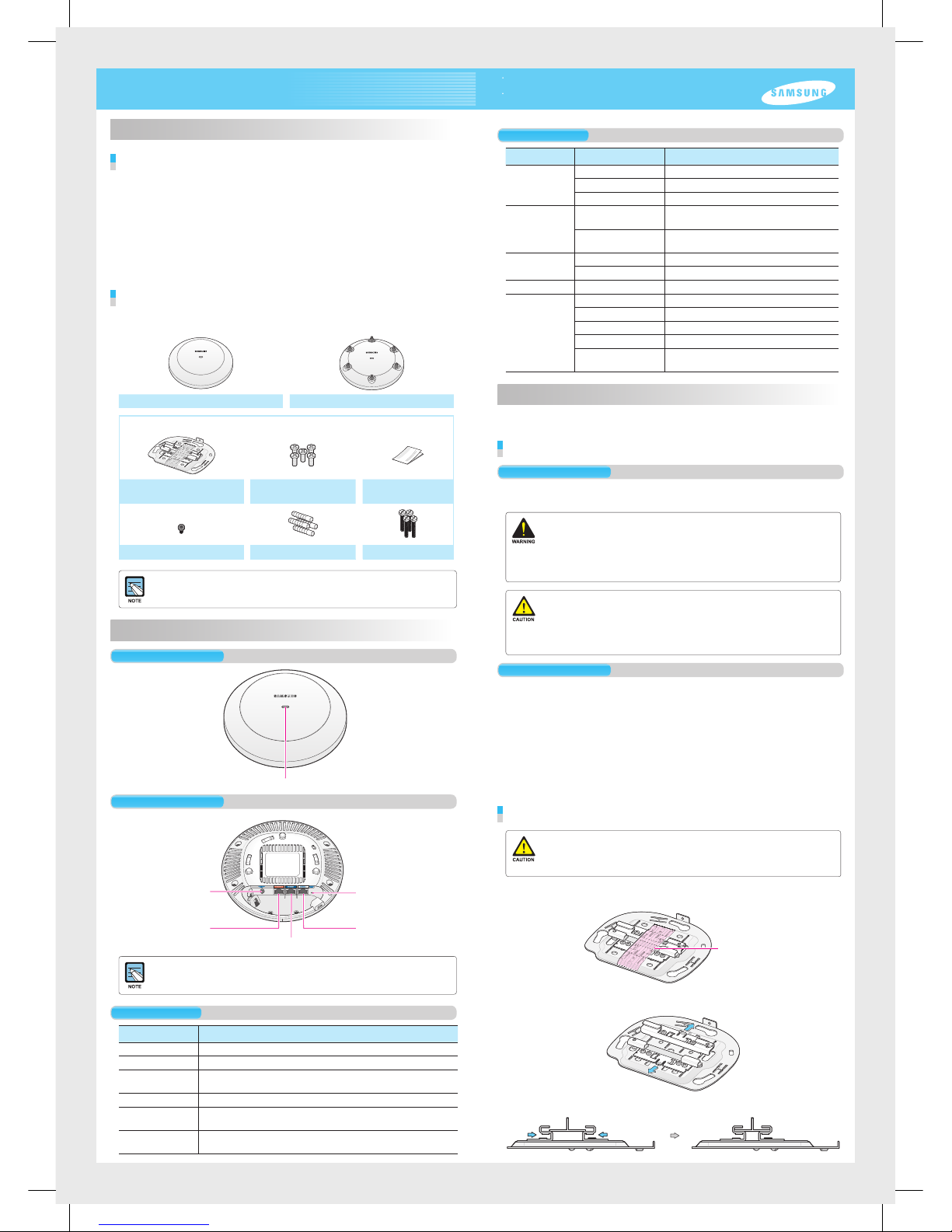
Names and Functions
Front View
Rear View
Ethernet Port
DC Input
Ethernet Port (PoE)
Factory Reset Switch
Console Port
Dust covers are installed on power ports (DC 48 V/0.75 A), Ethernet ports and console ports
(CONSOLE). Remove the covers before use.
Interface
Port Nam e Description
Status LED Displays the sta tus informatio n of the WEA400 Se ries via LED.
DC Input Used when a power ad apter is used for p ower supply.
Ethernet Po rt (PoE) Supports 100 0 BASE-T Gigabit Etherne t and PoE IEEE
802.3af/802.3at.
Ethernet Port Supports 100 0 BASE-T Gigabit Etherne t.
Console Port Used for check ing the operati onal status of the WE A400 series and
for CLI input.
Factory Rese t
Switch
Used for initia lization when co mmencing fac tory shipme nt of the
WEA400 se ries.
Status LED
Introduction
What is the WEA400 series?
The WEA400 series is an AP for the Samsung WE wirel ess LAN, which connects a UE
such as a smart phone, a tablet PC or a laptop that supports the wireless L AN to a wired
network. The WE A400 serie s supports the following features:
- IEEE 802.11a/b/g/n/ac standard
- PoE (Power over Ethernet) IEEE 802.3af/802.3at
- WEA412i: 2 × 2 MIMO (Multiple Input Multiple Ou tput)
- WEA403i/403e/413i: 3 × 3 MIMO (Multiple Input Multiple Ou tput)
- Wireless L AN through both 2.4 GHz and 5 GHz bandwidth simultaneously
- WEA403Si supports to connect various sensor s and equipments to a net work with
WLAN, BLE, ZigBee.
Components
After unpacki ng the WEA400 se ries, check wh ether all of the followin g components are
included.
WEA 403i/412i/413i /403 Si WEA403e
Common merchandise
Mounting Bracket
5 M3 × L6 screws
(Including 1 spare)
Installation Manual
Security Torx ( T10) Screw Plastic 4 anchor s M4 × L28 4 screws
- It is recommended to keep all packaging materials and the box.
- The power adapter and the external antenna for WEA403e are sold separately.
When necessary, please contact the place of purchase.
This manual describes the configuration of the Wireless Enterprise WEA400 series and its
installation procedures.
The installation procedures are described based on the WEA403i/412i/413i/403Si configurations.
The same installation procedures apply to the WEA403e model, except for the antenna installation.
Installation
The WEA400 series can be installed on ceilings or walls.
Please check whether all the components are included before installation.
Before Installation
Safety Requirements
Risks may be caused w hen the following safety warnings are not properly obser ved.
For safe use, make sure to be well-informed.
- There is an electrical risk with the product. Make sure that the power is off during installation
and do not proceed with the installation when there is current leakage. Use of products with
current leakage may cause serious electrical shock to the user.
- Wear anti-static gloves or take appropriate actions to prevent ESD when handling the product.
- Do not connect a phone line connector to the Etherner port. It may damage the product.
- This product must be connected to ta power supply in compliance with IEEE 802.3af/at or to a
limited power supply in compliance with IEC/EN/UL 60950-1.
- This product must be installed or removed only by appropriately-trained service personnel.
- This product operates with SELV (Safety Extra Low Voltage) according to IEC/EN/UL 60950-1.
- All interconnecting equipment including this product must be installed within the same
building. For details, refer to Environment A of IEEE 802.3af/at standard.
- This product must be installed with at least 3 m or more distance from the WiMAX/3G/4G
repeater or antenna.
Installation Instructions
The instructions below must be obse rved when installing.
- It must be installe d in a place that can be e asily accessed for product installation, cable
connection and maintenance.
- The PoE LAN ca ble must be always installed away from any electrical interfe rence
source such as power lines, fluoresc ent lights or transmitters.
- The PoE LAN ca ble must be CAT 5E or higher.
- When PoE is unavaila ble, a power adapter (sold separately) can be used.
The 3-pin (including ground) power s ocket that supplies 100~240 V AC, 50~60 Hz
must be located withi n 2 m from each equipment and the power must be supplied
through an independent circuit bre aker. It is recommended to use the e quipment that
uses a filter or a surge.
Installation on Ceilings (When the ceiling type is T-bar)
- When incorrectly installed on the ceiling, the WEA400 series may drop onto a person or
equipment. Therefore, make sure to fix it firmly.
- If the ceiling type is not T-Bar, please refer to the ‘Installation Manual’ provided separately.
For this installation manual, please contact the dealer.
1.
Remove the holding ta pe that was attached to fix the ceiling clip.
Holding tape
2.
Open the ceilin g clip so that it is wide r than the width of the T-bar.
3.
Move the ceiling clip s o that it is appropriate for the T-bar width.
Status LED
LED Status Description
System star t
status
White On Initial LED statu s
Blue On Devic e reset and test i n progress
Red On Booting failur e (Device reset f ailure)
Provisioning
Status
Red, green and o ff
repeated
APC connection in progress
(Network link n ormal)
Green blinki ng CAPWAP connection in progress
(APC serve r connection n ormal)
Normal
operation status
Green On When there is no c onnected wire less UE
Blue On When t here is a connec ted wireless U E
Upgrade Green blinki ng Software upgrade in progress
Error status Red blinking Physical conne ction error of n etwork
Yellow blinking IP address conflict
Purple blinkin g Dynamic IP add ress allocat ion failure
Bluish-green blinking Log ical connec tion error of net work
Red, green and o ff
repeated
Wireless interface error
WEA400 Series Quick Installation Manual

4.
Use a hammer to inser t 4 plastic
anchors into the drilled holes on
the wall. Align the inserted plastic
anchors and the screw holes of
the bracket. Fix the bracket to the
wall by fastening four M4 × L28
screws.
5.
Insert a L AN cable into the Ethernet port (PoE)
on the back side of the WE A400 serie s.
If PoE is not supported, connect the
power adapter to the DC input on the
back of the WEA400 series.
The wall
For the WEA403e model, remove the protection cap from the antenna connector and install the
external antenna (separately purchased). The 3 types of antennas that can be installed to the
WEA403e model are listed below. (More antenna types may be added in the future.)
Low gain dipole antenna Patch antenna High gain dipole antenna
Installing Anti-Theft Lock Cable
When installing the WEA400 series AP in a public place, it is recommended to use anti-theft
lock cables to prevent any loss. (An anti-theft lock cable can be purchased separately and a
variety of products can be found in the market.)
1.
Connect the anti-theft lock cable to the WEA400 series AP.
or
2.
Turn the lock cable key to lock the cable.
3.
Remove the key from the lock cable and keep it in a separate location.
Using the anti-theft Trox screws
The WEA400 series AP products can be prevented from being stolen when fastening the Trox
screws as shown below. (Trox screws can be easily fastened when they are fixed to the mount
bracket before assembling the AP product.)
This equip ment has been tes ted and found to compl y with the limits for a C lass B digital de vice, pursuant to pa rt 15 of the
FCC Rules. T hese limits are de signed to provide r easonable prote ction against ha rmful interfer ence in a residen tial installati on.
This equip ment generates , uses and can radi ate radio frequen cy energy and, if not i nstalled and use d in accordance w ith the
instructi ons, may cause har mful interfere nce to radio commun ications. Howeve r, there is no guarantee t hat interferenc e will not
occur in a par ticular insta llation. If this eq uipment does ca use harmful inter ference to radio o r television rec eption, which can b e
determine d by turning the equ ipment off and on, t he user is encour aged to try to correc t the interferen ce by one or more of the
following measures:
- Reorient o r relocate the rece iving antenna.
- Increase t he separation bet ween the equipm ent and receiver.
- Connect th e equipment into an o utlet on a circuit d ifferent from th at to which the recei ver is connected.
- Consult th e dealer or an expe rienced radio /TV technic ian for help.
Changes or modifications not expressly approved by the party responsible for compliance
could void the user’s authority to operate the equipment.
The 5150-5250 MHz band i s restricted to indo or use only.
This devic e complies with I ndustry Canad a licence-exem pt RSS standard(s). Op eration is subjec t to the following two c onditions:
(1) this device may no t cause interfer ence, and (2) this devi cemust accept an y interference, i ncluding inter ference that may c ause
undesired operation of thedevice.
Le présent a ppareil est confo rme aux CNR d’Indust rie Canada appli cables aux app areils radio exem pts de licence.
L’exploitation est auto risée aux deux co nditions suiva ntes: (1) l’appareil ne doit pa s produire de broui llage, et (2) l’utilisate ur
de l'appareil d oit accepter tout b rouillage radi oélectrique s ubi, même si le broui llage est susce ptible d’en comprome ttre le
fonctionnement.
FCC RF Radiation Exposure Statement:
This equip ment complies w ith FCC RF radiatio n exposure limits s et forth for an unco ntrolled enviro nment.
This equip ment should be in stalled and ope rated with a minimum d istance of 50 cm bet ween the radiator a nd your body.
This trans mitter must not be co -located or oper ating in conjunc tion with any other an tenna or transmit ter.
RSS-102 RF Exposure
L’antenne (ou les antenne s) doit être instal lée de façon à mai ntenir à tout insta nt une distance m inimum de au moin s 50 cm entre la sourc e
de radiatio n (l’antenne) et toute pe rsonne physiq ue. Cet apparei l ne doit pas être ins tallé ou utilis é en conjonctio n avec une autre ante nne
ou émetteu r.
Class B Equipment (For Home Use Broadcasting & Communication Equipment)
This equip ment is home use (Cl ass B) electroma gnetic wave suitab ility equipme nt and to be used main ly at home and it can
be used in all a reas.
Electromagnetic Wave Suitability Notice
Regulatory Information
‘Hereby, Samsung Electronics, declares that this WEA400 is in compliance with the essential requirements and other relevant provisions
of Directive 1999/5/EC.’
The original Declaration of Conformity may be found at http://www.samsungdocs.com, go to Search Product and enter the model name.
AEEE Yönetmeliğine Uygundur (Compliant with WEEE)
http://www.samsungenterprise.com
Part No.: EC68-00179A (Ver.3.0)
4.
Fix the ceiling clip in place by
fastening the 4 designated screws.
Screws for
fixing the
ceiling clip
5.
Fix the T-bar in place by fastening
the screws (total of 2) that are on
the ceiling clip.
Screws for
fixing T-bar
If the T-bar size of the ceiling is 15 mm, 24 mm or
38 mm, the position to fix the ceiling clip can be
checked from the bottom surface of the mount
bracket. If the T-bar size is unknown, push the
ceiling clip to check the fixing positions.
6.
Pull out a LAN cable through a hole o n the ceiling and connect is to an Ethernet p ort
(PoE) on the back sid e of the WEA400 series.
Exterior of the ceiling
If PoE is not supported, connect the power adapter to the DC input on the back side of the
WEA400 series. The output of the power adapter is 48 V/0.75 A and is not compatible with the
12 V/2 A output power adapter that is used by the previous WEA302i/303i/303e AP.
7.
Align the WEA400 series with the 3 holes on the mount bracket and then turn
clockwise to fix it in place. Clean up the ceiling and other cables.
Interior of the ceiling
Installation on Walls
1.
Remove the holding ta pe that was attached to fix the ceiling clip.
Holding tape
2.
Remove the ceiling clip from the mount brac ket.
3.
Place the mount bracket on the wall.
Mark and drill 4 screws in appropriate spots.
 Loading...