

Page 1
WEA400 Series Quick Installation Manual
This manual describes the configuration of the Wireless Enterprise WEA400 series and its
installation procedures.
The installation procedures are described based on the WEA403i/412i/413i/403Si configurations.
The same installation procedures apply to the WEA403e model, except for the antenna installation.
Introduction
What is the WEA400 series?
The WEA400 series is an AP for the Samsung WE wireless LAN, which connects a UE
such as a smart phone, a tablet PC or a laptop that supports the wireless LAN to a wired
network. The WEA400 series supports the following features:
- IEEE 802.11a/b/g/n/ac standard
- PoE (Power over Ethernet) IEEE 802.3af/802.3at
- WEA412i: 2 × 2 MIMO (Multiple Input Multiple Output)
- WEA403i/403e/413i: 3 × 3 MIMO (Multiple Input Multiple Output)
- Wireless LAN through both 2.4 GHz and 5 GHz bandwidth simultaneously
- WEA403Si supports to connect various sensors and equipments to a network with
WLAN, BLE, ZigBee.
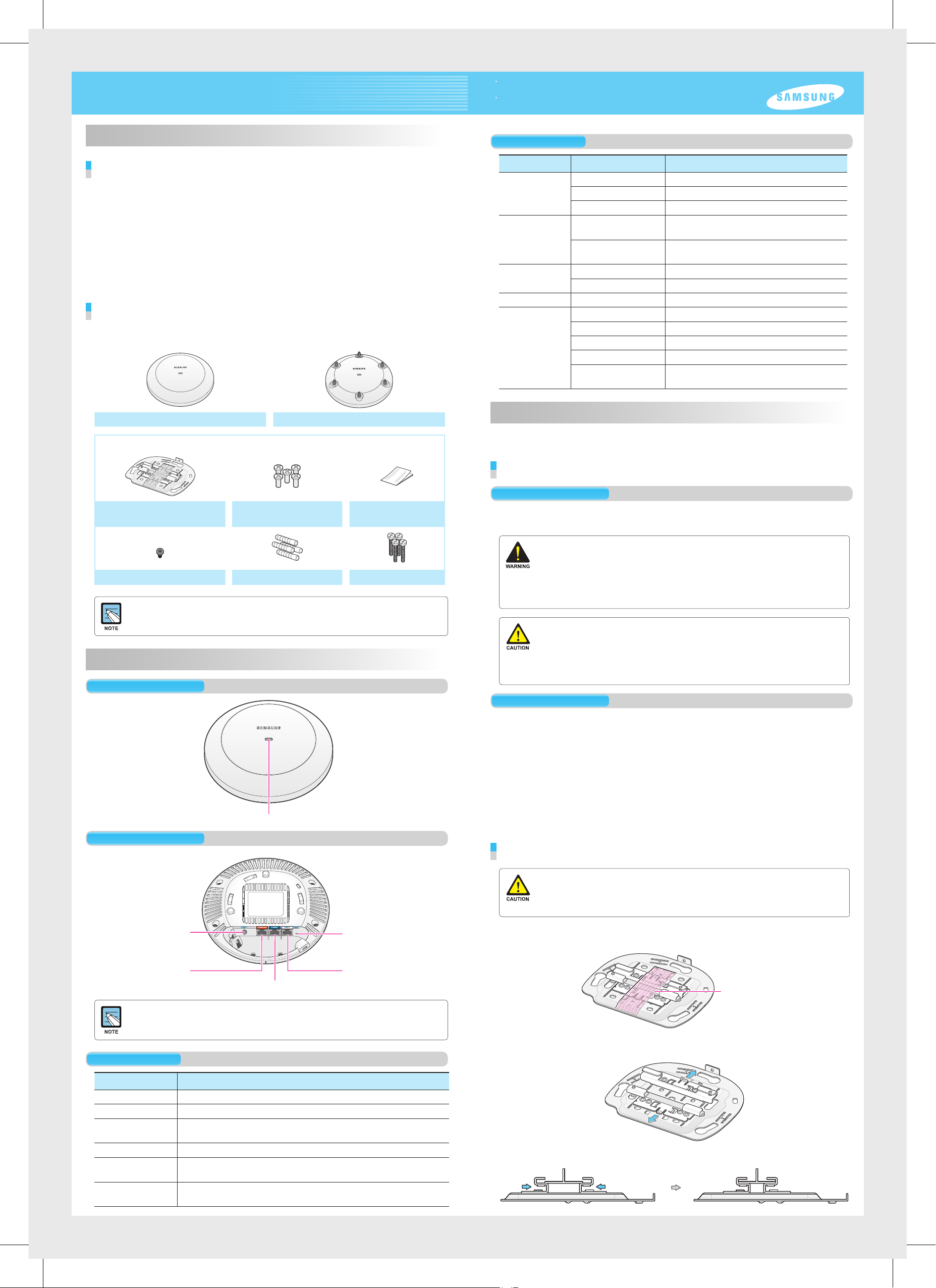
Components
After unpacking the WEA400 series, check whether all of the following components are
included.
WEA403i/412i/413i/403Si WEA403e
Common merchandise
Status LED
LED Status Description
System start
status
Provisioning
Status
Normal
operation status
Upgrade Green blinking Software upgrade in progress
Error status Red blinking Physical connection error of network
White On Initial LED status
Blue On Device reset and test in progress
Red On Booting failure (Device reset failure)
Red, green and off
repeated
Green blinking CAPWAP connection in progress
Green On When there is no connected wireless UE
Blue On When there is a connected wireless UE
Yellow blinking IP address conflict
Purple blinking Dynamic IP address allocation failure
Bluish-green blinking Logical connection error of network
Red, green and off
repeated
APC connection in progress
(Network link normal)
(APC server connection normal)
Wireless interface error
Installation
The WEA400 series can be installed on ceilings or walls.
Please check whether all the components are included before installation.
Mounting Bracket
5 M3 × L6 screws
(Including 1 spare)
Installation Manual
Security Torx (T10) Screw Plastic 4 anchors M4 × L28 4 screws
- It is recommended to keep all packaging materials and the box.
- The power adapter and the external antenna for WEA403e are sold separately.
When necessary, please contact the place of purchase.
Names and Functions
Front View
Status LED
Rear View
Before Installation
Safety Requirements
Risks may be caused when the following safety warnings are not properly observed.
For safe use, make sure to be well-informed.
- There is an electrical risk with the product. Make sure that the power is off during installation
and do not proceed with the installation when there is current leakage. Use of products with
current leakage may cause serious electrical shock to the user.
- Wear anti-static gloves or take appropriate actions to prevent ESD when handling the product.
- Do not connect a phone line connector to the Etherner port. It may damage the product.
- This product must be connected to ta power supply in compliance with IEEE 802.3af/at or to a
limited power supply in compliance with IEC/EN/UL 60950-1.
- This product must be installed or removed only by appropriately-trained service personnel.
- This product operates with SELV (Safety Extra Low Voltage) according to IEC/EN/UL 60950-1.
- All interconnecting equipment including this product must be installed within the same
building. For details, refer to Environment A of IEEE 802.3af/at standard.
- This product must be installed with at least 3 m or more distance from the WiMAX/3G/4G
repeater or antenna.
Installation Instructions
The instructions below must be observed when installing.
- It must be installed in a place that can be easily accessed for product installation, cable
connection and maintenance.
- The PoE LAN cable must be always installed away from any electrical interference
source such as power lines, fluorescent lights or transmitters.
- The PoE LAN cable must be CAT 5E or higher.
- When PoE is unavailable, a power adapter (sold separately) can be used.
The 3-pin (including ground) power socket that supplies 100~240 V AC, 50~60 Hz
must be located within 2 m from each equipment and the power must be supplied
through an independent circuit breaker. It is recommended to use the equipment that
uses a filter or a surge.
Installation on Ceilings (When the ceiling type is T-bar)
DC Input
Ethernet Port (PoE)
Ethernet Port
Dust covers are installed on power ports (DC 48 V/0.75 A), Ethernet ports and console ports
(CONSOLE). Remove the covers before use.
Factory Reset Switch
Console Port
Interface
Port Name Description
Status LED Displays the status information of the WEA400 Series via LED.
DC Input Used when a power adapter is used for power supply.
Ethernet Port (PoE) Supports 1000 BASE-T Gigabit Ethernet and PoE IEEE
802.3af/802.3at.
Ethernet Port Supports 1000 BASE-T Gigabit Ethernet.
Console Port Used for checking the operational status of the WEA400 series and
for CLI input.
Factory Reset
Switch
Used for initialization when commencing factory shipment of the
WEA400 series.
- When incorrectly installed on the ceiling, the WEA400 series may drop onto a person or
equipment. Therefore, make sure to fix it firmly.
- If the ceiling type is not T-Bar, please refer to the ‘Installation Manual’ provided separately.
For this installation manual, please contact the dealer.
Remove the holding tape that was attached to fix the ceiling clip.
1.
Holding tape
Open the ceiling clip so that it is wider than the width of the T-bar.
2.
Move the ceiling clip so that it is appropriate for the T-bar width.
3.
Page 2
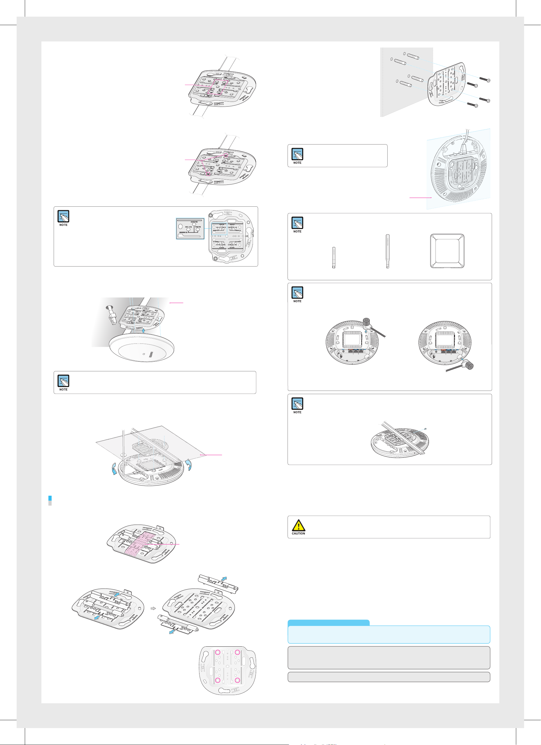
Fix the ceiling clip in place by
4.
fastening the 4 designated screws.
Screws for
fixing the
ceiling clip
Use a hammer to insert 4 plastic
4.
anchors into the drilled holes on
the wall. Align the inserted plastic
anchors and the screw holes of
the bracket. Fix the bracket to the
wall by fastening four M4 × L28
screws.
Fix the T-bar in place by fastening
5.
the screws (total of 2) that are on
the ceiling clip.
Screws for
fixing T-bar
If the T-bar size of the ceiling is 15 mm, 24 mm or
38 mm, the position to fix the ceiling clip can be
checked from the bottom surface of the mount
bracket. If the T-bar size is unknown, push the
ceiling clip to check the fixing positions.
Pull out a LAN cable through a hole on the ceiling and connect is to an Ethernet port
6.
(PoE) on the back side of the WEA400 series.
Exterior of the ceiling
Insert a LAN cable into the Ethernet port (PoE)
5.
on the back side of the WEA400 series.
If PoE is not supported, connect the
power adapter to the DC input on the
back of the WEA400 series.
For the WEA403e model, remove the protection cap from the antenna connector and install the
external antenna (separately purchased). The 3 types of antennas that can be installed to the
WEA403e model are listed below. (More antenna types may be added in the future.)
Low gain dipole antenna Patch antenna High gain dipole antenna
Installing Anti-Theft Lock Cable
When installing the WEA400 series AP in a public place, it is recommended to use anti-theft
lock cables to prevent any loss. (An anti-theft lock cable can be purchased separately and a
variety of products can be found in the market.)
1.
Connect the anti-theft lock cable to the WEA400 series AP.
The wall
If PoE is not supported, connect the power adapter to the DC input on the back side of the
WEA400 series. The output of the power adapter is 48 V/0.75 A and is not compatible with the
12 V/2 A output power adapter that is used by the previous WEA302i/303i/303e AP.
Align the WEA400 series with the 3 holes on the mount bracket and then turn
7.
clockwise to fix it in place. Clean up the ceiling and other cables.
Installation on Walls
Remove the holding tape that was attached to fix the ceiling clip.
1.
Interior of the ceiling
or
2.
Turn the lock cable key to lock the cable.
3.
Remove the key from the lock cable and keep it in a separate location.
Using the anti-theft Trox screws
The WEA400 series AP products can be prevented from being stolen when fastening the Trox
screws as shown below. (Trox screws can be easily fastened when they are fixed to the mount
bracket before assembling the AP product.)
This eq uipme nt has been tested a nd found to c omply with the limits for a Class B dig ital device, pursuant to p art 15 of the
FCC Rule s. Thes e limits are desi gned to provide reasonable protection against ha rmful interfe rence in a reside ntial installation.
This eq uipme nt generates, uses and ca n radiate radio fre quenc y energy and, if not i nstalled and used in acc ordance with the
instru ctions, may cause harmful inter ference to radio c ommunications. Howeve r, there is no gu arantee that interference will not
occur in a parti cular install ation. If this equi pment does cau se harmful inter ference to radi o or telev ision re ception, which can be
determ ined by turning th e equipment of f and on, the user is encoura ged to try to correct the interfere nce by one o r more of the
following measures:
- Reori ent or relocate the receiving ante nna.
- Increase the se paration betwe en the eq uipment and rec eiver.
- Conne ct the equipment into an outlet on a circuit differe nt from that to which the recei ver is connected.
- Consult the dealer or an experi enced radio/ TV tec hnici an for help.
Changes or modifications not expressly approved by the party responsible for compliance
could void the user’s authority to operate the equipment.
Remove the ceiling clip from the mount bracket.
2.
Place the mount bracket on the wall.
3.
Mark and drill 4 screws in appropriate spots.
Holding tape
The 5150-5250 MHz band is res tricted to indoor u se only.
This device complies with Industry Canada licence-exempt RSS standard(s). Operation is subje ct to the following t wo conditions:
(1) this device may not cau se inter ference, and (2) thi s devicemust ac cept any i nterference, includ ing interfere nce that may cause
undesired operation of thedevice.
Le prése nt appa reil est conforme aux CNR d’Industrie Canad a applicable s aux appareils radio exempts de lic ence.
L’exploitation est autorisé e aux deux condi tions suivante s: (1) l’appareil ne doit pas produire d e brouil lage, et (2) l’utilisateur
de l'appareil doit accepte r tout brouillag e radioélectr ique subi, même s i le broui llage e st susceptible d’en compromettre le
fonctionnement.
FCC RF Ra diation Exposure Statement:
This eq uipme nt compl ies with FCC RF radiation ex posure l imits se t forth for an unco ntrolled environment.
This eq uipme nt should be installed and operated with a mi nimum distanc e of 50 cm bet ween the radiator and your body.
This transmit ter must not be co-l ocated o r operating in conjunction with a ny other antenna or transmi tter.
RSS-102 RF Exposure
L’antenne (ou le s antenn es) doit être installée de façon à ma intenir à tout instant une di stance minimu m de au moins 50 cm entre la sourc e
de radiation (l’ante nne) et tou te perso nne phys ique. Cet appare il ne doi t pas être installé ou utilisé en conjoncti on avec une autre antenne
ou émet teur.
Electromagnetic Wave Suitability Notice
Class B Equipment (For Home Use Broadcasting & Communication Equipment)
This eq uipme nt is home use (Clas s B) electromagnetic wave suitabi lity equipme nt and to be used mainly at home and it can
be used in all areas.
Regulatory Information
‘Hereby, Samsung Electronics, declares that this WEA400 is in compliance with the essential requirements and other relevant provisions
of Directive 1999/5/EC.’
The original Declaration of Conformity may be found at http://www.samsungdocs.com, go to Search Product and enter the model name.
AEEE Yönetmeliğine Uygundur (Compliant with WEEE)
http://www.samsungenterprise.com
Part No.: EC68-00179A (Ver.3.0)
 Loading...