

Samsung WEA302I Installation Manual
WEA302i/303i/303e Installation Manual
This manual describes the configuration of Wireless Enterprise WEA302i/303i/303e and how to
install WEA302i/303i/303e.
The instruction on how to install is described based the WEA302i/303i model, and the instruction
on how to install the WEA303e model is same except for the installation of an external antenna.
Introduction
What is WEA302i/303i/303e?
The WEA302i/303i/303e is AP for Samsung WE wireless LAN.
It connects the UE that supports wireless LAN such as a smart phone, tablet PC, or notebook to a
wired network. The WEA302i/303i/303e supports the following features:
- IEEE 802.11a/b/g/n standard
- Power over Ethernet (PoE) IEEE 802.3af
- WEA302i: 2 × 2 MIMO (Multiple Input Multiple Output)
- WEA303i/303e: 3 × 3 MIMO (Multiple Input Multiple Output)
- Wireless LAN through both 2.4 GHz and 5 GHz ISM bandwidth
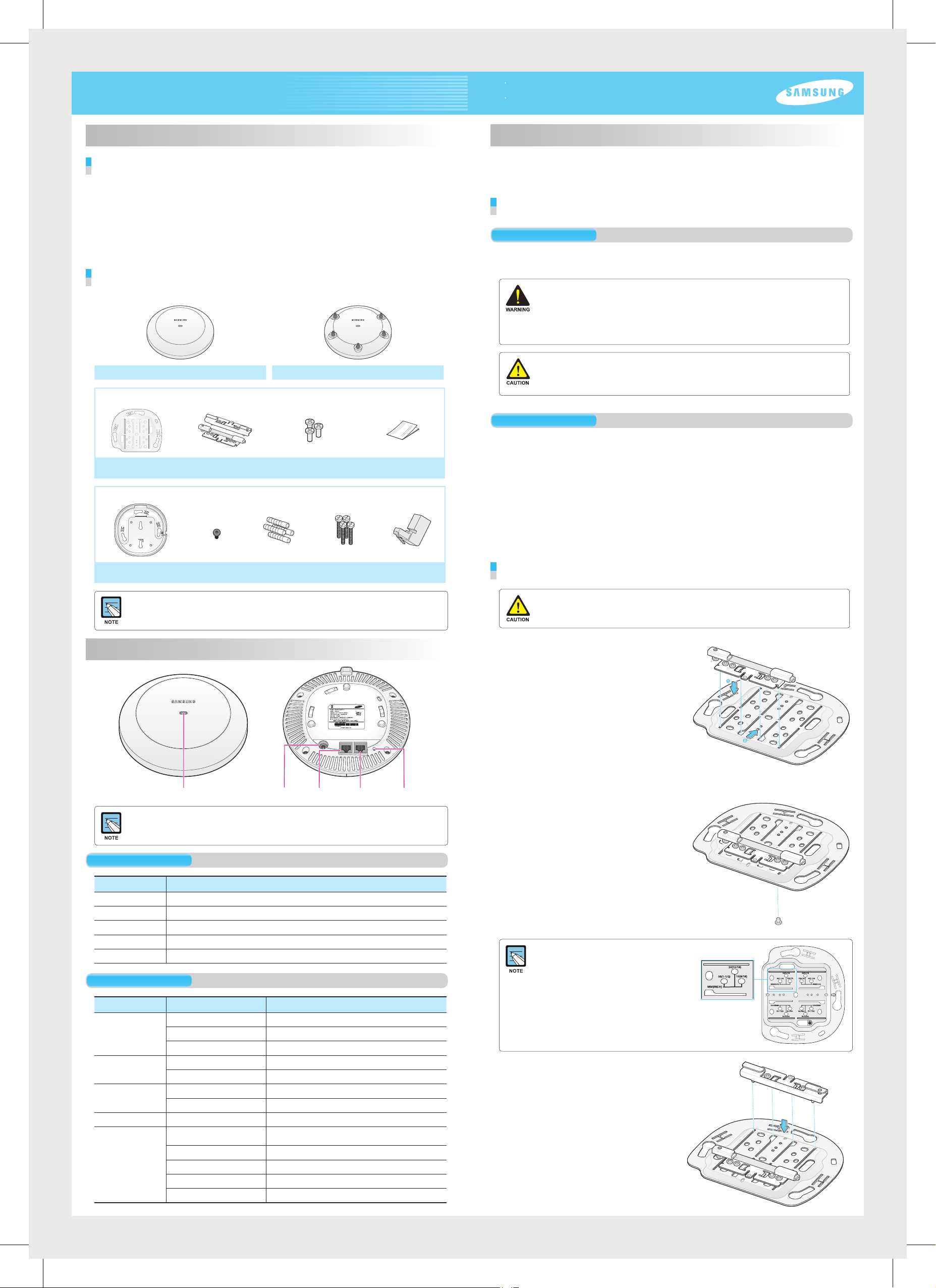
Component
After unpacking the WEA302i/303i/303e, check whether all of the following items are included.
WEA302i/303i WEA303e
Common merchandise
Installation
The WEA302i/303i/303e can be installed on a ceiling or wall. Please check whether all the components
are included before installation.
Before Installation
Safety Requirements
If the below safety warnings are not properly observed, it may cause a risk.
Make sure to be informed for safe use.
- There is an electrical risk with the product. Make sure that the power is turned off during installation.
Do not proceed with the installation when there is current leakage. Otherwise, this may cause serious
personal injury.
- Wear anti-static gloves or take an appropriate action to prevent ESD during product handling.
- Do not connect a phone line connector to an Ethernet port. This may damage the product.
- This product must be connected to a power supply in compliance with IEEE 802.3af or to a limited power
supply in compliance with IEC60950.
- This product must be installed or removed only by appropriately trained service personnel.
- This product is operating in the Safety Extra Low Voltage (SELV) state according to IEC60950.
- All the connected equipment including this product must be installed inside of the same building.
For more information, refer to the Environment A of IEEE 802.3af standard.
Installation Instructions
Ceiling bracket Two ceiling clips
Wall mount bracket installation set (sold separately)
Wall mount bracket
- It is recommended to keep all the packing materials and box.
- The wall mount bracket installation set, power adaptor, and external antenna for WEA303e are sold
separately.
- The cable hole guide seat is provided separately.
Security torx
(T10) screw
Name and Function
Three M3 × L6 screws
(including 1 spare)
Four plastic
anchors
M4 × L28
Four screws
Installation Manual
RJ45 gender
The below instructions must be observed during installation.
- The system must be easily accessible for product installation, cable connection, or maintenance.
- The PoE LAN cable must be installed always away from an electrical interference source such as
power line, fluorescent light, radio, or transmitter.
- The PoE LAN cable must be CAT 5E or higher.
- If it is not easy to use PoE, a power adapter (sold separately) can be used.
The 3-pin (including ground) power consent that supplies 100-240 V AC, 50-60 Hz must be located
within 2 m from equipment and the power must be supplied through an independent circuit breaker.
It is recommended to use equipment that uses a filter or surge breaker.
- The ambient temperature must be maintained between 0'C and 45°C. The ambient humidity,
in absence of air pressure change, must be maintained between 10 % and 90 %.
Installation on a Ceiling
If the WEA302i/303i/303e is incorrectly installed on the ceiling, the product may drop onto a person or
equipment. Therefore, make sure to fix it firmly.
Place a ceiling bracket by making its convex part
1.
upward and align a ceiling clip to the groove of the
ceiling bracket and insert the clip to the position that
is shown in the figure.
Push and move the ceiling clip according to the
T-bar size of the ceiling.
Status LED Ethernet portDC input Console port Reset switch
Dust covers are installed on a power port (DC 12 V/2.0 A) and console port (CONSOLE).
Remove the cover before use.
Interface
Interface Description
Status LED Displays the status information of WEA302i/303i/303e with LED.
DC input Used when a power adaptor is used for power supply.
Ethernet port Supports 1000 BASE-T Gigabit Ethernet and PoE IEEE 802.3af standard.
Console port Checks the operation status of WEA302i/303i/303e and used for CLI input.
Reset switch Used to restart the WEA302i/303i/303e.
Status LED
LED Status Description
System start status White On Initial LED status
Blue On Device reset and test in progress
Red On Booting failure (Device reset failure)
Provisioning status Repeated Red, Green, and Off Connecting APC (network link normal status)
Blinking green
Normal operation
status
Upgrade Blinking blue Upgrading software
Fault status Blinking red
Green On When there is no connected wireless UE
Blue On When there is a connected wireless UE
Blinking orange IP address conflict
Blinking violet Dynamic IP Address allocation failure
Blinking bluish green Fixed IP check failure
Repeated Red, Blue, and Off Wireless interface fault status
Connecting CAPWAP link (APC server normal connection status)
Abnormal network link (checking link status after disconnection
or re-connection)
Fix the ceiling clip to the ceiling bracket by tightening
2.
one M3 × L6 screw to either of the two holes.
If the T-bar size of ceiling is 15 mm, 24 mm, or
38 mm, you can check a fixing position where a
ceiling clip can be fixed on the floor of ceiling
bracket.
If the T-bar size is unknown, tighten the two ceiling
clips using one screw each in the step 4.
Align the ceiling clip on the other side to the groove
3.
of ceiling bracket and insert the clip.
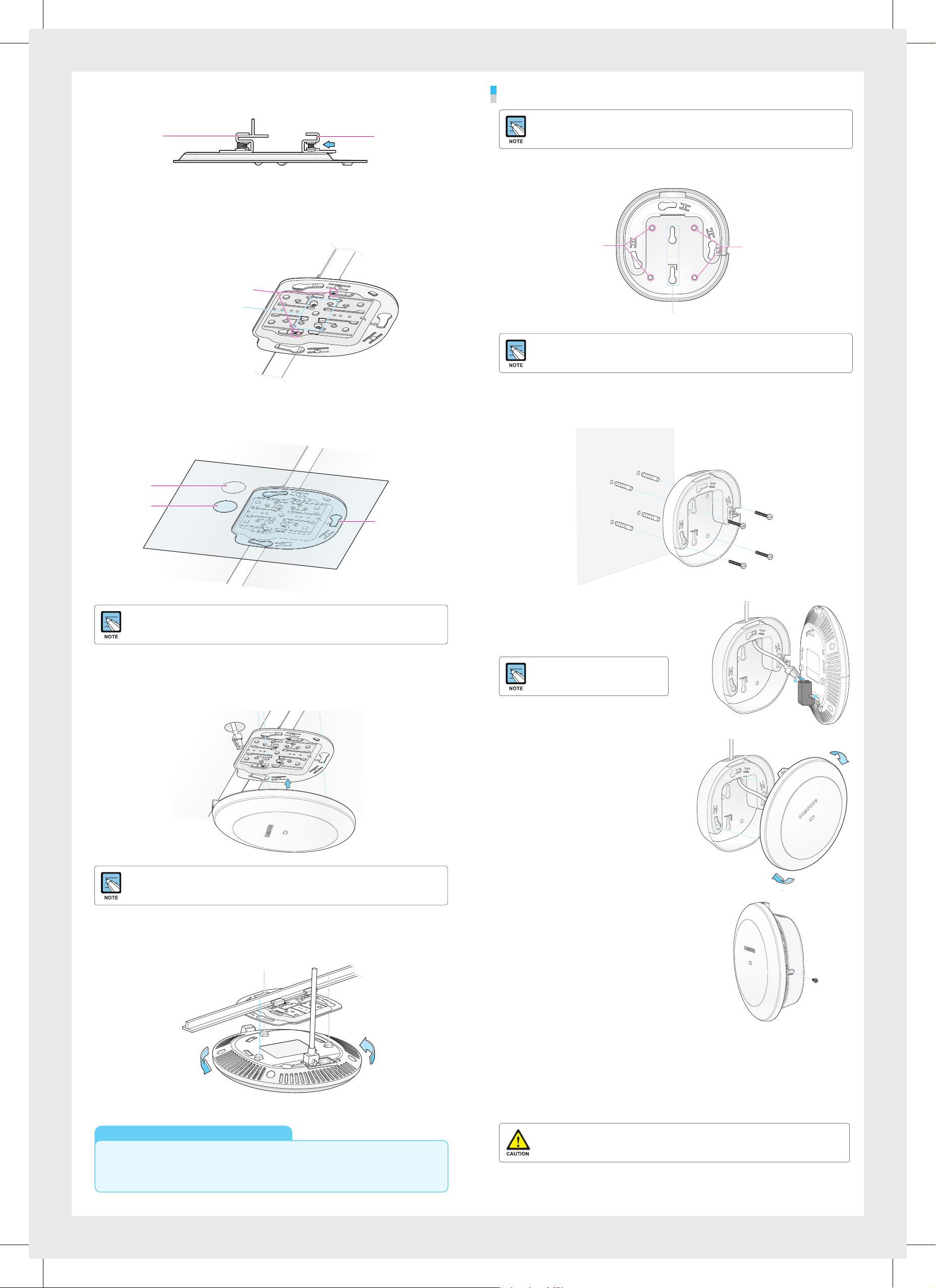
After inserting the ceiling clip that is fixed with a screw (A in the figure) to the T-bar, push and move
4.
the ceiling clip (B in the figure) on the other side according to the T-bar size.
Installation on a Wall
For installation on a wall, the wall mount bracket set (sold separately) is required.
A
[Side]
After tightening two T-bar fixing screws of the ceiling clip, and fix the pushed and moved ceiling
5.
B
clip by tightening one M3 × L6 screw to either of two holes.
As shown in the figure, the ceiling bracket is firmly fixed to the ceiling.
T-bar fixing screw
Ceiling clip fixing screw
Using a cable hole guide seat separately provided, mark a hole on the ceiling tex through which a cable
6.
will be drawn out and punch a hole.
A wall mount bracket has total 4 screw holes.
1.
Place the bracket on a wall and mark and drill 4 screw holes.
When 4 screws are used
When 2 screws are used
Two screws can be used for fixing depending on a wall to install.
Using a hammer, insert 4 plastic anchors to the holes.
2.
When 4 screws are used
Align the screw holes of the wall mount bracket to the holes where the plastic anchors are inserted,
and fix the wall mount bracket to the wall by tightening four M4 × L28 screws.
Ceiling Hole
Cable
Hole Position
The cable hole guide seat is provided separately. For more information, contact the dealer.
After separating the ceiling tex from the T-bar, draw out a LAN cable through the cable hole and
7.
Cable
Hole Guide Seat
connect it to the Ethernet port at the rear side of WEA302i/303i/303e.
First, connect a RJ45 gender to the Ethernet port on
3.
the rear side of WEA302i/303i/303e. And pass a LAN cable
through the hole at the top of wall mount bracket
and connect it to the RJ45 gender.
If PoE is not supported, connect the
power adaptor to the DC input on the
back of WEA302i/303i/303e.
After aligning the WEA302i/303i/303e to the three grooves
4.
of the wall mount bracket, fix the product by
turning it clockwise.
If PoE is not supported, connect the power adaptor to the DC input on the back of WEA302i/303i/303e.
After aligning the WEA302i/303i/303e to the three grooves of the ceiling bracket, fix the product by
8.
turning it clockwise. Arrange ceiling tex and other cables.
Electromagnetic Wave Suitability Notice
Class B Equipment (For Home Use Broadcasting & Communication Equipment)
This equipment is home use (Class B) electromagnetic wave suitability equipment and to be used
mainly at home and it can be used in all areas.
To prevent theft, tighten and fix security torx (T10) screws
5.
on the sides of wall mount bracket.
This equipment has been tested and found to comply with the limits for a Class B digital device, pursuant to part 15 of the FCC
Rules. These limits are designed to provide reasonable protection against harmful interference in a residential installation.
This equipment generates, uses and can radiate radio frequency energy and, if not installed and used in accordance with the
instructions, may cause harmful interference to radio communications. However, there is no guarantee that interference will not
occur in a particular installation. If this equipment does cause harmful interference to radio or television reception, which can be
determined by turning the equipment off and on, the user is encouraged to try to correct the interference by one or more of the
following measures:
- Reorient or relocate the receiving antenna.
- Increase the separation between the equipment and receiver.
- Connect the equipment into an outlet on a circuit different from that to which the receiver is connected.
- Consult the dealer or an experienced radio/TV technician for help.
Changes or modifications not expressly approved by the party responsible for compliance could void
the user’s authority to operate the equipment. Indoor use only.
FCC RF Radiation Exposure Statement:
This equipment complies with FCC RF radiation exposure limits set forth for an uncontrolled environment. This equipment
should be installed and operated with a minimum distance of 20 cm between the radiator and your body. This transmitter must
not be co-located or operating in conjunction with any other antenna or transmitter.
Part No.: EC68-00172A (Ver.2.0)
 Loading...