

Page 1
Samsung Electronics 3-1
3. Alignment and Adjustment
3-1. VCR Adjustment
3-1-1. VCR Adjustment Preparation
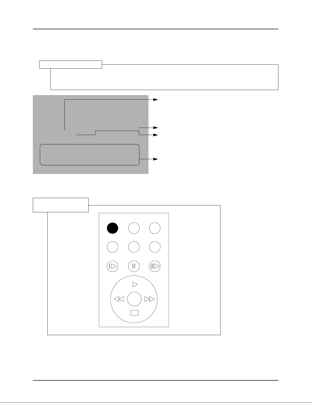
1. How to get into the VCR adjust mode.
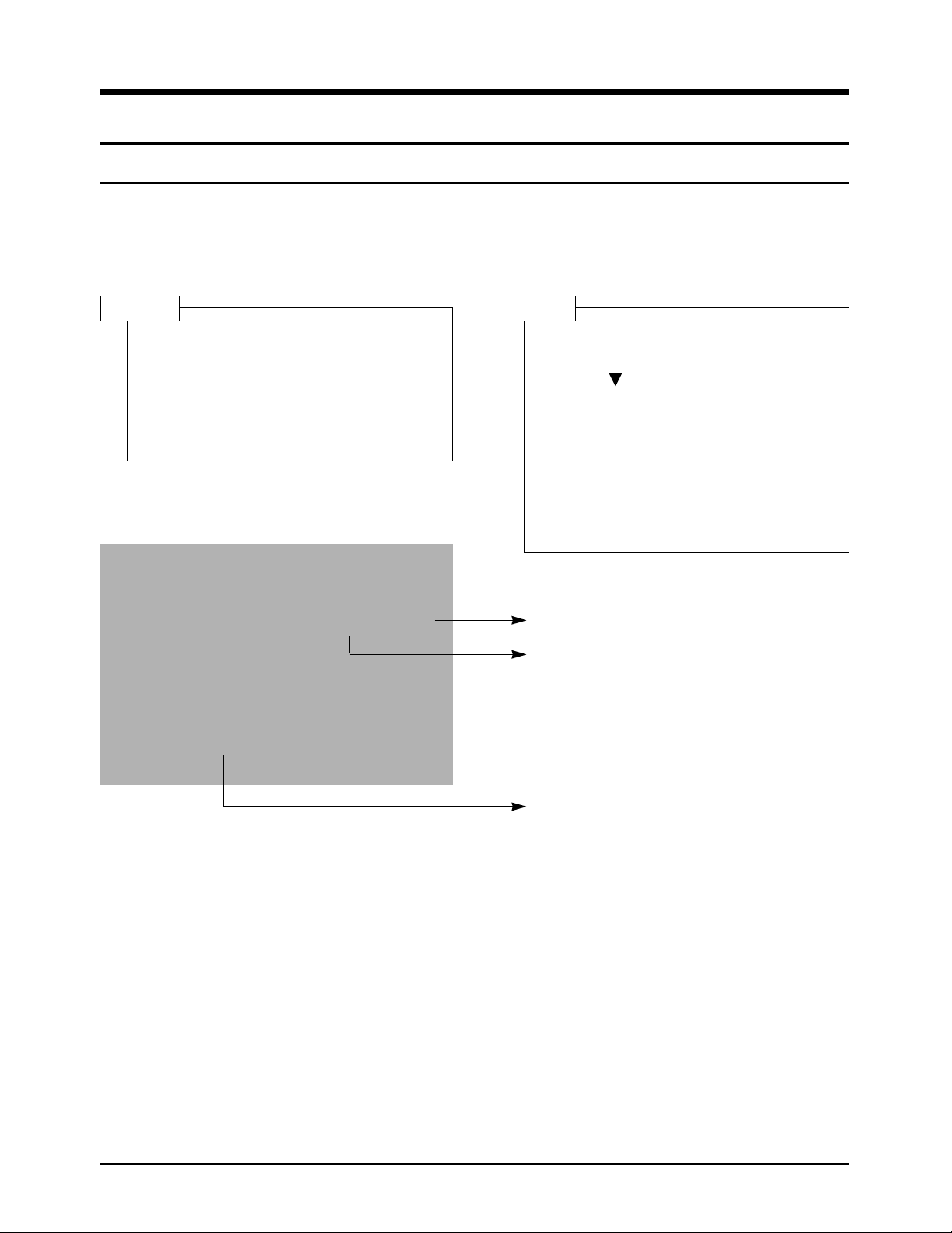
ADJ ->
PLAY
0: 27:00: 00
V-REF : 6BH
SP
27MIN
FF 01 80
Indicates the adjusted values
Indicates current adjustment item.
Indicates current value in the ZOOM
switch.
1) Connect the power source.
2) Set the mode switch of the video camera
to "PLAYER" position.
3) Insert standard tape into the video camera
and set to "PLAY" position.
STEP 1
1) Press and hold the "PLAY" button on the
video camera or the remote control and
"DOWN( )" button on the video camera
at the same time for more than 10 seconds.
2) When monitor OSD appears as shown
below, VCR adjustment mode has been
activated successfully.
3) When changing the adjustment item after
the adjusted value is designated, press the
“START/STOP” button.
STEP 2
S64 L00
Page 2
START/STOP PHOTO WIDE
SELF TIMER DISPLAY TELE
SLOW STILL F.ADV
W
T
Samsung Electronics3-2
Alignment and Adjustment
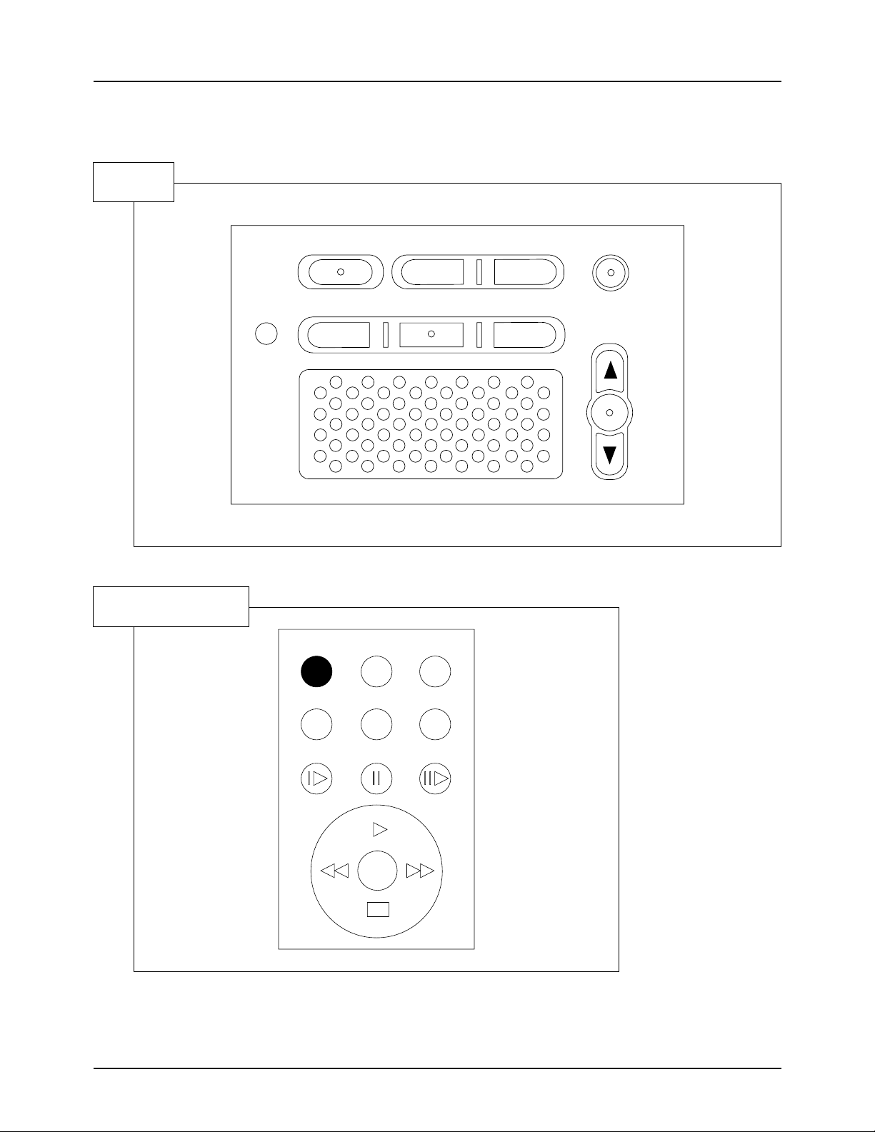
2. Buttons Location
SET
Remote Control
3. If you want to finish the adjustment mode, you have to do Power Reset.
The Power Reset means that you pull out the power source and pull in it again.
RESET
PROGRAM AE
A.DUB C.RESET OSD ON/OFF
DATE/TIME DSE
MENU
ON/OFF
ENTER
Page 3
Samsung Electronics 3-3
Alignment and Adjustment
3-1-2. VCR Adjustment
1. VCR Adjustment Items
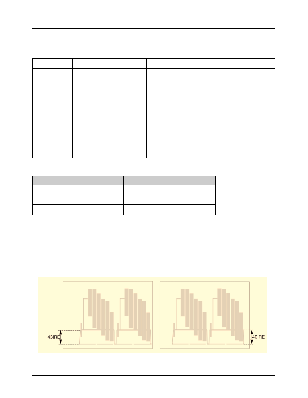
2. How to adjust Video-Reference (V-REF).
1) Connect video output cable to wave form scope. The wave form scope must be connected to monitor.
(75Ω termination)
2) Set to the VCR adjustment mode.
3) Adjust VREF so that SYNC level of video output signal is PAL(43 IRE) and NTSC(40 IRE).
Items Adj. value Description
V-REF Adjustment Video reference
EXTRA 7E Audio VCO PLL
RECCUR 80 REC current
A-REF1 80 Audio 48KHz mode
A-REF2 80 Audio 44.1KHz mode
A-REF3 80 Audio 32KHz mode
HDSWP Adjustment Head Adjust switch
ZOOMVR Adjustment Adjust center value in the ZOOM switch
OPTION ** RESERVED(fixed value)
PAL NTSC
Model Adj. value Model Adj. value
VP-D55 02 SCD55 12
VP-D60 AA SCD60 BE
VP-D65 FE
* Option
Page 4
Samsung Electronics3-4
Alignment and Adjustment
3. How to adjust Head Switching (HDSWP)
1) Connect No. 2 pin of WAFER CN603 (HEAD-SW signal) for adjustment to CH1 of oscilloscope.
2) Connect No. 3 pin of WAFER CN603 (ENVE-OUT signal) for adjustment to CH2 of oscilloscope.
3) Play standard color bar tape.
4) Select HDSW of the video adjustment mode.
5) Adjust so that the time between HEAD-SW START and G1 START OF ENVE-OUT is 141µs (±10µs).
4. Center Value Adjustment of Zoom Switch
1) Select ZOOMVR in the video adjustment mode.
2) Adjust ZOOM SW so that the switch is put in the middle of T and W.
3) Adjust ZOOMVR so that the current value of ZOOM SW is equal to the adjusted ZOOMVR value.
H’D-SW
ENVEOUT
141uS
G1
ADJ ->
PLAY
0: 27:00: 00
V-REF : 6BH
SP
27MIN
FF 01 80
S64 L00
(Current value of the Zoom SW)
Page 5
Samsung Electronics 3-5
Alignment and Adjustment
3-1-3. PRML Adjustment Preparation
1. How to set up PRML Adjustment Mode
REG : 00 2
PLAY
0:27:00:00
PLAY
S00L00
27MIN
SP
Indicates address of adjusting item by using from
00 to 24.
Indicates operating mode of PRML.
Indicates preset values.
1. Press the Display button in VCR adjustment mode.
2. When monitor OSD appears as shown below, PRML adjustment mode has been activated
successfully.
PRML Adjustment Setup
0C0
805
28A
000
#00
28A
000
21E
865
000
223
860
400
004
00C
600
FA2
Indicates digit of adjusting item by using 2, 1, and 0.
e.g.) Digit : 2, 1, 0 Adjustment
value : 0 C 0
2. Remote Control Button Location
3. Press the Address selection button(“START/STOP” button) to skip the next address in order to finish the
adjustment and store data. After finishing the adjustment, you have to do power reset.
*
The PRML BER will be set to the right adjustment when shipping out video camera and PCB ASSY from
factory.
START/STOP PHOTO WIDE
SELF TIMER DISPLAY TELE
SLOW STILL F.ADV
W
T
Remote Control
Page 6
Samsung Electronics3-6
Alignment and Adjustment
3-1-4. PRML Adjustment
Address
Function
MODE
SP
00
PGC/SQPI/FIRO
IDO/DOD/ATFAQ/FIR4
GDH0/FIR1H0
GDH1/FIR1H1
LPGC/DA TF/PGCEN/TDOI/FIR3H0
BPGC/FCLP/FIR3H1
LTG/LPGC/BPLG/TC13/TC2/FIR2
A TFFC/AGCT AR/A TFHG/HGSEL/SLEEP
DDOSC/SEFTH/DLZI/T ADAPT/VIT
ATFSEL/SYMC/DAMP
HLD/FCHO/BSTH0
CMXEN/FCH1/BSTH1
EZCNT/LPFBYP/PDTST/...
ATGH0/TCTCH0/TP1SEL
FRQ/RLZSEL/...
ATGCH1/TCTCH1/TSEL
AE/DZ/INTL/.../TWR
01
02
03
04
05
06
07
08
09
0A
0B
0C
0D
0E
0F
24
1. How to set up PRML Adjustment Mode
0C0
000
000
000
400
600
805
#00
21E
223
004
28A
28A
865
860
00C
FA2
0C0
000
2C0
2C0
400
600
805
#00
A1E
223
004
28A
28A
865
860
00C
7A2
0C0
000
2C0
2C0
400
600
805
#00
226
223
004
28A
28A
865
860
00C
FA2
0C0
000
2C0
2C0
400
600
805
#00
A26
223
004
28A
28A
835
830
00C
7A2
2. BER Adjustment Specifications (Reference)
1) Get into the VCR adjustment mode.
; Press and hold the “PLAY”button and “DOWN”button at the same time for more than 10 seconds.
2) Turn off Adaptive. . . . . . . . . . . . . . . . . . . . . . . . . . . . . . . . . . . . . . 7A2 ;REG24
3) Find out the optimally minimum BER value in REG. 12 BOOST.
start values . . . . . . . . . . . . . . . . . . . . . . . . . . . . . . . . . . . . . . . . . . . . .28A ;REG12
The optimum means the number of error is less than 10 ea. ;Current SCD55/VP-
D55 manufacturing
standard
If the minimum value is as the followings, designate as the right values.
Min . . . . . . . . . . . . . . . . . . . . . . . . . . . . . . . . . . . . . . . . . . . . . . . . . . ;Selection valueless
less than 18 . . . . . . . . . . . . . . . . . . . . . . . . . . . . . . . . . . . . . . . . .18 ;REG12 ===24A
19 . . . . . . . . . . . . . . . . . . . . . . . . . . . . . . . . . . . . . . . . . . . . . . . . .19 ;REG12 ===26A
20 . . . . . . . . . . . . . . . . . . . . . . . . . . . . . . . . . . . . . . . . . . . . . . . . .20 ;REG12 ===28A
21 . . . . . . . . . . . . . . . . . . . . . . . . . . . . . . . . . . . . . . . . . . . . . . . . .21 ;REG12 ===2AA
PB SEARCH PB SEARCH
LP
Page 7

Samsung Electronics 3-7
Alignment and Adjustment
4) Find out the optimally minimum BER value in REG. 11 BOOST.
Start values . . . . . . . . . . . . . . . . . . . . . . . . . . . . . . . . . . . . . . . .28A ;REG11
The optimum means the number of error is less than 10 ea. ;Current SCD55/VP-
D55 manufacturing
standard
If the min. and max. value is as the followings, designate as the right values.
Min . . . . . . . . . . . . . . . . . . . . . . . . . . . . . . . . . . . . . . . . . . . . . . . . . . ;Selection valueless
less than 18 . . . . . . . . . . . . . . . . . . . . . . . . . . . . . . . . . . . . . . . . .18 ;REG11 ===24A
19 . . . . . . . . . . . . . . . . . . . . . . . . . . . . . . . . . . . . . . . . . . . . . . . . .19 ;REG11 ===26A
20 . . . . . . . . . . . . . . . . . . . . . . . . . . . . . . . . . . . . . . . . . . . . . . . . .20 ;REG11 ===28A
21 . . . . . . . . . . . . . . . . . . . . . . . . . . . . . . . . . . . . . . . . . . . . . . . . .21 ;REG11 ===2AA
5) Turn on Adaptive. . . . . . . . . . . . . . . . . . . . . . . . . . . . . . . . . . . . . . . . . . ;REG24 ===FA2
6) Check the value is input to unit correctly.
Page 8

Samsung Electronics3-8
Alignment and Adjustment
3-2 Camera Adjustment
Note: How to adjust the camera system.
1) EEPROM stores confirmed adjustment value of each adjustment step.
2) DSP (Digital Signal Process : ICP06-MAIN BOARD) digitalizes the camera signal.
3) When changing ICP11-MAIN BOARD of EEPROM, readjust main board. While changing LCD
board-ICL202 and CVF board-ICV02, always readjust each part.
Since EEPROM stores confirmed adjustment value of each adjustment step, readjusting must be
performed in order to store the changed data.
4) Adjust the following items after changing LENS ASSY.
a. LENS ZOOM TRACK
b. AUTO HALL
c. AUTO IRIS
5) Adjust the following items after changing EEPROM and MAIN BOARD.
a. LENS ZOOM TRACK
b. AUTO HALL
c. AE TARGET
d. AUTO GAIN CONTROL
e. AUTO IRIS
f. AUTO WHITE BALANCE (indoor)
g. AUTO WHITE BALANCE (outdoor)
3-2-1 Adjustment Preparation
1. Measuring Instrument
1) DC power supply
2) Oscilloscope
3) PAL vectorscope, NTSC vectorscope
4) PAL wave form monitor, NTSC wave form monitor
5) PAL TV or monitor, NTSC TV or monitor
6) Color bar chart
Gray scale chart
3. Before you start
1) Use the buttons on the remote control when adjusting camera.
2) Press the "START/PAUSE" button when storing confirmed adjustment value of each adjustment step in
EEPROM.
3) There is a flicker on screen after finishing each adjustment step.
4) To clear the adjustment mode, pull out the power source.
2. Camera PCB configuration
1) MAIN PCB
2) CCD PCB
3) CVF PCB
4) LCD PCB
Page 9
Samsung Electronics 3-9
Alignment and Adjustment
4. Functions of each button on the Remote Control
Description
Button
START/STOP (Confirm)
STOP (Data Down)
PLAY (Data Up)
FF (Mode Up)
REW (Mode Down)
STILL (Data/Mode)
DISPLAY
SELF TIMER
Stores changed value in the adjustment and auto adjustment mode.
Changes data in the adjustment state.
Changes mode.
Uses this button in lens and auto adjustment(indicates MF on screen.).
PRE-CONFIRM
Note: In service adjustment mode, button names
are different from those in customer function
control mode.
e.g.) "START/STOP" is the same as "Confirm".
5. How to set up the camera adjustment mode
1) Connect the power source
(battery/DC cable).
2) Open Housing from video
camera.
3) Set the "CAMERA/VCR" switch to "CAMERA" position.
4) The OSD appears.
STEP 1
Press and hold the "EDIT(+)" button and
"ENTER" button on the video camera at the
same time for more than 5 seconds.
STEP 2
Monitor OSD shows "16D XX XX". Then
camera adjustment mode has been activated
successfully.
STEP 3
Note : "XX" indicates variable values.
In adjustment mode, the buttons of the remote control is as the followings.
START/STOP PHOTO WIDE
SELF TIMER DISPLAY TELE
SLOW STILL F.ADV
W
T
Page 10

Samsung Electronics3-10
Alignment and Adjustment
0 00 00 00 00 00 D_DFP_DUMMY0
1 00 00 00 00 00 D_DFP_DZOOM_MODE
2 00 00 00 00 00 D_DFP_HZ_INT
3 00 00 00 00 00 D_DFP_HZ_SUB
4 00 00 00 00 00 D_DFP_HZ_STEP
5 00 00 00 00 00 D_DFP_VZ_SUB
6 00 00 00 00 00 D_DFP_VZ_STEP
7 78 78 78 78 78 D_DFP_EIS_I
8 2C 2C 31 31 31 D_DFP_FST_NO_L
9 08 08 08 08 08 D_DFP_FST_NO_H
A 00 00 00 00 00 D_DFP_SHUTTER_L
B 00 00 00 00 00 D_DFP_SHUTTER_H
C 03 03 03 03 03 D_DFP_TG_MODE
D 00 00 00 00 00 D_DFP_DELAY_CONT
E 00 00 00 00 00 D_DFP_RGB_SEL
F 02 02 02 02 02 D_DFP_GMA1
10 08 08 08 08 08 D_DFP_GMA2
11 13 13 13 13 13 D_DFP_GMA3
12 28 28 28 28 28 D_DFP_GMA4
13 46 46 46 46 46 D_DFP_GMA5
14 68 68 68 68 68 D_DFP_GMA6
15 80 80 80 80 80 D_DFP_GMA7
16 98 98 98 98 98 D_DFP_GMA8
17 02 02 02 02 02 D_DFP_GHB1
18 08 08 08 08 08 D_DFP_GHB2
19 13 13 13 13 13 D_DFP_GHB3
1A 28 28 28 28 28 D_DFP_GHB4
1B 44 44 44 44 44 D_DFP_GHB5
1C 66 66 66 66 66 D_DFP_GHB6
1D 82 82 82 82 82 D_DFP_GHB7
1E 98 98 98 98 98 D_DFP_GHB8
1F 08 08 08 08 08 D_DFP_C_REF
20 31 31 2B 2B 2B D_DFP_RWB
21 24 24 24 24 24 D_DFP_GWB
22 80 80 85 85 85 D_DFP_BWB
23 0A 0A 0A 0A 0A D_DFP_ABBR
24 00 00 00 00 00 D_DFP_ABBG
25 F5 F5 F8 F8 F8 D_DFP_ABBB
26 59 59 59 59 59 D_DFP_DMCOA1
27 D9 D9 D9 D9 D9 D_DFP_DMCOA2
28 F2 F2 F2 F2 F2 D_DFP_DMCOB1
29 72 72 72 72 72 D_DFP_DMCOB2
2A 02 02 00 00 00 D_DFP_RHUEN
2B 0C 0C 05 05 05 D_DFP_RHUEP
2C 26 26 24 24 24 D_DFP_BHUEN
2D 28 28 30 30 30 D_DFP_BHUEP
Addr. Data Name
NTSC PAL
SCD60
SCD55 VP-D65
VP-D60
VP-D55
Page 11

Samsung Electronics 3-11
Alignment and Adjustment
2E 80 80 8A 8A 8A D_DFP_RYGN
2F 84 84 90 90 90 D_DFP_RYGP
30 7E 7E 82 82 82 D_DFP_BYGN
31 80 80 82 82 82 D_DFP_BYGP
32 36 36 36 36 36 D_DFP_MTX_G
33 22 22 24 24 24 D_DFP_MTX_Y
34 E0 E0 E0 E0 E0 D_DFP_GHB9
35 7F 7F 7F 7F 7F D_DFP_H_GAIN_A
36 6C 6C 6C 6C 6C D_DFP_V_GAIN_A
37 3A 3A 3A 3A 3A D_DFP_CORE_LVL
38 C6 C6 C6 C6 C6 D_DFP_SLICE_LVL
39 C8 C8 C8 C8 C8 D_DFP_YHI_REF
3A C8 C8 C8 C8 C8 D_DFP_YEDGE_REF
3B 9A 9A 98 98 98 D_DFP_FADE_COF
3C E0 E0 E0 E0 E0 D_DFP_WT_LVL
3D 00 00 00 00 00 D_DFP_E1_REF
3E 00 00 00 00 00 D_DFP_E1_CONTROL
3F 18 18 18 18 18 D_DFP_DELTA_M
40 00 00 00 00 00 D_DFP_EFF_MODE
41 04 04 04 04 04 D_DFP_AF_FILT
42 00 00 00 00 00 D_DFP_AF_CORE
43 23 23 28 28 28 D_DFP_AFVS_A
44 55 55 69 69 69 D_DFP_AFVE_A
45 5F 5F 5F 5F 5F D_DFP_AFHS_A
46 AF AF AF AF AF D_DFP_AFHE_A
47 05 05 08 08 08 D_DFP_AFVS_B
48 76 76 8C 8C 8C D_DFP_AFVE_B
49 37 37 37 37 37 D_DFP_AFHS_B
4A D7 D7 D7 D7 D7 D_DFP_AFHE_B
4B B0 B0 B0 B0 B0 D_DFP_AF_Y
4C 25 25 25 25 25 D_DFP_AEVS_A
4D 62 62 62 62 62 D_DFP_AEVE_A
4E 54 54 54 54 54 D_DFP_AEHS_A
4F 93 93 93 93 93 D_DFP_AEHE_A
50 1E 1E 24 24 24 D_DFP_AEVS_B
51 74 74 89 89 89 D_DFP_AEVE_B
52 20 20 29 29 29 D_DFP_AEHS_B
53 D0 D0 C3 C3 C3 D_DFP_AEHE_B
54 D8 D8 D8 D8 D8 D_DFP_AE_Y
55 85 85 65 65 65 D_DFP_WB_YU
56 38 38 38 38 38 D_DFP_WB_YD
57 1E 1E 24 24 24 D_DFP_WBVS_A
58 74 74 8C 8C 8C D_DFP_WBVE_A
59 20 20 1E 1E 1E D_DFP_WBHS_A
5A D0 D0 D0 D0 D0 D_DFP_WBHE_A
Addr. Data Name
NTSC PAL
SCD60
SCD55 VP-D65
VP-D60
VP-D55
Page 12

Addr. Data Name
NTSC PAL
SCD60
SCD55 VP-D65
VP-D60
VP-D55
Samsung Electronics3-12
Alignment and Adjustment
5B 00 00 00 00 00 D_DFP_WBMAP00
5C 00 00 00 00 00 D_DFP_WBMAP01
5D 00 00 00 00 00 D_DFP_WBMAP02
5E 00 00 00 00 00 D_DFP_WBMAP03
5F 00 00 00 00 00 D_DFP_WBMAP04
60 80 80 80 80 80 D_DFP_WBMAP05
61 80 80 80 80 80 D_DFP_WBMAP06
62 C0 C0 C0 C0 C0 D_DFP_WBMAP07
63 E0 E0 E0 E0 E0 D_DFP_WBMAP08
64 F0 F0 F0 F0 F0 D_DFP_WBMAP09
65 F0 F0 F0 F0 F0 D_DFP_WBMAP0A
66 70 70 70 70 70 D_DFP_WBMAP0B
67 38 38 38 38 38 D_DFP_WBMAP0C
68 3C 3C 3C 3C 3C D_DFP_WBMAP0D
69 1E 1E 1E 1E 1E D_DFP_WBMAP0E
6A 0F 0F 0F 0F 0F D_DFP_WBMAP0F
6B F8 F8 F8 F8 F8 D_DFP_WBMAP10
6C F8 F8 F8 F8 F8 D_DFP_WBMAP11
6D FC FC FC FC FC D_DFP_WBMAP12
6E F5 F5 F5 F5 F5 D_DFP_WBMAP13
6F 7F 7F 7F 7F 7F D_DFP_WBMAP14
70 3F 3F 3F 3F 3F D_DFP_WBMAP15
71 1F 1F 1F 1F 1F D_DFP_WBMAP16
72 F F F F F D_DFP_WBMAP17
73 03 03 03 03 03 D_DFP_WBMAP18
74 01 01 01 01 01 D_DFP_WBMAP19
75 00 00 00 00 00 D_DFP_WBMAP1A
76 00 00 00 00 00 D_DFP_WBMAP1B
77 00 00 00 00 00 D_DFP_WBMAP1C
78 00 00 00 00 00 D_DFP_WBMAP1D
79 00 00 00 00 00 D_DFP_WBMAP1E
7A 00 00 00 00 00 D_DFP_WBMAP1F
7B 4E 4E 4E 4E 4E D_DFP_SDLYLOW
7C 00 00 00 00 00 D_DFP_SDLYHIGH
7D 00 00 00 00 00 D_DFP_TESTPATT
7E E0 E0 E0 E0 E0 D_DFP_GMY9
7F 01 01 01 00 01 D_DFP_DLYADJ
DIS chip control
80 00 00 00 00 00 DIS-DIS ON
81 98 98 98 98 98 DIS-FRAME
82 A0 A0 E0 E0 E0 DIS-DVC
83 00 00 00 00 00 DIS-KX
84 00 00 00 00 00 DIS-KY
85 B2 B2 B2 B2 B2 DIS_SP_H
86 16 16 1A 1A 1A DIS_SP_V
Page 13

Samsung Electronics 3-13
Alignment and Adjustment
87 C0 C0 C0 C0 C0 DIS_WIDTHL
88 03 03 03 03 03 DIS_WIDTHH
89 F2 F2 1F 1F 1F DIS_HEIGHTL
8A 00 00 01 01 01 DIS_HEIGHTH
8B B6 B6 B4 B4 B4 DIS_PIP_HSPL
8C 02 02 02 02 02 DIS_PIP_HSPH
8D B6 B6 D0 D0 D0 DIS_PIP_VSPL
8E 00 00 00 00 00 DIS_PIP_VSPH
8F B6 B6 DE DE DE DIS_PBOX_HSPL
90 02 02 02 02 02 DIS_PBOX_HSPH
91 AE AE CF CF CF DIS_PBOX_VSPL
92 00 00 00 00 00 DIS_PBOX_VSPH
93 20 20 20 20 20 DIS_PIP_DSP_HADJ
94 02 02 02 02 02 DIS_PIP_DSP_VADJ
95 20 20 22 22 22 DIS_PBOX_DSP_HADJ
96 01 01 02 02 02 DIS_PBOX_DSP_VADJ
97 9B 9B 9B 9B 9B DIS_OUT_OFF
98 9B 9B 9B 9B 9B DIS_OUT_OFF1
99 B5 B5 B5 B5 B5 DIS_GR_MODE
9A 0A 0A 0A 0A 0A DIS_CLK2_SEL
9B A0 A0 C0 C0 C0 DIS_SIS2_SEL0
9C 24 24 24 24 24 DIS_OSD_SEL
9D 00 00 00 00 00 DIS_PIP_SIS2_SEL
9E 1E 1E 1E 1E 1E DIS_DCLP_R
9F 24 24 24 24 24 DIS_DCLP_F
A0 04 04 04 04 04 DIS_YHAFS
A1 2A 2A 2A 2A 2A DIS_APCLP
A2 02 02 02 02 02 DIS_APSC
A3 00 00 00 00 00 DIS_ECST
A4 00 00 00 00 00 DIS_ECSG
A5 83 83 83 83 83 DIS_G1
A6 8F 8F 8B 8B 8B DIS_G0
A7 00 00 00 00 00 DIS_HUE1_OFF
A8 00 00 00 00 00 DIS_ECHUE1
A9 00 00 00 00 00 DIS_ECHUE2
AA 10 10 10 10 10 DIS_APSCV
AB F0 F0 F0 F0 F0 DIS_WV1
AC 90 90 90 90 90 DIS_WH1
AD 04 04 04 04 04 DIS_OVERLAY
AE 00 00 00 00 00 DIS_T0
AF 10 10 10 10 10 DIS_MAN_T0
B0 02 02 02 02 02 DIS_TIIR_TH
B1 00 00 00 00 00 DIS_LINEAR
B2 00 00 00 00 00 DIS_GA0
B3 08 08 08 08 08 DIS_GA1
Addr. Data Name
NTSC PAL
SCD60
SCD55 VP-D65
VP-D60
VP-D55
Page 14

Samsung Electronics3-14
Alignment and Adjustment
B4 10 10 10 10 10 DIS_GA2
B5 18 18 18 18 18 DIS_GA3
B6 20 20 20 20 20 DIS-GA4
B7 30 30 30 30 30 DIS_GA5
B8 40 40 40 40 40 DIS_GA6
B9 60 60 60 60 60 DIS_GA7
BA 7F 7F 7F 7F 7F DIS_GA8
BB 00 00 00 00 00 DIS_GB0
BC 08 08 08 08 08 DIS_GB1
BD 10 10 10 10 10 DIS_GB2
BE 18 18 18 18 18 DIS_GB3
BF 20 20 20 20 20 DIS_GB4
C0 30 30 30 30 30 DIS_GB5
C1 40 40 40 40 40 DIS_GB6
C2 60 60 60 60 60 DIS_GB7
C3 7F 7F 7F 7F 7F DIS_GB8
C4 60 60 60 60 60 DIS_SP_HM
C5 16 16 1A 1A 1A DIS_SP_VM
C6 DC DC 07 07 07 DIS_HEIGHTML
C7 00 00 01 01 01 DIS_HEIGHTMH
C8 00 00 00 00 00 DIS_WIDTHML
C9 03 03 03 03 03 DIS_WIDTHMH
CA FB FB FB FB FB DIS_KXMD
CB FB FB FB FB FB DIS_KYMD
CC F7 F7 F7 F7 F7 DIS_OSD_MODE
CD C1 C1 C1 C1 C1 DIS_DIS_ENX
CE 00 00 00 00 00 DIS_OXL
CF 00 00 00 00 00 DIS_OXH
D0 00 00 00 00 00 DIS_OY
D1 00 00 00 00 00 DIS_CX
D2 00 00 00 00 00 DIS_CY
D3 41 41 41 41 41 DIS_AX/AY
D4 33 33 33 33 33 DIS_AUTO_CENT
D5 88 88 88 88 88 DIS_VGGAINX
D6 21 21 21 21 21 DIS_VGSTEP
D7 48 48 48 48 48 DIS_THR_SEL
D8 11 11 11 11 11 DIS_CXY_BIAS
D9 A5 A5 A5 A5 A5 DIS_MATCHX_EN
DA A5 A5 A5 A5 A5 DIS_MATCHY_EN
DB 68 68 68 68 68 DIS_SHMFBC
DC E0 E0 E0 E0 E0 DIS_MVIIR_EN
DD 24 24 24 24 24 DIS_OZNSEL
DE 73 73 89 89 89 DIS_OAEVE_WB
DF 06 06 06 06 06 DIS_OAEVS_WB
E0 C0 C0 C2 C2 C2 DIS_OAEHE_WB
Addr. Data Name
NTSC PAL
SCD60
SCD55 VP-D65
VP-D60
VP-D55
Page 15

Samsung Electronics 3-15
Alignment and Adjustment
E1 18 18 1E 1E 1E DIS_OAEHS_WB
E2 61 61 70 70 70 DIS_OAEVE_WA
E3 1C 1C 25 25 25 DIS_OAEVS_WA
E4 AD AD AD AD AD DIS_OAEHE_WA
E5 28 28 28 28 28 DIS_OAEHS_WA
E6 58 58 69 69 69 DIS_OAFVE_W2
E7 20 20 25 25 25 DIS_OAFVS_W2
E8 9A 9A 9A 9A 9A DIS_OAFHE_W2
E9 48 48 48 48 48 DIS_OAFHS_W2
EA 74 74 8A 8A 8A DIS_OAFVE_W1
EB 05 05 03 03 03 DIS_OAFVS_W1
EC C8 C8 C8 C8 C8 DIS_OAFHE_W1
ED 1C 1C 1C 1C 1C DIS_OAFHS_W1
EE 00 00 00 00 00 DIS_OYL_TH
EF FF FF FF FF FF DIS_OYH_TH
F0 A8 A8 80 80 80 DIS_OAECLIP_TH
F1 F0 F0 F0 F0 F0 DIS_OAFCLIP_TH
F2 00 00 00 00 00 DIS_PFCNT_M1
F3 10 10 10 10 10 DIS_PTHRESH
F4 00 00 00 00 00 DIS_POFFSET
F5 03 03 03 03 03 DIS_PCMD
F6 00 00 00 00 00 DIS_PRAMIL
F7 00 00 00 00 00 DIS_PRAMIM
F8 00 00 00 00 00 DIS_PRAMIH
F9 00 00 00 00 00 DIS_PRAMA_M1
FA 00 00 00 00 00
FB 00 00 00 00 00
FC 00 00 00 00 00
FD 00 00 00 00 00
FE 00 00 00 00 00
FF 00 00 00 00 00
<<WDR control>>
100 7F 7F 7F 7F 7F D_WDR_AEINSEL
101 98 98 A8 A8 A8 D_WDR_AECLIPTH
102 00 00 00 00 00 D_WDR_AEL_TH
103 FF FF FF FF FF D_WDR_AEH_TH
104 57 57 75 75 75 D_WDR_AEW2VE
105 25 25 28 28 28 D_WDR_AEW2VS
106 B0 B0 B8 B8 B8 D_WDR_AEW2HE
107 30 30 38 38 38 D_WDR_AEW2HS
108 70 70 88 88 88 D_WDR_AEW1VE
109 1C 1C 12 12 12 D_WDR_AEW1VS
10A C0 C0 E0 E0 E0 D_WDR_AEW1HE
10B 28 28 18 18 18 D_WDR_AEW1HS
10C 30 30 30 30 30 ALPF_THP
10D 4F 4F 4F 4F 4F HLOG_ON//ALPF_WTSFT
Addr. Data Name
NTSC PAL
SCD60
SCD55 VP-D65
VP-D60
VP-D55
Page 16

Samsung Electronics3-16
Alignment and Adjustment
10E 80 80 80 80 80 D_WDR_BOUND256
10F 80 80 80 80 80 D_WDR_BOUND128
110 80 80 80 80 80 D_WDR_BOUND64
111 80 80 80 80 80 D_WDR_BOUND32
112 80 80 80 80 80 D_WDR_BOUND00
113 3F 3F 3F 3F 3F LTIC//CH_SEL
114 E2 E2 E2 E2 E2 LTI_ON//LUT_TAB
115 1A 1A 1A 1A 1A LUT_GAIN
116 03 03 03 03 03 BACK_WT//HIST_WT
117 00 00 00 00 00 EDGE_AMP//BACK_SP
118 B0 B0 FD FD FD D_WDR_LP_V
119 36 36 28 28 28 D_WDR_SP_V
11A 88 88 9C 9C 9C D_WDR_LP_H
11B 5D 5D 56 56 56 D_WDR_SP_H
11C 00 00 00 00 00 D_WDR_POFFSET
11D FF FF FF FF FF D_WDR_CMP_ADJ//SP_ADJ
11E D7 D7 D7 D7 D7 D_WDR_CLP_EN//GR_MODE
11F 12 12 12 12 12 D_WDR_OUT_MODE//DLY_MODE
<<TLV990Acontrol>>
120 00 00 00 00 00 CDS_CONTROL1H
121 00 00 00 00 00 CDS_CONTROL1L
122 00 00 00 00 00 CDS_AGCL
123 00 00 00 00 00 CDS_AGCL
124 00 00 00 00 00 CDS_HALL_GAINH
125 25 25 25 25 25 CDS_HALL_GAINL
126 00 00 00 00 00 CDS_HALL_REFH
127 B0 B0 B0 B0 B0 CDS_HALL_REFL
128 00 00 00 00 00 CDS_COARSE_OFFSETH
129 00 00 00 00 00 CDS_COARSE_OFFSETL
12A 00 00 00 00 00 CDS_FINE_OFFSETH
12B 00 00 00 00 00 CDS_FINE_OFFSETL
12C 00 00 00 00 00 CDS_VBH
12D 00 00 00 00 00 CDS_VBL
12E 00 00 00 00 00 CDS_OPTBLACKH
12F 04 04 04 04 04 CDS_OPTBLACKL
130 03 03 03 03 03 CDS_HOT_PIXELH
131 FF FF FF FF FF CDS_HOT_PIXELL
132 00 00 00 00 00 CDS_COLD_PIXELH
133 FA FA FA FA FA CDS_COLD_PIXELL
134 00 00 00 00 00 CDS_CONTROL2H
135 08 07 08 08 07 CDS_CONTROL2L
136 00 00 00 00 00 CDS_BLANKH
137 00 00 00 00 00 CDS_BLANKL
138 00 00 00 00 00 CDS_DLY1_ADCLKH
139 00 00 00 00 00 CDS_DLY1_ADCLKL
Addr. Data Name
NTSC PAL
SCD60
SCD55 VP-D65
VP-D60
VP-D55
Page 17

Samsung Electronics 3-17
Alignment and Adjustment
13A 00 00 00 00 00 CDS_DLY2_SV_SRH
13B 24 24 24 24 14 CDS_DLY2_SV_SRL
13C 01 01 01 01 01 CDS_TESTH
13D 80 80 80 80 80 CDS_TESTL
MOTOR DRIVE control
13E 00 00 00 00 00 MOTOR_HEADER
13F 18 18 18 18 18 MOTOR_STARTTIME
140 01 01 01 01 01 MOTOR_DRIVETIME
141 08 08 08 08 08 MOTOR_CHOPPING
142 40 40 40 40 40 MOTOR_EXTPIN
143 55 55 55 55 55 MOTOR_EVRA
144 33 33 33 33 33 MOTOR_EVRB
145 00 00 00 00 00 MOTOR_CHECKSUM
<< AE control >>
146 85 85 84 84 84 D_EEP_ae_iris100ire(wdr)
147 10 10 20 20 20 D_EEP_ae_target(wdr)
148 0E 0E 1C 1C 1C D_EEP_ae_avrmin(wdr)
149 1E 1E 1E 1E 1E D_EEP_ae_hallgainstr
14A C8 C8 C8 C8 C8 D_EEP_ae_halldiftar
14B 0B 00 0B 0B 00
14C 38 38 38 38 38 D_EEP_ae_agcmaptarget
AE_target(147)=(147)0{{80h- <80h-(14C)>0AGC_CONN/AGC_MAX}}/80h
14D 0A 0A 0A 0A 0A D_EEP_ae_hallmin
14E D0 D0 D5 D5 D5 D_EEP_ae_hallmax
14F 01 00 01 01 00
150 15 00 15 15 00
151 5A 5A 57 57 57 D_EEP_ae_irismin
152 D0 D0 D2 D2 D2 D_EEP_ae_irismax
153 38 38 38 38 38 D_EEP_ae_tarpecnt
154 20 20 20 20 20 D_EEP_ae_agcmin
155 62 62 66 66 66 D_EEP_ae_agcmax
156 20 20 22 22 22 BLC_target_percent
157 30 30 30 30 30 AE_clip target down ratio
158 01 01 01 01 01 AE_clip target down max
159 26 26 26 26 26 D_EEP_ae_startagc
15A 3F 3F 3F 3F 3F D_EEP_ae_end_hvcore
15B 28 28 28 28 28 D_EEP_ae_end_hgain
15C 28 28 28 28 28 D_EEP_ae_end_vgain
15D FF FF FF FF FF D_EEP_ae_end_slice
15E 40 40 40 40 40 D_EEP_ae_csuppress
15F 7E 7E 85 85 85 D_EEP_awb_b_3100
160 32 32 2B 2B 2B D_EEP_awb_r_3100
161 48 48 49 49 49 D_EEP_awb_b_5100
162 50 50 4A 4A 4A D_EEP_awb_r_5100
Addr. Data Name
NTSC PAL
SCD60
SCD55 VP-D65
VP-D60
VP-D55
Page 18

Samsung Electronics3-18
Alignment and Adjustment
163 F0 F0 F0 F0 F0 b control max/clip_3100_rmaxclip
164 82 82 82 82 82 b control max/clip_5100_rmaxclip
165 C8 C8 C8 C8 C8 "The 2nd quadrent, the 4th quadrent TRACKING SPEEDADJUST"
166 47 47 4D 4D 4D
167 EC EC EC EC EC D_EEP_awb_margin_right
168 11 11 11 11 11
169 86 86 86 86 86 D_EEP_awb_b_start
16A 00 00 00 00 00 D_EEP_awb_r_start
16B 86 86 82 82 82 D_EEP_awb_b_gain_pecnt
16C 86 86 84 84 84 D_EEP_awb_r_gain_pecnt
16D 02 02 00 00 00 D_EEP_VCR_VREF
16E 0C 0C 05 05 05 D_EEP_VCR_TEST
16F 26 26 24 24 24 D_EEP_VCR_RECCUR
170 28 28 30 30 30 D_EEP_VCR_AREF3
171 0E 0E 0E 0E 0E D_EEP_VCR_AREF2
172 00 00 00 00 00 D_EEP_VCR_AREF1
173 67 67 67 67 67
174 00 00 00 00 00 LensAdj
175 2E 2E 2C 2C 2C Adj_Auto_Hall
176 2E 2E 2C 2C 2C Adj_Auto_Agc_Min
177 D8 D8 D8 D8 D8 Adj_Ae_Target
178 02 02 02 02 02 Adj_Auto_Agc_Max
179 00 00 00 00 00 Adj_Auto_Iris
17A 00 00 00 00 00 Adj_Auto_Wb3100
17B 70 70 70 70 70 Adj_Auto_Wb5100
17C B1 B1 A0 A0 A0 D_EEP_IRISCONH
17D 08 08 FF FF FF D_EEP_IRISCONL
17E 13 13 13 13 13 D_EEP_ZPHOTOH
17F 8D 8D 8B 8B 8B D_EEP_ZPHOTOL
180 11 11 11 11 11 D_EEP_FPHOTOH
181 94 94 7A 7A 7A D_EEP_FPHOTOL
182 08 05 08 08 05 D_EEP_ZSPEED
183 FF FF FF FF FF D_EEP_FTELEERRH
184 E6 E6 F4 F4 F4 D_EEP_FTELEERRL
185 FF FF 00 00 00 D_EEP_FWIDEERRH
186 F0 F0 18 18 18 D_EEP_FWIDEERRL
187 80 80 80 80 80 D_EEP_AFTOPTHR
188 AB 0B AB AB 0B
189 5A 5A 5A 5A 5A
18A 00 00 00 00 00
18B 30 30 30 30 30 aflowratio
18C F0 F0 F0 F0 F0 DIS_WIDE_DZ
18D 06 06 06 06 06 D_EEP_TEST_AF
18E 28 28 28 28 28 Iris_value(afhall)
18F 52 52 52 52 52 afchgpulse
Addr. Data Name
NTSC PAL
SCD60
SCD55 VP-D65
VP-D60
VP-D55
Page 19

Samsung Electronics 3-19
Alignment and Adjustment
190 08 08 08 08 08 uart_baud
191 F0 F0 F0 F0 F0 DIS_OPTICAL WIDE_DZOOM
192 D5 D5 D5 D5 D5 DIS_OPTICAL TELE_DZOOM
193 D4 D4 D4 D4 D4 DIS_DZOOM-MAX_DZOOM
194 04 04 04 04 04 DIS_16:9_DZOOM_OFFSET
<<STILL EFFECT>>
195 00 00 00 00 00 DIS_DIS_ON
196 D8 D8 D8 D8 D8 DIS_FRAME/STILL
197 00 00 00 00 00
198 00 00 00 00 00
199 A0 A0 C8 C8 C8 DIS_S1S2_SEL0 (( Odd field))
19A 00 00 00 00 00 DIS_TO
19B 00 00 00 00 00 DIS_MAN_TO
19C 02 02 02 02 02 DIS_TIIR_TH
19D A0 A0 CC CC CC DIS_S1S2_SEL0(( Even field))
19E 05 05 05 05 05 DIS_GR_MODE
19F 9B 9B 9B 9B 9B DIS_OUT_OFF
<<GHOST EFFECT>>
1A0 00 00 00 00 00 DIS_DIS_ON
1A1 98 98 98 98 98 DIS_FRAME/STILL
1A2 00 00 00 00 00
1A3 00 00 00 00 00
1A4 A0 A0 8C 8C 8C DIS_S1S2_SEL0
1A5 AA AA AA AA AA DIS_TO
1A6 00 00 00 00 00 DIS_MAN_TO
1A7 00 00 00 00 00 DIS_TIIR_TH
1A8 91 91 92 92 92 DIS_OUT_OFF1
1A9 B0 00 B0 B0 00
<<Digital ZOOM EFFECT>>
1AA 90 40 90 90 40 DIS_DIS_ON
1AB 18 18 18 18 18
1AC 08 08 08 08 08
1AD 50 00 50 50 00
1AE 43 00 43 43 00
1AF C0 00 C0 C0 00
<<DIS EFFECT>>
1B0 0A C0 0A 0A C0 DIS_DIS_ON
1B1 98 98 98 98 98 DIS_FRAME/STILL
1B2 00 00 00 00 00 DIS_KX_HZOOM
1B3 00 00 00 00 00 DIS_KY_VZOOM
1B4 00 00 00 00 00 DIS_TO
1B5 80 80 80 80 80 DIS_MAN_TO
1B6 02 02 02 02 02 DIS_TIIR_TH
1B7 07 07 07 07 07
Addr. Data Name
NTSC PAL
SCD60
SCD55 VP-D65
VP-D60
VP-D55
Page 20

Samsung Electronics3-20
Alignment and Adjustment
1B8 0F 0F 0F 0F 0F
1B9 08 08 08 08 08
1BA 12 12 12 12 12
1BB 1E 1E 1E 1E 1E
1BC 00 00 00 00 00
1BD 00 00 00 00 00
1BE 00 00 00 00 00
1BF 13 13 13 13 13
1C0 10 10 10 10 10 PI_one move zoom_H
1C1 00 00 00 00 00 PI_one move zoom_L
1C2 10 10 10 10 10 PI_one move focus_H
1C3 00 00 00 00 00 PI_one move focus_L
1C4 18 18 18 18 18 PI_lens check zoom 1 position margin
1C5 18 18 18 18 18 PI_lens check zoom 2 position margin
1C6 18 18 18 18 18 PI_lens check zoom 3 position margin
1C7 18 18 18 18 18 PI_lens check zoom 4 position margin
1C8 20 20 20 20 20 PI_lens check zoom 5 position margin
1C9 20 20 20 20 20 PI_lens check zoom 6 position margin
1CA 3B 3B 3B 3B 3B PI_R out data
1CB 73 73 73 73 73 PI_B out data
1CC 92 92 92 92 92 PI_iris out data
1CD FA FA FA FA FA D_MASK af option
1CE 54 54 54 54 54 D_ZZ threshold
1CF 08 08 08 08 08
1D0 04 04 04 04 04
1D1 10 10 10 10 10
1D2 BC 1C BC BC 1C
1D3 00 C4 00 00 C4
1D4 60 60 60 60 60
1D5 05 05 06 06 06
1D6 04 04 04 04 04
1D7 00 00 00 00 00
1D8 0A 0A 0A 0A 0A
1D9 05 05 04 04 04
1DA 4E 4E 4E 4E 4E
1DB 10 10 10 10 10
1DC 10 10 10 10 10
1DD 8A C6 FF E9 E9
1DE 45 60 60 50 50
1DF 24 00 24 24 00
1E0 77 77 90 90 90 DIS_OAEVE_WA for CCD defect detect area
1E1 03 03 05 05 05 DIS_OAEVS_WA for CCD defect detect area
1E2 C4 C4 C4 C4 C4 DIS_OAEHE_WA for CCD defect detect area
1E3 18 18 1C 1C 1C DIS_OAEHS_WAfor CCD defect detect area
1E4 70 70 70 70 70 CCD defect detection AGC
Addr. Data Name
NTSC PAL
SCD60
SCD55 VP-D65
VP-D60
VP-D55
Page 21

Samsung Electronics 3-21
Alignment and Adjustment
1E5 04 04 04 04 04 CCD defect detection repeat
1E6 10 10 10 10 10 CCD defect detection POFFSET
1E7 03 03 03 03 03 chroma suppresse when still (normal mode)
1E8 03 03 03 03 03 chroma suppresse when still (AGC mode)
1E9 01 01 01 01 01
1EA 04 04 04 04 04 DIS_Weight value
1EB 05 05 05 05 05 DIS_Threshold
1EC 06 06 06 06 06 DIS_VGGAINX_TELE AREA
1ED 07 07 07 07 07 DIS_VGGAINX_MIDDLE AREA
1EE 03 03 03 03 03 DIS_VGGAINX_WIDE AREA
1EF 10 10 10 10 10 DIS_V(x)_Criterion_ A
if codition = ( | V(x) | > A) && ( |V(x-1) < A ) then Vc(x) = constant
1F0 00 00 00 00 00
1F1 07 07 07 07 07
1F2 00 00 00 00 00 CDS_OPTBLACKL
1F3 00 00 00 00 00
1F4 20 20 20 20 20 WB tracking speed setting
1F5 20 20 20 20 20 WB_3100 under R_control up slop
1F6 20 20 20 20 20 DIS_V(x)_constant_C
1F7 00 00 00 00 00 " "" 0 "" = Program LPF ON // "" 1 "" = Program LPF OFF"
1F8 0A 01 0A 0A 01 SP setting
1F9 0A 01 0A 0A 01 LP setting
1FA0001000101
1FB 0E 0E 0E 0E 0E IEEE_1934-1
1FC 30 30 30 30 30 IEEE_1934-2
1FD 35 35 35 35 35 IEEE_1934-3
1FE 30 30 30 30 30 IEEE_1934-4
1FF 00 00 00 00 00
Addr. Data Name
NTSC PAL
SCD60
SCD55 VP-D65
VP-D60
VP-D55
Code No. Addr.
SCD55 VP-D55
1002-001225
7F 01 01
135 07 07
* When changing by CDS/AGC IC(ICP02), change Data.
Data
1002-001239
7F 00 00
135 08 08
Code No. Addr.
VP-D55
2805-001024
13B 14
13B 24
* When changing by MEC OSC, change Data.
Data
2804-001382
Page 22

Samsung Electronics3-22
Alignment and Adjustment
Note : "XX XX" indicate the previous preset value and adjusted value. Press the START/STOP (Confirm)
button to store the adjusted value.
Caution : For whole zoom range, it shall be in focus. The location of a focus lens is moving depending on
the location of zoom lens. During adjusting, micom measures the focus location from a near distance to a long.
1) Camera is set to E-E mode.
2) Focus chart photo (the last page of manual)
3) Ensure that camera is left an about 3 m distance from a focus chart and the focus of lens is placed vertically. Attach a focus chart to white or gray wall of a flat surface.
4) Connect a video output terminal to a TV.
5) Press the FF(Mode Up)/REW(Mode Down) button so that OSD shows "174 XX XX".
6) Press the Display button so that OSD shows "174 MF XX XX".
7) Press the START/STOP (Confirm) button. Never impact on the lens when adjusting zoom and focus lens.
There's is a flicker on screen after finishing the adjustment.
3-2-2 Camera Adjustment
16D
XX
(Adjusted value)
(Stored value)
XX
1. LENS ZOOM TRACK
Page 23

Samsung Electronics 3-23
Alignment and Adjustment
2. AUTO HALL
1) Camera mode & 3100˚ K gray scale chart
2) Connect a video output terminal to a TV.
3) Press the FF(Mode Up)/REW(Mode Down)
button so that OSD shows "175 XX XX".
4) Press the Display button so that OSD shows
"175 MF XX XX".
5) Press the START/STOP (Confirm) button.
6) Then micom finds out max. Hall value with an
iris opened and min. Hall value with an iris
closed. Store max. and min. value of Hall in 140
and 14E respectively.
7) There's is a flicker on screen after finishing the
adjustment.
3. AE TARGET LEVEL
1) Camera mode & 3100˚ K gray scale chart
2) Connect a video output terminal to a wave
form monitor and a TV.
3) Press the FF(Mode Up)/REW(Mode Down)
button so that OSD shows "177 XX XX".
4) Press the DATA SCREEN button so that OSD
shows "177 MF XX XX".
5) Press the Display (PRE-CONFIRM) button.
6) Press the PLAY (Data Up)/STOP (Data Down)
so that the signal level is 90IRE.
7) Press the START/STOP (Confirm) button.
8) There's is a flicker on screen after finishing the
adjustment.
4. AUTO GAIN CONTROL
1) Camera mode & 3100˚ K gray scale chart
2) Connect a video output terminal to a wave
form monitor and a TV.
3) Press the FF(Mode Up)/REW(Mode Down)
button so that OSD shows "178 XX XX".
4) Press the DATA SCREEN button so that OSD
shows "178 MF XX XX".
5) Press the START/STOP (Confirm)button. Then
micom finds out the beginning value of AGC
and stores the value in 155.
6) There's is a flicker on screen after finishing the
adjustment.
5. AUTO IRIS LEVEL
1) Camera mode & 3100˚ K gray scale chart
2) Connect a video output terminal to a wave
form monitor and a TV.
3) Press the FF(Mode Up)/REW(Mode Down)
button so that OSD shows "179 XX XX".
4) Press the DATA SCREEN button so that OSD
shows "179 MF XX XX".
5) Press the START/STOP (Confirm) button.
6) Then micom finds out max. Hall value with an
iris opened and min. Hall value with an iris
closed. Store max. and min. value of Hall in 151
and 152 respectively.
7) There's is a flicker on screen after finishing the
adjustment.
Center of
white level
90IRE
Optical
black level
H
40US
Center of
white level
90IRE
Optical
black level
H
40US
Page 24

Samsung Electronics3-24
Alignment and Adjustment
6. AUTO WHITE BALANCE (indoor)
1) Camera mode & 3100˚ K/5100˚ K gray scale chart
2) Connect a video output terminal to a vectorscope and a TV.
3) Press the FF(Mode Up)/REW(Mode Down)
button so that OSD shows "17A XX XX".
4) Press the DATA SCREEN button so that OSD
shows "17A MF XX XX".
5) Ensure that camera picks up image 40µs on
3100˚K gray scale chart precisely and the illumination is 1500-2000 Lux.
6) Press the START/STOP (Confirm) button to
ensure that white spot on a vectorscope is moving in the middle of screen.
7) There's is a flicker on screen after finishing the
adjustment.
7. AUTO WHITE BALANCE (outdoor)
1) Camera mode & 3100˚ K/5100˚ K gray scale chart
2) Connect a video output terminal to a
vectorscope and a TV.
3) Press the FF(Mode Up)/REW(Mode Down)
button so that OSD shows "178 XX XX".
4) Press the DATA SCREEN button so that OSD
shows "178 MF XX XX".
5) Ensure that camera picks up image 40 on 5100
gray scale chart (3100˚ K gray scale chart + C16
filter) precisely and the illumination is 15002000 Lux.
6) Press the START/STOP (Confirm) button to
ensure that white spot on a vectorscope is moving in the middle of screen.
7) There's is a flicker on screen after finishing the
adjustment.
8. R-Y POSITIVE GAIN
1) Camera mode & 3100˚ K gray scale chart
2) Connect a video output terminal to a vectorscope and a TV.
3) Press the FF(Mode Up)/REW(Mode Down)
button so that OSD shows "2F XX XX".
4) Ensure that camera picks up image on 3100˚ K
color bar chart precisely and the illumination is
1500-2000 Lux.
5) Press the PLAY (Data Up)/STOP (Data Down)
so that the red level is 70IRE.
6) Press the START/STOP (Confirm) button to
store data.
7) There's is a flicker on screen after finishing the
adjustment.
9. R-Y NEGATIVE GAIN)
1) Camera mode & 3100˚ K gray scale chart
2) Connect a video output terminal to a vectorscope and a TV.
3) Press the FF(Mode Up)/REW(Mode Down)
button so that OSD shows "2E XX XX".
4) Ensure that camera picks up image on 3100˚ K
color bar chart precisely and the illumination is
1500-2000 Lux.
5) Press the PLAY (Data Up)/STOP (Data Down)
so that the cyan level is 65IRE.
6) Press the START/STOP (Confirm) button to
store data.
7) There's is a flicker on screen after finishing the
adjustment.
70IRE
65IRE
Page 25

Samsung Electronics 3-25
Alignment and Adjustment
50IRE
50IRE
YELLOW VECTOR
165 DEG
10. B-Y POSITIVE GAIN
1) Camera mode & 3100˚ K gray scale chart
2) Connect a video output terminal to a vectorscope and a TV.
3) Press the FF(Mode Up)/REW(Mode Down)
button so that OSD shows "31 XX XX".
4) Ensure that camera picks up image on 3100˚ K
color bar chart precisely and the illumination is
1500-2000 Lux.
5) Press the PLAY (Data Up)/STOP (Data Down)
so that the blue level is 50IRE.
6) Press the START/STOP (Confirm) button to
store data.
7) There's is a flicker on screen after finishing the
adjustment.
11. B-Y NEGATIVE GAIN
1) Camera mode & 3100˚ K gray scale chart
2) Connect a video output terminal to a vectorscope and a TV.
3) Press the FF(Mode Up)/REW(Mode Down)
button so that OSD shows "30 XX XX".
4) Ensure that camera picks up image on 3100˚ K
color bar chart precisely and the illumination is
1500-2000 Lux.
5) Press the PLAY (Data Up)/STOP (Data Down)
so that the yellow level is 50IRE.
6) Press the START/STOP (Confirm) button to
store data.
7) There's is a flicker on screen after finishing the
adjustment.
12. R-Y POSITIVE GAIN
1) Camera mode & 3100˚ K gray scale chart
2) Connect a video output terminal to a vectorscope and a TV.
3) Press the FF(Mode Up)/REW(Mode Down)
button so that OSD shows "2B XX XX".
4) Ensure that camera picks up image on 3100˚ K
color bar chart precisely and the illumination is
1500-2000 Lux.
5) Press the PLAY (Data Up)/STOP (Data Down)
so that the yellow vectors is 165˚ .
6) Press the START/STOP (Confirm) button to
store data.
7) There's is a flicker on screen after finishing the
adjustment.
Page 26

Samsung Electronics3-26
Alignment and Adjustment
BLUE VECTOR
346 DEG.
CYAN VECTOR
284 DEG.
YELLOW VECTOR
165 DEG
13. R-Y NEGATIVE HUE
1) Camera mode & 3100˚ K gray scale chart
2) Connect a video output terminal to a vectorscope and a TV.
3) Press the FF(Mode Up)/REW(Mode Down)
button so that OSD shows "2A XX XX".
4) Ensure that camera picks up image on 3100˚ K
color bar chart precisely and the illumination is
1500-2000 Lux.
5) Press the PLAY (Data Up)/STOP (Data Down)
so that the blue vector is 346˚ .
6) Press the START/STOP (Confirm) button to
store data.
7) There's is a flicker on screen after finishing the
adjustment.
14. B-Y POSITIVE HUE
1) Camera mode & 3100˚ K gray scale chart
2) Connect a video output terminal to a vectorscope and a TV.
3) Press the FF(Mode Up)/REW(Mode Down)
button so that OSD shows "2D XX XX".
4) Ensure that camera picks up image on 3100˚ K
color bar chart precisely and the illumination is
1500-2000 Lux.
5) Press the PLAY (Data Up)/STOP (Data Down)
so that the cyan vector is 284˚ .
6) Press the START/STOP (Confirm) button to
store data.
7) There's is a flicker on screen after finishing the
adjustment.
15. B-Y NEGATIVE HUE
1) Camera mode & 3100˚ K gray scale chart
2) Connect a video output terminal to a vectorscope and a TV.
3) Press the FF(Mode Up)/REW(Mode Down)
button so that OSD shows "2C XX XX".
4) Ensure that camera picks up image on 3100˚ K
color bar chart precisely and the illumination is
1500-2000 Lux.
5) Press the PLAY (Data Up)/STOP (Data Down)
so that the red vector is 104˚ .
6) Press the START/STOP (Confirm) button to
store data.
7) There's is a flicker on screen after finishing the
adjustment.
Page 27

Samsung Electronics 3-27
Alignment and Adjustment
3-3. LCD Adjustment
Notes: For LCD adjustment, use the buttons on the video camera and the remote control.
After each adjustment step is completed, OSD shows "OK".
EEPROM(ICL202) stores confirmed adjustment value of each adjustment step.
After finishing the adjustment, turn power off.
Note: In service adjustment mode, button names are different from those in customer function control
mode.
When monitor OSD shows as above screen, LCD
adjustment mode has been activated successfully.
Note : "XX" indicates variable values.
1. How to get into the LCD adjust mode.
2. Functions of each button on the Remote Control
Monitor screen
Remote Control Button Location
LCD
VCO
EPR:XX EVR:XX
01
Description
Button
START/STOP (Confirm)
FF (Mode Up)
REW (Mode Down)
PLAY (Data Up)
STOP (Data Down)
Stores changed value in the adjustment mode.
Shift adjustment address to left.
Shift adjustment address to right.
Down value.
Up value.
1) Connect the power source
(battery/DC cable).
2) Set the "CAMERA/PLAYER" switch to
"CAMERA" position.
3) Camera screen and OSD appears.
4) Open housing of the video camera and
remove tape.
STEP 1
1) Press and hold the "EDIT(+)" button on the
video camera and "SELF TIMER" button
on the remote control at the same time for
more than 5 seconds.
2) Press the “DISPLAY” button to make color
bar appear.
STEP 2
START/STOP PHOTO WIDE
W
SELF TIMER DISPLAY TELE
T
SLOW STILL F.ADV
Page 28

Samsung Electronics3-28
Alignment and Adjustment
01
Address
Mode
PAL
NTSC
02
03
04
05
06
07
08
09
0A
0B
0C
0D
0E
0F
10
11
3. Adjustment Mode Table
7A
5A
97
A7
A4
80
00
E4
C0
FF
01
01
02
02
00
00
19
VCO
VCOM
BRIGHT
R-SUB
B-SUB
COLOR
TINT
CONTRAST
GAMIMA
LED CONTROL
BRIGHT MIN
BRIGHT MAX
COLOR MIN
COLOR MAX
TINT MIN
TINT MAX
CHECK1
7A
5A
97
A7
A4
80
8E
E4
C0
FF
01
01
05
05
05
05
19
PLL ->Adjust
Remark
COMMON ->Adjust
BRIGHT ->Adjust
R-SUB ->Adjust
B-SUB ->Adjust
COLOR ->Adjust
TINT ->Adjust NTSC only
CONTRAST ->Fix initial value
GAMMA ->Fix initial value
LED control when powered
Bright variation of MIN direction for USER
Bright variation of MAX direction for USER
Color variation of MIN direction for USER
Color variation of MAX direction for USER
Tint variation of MIN direction for USER
Tint variation of MAX direction for USER
CHECK1 ->Fix initial value
12
20
CHECK2
20
CHECK2 ->Fix initial value
*
The adjustment sequence is VCO->VCOM->BRIGHT->R-SUB->B-SUB->COLOR->TINT.
4. Location of Adjustment TP
X-T AL
24P-LCD
10P-BL
A
G
B
R
1) VCO
a) TP-VCO & EVR
b) Connect an voltmeter to TP-VCO.
c) Adjust the EVR so that DC voltage is DC
3.5±0.05 V.
2) VCOM
a) TP-VCOM & EVR
b) Connect an voltmeter to TP-VCOM.
c) Adjust the EVR so that DC voltage is DC
1.1±0.05 V.
Note: In LCD adjustment mode, when shorting
"A" of PCB to GND and pressing the
START/STOP button, EEPROM stores confirmed adjustment value.
14P
VCO
VCOM
Page 29

Samsung Electronics 3-29
Alignment and Adjustment
3) Brightness
a) TP-VCOM & EVR
b) Connect an oscilloscope probe to TP-
VCOM.
c) Adjust the EVR so that bright level is 4.2±
0.1 Vp-p.
4) R-Sub Brightness
a) TP-R & EVR
b) Connect an oscilloscope probe to TP-R.
c) Adjust the EVR so that bright level is 3.4
Vp-p.
5) B-Sub Brightness
a) TP-B & EVR
b) Connect an oscilloscope probe to TP-B.
c) Adjust the EVR so that bright level is 3.3
Vp-p.
6) Color
a) TP-B & EVR
b) Connect an oscilloscope probe to TP-B.
c) Adjust the EVR so that yellow level is 0.2
Vp-p higher than pedestal level.
7) Tint (NTSC only)
a) TP-B & EVR
b) Connect an oscilloscope probe to TP-B.
c) Adjust the EVR so that yellow level is equal
to red level.
8) C-COM (PAL only)
a) TP-B & LL205
b) Connect an oscilloscope probe to TP-B.
c) Adjust the EVR so that red carrier level is
minimized.
LEVEL
(PEDESTAL
TO
PEDESTAL)
4.2Vp-p
0.2Vp-p
Page 30

Samsung Electronics3-30
Alignment and Adjustment
3-4. CVF Adjustment
Notes : For CVF adjustment, use the buttons on the video camera and the remote control.
After each adjustment step is completed, OSD shows "OK".
EEPROM(ICV02) stores confirmed adjustment value of each adjustment step.
After finishing the adjustment, turn power off.
Note: In service adjustment mode, button names are different from those in customer function control
mode.
When monitor OSD shows as above screen, CVF
adjustment mode has been activated successfully.
Note : "XX" indicates variable values.
1. How to get into the CVF adjust mode.
2. Functions of each button on the Remote Control
Monitor screen
Remote Control Button Location
CVF
PLL
EPR:XX EVR:XX
01
Description
Button
START/STOP (Confirm)
FF (Mode Up)
REW (Mode Down)
PLAY (Data Up)
STOP (Data Down)
Stores changed value in the adjustment mode.
Shift adjustment address to left.
Shift adjustment address to right.
Down value.
Up value.
1) Connect the power source.
(battery/DC cable).
2) Set the "CAMERA/VCR" switch to "CAMERA" position.
3) Camera screen and OSD appears.
4) Open housing of the video camera and
remove tape.
STEP 1
1) Press and hold the "EDIT(-)" button on the
video camera and "SELF TIMER" button
on the remote control at the same time for
more than 5 seconds.
2) Press the “DISPLAY” button to make color
bar appear.
STEP 2
START/STOP PHOTO WIDE
W
SELF TIMER DISPLAY TELE
T
SLOW STILL F.ADV
Page 31

Samsung Electronics 3-31
Alignment and Adjustment
01
Address
Mode
PAL
NTSC
02
03
04
05
06
07
08
09
0A
0B
0C
3. Adjustment Mode Table
60
88
80
80
75
65
60
75
B1
0E
00
F5
60
88
8A
8A
65
88
60
75
B1
02
00
F5
PLL
BRIGHT
R-SUB
B-SUB
COLOR
TINT
CONTRAST
GAMMA1
GAMIMA2
MODE1
MODE2
MODE3
PLL ->Adjust
Remark
BRIGHT ->Adjust
R-SUB ->Adjust
B-SUB ->Adjust
COLOR ->Adjust
TINT ->Adjust
CONTRAST ->Fix initial value
GAMMA1 ->Fix initial value
GAMMA2 ->Fix initial value
PAL/NTSC ->Fix
NORMAL/TEST ->Fix
HD ->Fix
*
The adjustment sequence is PLL->BRIGHT->R-SUB->B-SUB->COLOR->TINT.
4. TP Location
Note: In CVF adjustment mode, when shorting
"A" of PCB to GND and pressing the
START/STOP button, EEPROM stores confirmed adjustment value.
After finishing the adjustment, you have to
do battery reset.
1) PLL
a) TP-P & EVR
b) Connect an voltmeter to TP-P.
c) Adjust the EVR so that DC voltage is DC
1.8±0.05 Vp-p.
2) Brightness
a) TP-G & EVR
b) Connect an oscilloscope probe to TP-G.
c) Adjust the EVR so that bright level is 7.0
Vp-p±0.1Vp-p.
3) R-Sub Brightness
a) TP-R & EVR
b) Connect an oscilloscope probe to TP-R.
c) Adjust the EVR so that bright level is 7.2
Vp-p.
4) B-Sub Brightness
a) TP-B & EVR
b) Connect an oscilloscope probe to TP-B.
c) Adjust the EVR so that bright level is 7.0
Vp-p.
4PIN CON
16PIN CON
R
B
G
P
A
10PIN CON
Page 32

Samsung Electronics3-32
Alignment and Adjustment
5) Color
a) TP-B & EVR
b) Connect an oscilloscope probe to TP-B.
c) Adjust the EVR so that yellow level is 0.8
Vp-p higher than pedestal level.
6) Tint
a) TP-B & EVR
b) Connect an oscilloscope probe to TP-B.
c) Adjust the EVR so that green level is equal
to red level.
(PAL Mode : Adjust so that red carrier is
focused on.)
LEVEL
(PEDESTAL
TO
PEDESTAL)
Page 33

Samsung Electronics 3-33
Alignment and Adjustment
3-5. EVF Adjustment
3-5-1. EVF Adjustment Preparation
3-5-2. EVF Adjustment
Monitor screen
Remote Control Button Location
CVF
PLL
EPR:XX EVR:XX
01
1) Connect the power source
(battery/DC cable).
2) Set the "MODE" switch to "CAMERA"
position.
STEP 1
1) Press and hold the "EDIT(-)" button and
"SELF TIMER" button on the video camera
at the same time for more than 5 seconds.
STEP 2
1) Press the “DISPLAY” button to make color
bar appear.
STEP 3
1) VIDEO GAIN
a) Connect an oscilloscope probe to TP-V.
b) Adjust the VRE02 so that A level is 2.5 Vp-p.
VR
V
2 PIN CON
A LEVEL
2V 20uS
10 PIN CON
Locationof Test Point
START/STOP PHOTO WIDE
SELF TIMER DISPLAY TELE
SLOW STILL F.ADV
W
T
Page 34

Samsung Electronics3-34
Alignment and Adjustment
MEMO
MEMO
 Loading...