

Samsung VP-D30, VP-D30i Service manual
DIGITAL VIDEO CAMCORDER
Chassis : Theta
VP-D30/D30i
SERVICE
1. Precautions
2. Exploded View and Parts List
3. Electrical Parts List
4. Wiring Diagram
5. Schematic Diagrams
Manual
DIGITAL VIDEO CAMCORDER CONTENTS
SERVICE MANUAL
VP-D30/D30i
ELECTRONICS
© Samsung Electronics Co., Ltd. MAY. 2003
Printed in Korea
AD82-00003A
For mechanical disassembly and adjustment, refer to the “Mechanical Manual”
(CSM2000 AD68-30200A).
Samsung Electronics 1-1
1. Precautions
1. Be sure that all of the built-in protective devices are
replaced. Restore any missing protective shields.
2. When reinstalling the chassis and its assemblies, be
sure to restore all protective devices, including :
control knobs and compartment covers.
3. Make sure that there are no cabinet openings
through which people--particularly children
--might insert fingers and contact dangerous
voltages. Such openings include the spacing
between the picture tube and the cabinet mask,
excessively wide cabinet ventilation slots, and
improperly fitted back covers.
If the measured resistance is less than 1.0 megohm
or greater than 5.2 megohms, an abnormality exists
that must be corrected before the unit is returned
to the customer.
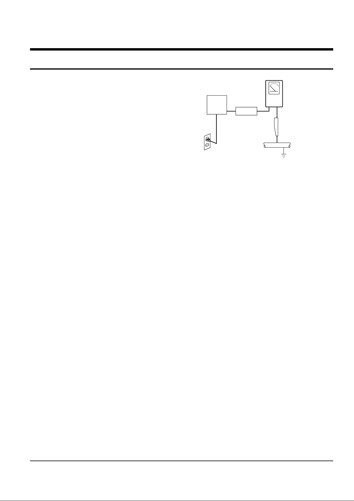
4. Leakage Current Hot Check (See Fig. 1-1) :
Warning : Do not use an isolation transformer
during this test. Use a leakage current tester or a
metering system that complies with American
National Standards Institute (ANSI C101.1,
Leakage Current for Appliances), and Underwriters
Laboratories (UL Publication UL1410, 59.7).
5. With the unit completely reassembled, plug the AC
line cord directly the power outlet. With the unit’s
AC switch first in the ON position and then OFF,
measure the current between a known earth
ground (metal water pipe, conduit, etc.) and all
exposed metal parts, including : antennas, handle
brackets, metal cabinets, screwheads and control
shafts. The current measured should not exceed
0.5 milliamp. Reverse the power-plug prongs in the
AC outlet and repeat the test.
6. X-ray Limits :
The picture tube is designed to prohibit X-ray
emissions. To ensure continued X-ray protection,
replace the picture tube only with one that is the
same type as the original.
Fig. 1-1 AC Leakage Test
7. Antenna Cold Check :
With the unit’s AC plug disconnected from the
AC source, connect an electrical jumper across the
two AC prongs. Connect one lead of the ohmmeter
to an AC prong.
Connect the other lead to the coaxial connector.
8. High Voltage Limit :
High voltage must be measured each time
servicing is done on the B+, horizontal deflection
or high voltage circuits.
Heed the high voltage limits. These include the
X-ray protection Specifications Label, and the
Product Safety and X-ray Warning Note on the
service data schematic.
9. Some semiconductor (“solid state”) devices are
easily damaged by static electricity.
Such components are called Electrostatically
Sensitive Devices (ESDs); examples include
integrated circuits and some field-effect transistors.
The following techniques will reduce the
occurrence of component damage caused by static
electricity.
10. Immediately before handling any semiconductor
components or assemblies, drain the electrostatic
charge from your body by touching a known
earth ground. Alternatively, wear a discharging
Wrist-strap device. (Be sure to remove it prior to
applying power--this is an electric shock
precaution.)
DEVICE
UNDER
TEST
(READING SHOULD
NOT BE ABOVE
0.5mA)
LEAKAGE
CURRENT
TESTER
EARTH
GROUND
TEST ALL
EXPOSED METER
SURFACES
ALSO TEST WITH
PLUG REVERSED
(USING AC ADAPTER
PLUG AS REQUIRED)
2-WIRE CORD

Precautions
1-2 Samsung Electronics
11. High voltage is maintained within specified limits
by close-tolerance, safety-related components and
adjustments. If the high voltage exceeds the
specified limits, check each of the special
components.
12. Design Alteration Warning :
Never alter or add to the mechanical or electrical
design of this unit. Example : Do not add
auxiliary audio or video connectors.
Such alterations might create a safety hazard.
Also, any design changes or additions will void
the manufacturer’s warranty.
13. Hot Chassis Warning :
Some TV receiver chassis are electrically
connected directly to one conductor of the AC
power cord. If an isolation transformer is not
used, these units may be safely serviced only if
the AC power plug is inserted so that the chassis
is connected to the ground side of the AC source.
To confirm that the AC power plug is inserted
correctly, do the following : Using an AC
voltmeter, measure the voltage between the
chassis and a known earth ground. If the reading
is greater than 1.0V, remove the AC power plug,
reverse its polarity and reinsert. Re-measure the
voltage between the chassis and ground.
14. Some TV chassis are designed to operate with 85
volts AC between chassis and ground, regardless
of the AC plug polarity. These units can be safely
serviced only if an isolation transformer inserted
between the receiver and the power source.
15. Never defeat any of the B+ voltage interlocks.
Do not apply AC power to the unit (or any of its
assemblies) unless all solid-state heat sinks are
correctly installed.
16. Always connect a test instrument’s ground lead to
the instrument chassis ground before connecting
the positive lead; always remove the instrument’s
ground lead last.
17. Observe the original lead dress, especially near
the following areas : Antenna wiring, sharp
edges, and especially the AC and high voltage
power supplies. Always inspect for pinched, outof-place, or frayed wiring. Do not change the
spacing between components and the printed
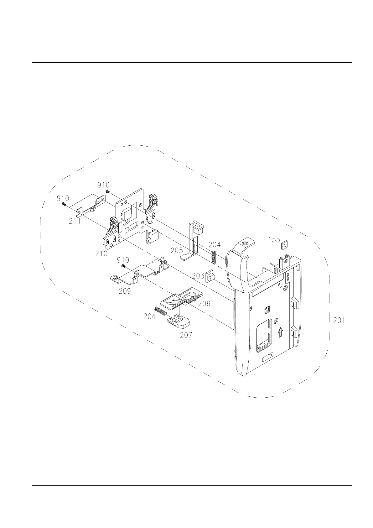
circuit board. Check the AC power cord for
damage. Make sure that leads and components
do not touch thermally hot parts.
18. Picture Tube Implosion Warning :
The picture tube in this receiver employs
“integral implosion” protection. To ensure
continued implosion protection, make sure that
the replacement picture tube is the same as the
original.
19. Do not remove, install or handle the picture tube
without first putting on shatterproof goggles
equipped with side shields. Never handle the
picture tube by its neck. Some “in-line” picture
tubes are equipped with a permanently attached
deflection yoke; do not try to remove such
“permanently attached” yokes from the picture
tube.
20. Product Safety Notice :
Some electrical and mechanical parts have special
safety-related characteristics which might not be
obvious from visual inspection. These safety
features and the protection they give might be
lost if the replacement component differs from the
original--even if the replacement is rated for
higher voltage, wattage, etc.
Components that are critical for safety are
indicated in the circuit diagram by shading,
( or ).
Use replacement components that have the same
ratings, especially for flame resistance and
dielectric strength specifications. Areplacement
part that does not have the same safety
characteristics as the original might create shock,
fire or other hazards.

2-1 Ass’y Lens/Deck - - - - - - - - - - - - - - - - - - - - - - - - - - - - - - - - - - - - - - - - - - - 2-2
2-2 Ass’y EVF/CVF - - - - - - - - - - - - - - - - - - - - - - - - - - - - - - - - - - - - - - - - - - - - 2-4
2-3 Ass’y Front - - - - - - - - - - - - - - - - - - - - - - - - - - - - - - - - - - - - - - - - - - - - - - 2-6
2-4 Ass’y LCD - - - - - - - - - - - - - - - - - - - - - - - - - - - - - - - - - - - - - - - - - - - - - - - 2-8
2-5 Ass’y Left - - - - - - - - - - - - - - - - - - - - - - - - - - - - - - - - - - - - - - - - - - - - - - - 2-10
2-6 Ass’y Cover Housing- - - - - - - - - - - - - - - - - - - - - - - - - - - - - - - - - - - - - - - - 2-12
2-7 Ass’y Rear- - - - - - - - - - - - - - - - - - - - - - - - - - - - - - - - - - - - - - - - - - - - - - - 2-14
2-8 Ass’y Right - - - - - - - - - - - - - - - - - - - - - - - - - - - - - - - - - - - - - - - - - - - - - - 2-16
2-9 Mechanical Parts (1) (Main Chassis)- - - - - - - - - - - - - - - - - - - - - - - - - - - - - 2-18
2-10 Mechanical Parts (2) (Sub Chassis)- - - - - - - - - - - - - - - - - - - - - - - - - - - - - 2-20
Page
Exploded View and Parts List
2-1Samsung Electronics
2. Exploded View and Parts List
You can search for the updated part code through ITSELF web site.
URL; http://itself.sec.samsung.co.kr
Notice
Exploded View and Parts List
2-2 Samsung Electronics
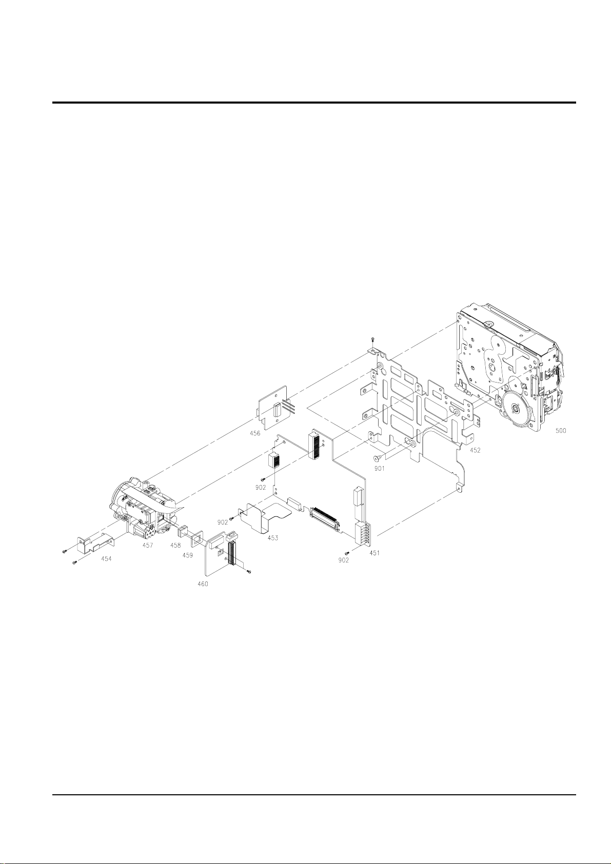
2-1 Ass’y Lens/Deck

Exploded View and Parts List
2-3Samsung Electronics
Loc. No Parts No. Description ; Specification Remark
451 AD97-07502C ASSY-MAIN BOARD;-,VP-D30/XEU,THETA-PJ
452 AD97-06882A ASSY-CHASSIS DECK;ASSY,THETA-PJ,453 AD63-00487A SHIELD-CASE FPC;THETA-PJ,SPTE,T0.25,50,3
454 AD61-01287A BRACKET-LENS;THETA-PJ,SUS,T0.5,-,-,-,456 AD97-06757A ASSY-FRONT BOARD;THETA-PJ,-,457 AD97-04747A ASSY-LENS;-,DVC10X,SUML
458 AD29-00019A FILTER-OPTICAL LPF;-,VP-D73,-,-,3.4X4.5X
459 AD60-00053A SPACER-CCD;ALPHA_PJ,SILICON,-,-,-,BLK,-,
460 AD97-06496A ASSY-CCD;,THETA-PJ,THETA,ASSY-CCD,PAL
500 AD97-04896A ASSY-DECK;-,CSM2000,ALPA,BETA
901 6009-001284 SCREW-SPECIAL;SWRCH18A,-,CH,+,M1.4,L4.7(
902 6001-001526 SCREW-MACHINE;CH(0.3),+,M1.7,L3.0,NI PLT
Exploded View and Parts List
2-4 Samsung Electronics
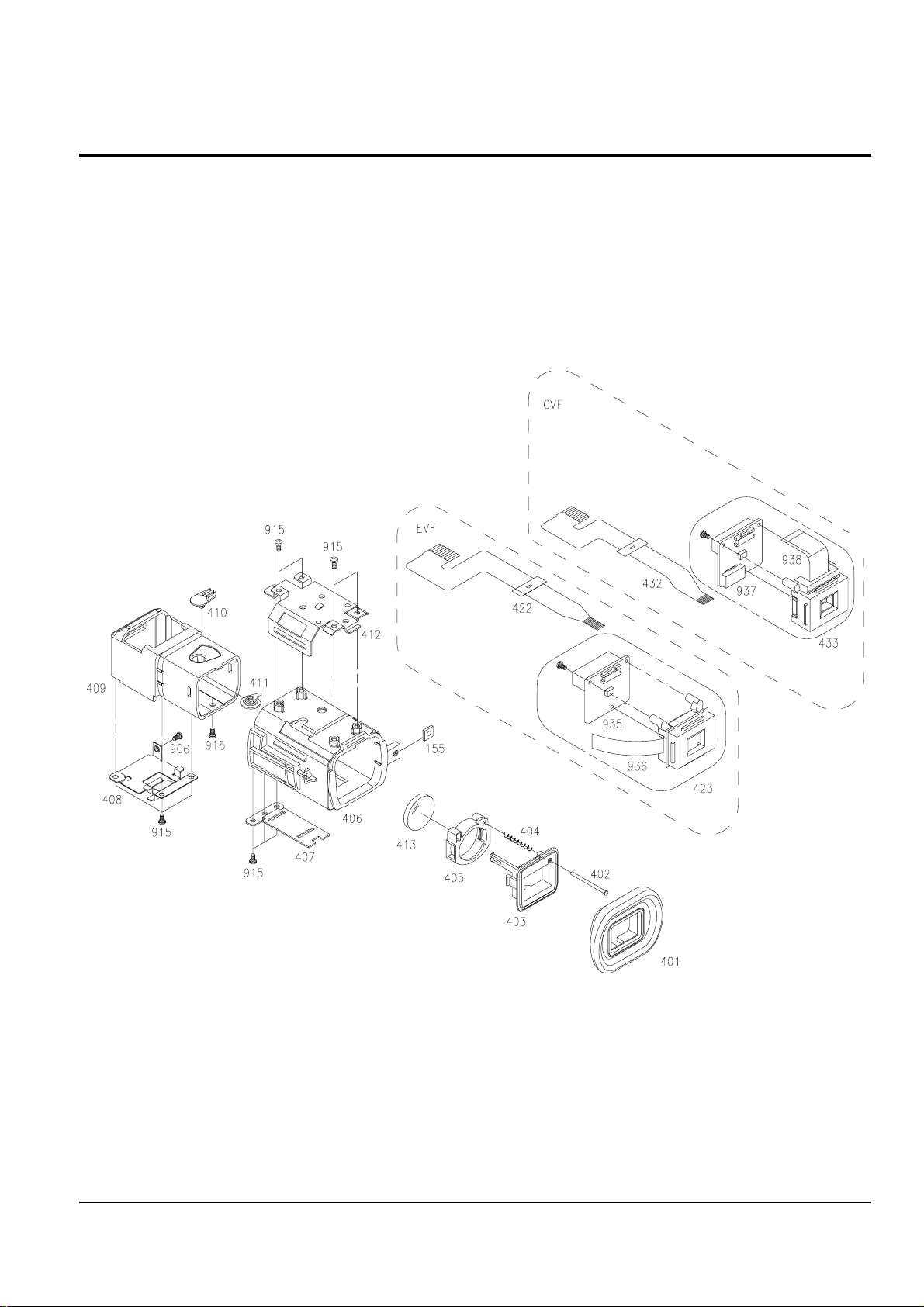
2-2 Ass’y EVF/CVF

Exploded View and Parts List
2-5Samsung Electronics
Loc. No Parts No. Description ; Specification Remark
155 AD61-12033A BRACKET-NUT;SV-D10,T0.8,-,-,-,-,T0.8
401 AD73-00094B RUBBER-EYE CUP;THETA-PJ,SILICON,-,-,-,D/
402 AD66-00233A SHAFT-EVF LENS;THETA-PJ,SUS,-,-,-,-,403 AD63-00451B COVER-EYE CUP;THETA-PJ,PC,-,-,-,-,-,G358
404 AD61-01300A SPRING ETC-EVF LENS;-,SWPB,-,-,-,-,-,T0.
405 AD61-01302A HOLDER-EVF LENS;THETA-PJ,ABS,-,-,-,-,406 AD64-01017A CASE-EVF BODY;THETA-PJ,PC/ABS,-,-,-,-,-,
408 AD61-01288A BRACKET-EVF SLIDE;THETA-PJ,SUS,T0.3,-,-,
407 AD61-01290A BRACKET-EVF STOPPER;THETA-PJ,SUS304,T0.5
409 AD64-01016B CABINET-EVF SLIDER;THETA-PJ,PC,-,-,-,-,G
411 AD64-01019A KNOB-EVF ROTATION;THETA-PJ,POM,-,-,-,-,410 AD64-01018B KNOB-EVF;THETA-PJ,ABS 94HB,-,-,-,-,G358
412 AD61-01384A BRACKET-EVF TOP;THETA-PJ,SUS304,T0.5,-,413 AD67-00194A LENS-EVF 14X G1;DELTA-PJ,OPT PLASTIC PMM
422 AD41-00402A FPC-EVF;THETA-PJ,POLYESTER,1,00,0.3,83
423 AD97-07159A ASSY-UNIT-EVF;0.24PAL,DELTA-PJ,UNIT-EVF
906 6001-001444 SCREW-MACHINE;PH,+,M1.7,L2.0,ZPC(BLK),SW
915 6003-001292 SCREW-TAPTITE;CH(0.3),+,B,M1.7,L3.0,ZPC(
935 AD97-06506B ASSY-EVF BOARD(PAL);DVC,VP-D26,EVF BOARD
936 AD07-00009A LCD-PANNEL;-,MCVVQ410(320),VP-D50,0.24IN
Exploded View and Parts List
2-6 Samsung Electronics
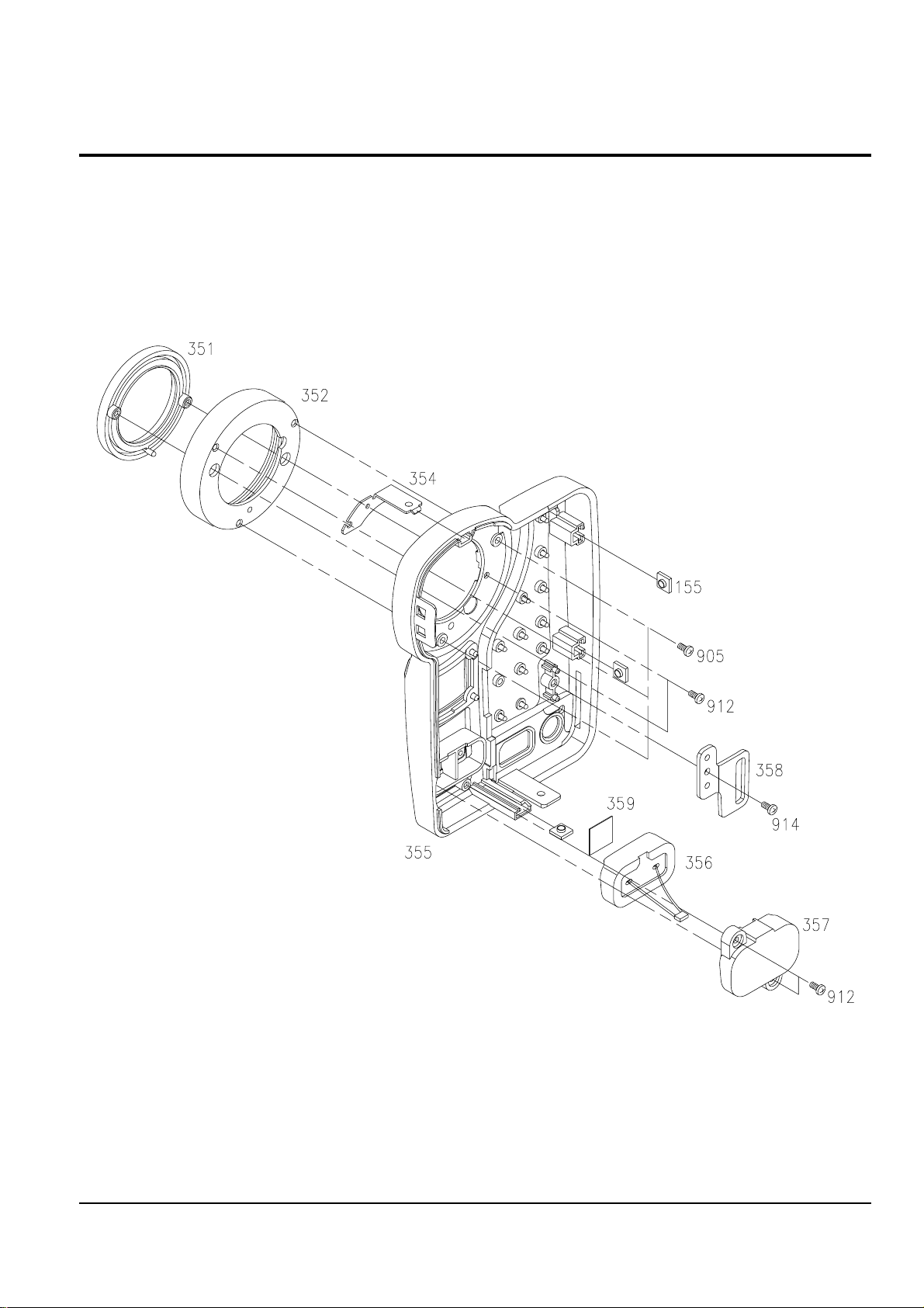
2-3 Ass’y Front

Exploded View and Parts List
2-7Samsung Electronics
Loc. No Parts No. Description ; Specification Remark
155 AD61-12033A BRACKET-NUT;SV-D10,T0.8,-,-,-,-,T0.8
351 AD61-01294A HOLDER-HOOD;THETA-PJ,ABS 94HB,-,-,-,-,352 AD67-00215A LENS-HOOD;THETA-PJ,CU,-,-,-,-,354 AD61-01305A BRACKET-FRONT;THETA-PJ,SUS304,-,-,-,-,355 AD64-01008A CASE-FRONT;THETA-PJ,ABS 94HB,-,-,-,-,G62
356 AD97-06753A ASSY-MIC;,THETA-PJ,MIC ASSY
357 AD63-00443A COVER-MIC;THETA-PJ,ABS 94HB,-,-,-,-,-,-,
358 AD61-01306A BRACKET-GRIP FRONT;THETA-PJ,SUS304,-,-,359 AD63-00455A SHEET-MIC;THETA-PJ,-,T0.5,-,-,-,905 6001-000803 SCREW-MACHINE;CH,+,M1.4,L4,ZPC(BLK),SWRC
912 6003-001291 SCREW-TAPTITE;CH,+,B,M1.4,L3.0,ZPC(BLK),
914 6003-001245 SCREW-TAPTITE;PH,+,B,M1.7,L3.5,NI PLT,SW
Exploded View and Parts List
2-8 Samsung Electronics
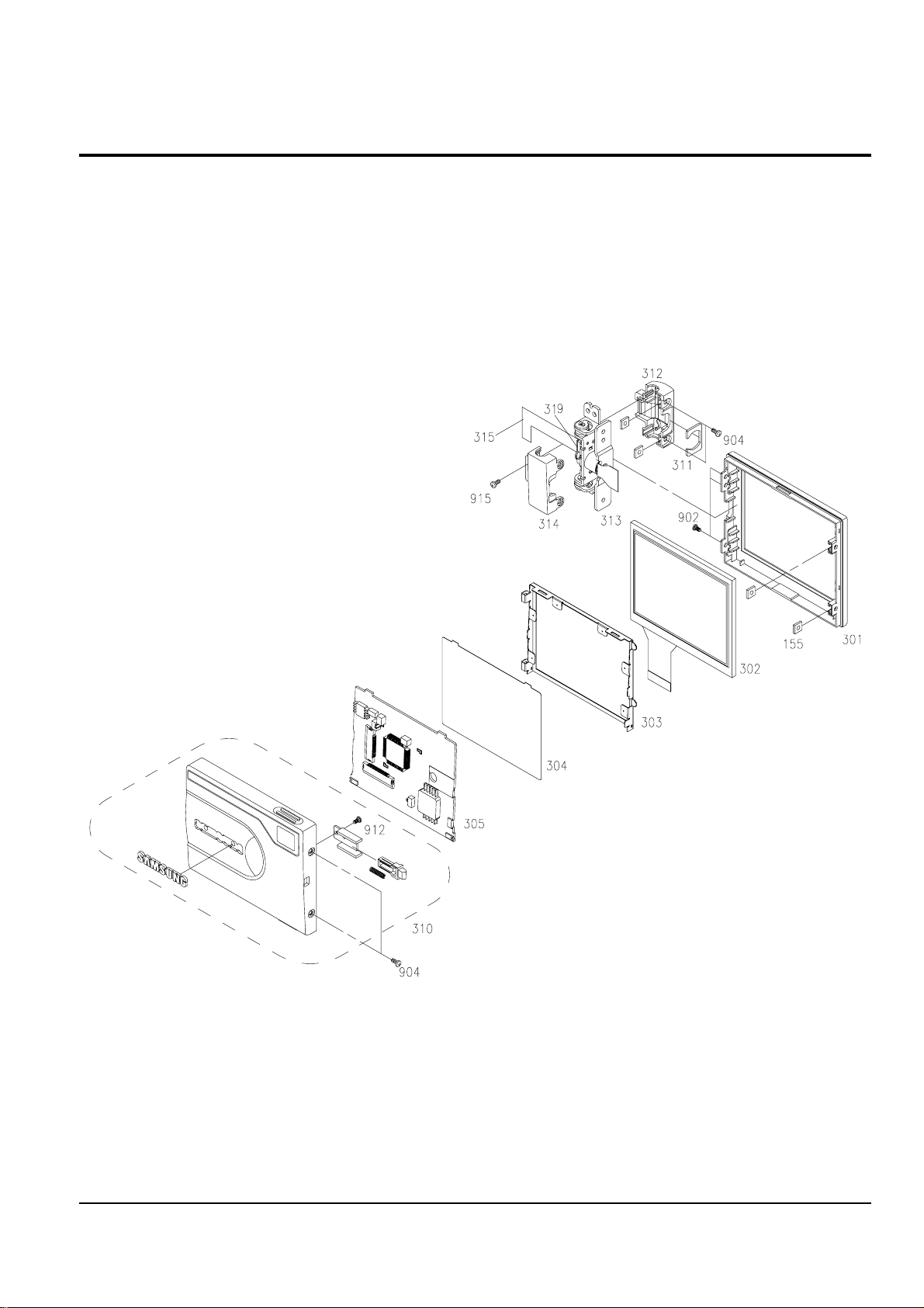
2-4 Ass’y LCD

Exploded View and Parts List
2-9Samsung Electronics
Loc. No Parts No. Description ; Specification Remark
155 AD61-12033A BRACKET-NUT;SV-D10,T0.8,-,-,-,-,T0.8
301 AD64-01011A CASE-LCD BOTTOM;THETA-PJ,PC,-,-,-,-,-,302 AD07-00037A LCD-PANEL;ACX307AKA,THETA-PJ,-,55*74*46.
303 AD97-06883A ASSY-BL;2.5,3T,THETA-PJ,THETA-BL
304 AD62-00031A INSULATION;THETA-PJ,BE-CU,-,-,-,-,-,-,305 AD97-06619A ASSY-LCD BOARD;-,THETA-PJ,THETA,LCD
310 AD97-07464A ASSY-CASE LCD;ASSY,VP-D30,PAL
311 AD63-00291A COVER-SLIDE;D5-PJ,POLYSLIDE T0.8,-,-,-,312 AD63-00447A COVER-HINGE BOTTOM;THETA-PJ,ABS,-,-,-,-,
313 AD97-06877A ASSY-HINGE;-,THETA-PJ,314 AD63-00449A COVER-HINGE TOP;THETA-PJ,ABS,-,-,-,-,-,315 AD97-06878A ASSY-LCD FPC;-,THETA-PJ,319 AD61-00816A HOLDER-INVERT;D5-PJ,PC GLASS 30%,-,-,-,902 6001-001526 SCREW-MACHINE;CH(0.3),+,M1.7,L3.0,NI PLT
904 6001-001527 SCREW-MACHINE;CH(0.3),+,M1.7,L2.0,NI PLT
912 6003-001291 SCREW-TAPTITE;CH,+,B,M1.4,L3.0,ZPC(BLK),
915 6002-001132 SCREW-TAPPING;BH,T0.5,+,2,M1.7,L3.0,BLK,
Exploded View and Parts List
2-10 Samsung Electronics
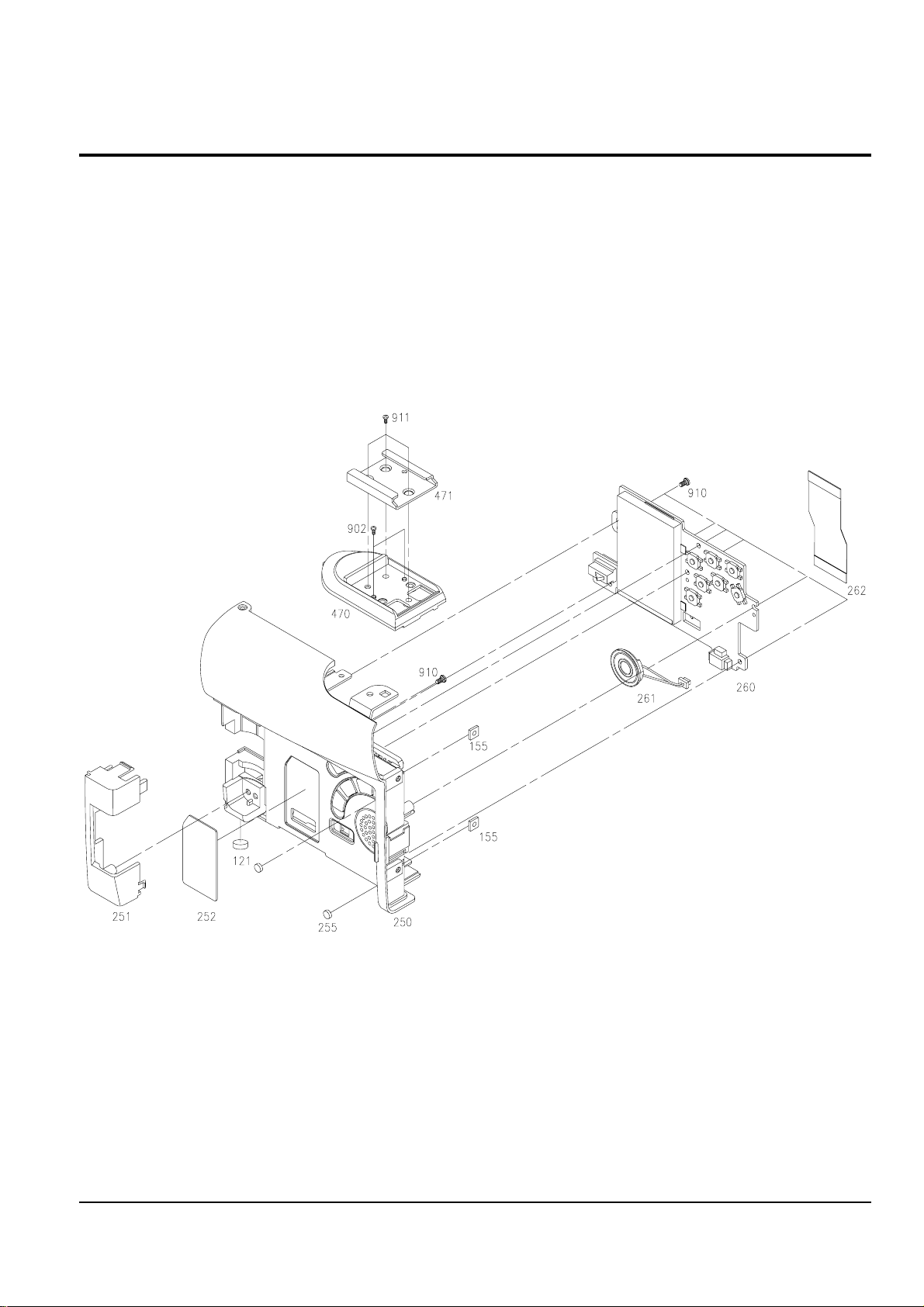
2-5 Ass’y Left

Exploded View and Parts List
2-11Samsung Electronics
Loc. No Parts No. Description ; Specification Remark
121 AD69-00454A PAD-LEG;THETA-PJ,T0.9,PI 4,
155 AD61-12033A BRACKET-NUT;SV-D10,T0.8,-,-,-,-,T0.8
250 AD97-07012A ASSY-CASE LEFT;ASSY,THETA-PJ,EXP,MS-NOTH
251 AD63-00439A COVER-LEFT;THETA-PJ,ABS,-,-,-,-,-,G4092B
252 AD64-01009B INLAY-M/S;THETA-PJ,PC,T0.9,-,-,-,NON M/S
255 AD69-00263B PAD-HOUSING;D5-PJ,PORON(HH-48)L/GRAY,T0.
260 AD97-06961A ASSY-FUNCTION BOARD;THETA-PJ,-,DSC(X)
261 AD97-04289A ASSY-SPEAKER;-,D5-PJ,G-17S08-0823
262 AD97-06955A ASSY-FUNCTION FPC;ASSY,THETA-PJ,470 AD63-00438A COVER-TOP;THETA-PJ,ABS 94HB,-,-,-,-,-,G6
471 AD61-01385A BRACKET-ACC SHOE;THETA-PJ,SUS304,T0.8,-,
902 6001-001526 SCREW-MACHINE;CH(0.3),+,M1.7,L3.0,NI PLT
910 6003-001453 SCREW-TAPTITE;BH,+,B,M1.7,L4,ZPC(BLK)
911 6003-001445 SCREW-TAPTITE;PH,+,B,M2,L5,ZPC(BLK)
Exploded View and Parts List
2-12 Samsung Electronics
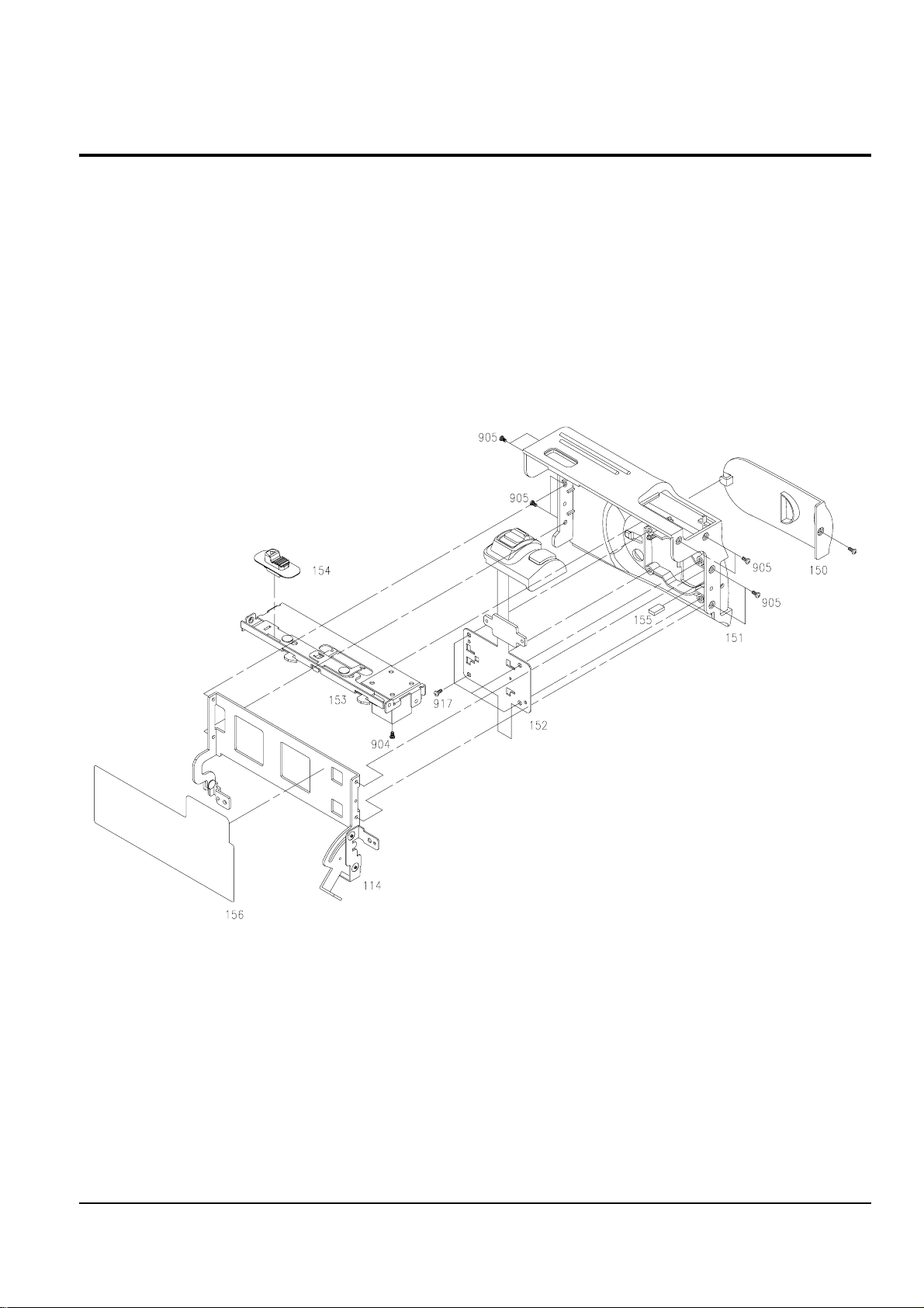
2-6 Ass’y Cover Housing

Exploded View and Parts List
2-13Samsung Electronics
Loc. No Parts No. Description ; Specification Remark
114 AD97-06875A ASSY-LINK HOUSING BOTTOM;-,THETA-PJ,150 AD63-00457A COVER-DUMMY HOUSING;THETA-PJ,ABS,-,-,-,151 AD63-00458C COVER-HOUSING;THETA-PJ,ABS 94HB,-,-,-,-,
152 AD97-06772A ASSY-ZOOM;ABS 94HB,THETA-PJ,153 AD97-06874A ASSY-LINK HOUSING TOP;-,THETA-PJ,154 AD64-01026A KNOB-TAPE EJECT;THETA-PJ,ABS,-,-,-,-,-,155 AD61-12033A BRACKET-NUT;SV-D10,T0.8,-,-,-,-,T0.8
156 AD63-00483A SHEET-HOUSING;THETA-PJ,PVC,T0.2,-,-,-,904 6001-001527 SCREW-MACHINE;CH(0.3),+,M1.7,L2.0,NI PLT
905 6001-000803 SCREW-MACHINE;CH,+,M1.4,L4,ZPC(BLK),SWRC
917 6003-001292 SCREW-TAPTITE;CH(0.3),+,B,M1.7,L3.0,ZPC(
Exploded View and Parts List
2-14 Samsung Electronics
2-7 Ass’y Rear
 Loading...