

Samsung UN50JU7100F, UN60JU7100F, UN65JU7100F, UN40JU7100F, UN55JU7100F Service Manual
...
UHD TV
SERVICE
Manual
UHD TV Contents
1. Precautions
2. Product specications
3. Disassembly and Reassembly
4. Troubleshooting
5. Wiring Diagram
UN**JU7100F
Chassis : UWJ50
Model : UN40JU7100F
UN50JU7100F
UN55JU7100F
UN60JU7100F
UN65JU7100F
UN75JU7100F

Contents
1. Precautions .............................................................................................................. 1-1
1-1. Safety Precautions ......................................................................................................... 1-1
1-1-1. Warnings .............................................................................................................. 1-1
1-1-2. Servicing the LED TV ...........................................................................................1-1
1-1-3. Fire and Shock Hazard ........................................................................................ 1-1
1-1-4. Product Safety Notices ........................................................................................ 1-2
1-2. Servicing Precautions ..................................................................................................... 1-3
1-2-1. General Servicing Precautions ............................................................................ 1-3
1-3. Static Electricity Precautions .......................................................................................... 1-4
1-4. Installation Precautions .................................................................................................. 1-5
2. Product Specications............................................................................................ 2-1
2-1. Product information ........................................................................................................ 2-1
2-2. Product specication ..................................................................................................... 2-3
2-2-1. Feature & Specications ...................................................................................... 2-3
2-2-2. Detailed Specications ......................................................................................... 2-4
2-3. Accessories .................................................................................................................... 2-8
2-4. Viewing the Functions ..................................................................................................... 2-9
2-5. NEW Key Features ....................................................................................................... 2-11
2-5-1. 15" New UI ......................................................................................................... 2-11
2-5-2. Multi Screen ....................................................................................................... 2-12
2-5-3. Instant On .......................................................................................................... 2-13
2-6. HDMI 60P Mode ........................................................................................................... 2-14
2-7. Supported Formats ....................................................................................................... 2-15
3. Disassembly and Reassembly ............................................................................... 3-1
3-1. Disassembly and Reassembly ....................................................................................... 3-1
3-1-1. TV Disassembly ................................................................................................... 3-1
3-1-2. One Connect MINI ............................................................................................... 3-5
4. Troubleshooting ...................................................................................................... 4-1
4-1. Troubleshooting .............................................................................................................. 4-1
4-1-1. Previous Check .................................................................................................... 4-1
4-2. How to Check Fault Symptom ........................................................................................ 4-3
4-2-1. Video .................................................................................................................... 4-3
4-2-2. Bluetooth / WIFI Module ...................................................................................... 4-5
4-2-3. One Connect Mini ................................................................................................ 4-9
4-2-4. Apps / Photos, Videos & Music ..........................................................................4-10
4-3. Factory Mode Adjustments ........................................................................................... 4-11
4-3-1. Detail Factory Option ......................................................................................... 4-11
4-3-2. Entering Factory Mode ....................................................................................... 4-13
4-3-3. Factory Data ...................................................................................................... 4-14

4-4. White Balance .............................................................................................................. 4-22
4-4-1. Calibration .......................................................................................................... 4-22
4-4-2. Service Adjustment ............................................................................................ 4-22
4-4-3. Adjustment ......................................................................................................... 4-24
4-5. RS-232C ....................................................................................................................... 4-25
4-6. AV Control Tabe ............................................................................................................ 4-26
4-7. Updating the TV’s Software .......................................................................................... 4-32
5. Wiring Diagram ........................................................................................................ 5-1
5-1. Wiring Diagram ............................................................................................................... 5-1
5-2. Connector ....................................................................................................................... 5-3
ANNEX. Exploded View & Part List [UN40JU7100FXZA-TS01] .....................ANNEX-1
1-1. Exploded View ......................................................................................................ANNEX-1
1-1-1. Parts List ....................................................................................................ANNEX-2
2-1. Electrical Parts List ...............................................................................................ANNEX-3
ANNEX. Exploded View & Part List [UN50JU7100FXZA-IS01] ......................ANNEX-1
1-1. Exploded View ......................................................................................................ANNEX-1
1-1-1. Parts List ....................................................................................................ANNEX-2
2-1. Electrical Parts List ...............................................................................................ANNEX-3
ANNEX. Exploded View & Part List [UN55JU7100FXZA-TS01] .....................ANNEX-1
1-1. Exploded View ......................................................................................................ANNEX-1
1-1-1. Parts List ....................................................................................................ANNEX-2
2-1. Electrical Parts List ...............................................................................................ANNEX-3
ANNEX. Exploded View & Part List [UN60JU7100FXZA-MH01] ....................ANNEX-1
1-1. Exploded View ......................................................................................................ANNEX-1
1-1-1. Parts List ....................................................................................................ANNEX-2
2-1. Electrical Parts List ...............................................................................................ANNEX-3
ANNEX. Exploded View & Part List [UN65JU7100FXZA-TH01] .....................ANNEX-1
1-1. Exploded View ......................................................................................................ANNEX-1
1-1-1. Parts List ....................................................................................................ANNEX-2
2-1. Electrical Parts List ...............................................................................................ANNEX-3
ANNEX. Exploded View & Part List [UN75JU7100FXZA-TS01] .....................ANNEX-1
1-1. Exploded View ......................................................................................................ANNEX-1
1-1-1. Parts List ....................................................................................................ANNEX-2
2-1. Electrical Parts List ...............................................................................................ANNEX-3

This Service Manual is a property of Samsung Electronics Co.,Ltd.
Any unauthorized use of Manual can be punished under applicable
International and/or domestic law.
© 2015 Samsung Electronics Co.,Ltd.
All rights reserved.
Printed in Korea
Follow these safety, servicing and ESD precautions to prevent damage and to protect against potential hazards such as
electrical shock.
1-1-1. Warnings
WARNING
For continued safety, do not attempt to modify the circuit board.
Disconnect the AC power and DC power jack before servicing.
1-1-2. Servicing the LED TV
When servicing the LED TV, Disconnect the AC line cord from the AC outlet.1.
It is essential that service technicians have an accurate voltage meter available at all times. Check the calibration of this 2.
meter periodically.
1-1-3. Fire and Shock Hazard
Before returning the monitor to the user, perform the following safety checks:
Inspect each lead dress to make certain that the leads are not pinched or that hardware is not lodged between the 1.
chassis and other metal parts in the monitor.
Inspect all protective devices such as nonmetallic control knobs, insulating materials, cabinet backs, adjustment and 2.
compartment covers or shields, isolation resistorcapacitor networks, mechanical insulators, etc.
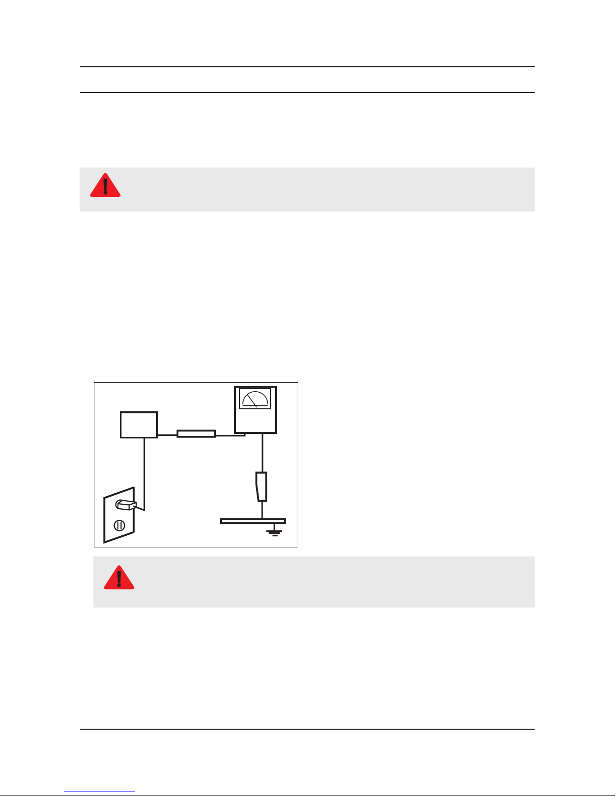
Leakage Current Hot Check:3.
DEVICE
UNDER
TEST
(READING SHOULD)
NOT BE ABOVE 0.5mA
LEAKAGE
CURRENT
TESTER
TEST ALL
EXPOSED METAL
SURFACES
2-WIRE CORD
ALSO TEST WITH
PLUG REVERSED
(USING AC ADAPTER
PLUG AS REQUIRED)
EARTH
GROUND
WARNING
Do not use an isolation transformer during this test.
Use a leakage current tester or a metering system that complies with American National Standards
Institute (ANSI C101.1, Leakage Current for Appliances), and Underwriters Laboratories (UL
Publication UL1410, 59.7).
With the unit completely reassembled, plug the AC line cord directly into a 120V AC outlet. With the unit’s AC switch rst 4.
in the ON position and then OFF, measure the current between a known earth ground (metal water pipe, conduit, etc.)
and all exposed metal parts, including: metal cabinets, screwheads and control shafts.
The current measured should not exceed 0.5 milliamp.
Reverse the power-plug prongs in the AC outlet and repeat the test.
1-1
1. Precautions
1. Precautions
1-1. Safety Precautions

1-2
1. Precautions
1-1-4. Product Safety Notices
Some electrical and mechanical parts have special safetyrelated characteristics which are often not evident from visual
inspection. The protection they give may not be obtained by replacing them with components rated for higher voltage,
wattage, etc. Parts that have special safety characteristics are identied by on schematics and parts lists. A substitute
replacement that does not have the same safety characteristics as the recommended replacement part might create
shock, re and/or other hazards. Product safety is under review continuously and new instructions are issued whenever
appropriate.
WARNING
An electrolytic capacitor installed with the wrong polarity might explode.
CAUTION
Before servicing units covered by this service manual, read and follow the Safety Precautions section of
this manual.
NOTE
If unforeseen circumstances create conict between the following servicing precautions and any of the
safety precautions, always follow the safety precautions.
1-2-1. General Servicing Precautions
Always unplug the unit’s AC power cord from the AC power source and disconnect the DC Power Jack before 1.
attempting to: (a) remove or reinstall any component or assembly, (b) disconnect PCB plugs or connectors, (c) connect
a test component in parallel with an electrolytic capacitor.
Some components are raised above the printed circuit board for safety. An insulation tube or tape is sometimes used. 2.
The internal wiring is sometimes clamped to prevent contact with thermally hot components. Reinstall all such elements
to their original position.
After servicing, always check that the screws, components and wiring have been correctly reinstalled. Make sure that 3.
the area around the serviced part has not been damaged.
Check the insulation between the blades of the AC plug and accessible conductive parts (examples: metal panels, input 4.
terminals and earphone jacks).
Insulation Checking Procedure: Disconnect the power cord from the AC source and turn the power switch ON. Connect 5.
an insulation resistance meter (500 V) to theblades of the AC plug. The insulation resistance between each blade of the
AC plug and accessible conductive parts (see above) should be greater than 1 megohm.
Always connect a test instrument’s ground lead to the instrument chassis ground before connecting the positive lead; 6.
always remove the instrument’s ground lead last.
1-3
1. Precautions
1-2. Servicing Precautions
Some semiconductor (solid state) devices can be easily damaged by static electricity. Such components are commonly
called Electrostatically Sensitive Devices (ESD). Examples of typical ESD are integrated circuits and some eld-effect
transistors. The following techniques will reduce the incidence of component damage caused by static electricity.
Immediately before handling any semiconductor components or assemblies, drain the electrostatic charge from your 1.
body by touching a known earth ground. Alternatively, wear a discharging wrist-strap device. To avoid a shock hazard,
be sure to remove the wrist strap before applying power to the monitor.
After removing an ESD-equipped assembly, place it on a conductive surface such as aluminum foil to prevent 2.
accumulation of an electrostatic charge.
Do not use freon-propelled chemicals. These can generate electrical charges sufcient to damage ESDs.3.
Use only a grounded-tip soldering iron to solder or desolder ESDs.4.
Use only an anti-static solder removal device. Some solder removal devices not classied as “anti-static” can generate 5.
electrical charges sufcient to damage ESDs.
Do not remove a replacement ESD from its protective package until you are ready to install it. Most replacement ESDs 6.
are packaged with leads that are electrically shorted together by conductive foam, aluminum foil or other conductive
materials.
Immediately before removing the protective material from the leads of a replacement ESD, touch the protective material 7.
to the chassis or circuit assembly into which the device will be installed.
CAUTION
Be sure no power is applied to the chassis or circuit and observe all other safety precautions.
Minimize body motions when handling unpackaged replacement ESDs. Motions such as brushing clothes together, or 8.
lifting your foot from a carpeted oor can generate enough static electricity to damage an ESD.
1-4
1. Precautions
1-3. Static Electricity Precautions
For safety reasons, more than a people are required for carrying the product.1.
Keep the power cord away from any heat emitting devices, as a melted covering may cause re or electric shock.2.
Do not place the product in areas with poor ventilation such as a bookshelf or closet. The increased internal temperature 3.
may cause re.
Bend the external antenna cable when connecting it to the product. This is a measure to protect it from being exposed 4.
to moisture. Otherwise, it may cause a re or electric shock.
Make sure to turn the power off and unplug the power cord from the outlet before repositioning the product. Also check 5.
the antenna cable or the external connectors if they are fully unplugged. Damage to the cord may cause re or electric
shock.
Keep the antenna far away from any high-voltage cables and install it rmly. Contact with the highvoltage cable or the 6.
antenna falling over may cause re or electric shock.
When installing the product, leave enough space (0.4m) between the product and the wall for ventilation purposes. 7.
A rise in temperature within the product may cause re.
If an equipment is provided with a replaceable battery, and if replacement by an incorrect type could result in an 8.
explosion (for example, with some lithium batteries), the following applies:
CAUTION
Risk of explosion if battery is replaced by an incorrect type dispose of used batteries according to •
the instructions.
Do not dispose of batteries in a re.•
Do not short circuit, disassemble or overheat the batteries.•
Danger of explosion if battery is incorrectly replaced. Replace only with the same or equivalent •
type.
Do not be exposed to excessive heat such as sunshine, re or the like.•
1-5
1. Precautions
1-4. Installation Precautions
2-1
2. Product specications
2. Product Specications
2-1. Product information
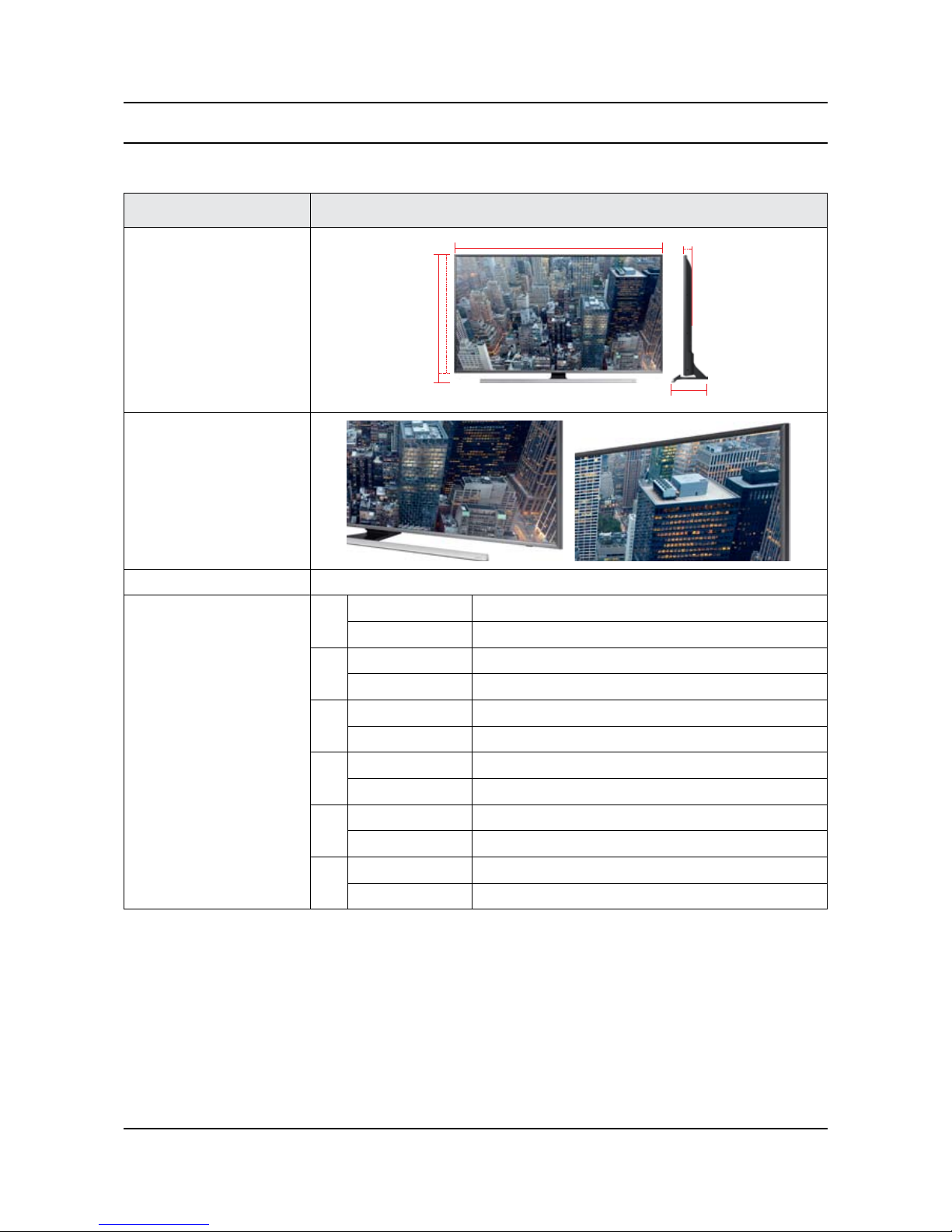
Model UN**JU7100F
Front View
W
D
* W : Width H : High D : Depth
H
Detail View
Front Color Black
Dimensions
(W x H x D)
40"
Body 917.7 X 535.6 X 66.8 mm
With stand 917.7 X 587.7 X 271.7 mm
50"
Body 1128.8 X 654.3 X 67.4 mm
With stand 1128.8 X 706.8 X 277.7 mm
55"
Body 1242.6 X 718.3 X 67.4 mm
With stand 1242.6 X 770.5 X 277.7 mm
60"
Body 1363.6 X 789.3 X 68.2 mm
With stand 1363.6 X 838.9 X 295.1 mm
65"
Body 1463.4 X 844.2 X 68.8 mm
With stand 1463.4 X 897.0 X 295.1 mm
75"
Body 1688.8 X 971.0 X 70.2 mm
With stand 1688.8 X 1035.8 X 325.0 mm
2-2
2. Product specications
Model UN**JU7100F
Weight
40"
Body 8.3 Kg
With stand 10.4 Kg
50"
Body 12.5 Kg
With stand 15.3 Kg
55"
Body 15.4 Kg
With stand 18.2 Kg
60"
Body 21.4 Kg
With stand 25.6 Kg
65"
Body 23.9 Kg
With stand 28.1 Kg
75"
Body 37.2 Kg
With stand 42.9 Kg
Panel Type Ultra Clear Pro
Internal Memory 8GB
DDR DDR3 2.5GB
Feature Media Play (Movie, Photo, Music)
2-3
2. Product specications
2-2. Product specication
2-2-1. Feature & Specications
Feature
UHD TV, RF, 4-HDMI, 1-COMPONENT, 1-A/B(COMMON USE FOR COMPONENTY), 2-USB2.0, 1-USB3.0, •
HEADPHONE
Brightness : 237nit (cd/m•
2)
Specications
Model UN**JU7100F
Item Description
Screen Size (Diagonal) 40 inches 50 inches 55 inches 60 inches 65 inches 75 inches
LCD Panel UHD 120Hz
Scanning Frequency Horizontal : 60 kHz ~ 73 kHz (Automatic)
Vertical : 47 Hz ~ 63 Hz (Automatic)
Display Colors 16.7M color
Display Resolution 3840 X 2160
Input Signal Analog 0.7 Vp-p ± 5% positive at 75Ω, internally terminated
Input Sync Signal H/V Separate, TTL, P. or N.
Maximum Pixel Clock Rate 74.25MHz
AC Power Voltage & Frequency AC110-120V 60Hz
Environmental Considerations Operating Temperature : 50˚F ~ 104˚F (10˚C ~ 40˚C)
Operating Humidity : 10% ~ 80%, non-condensing
Storage Temperature : -4˚F ~ 113˚F (-20˚C ~ 45˚C)
Storage Humidity : 5% ~ 95%, non-condensing
Sound (Output) 20 W
Note : Dolby Digital Plus/Pulse, USB2.0/3.0, Film mode, Energy Saving
2-4
2. Product specications
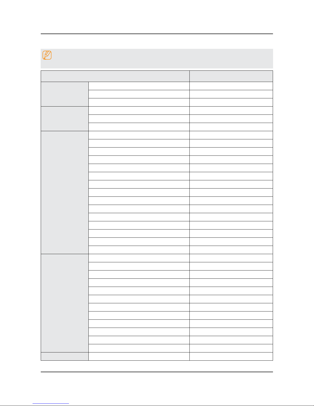
2-2-2. Detailed Specications
NOTE
Design and specications are subject to change without prior notice.
Item UN**JU7100FXZA
General Information
Product UHD
Series 7
Country UNITED STATES
Display
Inch 40" / 50" / 55" / 60" / 65" / 75"
Resolution 3,840 x 2,160
Ultra Clear Panel Ultra Clear Pro
Video
Picture Engine UHD Upscaling
Clear Motion Rate 1200
Motion Refresh Rate 240Hz
Dynamic Contrast Ratio Mega Contrast
Micro Dimming UHD Dimming
Precision Black (Local Dimming) Precision Black
Nano Crystal Color N/A
Wide Color Enhancer (Plus) Yes
PurColor Yes
Auto Depth Enhancer N/A
Contrast Enhancer Yes
Auto Motion Plus Yes
Film Mode Yes
Natural Mode Support Yes
Peak Illuminator Peak Illuminator
Audio
Dolby Digital Plus Yes(MS11)
Virtual Surround DTS Studio Sound
DTS Codec DTS Premim Sound 5.1
3D Sound Yes
Sound Customizer N/A
Sound Output (RMS) 20W
Speaker Type 1way-1spk Down Firing
Woofer N/A
HD Audio Yes
Wallmount Sound Mode Yes
Multiroom Link Yes
TV SoundConnect Yes
Smart TV
Samsung SMART TV Yes
2-5
2. Product specications
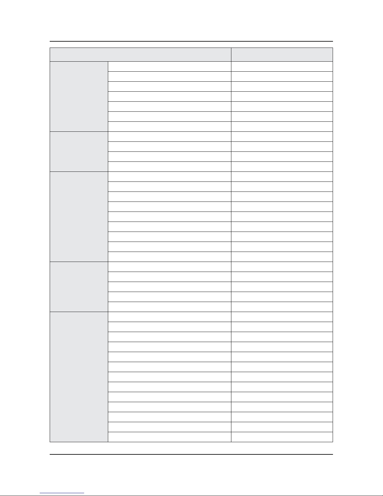
Item UN**JU7100FXZA
Smart TV
Apps Yes
Game Yes
Soccer App N/A
Multi-Link Screen Yes
ACR (Advertisement) Yes
Info Widget N/A
Vertical Enhancement N/A
Smart Interaction
Voice Interaction Yes
Voice Control Yes
Face recognition Ready
Motion control Ready
Smart Convergence
TV to Mobile - Mirroring Yes
Mobile to TV - Mirroring Yes
RVU Yes
Samsung SMART View Yes
Wireless TV On - WOL Yes
Notication - BLE Yes
Brieng On TV Yes
WiDi N/A
WiFi Direct Yes
Tuner/Broadcasting
Digital Broadcasting ATSC/Clear QAM
2 Tuner N/A
CI/CI+/2CI+ N/A
Analog Tuner Yes
MHP / MHEG / HbbTV / ACAP / GINGA / OHTV N/A
Connectivity
HDMI 4
USB 3
Component In (Y/Pb/Pr) 1
Composite In (AV) 1
Ethernet (LAN) Yes
Headphone N/A
Audio Out (Mini Jack) Yes
Digital Audio Out (Optical) 1
RF In (Terrestrial / Cable input / Satellite input) 1/1(Common Use for Terrestrial)/0
Ex-Link ( RS-232C ) 1
IR Out N/A
CI Slot N/A
Scart N/A
2-6
2. Product specications
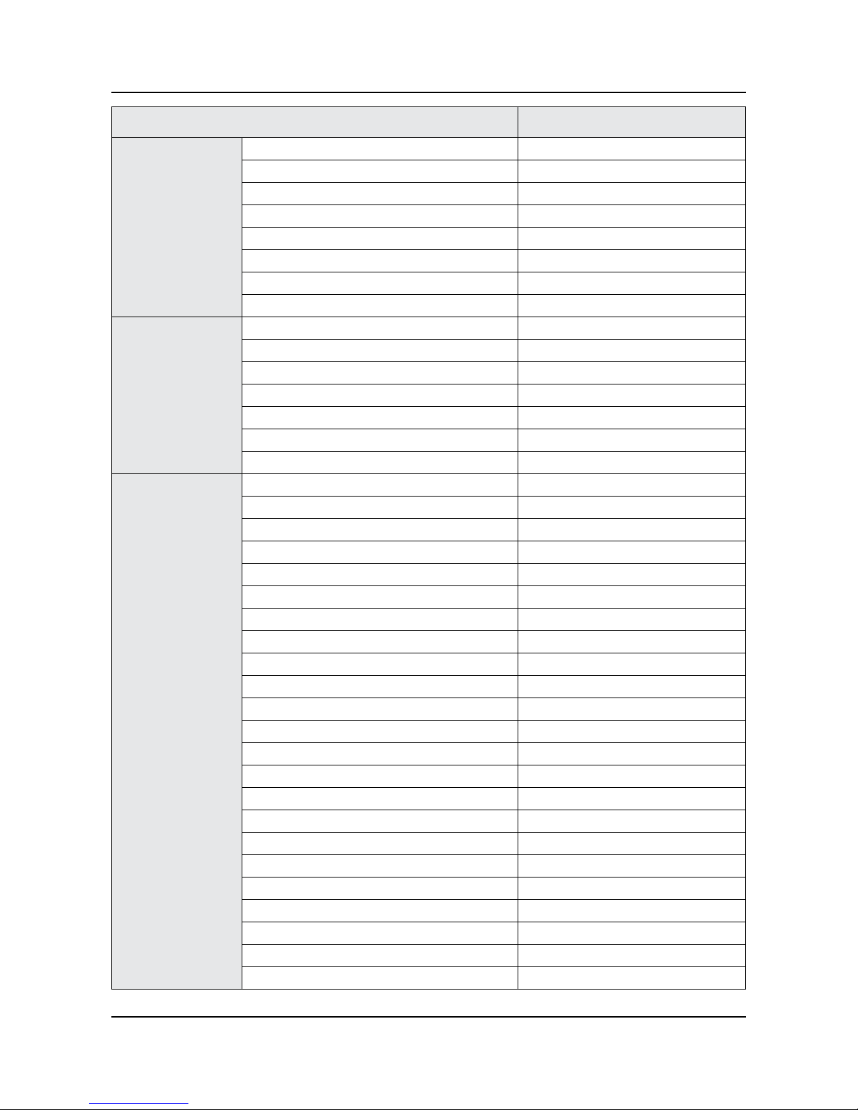
Item UN**JU7100FXZA
Connectivity
MHL Yes
Dongle Ready (3G / LTE) N/A
HDMI 3D Auto Setting Yes
HDMI A / Return Ch. Support Yes
HDMI Quick Switch Yes
Wireless LAN Adapter Support N/A
Wireless LAN Built-in 802.11ac
Anynet+ (HDMI-CEC) Yes
Design
Design Metallic Chamfer Flat
Bezel Type VNB
Slim Type Slim
Front Color Black
Light Effect (Deco) N/A
Stand Type Slim T-Stand
Swivel (Left/Right) N/A
Additional Feature
Samsung 3D Yes
3D Converter Yes
Instant On Yes
Camera Built-in N/A
Wireless Copy N/A
Processor Quad-Core
PX Ready N/A
21:9 Immersive Picture Mode N/A
SCSA Support Yes
Accessibility Voice Guide/Enlarge/High Contrast
Digital Clean View Yes
One Connect (Jack) Yes
Auto Channel Search Yes
Auto Power Off Yes
BD Wise Plus Yes
Caption (Subtitle) Yes
Channel List USB-Clone N/A
Connect Share™ (HDD) Yes
Connect Share™ Transfer N/A
ConnectShare™ (USB 2.0) Yes
AC/DC TV N/A
Sports Mode Basic
Story Replay N/A
2-7
2. Product specications
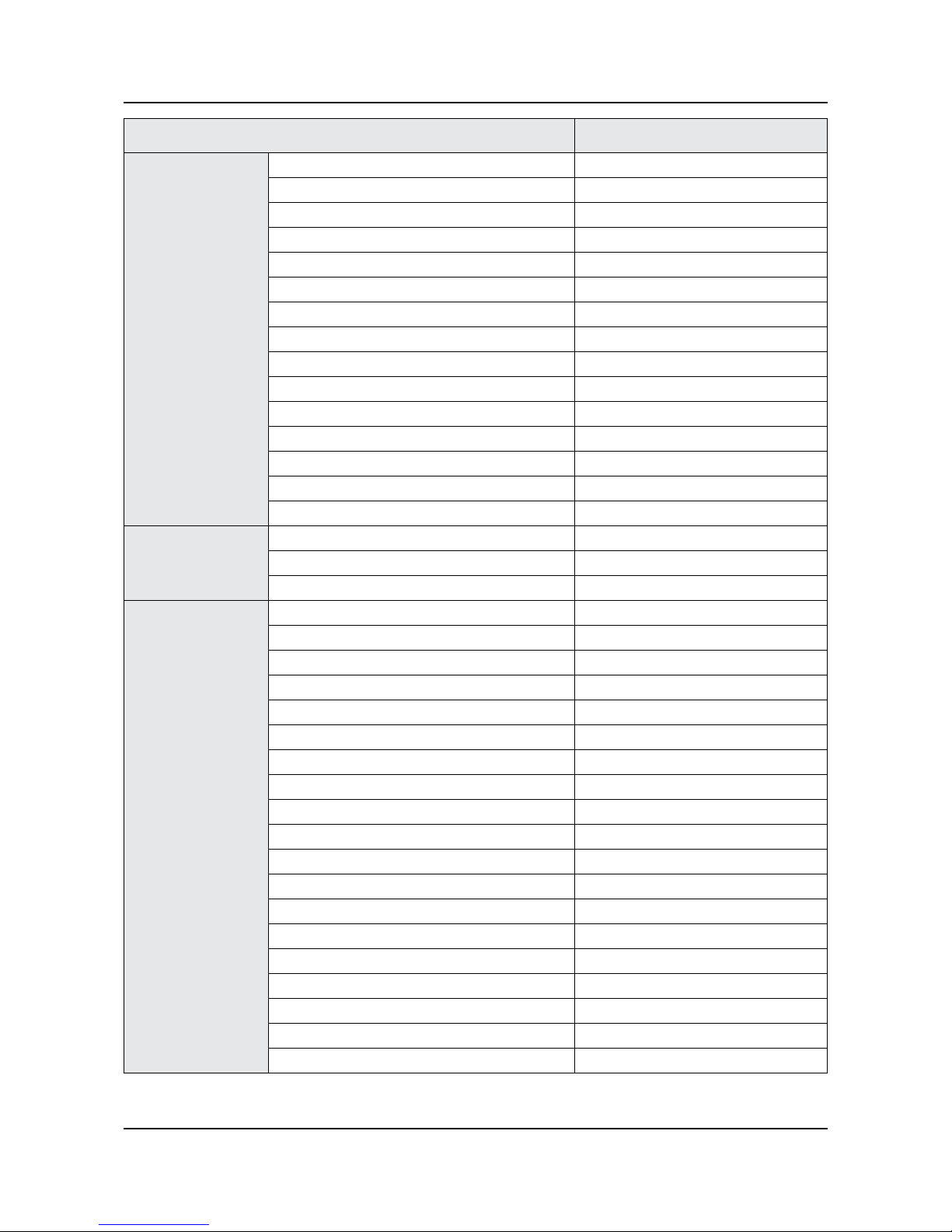
Item UN**JU7100FXZA
Additional Feature
Embeded POP Yes
EPG Yes
Extended PVR N/A
Game Mode Yes
IP Video Closed Caption Yes
OSD Language English, Spanish, French
Picture-In-Picture Yes
BT HID Built-in Yes
USB HID Support Yes
Smart Evolution Support N/A
Teletext (TTXT) N/A
Time Shift N/A
Analog Clean View N/A
Ultra Clean View Yes
Triple Protector N/A
Eco Feature
Eco Mark Energy Star 6.1
Eco Sensor Yes
Lead Presence Yes
Accessory
3D Active Glasses (Included) N/A
Remote Controller Model TM1560A
Batteries (for Remote Control) Yes
Samsung Smart Touch Control (Included) Yes
PX (Included) N/A
Ultra Slim Wall Mount Supported N/A
Mini Wall Mount Supported Yes
Vesa Wall Mount Supported Yes
Floor Stand Support Yes
TV Camera (Included) N/A
IR Extender Cable (Included) N/A
Wireless Keyboard (Included) N/A
Wireless PC Mirroring Adaptor (Included) N/A
Composite to Scart Gender (Included) N/A
User Manual Yes
E-Manual Yes
ANT-Cable N/A
Power Cable Yes
Slim Gender Cable 2
2-8
2. Product specications
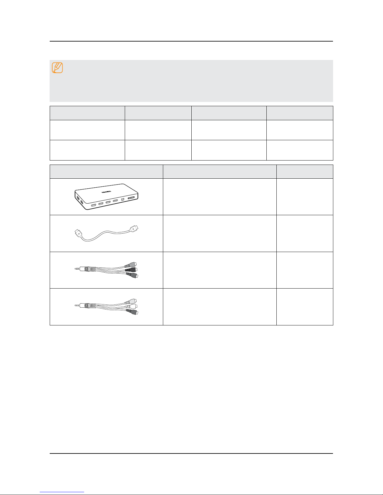
2-3. Accessories
NOTE
The items’ colors and shapes may vary depending on the model.•
Cables not included in the package contents can be purchased separately.•
The part code for some accessories may differ depending on your region.•
Product Code. No Product Code. No
Smart Touch Control• BN59-01220J Power Cord•
3903-000985 /
3903-000467 (75")
Batteries (AA x 2)• 4301-000101 User Manual•
BN68-06967A /
BN68-06967G (50"/60")
Image Product Code. No
One Connect Mini•
BN96-35817G /
BN96-35817H (75")
One Connect Mini Cable•
BN39-02015A /
BN39-02014A (75")
Component adapter• BN39-01154C
AV adapter• BN39-01154H
2-9
2. Product specications
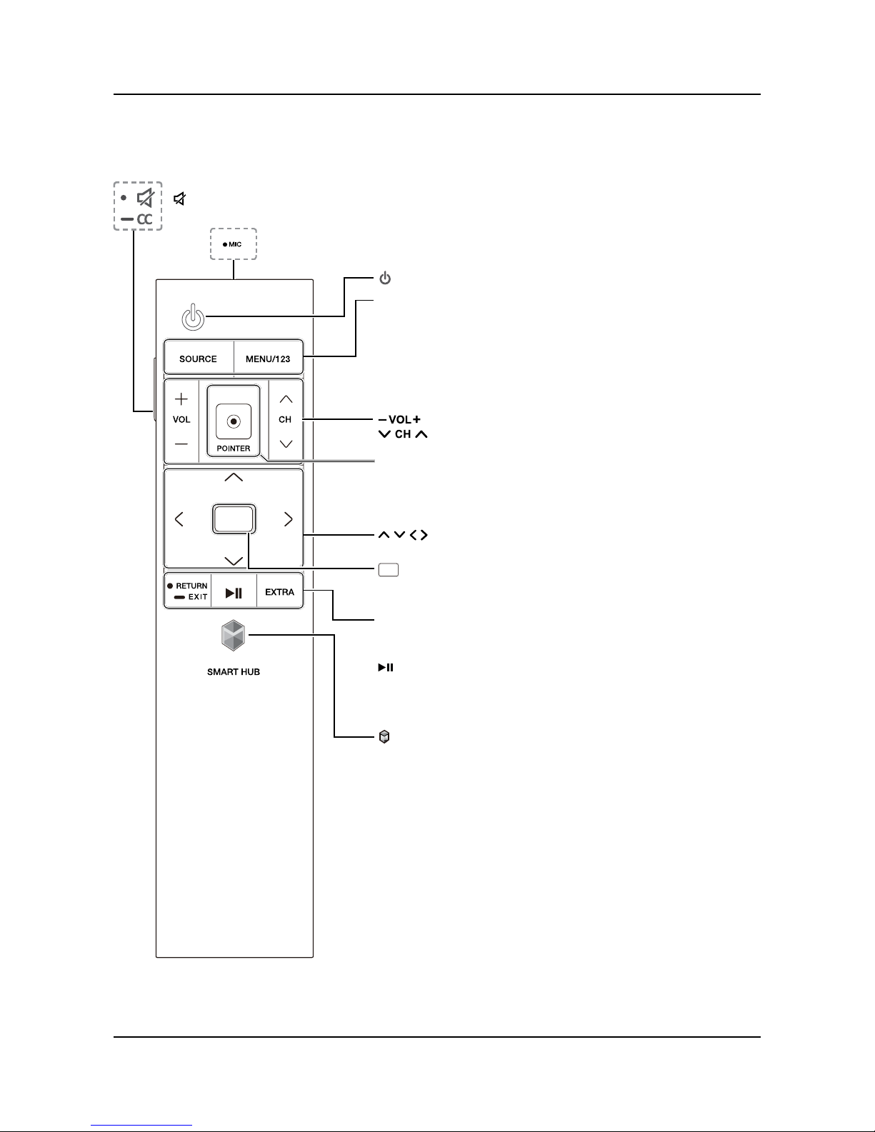
2-4. Viewing the Functions
The Samsung Smart Control
: Press this button to mute the sound temporarily.
CC: Press and hold this button to show or hide captions on the TV's screen.
MIC: Use the microphone with the Voice Recognition and Voice functions.
SOURCE: Displays and selects the available video sources.
MENU/123: Press this button to display the On-Screen Remote.
Displays the numeric buttons, the Source button, the Menu button,
and other function buttons on the top of the screen so that you can
run functions conveniently.
Press and hold this button to run the Voice Recognition function.•
POINTER: Place a nger on the POINTER button and move the
Samsung Smart Control. The pointer on the screen moves in the
direction you moved the Samsung Smart Control.
Press the POINTER button to select or run a focused item.
(Enter): Press this button to select or run a focused item.
Press and hold this button to launch the • Guide while you are
watching the TV.
RETURN: Press this button to return to the previous menu.
EXIT• : Press and hold this button to exit the currently running
function on the TV's screen.
: Use these buttons with a specic feature according to the
directions on the TV's screen.
EXTRA: Displays related information about the current program.
SMART HUB: Press this button to bring up Smart Hub
applications. (See the e-Manual chapter, "Smart Features >
Smart Hub.")
: Turns the TV on or off.
: Changes the volume.
: Changes the channel.
G G G
: Moves the focus and changes the values seen on the
TV's menu.
2-10
2. Product specications
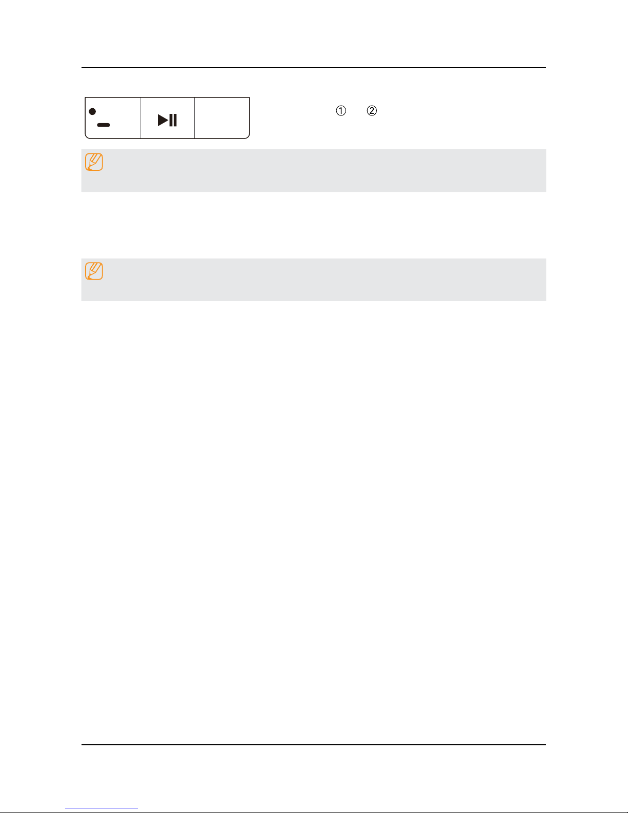
Pairing the TV to the Samsung Smart Control
ྙ ྚ
If your Samsung Smart Control is not paired to your TV, press and hold
the buttons labeled and simultaneously for 3 seconds or more to
pair the Samsung Smart Control to the TV.
NOTE
The Samsung Smart Control can only be paired to one TV at a time.
Using the SOURCE button to switch between video sources
Press the SOURCE button to switch between external devices connected to the TV. For example, to switch to a game
console connected to the second HDMI connector, press the SOURCE button. The Source list appears across the top of
the screen. From the Source list, select HDMI2.
NOTE
The connector names may differ with the product chosen.
2-11
2. Product specications
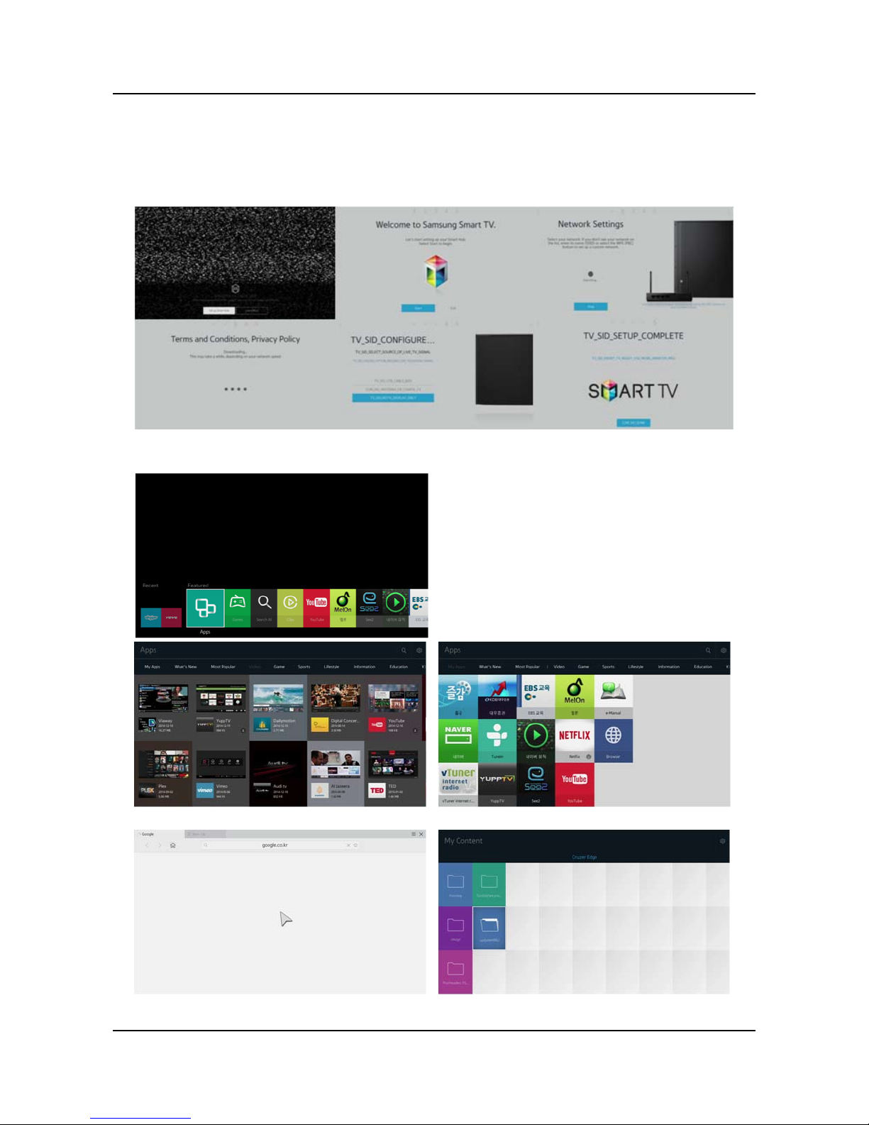
2-5. NEW Key Features
2-5-1. 15" New UI
SMART HUB START
After Smart HUB setup
<Videos contents> <My Apps>
<Web browser> <My contents>
2-12
2. Product specications
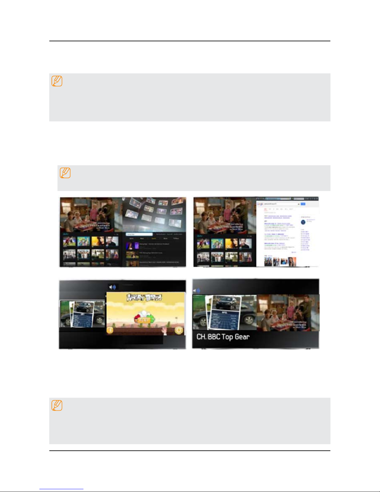
2-5-2. Multi Screen
Using Multi-Link Screen
NOTE
UHD and FHD contents and channels cannot be viewed simultaneously.•
Launching Smart Hub while using Multi-Link Screen automatically terminates Multi-Link Screen.•
Certain TV features and apps may not be supported by Multi-Link Screen. If this is the case, exit from Multi-Link •
Screen and than use the feature.
Selecting a Feature
Press the Samsung Smart Control's M.SCREEN button while Multi-Link Screen is running. 1.
The Options menu appears.
Select a feature from the Options menu. This initializes the selected feature.2.
NOTE
Features supported by Multi-Link Screen very depending on the country.
<TV + Video clip> <TV + Web search>
<TV + App> <TV +TV (dual tuner only)>
Using Multiple Functions in a Single Screen(Multi-Link Screen)
Menu > Picture > Open Multi-Link Screen
This function may not be available depending on the country or region.
This allows you to search the Web, use apps, and much more simultaneously while watching TV.
NOTE
Before using Multi-Link Screen, make sure the TV is connected to the lnternet. Using Multi-Link Screen requires •
an lnternet connection.
Before using Smart Hub with Multi-Link Screen, go to the On TV Settings (• Smart Hub > On TV Settings > On TV
Setup) and nish conguring Smart Hub.
2-13
2. Product specications
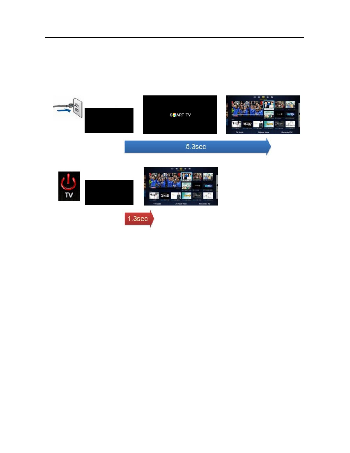
2-5-3. Instant On
Enabling the TV to Boot Faster
MENU > System > General > Samsung Instant On
Set Fast Boot on to have the TV boot up faster.
<Cold Boot>
Detachable power
<Instant On>
Remocon on

2-14
2. Product specications
2-6. HDMI 60P Mode
HDMI UHD 60P MODE
If an external UHD player is connected to the TV, follow these steps to convert the TV's HDMI connector optimized to the
UHD signals.
NOTE
Each HDMI connector can be individually optimized for HDMI UHD 60P MODE.
Turn off the external UHD player that is connected to the TV.1.
Navigate to 2. Picture > Picture Options > HDMI UHD 60P MODE, and set the UHD-connected HDMI connector to On.
When done, turn on the external UHD player.3.
NOTE
After setting the HDMI connector to • On, It takes some time to complete the conversion.
HDMI UHD 60P MODE• is specic to a UHD source, and does not operate properly for any other source. If you
want to play a non-UHD source in HDMI UHD 60P MODE, set the converted HDMI connector to Off.
2-15
2. Product specications
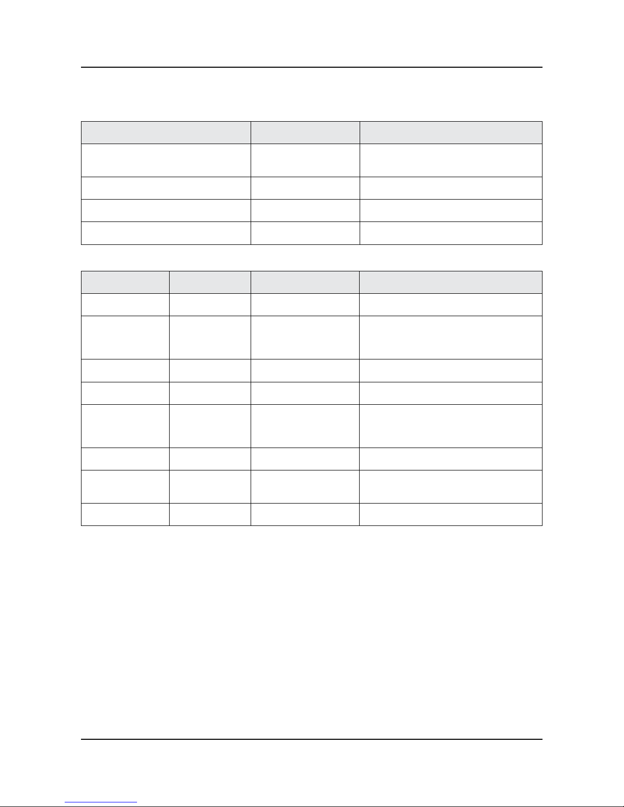
2-7. Supported Formats
Supported Image resolution
File Extension Type Resolution
*.jpg
*.jpeg
JPEG 15360x8640
*.png PNG 4096x4096
*.bmp BMP 4096x4096
*.mpo MPO 15360x8640
Supported Music File Formats
File Extension Type Codec Comments
*.mp3 MPEG MPEG1 Audio Layer 3 -
*.m4a
*.mpa
*.aac
MPEG4 AAC -
*.ac FLAC FLAC Supports up to two channels.
*.ogg OGG Vorbis Supports up to two channels.
*.wma WMA WMA
WMA 10 Pro supports up to 5.1 channels.
WMA lossless audio is not supported.
Supports up to M2 prole.
*.wav wav wav -
*.mid
*.midi
midi midi Type 0, type 1 and supported.
*.ape ape ape -
Sound or video may not work if they have standard bit rates/frame rates above the TV’s compatibility.•
If the Index Table is wrong, the Seek (Jump) function does not work.•
When playing video over a network connection, the video may not play smoothly because of data•
Some USB/digital camera devices may not be compatible with the player.•
2-16
2. Product specications
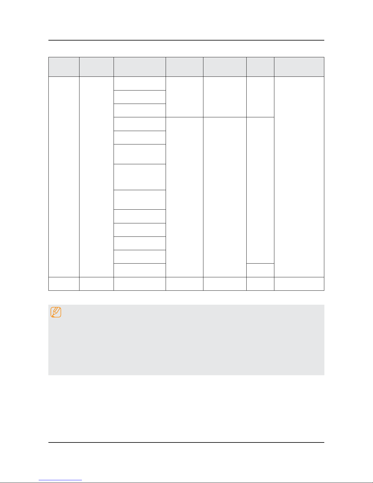
Supported Video Code
File
Formats
Container Video Codecs Resolution
Frame rate
(fps)
Bit rate
(Mbps)
Audio Codec
*.avi
*.mkv
*.asf
*.wmv
*.mp4
*.mov
*.3gp
*.vro
*.mpg
*.mpeg
*.ts
*.tp
*.trp
*.mov
*.v
*.vob
*.svi
*.m2ts
*.mts
*.divx
AVI
MKV
ASF
MP4
3GP
MOV
FLV
VRO
VOB
PS
TS
SVAF
H.264 BP/MP/HP
4096x2160
UHD: MAX 30
FHD: MAX 30
HD : MAX 60
UHD: 60
60
AC3
LPCM
ADPCM
(IMA, MS)
AAC
HE-AAC
WMA
Dolby Digital
Plus
MPEG(MP3)
DTS
(Core, LBR)
G.711(A-Law,
μ-Law
Motion JPEG
HEVC(H.265)
DivX 3.11/4/5/6
1920x1080
FHD: 30
HD : 60
30
MPEG4 SP/ASP
Microsoft MPEG-
4 v1 , v2 , v3
Window Media
Video v7(WMV1),
v8(WMV2)
Window Media
Video v9(VC1)
MPEG2
MPEG1
VP6
H.263 Sorrenson
MVC 60
*.webm WebM VP8 1920x1080 6~30 20 Vorbis
Other Restrictions
NOTE
Codecs may not function properly if there is a problem with the content data.•
Video content does not play or does not correctly if there is an error in the content or container.•
Sound or video may not work if they have standard bit rates/frame rates above the TV's compatibility.ratings•
If the Index Table is wrong, the Seek(Jump) function does not work.•
When playing video over a network connection, the video may not play smoothly because of datatransmission •
speeds.
Some USB/digital camera devices may not be compatible with the player.•
3-1
3. Disassembly and Reassemble
3. Disassembly and Reassembly
This section of the service manual describes the disassembly and reassembly procedures for the LED TV.
WARNING
This LED TV contains electrostatically sensitive devices. Use caution when handling these components.
3-1. Disassembly and Reassembly
CAUTION
Disconnect the LED TV from the power source before disassembly.1.
Follow these directions carefully; never use metal instruments to pry apart the cabinet.2.
If there is no additional coment, it is same for all inches.3.
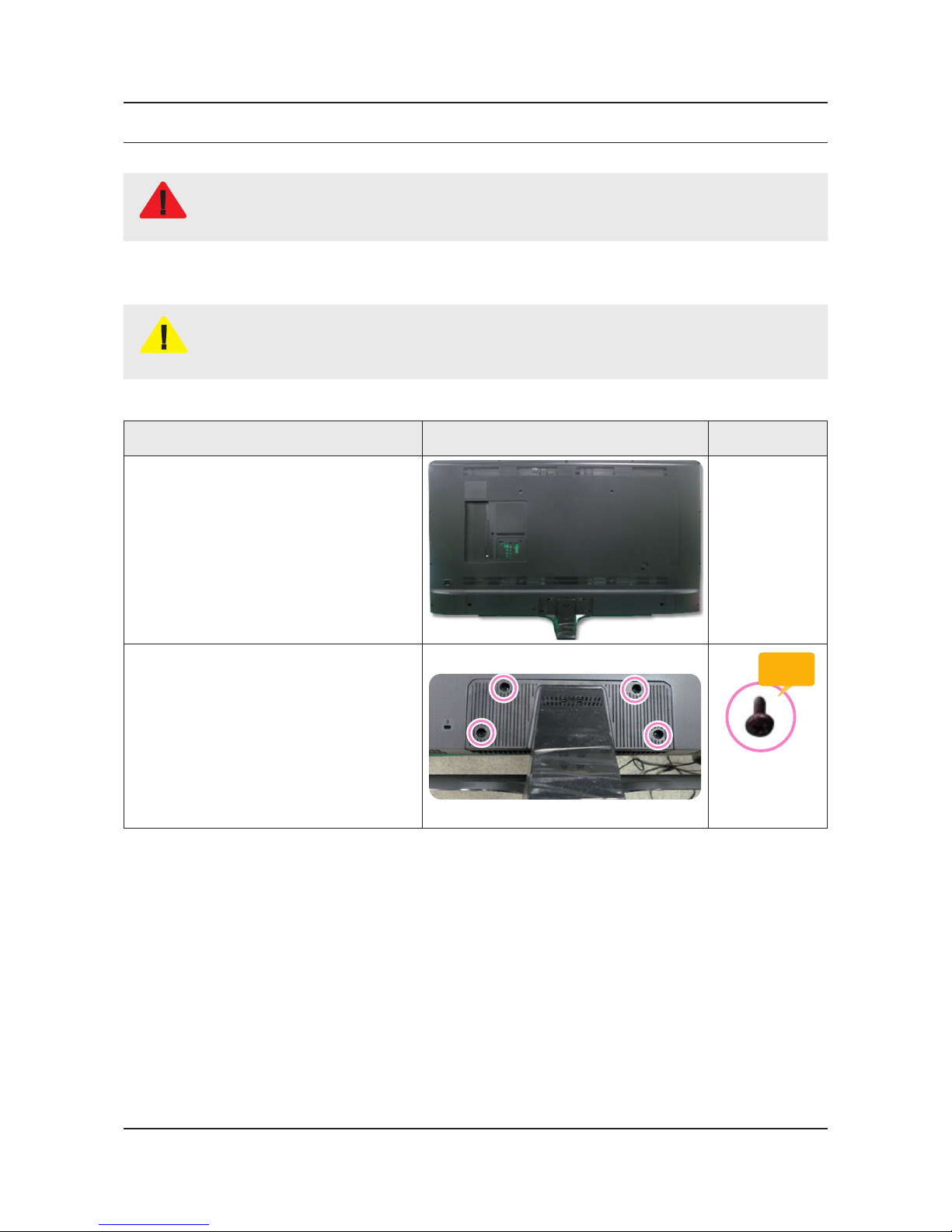
3-1-1. TV Disassembly
Description Picture Description Screws
1
Place TV face down on cushioned table.
2
Remove 4 screws from the ASSY
STAND P-BAS.
Torque :
7~ 8Kgf.cm.
BN61-09494D
(40"/50"/55")
6003-001334
(60"/65"/75")
 Loading...