

Page 1
LED TV
Chassis : UNV72
Model : UN32M5300AF
UN40M5300AF
UN43M5300AF
UN49M5300AF
UN50M5300AF
SERVICE
LED TV Contents
1. Precautions
2. Product specications
3. Disassembly and Reassembly
4. Troubleshooting
5. Wiring Diagram
Manual
UN**M5300AF
Page 2

Contents
1. Precautions .............................................................................................................. 1-1
1-1. Safety Precautions ......................................................................................................... 1-1
1-1-1. Warnings .............................................................................................................. 1-1
1-1-2. Servicing the LED TV ........................................................................................... 1-1
1-1-3. Fire and Shock Hazard ........................................................................................ 1-1
1-1-4. Product Safety Notices ........................................................................................ 1-2
1-2. Servicing Precautions ..................................................................................................... 1-3
1-2-1. General Servicing Precautions ............................................................................ 1-3
1-3. Static Electricity Precautions .......................................................................................... 1-4
1-4. Installation Precautions .................................................................................................. 1-5
2. Product Specications............................................................................................ 2-1
2-1. Product information ........................................................................................................ 2-1
2-2. Product specication ...................................................................................................... 2-3
2-2-1. Detailed Specications ......................................................................................... 2-3
2-2-2. Specications ..................................................................................................... 2-29
2-3. Accessories ................................................................................................................. 2-30
3. Disassembly and Reassembly ............................................................................... 3-1
3-1. Disassembly and Reassembly ....................................................................................... 3-1
4. Troubleshooting ...................................................................................................... 4-1
4-1. Troubleshooting .............................................................................................................. 4-1
4-2. How to Check Fault Symptom ........................................................................................ 4-2
4-2-1. Power ................................................................................................................... 4-2
4-2-2. Main ..................................................................................................................... 4-5
4-2-3. Video .................................................................................................................... 4-9
4-2-4. Audio .................................................................................................................. 4-11
4-2-5. Network .............................................................................................................. 4-12
4-2-6. WiFi Module ....................................................................................................... 4-13
4-2-7. FUNCTION/IR Control ....................................................................................... 4-14
4-3. Factory Mode Adjustments ........................................................................................... 4-15
4-3-1. Detail Factory Option ......................................................................................... 4-15
4-3-2. Entering Factory Mode ....................................................................................... 4-20
4-4. White Balance .............................................................................................................. 4-27
4-4-1. Calibration .......................................................................................................... 4-27
4-4-2. Service Adjustment ............................................................................................ 4-27
4-5. Software Upgrade ......................................................................................................... 4-29
4-5-1. By USB .............................................................................................................. 4-29
4-5-2. By Online ........................................................................................................... 4-29
4-5-3. Alternative Software (Backup) ............................................................................ 4-29
5. Wiring Diagram ........................................................................................................ 5-1
5-1. Wiring Diagram ............................................................................................................... 5-1
5-2. Connector ....................................................................................................................... 5-3
Page 3

ANNEX. Exploded View & Part List [UN32M5300AFXZA XA01] ....................ANNEX-1
1-1. Exploded View ......................................................................................................ANNEX-1
1-1-1. Parts List ....................................................................................................ANNEX-1
2-1. Electrical Parts List ...............................................................................................ANNEX-2
ANNEX. Exploded View & Part List [UN40M5300AFXZA DA01] ....................ANNEX-1
1-1. Exploded View ......................................................................................................ANNEX-1
1-1-1. Parts List ....................................................................................................ANNEX-1
2-1. Electrical Parts List ...............................................................................................ANNEX-2
ANNEX. Exploded View & Part List [UN43M5300AFXZA BA01] ....................ANNEX-1
1-1. Exploded View ......................................................................................................ANNEX-1
1-1-1. Parts List ....................................................................................................ANNEX-1
2-1. Electrical Parts List ...............................................................................................ANNEX-2
ANNEX. Exploded View & Part List [UN49M5300AFXZA FA01].....................ANNEX-1
1-1. Exploded View ......................................................................................................ANNEX-1
1-1-1. Parts List ....................................................................................................ANNEX-1
2-1. Electrical Parts List ...............................................................................................ANNEX-2
ANNEX. Exploded View & Part List [UN50M5300AFXZA DA01] ....................ANNEX-1
1-1. Exploded View ......................................................................................................ANNEX-1
1-1-1. Parts List ....................................................................................................ANNEX-1
2-1. Electrical Parts List ...............................................................................................ANNEX-2
Page 4

This Service Manual is a property of Samsung Electronics Co.,Ltd.
Any unauthorized use of Manual can be punished under applicable
International and/or domestic law.
© 2017 Samsung Electronics Co.,Ltd.
All rights reserved.
Printed in Korea
Page 5
1. Precautions
1. Precautions
1-1. Safety Precautions
Follow these safety, servicing and ESD precautions to prevent damage and to protect against potential hazards such as
electrical shock.
1-1-1. Warnings
For continued safety, do not attempt to modify the circuit board.
WARNING
1-1-2. Servicing the LED TV
When servicing the LED TV, Disconnect the AC line cord from the AC outlet.1.
It is essential that service technicians have an accurate voltage meter available at all times. Check the calibration of this 2.
meter periodically.
1-1-3. Fire and Shock Hazard
Before returning the monitor to the user, perform the following safety checks:
Inspect each lead dress to make certain that the leads are not pinched or that hardware is not lodged between the 1.
chassis and other metal parts in the monitor.
Inspect all protective devices such as nonmetallic control knobs, insulating materials, cabinet backs, adjustment and 2.
compartment covers or shields, isolation resistorcapacitor networks, mechanical insulators, etc.
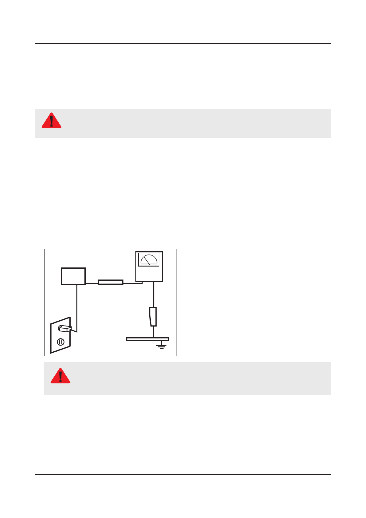
Leakage Current Hot Check:3.
Disconnect the AC power and DC power jack before servicing.
(READING SHOULD)
DEVICE
UNDER
TEST
ALSO TEST WITH
PLUG REVERSED
(USING AC ADAPTER
PLUG AS REQUIRED)
NOT BE ABOVE 0.5mA
2-WIRE CORD
TEST ALL
EXPOSED METAL
SURFACES
LEAKAGE
CURRENT
TESTER
EARTH
GROUND
Do not use an isolation transformer during this test.
Use a leakage current tester or a metering system that complies with American National Standards
WARNING
Institute (ANSI C101.1, Leakage Current for Appliances), and Underwriters Laboratories (UL
Publication UL1410, 59.7).
With the unit completely reassembled, plug the AC line cord directly into a 120V AC outlet. With the unit’s AC switch rst 4.
in the ON position and then OFF, measure the current between a known earth ground (metal water pipe, conduit, etc.)
and all exposed metal parts, including: metal cabinets, screwheads and control shafts.
The current measured should not exceed 0.5 milliamp.
Reverse the power-plug prongs in the AC outlet and repeat the test.
1-1
Page 6

1-2
1. Precautions
1-1-4. Product Safety Notices
Some electrical and mechanical parts have special safetyrelated characteristics which are often not evident from visual
inspection. The protection they give may not be obtained by replacing them with components rated for higher voltage,
wattage, etc. Parts that have special safety characteristics are identied by on schematics and parts lists. A substitute
replacement that does not have the same safety characteristics as the recommended replacement part might create
shock, re and/or other hazards. Product safety is under review continuously and new instructions are issued whenever
appropriate.
Page 7

1-3
1. Precautions
1-2. Servicing Precautions
An electrolytic capacitor installed with the wrong polarity might explode.
WARNING
Before servicing units covered by this service manual, read and follow the Safety Precautions section of
CAUTION
NOTE
1-2-1. General Servicing Precautions
Always unplug the unit’s AC power cord from the AC power source and disconnect the DC Power Jack before 1.
attempting to: (a) remove or reinstall any component or assembly, (b) disconnect PCB plugs or connectors, (c) connect
a test component in parallel with an electrolytic capacitor.
Some components are raised above the printed circuit board for safety. An insulation tube or tape is sometimes used. 2.
The internal wiring is sometimes clamped to prevent contact with thermally hot components. Reinstall all such elements
to their original position.
After servicing, always check that the screws, components and wiring have been correctly reinstalled. Make sure that 3.
the area around the serviced part has not been damaged.
Check the insulation between the blades of the AC plug and accessible conductive parts (examples: metal panels, input 4.
terminals and earphone jacks).
Insulation Checking Procedure: Disconnect the power cord from the AC source and turn the power switch ON. Connect 5.
an insulation resistance meter (500 V) to theblades of the AC plug. The insulation resistance between each blade of the
AC plug and accessible conductive parts (see above) should be greater than 1 megohm.
Always connect a test instrument’s ground lead to the instrument chassis ground before connecting the positive lead; 6.
always remove the instrument’s ground lead last.
this manual.
If unforeseen circumstances create conict between the following servicing precautions and any of the
safety precautions, always follow the safety precautions.
Page 8

1-4
1. Precautions
1-3. Static Electricity Precautions
Some semiconductor (solid state) devices can be easily damaged by static electricity. Such components are commonly
called Electrostatically Sensitive Devices (ESD). Examples of typical ESD are integrated circuits and some eld-effect
transistors. The following techniques will reduce the incidence of component damage caused by static electricity.
Immediately before handling any semiconductor components or assemblies, drain the electrostatic charge from your 1.
body by touching a known earth ground. Alternatively, wear a discharging wrist-strap device. To avoid a shock hazard,
be sure to remove the wrist strap before applying power to the monitor.
After removing an ESD-equipped assembly, place it on a conductive surface such as aluminum foil to prevent 2.
accumulation of an electrostatic charge.
Do not use freon-propelled chemicals. These can generate electrical charges sufcient to damage ESDs.3.
Use only a grounded-tip soldering iron to solder or desolder ESDs.4.
Use only an anti-static solder removal device. Some solder removal devices not classied as “anti-static” can generate 5.
electrical charges sufcient to damage ESDs.
Do not remove a replacement ESD from its protective package until you are ready to install it. Most replacement ESDs 6.
are packaged with leads that are electrically shorted together by conductive foam, aluminum foil or other conductive
materials.
Immediately before removing the protective material from the leads of a replacement ESD, touch the protective material 7.
to the chassis or circuit assembly into which the device will be installed.
Be sure no power is applied to the chassis or circuit and observe all other safety precautions.
CAUTION
Minimize body motions when handling unpackaged replacement ESDs. Motions such as brushing clothes together, or 8.
lifting your foot from a carpeted oor can generate enough static electricity to damage an ESD.
Page 9

1-5
1. Precautions
1-4. Installation Precautions
For safety reasons, more than a people are required for carrying the product.1.
Keep the power cord away from any heat emitting devices, as a melted covering may cause re or electric shock.2.
Do not place the product in areas with poor ventilation such as a bookshelf or closet. The increased internal temperature 3.
may cause re.
Bend the external antenna cable when connecting it to the product. This is a measure to protect it from being exposed 4.
to moisture. Otherwise, it may cause a re or electric shock.
Make sure to turn the power off and unplug the power cord from the outlet before repositioning the product. Also check 5.
the antenna cable or the external connectors if they are fully unplugged. Damage to the cord may cause re or electric
shock.
Keep the antenna far away from any high-voltage cables and install it rmly. Contact with the highvoltage cable or the 6.
antenna falling over may cause re or electric shock.
When installing the product, leave enough space (0.4m) between the product and the wall for ventilation purposes. 7.
A rise in temperature within the product may cause re.
If an equipment is provided with a replaceable battery, and if replacement by an incorrect type could result in an 8.
explosion (for example, with some lithium batteries), the following applies:
Risk of explosion if battery is replaced by an incorrect type dispose of used batteries according to •
the instructions.
Do not dispose of batteries in a re.•
Do not short circuit, disassemble or overheat the batteries.•
CAUTION
Danger of explosion if battery is incorrectly replaced. Replace only with the same or equivalent •
type.
Do not be exposed to excessive heat such as sunshine, re or the like.•
Page 10
2. Product Specications
2-1. Product information
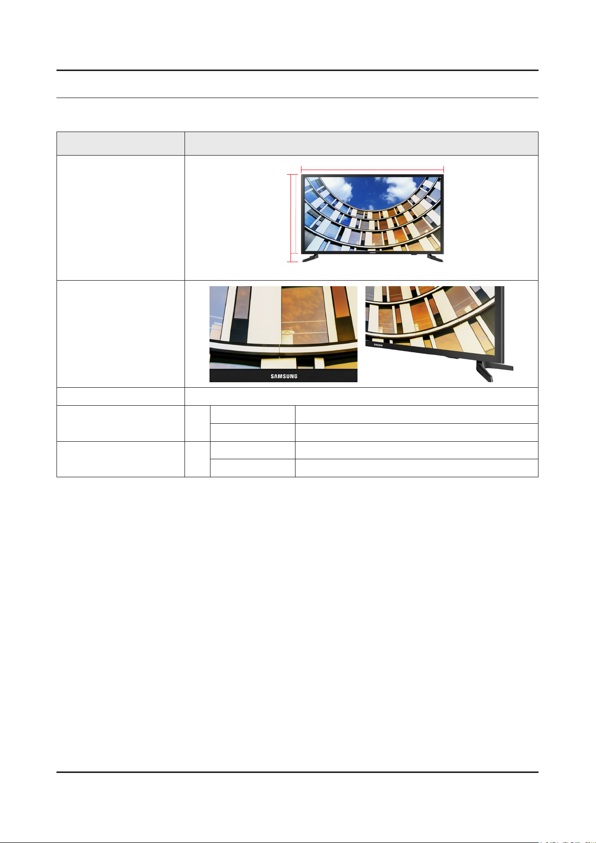
Model UN32M5300AF
2. Product specications
W
Front View
Detail View
Color Front : GLOSSY BLACK, Stand : BLACK(HAIR LINE)
Dimensions
(W x H x D)
Weight
32"
32"
With Stand 741.0 x 468.7 x 145.4 mm
Without Stand 741.0 x 436.2 x 69.0 mm
With Stand 3.9 kg
Without Stand 3.8 kg
H
* W : Width H : High
2-1
Page 11
2-2
2. Product specications
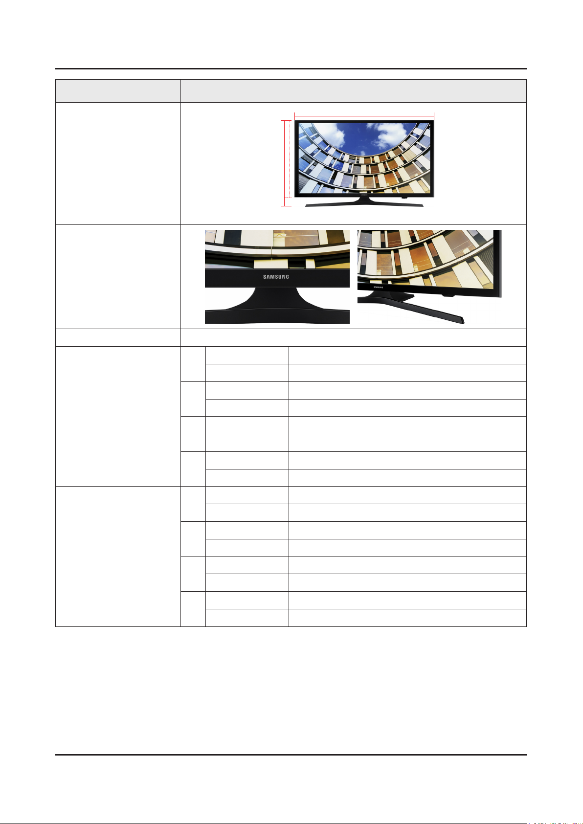
Model UN**M5300AF
W
Front View
H
* W : Width H : High
Detail View
Color Front : GLOSSY BLACK, Stand : BLACK(HAIR LINE)
With Stand 922.7 x 594.9 x 337.5 mm
40"
Without Stand 922.7 x 531.0 x 72.6 mm
With Stand 985.5 x 637.4 x 337.5 mm
43"
Dimensions
(W x H x D)
Without Stand 985.5 x 574.8 x 73.4 mm
With Stand 1118.8 x 714.1 x 337.5 mm
49"
Without Stand 1118.8 x 650.0 x 74.2 mm
Weight
50"
With Stand 1140.8 x 726.0 x 337.5 mm
Without Stand 1140.8 x 662.3 x 72.9 mm
With Stand 8.6 kg
40"
Without Stand 7.0 kg
With Stand 9.4 kg
43"
Without Stand 7.8 kg
With Stand 11.9 kg
49"
Without Stand 10.3 kg
With Stand 12.6 kg
50"
Without Stand 11.1 kg
Page 12
2-3
2. Product specications
2-2. Product specication
2-2-1. Detailed Specications
NOTE
Design and specications are subject to change without prior notice.
Item UN32M5300AFXZA
General Information
Display
Video
Product LED
Cabinet Basic Code U32MJ2
Series 5
Country UNITED STATES
Tools Support N/A
Platform(TV) SoC | KANT-S
Inch 32
Real Inch 31.5
Q Display N/A
Resolution 1920 x 1080
Screen Curvature N/A
10bit Support N/A
Bendable Panel N/A
Ultra Black N/A
Picture Engine HyperReal
Motion Rate 60
PQI (Picture Quality Index) 500
HDR (High Dynamic Range) N/A
Q Contrast Ultimate N/A
Q Contrast N/A
Dynamic Contrast Ratio Mega Contrast
Micro Dimming M/D Pro
Precision Black (Local Dimming) N/A
Q Color N/A
Dynamic Crystal Color N/A
Active Crystal Color N/A
Wide Color Enhancer (Plus) Yes
PurColor Yes
Q Everyview N/A
Auto Depth Enhancer N/A
Contrast Enhancer Yes
Page 13
2-4
2. Product specications
Item UN32M5300AFXZA
Video
Audio
Auto Motion Plus Yes
Film Mode Yes
Picture WSS,HDMI Black Level
Response Time 8ms
Viewing Angle (H/V) 178/178
Natural Mode Support Yes
Peak Illuminator N/A
Quantum Dot Color N/A
Dolby Digital Plus Yes
DTS Codec Yes
Sound Output (RMS) 10W(5W+5W)
Speaker Type 2CH(Down Firing + Base Reex)
Woofer N/A
Main Speaker Output (W) 20W(10W+10W)
Woofer Speaker Output (W) N/A
Twitter Speaker Output (W) N/A
Smart Service
VESA Standard
Smart Feature
Multiroom Link N/A
Bluetooth Audio N/A
Smart TV Type Smart
Voice Interaction N/A
TV Plus N/A
Web Browser Yes
One app Support N/A
Smart View N/A
Screw Size M4
Screw depth 20.9~21.9
VESA Spec 100.0 x 100.0
TV to Mobile - Mirroring Yes
Mobile to TV - Mirroring, DLNA Yes
360 Video Player N/A
360 Camera Support N/A
Family Square with S-Cloud N/A
Together play Yes
Easy Setup N/A
App Casting Yes
Wireless TV On - Samsung WOL Yes
Page 14

2-5
2. Product specications
Item UN32M5300AFXZA
Smart Feature
Localization
Wired TV On - Samsung WOL Yes
Bluetooth Low Energy N/A
RVU N/A
WiFi Direct Yes
CVP-2 N/A
TV as Hub Support N/A
TV as Things Support N/A
IoT Client Application N/A
S-Share N/A
Dongle Compatibility (3G / LTE / WiFi)
Wireless Copy N/A
Sound Mirroring N/A
Analog Clean View N/A
Cricket Prediction N/A
Sports Mode N/A
Senior mode N/A
N/A
Feature
Clean View N/A
Family TV 2.0 N/A
Local Cinema Mode N/A
All Care Protection N/A
Décor Mode Picture Engine N/A
Décor Mode N/A
Low Power (Décor Mode) N/A
Bluetooth Speaker (Frame) N/A
Motion Detection (Frame) N/A
Intelligent Picture and Sound Dynamic Media
Intelligent Picture and Sound- IP
Streaming
Instant On Yes
Processor Quad-core
SCSA Support N/A
Accessibility
Digital Clean View Yes
Voice Guide(US English)/ Enlarge/ High Contrast/
Learn TV Remote(US English)/ Multi-output Audio
N/A
N/A
Ultra Clean View Yes
Auto Channel Search Yes
Auto Power Off Yes
Page 15
2-6
2. Product specications
Item UN32M5300AFXZA
Feature
Caption (Subtitle) Yes
ConnectShare™ (HDD) Yes
ConnectShare™ (USB 2.0) Yes
ConnectShare™ Transfer N/A
Embeded POP Yes
EPG Yes
Extended PVR N/A
Game Mode Yes
ENG,EST,FIN,FRA,DEU,GRE,HUN,ITA,LAT,LTU,
OSD Language
Picture-In-Picture N/A
BT HID Support N/A
USB HID Support Yes
Teletext (TTX) N/A
Time Shift N/A
One Connect N/A
NOR,POL,POR,ROM,SER,SLK,SPA,SWE,BUL,C
RO,CZE,DAN,DUT,SLV,ALB,MKD,BOS,KOR
Additional Feature
System
Core Component
V-Chip Yes
MBR Support N/A
IPv6 Support Yes(US)
Gigabit N/A
- -
Digital Broadcasting ATSC / Clear QAM
DTV Sound System Dolby
Analog Tuner Yes
Analog Tuner Type NTSC 3.58
2 Tuner N/A
CI (Common Interface) N/A
Data Broadcasting N/A
ATV Sound System M
Tuner Vendor & Model (SoluM) | DTVS20EH7A
TV Key N/A
DDR SDRAM Hynix
Flash Memory EMMC | Toshiba
Serial Flash Memory WINBOND
HDMI Switch N/A
Display Device Vender BOE
Page 16
2-7
2. Product specications
Item UN32M5300AFXZA
Connectivity
HDMI 2
Resolution 1920 x 1080i 60
DVI Support Port N/A
MHL Support Port N/A
USB 1
Port 1 Type 2.0
Port 2 Type N/A
Port 3 Type N/A
Port 4 Type N/A
Port 5 Type N/A
Component In (Y/Pb/Pr) 1
Composite In (AV) 1(Common Use for Component Y)
Ethernet (LAN) 1
Audio Out (Mini Jack / LR) N/A
Digital Audio Out (Optical) 1
RF In (Terrestrial / Cable input /
Satellite Input)
Ex-Link ( RS-232C ) N/A
CI Slot N/A
Monitor Output N/A
1/1(Common Use for Terrestrial)/0
Design
Eco
DVI
Resolution N/A
D-Sub Resolution N/A | N/A
HDMI A / Return Ch. Support Yes
HDMI Quick Switch Yes
Wireless LAN Adapter Support N/A
Wireless LAN Built-in Yes
Anynet+ (HDMI-CEC) Yes
Design North America J5200 re-use
Bezel Type NNB
Slim Type 58mm
Front Color Black Hairline
Light Effect (Deco) N/A
Stand Type Y Feet (Metallic Silver-SMT)
Swivel (Left/Right) N/A
Energy Efciency Class Yes
Eco Mark N/A
Page 17
2-8
2. Product specications
Item UN32M5300AFXZA
Eco
Security
General Information
Display
Eco Sensor Yes
Mercury Content (mg) 0.0
Lead Presence Yes
- -
Item UN40M5300AFXZA
Product LED
Cabinet Basic Code U40MJ1
Series 5
Country UNITED STATES
Tools Support N/A
Platform(TV) SoC | KANT-S
Inch 40
Real Inch 39.5
Q Display N/A
Resolution 1920 x 1080
Screen Curvature N/A
Video
10bit Support N/A
Bendable Panel N/A
Ultra Black N/A
Picture Engine HyperReal
Motion Rate 60
PQI (Picture Quality Index) 500
HDR (High Dynamic Range) N/A
Q Contrast Ultimate N/A
Q Contrast N/A
Dynamic Contrast Ratio Mega Contrast
Micro Dimming M/D Pro
Precision Black (Local Dimming) N/A
Q Color N/A
Dynamic Crystal Color N/A
Active Crystal Color N/A
Wide Color Enhancer (Plus) Yes
PurColor Yes
Q Everyview N/A
Auto Depth Enhancer N/A
Contrast Enhancer Yes
Page 18

2-9
2. Product specications
Item UN40M5300AFXZA
Video
Audio
Auto Motion Plus Yes
Film Mode Yes
Picture WSS,HDMI Black Level
Response Time 8ms
Viewing Angle (H/V) 178/178
Natural Mode Support Yes
Peak Illuminator N/A
Quantum Dot Color N/A
Dolby Digital Plus Yes
DTS Codec Yes
Sound Output (RMS) 20W(10W+10W)
Speaker Type 2CH(Down Firing + Base Reex)
Woofer N/A
Main Speaker Output (W) 20W(10W+10W)
Woofer Speaker Output (W) N/A
Twitter Speaker Output (W) N/A
Smart Service
VESA Standard
Smart Feature
Multiroom Link N/A
Bluetooth Audio N/A
Smart TV Type Smart
Voice Interaction N/A
TV Plus N/A
Web Browser Yes
One app Support N/A
Smart View N/A
Screw Size M8
Screw depth 20~21
VESA Spec 200.0 x 200.0
TV to Mobile - Mirroring Yes
Mobile to TV - Mirroring, DLNA Yes
360 Video Player N/A
360 Camera Support N/A
Family Square with S-Cloud N/A
Together play Yes
Easy Setup N/A
App Casting Yes
Wireless TV On - Samsung WOL Yes
Page 19
2-10
2. Product specications
Item UN40M5300AFXZA
Smart Feature
Localization
Wired TV On - Samsung WOL Yes
Bluetooth Low Energy N/A
RVU N/A
WiFi Direct Yes
CVP-2 N/A
TV as Hub Support N/A
TV as Things Support N/A
IoT Client Application N/A
S-Share N/A
Dongle Compatibility (3G / LTE / WiFi)
Wireless Copy N/A
Sound Mirroring N/A
Analog Clean View N/A
Cricket Prediction N/A
Sports Mode N/A
Senior mode N/A
Clean View N/A
N/A
Feature
Family TV 2.0 N/A
Local Cinema Mode N/A
All Care Protection N/A
Décor Mode Picture Engine N/A
Décor Mode N/A
Low Power (Décor Mode) N/A
Bluetooth Speaker (Frame) N/A
Motion Detection (Frame) N/A
Intelligent Picture and Sound Dynamic Media
Intelligent Picture and Sound- IP
Streaming
Instant On Yes
Processor Quad-core
SCSA Support N/A
Accessibility
Digital Clean View Yes
Voice Guide(US English)/ Enlarge/ High Contrast/
Learn TV Remote(US English)/ Multi-output Audio
N/A
N/A
Ultra Clean View Yes
Auto Channel Search Yes
Auto Power Off Yes
Page 20

2-11
2. Product specications
Item UN40M5300AFXZA
Feature
Caption (Subtitle) Yes
ConnectShare™ (HDD) Yes
ConnectShare™ (USB 2.0) Yes
ConnectShare™ Transfer N/A
Embeded POP Yes
EPG Yes
Extended PVR N/A
Game Mode Yes
ENG,EST,FIN,FRA,DEU,GRE,HUN,ITA,LAT,LTU,
OSD Language
Picture-In-Picture N/A
BT HID Support N/A
USB HID Support Yes
Teletext (TTX) N/A
Time Shift N/A
One Connect N/A
NOR,POL,POR,ROM,SER,SLK,SPA,SWE,BUL,C
RO,CZE,DAN,DUT,SLV,ALB,MKD,BOS,KOR
Additional Feature
System
Core Component
V-Chip Yes
MBR Support N/A
IPv6 Support Yes(US)
Gigabit N/A
- -
Digital Broadcasting ATSC / Clear QAM
DTV Sound System Dolby
Analog Tuner Yes
Analog Tuner Type NTSC 3.58
2 Tuner N/A
CI (Common Interface) N/A
Data Broadcasting N/A
ATV Sound System M
Tuner Vendor & Model (SoluM) | DTVS20EH7A
TV Key N/A
DDR SDRAM Hynix
Flash Memory EMMC | Toshiba
Serial Flash Memory WINBOND
HDMI Switch N/A
Display Device Vender Innolux
Page 21
2-12
2. Product specications
Item UN40M5300AFXZA
Connectivity
HDMI 2
Resolution 1920 x 1080i 60
DVI Support Port N/A
MHL Support Port N/A
USB 1
Port 1 Type 2.0
Port 2 Type N/A
Port 3 Type N/A
Port 4 Type N/A
Port 5 Type N/A
Component In (Y/Pb/Pr) 1
Composite In (AV) 1(Common Use for Component Y)
Ethernet (LAN) 1
Audio Out (Mini Jack / LR) N/A
Digital Audio Out (Optical) 1
RF In (Terrestrial / Cable input /
Satellite Input)
Ex-Link ( RS-232C ) N/A
1/1(Common Use for Terrestrial)/0
Design
CI Slot N/A
Monitor Output N/A
DVI
Resolution N/A
D-Sub Resolution N/A | N/A
HDMI A / Return Ch. Support Yes
HDMI Quick Switch Yes
Wireless LAN Adapter Support N/A
Wireless LAN Built-in Yes
Anynet+ (HDMI-CEC) Yes
Design North America J5200 re-use
Bezel Type NNB
Slim Type 58mm
Front Color Glossy Black
Light Effect (Deco) N/A
Stand Type V-Shape(Black)
Eco
Swivel (Left/Right) N/A
Energy Efciency Class Yes
Page 22
2-13
2. Product specications
Item UN40M5300AFXZA
Eco
Security
General Information
Display
Eco Mark N/A
Eco Sensor Yes
Mercury Content (mg) 0.0
Lead Presence Yes
- -
Item UN43M5300AFXZA
Product LED
Cabinet Basic Code U43MJ1
Series 5
Country UNITED STATES
Tools Support N/A
Platform(TV) SoC | KANT-S
Inch 43
Real Inch 42.5
Q Display N/A
Resolution 1920 x 1080
Video
Screen Curvature N/A
10bit Support N/A
Bendable Panel N/A
Ultra Black N/A
Picture Engine HyperReal
Motion Rate 60
PQI (Picture Quality Index) 500
HDR (High Dynamic Range) N/A
Q Contrast Ultimate N/A
Q Contrast N/A
Dynamic Contrast Ratio Mega Contrast
Micro Dimming M/D Pro
Precision Black (Local Dimming) N/A
Q Color N/A
Dynamic Crystal Color N/A
Active Crystal Color N/A
Wide Color Enhancer (Plus) Yes
PurColor Yes
Q Everyview N/A
Auto Depth Enhancer N/A
Page 23
2-14
2. Product specications
Item UN43M5300AFXZA
Video
Audio
Contrast Enhancer Yes
Auto Motion Plus Yes
Film Mode Yes
Picture WSS,HDMI Black Level
Response Time 8ms
Viewing Angle (H/V) 178/178
Natural Mode Support Yes
Peak Illuminator N/A
Quantum Dot Color N/A
Dolby Digital Plus Yes
DTS Codec Yes
Sound Output (RMS) 20W(10W+10W)
Speaker Type 2CH(Down Firing + Base Reex)
Woofer N/A
Main Speaker Output (W) 20W(10W+10W)
Woofer Speaker Output (W) N/A
Smart Service
VESA Standard
Smart Feature
Twitter Speaker Output (W) N/A
Multiroom Link N/A
Bluetooth Audio N/A
Smart TV Type Smart
Voice Interaction N/A
TV Plus N/A
Web Browser Yes
One app Support N/A
Smart View N/A
Screw Size M8
Screw depth 20-21
VESA Spec 200.0 x 200.0
TV to Mobile - Mirroring Yes
Mobile to TV - Mirroring, DLNA Yes
360 Video Player N/A
360 Camera Support N/A
Family Square with S-Cloud N/A
Together play Yes
Easy Setup N/A
App Casting Yes
Page 24
2-15
2. Product specications
Item UN43M5300AFXZA
Smart Feature
Localization
Wireless TV On - Samsung WOL Yes
Wired TV On - Samsung WOL Yes
Bluetooth Low Energy N/A
RVU N/A
WiFi Direct Yes
CVP-2 N/A
TV as Hub Support N/A
TV as Things Support N/A
IoT Client Application N/A
S-Share N/A
Dongle Compatibility (3G / LTE / WiFi)
Wireless Copy N/A
Sound Mirroring N/A
Analog Clean View N/A
Cricket Prediction N/A
Sports Mode N/A
N/A
Feature
Senior mode N/A
Clean View N/A
Family TV 2.0 N/A
Local Cinema Mode N/A
All Care Protection N/A
Décor Mode Picture Engine N/A
Décor Mode N/A
Low Power (Décor Mode) N/A
Bluetooth Speaker (Frame) N/A
Motion Detection (Frame) N/A
Intelligent Picture and Sound Dynamic Media
Intelligent Picture and Sound- IP
Streaming
Instant On Yes
Processor Quad-core
SCSA Support N/A
Accessibility
Digital Clean View Yes
Voice Guide(US English)/ Enlarge/ High Contrast/
Learn TV Remote(US English)/ Multi-output Audio
N/A
N/A
Ultra Clean View Yes
Auto Channel Search Yes
Page 25
2-16
2. Product specications
Item UN43M5300AFXZA
Feature
Auto Power Off Yes
Caption (Subtitle) Yes
ConnectShare™ (HDD) Yes
ConnectShare™ (USB 2.0) Yes
ConnectShare™ Transfer N/A
Embeded POP Yes
EPG Yes
Extended PVR N/A
Game Mode Yes
ENG,EST,FIN,FRA,DEU,GRE,HUN,ITA,LAT,LTU,
OSD Language
Picture-In-Picture N/A
BT HID Support N/A
USB HID Support Yes
Teletext (TTX) N/A
Time Shift N/A
NOR,POL,POR,ROM,SER,SLK,SPA,SWE,BUL,C
RO,CZE,DAN,DUT,SLV,ALB,MKD,BOS,KOR
Additional Feature
System
Core Component
One Connect N/A
V-Chip Yes
MBR Support N/A
IPv6 Support Yes(US)
Gigabit N/A
- -
Digital Broadcasting ATSC / Clear QAM
DTV Sound System Dolby
Analog Tuner Yes
Analog Tuner Type NTSC 3.58
2 Tuner N/A
CI (Common Interface) N/A
Data Broadcasting N/A
ATV Sound System M
Tuner Vendor & Model (SoluM) | DTVS20EH7A
TV Key N/A
DDR SDRAM Hynix
Flash Memory EMMC | Toshiba
Serial Flash Memory WINBOND
HDMI Switch N/A
Page 26
2-17
2. Product specications
Item UN43M5300AFXZA
Core Component
Connectivity
Display Device Vender BOE
HDMI 2
Resolution 1920 x 1080i 60
DVI Support Port N/A
MHL Support Port N/A
USB 1
Port 1 Type 2.0
Port 2 Type N/A
Port 3 Type N/A
Port 4 Type N/A
Port 5 Type N/A
Component In (Y/Pb/Pr) 1
Composite In (AV) 1(Common Use for Component Y)
Ethernet (LAN) 1
Audio Out (Mini Jack / LR) N/A
Digital Audio Out (Optical) 1
RF In (Terrestrial / Cable input /
Satellite Input)
Ex-Link ( RS-232C ) N/A
1/1(Common Use for Terrestrial)/0
Design
CI Slot N/A
Monitor Output N/A
DVI
Resolution N/A
D-Sub Resolution N/A | N/A
HDMI A / Return Ch. Support Yes
HDMI Quick Switch Yes
Wireless LAN Adapter Support N/A
Wireless LAN Built-in Yes
Anynet+ (HDMI-CEC) Yes
Design North America J5200 re-use
Bezel Type NNB
Slim Type 58mm
Front Color Glossy Black
Light Effect (Deco) N/A
Stand Type V-Shape(Black)
Swivel (Left/Right) N/A
Page 27
2-18
2. Product specications
Item UN43M5300AFXZA
Eco
Security
General Information
Display
Energy Efciency Class Yes
Eco Mark N/A
Eco Sensor Yes
Mercury Content (mg) 0.0
Lead Presence Yes
- -
Item UN49M5300AFXZA
Product LED
Cabinet Basic Code U49MJ1
Series 5
Country UNITED STATES
Tools Support N/A
Platform(TV) SoC | KANT-S
Inch 49
Real Inch 48.5
Q Display N/A
Video
Resolution 1920 x 1080
Screen Curvature N/A
10bit Support N/A
Bendable Panel N/A
Ultra Black N/A
Picture Engine HyperReal
Motion Rate 60
PQI (Picture Quality Index) 500
HDR (High Dynamic Range) N/A
Q Contrast Ultimate N/A
Q Contrast N/A
Dynamic Contrast Ratio Mega Contrast
Micro Dimming M/D Pro
Precision Black (Local Dimming) N/A
Q Color N/A
Dynamic Crystal Color N/A
Active Crystal Color N/A
Wide Color Enhancer (Plus) Yes
PurColor Yes
Q Everyview N/A
Page 28
2-19
2. Product specications
Item UN49M5300AFXZA
Video
Audio
Auto Depth Enhancer N/A
Contrast Enhancer Yes
Auto Motion Plus Yes
Film Mode Yes
Picture WSS,HDMI Black Level
Response Time 8 ms
Viewing Angle (H/V) 178/178
Natural Mode Support Yes
Peak Illuminator N/A
Quantum Dot Color N/A
Dolby Digital Plus Yes
DTS Codec Yes
Sound Output (RMS) 20W(10W+10W)
Speaker Type 2CH(Down Firing + Base Reex)
Woofer N/A
Main Speaker Output (W) 20W(10W+10W)
Smart Service
VESA Standard
Smart Feature
Woofer Speaker Output (W) N/A
Twitter Speaker Output (W) N/A
Multiroom Link N/A
Bluetooth Audio N/A
Smart TV Type Smart
Voice Interaction N/A
TV Plus Yes(US only, App)
Web Browser Yes
One app Support N/A
Smart View N/A
Screw Size M8
Screw depth 20~21
VESA Spec 200.0 x 200.0
TV to Mobile - Mirroring Yes
Mobile to TV - Mirroring, DLNA Yes
360 Video Player N/A
360 Camera Support N/A
Family Square with S-Cloud N/A
Together play Yes
Easy Setup N/A
Page 29

2-20
2. Product specications
Item UN49M5300AFXZA
Smart Feature
Localization
App Casting Yes
Wireless TV On - Samsung WOL Yes
Wired TV On - Samsung WOL Yes
Bluetooth Low Energy N/A
RVU N/A
WiFi Direct Yes
CVP-2 N/A
TV as Hub Support N/A
TV as Things Support N/A
IoT Client Application N/A
S-Share N/A
Dongle Compatibility (3G / LTE / WiFi)
Wireless Copy N/A
Sound Mirroring N/A
Analog Clean View N/A
Cricket Prediction N/A
N/A
Feature
Sports Mode N/A
Senior mode N/A
Clean View N/A
Family TV 2.0 N/A
Local Cinema Mode N/A
All Care Protection N/A
Décor Mode Picture Engine N/A
Décor Mode N/A
Low Power (Décor Mode) N/A
Bluetooth Speaker (Frame) N/A
Motion Detection (Frame) N/A
Intelligent Picture and Sound Dynamic Media
Intelligent Picture and Sound- IP
Streaming
Instant On Yes
Processor Quad-core
N/A
N/A
SCSA Support N/A
Accessibility
Digital Clean View Yes
Ultra Clean View Yes
Voice Guide(US English)/ Enlarge/ High Contrast/
Learn TV Remote(US English)/ Multi-output Audio
Page 30
2-21
2. Product specications
Item UN49M5300AFXZA
Feature
Auto Channel Search Yes
Auto Power Off Yes
Caption (Subtitle) Yes
ConnectShare™ (HDD) Yes
ConnectShare™ (USB 2.0) Yes
ConnectShare™ Transfer N/A
Embeded POP Yes
EPG Yes
Extended PVR N/A
Game Mode Yes
ENG,EST,FIN,FRA,DEU,GRE,HUN,ITA,LAT,LTU,
OSD Language
Picture-In-Picture N/A
BT HID Support N/A
USB HID Support Yes
Teletext (TTX) N/A
NOR,POL,POR,ROM,SER,SLK,SPA,SWE,BUL,C
RO,CZE,DAN,DUT,SLV,ALB,MKD,BOS,KOR
Additional Feature
System
Time Shift N/A
One Connect N/A
V-Chip Yes
MBR Support N/A
IPv6 Support Yes(US)
Gigabit N/A
- -
Digital Broadcasting ATSC / Clear QAM
DTV Sound System Dolby
Analog Tuner Yes
Analog Tuner Type NTSC 3.58
2 Tuner N/A
CI (Common Interface) N/A
Data Broadcasting N/A
ATV Sound System M
Tuner Vendor & Model (SoluM) | DTVS20EH7A
Core Component
TV Key N/A
DDR SDRAM Hynix
Flash Memory EMMC | Toshiba
Serial Flash Memory WINBOND
Page 31

2-22
2. Product specications
Item UN49M5300AFXZA
Core Component
Connectivity
HDMI Switch N/A
Display Device Vender SDC
HDMI 2
Resolution 1920 x 1080i 60
DVI Support Port N/A
MHL Support Port N/A
USB 1
Port 1 Type 2.0
Port 2 Type N/A
Port 3 Type N/A
Port 4 Type N/A
Port 5 Type N/A
Component In (Y/Pb/Pr) 1
Composite In (AV) 1(Common Use for Component Y)
Ethernet (LAN) 1
Audio Out (Mini Jack / LR) N/A
Design
Digital Audio Out (Optical) 1
RF In (Terrestrial / Cable input /
Satellite Input)
Ex-Link ( RS-232C ) N/A
CI Slot N/A
Monitor Output N/A
DVI
Resolution N/A
D-Sub Resolution N/A | N/A
HDMI A / Return Ch. Support Yes
HDMI Quick Switch Yes
Wireless LAN Adapter Support N/A
Wireless LAN Built-in Yes
Anynet+ (HDMI-CEC) Yes
Design North America J5200 re-use
Bezel Type NNB
Slim Type 58mm
1/1(Common Use for Terrestrial)/0
Front Color Glossy Black
Light Effect (Deco) N/A
Stand Type V-Shape(Black)
Page 32

2-23
2. Product specications
Item UN49M5300AFXZA
Design
Eco
Security
General Information
Display
Swivel (Left/Right) N/A
Energy Efciency Class Yes
Eco Mark N/A
Eco Sensor Yes
Mercury Content (mg) 0.0
Lead Presence Yes
- -
Item UN50M5300AFXZA
Product LED
Cabinet Basic Code U50MJ1
Series 5
Country UNITED STATES
Tools Support N/A
Platform(TV) SoC | KANT-S
Inch 50
Real Inch 49.5
Video
Q Display N/A
Resolution 1920 x 1080
Screen Curvature N/A
10bit Support N/A
Bendable Panel N/A
Ultra Black N/A
Picture Engine HyperReal
Motion Rate 60
PQI (Picture Quality Index) 500
HDR (High Dynamic Range) N/A
Q Contrast Ultimate N/A
Q Contrast N/A
Dynamic Contrast Ratio Mega Contrast
Micro Dimming M/D Pro
Precision Black (Local Dimming) N/A
Q Color N/A
Dynamic Crystal Color N/A
Active Crystal Color N/A
Wide Color Enhancer (Plus) Yes
PurColor Yes
Page 33

2-24
2. Product specications
Item UN50M5300AFXZA
Video
Audio
Q Everyview N/A
Auto Depth Enhancer N/A
Contrast Enhancer Yes
Auto Motion Plus Yes
Film Mode Yes
Picture WSS,HDMI Black Level
Response Time 8ms
Viewing Angle (H/V) 178/178
Natural Mode Support Yes
Peak Illuminator N/A
Quantum Dot Color N/A
Dolby Digital Plus Yes
DTS Codec Yes
Sound Output (RMS) 20W(10W+10W)
Speaker Type 2CH(Down Firing + Base Reex)
Woofer N/A
Smart Service
VESA Standard
Smart Feature
Main Speaker Output (W) 20W(10W+10W)
Woofer Speaker Output (W) N/A
Twitter Speaker Output (W) N/A
Multiroom Link N/A
Bluetooth Audio N/A
Smart TV Type Smart
Voice Interaction N/A
TV Plus N/A
Web Browser Yes
One app Support N/A
Smart View N/A
Screw Size M8
Screw depth 20-21
VESA Spec 200.0 x 200.0
TV to Mobile - Mirroring Yes
Mobile to TV - Mirroring, DLNA Yes
360 Video Player N/A
360 Camera Support N/A
Family Square with S-Cloud N/A
Together play Yes
Page 34

2-25
2. Product specications
Item UN50M5300AFXZA
Smart Feature
Localization
Easy Setup N/A
App Casting Yes
Wireless TV On - Samsung WOL Yes
Wired TV On - Samsung WOL Yes
Bluetooth Low Energy N/A
RVU N/A
WiFi Direct Yes
CVP-2 N/A
TV as Hub Support N/A
TV as Things Support N/A
IoT Client Application N/A
S-Share N/A
Dongle Compatibility (3G / LTE / WiFi)
Wireless Copy N/A
Sound Mirroring N/A
Analog Clean View N/A
N/A
Feature
Cricket Prediction N/A
Sports Mode N/A
Senior mode N/A
Clean View N/A
Family TV 2.0 N/A
Local Cinema Mode N/A
All Care Protection N/A
Décor Mode Picture Engine N/A
Décor Mode N/A
Low Power (Décor Mode) N/A
Bluetooth Speaker (Frame) N/A
Motion Detection (Frame) N/A
Intelligent Picture and Sound Dynamic Media
Intelligent Picture and Sound- IP
Streaming
Instant On Yes
Processor Quad-core
N/A
N/A
SCSA Support N/A
Accessibility
Digital Clean View Yes
Voice Guide(US English)/ Enlarge/ High Contrast/
Learn TV Remote(US English)/ Multi-output Audio
Page 35

2-26
2. Product specications
Item UN50M5300AFXZA
Feature
Ultra Clean View Yes
Auto Channel Search Yes
Auto Power Off Yes
Caption (Subtitle) Yes
ConnectShare™ (HDD) Yes
ConnectShare™ (USB 2.0) Yes
ConnectShare™ Transfer N/A
Embeded POP Yes
EPG Yes
Extended PVR N/A
Game Mode Yes
ENG,EST,FIN,FRA,DEU,GRE,HUN,ITA,LAT,LTU,
OSD Language
Picture-In-Picture N/A
BT HID Support N/A
USB HID Support Yes
NOR,POL,POR,ROM,SER,SLK,SPA,SWE,BUL,C
RO,CZE,DAN,DUT,SLV,ALB,MKD,BOS,KOR
Additional Feature
System
Teletext (TTX) N/A
Time Shift N/A
One Connect N/A
V-Chip Yes
MBR Support N/A
IPv6 Support Yes(US)
Gigabit N/A
- -
Digital Broadcasting ATSC / Clear QAM
DTV Sound System Dolby
Analog Tuner Yes
Analog Tuner Type NTSC 3.58
2 Tuner N/A
CI (Common Interface) N/A
Data Broadcasting N/A
ATV Sound System M
Core Component
Tuner Vendor & Model (SoluM) | DTVS20EH7A
TV Key N/A
DDR SDRAM Hynix
Flash Memory EMMC | Toshiba
Page 36

2-27
2. Product specications
Item UN50M5300AFXZA
Core Component
Connectivity
Serial Flash Memory WINBOND
HDMI Switch N/A
Display Device Vender Innolux
HDMI 2
Resolution 1920 x 1080i 60
DVI Support Port N/A
MHL Support Port N/A
USB 1
Port 1 Type 2.0
Port 2 Type N/A
Port 3 Type N/A
Port 4 Type N/A
Port 5 Type N/A
Component In (Y/Pb/Pr) 1
Composite In (AV) 1(Common Use for Component Y)
Ethernet (LAN) 1
Design
Audio Out (Mini Jack / LR) N/A
Digital Audio Out (Optical) 1
RF In (Terrestrial / Cable input /
Satellite Input)
Ex-Link ( RS-232C ) N/A
CI Slot N/A
Monitor Output N/A
DVI
Resolution N/A
D-Sub Resolution N/A | N/A
HDMI A / Return Ch. Support Yes
HDMI Quick Switch Yes
Wireless LAN Adapter Support N/A
Wireless LAN Built-in Yes
Anynet+ (HDMI-CEC) Yes
Design North America J5200 re-use
Bezel Type NNB
1/1(Common Use for Terrestrial)/0
Slim Type 58mm
Front Color Glossy Black
Light Effect (Deco) N/A
Page 37

2-28
2. Product specications
Item UN50M5300AFXZA
Design
Eco
Security
Stand Type V-Shape(Black)
Swivel (Left/Right) N/A
Energy Efciency Class Yes
Eco Mark N/A
Eco Sensor Yes
Mercury Content (mg) 0.0
Lead Presence Yes
- -
Page 38

2-29
2. Product specications
2-2-2. Specications
Specications
Model UN**M5300AF
Item Description
Screen Size (Diagonal) 32 inches 40 inches 43 inches 49 inches 50 inches
LCD Panel FHD 60Hz
Display Resolution 1920 x 1080
Input Signal
Input Sync Signal H/V Separate, TTL, P. or N.
Environmental
Considerations
AC Power Voltage &
Frequency
Sound (Output) 20W (10W X 2)
Analog 0.7 Vp-p ± 5% positive at 75Ω, internally terminated
Operating Temperature: 50˚F ~ 104˚F (10˚C ~ 40˚C)
Operating Humidity: 10% ~ 80%, non-condensing
Storage Temperature: -4˚F ~ 113˚F (-20˚C ~ 45˚C)
Storage Humidity: 5% ~ 95%, non-condensing
AC110-120V 60Hz
Page 39

2. Product specications
2-3. Accessories
NOTE
The items’ colors and shapes may vary depending on the model.•
Cables not included in the package contents can be purchased separately.•
The part code for some accessories may differ depending on your region.•
Product Description Code. No Remark
BN59-01267A
Remote Control &
Batteries
4301-000121
Power Cord 3903-001117
Manual Users
HOLDER-STAND CABLE
32" BN68-08058N
-
40" BN68-03209R
43" BN68-03209R
49" BN68-08058Q
50" BN68-03209R
32" -
40" BN61-08370A
43" BN61-08370A
49" BN61-08370A
50" BN61-08370A
2-30
Page 40

3. Disassembly and Reassemble
3. Disassembly and Reassembly
This section of the service manual describes the disassembly and reassembly procedures for the LED TV.
This LED TV contains electrostatically sensitive devices. Use caution when handling these components.
WARNING
3-1. Disassembly and Reassembly
Disconnect the LED TV from the power source before disassembly.1.
Follow these directions carefully; never use metal instruments to pry apart the cabinet.2.
CAUTION
UN32M5300AFXZA
Place monitor face down on cushioned
1
table.
If there is no additional coment, it is same for all inches.3.
Description Picture Description Screws
Remove 4 Screws from ASSY STAND
2
P-BASE (R/L).
Remove ASSY STAND P-BASE (R/L).
Remove Cover Rear.
3
Torque :
9~ 10Kgf.cm
6003-001782
3-1
Page 41

3-2
3. Disassembly and Reassemble
Description Picture Description Screws
Remove the Function Cable, Speaker
4
Cable, WIFI Cable, LVDS Cable and LED
Cable
Removing Main Board.
5
Gently lift up (Bottom Right corner) to •
release the lock.
Use both hands to hold the Board and •
slide UP to release the Board.
Function Cable
WIFI Cable
Speaker Cable
LED Cable
LVDS Cable
Locking
Remove the ASSY SPEAKER P (L/R) and
6
ASSY BOARD P, WIFI.
ASSY SPEAKER P
WIFI
ASSY BOARD P
Page 42

3-3
3. Disassembly and Reassemble
Description Picture Description Screws
Completed disassembly.
7
NOTE
Reassembly procedures are in the reverse order of disassembly procedures.
COVER-REAR (32 Inches)
Description Picture Description
Open the bottom corner hook 2EA(Right side and
1
bottom side ).
Notch
Page 43

3-4
3. Disassembly and Reassemble
Description Picture Description
Open the side 5EA hook using JIG one by one as
2
the photo show the JIG location.
O
P
E
N
1 2 3 54
1
2
3
4
5
Page 44

3-5
3. Disassembly and Reassemble
Description Picture Description
From bottom side to bottom middle
3
open the bottom hook.
OPEN
1
Open the bottom corner hook 2EA(Left side and
4
bottom side ).
2
Notch
Page 45

3-6
3. Disassembly and Reassemble
Description Picture Description
From bottom side to bottom middle open the
5
bottom hook.
OPEN
1
Open the side 5EA hook using JIG one by one as
6
the photo show the JIG location.
2
O
P
E
N
14 35 2
1
Page 46

3-7
3. Disassembly and Reassemble
Description Picture Description
2
3
4
Open the top corner hook(Left side).
7
5
Notch
Page 47

3-8
3. Disassembly and Reassemble
Description Picture Description
Open the top corner hook(Right side).
8
Open the top hook use the hand (Put t he hand on
9
the Cover-rear top edge).
Notch
OPEN
OR
OPEN
1
2
OR
Page 48

3-9
3. Disassembly and Reassemble
NOTE
Description Picture Description
1
2
Reassembly procedures are in the reverse order of disassembly procedures.
Page 49

3-10
3. Disassembly and Reassemble
UN**5300AFXZA
Require Parts
Description Picture Description Screws
Place TV face down on cushioned table.
1
Required Jigs & Tools
Open Jig Tool• BN81-12884A
Remove Screws from the ASSY GUIDE
2
P-STAND.
4 EA•
Insert the Open Jig into the notch at the
3
bottom corners, and then release the
locking tabs.
Opening-Jig(BN81-12884) is required.•
1 Insert
Open Jig.
2 Move it
to the side.
Notch
Insert Opening-Jig as shown in the picture.
Torque :
9 ~ 10Kgf.cm
6003-001494
Page 50

3-11
3. Disassembly and Reassemble
CAUTION
Description Picture Description Screws
Be careful during disassembly at Parting(must glove).•
Be careful during disassembly at corner ribs.•
Hooks can be damaged when disassembling is done by hands or tools which is bigger than •
Opening-Jig.
Be careful the damage of Chassis-Front and Cover-Rear.•
Move the Open Jig from the notch towards
4
the top on both sides of the Rear Cover.
Open-Jig should be fully inserted and then
pry to release the locking tabs.
Then, move across the top.
Open Direction
Jig Direction
Jig Direction
Jig Direction
Gently lift up the Rear Cover as shown in
5
the picture.
Page 51

3-12
3. Disassembly and Reassemble
Description Picture Description Screws
Remove the ASSY BOARD P Cable, ASSY
6
SPEAKER P Cable, SMPS Cable and
LVDS cable.
Remove the SMPS Cable and BLU Cable.
7
ASSY BOARD P Cable
ASSY SPEAKER P Cable
MAIN-SMPS Cable
LVDS Cable
MAIN-SMPS Cable
BLU Cable
Removing Main Board.
8
Gently lift up (Bottom Right corner) to •
release the lock.
Use both hands to hold the board and •
slide UP to release the board.
Locking
Page 52

3-13
3. Disassembly and Reassemble
Description Picture Description Screws
Removing SMPS Board.
9
10
Gently lift up (Bottom Left corner) to •
release the lock.
Use both hands to hold the board and •
slide UP to release.
Remove the ASSY SPEAKER P (L/R) and
ASSY BOARD P.
Locking
ASSY SPEAKER P
ASSY BOARD P
Completed disassembly.
11
NOTE
Reassembly procedures are in the reverse order of disassembly procedures.
Page 53

4. Troubleshooting
4-1. Troubleshooting
Previous Check
Check the various cable connections rst.1.
Check to see if there is a burnt or damaged cable. Check to see if there is a disconnected or loose cable connection. Check to see if the cables are connected according to the connection diagram. -
Check the power input to the ASSY PCB MAIN.2.
ASSY PCB MAIN
4. Troubleshooting
LVDS Cable
WIFI
ASSY BOARD P-FUNCTION TACT
ASSY PCB MAIN
Wi/BT Combo
Module
ASSY BOARD P-FUNCTION TACT
Check the power in & output between SMPS & Main Board, Main Board & Panel, IP & Panel3.
ASSY SPEAKER P (R/L)
SMPS Cable
ASSY SPEAKER P (R/L)
DC VSS-LED PD BD
BLU Cable
LVDS Cable
4-1
Page 54

4-2
4. Troubleshooting
4-2. How to Check Fault Symptom
4-2-1. Power
TV POWER STANDBY
TV in Standby1.
Standby LED Indicator √
If Not Lit:2.
AC 120Vac Line √
If missing:3.
120Vac Source and Power Cord √
If OK:4.
Resistance on SMPS √ Fuse after rst removing AC power cord.
If fusses are open replace SMPS.5.
If fuses are OK:6.
√ Standby: A13V (Always On) to Main Board. Should all be approx. 9 VDC
If any missing remove the SMPS connector to Main Board .7.
Standby A13V again for 9VDC. √
If OK replace - Main Board.
If still missing replace - SMPS.
Page 55

4-3
4. Troubleshooting
SMPS POWER
SMPS_Front
1 CNM803
2 CNL802
Detail
1
2 1 UD A13V
4 3 PWM_BLU A13V
6 5 Power On/Off A13V
8 7 GND A13V
10 9 GND GND
To Main Board CNM803
2
9 8 7 6 5 4 3 2 1
: : : : : : : : :
1+ 1- 2+ 2- N.C 3+ 3- 4+ 4-
To Panel LEDS CNL802
Testing
A13V1. Standby to Main Board : Approx 9Vdc.
Power_On/Off2. : 3.3Vdc Power ON/OFF.
A13V3. : to steady 12.7 Vdc.
OD/UD : 3.3Vdc4. Over & Under Drive.
BLU_PWM : .9V~3.3Vdc5. also labeled “BLU On/Off” Backlight On/Off & Backlight (PWM signal) Level Control.
Page 56

4-4
4. Troubleshooting
BACKLIGHTS
Activate Backlights Test1. :
Disconnect Lead Cable from Main Board to Power Supply. (CNM803) TV Screen for active backlight LEDs. √
If NO BACKLIGHTS2.
Minus (Control) & Plus pins (Supply) on the Panel Connector voltages to the Panel. √
If no pin voltages replace SMPS. -
If BACKLIGHTS ON BUT PANEL SECTION(S) OFF3.
The Supply Drive √ + pins. All should measure same.
If a - + pin measures higher voltage, a string(s) of LEDs are likely open.
Remove Panel connector and verify same open backlight voltage condition. - Replace Panel.
If a 4. + pin measures low voltage disconnect connector to panel
The Low Plus Pin Voltage again. √
If it stays low the - SMPS is defective, if it goes high, defective Panel.
For BACKLIGHT DIMMING PROBLEMS:
Go to • Menu > Picture > Backlight and vary level (0 – 20)
If no backlight changes observed:•
Panel Connector pin voltages and BLU_PWM voltages (CNL802) while changing backlight level. √
If Panel voltages don’t change, and BLU_PWM changes, replace • SMPS.
If BLU_PWM doesn’t change replace • Main/T-CON Board.
Page 57

4-2-2. Main
4-5
4. Troubleshooting
No power & No picture_32 Inches
Diagnostics
Check the LED of function.
Yes
Check the CN201_DR connecter
Yes
Check the A19V of BD201_DR
Yes
Check the F201_DR and F202_DR
Yes
Check the A13V of L201_DR, B19V of
Q205_DR #1.
Yes
Check the A3.3V of BD201, B3.3V of
IC207#1
Yes
No
No
No
No
No
No
Check link of AC voltage.
Change the Adapter
Change the Adapter
Change the Main Assy.
Change the Main Assy.
Change the Main Assy.
Check the 13V of LVDS
Q205#1/2/5/6
Yes
Change the LVDS
No
No
Change the Panel.
Page 58

4-6
4. Troubleshooting
Location of Parts
Main Board_Front
Q205_DR
L201_DR
Q205
BD201
IC207
CN201_DR
BD201_DR
F201_DR
F202_DR
Page 59

4-7
4. Troubleshooting
No power & No picture_40, 43, 49, 50 Inches
Diagnostics
Check the LED of function.
Yes
Open the BACK-COVER and check the
12P power cable.
Yes
Check the A13V of BD211_SMPS/
BD200_SMPS/BD214_SMPS/BD209_
SMPS
Yes
Check the Q203 base, voltage must be
no larger than 0.5V.
Yes
Check the A5V of L203, B13V of Q201.
Yes
Check the A3.3V/B3.3V of Main IC
Check B1.8V of DDR IC
IC207#1, L201, L204.
Yes
No
No
No
No
No
No
Check link of AC voltage.
Connect the 12p power cable.
Change the SMPS.
Change the Main Assy.
Change the Main Assy.
Change the Main Assy.
Check the 13V of LVDS
Q205#1/2/5/6.
Yes
Change the LVDS.
No
No
Change the Panel.
Page 60

4-8
4. Troubleshooting
Location of Parts
Main Board_Front
L203
L204
L201
BD211
/200
/214
/209
Q201
Q203
Q205
L207
Page 61

4-2-3. Video
4-9
4. Troubleshooting
MAIN
Main Board Section1.
1 Start Up Logo
(Not all models)
Video Operation : Generated on Main Section.
If OK:1.
Source & Input Cables. √
Other inputs. √
One Connect Cable/Box. √
If Noisy:2.
Panel (defective). √
2 Customer Picture Test 1 3 Mute - 147 - Mute
Page 62

4-10
4. Troubleshooting
PANEL
If Noisy:1.
Panel (defective). √
Page 63

4-2-4. Audio
4-11
4. Troubleshooting
AUDIO
Source
No TV Sound•
Menu → Audio → Speaker Settings set to √ TV Speaker
Noisy / Distorted TV Audio•
Customer Menu → Support → √ Sound Test
If • Sound Test FAILS : (Missing / Noisy Audio)
Speakers (compare resistance/quality) √
Main Board √
Compare audio level out to speakers with multi meter.•
Replace defective Speakers or Main Board or Cable. √
IF • Sound Test OK :
Audio Source & External Cables. √
Other Inputs. √
With external Audio Generator (device or App). √
Optical Digital Out Errors•
Red light from Optical Digital Out. √
→
Main board
→
Speakers
No HDMI Audio •
Source / HDMI Cable √
Swap with other HDMI Inputs/Sources.•
Perform • EDID Write in Factory Mode (Can restore missing HDMI Audio).
Bulletins and Latest rmware on TV. √
If not restored replace One Connect Box.•
Check Audio Format PCM/Dolby based on external Receiver.•
ARC Issues•
HDMI Cable is input to the ARC Designated HDMI port. √
ARC (HDMI Control) is enabled on the external Receiver. √
Bluetooth Audio "• Sound Share" Connection Issues
Sound Bar is in TV Mode. √
To Connect, Press & Hold Play Button until Sound Bar pairing mode begins. •
Page 64

4-12
4. Troubleshooting
4-2-5. Network
<TV> <Router> <Internet>
TV to Router "Failure"
Check Network Status (TV Router Internet)
Wired & Wireless MAC Address• in Customer Support Menu.
No Wired MAC Address √ : Replace Main Board.
No Wireless MAC Address √ : Module cabling & voltages from Main Board.
If operating voltages are OK but signal missing. √
Replace WiFi Module (WiFi/Bluetooth Module).•
Proper • security passcode
Check Wi-Fi signal strength at TV (use WiFi Analyzer or similar App). √
Try another source (Hot spot or Test Router).•
Check related Bulletins. √
Check √ Factory Mode → SVC → Info → WiFi Error Count (replace module for high error counts).
Router to Network "Failure"
Check Network Status (TV Router Internet)
Instruct the customer the TV has proper connection to the router and is likely OK.•
Check other devices using network are OK. If they test OK this does not mean the TV should be working. √
Try another source (Hotspot) to test/show TV Network operation. •
Page 65

4-2-6. WiFi Module
4-13
4. Troubleshooting
Pin6Pin1 ~
Pins # Pin Name Description Type
1
2
3
4
5
6
GND Ground G
USB DP USB interface I/O
USB DN USB interface I/O
B+_5V +5V DC power supply for SWL-R55 V
Wake up Sleep/OFF to ON I/O
NC - -
Go to Menu → Support → Contact Samsung
Contact Samsung
<
- Wired MAC Address : xx:xx:xx:xx:xx:xx
- Wireless MAC Address : xx:xx:xx:xx:xx:xx
Check the 5V of Wi moudleWi Moudle
pin4.
Yes
Check Wireless Mac.
Yes
Change the Wi moudle.
No
No
Missing or Error : Replace Main Board.
Change the Main Assy.
Change the Main Assy.
Page 66

4-14
4. Troubleshooting
4-2-7. FUNCTION/IR Control
CN1 (FUNCTION/IR)
1 IR 3.3Vdc to 2.5Vdc (Effective DC) 2 GND
3 A3.3V_PW 4 AMP_SCL_I2C 3.3Vdc (effective DC)
5 AMP_SDA_I2C 3.3 Vdc (effective DC) 6 KEY_INPUT1 1.8dc to 0V with command
7 KEY_INPUT2 0V (no operation change) 8 LED_STB_OUT 1.7Vdc STBY
CN1
LED Status / Function Switch
<Function/IR>
TV in Standby 1.
LED Status √
If 2. LED is OFF
LED 1.7Vdc (pin 8) and VCC for 3.3Vdc (pin 3) √
If missing suspect • Function Assy/Cable Assy/Main Assy.
If 3. LED is ON
Switch Operation activates on screen display. √
<On Screen Selections with Function Control>
If missing: Key _Input1 Pin 6 √ change to 0V with a command.
If wrong voltage or no change: -
Switch for stuck or miss-operation. √
Check 4. IR operation with Standard Remote command changes. (3.3V to 2.5V effective DC)
SDA5. , SCL for effective 3.3Vdc (after power on)
If missing suspect - Function Assy/Cable Assy/Main Assy.
Page 67

4-3. Factory Mode Adjustments
4-15
4. Troubleshooting
4-3-1. Detail Factory Option
NOTE
If you replace the main board with new one, please change the factory option as well.
The options you must change are "Type".
UN32M5300AFXZA
PANEL / Adaptor / MAIN Information•
Multi
Bom
Vendor CORETN Vendor SEM, SOLUM
XA01
Code Spec Type Code Spec
BN07-01571B CY-JM032BGER2V 32B6AF0JM BN44-00837A A6619_FSM BN91-18801A BN94-12049A
PANEL Adaptor MAIN
ASSY
CHASSIS
ASSY
PCB MAIN
Multi
Bom
Vendor SDC Vendor SEM, SOLUM
FA02
Multi
Bom
XB03
Factory Option•
Code Spec Type Code Spec
BN95-04331A CY-JM032BGLV1V/H 32A6AF0JM BN44-00837A A6619_FSM BN91-18801M BN94-12049M
Vendor CORETN Vendor SEM, SOLUM
Code Spec Type Code Spec
BN07-01577B CY-JM032BGLR2V 32A6AF0JM BN44-00837A A6619_FSM BN91-18801M BN94-12049M
Local Set BOM Model Front Color S/W Model
US 5300 U-M-JEDI UM5300
PANEL Adaptor MAIN
ASSY
CHASSIS
PANEL Adaptor MAIN
ASSY
CHASSIS
ASSY
PCB MAIN
ASSY
PCB MAIN
Page 68

4-16
4. Troubleshooting
UN40M5300AFXZA
PANEL / SMPS / MAIN Information•
Multi
Bom
Vendor INX Vendor HANSOE
DA01
Code Spec Type Code Spec
BN95-04268A CY-JM040BGNV1V/H 40D6AF2JJ BN44-00851C L40MSFR_MHS BN91-18801B BN94-12049B
PANEL SMPS MAIN
ASSY
CHASSIS
ASSY
PCB MAIN
Multi
Bom
Vendor INX Vendor HANSOE
DB02
Multi
Bom
Code Spec Type Code Spec
BN95-04268D CY-JM040BGNV1V/H 40D6AF2JJ BN44-00851C L40MSFR_MHS BN91-18801B BN94-12049B
Vendor CMINNO Vendor HANSOE
LA03
Code Spec Type Code Spec
BN07-01579A V400HJ6-MD1 40D6AF2JJ BN44-00851C L40MSFR_MHS BN91-18801B BN94-12049B
PANEL SMPS MAIN
ASSY
CHASSIS
PANEL SMPS MAIN
ASSY
CHASSIS
Factory Option•
Local Set BOM Model Front Color S/W Model
US 5300 U-M-JEDI UM5300
ASSY
PCB MAIN
ASSY
PCB MAIN
Page 69

PANEL / SMPS / MAIN Information•
4-17
4. Troubleshooting
Multi
Bom
BA01
UN43M5300AFXZA
PANEL SMPS MAIN
Vendor BOE Vendor DYREL
Code Spec Type Code Spec
BN95-04269A CY-JM043BGEV1V/H 43B6AF0JJ BN44-00852F L48MSFR_MDY BN91-18801C BN94-12049C
ASSY
CHASSIS
PCB MAIN
ASSY
Multi
Bom
Vendor BOE Vendor DYREL
BB02
Code Spec Type Code Spec
BN95-04269C CY-JM043BGEV3V/H 43B6AF0JM BN44-00852F L48MSFR_MDY BN91-18801N BN94-12049N
PANEL SMPS MAIN
ASSY
CHASSIS
Factory Option•
Local Set BOM Model Front Color S/W Model
US 5300 U-M-JEDI UM5300
ASSY
PCB MAIN
Page 70

4-18
4. Troubleshooting
UN49M5300AFXZA
PANEL / SMPS / MAIN Information•
Multi
Bom
Vendor SDC Vendor DYREL
FA01
Code Spec Type Code Spec
BN95-04094A CY-JM049BGLV1V/H 49A6AF0JM BN44-00856C L50MSFR_MDY BN91-18801D BN94-12049D
PANEL SMPS MAIN
ASSY
CHASSIS
ASSY
PCB MAIN
Multi
Bom
Vendor CSOT Vendor DYREL
CA02
Code Spec Type Code Spec
BN95-04093B CY-JM049BGHV2V/H 49S6AF0JM BN44-00856C L50MSFR_MDY BN91-18801G BN94-12049G
PANEL SMPS MAIN
ASSY
CHASSIS
Factory Option•
Local Set BOM Model Front Color S/W Model
US 5300 U-M-JEDI UM5300
ASSY
PCB MAIN
Page 71

4-19
4. Troubleshooting
UN50M5300AFXZA
PANEL / SMPS / MAIN Information•
Multi
Bom
Vendor INX Vendor DYREL
DA01
Code Spec Type Code Spec
BN95-04270A CY-JM050BGNV1V/H 50D6AF0JJ BN44-00856C L50MSFR_MDY BN91-18801E BN94-12049E
PANEL SMPS MAIN
ASSY
CHASSIS
ASSY
PCB MAIN
Multi
Bom
Vendor INX Vendor DYREL
DB02
Multi
Bom
Code Spec Type Code Spec
BN95-04270C CY-JM050BGNV3V/H 50D6AF0JM BN44-00856C L50MSFR_MDY BN91-18801H BN94-12049H
Vendor AUO Vendor DYREL
VA03
Code Spec Type Code Spec
BN07-01573A CY-JM050BGAB1V 50R6AF0JM BN44-00856C L50MSFR_MDY BN91-18801L BN94-12049L
PANEL SMPS MAIN
ASSY
CHASSIS
PANEL SMPS MAIN
ASSY
CHASSIS
Factory Option•
Local Set BOM Model Front Color S/W Model
US 5300 U-M-JEDI UM5300
ASSY
PCB MAIN
ASSY
PCB MAIN
Page 72

4-20
4. Troubleshooting
4-3-2. Entering Factory Mode
To enter ‘Service Mode’ Press the remote -control keys in this sequence :
If you do not have Factory remote control•
Power OFF Info Menu Mute Power ON
If you have Factory remote control•
INFO Factory
If you don’t have Factory remote control, can’t control some menus. •
Option
Control
Debug
SVC
ADC/WB
Advanced
T-KTSAKUC_-xxxx
T-KTSINTV_-xxxx
TIZEN-3.0-MAIN2017-KantS-RELEASE_2017****.*
E-Manual : KTSATSCL*.*.*
Blaster Version :Not Support
E-POP Version :KANTSFD-**.**.**
EDID SUCCESS
HDCP SUCCESS
CALIB : AV/COMP/PC/HDMI/
Option : xxxx,xxxx,xxxx,NONE
FRC-[Kant-S Vx1][60Hz]
DIMMING-[GLOBAL]
TCON Version: ----
Model : *********
Wired MAC SUCCESS
Wireless MAC SUCCESS
WIFI Version: *******
CO Nf/ W/ MO D/ H2 PO AO O S/ N/ RO SC/ SiO WS/ DI/ UO I/
(T)
NS//
Factory Data Ver : xxxxx / Fixed Ver : xxxx
EERC Version : xxx / WB Ver : 1
CPLD/LD :N/A
SmartControl : ****
Board Info : ----
Factory Reset In Production : ----
SID : ----
Date of purchase : mm/dd/yyyy
Page 73

Factory Remote
4-21
4. Troubleshooting
Power TV ON.1.
Select TV Source.2.
Info3. → Factory.
Use 4. MENU for return.
Samsung IR Remote (Limited Operation)
TV Power Standby.1.
Press as follows. 2.
Remote Button :• NTSC : MUTE 1 8 2 POWER ON
PAL : INFO MENU MUTE POWER ON
Option• (must set Option Bytes when replacing Main Board.)
Option → • Factory Reset (returns TV to out of box condition. Does not reset Apps.)
SVC → • Test Patterns
SVC → Info → • ER Count (Important to check for errors.)
Resets to 0 with Factory Reset. -
First Screen Appearing in Factory Mode
Ex. SAMPLE Model•
Page 74

4-22
4. Troubleshooting
Slide details (Ex. SAMPLE Model)•
Home Updates Exit
Option
Control
Debug
SVC
ADC/WB
Advanced
T-KTMAKUC-XXXX.XX
T-KTMINTV-XXXX
TIZEN-X.X.-MAIN2017-Kant-M-RELEASE_XXXXXXXX.X
(Debug)
Main SPI version : 0
OCM SPI version : 0
BT Version : BLUETOOTH-VER-XXXX
E-Manual:----
Blaster Version : Not support
E-POP Version : KANTM-XX.XX.X
EDID SUCCESS
HDCP SUCCESS
CALIB : AV/COMP/PC/HDMI/
Option : 55A1AU0SM,US,8000,NONE
FRC-[KANT-M USIT][120Hz][HW:0x0F]
DIMMING-[EDGE-8X1][03]
TCON Version:[KANT-M] FW[xxxx] DATA[xxxx]
Model : UN55MU8000F
Wired MAC SUCCESS
Wireless MAC SUCCESS
WIFI Version : x.x.xx.xxx.xxx.xxxxxx
CO NfO WO MO D/ HX P/ AO O S/ N/ RO SC/ SiO(P)
NS//
Factory Data Ver : XXX / Fixed Ver : XX
EERC Version : 75 / WB Ver : 8
CPLD/LD : N/A
SmartControl : 0
Board Info : 2015/12/29/PV/12/BN41-02528A
Factory Reset In Production : ----
SID : ----
Date of purchase : --/--/----
Testing Items 9
Micom Version 9
Sub Micom 9
Tizen 9
BT Version 9
E-Manual 9
Wired MAC Success 9
Wireless MAC Success 9
CO Status 9
("O" Operational)
TESTING
Verify SW Versions.1.
Verify Wired MAC Addresses SUCCESS.2.
Verify Wireless MAC Address “SUCCESS”. 3.
Verify DRM Crt, NF, etc Status is “O”.4.
Page 75

4-23
4. Troubleshooting
Factory Reset
Ex. SAMPLE Model•
Factory Reset
Type 49A6AF0JM
Local Set US
SW Model UM5300
BOM Model 5300
TUNER AUTO
Ch Table NONE
Setting Option Bytes
Enter Factory Mode with 1. Service Remote (required to change all settings) and select Option screen.
Check Option Byte Table located on 2. GSPN ((Fast Tracks or Tips) for latest exact model information. (Do not use the
Service Manual).
Select each item to change change (3. Type, Local Set, SW Model, BOM Model, Tuner, etc.).
Additional items are located in 4. MRT Option such as Front Color, LVDS Format, Region, etc), if necessary to change.
Page 76

4-24
4. Troubleshooting
Factory Mode > SVC > SVC Info
1. Model code : UN49M5300
2. Serial Number : Fail
3. Pre Software Version :
4. Software Version : T-KTSAKUC_-xxxx
5. Panel Display Time : 8700 min
6. Last Mode (Connection) : CATV
7. Pairing : (null)
8. SmartHub Used : // Operating
9. watchdog Count : 0
SVC Info (Special Notes)
Serial Number is Missing “Fail” when
Main Board is replaced.
Main Micom SW Version
Panel Hours
Currently Paired Items
Pass/Fail : Should Pass
Page 77

SVC > Info > ER Count
4-25
4. Troubleshooting
Page 78

4-26
4. Troubleshooting
Factory Mode > Control > EDID
Remove ALL 1. HDMI connections.
Factory Mode → Control → 2. EDID. (→ Enter Key)
Option
Control
Debug
SVC
ADC/WB
Advanced
Select EDID/OFF to ON. (→ 3. Right Arrow Key)
EDID ON/OFF ON
Select EDID WRITE ALL. (→ 4. Enter Key)
EDID WRITE ALL Success
Wait to Success. (→ 5. Right Arrow Key)
EDID WRITE ALL Wait
Conrm EDID WRITE ALL Success. (→ 6. Menu Key)
EDID WRITE ALL Success
Check Important WD Count (hardware failures), AR Count (Apps & software failures), Wi-Fi, BT, HDMI, Camera.•
EDID• : Use for HDMI issues by removing all HDMI connectors, Turning EDID OFF to ON, then selecting EDID write .
Verify EDID Write Success status.•
EDID
Sub Option
Hotel Option
Shop Option
Asia Option
Sound
Page 79

4-4. White Balance
4-27
4. Troubleshooting
4-4-1. Calibration
Into the Factory Mode.1.
Select 2. SVC Menu.
Select 3. ADC/WB menu.
Select 4. ADC menu.
Option
Control
Debug
SVC
ADC/WB
Advanced
4-4-2. Service Adjustment
ADC
AV Calibration
Comp Calibration
PC Calibration
HDMI Calibration
You must perform Calibration in the Lattice Pattern before adjusting the White Balance.
Color Calibration
Adjust Specication•
Source Setting Mode Pattern Use Equipment
HDMI 1280 x 720@60 Hz Pattern #24 (Chess Pattern) CA210 & Master MSPG925 Generator
(Chess Pattern)
Use other equipment only after comparing the result with that of the Master equipment. -
Input mode Calibration Pattern
CVBS IN (Model_#1) Perform in NTSC B&W Pattern #24 Lattice
Component IN (Model_#6) Perform in 720p B&W Pattern #24 Lattice
PC Analog IN (Model_#21) Perform in VESA XGA (1024x768) B&W Pattern #24 Lattice
HDMI IN Perform in 720p B&W Pattern #24 Lattice
Page 80

4-28
4. Troubleshooting
Method of Color Calibration (AV)
Apply the NTSC Lattice (N0. 3) pattern signal to the AV IN 1 port.1.
Press the Source key to switch to “AV1” mode.2.
Enter Service mode.3.
Select the “ADC” menu.4.
Select the “AV Calibration” menu.5.
In “AV Calibration Off” status, press the “► ” key to perform Calibration.6.
When Calibration is complete, it returns to the high-level menu.7.
You can see the change of the “AV Calibration” status from Failure to Success. 8.
Method of Color Calibration (Component)
Apply the 720p Lattice (N0. 6) pattern signal to the Component IN 1 port.1.
Press the Source key to switch to “Component1” mode.2.
Enter Service mode.3.
Select the “ADC” menu.4.
Select the “Comp Calibration” menu.5.
In “Comp Calibration Off” status, press the “ ►” key to perform Calibration.6.
When Calibration is complete, it returns to the high-level menu.7.
You can see the change of the “Comp Calibration” status from Failure to Success.8.
Method of Color Calibration (PC)
Apply the VESA XGA Lattice (N0. 21) pattern signal to the PC IN port.1.
Press the Source key to switch to “PC” mode.2.
Enter Service mode.3.
Select the “ADC” menu.4.
Select the “PC Calibration” menu.5.
In “PC Calibration Off” status, press the “ ►” key to perform Calibration.6.
When Calibration is complete, it returns to the high-level menu.7.
You can see the change of the “PC Calibration” status from Failure to Success.8.
Method of Color Calibration (HDMI)
Apply the 720p Lattice (N0. 6) pattern signal to the HDMI1/DVI IN port.1.
Press the Source key to switch to “HDMI1” mode.2.
Enter Service mode.3.
Select the “ADC” menu.4.
Select the “HDMI Calibration” menu.5.
In “HDMI Calibration Off” status, press the “►” key to perform Calibration.6.
When Calibration is complete, it returns to the high-level menu.7.
You can see the change of the “HDMI Calibration” status from Failure to Success.8.
Page 81

4-29
4. Troubleshooting
4-5. Software Upgrade
Samsung may offer upgrades for the TV’s rmware in the future. These upgrades can be performed via the TV when it is
connected to the Internet, or by downloading the new rmware from samsung.com to a USB memory device.
Alternative Software (Backup) shows The previous version that will be replaced.•
Software is represented as ‘Year/Month/Day_Version’. The more recent the date, the newer the software version •
Installing the latest version is recommended.
4-5-1. By USB
Insert a USB drive containing the rmware upgrade downloaded from samsung.com into the TV. Please be careful to
not disconnect the power or remove the USB drive while upgrades are being applied. The TV will turn off and turn on
automatically after completing the rmware upgrade. Please check the rmware version after the upgrades are complete
(the new version will have a higher number than the older version). When software is upgraded, video and audio settings
you have made will return to their default (factory) settings. We recommend you write down your settings so that you can
easily reset them after the upgrade.
"MENU → Support → Software Update"
4-5-2. By Online
Upgrades the software using the Internet.
First, congure your network. For detailed procedures on using the Network Setting, refer to the ‘Setting the Network’ •
instructions.
If The internet connection doesn’t operate properly, connection can be broken, please retry downloading. If the •
problem still happens, download by USB and upgrade.
4-5-3. Alternative Software (Backup)
If there is an issue with the new rmware and it is affecting operation, you can change the software to the previous
If Software was changed, existing Software is displayed.•
you can change current Software to Alternative Software by ‘Alternative Software’.•
Page 82

5. Wiring Diagram
5-1. Wiring Diagram
32"
5. Wiring Diagram
5-1
Page 83

5-2
5. Wiring Diagram
40", 43", 49" 50"
Page 84

5-3
5. Wiring Diagram
5-2. Connector
Main Board_32"
7 CN601
6 CN1501
2 CN1701
8 CN602
(TUNER)
5 CN12023 CN1201
1 CN1401
(FHD)
9 CN1403
0 CN501
! CN403
4 CN402
Main Board Pin Map
CN1401_FHD
1
1 NC 14 EVEN_TX4+_LVDS 27 EVEN_TX0-_LVDS 40 ODD_TX1-_LVDS
2 GND 15 EVEN_TX4-_LVDS 28 GND 41 ODD_TX0+_LVDS
3 FRC_SDA_I2C 16 EVEN_TX3+_LVDS 29 ODD_TX4+_LVDS 42 ODD_TX0-_LVDS
4 FRC_PWM2 17 EVEN_TX3-_LVDS 30 ODD_TX4-_LVDS 43 GND
5 FRC_SCL_I2C 18 GND 31 ODD_TX3+_LVDS 44 GND
6 FRC_RESET 19 EVEN_TXCLK-_LVDS 32 ODD_TX3-_LVDS 45 GND
7 LVDS_FORMAT 20 EVEN_TXCLK+_LVDS 33 GND 46 NC
8 TCON_SDA_I2C 21 GND 34 ODD_TXCLK+_LVDS 47 PANEL_13V_PW
9 TCON_WB 22 EVEN_TX2+_LVDS 35 ODD_TXCLK-_LVDS 48 PANEL_13V_PW
10 NC 23 EVEN_TX2-_LVDS 36 GND 49 PANEL_13V_PW
11 UPDATE_CHECK 24 EVEN_TX1+_LVDS 37 ODD_TX2+_LVDS 50 PANEL_13V_PW
12 TCON_SCL_I2C 25 EVEN_TX1-_LVDS 38 ODD_TX2-_LVDS 51 PANEL_13V_PW
13 GND 26 EVEN_TX0+_LVDS 39 ODD_TX1+_LVDS
Page 85

5-4
5. Wiring Diagram
CN1701_DR (to Panel)
1 N/C 5 N/C
2 LED- 6 N/C
3 N/C 7 LED+
4 N/C 8 N/C
CN1201 (IR)
3
1 IR 5 MSDA_I2C
2 GND 6 KEY_INPUT1
3 A3.3V_PW 7 KEY_INPUT2
4 MSCL_I2C 8 LED_STB_OUT_BS12
CN402 (to Speaker)
4
1 R+ 3 L+
2 R- 4 L-
CN1202 (WIFI)
5
1 BT_RESET 9 WIFI_PHY_ON
2 BT_POWER_DET 10 GND
3 BT_WAKE 11 WIFI+_USB_WIFI
4 GND 12 WIFI-_USB_WIFI
5 BT-_USB_BT 13 GND
6 BT+_USB_BT 14 A5V_PW
7 GND 15 WIFI_WOL
8 GND 16 WIFI_NRESET
CN1501_U1 (USB1)
6
1 A5V_USB1_PW 3 USB1_DP+_USB
2 USB1_DM-_USB 4 GND
CN602 (to HDMI2)
8
1 HDMI2_RX2+_HDMI 11 GND
2 GND 12
3 HDMI2_RX2-_HDMI 13 CEC
4 HDMI2_RX1+_HDMI 14 ARC_SINGLE
5 GND 15 HDMI2_SCL_DDC
6 HDMI2_RX1-_HDMI 16 HDMI2_SDA_DDC
7 HDMI2_RX0+_HDMI 17 HDMI2_CABLE_DET
8 GND 18 HDMI2_5V_PW
9 HDMI2_RX0-_HDMI 19 HDMI2_HOT_PLUG
HDMI2_RX_CLK+_
10
1 LAN_TXD+_LAN 5 LAN_GND
2 LAN_GND 6 LAN_RXD-_LAN
3 LAN_TXD-_LAN 7 NC
4 LAN_RXD+_LAN 8 LAN_GND
1 Y(CVBS) 4 L
2 COMP_PB 5 R
3 COMP_PR
1 SPDIF_OUT 3 GND
2 B5V_DC_PW
HDMI
CN1403_LAN
9
CN501_COMP
10
CN403 (to Optical Jack)
11
HDMI2_RX_CLK-_
HDMI
CN601_H1 (to HDMI1)
7
1 HDMI1_RX2+_HDMI 11 GND
2 GND 12
3 HDMI1_RX2-_HDMI 13 CEC
4 HDMI1_RX1+_HDMI 14 NC
5 GND 15 HDMI1_SCL_DDC
6 HDMI1_RX1-_HDMI 16 HDMI1_SDA_DDC
7 HDMI1_RX0+_HDMI 17 HDMI1_CABLE_DET
8 GND 18 HDMI1_5V_PW
9 HDMI1_RX0-_HDMI 19 HDMI1_HOT_PLUG
HDMI1_RX_CLK+_
10
HDMI
HDMI1_RX_CLK-_
HDMI
Page 86

5-5
5. Wiring Diagram
Main Board_ 40", 43", 49" 50"
7 CN601
6 CN1501
8 CN602
2 CN201
1 CN1401
(FHD)
9 CN1403
0 CN501
! CN403
4 CN402
(TUNER)
5 CN12023 CN1201
Main Board Pin Map
CN1401_FHD
1
1 NC 14 EVEN_TX4+_LVDS 27 EVEN_TX0-_LVDS 40 ODD_TX1-_LVDS
2 GND 15 EVEN_TX4-_LVDS 28 GND 41 ODD_TX0+_LVDS
3 FRC_SDA_I2C 16 EVEN_TX3+_LVDS 29 ODD_TX4+_LVDS 42 ODD_TX0-_LVDS
4 FRC_PWM2 17 EVEN_TX3-_LVDS 30 ODD_TX4-_LVDS 43 GND
5 FRC_SCL_I2C 18 GND 31 ODD_TX3+_LVDS 44 GND
6 FRC_RESET 19 EVEN_TXCLK-_LVDS 32 ODD_TX3-_LVDS 45 GND
7 LVDS_FORMAT 20 EVEN_TXCLK+_LVDS 33 GND 46 NC
8 TCON_SDA_I2C 21 GND 34 ODD_TXCLK+_LVDS 47 PANEL_13V_PW
9 TCON_WB 22 EVEN_TX2+_LVDS 35 ODD_TXCLK-_LVDS 48 PANEL_13V_PW
10 NC 23 EVEN_TX2-_LVDS 36 GND 49 PANEL_13V_PW
11 UPDATE_CHECK 24 EVEN_TX1+_LVDS 37 ODD_TX2+_LVDS 50 PANEL_13V_PW
12 TCON_SCL_I2C 25 EVEN_TX1-_LVDS 38 ODD_TX2-_LVDS 51 PANEL_13V_PW
13 GND 26 EVEN_TX0+_LVDS 39 ODD_TX1+_LVDS
Page 87

5. Wiring Diagram
CN201_SMPS (to Power board)
2
1 GND 7 A13V_PW
2 GND 8 PWM_DIM
3 A13V_PW 9 A13V_PW
4 GND 10 OVD_LEVEL
5 A13V_PW 11
6 SW_POWER_OUT 12 OVD_ON_OFF
CN1201 (IR)
3
1 IR 5 MSDA_I2C
2 GND 6 KEY_INPUT1
3 A3.3V_PW 7 KEY_INPUT2
4 MSCL_I2C 8 LED_STB_OUT_BS12
CN402 (to Speaker)
4
1 R+ 3 L+
2 R- 4 L-
CN1202 (WIFI)
5
1 BT_RESET 9 WIFI_PHY_ON
2 BT_POWER_DET 10 GND
3 BT_WAKE 11 WIFI+_USB_WIFI
4 GND 12 WIFI-_USB_WIFI
5 BT-_USB_BT 13 GND
6 BT+_USB_BT 14 A5V_PW
7 GND 15 WIFI_WOL
8 GND 16 WIFI_NRESET
SMPS_FET_FAIL_
DETECT
CN602 (to HDMI2)
8
1 HDMI2_RX2+_HDMI 11 GND
2 GND 12
3 HDMI2_RX2-_HDMI 13 CEC
4 HDMI2_RX1+_HDMI 14 ARC_SINGLE
5 GND 15 HDMI2_SCL_DDC
6 HDMI2_RX1-_HDMI 16 HDMI2_SDA_DDC
7 HDMI2_RX0+_HDMI 17 HDMI2_CABLE_DET
8 GND 18 HDMI2_5V_PW
9 HDMI2_RX0-_HDMI 19 HDMI2_HOT_PLUG
HDMI2_RX_CLK+_
10
1 LAN_TXD+_LAN 5 LAN_GND
2 LAN_GND 6 LAN_RXD-_LAN
3 LAN_TXD-_LAN 7 NC
4 LAN_RXD+_LAN 8 LAN_GND
1 Y(CVBS) 4 L
2 COMP_PB 5 R
3 COMP_PR
1 SPDIF_OUT 3 GND
2 B5V_DC_PW
HDMI
CN1403_LAN
9
CN501_COMP
10
CN403 (to Optical Jack)
11
HDMI2_RX_CLK-_HDMI
CN1501_U1 (USB1)
6
1 A5V_USB1_PW 3 USB1_DP+_USB
2 USB1_DM-_USB 4 GND
CN601_H1 (to HDMI1)
7
1 HDMI1_RX2+_HDMI 11 GND
2 GND 12
3 HDMI1_RX2-_HDMI 13 CEC
4 HDMI1_RX1+_HDMI 14 NC
5 GND 15 HDMI1_SCL_DDC
6 HDMI1_RX1-_HDMI 16 HDMI1_SDA_DDC
7 HDMI1_RX0+_HDMI 17 HDMI1_CABLE_DET
8 GND 18 HDMI1_5V_PW
9 HDMI1_RX0-_HDMI 19 HDMI1_HOT_PLUG
HDMI1_RX_CLK+_
10
HDMI
HDMI1_RX_CLK-_HDMI
5-6
Page 88

Model Version Panel Type Local Set SW Model BOM Model
QN49Q6FAMFXZA FA01 BN95-04642A 49A6AU0QM US QMQ6FRE 6FAM
QN55Q75FMFXZA AA01 BN95-03858A 55L1MU0QM US QMQ7FVRE 75FM
QN55Q75FMFXZA FA02 BN95-03859A 55A1MU0QM US QMQ7FVRE 75FM
QN55Q7CAMFXZA FA02 BN95-03853A 55A1MU0XM US QMQ7CRE 7CAM
QN55Q7CAMFXZA AA01 BN95-04051A 55L1MU0XM US QMQ7CRE 7CAM
QN55Q7CDMFXZA FA02 BN95-03853A 55A1MU0XM US QMQ7CDR 7CDM
QN55Q7CDMFXZA AA01 BN95-04051A 55L1MU0XM US QMQ7CDR 7CDM
QN55Q7FAMFXZA AA01 BN95-03858A 55L1MU0QM US QMQ7FRE 7FAM
QN55Q7FAMFXZA FA02 BN95-03859A 55A1MU0QM US QMQ7FRE 7FAM
QN55Q7FDMFXZA AA01 BN95-03858A 55L1MU0QM US QMQ7FDR 7FDM
QN55Q7FDMFXZA AA01 BN95-03858B 55L1MU0QM US QMQ7FDR 7FDM
QN55Q7FDMFXZA FA02 BN95-03859A 55A1MU0QM US QMQ7FDR 7FDM
QN55Q7FVMFXZA AA01 BN95-03858A 55L1MU0QM US QMQ7FRE 7FVM
QN55Q7FVMFXZA FA02 BN95-03859A 55A1MU0QM US QMQ7FRE 7FVM
QN55Q8CAMFXZA AA01 BN95-03850A 55L1MU8XM US QMQ8CR 8CAM
QN55Q8CAMFXZA FA02 BN95-03851B 55A1MU8XM US QMQ8CR 8CAM
QN65Q7CAMFXZA FA02 BN95-03852A 65A1MU0XM US QMQ7CRE 7CAM
QN65Q7CAMFXZA AA01 BN95-04050A 65L1MU0XM US QMQ7CRE 7CAM
QN65Q7CAMFXZA AB03 BN95-04050C 65L1MU0XM US QMQ7CRE 7CAM
QN65Q7CDMFXZA FA02 BN95-03852A 65A1MU0XM US QMQ7CDR 7CDM
QN65Q7CDMFXZA AA01 BN95-04050A 65L1MU0XM US QMQ7CDR 7CDM
QN65Q7CDMFXZA AB03 BN95-04050C 65L1MU0XM US QMQ7CDR 7CDM
QN65Q7FAMFXZA AA01 BN95-03856A 65L1MU0QM US QMQ7FRE 7FAM
QN65Q7FAMFXZA AB03 BN95-03856E 65L1MU0QM US QMQ7FRE 7FAM
QN65Q7FAMFXZA FA02 BN95-03857A 65A1MU0QM US QMQ7FRE 7FAM
QN65Q7FDMFXZA AA01 BN95-03856A 65L1MU0QM US QMQ7FDR 7FDM
QN65Q7FDMFXZA AA01 BN95-03856B 65L1MUCQM US QMQ7FDR 7FDM
QN65Q7FDMFXZA AB03 BN95-03856E 65L1MU0QM US QMQ7FDR 7FDM
QN65Q7FDMFXZA FA02 BN95-03857A 65A1MU0QM US QMQ7FDR 7FDM
QN65Q7FVMFXZA AA01 BN95-03856A 65L1MU0QM US QMQ7FRE 7FVM
QN65Q7FVMFXZA AB02 BN95-03856E 65L1MU0QM US QMQ7FRE 7FVM
QN65Q7FVMFXZA FA03 BN95-03857A 65A1MU0QM US QMQ7FRE 7FVM
QN65Q8CAMFXZA AA01 BN95-03848A 65L1MU8XM US QMQ8CR 8CAM
QN65Q8CAMFXZA AB05 BN95-03848B 65L1MUDXM US QMQ8CR 8CAM
QN65Q8CAMFXZA AD03 BN95-03848E 65L1MU8XM US QMQ8CR 8CAM
QN65Q8CAMFXZA FA02 BN95-03849B 65A1MU8XM US QMQ8CR 8CAM
QN65Q8CAMFXZA FE04 BN95-03849G 65A1MUDXM US QMQ8CR 8CAM
QN65Q9FAMFXZA AA01 BN95-03843A 65L1MU9QM US QMQ9FR 9FAM
QN65Q9FAMFXZA AB02 BN95-03843B 65L1MUBQM US QMQ9FR 9FAM
QN65Q9FAMFXZA FA03 BN95-03844A 65A1MU9QM US QMQ9FR 9FAM
QN75Q7FAMFXZA AA01 BN95-03854A 75L1MU0QM US QMQ7FRE 7FAM
QN75Q7FDMFXZA AA01 BN95-03854A 75L1MU0QM US QMQ7FDR 7FDM
QN75Q7FDMFXZA AA01 BN95-03854B 75L1MU0QM US QMQ7FDR 7FDM
QN75Q8CAMFXZA AA01 BN95-03847B 75L1MU8XM US QMQ8CR 8CAM
QN75Q9FAMFXZA AA01 BN95-03842A 75L1MU9QM US QMQ9FR 9FAM
QN88Q9FAMFXZA FA01 BN95-04340A 88A1MU9QM US QMQ9FR 9FAM
Page 89

UN24M4500AFXZA WA01 BN07-01378B 24D6AH0E US UM4500 4500
UN28M4500AFXZA BA01 BN95-04265A 28B6AH0S US UM4500 4500
UN28M4500AFXZA BB02 BN95-04265A 28B6AH0S US UM4500 4500
UN32M4500AFXZA XA02 BN07-01576B 32S6AH0JM US UM4500 4500
UN32M4500AFXZA XB04 BN07-01576B 32S6AH0JM US UM4500 4500
UN32M4500AFXZA CA01 BN95-04266A 32S6AH0JM US UM4500 4500
UN32M4500AFXZA CB03 BN95-04266A 32S6AH0JM US UM4500 4500
UN32M450DAFXZA XA02 BN07-01576C 32S6AH0JM US UM4500 450D
UN32M450DAFXZA XB04 BN07-01576C 32S6AH0JM US UM4500 450D
UN32M450DAFXZA CA01 BN95-04266B 32S6AH0JM US UM4500 450D
UN32M450DAFXZA CB03 BN95-04266B 32S6AH0JM US UM4500 450D
UN32M5300AFXZA XA01 BN07-01571B 32B6AF0JM US UM5300 5300
UN32M5300AFXZA XB03 BN07-01577B 32A6AF0JM US UM5300 5300
UN32M5300AFXZA FA02 BN95-04331A 32A6AF0JM US UM5300 5300
UN32M530DAFXZA XA01 BN07-01571C 32B6AF0JM US UM5300 530D
UN32M530DAFXZA XB03 BN07-01577A 32A6AF0JM US UM5300 530D
UN32M530DAFXZA FA02 BN95-04331B 32A6AF0JM US UM5300 530D
UN40M5300AFXZA DA01 BN95-04268A 40D6AF2JJ US UM5300 5300
UN40M530DAFXZA DA01 BN95-04268C 40D6AF2JJ US UM5300 530D
UN40MU6290FXZA FA01 BN95-02634C 40A6AU2VK US UMU6102 6290
UN40MU6290FXZA FB02 BN95-04560B 40A6AU2VK US UMU6102 6290
UN40MU629DFXZA FA01 BN95-02634D 40A6AU2VK US UMU6103 629D
UN40MU629DFXZA FB02 BN95-04560C 40A6AU2VK US UMU6103 629D
UN40MU6300FXZA FA01 BN95-02634C 40A6AU2VK US UMU6100 6300
UN40MU6300FXZA FB02 BN95-04560B 40A6AU2VK US UMU6100 6300
UN40MU630DFXZA FA01 BN95-02634D 40A6AU2VK US UMU6100 630D
UN40MU630DFXZA FB02 BN95-04560C 40A6AU2VK US UMU6100 630D
UN40MU7000FXZA DA01 BN95-02648C 40D6AU0KK US UMU640R 7000
UN40MU7000FXZA DF02 BN95-02648C 40D6AU0KK US UMU640R 7000
UN40MU700DFXZA DA01 BN95-02648A 40D6AU0KK US UMU640R 700D
UN40MU700DFXZA DF02 BN95-02648A 40D6AU0KK US UMU640R 700D
UN40MU7100FXZA DA01 BN95-02648C 40D6AU0KK US UMU64AR 7100
UN40MU7100FXZA DF02 BN95-02648C 40D6AU0KK US UMU64AR 7100
UN43M5300AFXZA BA01 BN95-04269A 43B6AF0JJ US UM5300 5300
UN43M5300AFXZA BB02 BN95-04269C 43B6AF0JM US UM5300 5300
UN43M530DAFXZA BA01 BN95-04269B 43B6AF0JJ US UM5300 530D
UN43M530DAFXZA BB02 BN95-04269D 43B6AF0JM US UM5300 530D
UN43MU6290FXZA BA01 BN95-02697B 43B6AU0VK US UMU6103 6290
UN43MU6290FXZA BB03 BN95-02697E 43B6AU0VK US UMU6103 6290
UN43MU6290FXZA AA02 BN95-04115C 43L6AU0VM US UMU6103 6290
UN43MU629DFXZA BA01 BN95-02697A 43B6AU0VK US UMU6103 629D
UN43MU629DFXZA BB03 BN95-02697D 43B6AU0VK US UMU6103 629D
UN43MU629DFXZA AA02 BN95-04115A 43L6AU0VM US UMU6103 629D
UN43MU6300FXZA BA01 BN95-02697B 43B6AU0VK US UMU6100 6300
UN43MU6300FXZA BB03 BN95-02697E 43B6AU0VK US UMU6100 6300
UN43MU6300FXZA AA02 BN95-04115C 43L6AU0VM US UMU6100 6300
UN43MU630DFXZA BA01 BN95-02697A 43B6AU0VK US UMU6100 630D
Page 90

UN43MU630DFXZA BB03 BN95-02697D 43B6AU0VK US UMU6100 630D
UN43MU630DFXZA AA02 BN95-04115A 43L6AU0VM US UMU6100 630D
UN49M5300AFXZA CA02 BN95-04093B 49S6AF0JM US UM5300 5300
UN49M5300AFXZA FA01 BN95-04094A 49A6AF0JM US UM5300 5300
UN49M530DAFXZA FA01 BN95-04094B 49A6AF0JM US UM5300 530D
UN49MU6290FXZA FA01 BN95-04243B 49A6AU0VM US UMU6102 6290
UN49MU629DFXZA FA01 BN95-04243A 49A6AU0VM US UMU6103 629D
UN49MU6300FXZA FA01 BN95-04243B 49A6AU0VM US UMU6100 6300
UN49MU6300FXZA FB02 BN95-04243K 49A6AU2VM US UMU6100 6300
UN49MU630DFXZA FA01 BN95-04243A 49A6AU0VM US UMU6100 630D
UN49MU630DFXZA FB02 BN95-04243J 49A6AU2VM US UMU6100 630D
UN49MU6490FXZA FA01 BN95-02922A 49A6AU0WK US UMU6303 6490
UN49MU6490FXZA FB02 BN95-02922J 49A6AU0WK US UMU6303 6490
UN49MU649DFXZA FA01 BN95-02922B 49A6AU0WK US UMU6303 649D
UN49MU649DFXZA FB02 BN95-02922K 49A6AU0WK US UMU6303 649D
UN49MU6500FXZA FA01 BN95-02922A 49A6AU0WK US UMU6300 6500
UN49MU6500FXZA FB03 BN95-02922J 49A6AU0WK US UMU6300 6500
UN49MU650DFXZA FA01 BN95-02922B 49A6AU0WK US UMU6300 650D
UN49MU650DFXZA FB02 BN95-02922K 49A6AU0WK US UMU6300 650D
UN49MU7000FXZA FA01 BN95-02653C 49A6AU0KK US UMU640R 7000
UN49MU7000FXZA FC02 BN95-02653C 49A6AU0KK US UMU640R 7000
UN49MU700DFXZA FA01 BN95-02653A 49A6AU0KK US UMU640R 700D
UN49MU700DFXZA FC02 BN95-02653A 49A6AU0KK US UMU640R 700D
UN49MU7100FXZA FA01 BN95-02653C 49A6AU0KK US UMU64AR 7100
UN49MU7100FXZA FC02 BN95-02653C 49A6AU0KK US UMU64AR 7100
UN49MU7500FXZA FA01 BN95-02643C 49A6AU0RK US UMU650R 7500
UN49MU7500FXZA FC02 BN95-02643C 49A6AU0RK US UMU650R 7500
UN49MU750DFXZA FA01 BN95-02643A 49A6AU0RK US UMU650R 750D
UN49MU750DFXZA FC02 BN95-02643A 49A6AU0RK US UMU650R 750D
UN49MU7600FXZA FA01 BN95-02643C 49A6AU0RK US UMU66AR 7600
UN49MU7600FXZA FC02 BN95-02643C 49A6AU0RK US UMU66AR 7600
UN49MU8000FXZA FA01 BN95-03876C 49A6AU0SM US UMU700R 8000
UN49MU8000FXZA FB02 BN95-03876F 49A6AU1SM US UMU700R 8000
UN49MU800DFXZA FA01 BN95-03876B 49A6AU0SM US UMU700R 800D
UN49MU800DFXZA FB02 BN95-03876E 49A6AU1SM US UMU700R 800D
UN50M5300AFXZA VA03 BN07-01573A 50R6AF0JM US UM5300 5300
UN50M5300AFXZA DA01 BN95-04270A 50D6AF0JJ US UM5300 5300
UN50M5300AFXZA DB02 BN95-04270C 50D6AF0JM US UM5300 5300
UN50M530DAFXZA DA01 BN95-04270B 50D6AF0JJ US UM5300 530D
UN50M530DAFXZA DB02 BN95-04270D 50D6AF0JM US UM5300 530D
UN50MU6070FXZA DA05 BN95-03664A 50D6AU2VK US UMU6070 6070
UN50MU6070FXZA DE09 BN95-03664B 50D6AU2VK US UMU6070 6070
UN50MU6070FXZA DB06 BN95-03675A 50D6AU2VK US UMU6070 6070
UN50MU6070FXZA DC07 BN95-03988A 50D6AU4VK US UMU6070 6070
UN50MU6070FXZA DD08 BN95-03993A 50D6AU4VK US UMU6070 6070
UN50MU6290FXZA DA01 BN95-03664A 50D6AU2VK US UMU6103 6290
UN50MU6290FXZA DE06 BN95-03664B 50D6AU2VK US UMU6103 6290
Page 91

UN50MU6290FXZA DB02 BN95-03675A 50D6AU2VK US UMU6103 6290
UN50MU6290FXZA DC03 BN95-03988A 50D6AU4VK US UMU6103 6290
UN50MU6290FXZA DD04 BN95-03993A 50D6AU4VK US UMU6103 6290
UN50MU629DFXZA DA01 BN95-03677A 50D6AU2VK US UMU6103 629D
UN50MU629DFXZA DE06 BN95-03677C 50D6AU2VK US UMU6103 629D
UN50MU629DFXZA DB02 BN95-03679A 50D6AU2VK US UMU6103 629D
UN50MU629DFXZA DC03 BN95-03990A 50D6AU4VK US UMU6103 629D
UN50MU629DFXZA DD04 BN95-03992A 50D6AU4VK US UMU6103 629D
UN50MU6300FXZA AC07 BN07-01575A 50L6AU0VK US UMU6100 6300
UN50MU6300FXZA DA01 BN95-03664A 50D6AU2VK US UMU6100 6300
UN50MU6300FXZA DE08 BN95-03664B 50D6AU2VK US UMU6100 6300
UN50MU6300FXZA DF09 BN95-03664B 50D6AU2VK US UMU6100 6300
UN50MU6300FXZA DB02 BN95-03675A 50D6AU2VK US UMU6100 6300
UN50MU6300FXZA DC03 BN95-03988A 50D6AU4VK US UMU6100 6300
UN50MU6300FXZA DD04 BN95-03993A 50D6AU4VK US UMU6100 6300
UN50MU6300FXZA AA05 BN95-04284A 50L6AU0VK US UMU6100 6300
UN50MU6300FXZA AB06 BN95-04284B 50L6AU0VK US UMU6100 6300
UN50MU630DFXZA DA01 BN95-03677A 50D6AU2VK US UMU6100 630D
UN50MU630DFXZA DE07 BN95-03677C 50D6AU2VK US UMU6100 630D
UN50MU630DFXZA DF08 BN95-03677C 50D6AU2VK US UMU6100 630D
UN50MU630DFXZA DB02 BN95-03679A 50D6AU2VK US UMU6100 630D
UN50MU630DFXZA DC03 BN95-03990A 50D6AU4VK US UMU6100 630D
UN50MU630DFXZA DD04 BN95-03992A 50D6AU4VK US UMU6100 630D
UN50MU630DFXZA AA05 BN95-04284C 50L6AU0VK US UMU6100 630D
UN50MU630DFXZA AB06 BN95-04284D 50L6AU0VK US UMU6100 630D
UN55MU6290FXZA FA01 BN95-02637G 55A6AU0VK US UMU6102 6290
UN55MU6290FXZA FB03 BN95-02637T 55A6AU0VK US UMU6102 6290
UN55MU6290FXZA CA04 BN95-04113B 55S6AU0VM US UMU6102 6290
UN55MU6290FXZA AA02 BN95-04353A 55L6AU0VM US UMU6102 6290
UN55MU629DFXZA FA01 BN95-02637F 55A6AU0VK US UMU6103 629D
UN55MU629DFXZA CA04 BN95-04113A 55S6AU0VM US UMU6103 629D
UN55MU629DFXZA AA02 BN95-04353B 55L6AU0VM US UMU6103 629D
UN55MU629DFXZA FB03 BN95-04561A 55A6AU0VK US UMU6103 629D
UN55MU6300FXZA FA01 BN95-02637G 55A6AU0VK US UMU6100 6300
UN55MU6300FXZA FB03 BN95-02637L 55A6AU2VK US UMU6100 6300
UN55MU6300FXZA FC04 BN95-02637T 55A6AU0VK US UMU6100 6300
UN55MU6300FXZA FF05 BN95-02637T 55A6AU0VK US UMU6100 6300
UN55MU6300FXZA CA06 BN95-04113B 55S6AU0VM US UMU6100 6300
UN55MU6300FXZA AA02 BN95-04353A 55L6AU0VM US UMU6100 6300
UN55MU630DFXZA FA01 BN95-02637F 55A6AU0VK US UMU6100 630D
UN55MU630DFXZA FB03 BN95-02637M 55A6AU2VK US UMU6100 630D
UN55MU630DFXZA CA06 BN95-04113A 55S6AU0VM US UMU6100 630D
UN55MU630DFXZA AA02 BN95-04353B 55L6AU0VM US UMU6100 630D
UN55MU630DFXZA FC04 BN95-04561A 55A6AU0VK US UMU6100 630D
UN55MU630DFXZA FF05 BN95-04561A 55A6AU0VK US UMU6100 630D
UN55MU6490FXZA FA01 BN95-02923A 55A6AU0WK US UMU6302 6490
UN55MU6490FXZA FB03 BN95-02923H 55A6AU0WK US UMU6302 6490
Page 92

UN55MU6490FXZA AA02 BN95-04111A 55L6AU0WM US UMU6302 6490
UN55MU649DFXZA FA01 BN95-02923B 55A6AU0WK US UMU6303 649D
UN55MU649DFXZA FB03 BN95-02923J 55A6AU0WK US UMU6303 649D
UN55MU649DFXZA AA02 BN95-04309A 55L6AU0WM US UMU6303 649D
UN55MU6500FXZA FA01 BN95-02923A 55A6AU0WK US UMU6300 6500
UN55MU6500FXZA FB03 BN95-02923H 55A6AU0WK US UMU6300 6500
UN55MU6500FXZA AA02 BN95-04111A 55L6AU0WM US UMU6300 6500
UN55MU6500FXZA CA04 BN95-04112A 55S6AU0WM US UMU6300 6500
UN55MU650DFXZA FA01 BN95-02923B 55A6AU0WK US UMU6300 650D
UN55MU650DFXZA FB03 BN95-02923J 55A6AU0WK US UMU6300 650D
UN55MU650DFXZA CA04 BN95-04112D 55S6AU0WM US UMU6300 650D
UN55MU650DFXZA AA02 BN95-04309A 55L6AU0WM US UMU6300 650D
UN55MU7000FXZA FA01 BN95-02655C 55A6AU0KK US UMU640R 7000
UN55MU7000FXZA AA02 BN95-03895B 55L6AU0KM US UMU640R 7000
UN55MU700DFXZA FA01 BN95-02655A 55A6AU0KK US UMU640R 700D
UN55MU700DFXZA FC04 BN95-02655A 55A6AU0KK US UMU640R 700D
UN55MU700DFXZA AA02 BN95-03895A 55L6AU0KM US UMU640R 700D
UN55MU700DFXZA AC03 BN95-03895A 55L6AU0KM US UMU640R 700D
UN55MU7100FXZA FA01 BN95-02655C 55A6AU0KK US UMU64AR 7100
UN55MU7100FXZA AA02 BN95-03895B 55L6AU0KM US UMU64AR 7100
UN55MU7500FXZA FA01 BN95-02647C 55A6AU0RK US UMU650R 7500
UN55MU7500FXZA FC04 BN95-02647C 55A6AU0RK US UMU650R 7500
UN55MU7500FXZA AA02 BN95-03889B 55L6AU0RM US UMU650R 7500
UN55MU7500FXZA AC03 BN95-03889B 55L6AU0RM US UMU650R 7500
UN55MU750DFXZA FA01 BN95-02647A 55A6AU0RK US UMU650R 750D
UN55MU750DFXZA AA02 BN95-04310A 55L6AU0RM US UMU650R 750D
UN55MU7600FXZA FA01 BN95-02647C 55A6AU0RK US UMU66AR 7600
UN55MU7600FXZA FC04 BN95-02647C 55A6AU0RK US UMU66AR 7600
UN55MU7600FXZA AA02 BN95-03889B 55L6AU0RM US UMU66AR 7600
UN55MU7600FXZA AC03 BN95-03889B 55L6AU0RM US UMU66AR 7600
UN55MU8000FXZA FA01 BN95-03874C 55A1AU0SM US UMU700R 8000
UN55MU8000FXZA FB05 BN95-03874K 55A1AU1SM US UMU700R 8000
UN55MU8000FXZA AA03 BN95-03875C 55L1AU0SM US UMU700R 8000
UN55MU8000FXZA AB04 BN95-03875C 55L1AU0SM US UMU700R 8000
UN55MU8000FXZA AC06 BN95-03875L 55L1AU1SM US UMU700R 8000
UN55MU800DFXZA FA01 BN95-03874B 55A1AU0SM US UMU700R 800D
UN55MU800DFXZA FB04 BN95-03874J 55A1AU1SM US UMU700R 800D
UN55MU800DFXZA AA02 BN95-03875B 55L1AU0SM US UMU700R 800D
UN55MU800DFXZA AB03 BN95-03875B 55L1AU0SM US UMU700R 800D
UN55MU800DFXZA AC05 BN95-03875K 55L1AU1SM US UMU700R 800D
UN55MU8500FXZA FA01 BN95-03881C 55A1AU0UM US UMU750R 8500
UN55MU8500FXZA FB04 BN95-03881N 55A1AU1UM US UMU750R 8500
UN55MU8500FXZA AA02 BN95-03933C 55L1AU0UM US UMU750R 8500
UN55MU8500FXZA AB03 BN95-03933C 55L1AU0UM US UMU750R 8500
UN55MU8500FXZA AC05 BN95-03933L 55L1AU1UM US UMU750R 8500
UN55MU850DFXZA FA01 BN95-03881B 55A1AU0UM US UMU750R 850D
UN55MU850DFXZA FB04 BN95-03881M 55A1AU1UM US UMU750R 850D
Page 93

UN55MU850DFXZA AA02 BN95-03933B 55L1AU0UM US UMU750R 850D
UN55MU850DFXZA AB03 BN95-03933B 55L1AU0UM US UMU750R 850D
UN55MU850DFXZA AC05 BN95-03933K 55L1AU1UM US UMU750R 850D
UN55MU9000FXZA AA02 BN95-03926C 55L1MU0SM US UMU800R 9000
UN55MU9000FXZA FA01 BN95-03927C 55A1MU0SM US UMU800R 9000
UN55MU900DFXZA AA02 BN95-03926B 55L1MU0SM US UMU800R 900D
UN55MU900DFXZA FA01 BN95-03927B 55A1MU0SM US UMU800R 900D
UN58MU6070FXZA DA01 BN95-04396B 58D6AU0VM US UMU6070 6070
UN58MU6070FXZA DA01 BN95-04396F 58D6AU0VM US UMU6070 6070
UN58MU6100FXZA DA01 BN95-04396A 58D6AU0VM US UMU6103 6100
UN58MU6100FXZA DA01 BN95-04396B 58D6AU0VM US UMU6103 6100
UN65MU6070FXZA FA03 BN95-02640B 65A6AU0VK US UMU6070 6070
UN65MU6070FXZA FB04 BN95-02640L 65A6AU0VK US UMU6070 6070
UN65MU6070FXZA DA01 BN95-02641B 65D6AU0VK US UMU6070 6070
UN65MU6070FXZA DB02 BN95-02641F 65D6AU1VK US UMU6070 6070
UN65MU6070FXZA DA05 BN95-02641V 65D6AU0VK US UMU6070 6070
UN65MU6070FXZA DB06 BN95-02641X 65D6AU1VK US UMU6070 6070
UN65MU6290FXZA FB01 BN95-02640L 65A6AU0VK US UMU6102 6290
UN65MU6290FXZA DA02 BN95-02641V 65D6AU0VK US UMU6102 6290
UN65MU6290FXZA DB03 BN95-02641X 65D6AU1VK US UMU6102 6290
UN65MU6300FXZA FA01 BN95-02640B 65A6AU0VK US UMU6100 6300
UN65MU6300FXZA FB04 BN95-02640L 65A6AU0VK US UMU6100 6300
UN65MU6300FXZA DA02 BN95-02641B 65D6AU0VK US UMU6100 6300
UN65MU6300FXZA DB03 BN95-02641F 65D6AU1VK US UMU6100 6300
UN65MU6300FXZA DA05 BN95-02641V 65D6AU0VK US UMU6100 6300
UN65MU6300FXZA DB06 BN95-02641X 65D6AU1VK US UMU6100 6300
UN65MU630DFXZA FA01 BN95-02640A 65A6AU0VK US UMU6100 630D
UN65MU630DFXZA FB04 BN95-02640K 65A6AU0VK US UMU6100 630D
UN65MU630DFXZA DA02 BN95-02641A 65D6AU0VK US UMU6100 630D
UN65MU630DFXZA DB03 BN95-02641D 65D6AU1VK US UMU6100 630D
UN65MU630DFXZA DA05 BN95-02641U 65D6AU0VK US UMU6100 630D
UN65MU630DFXZA DB06 BN95-02641W 65D6AU1VK US UMU6100 630D
UN65MU6490FXZA FA01 BN95-02925A 65A6AU0WK US UMU6303 6490
UN65MU6490FXZA FA02 BN95-02925F 65A6AU0WK US UMU6303 6490
UN65MU6490FXZA FA03 BN95-02925M 65A6AU0WK US UMU6303 6490
UN65MU649DFXZA FA01 BN95-02925B 65A6AU0WK US UMU6303 649D
UN65MU649DFXZA FA02 BN95-02925G 65A6AU0WK US UMU6303 649D
UN65MU649DFXZA FA03 BN95-02925L 65A6AU0WK US UMU6303 649D
UN65MU6500FXZA FA01 BN95-02925A 65A6AU0WK US UMU6300 6500
UN65MU6500FXZA FA02 BN95-02925F 65A6AU0WK US UMU6300 6500
UN65MU6500FXZA FA03 BN95-02925M 65A6AU0WK US UMU6300 6500
UN65MU650DFXZA FA01 BN95-02925B 65A6AU0WK US UMU6300 650D
UN65MU650DFXZA FA02 BN95-02925G 65A6AU0WK US UMU6300 650D
UN65MU650DFXZA FA03 BN95-02925L 65A6AU0WK US UMU6300 650D
UN65MU7000FXZA FA01 BN95-02725C 65A6AU0KK US UMU640R 7000
UN65MU7000FXZA FB02 BN95-02725M 65A6AU0KM US UMU640R 7000
UN65MU700DFXZA FA01 BN95-02725A 65A6AU0KK US UMU640R 700D
Page 94

UN65MU700DFXZA FB02 BN95-02725J 65A6AU0KM US UMU640R 700D
UN65MU7100FXZA FA01 BN95-02725C 65A6AU0KK US UMU64AR 7100
UN65MU7100FXZA FB02 BN95-02725M 65A6AU0KM US UMU64AR 7100
UN65MU7500FXZA FA01 BN95-02730C 65A6AU0RK US UMU650R 7500
UN65MU7500FXZA FB03 BN95-02730N 65A6AU0RM US UMU650R 7500
UN65MU7500FXZA AA02 BN95-03891B 65L6AU0RM US UMU650R 7500
UN65MU7500FXZA AB04 BN95-03891G 65L6AU1RM US UMU650R 7500
UN65MU750DFXZA FA01 BN95-02730A 65A6AU0RK US UMU650R 750D
UN65MU750DFXZA FB03 BN95-02730K 65A6AU0RM US UMU650R 750D
UN65MU750DFXZA AA02 BN95-04321A 65L6AU0RM US UMU650R 750D
UN65MU7600FXZA FA01 BN95-02730C 65A6AU0RK US UMU66AR 7600
UN65MU7600FXZA FB02 BN95-02730N 65A6AU0RM US UMU66AR 7600
UN65MU8000FXZA FA01 BN95-03871C 65A1AU0SM US UMU700R 8000
UN65MU8000FXZA FB03 BN95-03871C 65A1AU0SM US UMU700R 8000
UN65MU8000FXZA FC04 BN95-03871H 65A1AU1SM US UMU700R 8000
UN65MU8000FXZA AA02 BN95-03872C 65L1AU0SM US UMU700R 8000
UN65MU8000FXZA AB05 BN95-03872N 65L1AU1SM US UMU700R 8000
UN65MU800DFXZA FA01 BN95-03871B 65A1AU0SM US UMU700R 800D
UN65MU800DFXZA FB03 BN95-03871B 65A1AU0SM US UMU700R 800D
UN65MU800DFXZA FC05 BN95-03871G 65A1AU1SM US UMU700R 800D
UN65MU800DFXZA AA02 BN95-03872B 65L1AU0SM US UMU700R 800D
UN65MU800DFXZA AB06 BN95-03872M 65L1AU1SM US UMU700R 800D
UN65MU8500FXZA FA01 BN95-03878C 65A1AU0UM US UMU750R 8500
UN65MU8500FXZA FB03 BN95-03878C 65A1AU0UM US UMU750R 8500
UN65MU8500FXZA FC04 BN95-03878H 65A1AU1UM US UMU750R 8500
UN65MU8500FXZA AA02 BN95-03879C 65L1AU0UM US UMU750R 8500
UN65MU8500FXZA AB05 BN95-03879L 65L1AU1UM US UMU750R 8500
UN65MU850DFXZA FA01 BN95-03878B 65A1AU0UM US UMU750R 850D
UN65MU850DFXZA FB03 BN95-03878B 65A1AU0UM US UMU750R 850D
UN65MU850DFXZA FC04 BN95-03878G 65A1AU1UM US UMU750R 850D
UN65MU850DFXZA AA02 BN95-03879B 65L1AU0UM US UMU750R 850D
UN65MU850DFXZA AB05 BN95-03879K 65L1AU1UM US UMU750R 850D
UN65MU9000FXZA AA02 BN95-03930C 65L1MU0SM US UMU800R 9000
UN65MU900DFXZA FA02 BN95-03929B 65A1MU0SM US UMU800R 900D
UN65MU900DFXZA AA01 BN95-03930B 65L1MU0SM US UMU800R 900D
UN75MU6070FXZA FA02 BN95-04116B 75A1AU0VM US UMU6070 6070
UN75MU6070FXZA DA01 BN95-04117B 75D1AU0VM US UMU6070 6070
UN75MU6290FXZA FA01 BN95-04116B 75A1AU0VM US UMU6102 6290
UN75MU6290FXZA DA02 BN95-04117B 75D1AU0VM US UMU6102 6290
UN75MU629DFXZA FA02 BN95-04116A 75A1AU0VM US UMU6102 629D
UN75MU629DFXZA DA01 BN95-04117A 75D1AU0VM US UMU6102 629D
UN75MU6300FXZA FA01 BN95-04116B 75A1AU0VM US UMU6100 6300
UN75MU6300FXZA DA02 BN95-04117B 75D1AU0VM US UMU6100 6300
UN75MU630DFXZA FA01 BN95-04116A 75A1AU0VM US UMU6100 630D
UN75MU630DFXZA DA02 BN95-04117A 75D1AU0VM US UMU6100 630D
UN75MU8000FXZA DA02 BN95-03877C 75D1AU0KM US UMU700R 8000
UN75MU8000FXZA DD04 BN95-03877H 75D1AU1KM US UMU700R 8000
Page 95

UN75MU8000FXZA FA01 BN95-03925C 75A1AU0KM US UMU700R 8000
UN75MU8000FXZA FB03 BN95-03925L 75A1AU1KM US UMU700R 8000
UN75MU800DFXZA DA02 BN95-03877B 75D1AU0KM US UMU700R 800D
UN75MU800DFXZA DD04 BN95-03877G 75D1AU1KM US UMU700R 800D
UN75MU800DFXZA FA01 BN95-03925B 75A1AU0KM US UMU700R 800D
UN75MU800DFXZA FB03 BN95-03925K 75A1AU1KM US UMU700R 800D
UN75MU9000FXZA AA01 BN95-03928C 75L1MU0SM US UMU800R 9000
UN75MU9000FXZA FA02 BN95-04283C 75A1MU0KM US UMU800R 9000
UN75MU900DFXZA AA01 BN95-03928B 75L1MU0SM US UMU800R 900D
UN75MU900DFXZA FA02 BN95-04283B 75A1MU0KM US UMU800R 900D
UN82MU8000FXZA FA01 BN95-04409C 82A1AU0KM US UMU700R 8000
UN82MU8000FXZA FB02 BN95-04409K 82A1AU1KM US UMU700R 8000
UN82MU800DFXZA FA01 BN95-04409B 82A1AU0KM US UMU700R 800D
UN82MU800DFXZA FB02 BN95-04409J 82A1AU1KM US UMU700R 800D
Page 96

ANNEX. Exploded View & Part List
ANNEX. Exploded View & Part List [UN32M5300AFXZA XA01]
1-1. Exploded View
1-1-1. Parts List
No. Code No. Description & Specication Q’ty
1 BN07-01571B LCD-PANEL; CY-JM032BGER2V,RMJ4BE2,741x428 1 SA
2 BN94-12049A ASSY PCB MAIN; 5 series 1 SA
3 BN63-15392E COVER-TERMINAL SIDE; 40M5000,HIPS,T1.5,HB 1 SA
4 BN59-01174D NETWORK-WLAN CLIENT; WIDT30Q,55x24x5.8mm 1 SA
5 BN96-36052C ASSY SPEAKER P-FRONT; TV-SPK,M5000,6ohm,5 1 SA
6 BN96-38694E ASSY BOARD P-FUNCTION TACT; M5300,CT15SF1 1 SA
7 BN96-43978B ASSY COVER P-REAR; 32M5300,HIPS,V-0,BK002 1 SA
8 BN96-37256B ASSY STAND P-BOTTOM; 32J5003,PC+ABS,SILVE 1 SNA
SA/
SNA
Remark
ANNEX-1
Page 97

ANNEX-2
ANNEX. Exploded View & Part List
2-1. Electrical Parts List
Service Bom (SA: SERVICE AVAILABLE, SNA: SERVICE NOT AVAILABLE)
Level Location No. Code No. Description & Specication Q’ty SA/SNA Remark
UN32M5300AFXZA (XA01)
1 S001A BN90-07130D ASSY STAND;J5000 1 SNA
0.2 SB04A BN96-37256B ASSY STAND P-BOTTOM;32J5003,PC+ABS,SILVE 1 SNA
..3 BN63-14064B SHEET-PROTECTION COVER;LED_JU7000,AL,T0. 0 SNA
..3 RF01 BN67-00327N FOOT-RUBBER;STAND,Si,GRAY,T3.5,PI7.5 4 SNA
..3 BN68-05603A LABEL-E PASS;ART PAPER 90G,W/W 1 SNA
..3 BN69-08751A PACKING SHRINKAGE;STAND,PLASTIC OTHERS,P 0 SNA
..3 BN95-02392A ASSY COVER STAND SMT;5003 1 SA
...4 0204-007674 COATING;UVICHEM CVM93000(VOC) MATT(5),CL 0 SNA
...4 BN01-00160A TARGET-CHROMIUM CY;Chromium,99.95%,1800x 0 SNA
...4 BN01-00336A TARGET-ALUMINIUM CY;Al,99.9%,1724mm,132d 0 SNA
...4 BN63-14339C COVER-STAND TOP LEFT;32J5003,PC+ABS,V-0, 1 SNA
..3 BN95-02420A ASSY COVER STAND SMT-R;J5000 1 SA
...4 6902-002783 BAG PE;HDPE/PE FOAM,T0.015/T0.5,W200,L16 2 SNA
...4 AA69-04535H PAD-DP SHEET;CB,SW,W730,L505 2 SNA
...4 BN63-14345C COVER-STAND TOP RIGHT;32J5003,PC+ABS,V-0 1 SNA
....5 0103-010631 RESIN PC ABS;NH-1017SG/G33219,Titan Blac 59 SNA
....5 BN63-17176A SHEET-PROTECTION COVER;55MU7000,PE,T0.05 0 SNA
...4 BN69-13891Q MASTER BOX-DP;55K5500,CB,DW1,A1,L745,W51 2 SNA
..3 BN96-18013E ASSY ACCESSORY-SCREW;ALL MODEL,6003-0017 1 SNA
...4 SCREW 6003-001782 SCREW-TAPTYPE;BH,+,B,M4,L12,ZPC(BLK),SWR 4 SA
...4 BN69-08203E BAG SCREW;LDPE,0.05,70,90,TRP,Vinyl pack 1 SNA
1 R001A BN90-09233A ASSY COVER REAR;5300 1 SNA
0.2 R001A BN96-43978B ASSY COVER P-REAR;32M5300,HIPS,V-0,BK002 1 SA
..3 BN60-00162Y SPACER-FOAM;PE FOAM,L50M,GRAY,T0.35,W10 0 SNA
..3 R001 BN63-16959D COVER-REAR;32M5300,HIPS,T2.3,V-0,BK0020, 1 SNA
...4 0103-004637 RESIN HIPS;VE-1897,K2901,BK0020,1.5 V-0, 832 SNA
..3 BN64-03902H INLAY-TERMINAL SIDE;49M5300,PET,T0.125,W 1 SNA
1 BN90-09235A ASSY W/I;5300 1 SNA
0.2 BN81-08159Z A/S PART SET-ELEC W/I;LED TV ELEC spec-C 1 SNA
0.2 BN81-15563H A/S PART SET-MECH W/I;UM5300J,U32MJ* 1 SNA
1 BN91-18765A ASSY SHIELD;UM5100H,32 1 SNA
0.2 BN02-00102B TAPE-SINGLE FACE;FILAMENT,#8917,T0.15,W2 0 SNA
0.2 BN39-02230A LEAD CONNECTOR-SUB ASSY;39.5K5300,UL2101 1 SA
0.2 WIFI BN59-01174D NETWORK-WLAN CLIENT;WIDT30Q,55x24x5.8mm 1 SA
0.2 BN61-11586A HOLDER-WIFI;JU7500,ABS,BK0007,HB 1 SNA
0.2 BN63-15392E COVER-TERMINAL SIDE;40M5000,HIPS,T1.5,HB 1 SA
..3 0103-004628 RESIN HIPS;HF-1690H,K2901,BK0020,1.5mm H 16 SNA
0.2 BN96-36052C ASSY SPEAKER P-FRONT;TV-SPK,M5000,6ohm,5 1 SA
0.2 BN96-38694E ASSY BOARD P-FUNCTION TACT;M5300,CT15SF1 1 SA
0.2 BN96-43790D FFC CABLE;Kant-s,32M5300,Fold,L300,51P,- 1 SA
1 M0017 BN91-18801A ASSY CHASSIS;UM5100H,40 1 SNA
0.2 M0014 BN94-12049A ASSY PCB MAIN;5 series 1 SA
..3 BN62-00835A HEAT SINK-PS;M5300/M5500/M6300,A1050,T1. 1 SNA
Page 98

ANNEX-3
ANNEX. Exploded View & Part List
Level Location No. Code No. Description & Specication Q’ty SA/SNA Remark
..3 BN68-05458A LABEL-BARCODE;ALL,ART PAPER,W45,L12,BLAC 1 SNA
..3 BN97-12969A ASSY SMD-MAIN;5 series 1 SNA
...4 0202-001830 SOLDER-CREAM;LFM-48W TM-HP,D20~38um,96.5 4 SNA
...4 DS01A 0401-001056 DIODE-SWITCHING;MMBD4148SE,100V,200mA,SO 1 SA
...4 DS01A 0401-001099 DIODE-SWITCHING;1N4148WS,75V,150mA,SOD-3 1 SA
...4 DS01A 0401-001116 DIODE-SWITCHING;BAV99DW,75V,215mA,SOT-36 2 SA
...4 DS01A 0401-001166 DIODE-SWITCHING;BAV20WS-V,150V,250mA,SOD 2 SA
...4 DR01A 0402-002006 DIODE-RECTIFIER;SBR6100CTL,100V,6A,TO-25 1 SA
...4 0403-001411 DIODE-ZENER;BZT52-B5V6S,5.49~5.73V,200mW 1 SA
...4 0403-001785 DIODE-ZENER;NZH5V1B,4.94~5.2V,500mW,SOD- 1 SA
...4 0404-001307 DIODE-SCHOTTKY;SSC54,40V,5000mA,DO-214AB 1 SA
...4 0404-001404 DIODE-SCHOTTKY;BAT721C,40V,200mA,SOT-23, 3 SA
...4 0406-001200 DIODE-TVS;RClamp0504F,6V,1MAV,TP 2 SA
...4 0406-001628 DIODE-TVS;AOZ8804ADI,6V,1MAV,5A,TP 1 SA
...4 0406-001635 DIODE-TVS;SMF5.0A,6.4V,6.7V,7V,200MAV,20 1 SA
...4 0406-001778 DIODE-TVS;PUSB3FR4,6V,9V,0.2MAV,0.7VPA,0 4 SA
...4 0501-000445 TR-SMALL SIGNAL;KTC3875S-Y,NPN,150mW,SOT 4 SA
...4 0504-000126 TR-DIGITAL;KSR1101,NPN,200mW,4.7K/4.7K,S 1 SA
...4 0505-002560 FET-SILICON;AO6415,P,20V,-3.3A,0.15ohm,1 1 SA
...4 0505-002598 FET-SILICON;AP2317GN,P,20V,-4.2A,0.052oh 3 SA
...4 0505-003224 FET-SILICON;AO6405,P,30V,-5A,0.052ohm,2W 1 SA
...4 0505-003397 FET-SILICON;2N7002K,N,60V,0.38A,1.19ohm, 7 SA
...4 0505-003620 FET-SILICON;AOD4286,N,100V,14A,55.5mohm, 1 SA
...4 1001-001545 IC-ANALOG MULTIPLEX;TS3USB221ERSER,R-PQF 1 SA
...4 1103-001584 IC-EEPROM;M24512-DFMN6TP,512Kbit,64K x 8 1 SNA
...4 1105-002681 IC-DDR3 SDRAM;H5TQ4G63CFR,DDR3 1866,4Gbi 1 SNA
...4 1105-002874 IC-DDR3 SDRAM;H5TQ2G83GFR-TEC,DDR3 2133, 2 SNA
...4 1201-003690 IC-AUDIO AMP;TAS5747PHPR,QFP,48P,DUAL,PL 1 SA
...4 1203-004363 IC-VOL. DETECTOR;SOT-23,3Z30,2.9x1.6mm,P 1 SA
...4 1203-006130 IC-POSI.FIXED REG.;S-1172B25-U5T1G,SOT-8 1 SA
...4 1203-008030 IC-DC/DC CONVERTER;TPS54531DDA,SO PowerP 1 SA
...4 1203-008104 IC-POSI.FIXED REG.;S-13A1D18-E800,HSOP,8 1 SNA
...4 1203-008105 IC-POSI.FIXED REG.;S-13A1D33-E800,HSOP,8 1 SNA
...4 1203-008392 IC-VOL. DETECTOR;S-6414AAB-L800X,TSOT-23 1 SA
...4 1203-008393 IC-DDR TERMINATION REG.;AP2303MTR-G1-89, 1 SA
...4 1203-008728 IC-BACKLIGHT DRIVER;BD9413F,SOP,18P,11.2 1 SA
...4 1203-008734 IC-DC/DC CONVERTER;RT6214,TSOT-23,6,3x1. 2 SA
...4 1203-008919 IC-DC/DC CONVERTER;SYD104AADC,TSOT23,6P, 1 SA
...4 1203-008921 IC-DC/DC CONVERTER;SYU236ARAC,QFN,20P,3x 1 SA
...4 1204-003720 IC-DECODER;SDP1604,HS-LFBGA,576P,22.8x22 1 SA
...4 1205-005519 IC-SWITCH;ET20163,SOT23-5,5P,2.95x3.02mm 1 SA
...4 1405-001232 VARISTOR;6.4V,5.6VDC,30A,1608,TP,19V,200 4 SNA
...4 1405-001271 VARISTOR;35V,20VDC,5A,1005,TP,100V,10pF 14 SA
...4 1405-001381 VARISTOR;11V,8VDC,30A,1608,TP,25V,500pF 2 SA
...4 2007-000039 R-CHIP;0ohm,1%,1/10W,TP,1608 4 SA
...4 2007-000060 R-CHIP;100Kohm,1%,1/10W,TP,1608 1 SA
...4 2007-000070 R-CHIP;0ohm,5%,1/10W,TP,1608 2 SA
Page 99

ANNEX-4
ANNEX. Exploded View & Part List
Level Location No. Code No. Description & Specication Q’ty SA/SNA Remark
...4 2007-000137 R-CHIP;2Kohm,5%,1/16W,TP,1005 10 SA
...4 2007-000138 R-CHIP;100ohm,5%,1/16W,TP,1005 22 SA
...4 2007-000143 R-CHIP;4.7Kohm,5%,1/16W,TP,1005 47 SNA
...4 2007-000148 R-CHIP;10Kohm,5%,1/16W,TP,1005 27 SA
...4 2007-000153 R-CHIP;22Kohm,5%,1/16W,TP,1005 3 SNA
...4 2007-000171 R-CHIP;0ohm,5%,1/16W,TP,1005 27 SNA
...4 2007-000172 R-CHIP;10ohm,5%,1/16W,TP,1005 2 SA
...4 2007-000173 R-CHIP;22ohm,5%,1/16W,TP,1005 13 SA
...4 2007-000309 R-CHIP;10ohm,5%,1/10W,TP,1608 1 SNA
...4 2007-000475 R-CHIP;1Mohm,1%,1/10W,TP,1608 1 SA
...4 2007-000592 R-CHIP;22ohm,1%,1/4W,TP,3216 1 SA
...4 2007-000614 R-CHIP;24Kohm,1%,1/10W,TP,1608 1 SA
...4 2007-000879 R-CHIP;4.7ohm,1%,1/10W,TP,1608 1 SA
...4 2007-000932 R-CHIP;470ohm,5%,1/16W,TP,1005 4 SA
...4 2007-001042 R-CHIP;56ohm,1%,1/10W,TP,1608 1 SNA
...4 2007-001288 R-CHIP;18ohm,5%,1/16W,TP,1005 4 SA
...4 2007-001292 R-CHIP;33ohm,5%,1/16W,TP,1005 11 SA
...4 2007-001298 R-CHIP;51ohm,5%,1/16W,TP,1005 1 SA
...4 2007-001323 R-CHIP;3Kohm,5%,1/16W,TP,1005 1 SA
...4 2007-002749 R-CHIP;3.3ohm,5%,1/4W,TP,3216 2 SNA
...4 2007-002906 R-CHIP;200Kohm,1%,1/10W,TP,1608 2 SA
...4 2007-003022 R-CHIP;62ohm,5%,1/16W,TP,1005 25 SNA
...4 2007-007107 R-CHIP;100Kohm,1%,1/16W,TP,1005 20 SA
...4 2007-007134 R-CHIP;39Kohm,1%,1/16W,TP,1005 1 SA
...4 2007-007135 R-CHIP;18Kohm,1%,1/16W,TP,1005 3 SNA
...4 2007-007137 R-CHIP;1.2Kohm,1%,1/16W,TP,1005 2 SA
...4 2007-007138 R-CHIP;27Kohm,1%,1/16W,TP,1005 1 SA
...4 2007-007139 R-CHIP;47Kohm,1%,1/16W,TP,1005,T0.35 6 SA
...4 2007-007142 R-CHIP;10Kohm,1%,1/16W,TP,1005 6 SA
...4 2007-007309 R-CHIP;12Kohm,1%,1/16W,TP,1005,T0.35 6 SA
...4 2007-007311 R-CHIP;22Kohm,1%,1/16W,TP,1005 8 SA
...4 2007-007312 R-CHIP;20Kohm,1%,1/16W,TP,1005 1 SA
...4 2007-007316 R-CHIP;3.3Kohm,1%,1/16W,TP,1005 1 SNA
...4 2007-007318 R-CHIP;1Kohm,1%,1/16W,TP,1005 30 SNA
...4 2007-007334 R-CHIP;200Kohm,1%,1/16W,TP,1005 7 SA
...4 2007-007382 R-CHIP;20Mohm,5%,1/10W,TP,1608 1 SA
...4 2007-007405 R-CHIP;560ohm,1%,1/16W,TP,1005 2 SA
...4 2007-007443 R-CHIP;3.01Kohm,1%,1/10W,TP,1608 1 SA
...4 2007-007470 R-CHIP;7.5Kohm,1%,1/16W,TP,1005 1 SA
...4 2007-007517 R-CHIP;240ohm,1%,1/16W,TP,1005 5 SNA
...4 2007-007526 R-CHIP;23.7Kohm,1%,1/10W,TP,1608 1 SA
...4 2007-007528 R-CHIP;1.5Kohm,1%,1/16W,TP,1005 2 SA
...4 2007-007538 R-CHIP;56Kohm,1%,1/16W,TP,1005 1 SNA
...4 2007-008015 R-CHIP;75ohm,1%,1/16W,TP,1005 3 SNA
...4 2007-008035 R-CHIP;160Kohm,1%,1/10W,TP,1608 1 SA
...4 2007-008136 R-CHIP;36Kohm,1%,1/16W,TP,1005 2 SA
...4 2007-008137 R-CHIP;24Kohm,1%,1/16W,TP,1005 1 SNA
Page 100

ANNEX-5
ANNEX. Exploded View & Part List
Level Location No. Code No. Description & Specication Q’ty SA/SNA Remark
...4 2007-008167 R-CHIP;120Kohm,1%,1/16W,TP,1005 2 SC
...4 2007-008263 R-CHIP;3Kohm,1%,1/16W,TP,1005 1 SNA
...4 2007-008269 R-CHIP;51Kohm,1%,1/16W,TP,1005 2 SNA
...4 2007-008517 R-CHIP;240Kohm,1%,1/16W,TP,1005 1 SA
...4 2007-008720 R-CHIP;4.7ohm,1%,1/4W,TP,3216 4 SNA
...4 2007-008779 R-CHIP;0ohm,1%,1/16W,TP,1005 1 SA
...4 2007-009234 R-CHIP;0.47ohm,1%,1/4W,TP,3216 4 SNA
...4 AD480 2203-000138 C-CER,CHIP;1.5nF,10%,50V,X7R,TP,1005 1 SA
...4 AD480 2203-000233 C-CER,CHIP;0.1nF,5%,50V,C0G,TP,1005 4 SNA
...4 AD480 2203-000278 C-CER,CHIP;0.01nF,0.5pF,50V,C0G,TP,1005 4 SA
...4 AD480 2203-000311 C-CER,CHIP;0.12nF,5%,50V,C0G,TP,1005 1 SA
...4 AD480 2203-000359 C-CER,CHIP;0.15nF,5%,50V,C0G,TP,1005,T0. 3 SA
...4 AD480 2203-000438 C-CER,CHIP;1nF,10%,50V,X7R,TP,1005 12 SA
...4 AD480 2203-000489 C-CER,CHIP;2.2nF,10%,50V,X7R,TP,1005 1 SA
...4 AD480 2203-000585 C-CER,CHIP;0.22nF,10%,50V,X7R,TP,1005 2 SA
...4 AD480 2203-000627 C-CER,CHIP;0.022nF,5%,50V,C0G,TP,1005 3 SA
...4 AD480 2203-000679 C-CER,CHIP;0.027nF,5%,50V,C0G,TP,1005 3 SA
...4 AD480 2203-000714 C-CER,CHIP;3.3nF,10%,50V,X7R,TP,1005 2 SA
...4 AD480 2203-000726 C-CER,CHIP;3.9nF,10%,50V,X7R,TP,1608 3 SA
...4 AD480 2203-000812 C-CER,CHIP;0.033nF,5%,50V,C0G,TP,1005 1 SA
...4 AD480 2203-000940 C-CER,CHIP;0.47nF,10%,50V,X7R,TP,1005 4 SNA
...4 AD480 2203-000995 C-CER,CHIP;0.047nF,5%,50V,C0G,TP,1005 2 SNA
...4 AD480 2203-001124 C-CER,CHIP;0.68nF,10%,50V,X7R,TP,1005 1 SA
...4 AD480 2203-001412 C-CER,CHIP;0.03nF,5%,50V,C0G,TP,1005 3 SNA
...4 AD480 2203-002285 C-CER,CHIP;10nF,10%,50V,X7R,TP,1005 11 SNA
...4 AD480 2203-003019 C-CER,CHIP;8.2nF,10%,50V,X7R,TP,1005 1 SA
...4 AD480 2203-005083 C-CER,CHIP;220nF,10%,50V,X7R,TP,1608,T0. 6 SNA
...4 AD480 2203-005249 C-CER,CHIP;100nF,10%,50V,X7R,TP,1608 3 SA
...4 AD480 2203-005968 C-CER,CHIP;4.7nF,10%,50V,X7R,TP,1005,T0. 2 SNA
...4 AD480 2203-006048 C-CER,CHIP;100nF,10%,10V,X7R,TP,1005 131 SNA
...4 AD480 2203-006126 C-CER,CHIP;47nF,10%,16V,X7R,TP,1005 12 SNA
...4 AD480 2203-006324 C-CER,CHIP;2200nF,10%,10V,X5R,TP,1608 2 SA
...4 AD480 2203-006348 C-CER,CHIP;1000nF,10%,25V,X5R,TP,1608,T0 4 SA
...4 AD480 2203-006562 C-CER,CHIP;1000nF,10%,10V,X5R,TP,1005 7 SA
...4 AD480 2203-006824 C-CER,CHIP;4700nF,10%,10V,X5R,TP,1608 4 SA
...4 AD480 2203-006838 C-CER,CHIP;2200nF,10%,6.3V,X5R,TP,1005 12 SA
...4 AD480 2203-006890 C-CER,CHIP;10000nF,20%,6.3V,X5R,TP,1608 32 SNA
...4 AD480 2203-007176 C-CER,CHIP;10000nF,10%,16V,X5R,TP,2012,1 4 SNA
...4 AD480 2203-007240 C-CER,CHIP;22000nF,20%,6.3V,X5R,TP,1810, 12 SA
...4 AD480 2203-007269 C-CER,CHIP;22000nF,20%,10V,X5R,TP,2012(2 9 SA
...4 AD480 2203-007270 C-CER,CHIP;10000nF,10%,10V,X5R,TP,1608,T 6 SNA
...4 AD480 2203-007306 C-CER,CHIP;10000nF,10%,25V,X5R,TP,2012,1 7 SNA
...4 AD480 2203-007486 C-CER,CHIP;1000nF,10%,50V,X5R,TP,1608 1 SA
...4 AD480 2203-007544 C-CER,CHIP;100nF,10%,50V,X7R,TP,1005,T0. 9 SA
...4 AD480 2203-008096 C-CER,CHIP;2200nF,10%,50V,X5R,TP,2012,1. 3 SA
...4 AD480 2203-008315 C-CER,CHIP;22000nF,20%,25V,X5R,TP,2012,T 8 SA
...4 AD480 2203-009740 C-CER,CHIP;1000nF,10%,100V,X7R,TP,3216,T 2 SA
 Loading...