

Samsung T23A750, T27A750 Schematic

LCD-Monitor
Chassis : WDU1
Model : T23A750
T27A750
Manual
SERVICE
TFT-LCD Monitor Contens
1. Precautions
2. Product specications
3. Disassembly and Reassemble
4. Troubleshooting
5. Wiring Diagram
T23A750 / T27A750

Contents
1. Precautions .............................................................................................................. 1-1
1-1. Safety Precautions ......................................................................................................... 1-1
1-2. Servicing Precautions ..................................................................................................... 1-2
1-3. Static Electricity Precautions .......................................................................................... 1-3
1-4. Installation Precautions .................................................................................................. 1-3
2. Product specications ............................................................................................ 2-1
2-1. Feature & Specications ................................................................................................. 2-1
2-2. Spec Comparison to the Old Models .............................................................................. 2-3
2-3. Accessories .................................................................................................................... 2-4
3. Disassembly and Assembly ................................................................................... 3-1
3-1. Disassembly ................................................................................................................... 3-1
4. Troubleshooting ...................................................................................................... 4-1
4-1. First Checklist for Troubleshooting ................................................................................. 4-1
4-2. No Power ........................................................................................................................ 4-2
4-3. HDMI No Screen ............................................................................................................ 4-8
4-4. Faults and Corrective Actions ....................................................................................... 4-13
4-5. Adjustment .................................................................................................................... 4-14
4-6. How to Access Service Mode ...................................................................................... 4-14
4-7. White Balance - Calibration .......................................................................................... 4-17
4-8. White Ratio (Balance) Adjustment ................................................................................4-18
4-9. Servicing Information .................................................................................................... 4-19
4-10. Software Upgrade ....................................................................................................... 4-20
4-11. Micom Program Upgrade ...........................................................................................4-21
5. Wiring Diagram ........................................................................................................ 5-1
5-1. Wiring Diagram ............................................................................................................... 5-1
5-2. Board Connection ........................................................................................................... 5-3
5-3. Connector Functions ...................................................................................................... 5-4
5-4. Cables ............................................................................................................................ 5-4

This Service Manual is a property of Samsung Electronics Co.,Ltd.
Any unauthorized use of Manual can be punished under applicable
International and/or domestic law.
© 2011 Samsung Electronics Co.,Ltd.
All rights reserved.
Printed in Korea
3. Disassembly and Assembly
This section describes the disassembly and reassembly sequences for this monitor.
As this monitor has parts that are sensitive to static electricity, be careful when
handling them.
3-1. Disassembly
Turn the monitor off before beginning the disassembly process.1.
When disassembling the monitor, do not use any metal tools except for the 2.
provided jig.
Disassemble the monitor carefully as directed in the following procedures.3.
Description Photo
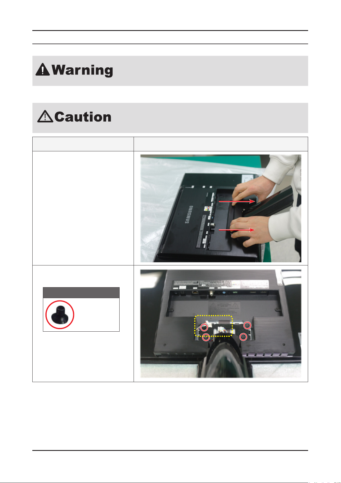
1. Pull and separate the REAR SUB in the
direction of the arrows.
3. Disassembly and Assembly
2. Unfastened the 4 screws, disconnect
the 2 cables, then separate the stand.
Screw
6001-001114
4 EA
3-1

3-2
3. Disassembly and Assembly
Description Photo
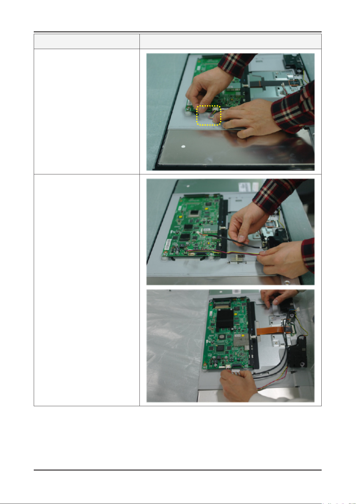
3. Remove the 2 screws from the COVER
REAR, and separate the COVER
FRONT starting from the upper part as
shown in the image.
Screw
6001-001114
2 EA
* Internal locking tabs on the front and
back covers.
4. Turn the product over, and separate the
COVER REAR as shown in the image.
3-3
3. Disassembly and Assembly
Description Photo
5. Remove the tape as shown in the
image.
6. Remove the jacks and cables from
the main board, and separate the
speakers.

3-4
3. Disassembly and Assembly
Description Photo
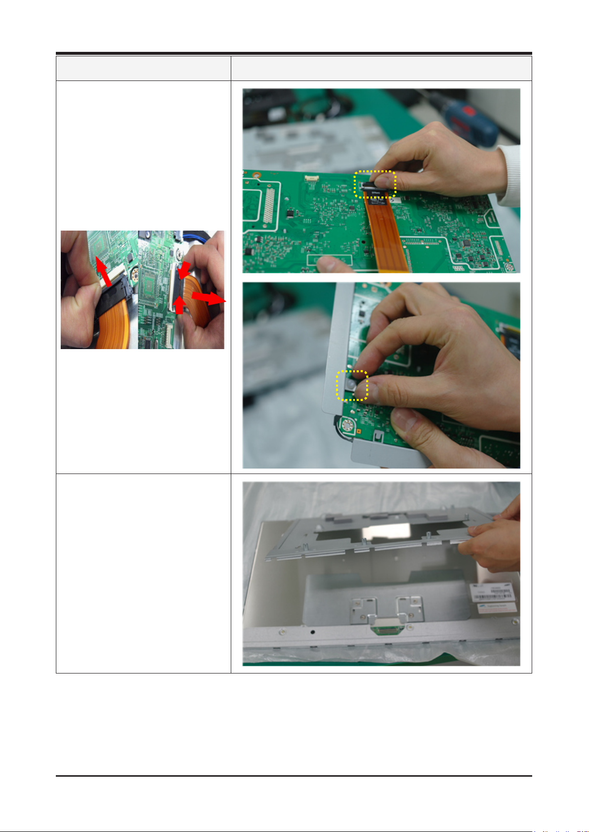
7. Remove the LVDS cable.
* When you reassemble, be careful not
to reverse LVDS cable. The direction
of the cable is printed on it. (‘Panel’,
‘Main’)

3-5
3. Disassembly and Assembly
Description Photo
8. Remove the 4 screws, and separate
the main board.
Screw
6003-000264
4 EA
3-6
3. Disassembly and Assembly
Description Photo
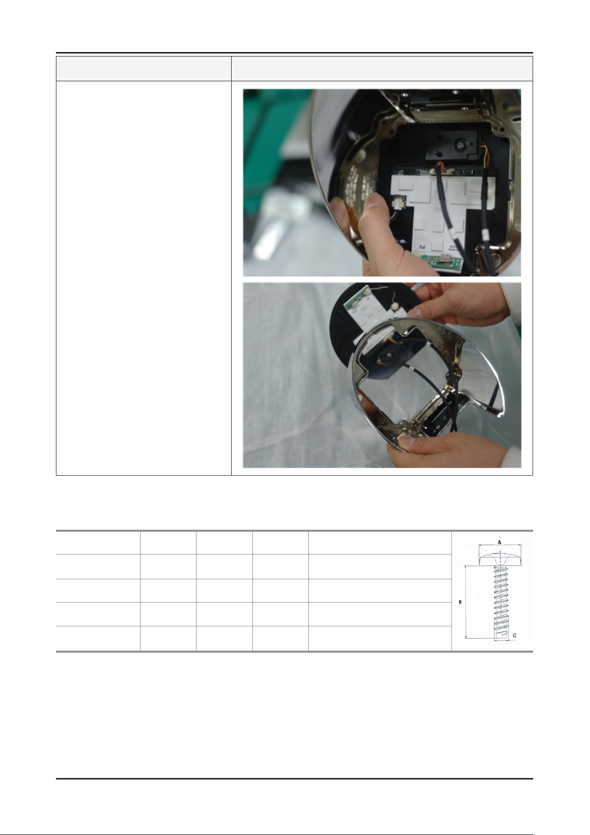
9. Remove the LVDS cable. Then remove
the HOLDER from the main board
and BRACKET AV, and separate the
BRACKET AV.
* New type of LVDS connector applied
to 11’ model.(Double locking)
1. Flip up the locking tab on top of the
connector.
2. Squeeze the edge of the connector
to release the second tab lock and
gently pull the connector away.
10. Separate the BRACKET PCB.

3-7
3. Disassembly and Assembly
Description Photo
11. Separate the COVER STAND REAR.
12. Remove the 4 screws, and separate
the HINGE and STAND NECK.
Screw
6003-001374
4 EA

3-8
3. Disassembly and Assembly
Description Photo
13. Separate the STAND MIDDLE.
14. Remove the 4 screws from the STAND
BOTTOM.
Screw
6003-001785
4 EA
3-9
3. Disassembly and Assembly
Description Photo
15. Separate the STAND TOP.
※ Reassembly procedures are in the reverse order of disassembly procedures.
Screw Size
Code No. A (mm) B (mm) C (mm) Q’ty
6001-001114 8 6 4 6 EA
6003-000264 6 6 3 4 EA
6003-001374 8 12 4 4 EA
6003-001785 8 8 4 5 EA

1. Precautions
1. Precautions
1-1. Safety Precautions
Follow these safety, servicing and ESD precautions to prevent damage and to protect against potential hazards such as
electrical shock.
1-1-1. Warnings
For continued safety, do not attempt to modify the circuit board.1.
Disconnect the AC power and DC power jack before servicing.2.
1-1-2. Servicing the LCD Monitor
When servicing the LCD Monitor, Disconnect the AC line cord from the AC outlet.1.
It is essential that service technicians have an accurate voltage meter available at all times. Check the calibration of this 2.
meter periodically.
1-1-3. Fire and Shock Hazard
Before returning the monitor to the user, perform the following safety checks:
Inspect each lead dress to make certain that the leads are not pinched or that hardware is not lodged between the 1.
chassis and other metal parts in the monitor.
Inspect all protective devices such as nonmetallic control knobs, insulating materials, cabinet backs, adjustment and 2.
compartment covers or shields, isolation resistorcapacitor networks, mechanical insulators, etc.
Leakage Current Hot Check (Figure 1-1):3.
Do not use an isolation transformer during this test.
Use a leakage current tester or a metering system that complies with American
National Standards Institute (ANSI C101.1, Leakage Current for Appliances), and
Underwriters Laboratories (UL Publication UL1410, 59.7).
(READING SHOULD)
NOT BE ABOVE 0.5mA
DEVICE
UNDER
TEST
2-WIRE CORD
*ALSO TEST WITH
PLUG REVERSED
(USING AC ADAPTER
PLUG AS REQUIRED)
TEST ALL
EXPOSED METAL
SURFACES
LEAKAGE
CURRENT
TESTER
EARTH
GROUND
Figure 1-1. Leakage Current Test Circuit
With the unit completely reassembled, plug the AC line cord directly into a 120V AC outlet. With the unit’s AC switch rst 4.
in the ON position and then OFF, measure the current between a known earth ground (metal water pipe, conduit, etc.)
and all exposed metal parts, including: metal cabinets, screwheads and control shafts.
The current measured should not exceed 0.5 milliamp.
Reverse the power-plug prongs in the AC outlet and repeat the test.
1-1
1-2
1. Precautions
1-1-4. Product Safety Notices
Some electrical and mechanical parts have special safetyrelated characteristics which are often not evident from visual
inspection. The protection they give may not be obtained by replacing them with components rated for higher voltage,
wattage, etc. Parts that have special safety characteristics are identied by on schematics and parts lists. A substitute
replacement that does not have the same safety characteristics as the recommended replacement part might create
shock, re and/or other hazards. Product safety is under review continuously and new instructions are issued whenever
appropriate.
1-2. Servicing Precautions
An electrolytic capacitor installed with the wrong polarity might explode.
Before servicing units covered by this service manual, read and follow the Safety
Precautions section of this manual.
Note: If unforeseen circumstances create conict between the following servicing precautions and any of the safety
precautions, always follow the safety precautions.
1-2-1 General Servicing Precautions
Always unplug the unit’s AC power cord from the AC power source and disconnect the DC Power Jack before attempting 1.
to: (a) remove or reinstall any component or assembly, (b) disconnect PCB plugs or connectors, (c) connect a test
component in parallel with an electrolytic capacitor.
Some components are raised above the printed circuit board for safety. An insulation tube or tape is sometimes used. 2.
The internal wiring is sometimes clamped to prevent contact with thermally hot components. Reinstall all such elements
to their original position.
After servicing, always check that the screws, components and wiring have been correctly reinstalled. Make sure that the 3.
area around the serviced part has not been damaged.
Check the insulation between the blades of the AC plug and accessible conductive parts (examples: metal panels, input 4.
terminals and earphone jacks).
Insulation Checking Procedure: Disconnect the power cord from the AC source and turn the power switch ON. 5.
Connect an insulation resistance meter (500 V) to theblades of the AC plug.
The insulation resistance between each blade of the AC plug and accessible conductive parts (see above) should be
greater than 1 megohm.
Always connect a test instrument’s ground lead to the instrument chassis ground before connecting the positive lead; 6.
always remove the instrument’s ground lead last.
 Loading...