

Samsung SVR-1680, SVR-3200, SVR-1660, SVR-1645, SVR-960 User Manual
...
User Manual
0

User Manual
1
Introduction
Thank you for choosing Samsung DVR products.
This is the user manual for SVR-3200, SVR-1680, SVR-1660, SVR-1645, SVR-960, SVR-945.
Before installing or operating thi s product, please f amiliarize yoursel f with this user manu al and
other manuals referenced by this manual.
This user manual and the software and hard ware descri bed here are protec ted by the copyrig ht
law. Therefore, with the exception of copying for general use wi thin the copyright l aw, copying
and reprinting the user manual, either partially or in its entirety, or translating it into another
language without the consent of Samsung Techwin, Inc. is prohibited.
This specification may be changed without prior notice for improvement of product performance.
Product warranty and limits of responsibility
The manufacturer does not assume any other responsibility concerning the sale of this product
and does not delegate any right to a third party to take any responsibility on its behalf. Product
warranty does not cover cases of accide nts, negli gence, alter ation, mi sus e or abus e. In additi on,
no warranty is offered for any attachments or parts not supplied by the manufacturer.
The warranty period for this product will be for 2 years from the date of purchase. The following
cases are not covered by the warranty and payment is required for repairs.
Malfunction due to negligence in handling by the user
Deliberate disassembly and replacement by the user
Connection of an improper power supply
Malfunction caused by natural disasters (fire, flood, etc.)
Replacement of expendable parts (HDD, FAN, etc.)
※ Warranty period of HDD and Fan is one year after purchase.
Warranty only refers to the warranty covering products that have been paid for.
After expiration of the warranty period (2 years), examination and repair will be provided for a
fee. Even during the warranty period, repair and examination of items outside the preceding
warranty scope will require a payment.

User Manual
2
This product is not for exclusive use of crime prevention but for assistance unit such as
a fire or theft. Therefore, we never take any responsibility for the damage from any
incident.
Various experience and technical is needed for installation of this product and an amateur
installation might cause fire, electric shock, and defect. All installation operations should be
performed by the agency you purchased this product from.
This manual is authored SVR-1680, SVR-1660 according to firmware version 1.0.8, SVR-1645,
SVR-960, SVR-945 according to firmware version 1.1.4
Content of this manual can differ by Firmware or Software upgrade, and standard and
appearance of product is changeable partly without pri or notice to users.

User Manual
3
Contents
Chapter 1. Safety Cautions............................................................ 7
1.1 Explaining the Symbols................................................................................................ 7
Chapter 2. Summary..................................................................... 10
2.1 Features..................................... .................................... .................................... ........ 10
Chapter 3. Product Description................................................... 13
3.1 Front part.............. ... ..... ... ... ... .. ... ...... ... .. ... ... ... ..... ... ... ... .. ...... ... ... .. ... ... ..... ... ... ... .. ... ..... 14
3.2 Rear Part............................ ... .. ... ... ... ..... ... ... ... .. ... ...... ... .. ... ... ...... .. ... ... ... .. ...... ... .. ... ... .. 16
3.3 OSD MENU structure.............................................................. ................................... 17
3.4 Function Menu............................................................................................ ................ 18
3.5 Factory setting...... ... ... .. ... ...... .. ... ... ... ... ..... ... ... .. ... ... ...... .. ... ... ... ..... ... ... ... .. ... ...... .. ... ... .. 18
Chapter 4. Monitoring................................................................... 24
4.1 Main Screen..................................... ... .. ...... ... .. ... ... ...... .. ... ... ... .. ...... ... ... .. ... ... ...... .. ... .. 24
4.2 Single image in full screen........................... .................................... ........................... 24
4.3 Multi Screen ............................................................................................................... 24
4.4 User Sequence........................................................................................................... 24
4.4.1 Basic System Mode..................................................................................... ........ 25
4.4.2 User Sequence Mode.......................................................................................... 25
4.5 Event Screen.............................................................................................................. 26
4.6 Screen Zoom..... ... ... ... .. ...... ... .. ... ... ... ..... ... ... ... ... .. ...... ... .. ... ... ..... ... ... ... ... .. ...... ... .. ... ... .. 27
4.7 Pause Live screen............................... .................................... ................................... 27
4.8 PTZ Control.................................................... .................................... ........................ 27
4.8.1 Pan/Tilt................................................. ............................................................... 28
4.8.2 Zoom/Focus ................... .................................... .................................... ............. 28
4.8.3 Load Preset............................... ... .. ...... ... ... .. ... ...... .. ... ... ... .. ...... ... ... .. ... ... ..... ... ... .. 29
4.8.4 Save Preset.................... .. ... ... ... ... ..... ... ... ... .. ...... ... .. ... ... ... ..... ... ... ... .. ... ...... .. ... ... .. 29
4.8.5 Auxiliary On ... ... ... .. ... ...... .. ... ... ... ..... ... ... ... ... ..... ... ... .. ... ... ..... ... ... ... ... ..... ... ... .. ... ..... 29
4.8.6 Auxiliary Off ... ... ... .. ...... ... .. ... ... ... ..... ... ... ... ... ..... ... ... .. ... ...... .. ... ... ... ..... ... ... ... .. ...... .. 29
4.9 Screen Lock.................................................................................................................... 29

User Manual
4
Chapter 5. Playback...................................................................... 30
5.1 Playback................................................ ..................................... ................................ 30
5.1.1 Playback with Main Screen (16/9 division screen)...... .................................... ..... 30
5.1.2 Playback Functions............................................................................................. 30
5.2 Search............................................................................................................................. 31
5.2.1 Time Search.............................. ... .. ...... ... .. ... ... ... ..... ... ... ... ... .. ...... ... .. ... ... ..... ... ... .. 31
5.2.2 Calendar Search ................................................................................................. 32
5.2.3 Event Search....................................................................................................... 33
5.2.4 Thumbnail Search . .. .................................. . . . . . . . . . . ................................................ 33
5.3 Copy..................................................................................................... ........................... 34
5.3.1 CD/DVD .. ............................................................................................................ 34
5.3.2 RE4........................................................................................................... .......... 36
5.3.3 AVI......................................................................................... .............................. 37
Chapter 6. Configuration.............................................................. 39
6.1 Record Setup............................................................................ ...................................... 39
6.2 System Time Setup... .................................... .................................... .............................. 39
6.2.1 Configuring System Time ............... ... ... ... .. ...... ... ... .. ... ... ...... .. ... ... ... ..... ... ... .. ... ... .. 40
6.3 Camera Setup................................................................................................................. 41
6.3.1 Configuring Camera Setup .. ... ... ... .. ...... ... ... .. ... ...... .. ... ... ... ..... ... ... ... .. ...... ... .. ... ... .. 42
6.4 Quick Recording Setup (Quick Setup)................................. ............................................ 43
6.4.1 Configuring Quick Recording Setup .................................................................... 44
6.5 Recording Schedule Setup.............. ... ...... .. ... ... ... .. ...... ... ... .. ... ... ..... ... ... ... ... ..... ... ... .. ... ... .. 44
6.5.1 All Channels........................................................................................................ 45
6.5.2 Individual Channels...................... .. ... ... ... ... ..... ... ... .. ... ... ...... .. ... ... ... ..... ... ... .. ... ... .. 45
6.6 Configuring Event Recording........................................................ ................................... 46
6.6.1 Event Source Setup............................................................................................. 46
6.6.2 Configuring Event Recording for All Channels............................ .............................. 47
6.6.3 Manual Recording Setup.......................................................................................... 49
6.7 Audio & Misc. Setup............. ... ..... ... ... ... ... .. ... ...... .. ... ... ... ... ..... ... ... ... .. ... ...... .. ... ... ... .. ... ..... 50
6.7.1 Audio......................................................................................................................... 50
6.7.2 Audio Mix.................................................................................................................. 51
6.7.3 Record No Video....................................... ... .. ...... ... ... .. ... ...... .. ... ... ... ..... ... ... ... .. ...... .. 51
6.8 Monitor Setup................................................... .................................... ........................... 51

User Manual
5
6.9 Event Setup..................................................................................................................... 53
6.9.1 Event............................. ... ... ..... ... ... ... .. ... ...... .. ... ... ... ... ..... ... ... ... .. ...... .. ... ... ... ... ..... ..... 53
6.9.2 Text........................................................................................................................... 55
6.9.3 D-I/O .. ... ...... .. ... ... ... ... ..... ... ... .. ... ...... ... .. ... ... ... ..... ... ... ... .. ... ...... ... .. ... ... ..... ... ... ... .. ........ 56
6.9.4 Event Action......................... .. ...... ... ... .. ... ... ...... .. ... ... ... ..... ... ... .. ... ... ...... .. ... ... ... .. ...... ..57
6.9.5 Network......................... ... ... .. ... ... ...... .. ... ... ... .. ...... ... ... .. ... ...... ... .. ... ... ... ..... ... ... .. ... ..... 58
6.9.6 xDSL................... ... ... ..... ... ... .. ... ... ...... .. ... ... ... .. ...... ... ... .. ... ... ...... .. ... ... ... .. ... ...... .. ... ..... 59
6.9.7 DDNS......................... ... ... ... .. ...... ... ... .. ... ...... .. ... ... ... ... ..... ... ... .. ... ... ...... .. ... ... ... ..... ..... 60
6.9.8 NTP............................... ... ... ... .. ...... ... .. ... ... ... ..... ... ... ... .. ...... ... .. ... ... ... ..... ... ... ... .. ... ..... 64
6.9.9 Serial............................. ... ... ..... ... ... ... .. ...... ... .. ... ... ... ..... ... ... ... ... .. ...... .. ... ... ... ..... ........ 65
6.10 System Setup................................................. .................................... ........................... 66
6.10.1 Setup.......... ... ... ... ... ..... ... ... ... .. ...... ... .. ... ... ... ..... ... ... ... .. ... ...... .. ... ... ... ..... ... ... ... .. ... ..... 66
6.10.2 Disk Setup.. ... ... ... ..... ... ... ... .. ... ...... ... .. ... ... ...... .. ... ... ... .. ...... ... .. ... ... ... ..... ... ... ... .. ...... .. 68
6.10.3 Security......................................... ... .. ... ... ... ..... ... ... ... .. ... ...... .. ... ... ... ..... ... ... ... ... .. ..... 70
6.10.4 Time Schedule........................................................................................................ 72
6.10.5 Special Time........... .. ... ... ... ..... ... ... ... .. ... ...... .. ... ... ... ..... ... ... ... .. ... ...... ... .. ... ... ... ..... ... .. 73
6.11 Exit................................ .. ... ... ..... ... ... ... ... .. ...... ... .. ... ... ...... .. ... ... ... .. ...... ... ... .. ... ... ............. 74
Chapter 7. Web Viewer................................................................. 76
7.1 System Requirements..................................................................................................... 76
7.2 LOGIN.... .................................... ..................................................................................... 76
7.3 Connection User setup.................................................................................................... 77
7.4 Supported Browser.......................................................................................................... 78
7.5 Monitor..................................................... .................................... ................................... 78
7.5.1 Screen Partition & Image Movement................................................................... 78
7.5.2 Moving Playback..................................... ... .. ...... ... .. ... ... ... ..... ... ... ... .. ... ... ..... ... ... .. 79
7.5.3 Channel On/Off ................... ... ... .. ...... ... ... .. ... ... ...... .. ... ... ... ..... ... ... ... .. ... ...... .. ... ... .. 79
7.5.4 Sensor indication................................................................................................. 80
7.5.5 Relay operation................................................................................................... 80
7.5.6 Microphone use.............. .. ... ... ..... ... ... ... ... ..... ... ... ... .. ...... ... .. ... ... ...... .. ... ... ... .. ...... .. 80
7.5.7 Event Data........................................................................................................... 81
7.5.8 Video Recording & Video Storage ...................... ... .. ...... ... .. ... ... ...... .. ... ... ... ..... ... .. 81
7.5.9 PTZ Use......................................... ..................................................................... 82
7.5.10 Audio Use............................................................................................................ 83
7.5.11 Image Channel Close........................ ... ..... ... ... ... ... ..... ... ... .. ... ...... ... .. ... ... ... ..... ... .. 83

User Manual
6
7.6 Playback ......................................................................................................................... 83
7.6.1 Screen Division & Channel Change ..................................................... ............... 8 4
7.6.2 Image Recording.......................... .. ...... ... ... .. ... ...... .. ... ... ... .. ...... ... ... .. ... ...... .. ... ... .. 84
7.6.3 Print................................................................................................................ ..... 84
7.6.4 Move to Web Monitor .......................................................................................... 84
7.6.5 Channel On/Off ................... ... ... .. ...... ... ... .. ... ... ...... .. ... ... ... ..... ... ... ... .. ... ...... .. ... ... .. 85
7.6.6 Recording Duration & Recording Size Check...................................... ................ 85
7.6.7 Calendar Search ................................................................................................. 85
7.6.8 Playback Toolbar................................................................................................. 85
Trouble Shooting.......................................................................... 87
Compatible HDD List.................................................................... 89
Compatible Media List.................................................................. 89
Specification ................................................................................. 89
Dimensions ................................................................................... 93

User Manual
7
Chapter 1. Safety Cautions
1.1 Explaining the Symbols
Warning
Refers to information users need to know in order to prevent serious injury or
death.
Before installation
9 Verify the supplied voltage (AC100V~AC240V) before connecting to the power
supply.
9 Make sure the power su pply is off before installation.
9 Do not install in a ver y humi d env iro nmen t. Doin g so ma y caus e an elec tric shoc k or
fire.
9 Make sure ground line is connected to reduce electric shock risk.
During operation
9 Do not open the product cover except by qualified personnel or system installer.
Opening the product cover m ay cause an electric shock.
9 Do not plug multiple appliances into a single power outlet. Doing so may cause fire.
9 Do not place dishes holding water or heavy objects on the product. Doing so may
cause a malfunction.
9 Do not use in areas where inflammable substances such as propane gas or
gasoline or high amount of dust is present. Doing so may cause an explosion or fire.
9 Do not touch the powe r line with a wet hand. Doing so may cause an electric shock.
9 Do not insert a hand into the opening of the DVD. Doing so may cause an injury.
9 Make sure conductive materials do not enter the cooling ventilator opening.
9 Do not apply excessive force when pulling on the power cord. Damaging the cord
may cause an electric shock or fire.
9 Improper replacement of the built-in battery by other types of batteries may cause
explosion. The batter must be replaced by the same battery type. Also, expired
batteries may cause polluti on and must be disposed of with care.
9 Do not place the battery in fire or in extreme heat. Also, do not dissect or
disassemble the battery.
9 Recharge the batteries for the remote controller.
Dismantling and cleaning

User Manual
8
9 Do not dismantle, repair or modify the product deliberately. Doing so may cause a
damage, an electric shock or an injury.
9 Do not use water, paint thinner or organic solvent for cleaning the product exterior.
Doing so may cause a malfunction or an electric shock. Use a dry cloth to clean the
exterior.
During installation
9 For adequate ventilation, install the product with at least 15cm of space between the
cooler and the wall surface.
9 To prevent falling, install the product on a flat area . Dropping the product may
cause an injury or a malfunction.
9 Avoid areas exposed to dir ect exposure to sun light or excessive heat since the y
may cause deformation or a malfunction.
9 If a camera is installed whi le the DVR is being recorde d, image in another channel
may be disrupted. Starting the storage after the camera has been installed is
recommended.
During use
9 Make sure the product is not exposed to concussions or shaking during usage or
movement.
9 Do not move, throw or expose to excessive physical concussion during usage.
9 Installing additio nal unapproved hard disk drives may result in abnormal operati on.
Inquire at the agency of purchase before installing additional hard disk drives.
9 Product warranty will not cover malfunctions due to additional installation of
unapproved hard disk drives.
9 This product is a supplementary rather than primary means for preventing fire and
theft. Our company is not responsible for accidents or damage that may occur.
Samsung Techwin cares for the environment at all product
manufacturing stages to pr eserve the environment, and is taking a
number of steps to provide customers with more environmentfriendly products. The Eco mark represents Samsung Techwin s will
to create environment-friendly products, and indicates that the
product satisfies the EU RoHS Di rective.
Caution
Provides information users need to know in order to prevent minor
injury or product damage.
User Manual
9
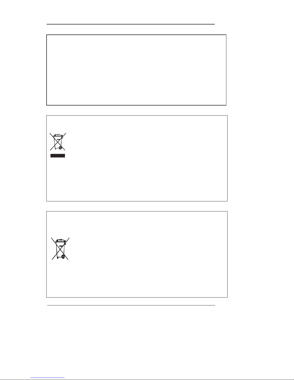
Correct Disposal of This Product
(Waste Electrical & Electronic Equipment)
(Applicable in the European Union and other European countries with separate
collection systems.) This markin g shown on the pr oduct or its literat ure, indic ates that it
should not be disposed wit h other household wastes at the end of its working life. To
prevent possible harm to the environment or human health from uncontrolled waste
disposal, please separate thi s from other types of wastes and recycle it responsibly to promo te the
sustainable reuse of mater ial resources. Household users shoul d contact either the retailer where
they purchased this product, or their local government office, for details of where and how they can
take this item for environmentally safe re cycling. Business users should contact their supplier a nd
check the terms and conditions of the purchase contract. This product should not be mixed with
other commercial waste s for disposal.
Correct Disposal of Batteries in this Product
(Applicable in the European Union and other European countries with
separate battery return systems.)
This marking on the battery, manual or packaging indicates that the batteries in this
product should not be dispos ed of with other household waste at the end of their
working life. Where marked, the chemical symbols Hg, Cd or Pb indi cate that the
battery contains mercury, cadmium or lead above the reference levels in EC
Directive 2006/66. If batt eries are not properly disposed of, these substances ca n cause harm to
human health or the environment. To protect natural resources and to promote material reuse,
please separate batteries fr om other types of waste and recycle the m th r ou g h you r lo cal , fr e e ba tt e ry
return system. The rechargeable battery incorporated in this product is not user r eplaceable.
For information on its replacement, please contact your service provider.
FCC Compliance Statement
NOTE: This equipment has been tested and found to comply with the limits for a Class A digital
device, pursuant to part 15 of the FCC Rules. These limits are designed to provi de reasonable
protection against harmful interference when the equipment is operated in a commercial
environment. This equipment generates, uses, and can radiate radio frequency energy and, if not
installed and used in accordance with the instruction manual, may cause harmful interference to
radio communications. Ope ration of this equipmen t in a residential area is likely to cause harmful
interference in which cause the user will be required to correct the interference at his own
expense.

User Manual
10
Chapter 2. Summary
2.1 Features
Monitoring Screen
The monitoring screen supports vivid, high-definition live visual feed from each channel and
provides multiple screens.
Real-time MPEG-4 visual output (480 frames)
Multiple split-screen monitoring mode s
SVR-3200/1680/1660/1645: Single, 4, 9, 10, 16
SVR-960/945: Single, 4, 9
Automatic Screen Switching (AUTO)
Supports various monitor output modes
SVR-3200 : 4 Composite , 2 VGA
SVR-3200/1680 : 4 Composite, 1 VA
SVR-1660/1645/960/945 : 2 Composite, 1 VGA
Pan/Tilt, Digital Zoom, PIP (Picture-In-Picture)
The PIP function will be avai lable with a firmware upgrade in the future.
This unit is a digital vi deo r ecor di ng a nd pla ybac k dev ice t o rec ord im ag e and v ideo i npu t
from 32/16/9 channels to i ts built-i n hard disk. The butt ons on th e front of t he unit as well
as the mouse and GUI allow easy setup and operation.
The Samsung SVR series of digit al vide o recor ders (DVRs) pr ovide additio nal safet y and
security to banks, apartment buildings and complexes, government offices as well as
other public, private and com mercial facilities. Recorded high-qualit y video and images
are stored on hard disk for later retrieval or playback. Real time functionality delivers
users with the ability to simultaneously record multiple channels, playback video, and
copy video. A few of the more advanced user-conveniences include moti on detection,
Pan/Tilt/Zoom controls (PTZ ), password prot ection, real time audio re cording, even t lists,
and log files.

User Manual
11
Audio Recording
This feature supports real-time audio input and recordin g.
Simultaneous recording of 16/9 c hannels audio input in real time
SVR-3200/1680/1600/1645 : Input - 16 channels (4 RCA in rear, 12 D-SUB)
Output - 1 in rear
SVR-960/945 : 9 channels (4 RCA in rear, 5 D-SUB), Output - 1 in rear
Supports simultaneous record in g and playback
Video Recording
The product is capable of stor ing visual image d ata as high resolut ion MPEG-4 files wit h up
to 480 frames per second, as well as pre-emptively initiating recording sequence up to five
seconds prior to an event. Also, the COVERT feature (concealment of visual data) is
implemented to protect the user's privacy.
High quality real-time MPEG-4 recording
Three screen resolution levels for improved control over data size
Multi-recording function for manual and schedule events
Simultaneous recording/playback/backup/networking operation capacity
Easily accessible options for channel-specific resolution and motion detection
ranges
Per-second frame rates (up to 30 frames per channel) are user customizable
SVR-3200 : Half D1 (704x240) 960fps
SVR-1680 : D1 (704x480) 480fps
SVR-1660/1645 : CIF (352x240) 480fps
SVR-960/945 : CIF (352x240) 270fps
Manual and schedule recording function

User Manual
12
Video loss detection function
Event (Sensor, D-I/O, Video loss, Motion detection, Text) log
Each channels can support pre-emptive recording seque nces up to 5 seconds
prior to an actual event
Search/Playback
Various search and playback options are offered for the user’s convenience.
Playback by time, date and channel
Mouse interface increases data searchability
Forward/backward search functions in pause
Playback by event (Sensor, Video loss, Motion detection and Text) log
Remote controller and Jog/Shuttle function further improve searching
(The SVR-960/945 models do not support Jog/Shuttle.).
Full-frame playback (available in SVR-3200/1680/1660 only)
Data Storage
A hard disk is included in the product for the purpose of data storage. If the user desires, the
recorded data can be stored to DVD-R, CD-R or USB.
A built-in hard disk has been provided as a basic supply item
Multiple portable data storage media are supported: DVD-R, CD-R and USB
※ Refer to the appendix on the back of the manual regarding the type of
compatible media.
Hard disk expansion device(External recording device) : SVS-5E (Option as
exclusive device) External hard disk expansion is supported with SVS-5E
(Available for purchase)
Networking
The product supports LAN, xDSL an d such networking capabilities. Combi ned with the PC
interface client, the core features of the device can be easily controlled from a distance.

User Manual
13
E-mails can be sent via TCP/IP or DHCP upon an event trigger
Remote live visual fe ed (Single or 4 Partition)
PC playback, storage, search and DVR control functions via Network Viewer
Remote recording, search and playback scheduling functions
Support 10/100Mbps Ethernet/xDSL
Multiple DVR connection
Others
User-friendly GUI and mouse interface
Simplified firmware upgrades with USB
Visual data recording and backup to USB
Supports PTZ control (SPEED DOME) and PRESET function
Multilingual support : Korean, English, Italian, Spanish, Japanese, etc.
Single remote controller to control 16 DVRs
Chapter 3. Product Description
User Manual
14
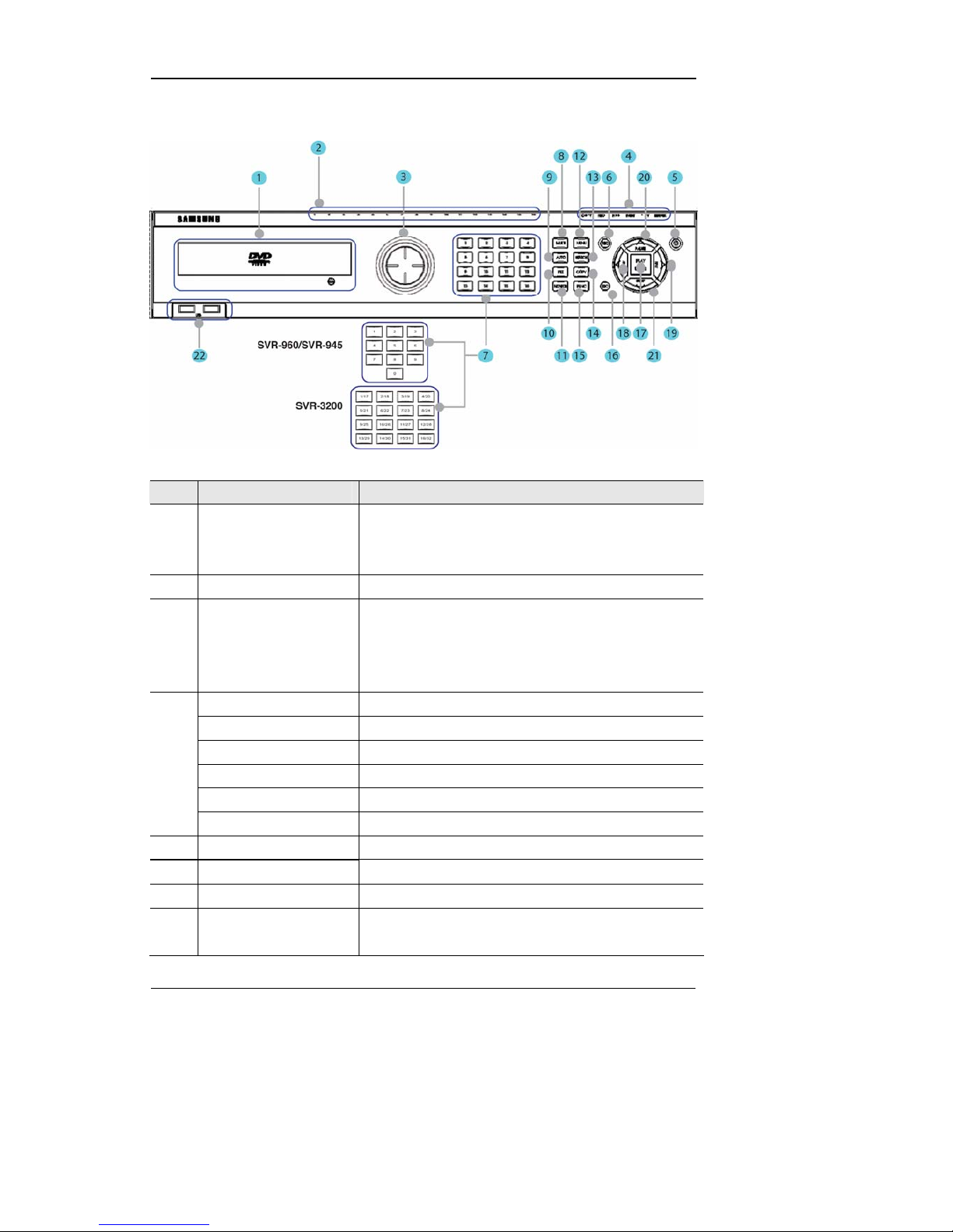
3.1 Front part
No. Classification Function
1 DVD-Multi for copying
For copying recorded video and images to DVD/CD
optical media. (Exception: The SVR-945 uses an
external copy device.)
2 Channel LED Shows the data input and event operation st a tus
3 JOG/SHUTTLE
Jog can adjust setting values, control the STEP
function, navigate through the menu, and adjust the
playback speed and direction. Shuttle controls PTZ.
(The SVR-960/945 does not support Jog/Shuttle.)
REC lamp Lit when recording.
HDD lamp Lit when HDD is working.
NETWORK lamp Lit when network is connected.
EVENT lamp Lit when an event is detected.
COPY lamp Indicates copying operation.
4
PLAY lamp Lit when copying..
5 Power button Turns on or off the device.
6 REC button Starts or stops manual recording
7 Channel button Selects channel in live feed or playback
8 MULTI Changes split-screen sections for live video feeds or
playback.

User Manual
15
9 AUTO Starts or stops user defined sequences.
10 PTZ Starts or ends PTZ function.
11 MONITOR SVR-3200/1680 : Cycles through from Monitor 1 to 4.
SVR-1660/1645/960/945 : Switches from main and sub
monitor
12 MENU Navigates into the Menu.
13 SEARCH Starts Search mode.
14 COPY Starts Copy mode.
15 FUNC Starts Function mode.
16 ESC button The Escape button navigates up the menu tree and
closes dialog windows.
17 PLAY /ENTER Start play bac k or select an item on the menu.
18
◀/REW
Navigates or selects in the menu, or for playback,
changes the reverse playback speed.
19
▶/FFW
Navigates or selects in the menu, or for playback,
changes the forward playback speed.
20
▲/PAUSE
Navigates or selects in the menu, or for playback,
pauses live or recorded video.
21
▼/STOP
Navigates or selects in the menu, o r for pla yback, st ops
playback.
22 USB1, USB2
USB ports for external devices (mouse, USB memory
stick).
User Manual
16
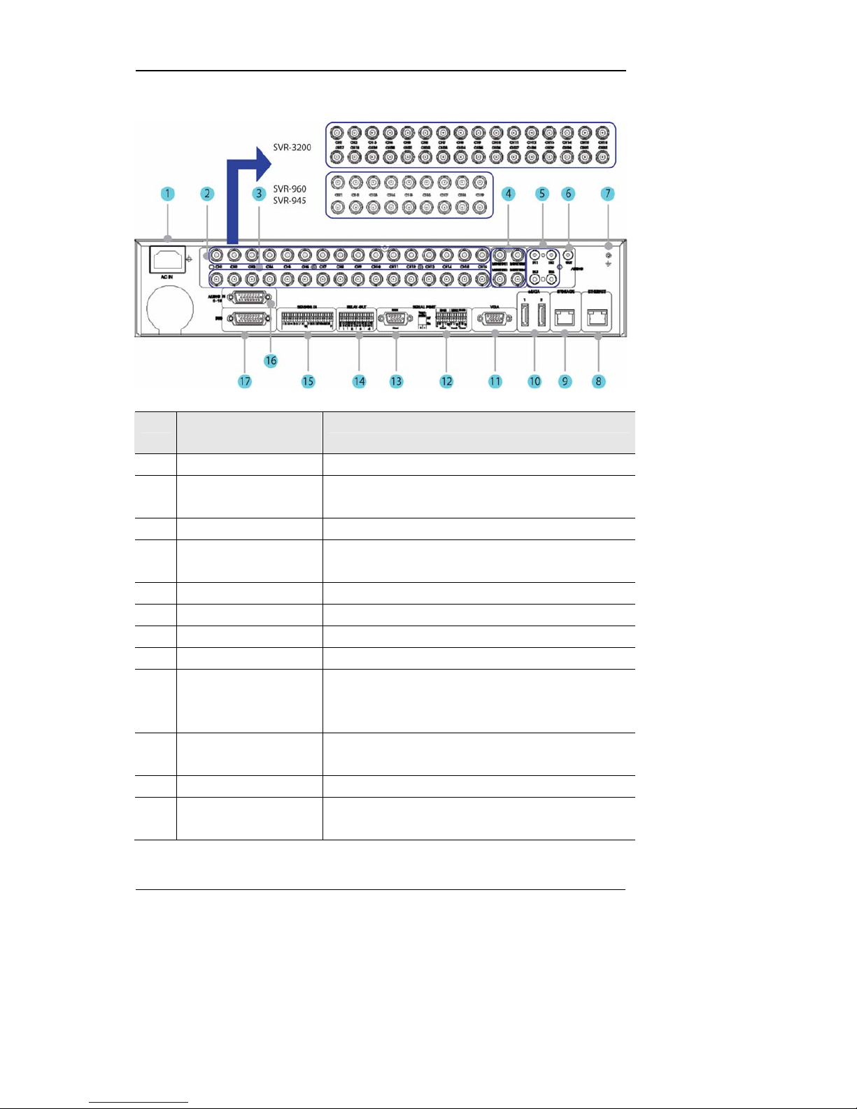
3.2 Rear Part
No. Input/Output terminal
name
Function
1 POWER IN Socket for AC 100V ~ AC 240V power cord.
2 CH1 ~ 32 (16/9) Connection terminal for camera BNC input.
SVR-3200: 32 ea., SVR-960/945: 9 ea.
3 LOOP OUT Connection terminal for camera BNC output (loop).
4 MONITOR 1 ~ 4 Connection terminal for monitor BNC output.
SVR-1660/1645/960/945: 1 ~ 2 ea.
5 AUDIO IN(RCA) RCA audio jack for RCA input.
6 AUDIO OUT Audio jack for speaker output.
7 GROUND Ground terminal between DVR and external device.
8 ETHERNET Ethernet port for network connections (RJ-45).
9 STORAGE External storage connection port (Function not supported in
the current version). Only available in the SVR-
3200/1680/1660 models.
10 eSATA Connection terminal for external eSATA HDD or HDD for
backups.
11 VGA OUTPUT Output port for PC monitor.
12
Serial Port (Terminal Block)
RS-232C/485/422
Connection terminal for e x panded controller, speed dome
camera, etc.
User Manual
17
No. Input/Output terminal
name
Function
13 Serial Port (Terminal Block) RS-232C D-SUB connector.
14 RELAY OUT Connection terminal for relay output.
15 SENSOR IN Connection terminal for sensor input.
16 AUDIO IN(D-SUB) Connection terminal for audio out put D-SUB.
17 D-I/O Connection terminal for DIGITAL IN/OUT.
Refer to detailed description for installation & use from “Install Manual”.
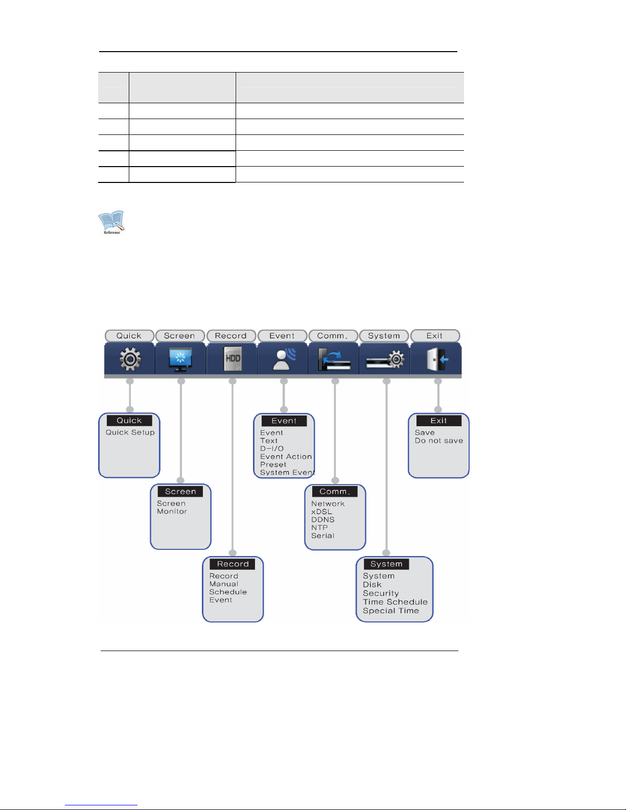
3.3 OSD MENU structure
The menu structure is as shown below. For detailed instructions for config urat ion, please refer to
Chapter 4, 5 and 6.
User Manual
18
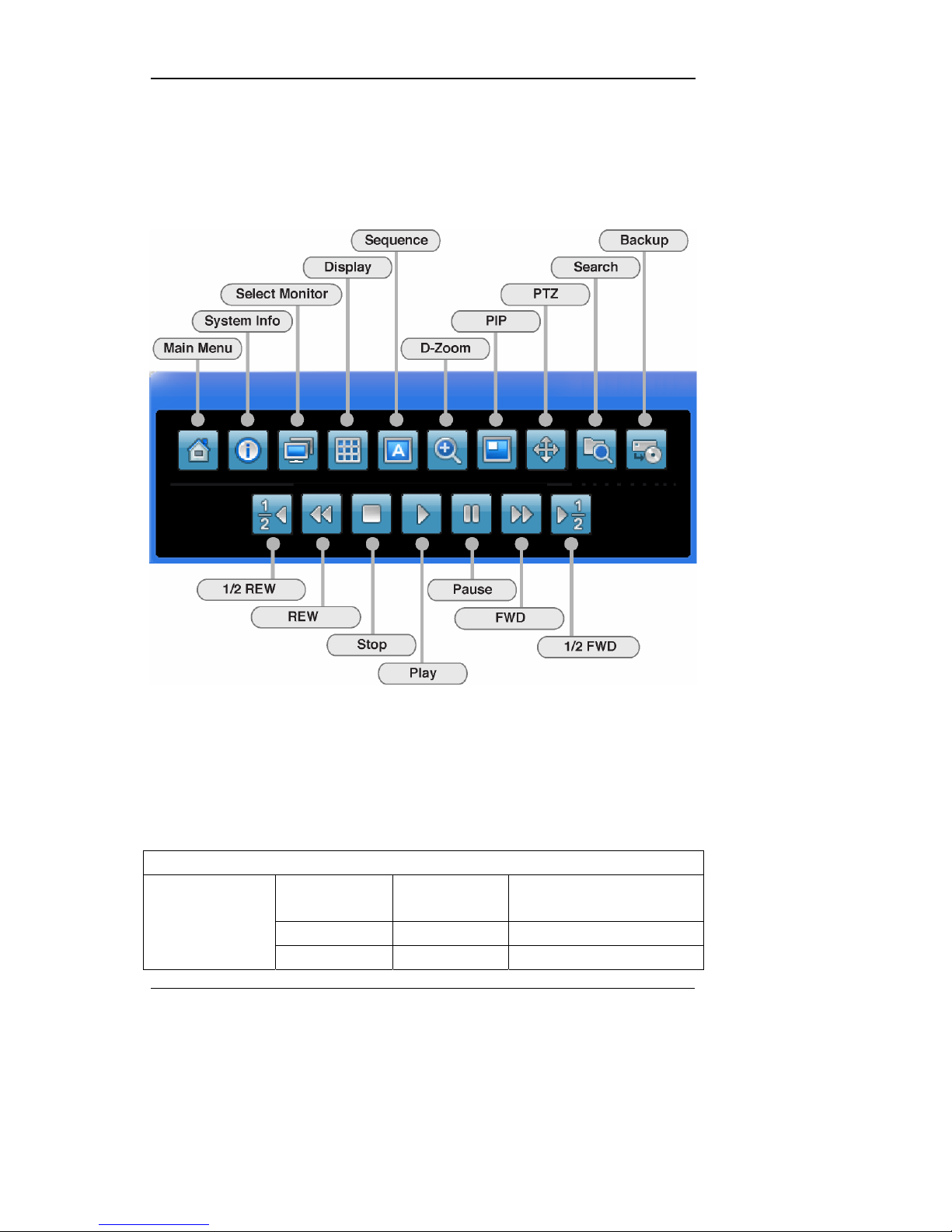
3.4 Function Menu
The function menu allows the users to access an y and all functions an d operations of the product with the
mouse. To execute a particular function, left-click the icon. Also, all functions listed in the function menu
can be executed in full-screen mode. The function menu structure is as shown below.
3.5 Factory setting
To restore factory setting, go to System -> System -> Restore Factor y Setting. A pop-up window saying
"Warning : The system will be reset. Continue with restoring factory default?" will appear. Select "Yes" and
press Enter to restore factory default.
Factory Default
Quick Setup
Schedule
Recording
No Rec.
Speed 1 fps
Quality Q1

User Manual
19
Resolution CIF
UTC 00:00 Dublin
Off
MM/DD/YYYY
Time
Current Time
Language English
Screen Setup
Channel Number Ch 1
Title Cam 1
Activity On
Color Color
AGC Enabled
Brightness 0
Contrast 0
PTZ PTZ Home Off
PTZ Idle Time 5
PTZ Port None
Screen
Address 0
Monitor Number Main Monitor (Monitor 1)
Switch to Event
Screen
Off
Covert Channel All Uncheck
User Sequence All Not Set
SEQ. Dwell Time 5 sec.
Multi Mode 4E Ch 1,3,5,7
VGA Mode 800x600@56Hz
Monitor
Info Level Uncheck remote controller ID
Record Setup
Audio Channel Ch 1
Recording Off
Gain 0
Sync Video
Channel
Ch 1
Audio Mix Mix On
Record
Record No Video Off
Manual Channel Number All

User Manual
20
Macro Disabled
Speed 1 fps
Quality Q1
Resolution CIF
Pre Event 1
Post Event 1
Channel Number All
Schedule Full Time
Macro No Rec.
Speed 1/0.75 fps
Quality Q1
Resolution CIF
Special Time No Rec.
Schedule
Event Recording Off
Channel Number
Type Sensor Off
MD Off
Text Off
Macro Standard
Speed 8 fps
Quality Q3
Resolution CIF
Pre-Event 1
Event
Post-Event 5
Event Setup
Sensor All N.O
MD All
Sensitivity 1
Event
Area Set All
Recording Off
Sync Text With Ch 1
Device Manual
Seek Header Off
Header 1 Header1
Header 2 Header2
Text
Delimiter 0D0A

User Manual
21
Timeout (ms) 1000
Lines 20
Select D-I/O Output D-I/O
Output Ty pe Sensor
Select Action R1
Action Duration 10
Action Source Full Time, Uncheck All
Event Action
Event Acton in
Special Time
Full Time, Disable
Channel Number Ch 1 Preset
Preset Sensor1, Not Set
System Event
Source
Uncheck All System Event
System Event
Method
Uncheck All
Communication
Type Ethernet
DHCP Off
IP addr Current IP
Net Mask Current NM
Gateway Current GW
DNS1 0.0.0.0
Additional DNS 0.0.0.0
Port 4000
Network
Band Width
Limit(Mbps)
0.0
User ID guest
Password *****
xDSL
Status Disconnected
Interval Off
Server www.samsungipolis.com
ID None
Password None
DDNS
Status Not registered
Sync With NTP Off
NTP
NTP Mode Client

User Manual
22
NTP Server Loc. Public
NTP Local Server
IP
0.0.0.0
Interval 1 (Hour)
Serial Number Com1
Device None
Interface RS232
Baud Rate 9600
Parity Bit None
Stop Bit 1
Serial
Data Bit 8
System Setup
Remote
Controller ID
Off
DVR ID 1
DVR Alias DVR0
Playback
Deinterlace
On
Language English
Firmware Update >>
Load/Save
Configuration
>>
Default >>
System
System Log >>
Repeat Record
Mode
On
Warning Lever 45(%)
Block Playback No Block
Disk Manager >>
Disk
Disk Status >>
User Password Off
Password ****
Re-Enter ****
Admin Password Off
Password ****
Security
Re-Enter ****

User Manual
23
Remote Setup Enable
Remote Relay Enable
Weekday Start Mon
Weekday End Fri
Day Start 09:00
Time Schedule
Day End 18:00
Zone 1
00:00 – 00:00
Zone 2
00:00 – 00:00
Zone 3
00:00 – 00:00
Zone 4
00:00 – 00:00
Special Time
Exception Days >>
Save
Save >>
Do not save >>
User Manual
24
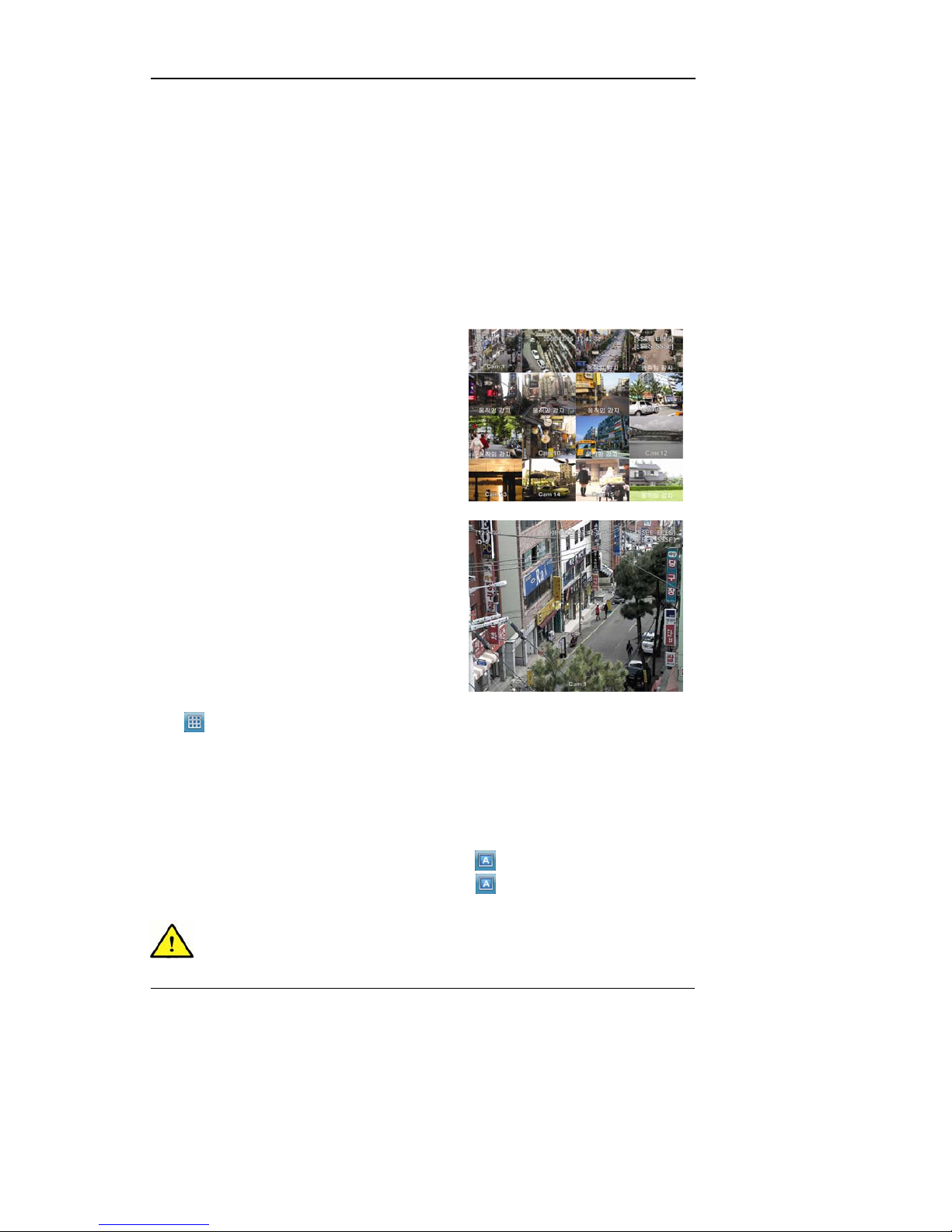
Chapter 4. Monitoring
When turned on, the DVR will display vis ual data from all analog channels on the sc reen in its
monitoring mode. This chapter explains how to use all monitoring modes offered by the DVR.
4.1 Main Screen
- The DVR will turn on when connected with an
adequate power source.
- All LEDs will turn on and off during the bootup
process.
- After bootup, the screen will be displayed in the
16 partition mode. (SVR-960/945 : 9 partition)
※ If passworded, a login window will appear.
4.2 Single image in full screen
- Press the desired channel button or left-click
the desired channel partition.
- Press [MULTI] button or left-click again to return
to the partition screen.
4.3 Multi Screen
- To see several channels simultaneously, press [MULTI] button or left-click Division Mode
in the function menu and select the desired partition mode.
- Pressing [MULTI] will cycle the partition mode (4A, 4B, 4C, 4 E, 9A, 9B, 10A, 16). SVR960/945 support 4A, 4B, 4C, 4E, 9A and 9B partition modes.
4.4 User Sequence
Once all slots in the user sequ ence option has been filled or the desires channels have been
selected, press [AUTO] button on the front sid e or click
in the function menu. To end user
sequence, press [AUTO] button on the front side or click
in the function menu again.
If the user sequence has not been set up, pressing [AUTO] button will not
initiate a user sequence.
User Manual
25
4.4.1 Basic System Mode
- Pressing the [AUTO] button or clicking in the function menu will cause the DVR to
cycle through the set channels.
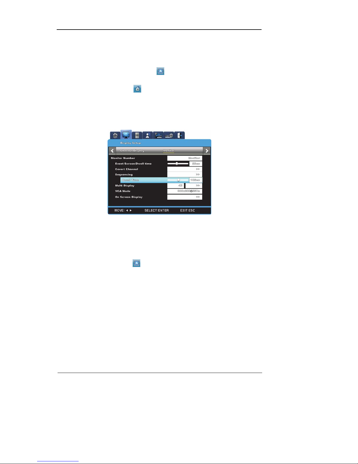
- Press [MENU] button or click
in the function menu to set up sequence period.
- Go to “Screen Setup” from OSD menu.
- Go to “Monitor” under “Screen Setup”, and press [ENTER] button or lef t-cli ck.
- Select “SEQ. Dwell Time” and assign the desired val ue ra ngin g fro m 1 t o 60. W hen s et t o
Off, user sequence view functio n will not operate.
- User sequence mode can be access ed by pressing [AUTO] button from every partition
mode.
- Press [AUTO] button once again to exit from user sequence mode.
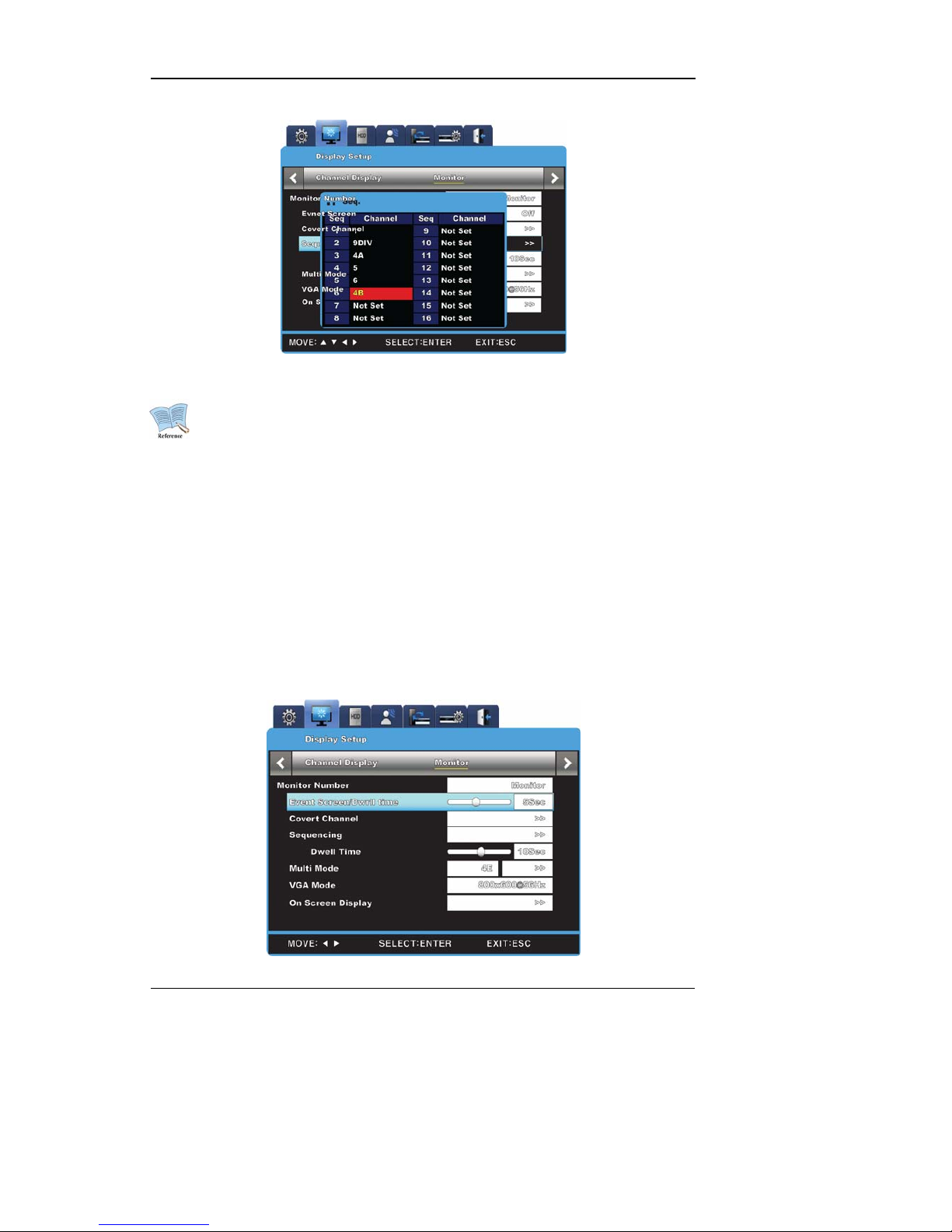
4.4.2 User Sequence Mode
- Press [AUTO] button or click from the function menu.
- To activate user sequence, set “Monitor” to User Sequence in the OSD menu.
User Manual
26
1. User sequence can define up to 16 channels.
2. The example shown above has defined 6 sequences in the following order:
Single (1) Æ Full (16DIV) Æ 4 Partition (4A) Æ Single (5) Æ
Single (6) Æ 9 Partition (9A). SVR-960/945 support only up to 9 partition.
4.5 Event Screen
- A screen may be set to pop up automatically in case of an event trigger.
- The pop-up screen's frequency setting may be set in "Switch to Event Screen" under
"Monitor".
- In case s of multiple event triggers in multipl e channels, the partiti on mode determined by
the number of such channels will be used to display them. For example, if events were
triggered in three separate channels, they will be displayed in the 4 partition mode. To
return to original partition mode, click one of the event screens.
User Manual
27
1. If Switch to Event Screen is set to Off, the Event pop-up function will not
operate.
2. If Switch to Event Screen is set to Keep, the po p-up screen will be displayed
until a button press. To return to the previous screen, press any button.
4.6 Screen Zoom
- In sin gle full-scre en mode, press [FUNC] button, click
, click + and press Enter or left-
click to zoom in on the visual.
- When
is clicked, the screen will zoom in on the center. The zoom area can move
from left to right in 18 steps and from up to bottom in 12 steps.
- Use direction keys to move t he zoom area.
- To return to the previous screen, press Enter or left-click the background.
4.7 Pause Live screen
- Both live visual feed and data playback can be paused momentarily.
- Press [PAUSE] to pause visual feed. Press [PAUSE] button again to return to visual
feed.
4.8 PTZ Control
If a PTZ controller has been c onnected to the DVR and the necessary
protocols have been set in "Serial" menu, real-time manipulation of
PTZ becomes enabled.
To access PTZ functions, press [ PTZ] button on the front side of the
console or press [FUNC] button to cycle through available functions.
The following PTZ controllers are supported:
PTZ, Keyboard Compatible List
모델명 제조사
SDZ160/330, Samsung SPD
Keyboard SCC3000, Samsung SRX-100B
SAMSUNG TECHWIN
BOSCH AutoDome, TC8560X-4
BOSCH
PELCO(P), PELCO(D)
PELCO

User Manual
28
Honeywell 755/655, HRX-2000, ScanDome2
HONEYWELL
Sony EVI-D3x
SONY
VT VPT-4x
VT
AD SpeedDome
AD
SungJin SJ372R1’
SUNGJIN
Samsung SCC641
SAMSUNG ELECTRONICS
Panasonic WV-CS850
PANASONIC
LG GAC-PT2
LG
Keyboard KBD300A, WGI SPD1800/2600
WEBGATE Inc.
Merit-Lilin FastDome
MERIT
Elmo PTC200C
ELMO
Canon VC-C4
CANON
HTC-230S
D-MAX
RVision
RVISION
Elbex
ELBEX
VIDO
VIDO
VICON
VICON
Hunt
HUNT
ORX-1000
SYSMANIA
Fine CRR-1600
LIVEI
Tokina
TOKINA
Kodicom KRE
KODICOM
Nuvico
NUVICO
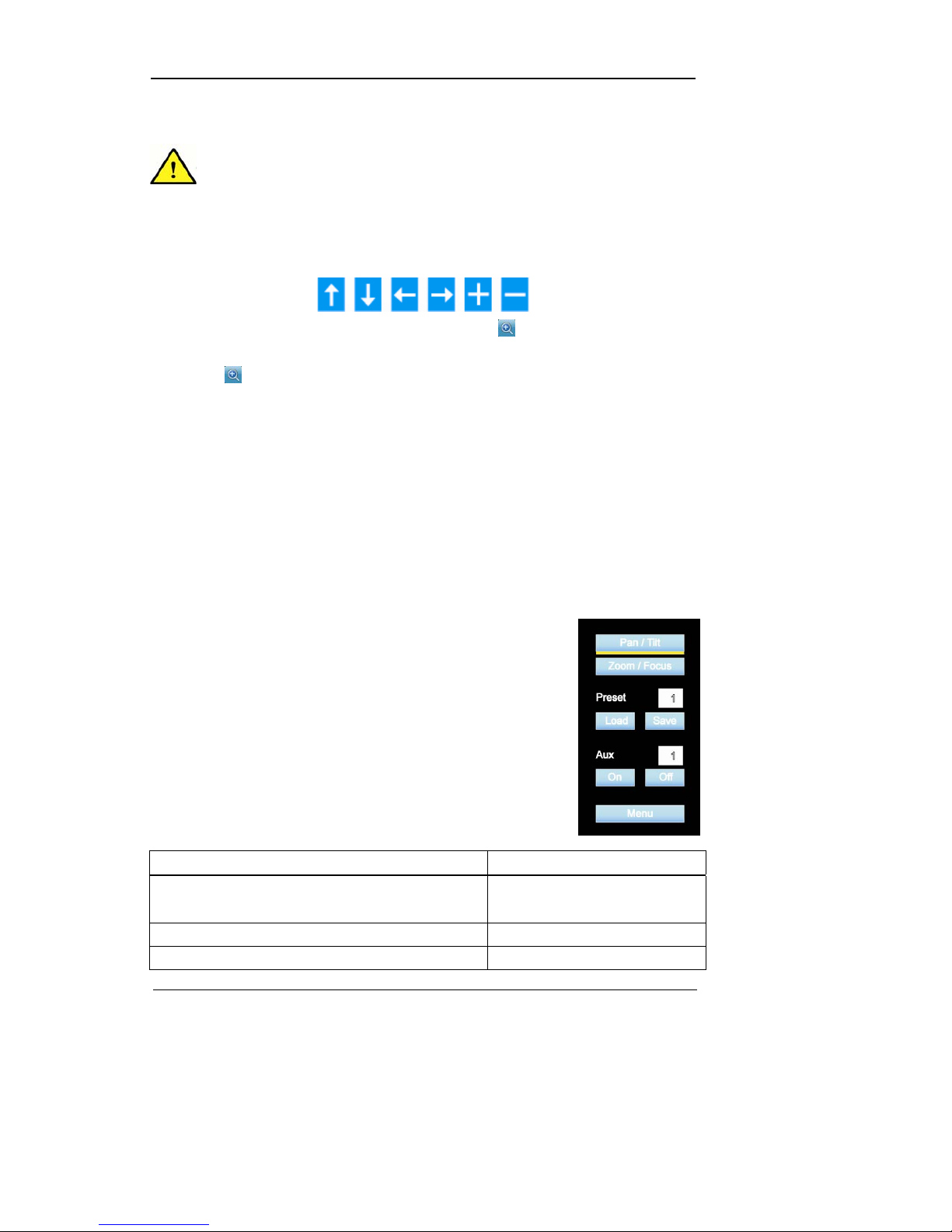
- Go to the channel that needs to be manipulated.
- Press [PTZ] button or click
in the function with th e mouse .
- PTZ menu (Pan/Tilt, Zoom/Focus, Load Preset, Save Preset) will appear
- Select the menu option to be edited and press [ENTER] or left-click.
4.8.1 Pan/Tilt
Used to utilize panning and tilting simultaneously with real-time feed.
- Select Pan/Tilt from PTZ mode.
- Use the left/right direction buttons on the front side of the console or click left/right on the
screen to pan. Use the up/down direction buttons or click up/down on the screen to tilt.
4.8.2 Zoom/Focus
Used to utilize zooming and focusing simultaneously with real-time feed.

User Manual
29
- Select Zoom/Focus from PTZ mode.
- Use the direction buttons on the front side of the console or the mouse wheel to zoom and
focus.
4.8.3 Load Preset
Used to switch to a preset position from real-time monitoring mode.
- Select the desired Preset setting using the up/down buttons or the mouse wheel.
- Once a preset mode has been selected, select Load and press [ENTER] or left-click to
load.
-
4.8.4 Save Preset
Used to set a new preset position from real-time monitoring mode.
- Move the camera to the desired position using the ‘Pan/Tilt’ and ‘Zoom/Focus’ menu.
- Select the desired Preset setting slot using the up/down buttons or the mouse wheel.
- Once selected, select Save and press [ENTER] or left-click to save.
4.8.5 Auxiliary On
Used to activate special PTZ device functions from real-time monitoring mode
- Select the desired Aux option using the up/down direction buttons or the mouse wheel.
- Select On and press [ENTER] or left-click to activate.
- (Total 16 Aux functions are available.)
4.8.6 Auxiliary Off
Used to deactivate special PTZ device functions from real-time monitoring mode.
- Select the desired Aux option using the up/down direction buttons or the mouse wheel.
- Select Off and press [ENTER] or left-click to deactivate.
4.8.7 Menu
Use when entering console menu of connected PTZ device., With front direction
button(UP/Down/Left/Right) and Enter button , user can co nf igure and after the configuration,
push ESC button or “PTZ” button of the front to be out of menu(But, it can be available only with
Samsung SPD protocol)
4.9 Screen Lock
This function is implemented to prevent unauthorized users from manipulating the settings.
To use this function, the user password must be set. (To create a user password, an
administrator password is r equired.) If the [ESC] button is held for three seconds, a message
 Loading...