

Page 1
Samsung Electronics
2-1
2. Alignment and Adjustment
2-1 Reference
1) X-Point (Tracking center) adjustment, “Head switching adjustment” and “NVRAM option setting” can be adjusted with remote control.
2) When replacing the Micom (IC601) and NVRAM (IC605 ; EEPROM) be sure to adjust the “Head switching adjustment” and
“NVRAM option setting”.
3) When replacing the cylinder ass’y, be sure to adjust the “X-Point” and “Head switching adjustment”.
4) Among Samsung VCR remote control used for adjustment as a accessory, only the remote control that has figures buttons (0 ~ 9) is
available for all adjustment regardless of chassis.
5) How to adjustment.
- Press the “TEST” button on Main PCB/F/AV PCB/Function PCB to set the adjustment mode.
- If the corresponding adjustment button is pressed, the adjustment is performed automatically.
- If the adjustment is completed, be sure to turn the power off.
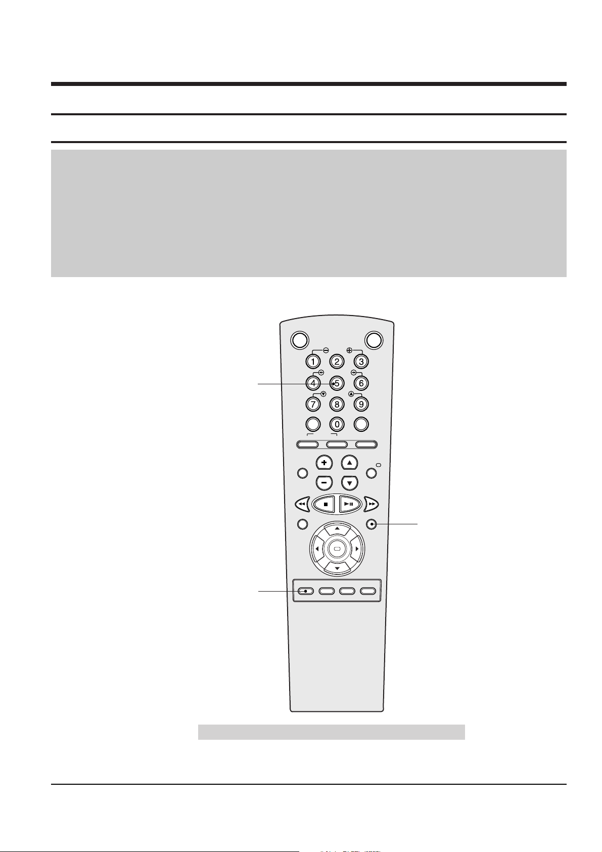
2-1-1 Location of adjustment button of remote control
Fig. 2-1
Remote Control for adjustment is not supplied as a Service Jig.
OK
VCR STANDBY/ON TV STANDBY/ON
SLOW
SHUTTLE
V-LOCK
CLR/RST F.ADV INDEX
TV VCR INPUT
REPEAT
VOL PROG/TRK
AUDIO
REC MENU
SPEED DUB TV/VCR TIMER
DISP./
SELECT
-/--
X-Point (Tracking Center) Adjustment
("5" Button)
Head Switching Adjustment
("SPEED" Button)
NVRAM Option Setting
("MENU" Button)
Page 2
2-2
Samsung Electronics
Alignment and Adjustment
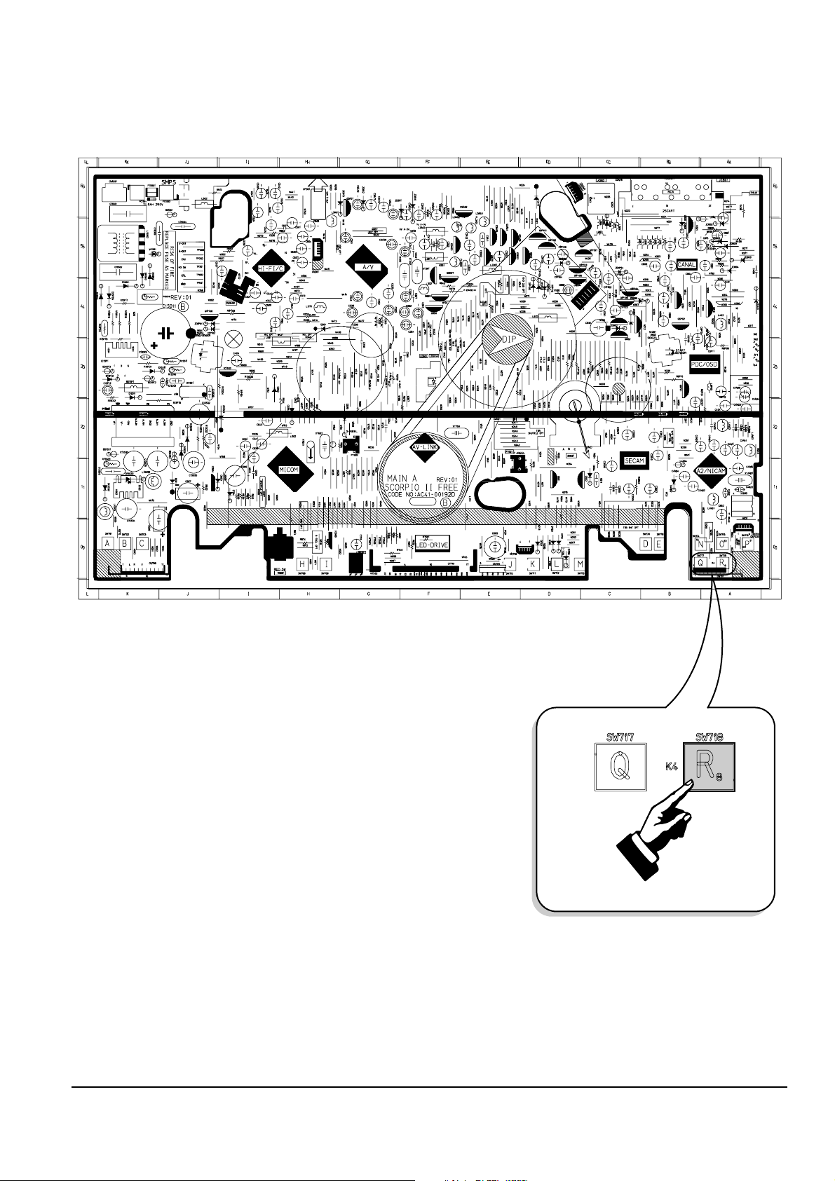
Fig. 2-2 Main PCB (Top View)
2-1-2 SW718 location for adjustment mode setting (Other Models)
PRESS
Page 3

Alignment and Adjustment
Samsung Electronics
2-3
Fig. 2-3 F/AV PCB (Top View)
PRESS
2-1-3 SW775 (TEST) location for adjustment mode setting (SV-750 Only)
Fig. 2-4 Function PCB (Top View)
PRESS
2-1-4 SW775 (TEST) location for adjustment mode setting (SV-659 Only)
Page 4

2-4
Samsung Electronics
Alignment and Adjustment
2-2 Mechanical Adjustment
Note : Refer to the Mechanical Manual “TS-10A (AC82-00023A)” for the adjustment and confirmation of
ass’y full deck.
2-2-1 The number and position of test point
Test point : TP301 (Envelope)
TP302 (Audio output)
TP602 (H’D S/W -Trigger)
Fig. 2-5 Location of Test point (Main PCB-Top View)
AUDIO OUTPUT
HEAD SWITCHING
ENVELOPE
2-2-2 ACE Head Position (X-Point) Adjustment
(See the 2-2-1(d) ACE Head Position (X-Point) Adjustment
on page 2-2 of the Mechanical Manual)
1) Playback the alignment tape (Color bar).
2) Press the “TEST” button on Main PCB/F/AV
PCB/Function PCB to set the adjustment mode.
(See Fig. 2-2, 2-3 and 2-5)
3) Press the “5” button of remote control then
adjustment is operated automatically. (See Fig. 2-1)
4) Connect the CH-1 probe to TP301 (Envelope) the
CH-2 probe to TP602 (H’D switching pulse) and
then trigger to CH-1.
5) Insert the (-) driver into the X-Point adjustment
hole and adjust it so that envelope waveform is
maximum.
6) Turn the Power off.
Page 5

Alignment and Adjustment
Samsung Electronics
2-5
<Table 2-1 NVRAM Option Number>
MODELS OPTION NUMBER
SVR-750 6, 9, 10, 12, 15, 20, 21, 22, 29, 32, 33, 34, 36, 39, 42, 44, 47, 50, 52, 54, 60, 61, 63, 65
SVR-659 2, 6, 9, 10, 12, 15, 19, 20, 21, 22, 29, 32, 33, 34, 36, 38, 42, 45, 47, 50, 54, 60, 61, 63, 65
SVR-653 6, 9, 10, 12, 15, 20, 24, 29, 32, 33, 34, 36, 38, 42, 44, 47, 49, 52, 54, 57, 60, 61, 63, 65
SVR-650 6, 9, 10, 12, 20, 32, 33, 34, 36, 38, 42, 44, 47, 49, 50, 51, 52, 57, 60, 61, 63, 65
SVR-557 6, 12, 20, 22, 24, 33, 34, 36, 37, 40, 44, 47, 49, 51, 52, 54, 57, 60, 61, 63, 65, 68
SVR-453 9, 10, 12, 15, 20, 24, 32, 33, 34, 36, 38, 42, 44, 47, 49, 52, 54, 57, 60, 61, 63, 65
SVR-450 9, 10, 12, 20, 32, 33, 34, 36, 38, 42, 44, 47, 49, 50, 51, 52, 54, 57, 60, 61, 63, 65
SVR-253 10, 12, 15, 20, 24, 32, 33, 34, 36, 37, 42, 44, 47, 49, 52, 54, 57, 60, 61, 63, 65, 71
SVR-250 10, 12, 20, 32, 33, 34, 36, 37, 42, 44, 47, 49, 50, 51, 52, 54, 57, 60, 61, 63, 65, 71
SVR-251W 10, 12, 20, 32, 33, 34, 36, 37, 42, 44, 47, 49, 51, 54, 57, 60, 61, 63, 65, 71
SVR-2501 10, 12, 20, 33, 34, 36, 37, 42, 44, 47, 52, 54, 57, 60, 61, 63, 65, 71
SVR-155 10, 12, 20, 33, 34, 36, 37, 40, 44, 47, 50, 51, 54, 57, 60, 61, 63, 65, 68, 71
SVR-151 10, 12, 20, 24, 33, 34, 36, 37, 40, 44, 47, 49, 51, 52, 54, 57, 60, 61, 63, 65, 68, 71
SVR-150 10, 12, 20, 33, 34, 36, 37, 40, 44, 47, 51, 54, 57, 60, 61, 63, 65, 68, 71
SVR-6503 6, 9, 10, 12, 20, 33, 34, 36, 38, 42, 44, 47, 49, 51, 54, 57, 60, 61, 63, 65
SVR-4503 9, 10, 12, 20, 33, 34, 36, 38, 42, 44, 47, 49, 51, 54, 57,60, 61, 63, 65
SVR-2503 12, 20, 33, 34, 36, 37, 42, 44, 47, 49, 50, 54, 57, 60, 61, 63, 65
SVR-1503 12, 20, 33, 34, 36, 37, 40, 44, 47, 49, 50, 54, 57, 60, 61, 63, 65, 68
2-3 Head Switching Point Adjustment
1) Playback the alignment tape.
2) Press the “TEST” button on Main PCB/F/AV PCB/Function PCB to set the adjustment mode.
(See Fig. 2-2, 2-3 and 2-4)
3) Press the “SPEED” button of remote control then adjustment is operated automatically. (See Fig. 2-1)
4) Turn the Power off.
2-4 NVRAM Option Setting
1) Press the “TEST” button on Main PCB/F/AV PCB/Function PCB to set the adjustment mode.
(See Fig. 2-2, 2-3 and 2-4)
2) Press the “MENU” button on the remote control about 5 seconds then option setting display is appeared.
(See Fig. 2-6)
3)
Select the option number (See Table 2-1) of corresponding model with “CURSOR” button on the remote control.
4) If selecting the option number is completed, press the “OK” button of remote control.
(If “OK” button is pressed, the selected number is changes reversed color. ; See Fig. 2-6)
5) Press the “MENU” button of remote control again to store the option number.
(“PLEASE WAIT” is displayed for a second as shown Fig. 2-7 and this setting is completed.)
6) Turn the Power off.
1) NVRAM Option is adjusted at production line basically.
2) In case Micom (IC601) and NVRAM (IC605 ; EEPROM) is replaced, be sure to set the corresponding option number of the repaired
model. (If the option is not set, the unit is not operated.)
01 02 03 04 05 06 07 08
09 10 11 12 13 14 15 16
17 18 19 20 21 22 23 24
25 26 27 28 29 30 31 32
33 34 35 36 37 38 39 40
41 42 43 44 45 46 47 48
49 50 51 52 53 54 55 56
57 58 59 60 61 62 63 64
65 66 67 68 69 70 71 72
CNG : OK SAVE : MENU
Fig. 2-6
01 02 03 04 05 06 07 08
09 10 11 12 13 14 15 16
17 18 19 20 21 22 23 24
25 26 27 28 29 30 31 32
33 34 35 36 37 38 39 40
41 42 43 44 45 46 47 48
49 50 51 52 53 54 55 56
57 58 59 60 61 62 63 64
65 66 67 68 69 70 71 72
PLEASE WAIT
Fig. 2-7
Page 6

2-6
Samsung Electronics
Alignment and Adjustment
MEMO
 Loading...