

Samsung SV-21, SV-41, SV-91 Schematic
VIDEO CASSETTE RECORDER
SV-D91
SV-D41
SV-D21
SERVICE
1. Precautions
2. Alignment and Adjustment
3. Exploded View and Parts List
4. Electrical Parts List
5. Schematic Diagrams
Manual
VIDEO CASSETTE RECORDER CONTENTS
For mechanical disassembly and adjustment, refer to the “Mechanical Manual” (DX-9R AC68-00001A).
SAMTRON
POWER
EJECT
POWER
REC
REW
F .F
STOP
PLAY
SERVICE MANUAL SV-D91/D41/D21
© Samsung Electronics Co., Ltd. JAN. 2000
Printed in Korea
AC68-00821A
IMPORTANT SERVICE GUIDE
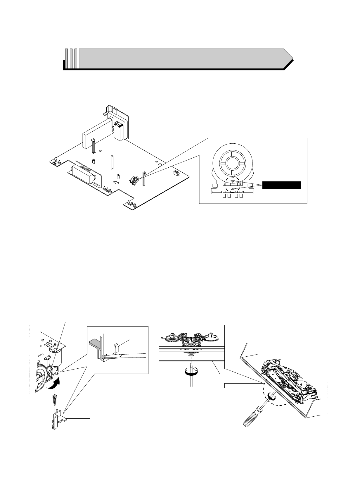
MODE SWITCH (PROGRAM SWITCH) ASSEMBLY POINT
1) When installing the ass’y full deck on the Main PCB, be sure to align the assembly point of mode switch.
ASSEMBLY POINT
Fig. 1
HOW TO EJECT THE CASSETTE TAPE
(If the unit does not operate on condition that tape is inserted into housing ass’y)
1) Remove the Holder Worm Œ and the gear worm ´. (See Fig. 2)
2) Turn the Gear Worm Wheel ˇ counterclockwise in the direction of arrow with screw driver. (See Fig. 2)
3) When Slider S, T are approached in the position of unloading, rotate holder Clutch counterclockwise after inserting screw driver in the
hole of frame’s bottom in order to wind the unwounded tape. (Refer to Fig. 3)
(If you rotate Gear Worm Wheel continuously when tape is in state of unwinding, you may cause a tape contamination by grease and
tape damage. Be sure to wind the unwounded tape in the state of set horizontally.)
4) Rotate Gear Worm Wheel ˇ counterclockwise using screw driver again up to the state of eject mode and then pick out the tape.
(Refer to Fig. 2)
Fig. 2 Fig. 3
ΠHOLDER WORM
´ GEAR WORM
SCREW DRIVER
ˇ GEAR WORM WHEEL
FRAME
Samsung Electronics 1-1
1. Precautions
1. Be sure that all of the built-in protective devices are
replaced. Restore any missing protective shields.
2. When reinstalling the chassis and its assemblies, be
sure to restore all pretective devices, including :
control knobs and compartment covers.
3. Make sure that there are no cabinet openings
through which people--particularly children
--might insert fingers and contact dangerous
voltages. Such openings include the spacing
between the picture tube and the cabinet mask,
excessively wide cabinet ventilation slots, and
improperly fitted back covers.
If the measured resistance is less than 1.0 megohm
or greater than 5.2 megohms, an abnormality exists
that must be corrected before the unit is returned
to the customer.
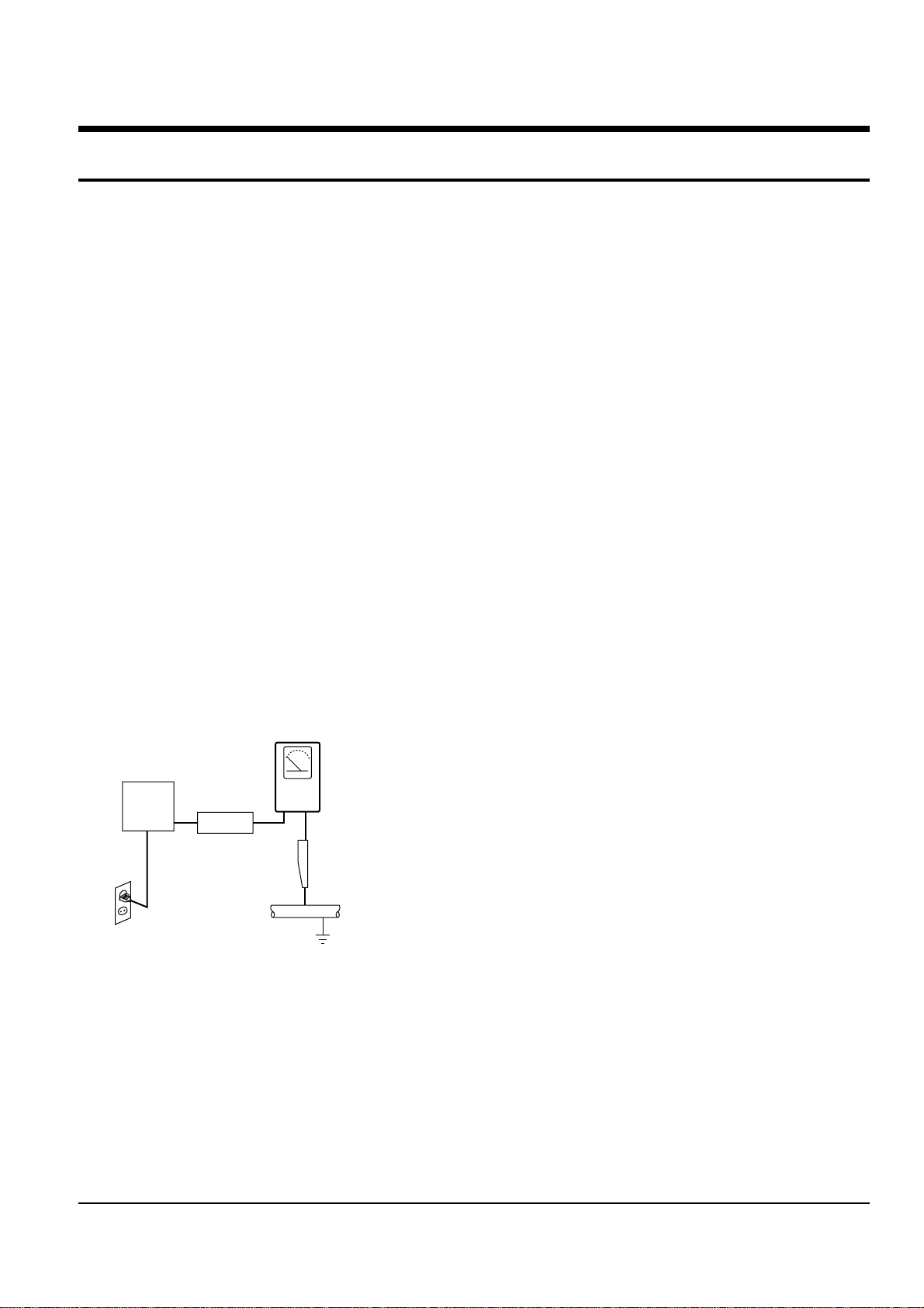
4. Leakage Current Hot Check (See Fig. 1-1) :
Warning : Do not use an isolation transformer
during this test. Use a leakage current tester or a
metering system that complies with American
National Standards Institute (ANSI C101.1,
Leakage Current for Appliances), and Underwriters
Laboratories (UL Publication UL1410, 59.7).
Fig. 1-1 AC Leakage Test
5. With the unit completely reassembled, plug the AC
line cord directly the power outlet. With the unit’s
AC switch first in the ON position and then OFF,
measure the current between a known erath
ground (metal water pipe, conduit, etc.) and all
exposed metal parts, including : antennas, handle
brackets, metal cabinets, screwheads and control
shafts. The current measured should not exceed
0.5 milliamp. Reverse the power-plug prongs in the
AC outlet and repeat the test.
6. Antenna Cold Check :
With the unit’s AC plug disconnected from the
AC source, connect an electrical jumper across the
two AC prongs. Connect one lead of the ohmmeter
to an AC prong.
Connect the other lead to the coaxial connector.
7. Some semiconductor (“solid state”) devices are
easily damaged by static electricity.
Such components are called Electrostatically
Sensitive Devices (ESDs); examples include
integrated circuits and some field-effect transistors.
The following techniques will reduce the
occurrence of component damage caused by static
electricity.
8. Immediately before handling any semiconductor
components or assemblies, drain the electrostatic
charge from your body by touching a known
earth ground. Alternatively, wear a discharging
Wrist-strap device. (Be sure to remove it prior to
applying power--this is an electric shock
precaution.)
9. Design Alteration Warning :
Never alter or add to the mechanical or electrical
design of this unit. Example : Do not add
auxiliary audio or video connectors.
Such alterations might create a safety hazard.
Also, any design changes or additions will void
the manufacturer’s warranty.
10. Never defeat any of the B+ voltage interlocks.
Do not apply AC power to the unit (or any of its
assemblies) unless all solid-state heat sinks are
correctly installed.
DEVICE
UNDER
TEST
(READING SHOULD
NOT BE ABOVE
0.5mA)
LEAKAGE
CURRENT
TESTER
EARTH
GROUND
TEST ALL
EXPOSED METER
SURFACES
ALSO TEST WITH
PLUG REVERSED
(USING AC ADAPTER
PLUG AS REQUIRED)
2-WIRE CORD

Precautions
1-2 Samsung Electronics
11. Always connect a test instrument’s ground lead to
the instrument chassis ground before connecting
the positive lead; always remove the instrument’s
ground lead last.
12. Observe the original lead dress, especially near
the following areas : Antenna wiring, sharp
edges, and especially the AC and high voltage
power supplies. Always inspect for pinched, outof-place, or frayed wiring. Do not change the
spacing between components and the printed
circuit board. Check the AC power cord for
damage. Make sure that leads and components
do not touch thermally hot parts.
13. Product Safety Notice :
Some electrical and mechanical parts have special
safety-related characteristics which might not be
obvious from visual inspection. These safety
features and the protection they give might be
lost if the replacement component differs from the
original--even if the replacement is rated for
higher voltage, wattage, etc.
Components that are critical for safety are
indicated in the circuit diagram by shading,
( or ).
Use replacement components that have the same
ratings, especially for flame resistance and
dielectric strength specifications. Areplacement
part that does not have the same safety
characteristics as the original might create shock,
fire or other hazards.
Samsung Electronics
2-1
2. Alignment and Adjustment
2-1 Reference
1) X-Point (Tracking center) adjustment, “Head switching adjustment” and “NVRAM option setting” can be adjusted with remote control.
2) When replacing the Micom (IC601) and NVRAM (IC605 ; EEPROM) be sure to adjust the “Head switching adjustment” and
“NVRAM option setting”.
3) When replacing the cylinder ass’y, be sure to adjust the “X-Point” and “Head switching adjustment”.
4) Among Samsung VCR remote control used for adjustment as a accessory, only the remote control that has figures buttons (0 ~ 9) is
available for all adjustment regardless of chassis.
5) How to adjustment.
- Press the “SW718 (TEST)” button on Main PCB to set the adjustment mode.
- If the corresponding adjustment button is pressed, the adjustment is performed automatically.
- If the adjustment is completed, be sure to turn the power off.
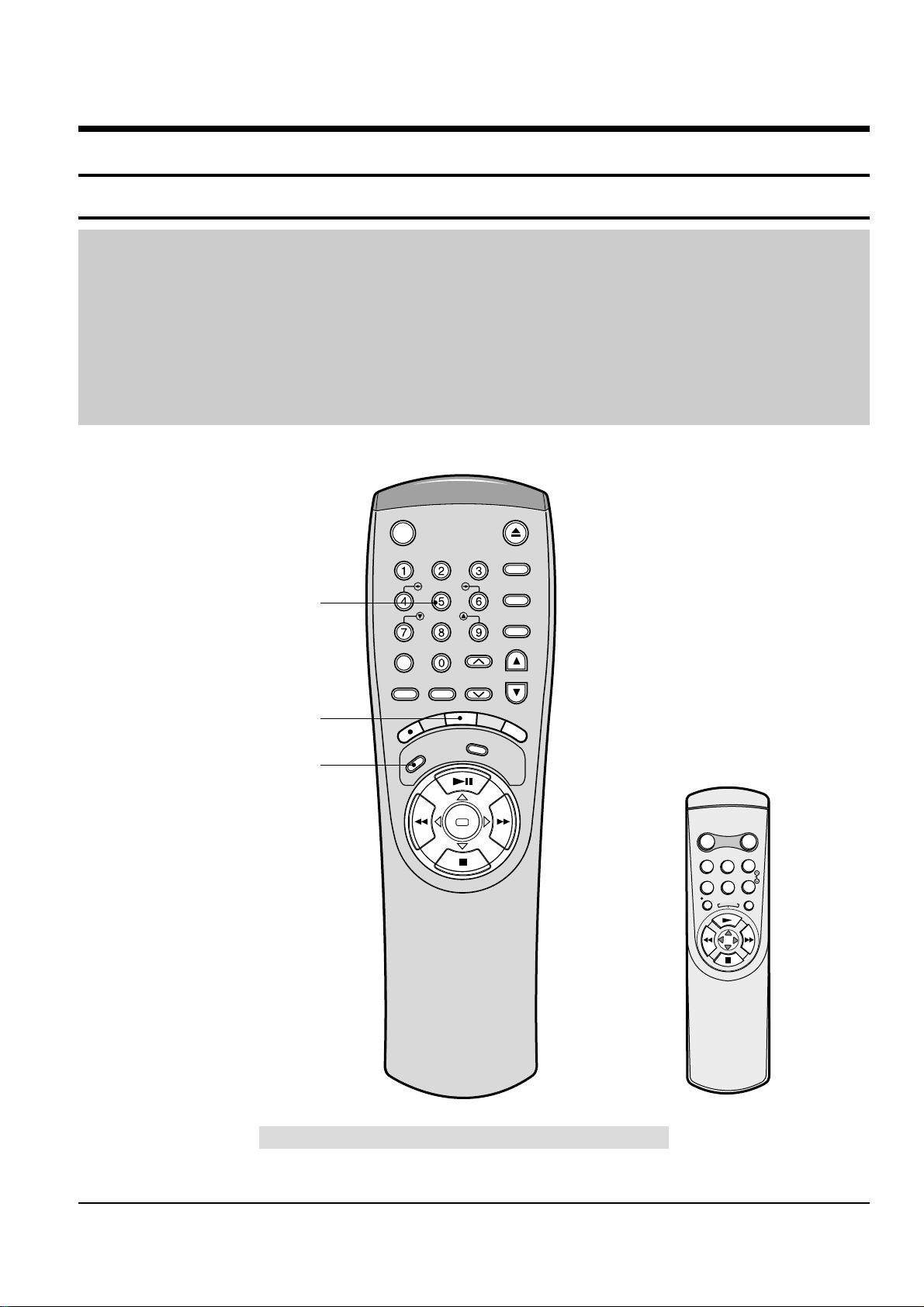
2-1-1 Location of adjustment button of remote control
Fig. 2-1
Q-PRO
IPC
DISPLAY
SHUTTLE
V-LOCK
CLR/RST F.ADV
INPUT INDEX
TRK PROG
R
E
C
M
E
N
U
A
U
D
I
O
S
P
E
E
D
T
V
/
V
C
R
REPEAT
OK
<This type of remote control can adjust.>
<This type of remote control can not adjust.>
Remote Control for adjustment is not supplied as a Service Jig.
R
E
P
E
A
T
POWER DISPLAY
CNT.RESET SPEED
IIP/S IPC
TRK
REC MENU
Head Switching Adjustment
("SPEED" Button)
NVRAM Option Setting
("MENU" Button)
X-Point (Tracking Center) Adjustment
("5" Button)
STANDBY/ON EJECT
2-2
Samsung Electronics
Alignment and Adjustment
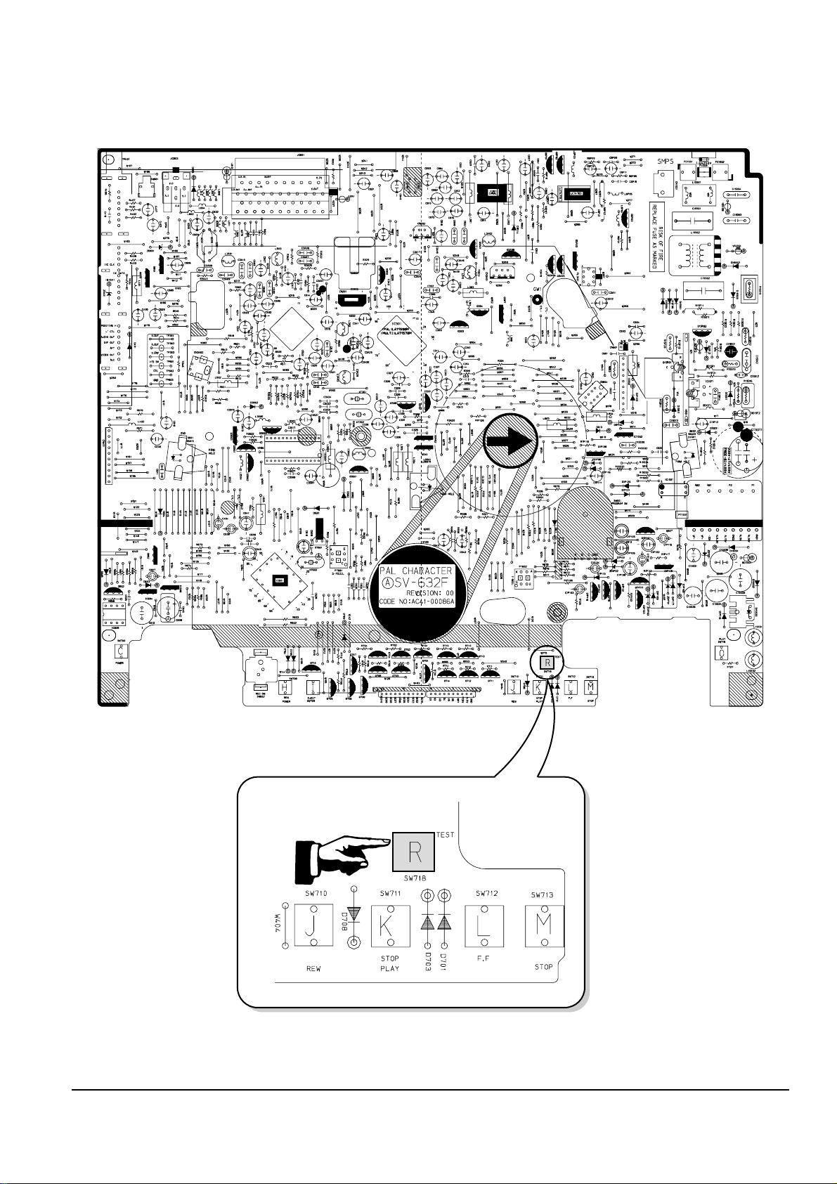
2-1-2 SW718 (TEST) location for adjustment mode setting
Fig. 2-2 Main PCB (Top View)
PRESS
Alignment and Adjustment
Samsung Electronics
2-3
2-2 Mechanical Adjustment
Note : Refer to the Mechanical Manual “DX-9R (AC68-00001A)” for the adjustment and confirmation of
ass’y full deck.
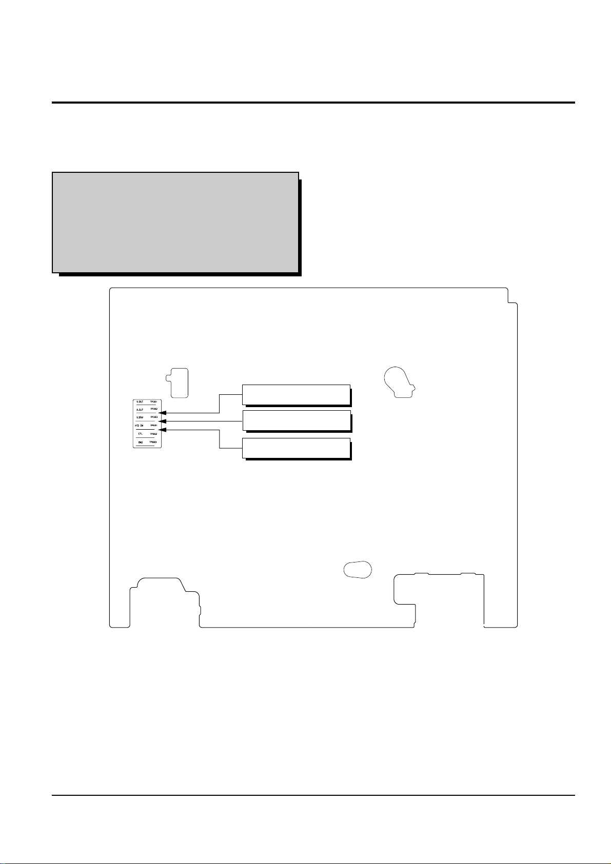
2-2-1 The number and position of test point
Test point : TP601 (H’D S/W -Trigger)
TP602 (Control pulse)
TP301 (Video output)
TP302 (Audio output)
TP303 (Envelope)
Fig. 2-3 Location of Test point (Main PCB-Top View)
AUDIO OUTPUT
HEAD SWITCHING
ENVELOPE
2-2-2 ACE Head Position (X-Point) Adjustment
(See the 2-2-1(d) ACE Head Position (X-Point) Adjustment
on page 2-2 of the Mechanical Manual)
1) Playback the alignment tape (Color bar).
2) Press the “SW718 (TEST)” button on Main PCB to
set the adjustment mode. (See Fig. 2-2)
3) Press the “5” button of remote control then
adjustment is operated automatically. (See Fig. 2-1)
4) Connect the CH-1 probe to TP303 (Envelope) the
CH-2 probe to TP601 (H’D switching pulse) and
then trigger to CH-1.
5) Insert the (-) driver into the X-Point adjustment
hole and adjust it so that envelope waveform is
maximum.
6) Turn the Power off.
2-4
Samsung Electronics
Alignment and Adjustment
2-3 Head Switching Point Adjustment
1) Playback the alignment tape.
2) Press the “SW718 (TEST)” button on Main PCB to set the adjustment mode. (See Fig. 2-2)
3) Press the “SPEED” button of remote control then adjustment is operated automatically. (See Fig. 2-1)
4) Turn the Power off.
2-4 NVRAM Option Setting
1) Press the “SW718 (TEST)” button on Main PCB to set the adjustment mode. (See Fig. 2-2)
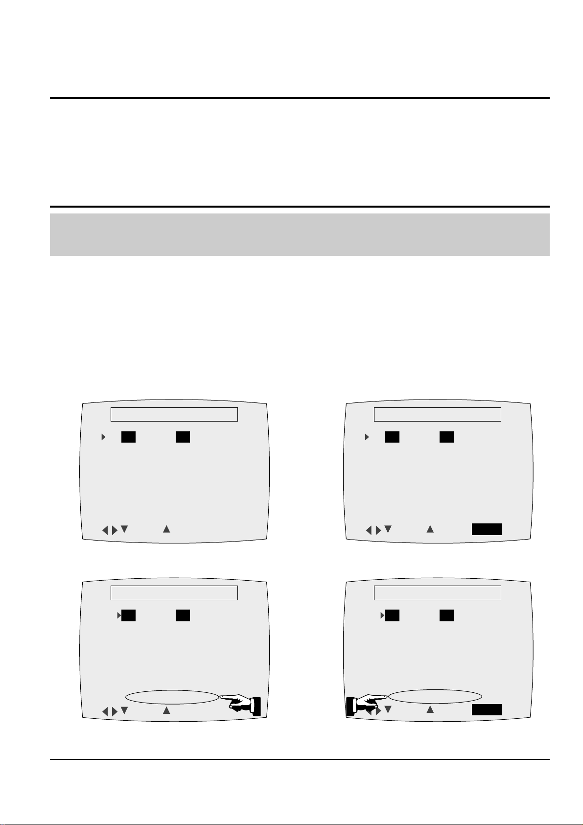
2) Press the “MENU” button on the remote control about 5 seconds then option setting display is appeared.
(See Fig. 2-4 and 2-5)
3) Select the option number (See Table 2-1 ; Page 2-5) of corresponding model with “FF” and “REW” button on
the remote control.
4) If selecting the option number is completed, press the “PLAY” button of remote control.
(If “PLAY” button is pressed, the selected number is changes reversed color. ; See Fig. 2-4 and 2-5)
5) Press the “OK (VCR)”, “MENU (VCP)” button of remote control again to store the option number.
(“PLEASE WAIT” is displayed for a second as shown Fig. 2-6, 2-7 and this setting is completed.)
6) Turn the Power off.
1) NVRAM Option is adjusted at production line basically.
2) In case Micom (IC601) and NVRAM (IC605 ; EEPROM) is replaced, be sure to set the corresponding option number of the repaired
model. (If the option is not set, the unit is not operated.)
01 02 03 04 05 06 07 08
09 10 11 12 13 14 15 16
17 18 19 20 21 22 23 24
25 26 27 28 29 30 31 32
33 34 35 36 37 38 39 40
41 42 43 44 45 46 47 48
49 50 51 52 53 54 55 56
**
OPTION DIODE
**
CNG : SAVE : OK
Fig. 2-4 (VCR)
01 02 03 04 05 06 07 08
09 10 11 12 13 14 15 16
17 18 19 20 21 22 23 24
25 26 27 28 29 30 31 32
33 34 35 36 37 38 39 40
41 42 43 44 45 46 47 48
49 50 51 52 53 54 55 56
**
OPTION DIODE
**
CNG : SAVE : MENU
Fig. 2-5 (VCP)
01 02 03 04 05 06 07 08
09 10 11 12 13 14 15 16
17 18 19 20 21 22 23 24
25 26 27 28 29 30 31 32
33 34 35 36 37 38 39 40
41 42 43 44 45 46 47 48
49 50 51 52 53 54 55 56
**
OPTION DIODE
**
CNG : SAVE : OK
PLEASE WAIT
Fig. 2-6 (VCR)
01 02 03 04 05 06 07 08
09 10 11 12 13 14 15 16
17 18 19 20 21 22 23 24
25 26 27 28 29 30 31 32
33 34 35 36 37 38 39 40
41 42 43 44 45 46 47 48
49 50 51 52 53 54 55 56
**
OPTION DIODE
**
CNG : SAVE : MENU
PLEASE WAIT
Fig. 2-7 (VCP)
Alignment and Adjustment
Samsung Electronics
2-5
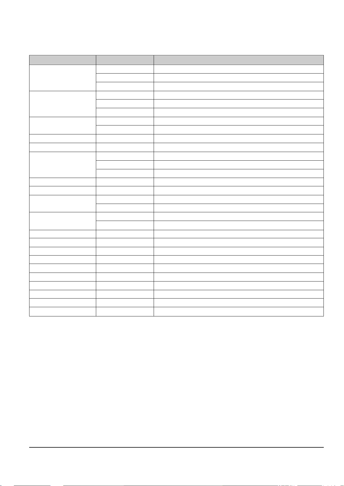
COUNTRY MODELS OPTION NUMBER
FRANCE SV-632FT/632FG 5, 8, 12, 13, 14, 15, 16, 18, 19, 22, 23, 26, 29, 35, 38, 50, 53, 54
SV-432FT/432FS/432FG/432FB
5, 8, 12, 16, 18, 19, 22, 23, 26, 29, 35, 38, 50, 53, 54
SV-232FT/232FS/232FG/232FB
5, 16, 18, 19, 22, 23, 26, 29, 35, 38, 50, 53, 54
U.K. SV-632B 6, 8, 10, 12, 13, 15, 16, 22, 23, 27, 35, 38, 50, 54
SV-234B 3, 8, 10, 16, 22, 27, 35, 38, 50, 54
SV-232B 8, 10, 16, 22, 27, 35, 38, 50, 54
GERMANY SV-632X
2, 5, 7, 8, 9, 10, 12, 13, 14, 16, 18, 22, 23, 24, 29, 32, 35, 38, 50, 53, 54
SV-232XB/232XS/232XG/232XM
2, 5, 7, 16, 18, 22, 23, 24, 29, 32, 35, 38, 50, 53, 54,
AUSTRIA SV-232X 2, 5, 7, 16, 18, 22, 23, 24, 32, 35, 38, 50, 53, 54
SWITZERLAND SV-232X 2, 5, 7, 16, 18, 22, 23, 24, 31, 32, 35, 38, 50, 53, 54
SPAIN SV-632X 5, 8, 9, 10, 12, 13, 14, 15, 16, 18, 22, 23, 31, 35, 38, 50, 53, 54
SV-234X 5, 7, 16, 18, 22, 23, 24, 31, 35, 38, 50, 53, 54
SV-232X 5, 16, 18, 22, 23, 31, 35, 38, 50, 53, 54
ITALY SV-232XS/232XB 5, 16, 18, 22, 23, 29, 31, 35, 38, 50, 53, 54
PORTUGAL SV-232X 5, 16, 18, 22, 23, 35, 38, 48, 50, 53, 54
NETHERLAND SV-632X
5, 8, 9, 10, 12, 13, 14, 15, 16, 18, 22, 23, 29, 30, 32, 35, 38, 50, 53, 54
SV-232X 16, 18, 22, 29, 30, 32, 35, 38, 50, 54
DENMARK SV-632X
5, 8, 9, 10, 12, 13, 14, 15, 16, 18, 22, 23, 29, 30, 35, 38, 50, 53, 54
SV-232X 16, 18, 22, 29, 30, 35, 38, 50, 54
SWEDEN SV-232X 16, 18, 22, 29, 30, 31, 35, 38, 50, 54
NORWAY SV-232X 16, 18, 22, 30, 31, 35, 38, 50, 54
GREECE SV-232X 16, 18, 22, 29, 31, 32, 35, 38, 50, 54
U.A.E. SV-232G
8, 11, 16, 17, 18, 20, 22, 25, 26, 30, 31, 32, 35, 38, 42, 48, 50, 54
SAUDI ARABIA SV-250G
8, 11, 16, 17, 18, 20, 22, 25, 26, 30, 31, 32, 35, 38, 42, 48, 50, 54
IRAN SV-250G 8, 11, 16, 17, 18, 20, 22, 25, 26, 29, 35, 38, 41, 42, 48, 50, 54
MALAYSIA SV-232G 8, 9, 10, 16, 17, 18, 20, 22, 25, 26, 29, 31, 32, 35, 38, 42, 50, 54
THAILAND
SV-D200B/D200M/D200G
8, 9, 10, 16, 17, 18, 22, 25, 26, 29, 31, 32, 35, 38, 42, 50, 54
SOUTH AFRICA SV-222I 8, 9, 11, 16, 17, 18, 22, 25, 26, 29, 31, 32, 35, 38, 42, 50, 54
AFRICA SV-D22K 9, 10, 11, 17, 18, 19, 22, 29, 31, 32, 34, 37, 39, 40, 42, 55
<Table 2-1>

2-6
Samsung Electronics
Alignment and Adjustment
MEMO

Samsung Electronics 3-1
3. Exploded View and Parts List
3-1 Cabinet Assembly - - - - - - - - - - - - - - - - - - - - - - - - - - - - - - - - - - - - - - - - -
3-2 Mechanical Parts (Top Side) - - - - - - - - - - - - - - - - - - - - - - - - - - - - - - - - -
3-3 Mechanical Parts (Bottom Side) - - - - - - - - - - - - - - - - - - - - - - - - - - - - - - -
Page
3-2
3-4
3-6
Exploded View and Parts List
3-2 Samsung Electronics
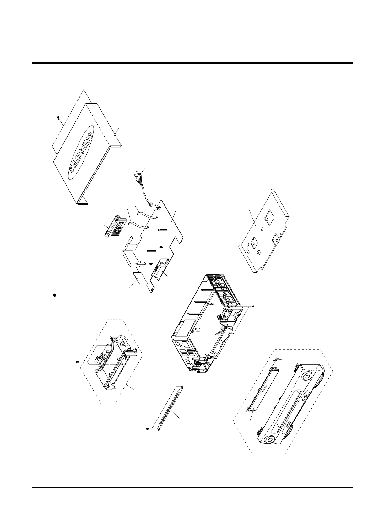
3-1 Cabinet Assembly
S.N.A. : Service Not Available
157
153
FULL DECK (S.N.A.)
TM401B
200
MAIN PCB (S.N.A.)
BRACKET-FRAME
(S.N.A.)
CN602A
CN3A1S
101
155
S601S
LD601S
S602S
LED PCB (S.N.A.)
102
157
1
1
21
22
A2/NICAM PCB-OPTION
(S.N.A.)
Exploded View and Parts List
Samsung Electronics 3-3
Loc. No Parts No. Description ; Specification Remark
1
Refer to table below
ASSY-PANEL FRONT;HIPS 94HB
21
Refer to table below
DOOR-CASSETTE
22 AC61-62032A SPRING-MASK;X-9,-,SUS,-,4.4,-,SV-C130
101
Refer to table below
CABINET-TOP;-,PCM(SECC),-0.525,320
102 AC63-00004A COVER-BOTTOM;-,SECC,-,PCM0.525,TM6524,-,
153 AC60-12126A SCREW-BH;-,BH,-,4*12,FE,FZY,-,-,155 AC60-12134A SCREW-TAP BH;-,BH,-,2-4X16,-,FE
157 AC60-10063A SCREW-TAPTITE;BH,+,-,M3,L12,ZPC3,SWRCH18
200 AC39-10019A POWER CORD COMMON
AC39-10022K POWER CORD U.K. ONLY
CN3A1S 3809-001111 CABLE-FLAT;30V,80C,130mm,7P,1.25mm,UL289
CN602A 3809-001049 CABLE-FLAT;30V,80C,100mm,5P,1.25mm,UL289
LD601S AC61-21009A HOLDER-LED;-,POM(M90-44),-,BLK,-,X-9
S601S AC61-21008A HOLDER-SENSOR;-,POM(M90-44),-,BLK,-,X-9
S602S AC61-21008A HOLDER-SENSOR;-,POM(M90-44),-,BLK,-,X-9
TM401B
Refer to table below
CONNECTOR BOARD-ASSY;HIPS94
COUNTRY MODELS
1 21 101 TM401B
FRANCE
SV-632FT AC97-00960A AC64-00375A AC64-00076E AC61-00021H
SV-632FG AC97-00862A AC64-00353A AC64-00076C AC61-00021H
SV-432FT AC97-00961A AC64-00375B AC64-00076E AC61-00021E
SV-432FS AC97-00881A AC64-00353E AC64-00076A AC61-00021E
SV-432FG AC97-00975A AC64-00375L AC64-00076C AC61-00021E
SV-432FB AC97-00880A AC64-00353D AC64-00076B AC61-00021E
SV-232FT AC97-00962A AC64-00375C AC64-00076E AC61-00021E
SV-232FS AC97-00978A AC64-00375P AC64-00076A AC61-00021E
SV-232FG AC97-00883A AC64-00353G AC64-00076C AC61-00021E
SV-232FB AC97-00882A AC64-00353F AC64-00076B AC61-00021E
U.K.
SV-632B AC97-00970A AC64-00353X AC64-00076C AC61-00021J
SV-234B AC97-00971A AC64-00353Y AC64-00076A AC61-00021G
SV-232B AC97-00863A AC64-00353T AC64-00076B AC61-00021G
GERMANY
SV-632X AC97-00972A AC64-00353Z AC64-00076A AC61-00021J
SV-232XB AC97-00973A AC64-00375D AC64-00076B AC61-00021F
SV-232XS AC97-00884A AC64-00353H AC64-00076A AC61-00021F
SV-232XG AC97-00885A AC64-00353J AC64-00076C AC61-00021F
SV-232XM AC97-00886A AC64-00353K AC64-00076A AC61-00021F
AUSTRIA
SV-232X AC97-00887A AC64-00353L AC64-00076A AC61-00021F
SWITZERLAND
SV-232X AC97-00887A AC64-00353L AC64-00076A AC61-00021F
SPAIN
SV-632X AC97-00974A AC64-00375E AC64-00076C AC61-00021J
SV-234X AC97-00889A AC64-00353M AC64-00076C AC61-00021F
SV-232X AC97-00888A AC64-00353U AC64-00076A AC61-00021F
PORTUGAL
SV-232X AC97-00890A AC64-00353N AC64-00076A AC61-00021F
ITALY
SV-232XS AC97-00891A AC64-00353P AC64-00076A AC61-00021F
SV-232XB AC97-00864A AC64-00353Q AC64-00076B AC61-00021F
NETHERLAND
SV-632X AC97-00866A AC64-00353B AC64-00076C AC61-00021J
SV-232X AC97-00892A AC64-00353R AC64-00076C AC61-00021G
DENMARK
SV-632X AC97-00866A AC64-00353B AC64-00076C AC61-00021J
SV-232X AC97-00892A AC64-00353S AC64-00076C AC61-00021G
SWEDEN
SV-232X AC97-00892A AC64-00353S AC64-00076C AC61-00021G
NORWAY
SV-232X AC97-00892A AC64-00353R AC64-00076C AC61-00021G
GREECE
SV-232X AC97-00892A AC64-00353R AC64-00076C AC61-00021G
U.A.E.
SV-232G AC97-00957A AC64-00375G AC64-00076A AC61-00021D
SAUDI ARABIA
SV-250G AC97-00977A AC64-00375N AC64-00076A AC61-00021D
IRAN
SV-250G AC97-00976A AC64-00121A AC64-00076A AC61-00021D
MALAYSIA
SV-232G AC97-00957A AC64-00375G AC64-00076A AC61-00021D
THAILAND
SV-D200B AC97-00867A AC64-00353C AC64-00076B AC61-00021D
SV-D200M AC97-00894A AC64-00353V AC64-00076A AC61-00021D
SV-D200G AC97-00895A AC64-00353W AC64-00076C AC61-00021D
SOUTH AFRICA
SV-222I AC97-00958A AC64-00375H AC64-00076A AC61-00021D
AFRICA
SV-D22K AC97-00959A AC64-00375J AC64-00076A AC61-00021D
Exploded View and Parts List
3-4 Samsung Electronics
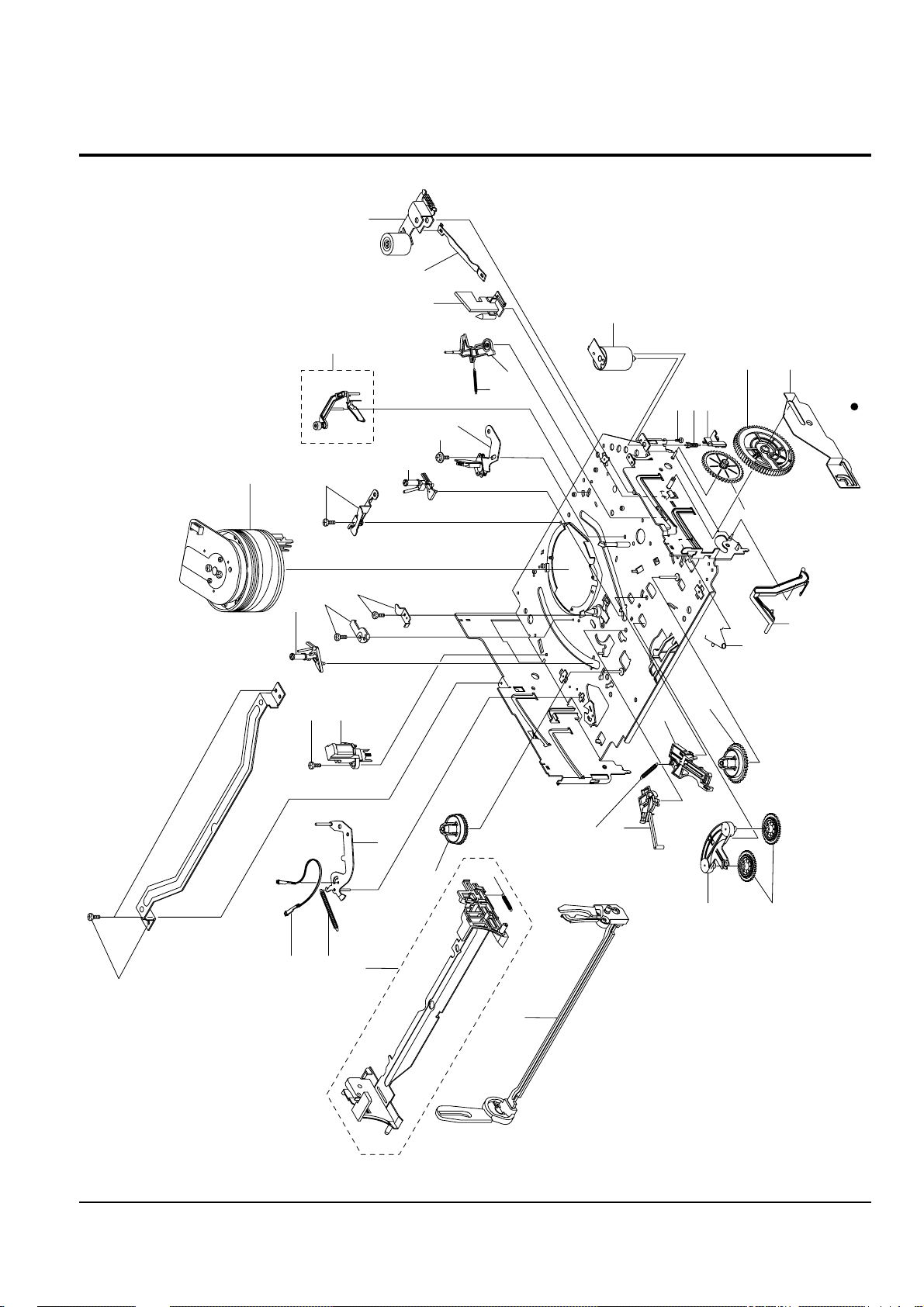
3-2 Mechanical Parts (Top Side)
G001
K250
K248
K110
K502
K350
K330
K182
K140
K490
K530
K240
G532
G420
G450
K546
G510
B410
B440
B444
B446
B448
B452
G527
G520
G480
G680
S.N.A.
S.N.A.
S.N.A.
S.N.A.
S.N.A.
G530
K340
B473
K188
G555
G546
S.N.A. : Service Not Available
S.N.A.
 Loading...