

Page 1
Alignment and Adjustments
Samsung Electronics 4-1
4. Alignment and Adjustments
4-1 When entering the service mode;
1. Turn on the TV, and then select “DYNAMIC” on the picture adjustment mode.
2. Turn off the TV(STAND-BY).
3. Enter the service mode by pressing the remote control keys in the following sequence:
Display -> Menu -> Mute -> Power ON
Note : If necessary, re-do steps 1~3.
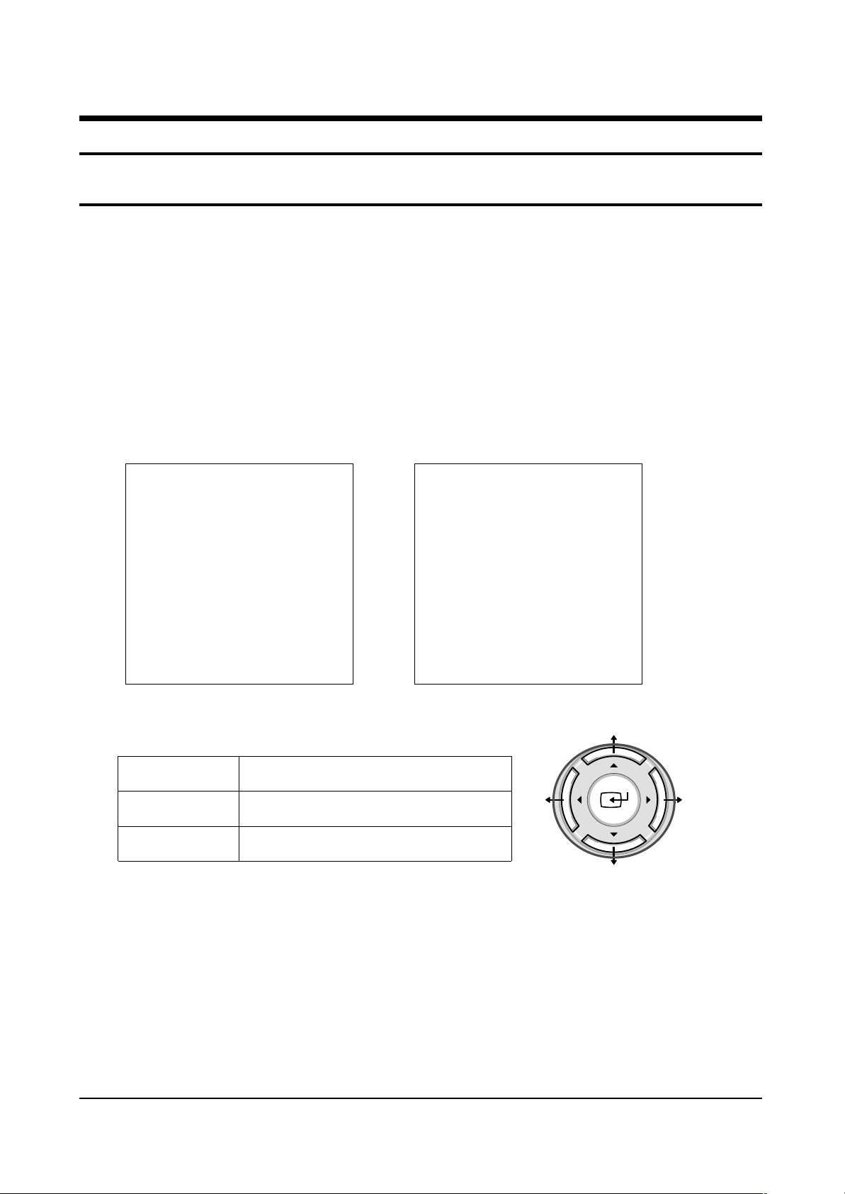
Initial display when the service mode is switched.
4-1-1 WHEN A RF SIGNAL IS RECEIVED
4-1-2 SERVICE MODE CONTROL KEYS
✍
PRECAUTIONS
1. When EEPROM IC (IC902) is replaced, first connect the power cord and wait for about 4~5 seconds.
2. After replacing EEPROM IC (IC902), enter the Service mode. Next, enter the standard data or the
previous EEPROM IC data before replacement. And then check and adjust any items related to
Geometric, Picture, Option.
DEFLECTION
VIDEO ADJUST 1
VIDEO ADJUST 2
VIDEO ADJUST 3
VIDEO ADJUST 4
OPTION (87h 05ch)
YC DELAY
RESET
SIM-814EW YY.MM.DD
MAIN MENU
UP / DOWN
RIGHT / LEFT
MENU DISPLAY
Select item by moving cursor
Decrease or increase the adjustment values
[Navigation Key]
CW MODEL
DEFLECTION
VIDEO ADJUST 1
VIDEO ADJUST 2
VIDEO ADJUST 3
VIDEO ADJUST 4
OPTION (D8 O4 2E)
YC DELAY
RESET
T_CADEC_010 YY.MM.DD
CS MODEL
Page 2
Alignment and Adjustments
4-2 Samsung Electronics
4-2 FACTORY MODE MENU
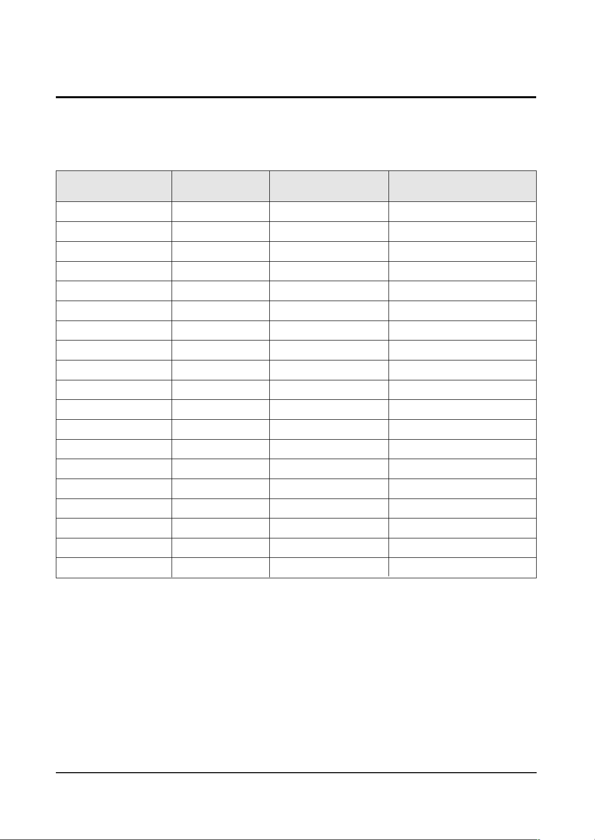
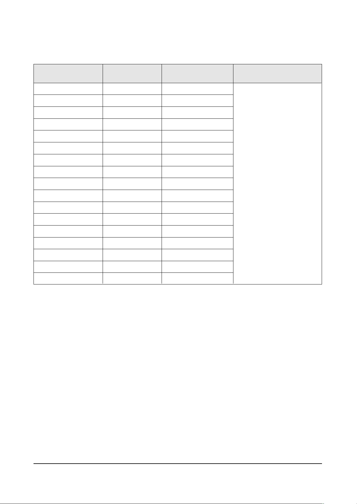
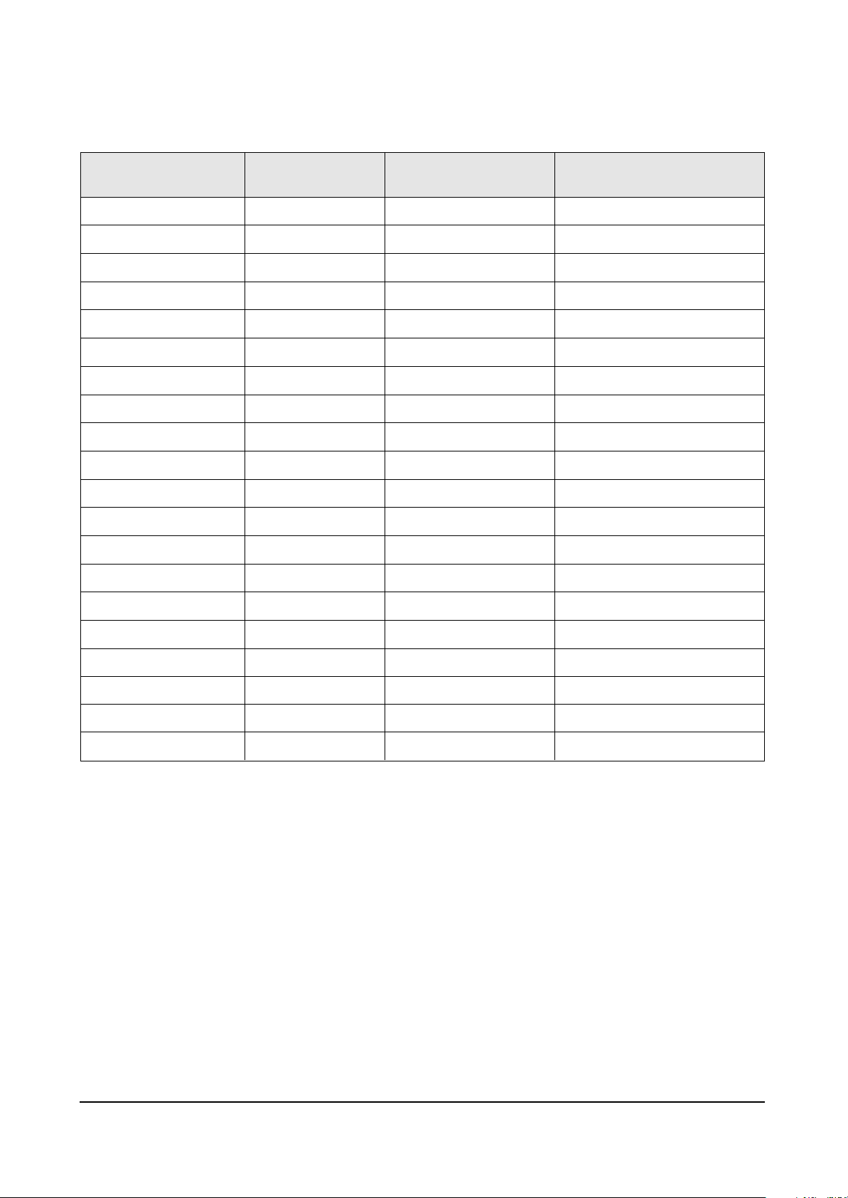
4-2-1(A) DEFLECTION
V Amp
V Shift
H EW
H Shift
V Linearity
Upper Linearity
Lower Linearity
V SC
H Parabolra
Upper Corner
Lower Corner
H Trapezium
Bow
Angle
V Position
Up UCG
Lo UCG
CXA Left Blk
CXA Right Blk
39
32
41
24
7
0
0
7
29
36
34
21
31
31
31
0
0
50
25
Item Range
Initial Data
0 ~ 63
0 ~ 63
0 ~ 63
0 ~ 63
0 ~ 15
0 ~ 15
0 ~ 15
0 ~ 15
0 ~ 63
0 ~ 63
0 ~ 63
0 ~ 63
0 ~ 63
0 ~ 63
0 ~ 63
0 ~ 3
0 ~ 3
0 ~ 63
0 ~ 63
Remark
Variable
FIX
Variable
FIX
FIX
FIX
FIX
FIX
FIX
FIX
FIX
FIX
FIX
FIX
FIX
FIX
FIX
FIX
FIX
4-2-1 CW MODEL(SIM-814EW)
Page 3
Alignment and Adjustments
Samsung Electronics 4-3
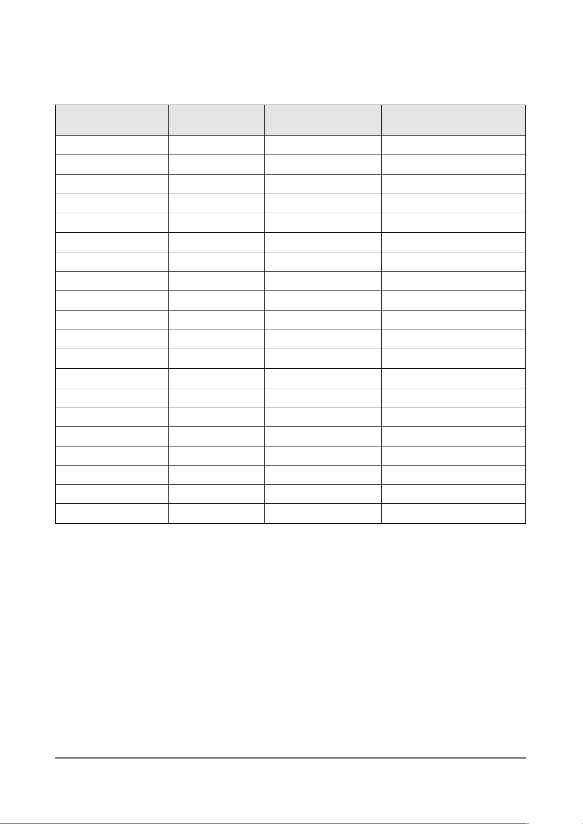
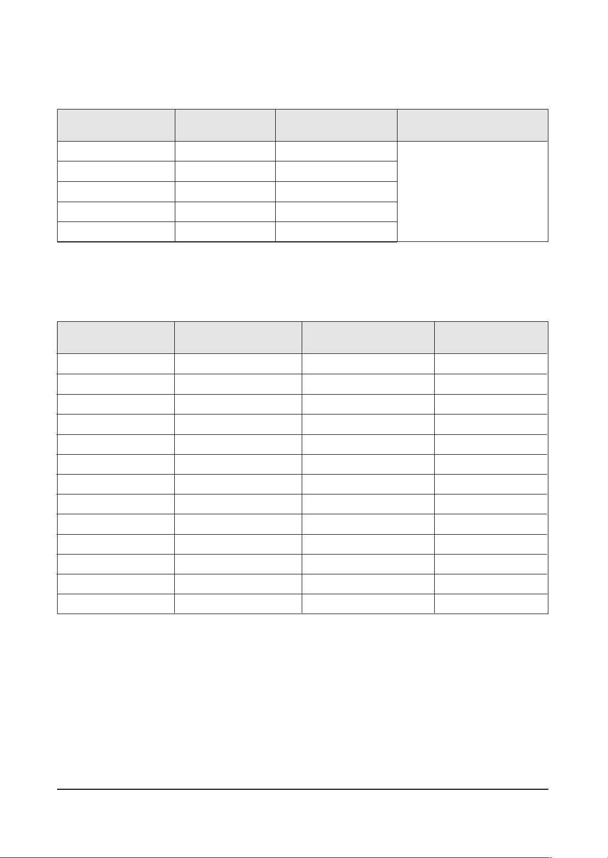
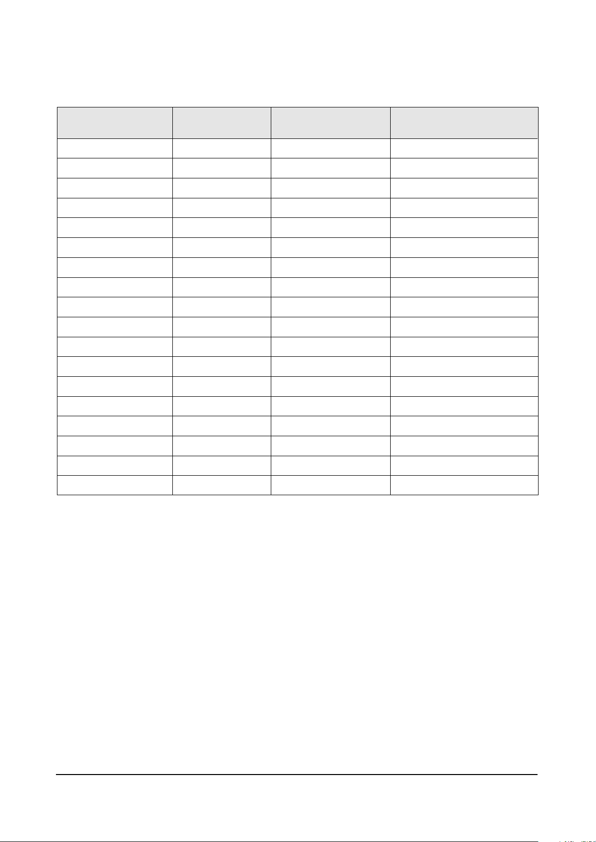
4-2-1(B) VIDEO ADJUST1
R Cutoff
G Cutoff
B Cutoff
Color On/Off
CB Offset
CR Offset
R Drive
G Drive
B Drive
Sub Bright
Sub Contrast
Sub Color
Sut Tint
CTI Level
COL Axis
LTI Level
VSU
Melody Volume
LIT Mode
System
25
25
25
1
31
31
25
25
25
15
8
3
31
1
1
1
2
4
1
1
Item Range
Initial Data
0 ~ 63
0 ~ 63
0 ~ 63
0 ~ 1
0 ~ 63
0 ~ 63
0 ~ 63
0 ~ 63
0 ~ 63
0 ~ 63
0 ~ 15
0 ~ 23
0 ~ 63
0 ~ 3
0 ~ 3
0 ~ 3
0 ~ 15
0 ~ 20
0 ~ 3
0 ~ 3
Remark
Variable
FIX
Variable
Variable
Variable
Variable
Variable
FIX
Variable
Variable
Variable
FIX
FIX
FIX
FIX
FIX
FIX
FIX
FIX
FIX
Page 4
Alignment and Adjustments
4-4 Samsung Electronics
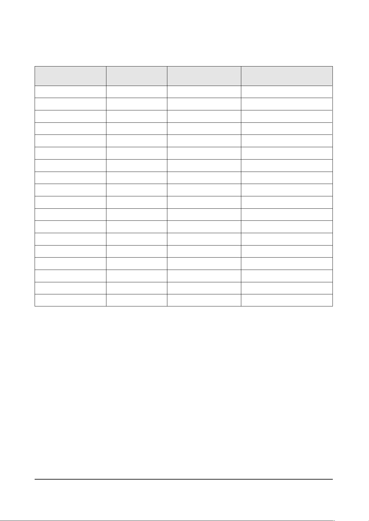
4-2-1(C) VIDEO ADJUST2
ABL Level
Gamma
DPIC Level
DC Trans
ABL TH
VM Level
VM Corint
VM f0
VM Limit
VM Delay
SHP CD
SHP f0
SHP f1 & P/O
AKB Time
BandPass 9407
HighPass 9407
S ABL
P ABL
3
1
2
1
15
1
0
1
1
1
0
1
11
13
24
40
0
15
Item Range
Initial Data
0 ~ 3
0 ~ 3
0 ~ 3
0 ~ 3
0 ~ 15
0 ~ 3
0 ~ 15
0 ~ 3
0 ~ 3
0 ~ 3
0 ~ 3
0 / 1
-
0 ~ 63
-
-
0 ~ 3
0 ~ 15
Remark
FIX
FIX
-
FIX
FIX
-
FIX
FIX
FIX
FIX
FIX
FIX
FIX
FIX
-
-
FIX
FIX
Page 5
Alignment and Adjustments
Samsung Electronics 4-5
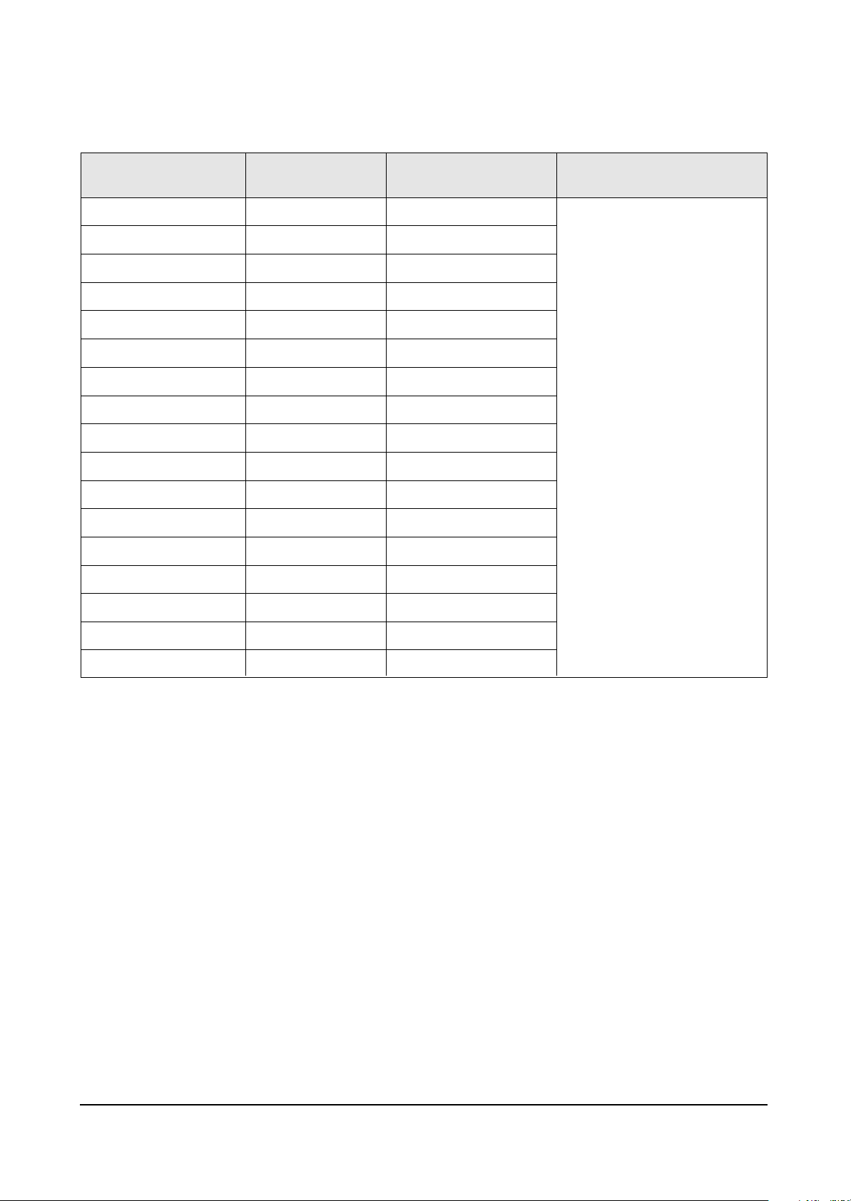
4-2-1(D) VIDEO ADJUST3
H Comp
V Comp
Pin Comp
AFC Comp
H-Sync Phase
NR Off Value
CG HAO
CG VAO
NR High Ref
NR Low Ref
NR High Value
NR Low Value
NR Hight Ref(S)
NR Low Ref(s)
NR High Value(S)
NR Low Value(S)
NR Read M/S
1
4
3
0
0
6
10
15
40
3
17
51
20
0
17
51
0 0
Item Range
Initial Data
0 ~ 15
0 ~ 15
0 ~ 7
0 ~ 7
0 / 1
0 ~ 9
0 ~ 20
0 ~ 20
0 ~127
0 ~127
0 ~255
0 ~255
0 ~127
0 ~127
0 ~255
0 ~255
0/27
Remark
FIX
Page 6
Alignment and Adjustments
4-6 Samsung Electronics
4-2-1(E) VIDEO ADJUST4
SECAM Color Main
SECAM Color Pip
Picture Limit
OSD Contrast
TTX Contrast
28
28
3
10
3
Item Range
Initial Data
0 ~255
0 ~255
0 ~ 3
0 ~ 15
0 ~ 15
Remark
FIX
4-2-1(F) OPTION
SYSTEM
SOUND
ASPECT
WIDE 4:3
X-RAY
AUTO FM
PIP
LNA
Letter Box
D/W PIP
AGC
Natural Zoom
HELP
CW
Virtual Dolby
WIDE
on
ON
ON
2-TUNER
On
ON
OFF
OFF
ON
ON
Item Setting Data
Appliance
CS/CW
A2-NICAM/Virtual Dolby
WIDE / 4:3
OFF / ON
OFF / ON
OFF / ON
OFF / 2-TUNER
OFF / ON
OFF / ON
OFF / ON
OFF / ON
OFF / ON
OFF / ON
Remark
Page 7
Alignment and Adjustments
Samsung Electronics 4-7
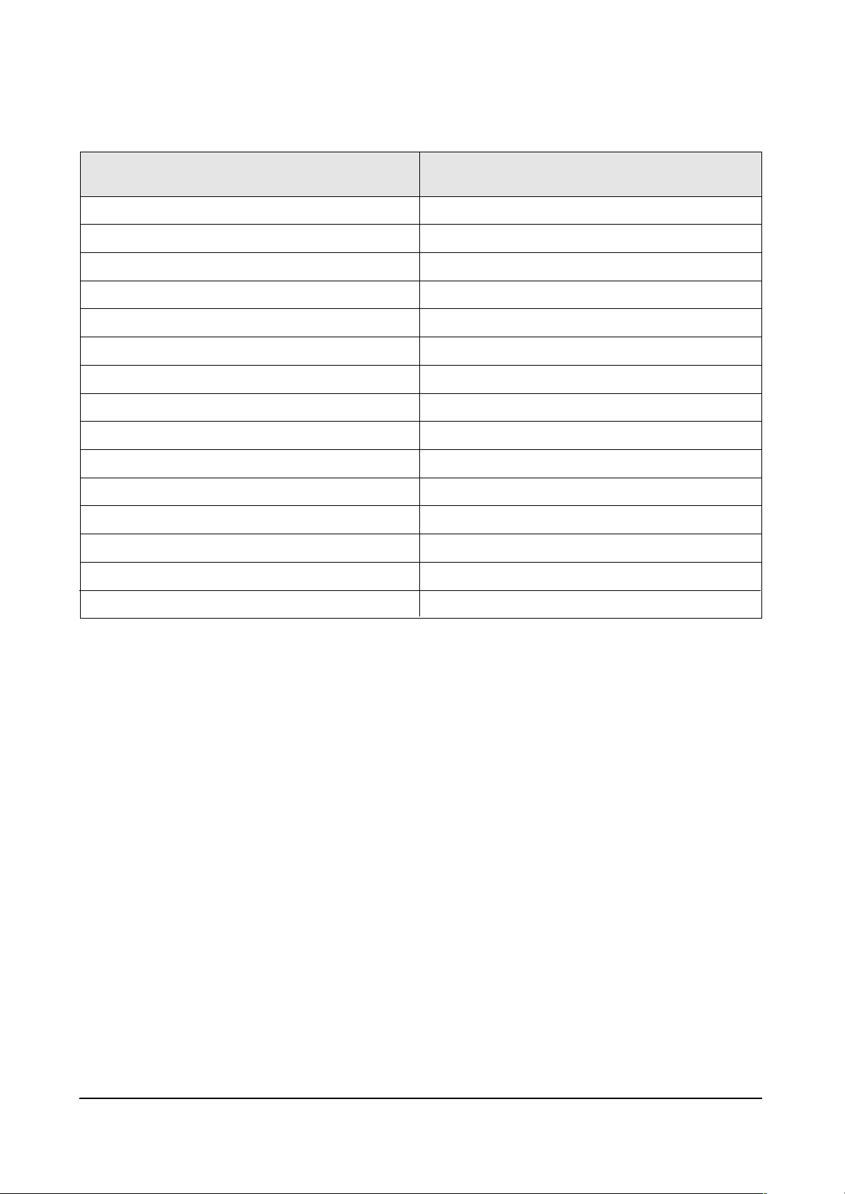
4-2-1(G) YC DELAY
P.YC(AV) Delay
S.YC(AV) Delay
N.YC(AV) Delay
P.BG.YC Dealy
P.DK.YC Delay
P.I.YC Delay
P.M.YC Delay
P.N.YC Delay
S.BG.YC Delay
S.DK.YC Delay
S.I.YC Delay
S.M.YC Delay
S.L.YC Delay
N.M.YC Delay
N4.43 YC Delay
Item Range
1
-5
1
1
-2
0
0
0
-7
-9
-9
-7
-10
3
-6
Page 8
Alignment and Adjustments
4-8 Samsung Electronics
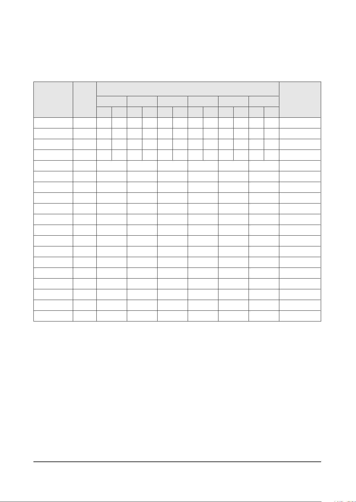
4-2-2(A) DEFLECTION
V Amp
V Shift
H EW
H Shift
V Linearity
Upper Linearity
Lower Linearity
V SC
H Parabolra
Upper Corner
Lower Corner
H Trapezium
Bow
Angle
V Position
Up UCG
Lo UCG
CXA Left Blk
CXA Right Blk
48
31
48
24
7
0
0
2
15
33
33
18
31
31
31
0
0
50
25
48
31
48
24
48
31
48
24
7
0
0
2
15
33
33
18
31
31
31
0
0
50
25
48
31
48
24
48
31
48
24
7
0
0
2
15
33
33
18
31
31
31
0
0
50
25
48
31
48
24
48
31
48
24
7
0
0
2
15
33
33
18
31
31
31
0
0
50
25
48
31
48
24
48
31
48
24
7
0
0
2
15
33
33
18
31
31
31
0
0
50
25
48
31
48
24
48
31
48
24
7
0
0
2
15
33
33
18
31
31
31
0
0
50
25
48
31
48
24
Item Range
Initial Data
0 ~ 63
0 ~ 63
0 ~ 63
0 ~ 63
0 ~ 15
0 ~ 15
0 ~ 15
0 ~ 15
0 ~ 63
0 ~ 63
0 ~ 63
0 ~ 63
0 ~ 63
0 ~ 63
0 ~ 63
0 ~ 3
0 ~ 3
0 ~ 63
0 ~ 63
Remark
Variable
FIX
Variable
FIX
FIX
FIX
FIX
FIX
FIX
FIX
FIX
FIX
FIX
FIX
FIX
FIX
FIX
FIX
FIX
4-2-2 CS MODEL(T_CADEC_010)
42W5
NTSC PAL
47W1
NTSC PAL
43T6/43T7
NTSC PAL
48T6
NTSC PAL
54T6
NTSC PAL
62T6
NTSC PAL
Page 9
Alignment and Adjustments
Samsung Electronics 4-9
4-2-2(B) VIDEO ADJUST1
R Cutoff
G Cutoff
B Cutoff
Color On/Off
CB Offset
CR Offset
R Drive
G Drive
B Drive
Sub Bright
Sub Contrast
Sub Color
Sut Tint
CTI Level
COL Axis
LTI Level
VSU
Melody Volume
LIT Mode
System
25
25
25
1
31
31
25
25
25
15
8
3
31
1
2
1
2
4
1
1
Item Range
Initial Data
0 ~ 63
0 ~ 63
0 ~ 63
0 ~ 1
0 ~ 63
0 ~ 63
0 ~ 63
0 ~ 63
0 ~ 63
0 ~ 63
0 ~ 15
0 ~ 23
0 ~ 63
0 ~ 3
0 ~ 3
0 ~ 3
0 ~ 15
0 ~ 20
0 ~ 3
0 ~ 3
Remark
Variable
Variable
Variable
Variable
Variable
Variable
Variable
Variable
Variable
Variable
Variable
FIX
FIX
FIX
FIX
FIX
FIX
FIX
FIX
FIX
Page 10
Alignment and Adjustments
4-10 Samsung Electronics
4-2-2(C) VIDEO ADJUST2
ABL Level
Gamma
DPIC Level
DC Trans
ABL TH
VM Level
VM Corint
VM f0
VM Limit
VM Delay
SHP CD
SHP f0
SHP f1 & P/O
AKB Time
BandPass 9407
HighPass 9407
S ABL
P ABL
3
1
2
1
15
1
0
1
1
1
0
1
11
13
24
40
0
15
Item Range
Initial Data
0 ~ 3
0 ~ 3
0 ~ 3
0 ~ 3
0 ~ 15
0 ~ 3
0 ~ 15
0 ~ 3
0 ~ 3
0 ~ 3
0 ~ 3
0 / 1
-
0 ~ 63
-
-
0 ~ 3
0 ~ 15
Remark
FIX
FIX
FIX
FIX
FIX
FIX
FIX
FIX
FIX
FIX
FIX
FIX
FIX
FIX
FIX
FIX
FIX
FIX
Page 11
Alignment and Adjustments
Samsung Electronics 4-11
4-2-2(D) VIDEO ADJUST3
H Comp
V Comp
Pin Comp
AFC Comp
H-Sync Phase
NR Off Value
CG HAO
CG VAO
NR High Ref
NR Low Ref
NR High Value
NR Low Value
NR Hight Ref(S)
NR Low Ref(s)
NR High Value(S)
NR Low Value(S)
NR Read M/S
1
4
3
0
0
6
10
15
40
3
17
51
20
0
17
51
0 0
Item Range
Initial Data
0 ~ 15
0 ~ 15
0 ~ 7
0 ~ 7
0 / 1
-
0 ~ 20
0 ~ 20
0 ~127
0 ~127
-
-
0 ~127
0 ~127
-
-
-
Remark
FIX
Page 12

Alignment and Adjustments
4-12 Samsung Electronics
4-2-1(E) VIDEO ADJUST4
SECAM Color Main
SECAM Color Pip
Picture Limit
OSD Contrast
TTX Contrast
28
28
3
10
3
Item Range
Initial Data
0 ~255
0 ~255
0 ~ 3
0 ~ 15
0 ~ 15
Remark
FIX
4-2-1(F) OPTION
LANGUAGE
SOUNG
CRT
CHANNEL
X-LAY
TTX
AUTO FM
PIP
MULTI PIP
LNA
HIGH DEV
SCART
LETTER BOX
DW PIP
LIST PRIOR
TTX LANG
AGC
AV MEMORY
AUSTRALIA
ONLY ENG
ENG+THAI(Thailand)
Virtual Dolby
4:3(Option)
100-channel
ON
ON
ON
2-TUNER
ON
ON
OFF
RCA+1SCART+DVD
ON
OFF
OFF
0N(AUSTRALIA)
WEST EUROPE
OFF
OFF
OFF
Item Setting Data
Appliance
(Southeast Asia)
ENG+CHINA
Virtual Dolby
4:3(Option)
200-channle
ON
OFF
ON
2-TUNER
ON
ON
OFF
RCA+DVD
ON
OFF
OFF
WEST EUROPE
OFF
OFF
OFF
Appliance
(CHINA)
ENG+MIDDLE
Virtual Dolby
4:3(Option)
250-channle
ON
ON
ON
2-TUNER
ON
ON
OFF
RCA+1SCART+DVD
ON
OFF
OFF
ARABIC
OFF
OFF
OFF
Appliance
(Middle East)
ENG+THAI / ENG+CHINA
ENG+MIDDLE / ONLY ENG
A2-NICAM/Virtual Dolby
WIDE / 4:3
100-channel / 200-channel
/250-chanel
OFF / ON
OFF / ON
OFF / ON
OFF / 2-TUNER
OFF / ON
OFF / ON
OFF / ON
RCA+1SCART+DVD / RCA+DVD
OFF / ON
OFF / ON
OFF / ON
WEST EUROPE / EAST EUROPE
RUSSIAN / GREEK-TURKEY
ARABIC / FARSI / AREB-HEBREW
OFF / ON
OFF / ON
OFF / ON
Page 13

Alignment and Adjustments
Samsung Electronics 4-13
4-2-2(G) YC DELAY
P.YC(AV) Delay
S.YC(AV) Delay
N.YC(AV) Delay
P.BG.YC Dealy
P.DK.YC Delay
P.I.YC Delay
P.M.YC Delay
P.N.YC Delay
S.BG.YC Delay
S.DK.YC Delay
S.I.YC Delay
S.M.YC Delay
S.L.YC Delay
N.M.YC Delay
Item Range
1
-5
1
1
-2
0
0
0
-7
-9
-9
-7
-10
3
Page 14

Alignment and Adjustments
4-14 Samsung Electronics
4-3 Screen Change (When Adjusting I2C Bus Geometric Items)
1 V AMP
2 V SHIFT
3 H EW
6 V - S - CORRECTION
7
H Parabolra
8
H Trapezium
4 H SHIFT
5 V LINEARITY
9 BOW
10 ANGLE
Page 15

Alignment and Adjustments
Samsung Electronics 4-15
4-4 Other Adjustments
4-4-1 Screen Adjustment
1. Warm up the TV for at least 30 minutes.
2. Select the “DYNAMIC” Video mode.
3. Trun to the Video Mode(No Signal) using a
remote-control.
4. Connect an oscilloscope to RK, GK, BK.
5. Adjust the VR (VR501, VR531, VR561) screen
so that RK, GK, BK pulse is 20Vp-p each.
(Turn the R,G,B VR screen fully
counterclockwise in the area of each flyback
line.)
4-4-2 White Balance Adjustment
1. Select the “DYNAMIC” video mode.
2. Input 100% white pattern.
3. In the stand-by mode, press the remote-control
keys in the following sequence:
Displsy → Menu → Mute → Power ON
4. Warm up the TV for at least 30 minutes.
5. Input a 10-step signal.
6. R-cut off, B-cut off, and G-cut off by pressing
the Volume +/- keys.
7. Adjust the low light with viewing the dark
side of the screen.
8. Select R-drive, G-drive and B-drive by
pressing the Volume +/- keys.
9. Adjust the high light with viewing the light
side of the screen.
10. If necessary, redo adjustments 6~9.
11. Press the Menu key to exit.
4-6-3 Sub-Brightness Adjustment
1. Input a sub-brightness adjustment signal.
(TOSHIBA PATTERN)
2. In the stand-by mode, press the remote-control
keys in the following sequence :
Displsy → Menu → Mute → Power ON
3. Select Sub-Bright by pressing the Volume +/keys.
4. Adjust so that the 63 step on the right side of
the screen is not seen (Use the Volume +/keys).
5. Press the Menu key to exit.
4-4-4 High Voltage (30KV) Check
PRECAUTION
1. Input a lion head pattern.
2. Select “DYNAMIC” video mode.
3. Warm up the TV for at least 10 minutes.
4. Use a digital multimeter.
ADJUSTMENT
1. Connect the (+) terminal of the digital
multimeter to Q471 and the (-) terminal to
Q401 (located on the deflection board).
2. Adjust RR471S (located on the sub board) so
that the digital meter indicates
DC290V ± 0.1V.
4-4-5 F.S. (Fail Safe) Circuit Check
(GT430,GT431)
Note : The F.S. Circuit check must be performed
after servicing.
1. Turn on the TV.
2. Select the “DYNAMIC” video mode.
3. Short F/S Test point (located on the SUB PCB).
Then, both sound and picture disappear.
(Note: Even if the shorted terminals are
removed, both sound and
picture do not appear. This proves the F.S.
circuit is working. )
4. To restore both sound and picture, turn off the
TV and reset it after about 30 seconds.
Page 16

Alignment and Adjustments
4-16 Samsung Electronics
4-4-6 Static Focus Adjustment
PRECAUTION
1. Select the “DYNAMIC” video mode.
2. Input a crosshatch pattern.
3. Cover the lenses that are not being adjusted.
4. Connect a convergence jig and read data.
5. Adjust the lens for best focus.
(See Fig, 4-1)
STATIC FOCUS (CONTINUED)
Vary the focus pack VR (Red, Blue) on the
front cabinet. Adjust the TV for best possible
focus around the center of the crosshatch
pattern, without losing overall screen balance.
Figure Crosshatch Pattern
Examine these points together.
4-4-7 Lens Focus Adjustment
PRECAUTIONS
1. Do this adjustment after the static focus
adjustment and the tilt adjustment.
2. Select the “DYNAMIC” video mode.
(Contrast:100, Brightness:50)
3. Input a crosshatch pattern.
ADJUSTMENT
1. Loosen the lens screws.
2. Cover the two lenses that are not being
adjusted.
3. Adjust the lens, observing the color aberration
vertically and horizontally within 3 blocks of
the center of the crosshatch pattern.
4. When the lens is turned clockwise, the color
aberration will change as follows:
Lens Color
Aberration Change
R Orange - Crimson
G Blue - Red
B Purple - Green
5. Green lens adjustment:
Set the lens at the point where Blue just
changes to Red. If the color aberration is
irregular throughout the picture screen, adjust
the lens to show Red color aberration
(approximately 1~3 mm area) within a 3-block
grid around the horizontal center-line. If the
color aberration is irregular, adjust the lens as
shown in the diagram below. (Accurate
alignment of Green is important for overall
color quality.)
6. Red lens adjustment
Set the Red lens at the point where Orange
becomes Crimson.
7. Blue lens adjustment
Set the Blue lens at the point where Purple
becomes Green.
P
L1
L2
RED ABERRATION
BLUE ABERRATION
L1, L2 < P
_
Fig. 4-1 Crosshatch Pattern.
Examine these points together
Fig. 4-2 Color Aberration
Page 17

Alignment and Adjustments
Samsung Electronics 4-17
1. Select the “DYNAMIC” video mode.
2. Warm up the set at least for 10 minutes.
3. Enter the Convergence mode by pressing the remote control buttons in the following sequence :
4. Set the Beam Alignment Adjustment CY to Zero magnetic field area.
5. Check the squarewave at the point where the focus is misaligned.
6. Press the button on the remote control during 3~5 sec and vibrating dot-pattern appears.
7. Adjust the Focus-pack VR for defocusing.
8. Mute the other patterns (R/B) other than G-PATTERN.
(Use / buttons on the remote control.)
9. Adjust the 2, 4 polarities of VM-COIL as shown in figure below.
10. Adjust the G-Focus until any light around the core disappears.
11. Adjust G-Focus so that the surrounding flash can disappear from the spot.
12. After G-Focus adjustments are complete, adjust R-Focus as above procedures.
13. The B-CRT adjustments can be omitted because the variance of beam focus is small.
(Only Vm-coil is mounted.)
14. Adjust the Focus-pack VR for fine focusing.
15. Press the button on the remote control, and the mode changes to the Convergence Adjustment
mode.
16. Press the button on the remote control to return to normal viewing.
4-5 Beam alignment Adjustments
Mute
(Creation of CPM Zero Magnet)
(Creation of the 2-pole/4-pole zero magnets)
TV
G-FOCUS
(Varying G-Focus Pack)
G-FOCUS
(When VM 2-Pole Adjustment is completed)
CORE
CORE
Varying the 2-pole of VM
Varying the 4-pole of VM
(Positioning the Core in the Center)
(Adjust until the light around
the core becomes a circle)
S.STD
Page 18

Alignment and Adjustments
4-18 Samsung Electronics
4-6 SCREEN-JIG
4-6-1 42W5
4-6-2 47W3
42W5 Screen Size : X 932, Y 524 (X:764 = 22 x 2 + 60 x 12, Y:262 = 17 x 2 + 38 x 6)-PAL MODE
26.84mm 73.19mm
34.00mm
76.00mm
34.00mm
26.84mm
47W3 Screen Size : X 1045, Y 588 (X:764 = 22 x 2 + 60 x 12, Y:262 = 17 x 2 + 38 x 6)-PAL MODE
30.09mm 82.07mm
3 8.1 5 mm
85.28mm
38.15mm
30.09mm
Page 19

Alignment and Adjustments
Samsung Electronics 4-19
4-6-3 55W3
4-6-4 65W3
55W3 Screen Size : X 1225, Y 686 (X:764 = 22 x 2 + 60 x 12, Y:262 = 17 x 2 + 38 x 6)-PAL MODE
35.27mm 96.20mm
44.51mm
99.50mm
44.51mm
35.27mm
65W3 Screen Size : X 1442, Y 838 (X:764 = 22 x 2 + 60 x 12, Y:262 = 17 x 2 + 38 x 6)-PAL MODE
41.52mm
5 4.3 7 mm
211.54mm
54.37mm
131
.25m m
41.52mm
Page 20

Alignment and Adjustments
4-20 Samsung Electronics
4-6-5 43T6/43T7
4-6-6 48T6
43T6 Screen Size : X 885, Y 666 (X:764 = 22 x 2 + 60 x 12, Y:262 = 17 x 2 + 38 x 6)-PAL MODE
43.21mm
96.60mm
43.21mm
25.48mm 69.50mm
25.48mm
48T6 Screen Size : X 973.4 Y 738.4 (X:764 = 22 x 2 + 60 x 12, Y:262 = 17 x 2 + 38 x 6)-PAL MODE
28.03mm 28.03mm
4 7.9 1 mm
071.10mm
4 7.9 1 mm
6.45mm
7
Page 21

Alignment and Adjustments
Samsung Electronics 4-21
4-6-5 54T6
4-6-6 62T6
54T6 Screen Size : X 1099 Y 823 (X:764 = 22 x 2 + 60 x 12, Y:262 = 17 x 2 + 38 x 6)-PAL MODE
31 8.65mm 31.65mm6.31mm
5 3.4 0 mm
191.37mm
5 3.4 0 mm
62T6 Screen Size : X 1259.4, Y 948 (X:764 = 22 x 2 + 60 x 12, Y:262 = 17 x 2 + 38 x 6)-PAL MODE
36 9.27m m 8.81m m
6 1.5 1 mm
371.50mm
61.51mm
36.27mm
Page 22

4-22 Samsung Electronics
Alignment and Adjustments
4-7 Remote Control for Servicing(Convergence Mode)
Power
LINE Adjust
ENTIRE Adjust
G-Mute
R-Mute
B-Mute
Exit Button
Convergence Data
Left/Right Move Button
VCRTV
Surround
Menu Video
S.STD
VOL P
P.STD
SET
DVDCable
S.Mode
StillMute
Last Data Save button/CanccelConvergence Data
Cg Factory Data
Select Key(Each Inch)
R-Selete
B-Selete
G-Selete
TV
Save Button
Convergence Data
UP/DOWN Move Button
Test Normal
Convergence H-PHASE
Move Button(Left)
Display P.Size
Text/Mix Info. Sleep
PIP Scan Swap Locate
ON
Perfect Focus
Convergence Data
UP/DOWN Move Button
Convergence H-PHASE
Move Button(Right)
Page 23

Alignment and Adjustments
Samsung Electronics 4-23
4-7-1 KEY Function
1. R-SELECT
Press to select RED color.
2. G-SELECT
Press to select GREEN color.
3. B-SELECT
Press to select BLUE color.
4. R-MUTE
Press to mute RED color.
5. G-MUTE
Press to mute GREEN color.
6. B-MUTE
Press to mute BLUE color.
7. CANCEL KEY
Press to revert to the previous data during the Convergence Adjustment.
8. TEST/NORMAL
Press to check TV mode in the Convergence Mode.
9. LINE SHIFT
Press to move a line up/down or left/right.
10. FACTORY DATA SELECT BUTTON
Press to call the factory default values.
11. SAVE BUTTON
After the Convergence Adjustments are completed, press to save data.
12. EXIT BUTTON
After the Convergence adjustments are completed, press to exit to TV mode.
TV
Display
S.Mode
S.STD
Page 24

Alignment and Adjustments
4-24 Samsung Electronics
13. CURSOR MOVE BUTTON
Press to move the cursor up/down or right/left.
!
@
# (Mute) Press to move the cursor left or up.
(Video) Press to move the cursor right or down.
(Menu) Press switch the cursor direction horizontally or vertically.
14. CONVERGENCE PICTURE MOVE BUTTON
15. CONVERGENCE MOVE BUTTON
Press to move the convergence right ( ) or left ( ) .
16. CONVERGENCE DATAZERO BUTTON
Press to zero the convergence correction data.
UP
LEFT RIGHT
DOWN
UP DOWN LEFT RIGHT
(Right)
VOL P
(Left)
(Up)
(Down)
Cg -Data Move Button
PIP
ON
Sleep
Page 25

Alignment and Adjustments
Samsung Electronics 4-25
17. INITIAL DATA SET BUTTON
18. Data shift Button Press to transmit data(PAL Mode/NTSC Mode).
Inch (Type)
42” (42W5)
47” (47W3)
55” (55W3)
43” (43T6
43” (43T7)
48” (48T6)
54” (54T6)
62” (62T6)
65”(65W3)
Model Name
Representative
Model
SP42W5
SP47W3
SP55W3
SP43T6
SP43T7
SP48T6
SP54T6
SP62T6
SP65W3
Basic Data
Number after entring
the Cg-Mode
5-425 (Press in regular order)
5-473(Press in regular order)
5-553(Press in regular order)
5-436(Press in regular order)
5-437(Press in regular order)
5-485(Press in regular order)
5-545(Press in regular order)
5-625(Press in regular order)
Screen Display
Changes when applying Almighty-Cg, Module (How to extract the basic Cg Data)
Locate
Page 26

Alignment and Adjustments
4-26 Samsung Electronics
Mute
S.STD
4-8 Convergence Adjustment
4-8-1 Convergence Adjustment
Special Notes
✏ A sensor is attached on the center of each side of the Convergence Mode pattern
(see figure below). The sensors are required for normal Perfect Focus function.
✏ Use a screen jig to do the convergence adjustments correctly (Especially, perform
correct convergence adjustments on the center of each side where a sensor is located.)
✏ Do the convergence adjustments correctly. Otherwise, any Perfect Focus error can
happen.
1. Warm up the TV for a least 30 minutes.
2. Input an PAL Signal.(Use an antenna or AV source.)
Make sure that deflection yoke are properly adjusted so that the center of
Green, Red, Blue pattern is aligned on the center of screen jig.
3. Enter the Convergence Mode by Pressing the remote control keys in the following sequence:
If OSD displayed as shown in figure below, press the key to exit.
Then, redo step 3 to enter the Convergence Mode.
After entering the Convergence Mode, Stand by for about five seconds
before doing the adjustments.
Page 27

Alignment and Adjustments
Samsung Electronics 4-27
Menu
TV
TV
or
Mute
Menu
P.Size
or
Page 28

Alignment and Adjustments
4-28 Samsung Electronics
LINE Adjust
VOL P
S.Mode
Menu
Page 29

Alignment and Adjustments
Samsung Electronics 4-29
12.
13.
14.
15.
TV
S.Mode
Page 30

Alignment and Adjustments
4-30 Samsung Electronics
4-8-2 Perfect Focus(Factory Mode)
Up, Down Left, Right
130
245
150
Perfect Focus
Process : 83%
Exit
130
245
150
Perfect Focus
Process : 83%
Exit
S.STD
Page 31

Alignment and Adjustments
Samsung Electronics 4-31
4-9 MICOM and Pins Voltage
4-9-1 Pin Layout
D06
D00
DO1
DO4
DO2
DO3
GND
2.5V
GND
3.3V
W.P
SDA2
SCL2
BUS-STOP
SDA1
SCL1
S-RESET
V-MUTE
GND
N.C
N.C
GND
TTX-CVBS
2.5V
GND
MAIN-AFT
SUB-AFT
KEY2
KEY1
N.C
H-BLK
V-BLK
1
2
3
4
5
6
7
8
9
10
11
12
13
14
15
16
17
18
19
20
21
22
23
24
25
26
27
28
29
30
30
D05
100
31
99
32
98
33
A0
97
34
DO7
96
35
N.C
95
36
A1
94
37
A2
93
38
3.3V
92
39
GND
91
40
A10
90
41
A3
89
42
PSEN
88
43
LE
87
44
A4
86
45
A11
85
46
A5
84
47
A9
83
48
A8
A6
81
82
80
79
78
77
76
75
74
73
72
71
70
69
68
67
66
65
64
63
62
61
60
59
58
57
56
55
54
53
52
49
50
51
N.C
A7
A13
A12
A14
3.3V
GND
2.5V
N.C
A15
A17
A16
N.C
N.C
N.C
N.C
N.C
N.C
N.C
N.C
OSD-F/B
OSD-B
OSD-G
OSG-R
2.5V
GND
N.C
XTAL1
XTAL2
N.C
RESET
N.C
N.C
1080I
POWER
AMP MUTE
N.C
SW3/SW2
N.C
N.C
3.3V
GND
N.C
STD LED
TIMER LED
PROTECT
IR
C/SPK MUTE
N.C
N.C
N.C
Page 32

Alignment and Adjustments
4-32 Samsung Electronics
4-9-2 MICOM MODULE Pins
1
2
3
4
5
6
7
8
9
10
11
12
13
14
15
16
17
18
19
20
21
22
23
24
25
26
27
28
29
30
31
32
KEY 1
PROTECT
KEY 2
GND
N.C
STB-5(V)
IR IN
POWER
TIMER-LED
N.C
GND
V-RESET
SCL1
GND
SDA1
S-RESET
ST-BY-LED
RESET
AMP-MUTE
N.C
GND
N.C
SCL2
C-SPK MUTE
SDA2
SW3
GND
SW2
SUB-AFT
GND
MAIN-AFT
BUS-STOP
KEY SCAN1
PROTECT PORT
KEY SCAN2
GND
N.C
VCC
REMOCON INPUT
POWER ON/OFF RELAY CONTROL
TIMER LED
N.C
GND
VIDEO RESET
SERIAL CLOCK LINE1
GND
SEREAL DATA LINE1
SOUND RESET
STAND-BY LED
RESET
SOUND AMP MUTE
N.C
GND
N.C
SERIAL CLOCK LINE2
CENTER SPEAKER MUTE
SERIAL DATA LINE2
SW3(CONTROL)
GND
SW2(CONTROL)
SUB TUNER AFT CONTROL
GND
MAIN TUNER AFT CONTROL
IIC BUS STOP
2.28[V)
0.83[mV]
2.25[V]
-
-
4.91[V]
3.74[V]
1.03[V]
2.07[V]
-
-
2.84[mV]
3.43[V]
-
3.49[V]
4.21[V]
2.95[V]
2.47[V]
0.89[mV]
-
-
-
3.27[V]
3.26[V]
3.27[V]
5[mV]
-
2.08[V]
2.57[V]
-
1.04[V]
3.27[V]
PIN NO. ITEM FUNCTION OUT VOLT
Page 33

Alignment and Adjustments
Samsung Electronics 4-33
33
34
35
36
37
38
39
40
41
42
43
44
45
46
47
48
49
50
51
52
53
54
55
56
57
58
59
60
61
62
63
64
5[V]
H-BLANK
GND
V-BLANK
N.C
GND
GND
N.C
VS1
N.C
HS1
N.C
GND
N.C
TTX-CVBS
GND
GND
N.C
AN-LINK
N.C
GND
N.C
N.C
GND
N.C
OSD-TTX-R
GND
OSD-TTX-G
WP
OSD-TTX-B
3.3[V]
OSD-TTX-FB
5[V]
HORIZONTAL BLANK
GND
VERTICAL BLANK
N.C
GND
GND
N.C
VERTICAL SYNC
N.C
HORIZONTAL SYNC
N.C
GND
N.C
TTX/CAPTION-CVBS
GND
GND
N.C
NOT USE
N.C
GND
N.C
N.C
GND
N.C
ON SCREEN DISPLAY RED
GND
ON SCREEN DISPLAY GREEN
WRITE PROTECT
ON SCREEN DISPLAY BLUE
3.3[V]
OSD/TTX-FB
4.96[V]
215.8[mV]
-
-12.10[mV]
-
-
-
-
-
-
215.51[mV]
-
-
-
1.19[V]
-
-
-
-
-
-
-
-
-
-
168[mV]
-
0.46[V]
-
0.46[V]
3.26[V]
7.31[mV]
PIN NO. ITEM FUNCTION OUT VOLT
Page 34

Alignment and Adjustments
4-34 Samsung Electronics
4-9-3 PROSCAN MODULE Pins
1
2
3
4
5
6
7
8
9
10
11
12
13
14
15
16
17
18
19
20
21
22
23
24
25
26
27
28
29
30
31
32
EW
V-BLK
ABL
VD-
VD+
H-BLK
HD
GND
OSD/TTX-FB
OSD/TTX-B
OSD/TTX-G
OSD/TTX-R
V-RESET
GND
SCL1
SDA1
N.C
COMP
GND
CG-R
CG-G
CG-B
CG-SYNC
D/F
GND
9[V]
N.C
N.C
N.C
N.C
GND
13.5[V]
EAST WEST OUT
VERTICAL BLANK
ABL(Automatic Brightness Limiter)
VERTICAL DRIVE(-VOLTAGE)
VERTICAL DRIVE(+VOLTAGE)
HORIZONTAL BLANK
HORIZONTAL DRIVE
GND
OSD/TTX-FB
ON SCREEN DISPLAY BLUE IN
ON SCREEN DISPLAY GREEN IN
ON SCREEN DISPLAY RED IN
VIDEO RESET
GND
SERIAL CLOCK LINE
SERIAL DATA LINE
N.C
COMP
GND
CONVERGENCE RED
CONVERGENCE GREEN
CONVERGENCE BLUE
CONVERGENCE SYNC
DYNAMIC FOCUS
GND
9[V]
N.C
N.C
N.C
N.C
GND
13.5[V]
2.26[V]
-12.07[mV]
2.26[V]
3.46[V]
3.53[V[
215.93[mV]
2.38[V]
-
7.29[mV]
0.46[mV]
0.46[mV]
167.99[mV]
2.94[mV]
-
3.42[V]
3.50[V]
-
27.28[mV]
-
0.27[mV]
0.27[mV]
0.29[mV]
180.03[mV]
1.5[V]
-
9[V]
-
-
-
-
-
14.05[V]
PIN NO. ITEM FUNCTION OUT VOLT
Page 35

Alignment and Adjustments
Samsung Electronics 4-35
33
34
35
36
37
38
39
40
41
42
43
44
45
46
47
48
49
50
51
52
53
54
55
56
57
58
59
60
61
62
63
64
5[V]-DW1
VM-Y
SW3
SW2
N.C
GND
PIP-C
PIP-Y CVBS
GND
MAIN-C
MAIN-Y CVBS
N.C
GND
N.C
GND
RF2-CVBS
DVD-Pr/R
DVD-Y/G
DVD-Pb/B
FB
GND
N.C
N.C
N.C
GND
DVD-Pr
DVD-Y
DVD-Pb
GND
5[V]-DW2
N.C
N.C
5[V]-DW1
VM-Y OUTPUT
SW3(CONTROL)
SW2(CONTROL)
N.C
GND
PIP-C INPUT
PIP-Y/CVBS INPUT
GND
MAIN-C INPUT
MAIN-Y/CVBS INPUT
N.C
GND
N.C
GND
RF2-CVBS
DVD-Pr/R(SCART)
DVD-Y/G(SCART)
DVD-Pb/B(SCART)
FB(SCART)
GND
N.C
N.C
N.C
GND
DVD-Pr
DVD-Y
DVD-Pb
GND
5[V]-DW2
N.C
N.C
4.97[V]
1.97[V]
4.98[mV]
2.08[V]
-
-
1.20[mV]
1.33[mV]
-
1.34[mV]
1.57[mV]
-
-
-
-
-
-
-
-
-
-
-
-
-
-
-
-
-
-
4.89[V]
-
-
PIN NO. ITEM FUNCTION OUT VOLT
Page 36

Alignment and Adjustments
4-36 Samsung Electronics
4-9-4 CONVERGENCE MODULE Pins
1
2
3
4
5
6
7
8
9
10
11
12
13
14
15
16
17
18
19
20
21
22
23
24
25
26
27
28
29
30
31
32
5[V]-CG
GND
D/F
GND
SCL1
CG-SYNC
GND
N.C
CG-R
CG-G
CG-B
SDA1
N.C
IR
N.C
GND
GND
GND
BV
BH
GV
GH
RV
RH
GND
H-BLK
V-BLK
GND
N.C
-5[V]
5[V]
GND
5[V]-CG
GND
DYNAMIC FOCUS
GND
SERIAL CLOCK LINE1
CONVERGENCE SYNC
GND
N.C
CONVERGENCE RED
CONVERGENCE GREEN
CONVERGENCE BLUE
SERIAL DATA LINE1
N.C
INPUT REMOCON
N.C
GND
GND
GND
BLUE VERTICAL OUT
BLUE HORIZONTAL OUT
GREEN VERTICAL OUT
GREEN HORIZONTAL OUT
RED VERTICAL OUT
RED HORIZONTAL OUT
GND
HORIZONTAL BLANK
VERTICAL BLANK
GND
N.C
-5[V]
5[V]
GND
5.2[V]
-
1.5[V]
-
3.4[V]
179[mV]
-
5.2[V]
0.27[mV]
0.26[mV]
0.29[mV]
3.5[V]
-
3.7[V]
-
-
-
-
34.27[mV]
-107.32[mV]
101.52[mV]
-15.83[mV]
104.32[mV]
-88.95[mV]
-
275[mV]
-13.22[mV]
-
-
-4.99[V]
5.24[V]
-
PIN NO. ITEM FUNCTION OUT VOLT
 Loading...