

Samsung SNB-5001, SND, SND-5010 User Manual

NETWORK CAMERA
User Manual
SNB-5001/SNB-7001

Copyright
©
2012 Samsung Techwin Co., Ltd. All rights reserved.
Tra dema rk
is the registered logo of Samsung Techwin C o., Ltd.
The name of this product is the registered trademark of Samsung Techwin Co., Ltd.
Other trademarks mentioned in this manual are the registered trademark of their respective company.
Restriction
Samsung Techwin Co., Ltd shall reserve the copyright of this document. Under no circumstances, this document shall
be reproduced, distributed or changed, partially or wholly, without formal authorization of S amsung Techwin.
Disclaimer
Samsung Techwin makes the best to verify the integrity and correctness of the contents in this document, but no
formal guarantee shall be provided. Use of this document and the subsequent results shall be entirely on the user’s own
responsibility. Samsung Techwin reserves the right to change the contents of this document without prior notice.
Design and specifications are subject to change without prior notice.
The default password can be exposed to a hacking thread so it is recommended to change the password
after installing the product.
Note that the security and other related issues caused by the unchanged password shall be responsible
for the user.
Network Camera
User Manual

English _3
● OVERVIEW
overview
IMPORTANT SAFETY INSTRUCTIONS
1. Read these instructions.
2. Keep these instructions.
3. Heed all warnings.
4. Follow all instructions.
5. Do not use this apparatus near water.
6. Clean only with dry cloth.
7. Do not block any ventilation openings, Install in accordance with the manufacturer’s
instructions.
8. Do not install near any heat sources such as radiators, heat registers, stoves, or other
apparatus (including amplifiers) that produce heat.
9. Do not defeat the safety purpose of the polarized or grounding-type plug. A polarized
plug has two blades with one wider than the other. A grounding type plug has two
blades and a third grounding prong. The wide blade or the third prong are provided for
your safety. If the provided plug does not fit into your outlet, consult an electrician for
replacement of the obsolete outlet.
10. Protect the power cord from being walked on or pinched particularly at plugs,
convenience receptacles, and the point where they exit from the apparatus.
11. Only use attachments/ accessories specified by the manufacturer.
12. Use only with the cart, stand, tripod, bracket, or table specified by
the manufacturer, or sold with the apparatus. When a cart is used,
use caution when moving the cart/apparatus combination to avoid
injury from tip-over.
13. Unplug this apparatus during lighting storms or when unused for
long periods of time.
14. Refer all servicing to qualified service personnel. Servicing is required when the
apparatus has been damaged in any way, such as power-supply cord or plug is
damaged, liquid has been spilled or objects have fallen into the apparatus, the apparatus
has been exposed to rain or moisture, does not operate normally, or has been dropped.
overview
4_ overview
WARNING
TO REDUCE THE RISK OF FIRE OR ELECTRIC SHOCK, DO NOT EXPOSE
THIS PRODUCT TO RAIN OR MOISTURE. DO NOT INSERT ANY METALLIC
OBJECT THROUGH THE VENTILATION GRILLS OR OTHER OPENNINGS
ON THE EQUIPMENT.
Apparatus shall not be exposed to dripping or splashing and that no objects
filled with liquids, such as vases, shall be placed on the apparatus.
CAUTION
CAUTION
RISK OF ELECTRIC SHOCK.
DO NOT OPEN
CAUTION
: TO REDUCE THE RISK OF ELECTRIC SHOCK.
DO NOT REMOVE COVER (OR BACK).
NO USER SERVICEABLE PARTS INSIDE.
REFER SERVICING TO QUALIFIED SERVICE PERSONNEL.
EXPLANATION OF GRAPHICAL SYMBOLS
The lightning flash with arrowhead symbol, within an
equilateral triangle, is intended to alert the user to the
presence of “dangerous voltage” within the product’s
enclosure that may be of sufficient magnitude to constitute a
risk of electric shock to persons.
The exclamation point within an equilateral triangle is intended
to alert the user to the presence of important operating
and maintenance (servicing) instructions in the literature
accompanying the product.

English _5
● OVERVIEW
Class construction
An apparatus with CLASS construction shall be connected to a MAINS
socket outlet with a protective earthing connection.
Battery
Batteries(battery pack or batteries installed) shall not be exposed to excessive
heat such as sunshine, fire or the like.
Disconnection Device
Disconnect the main plug from the apparatus, if it’s defected. And please call
a repair man in your location.
When used outside of the U.S., it may be used HAR code with fittings of
an approved agency is employed.
CAUTION
These servicing instructions are for use by qualified service personnel only.
To reduce the risk of electric shock do not perform any servicing other than
that contained in the operating instructions unless you are qualified to do so.
The BNC Out terminal of the product is provided for easier installation, and is
not recommended for monitoring purposes.
If you keep the BNC cable connected, a risk of lightening may cause damage
or malfunction to the product.
Please use the input power with just one camera and other devices must not
be connected.

overview
6_ overview
Please read the following recommend safety precautions carefully.
Do not place this apparatus on an uneven surface.
Do not install on a surface where it is exposed to direct sunlight, near
heating equipment or heavy cold area.
Do not place this apparatus near conductive material.
Do not attempt to service this apparatus yourself.
Do not place a glass of water on the product.
Do not install near any magnetic sources.
Do not block any ventilation openings.
Do not place heavy items on the product.
User’s Manual is a guidance book for how to use the products.
The meaning of the symbols are shown below.
Reference : In case of providing information for helping of product’s usages
Notice : If there’s any possibility to occur any damages for the goods and
human caused by not following the instruction
Please read this manual for the safety before using of goods and keep it in
the safe place.

English _7
● OVERVIEW
CONTENTS
OVERVIEW
3
3 Important Safety Instructions
9 Product Features
9 Recomended PC Specifications
10 What’s Included
11 At a Glance
INSTALLATION &
CONNECTION
14
14 Mounting the Lens
16 Connecting with other Device
NETWORK CONNECTION
AND SETUP
19
19 Connecting the Camera Directly
to Local Area Networking
20 Connecting the Camera Directly
to a DHCP Based DSL/Cable
Modem
21 Connecting the Camera Directly
to a PPPoE Modem
22 Connecting the Camera to a
Broadband Router with the
PPPoE/Cable Modem
23 Buttons used in IP Installer
24 Static IP Setup
28 Dynamic IP Setup
29 Port Range Forward (Port
Mapping) Setup
31 Connecting to the Camera from a
Shared Local PC
31 Connecting to the Camera from a
Remote PC via the Internet

overview
8_ overview
SETUP SCREEN
37
37 Setup
37 Video Setup
47 Network Setup
55 Event Setup
62 System Setup
APPENDIX
68
68 Specification
73 Product Overview
74 Troubleshooting
75 Open Source Announcement
76 License
79 GPL/LGPL Software License
WEB VIEWER
32
32 Connecting to the Camera
33 Login
34 Installing STW WebViewer Plugin
35 Using the Live Screen

English _9
● OVERVIEW
PRODUCT FEATURES
• Multi-Streaming
This network camera can display videos in different resolutions and qualities
simultaneously using different CODECs.
• Web Browser-based Monitoring
Using the Internet web browser to display the image in a local network environment.
• Alarm
If an event occurs, the event-related video will be transferred to the email
or FTP server
specified by the user.
• Video Motion Detection
Detects a motion from the video before triggering an event.
• Screen change detection feature
If the monitoring is interrupted in any way, the camera will trigger the event alarm.
• ONVIF Compliance
This product supports ONVIF.
For more information, refer to www.onvif.org.
RECOMENDED PC SPECIFICATIONS
• CPU : Intel(R) Core(TM)2 2.4 GHz or higher
• Operating System : Windows XP, VISTA, 7, Mac OS
• Resolution : 1280X1024 pixels or higher
(32 bit color)
• RAM : 2GB or higher
• Web Browser : Internet Explorer
7 or later, Firefox 9 or later, Chrome 15 or later, Safari 5.1
or later
Neither a beta test version unlike the version released in the company website nor the developer version will
be supported.
It is recommended to connect to IPv6 in Windows 7.
• Video Memory : 256MB or higher
J
If the driver of the video graphic adapter is not installed properly or is not the latest version, the
video may not be played properly.
For a multi-monitoring system involving at least 2 monitors, the playback performance can be
deteriorated depending on the system.
overview
10_ overview
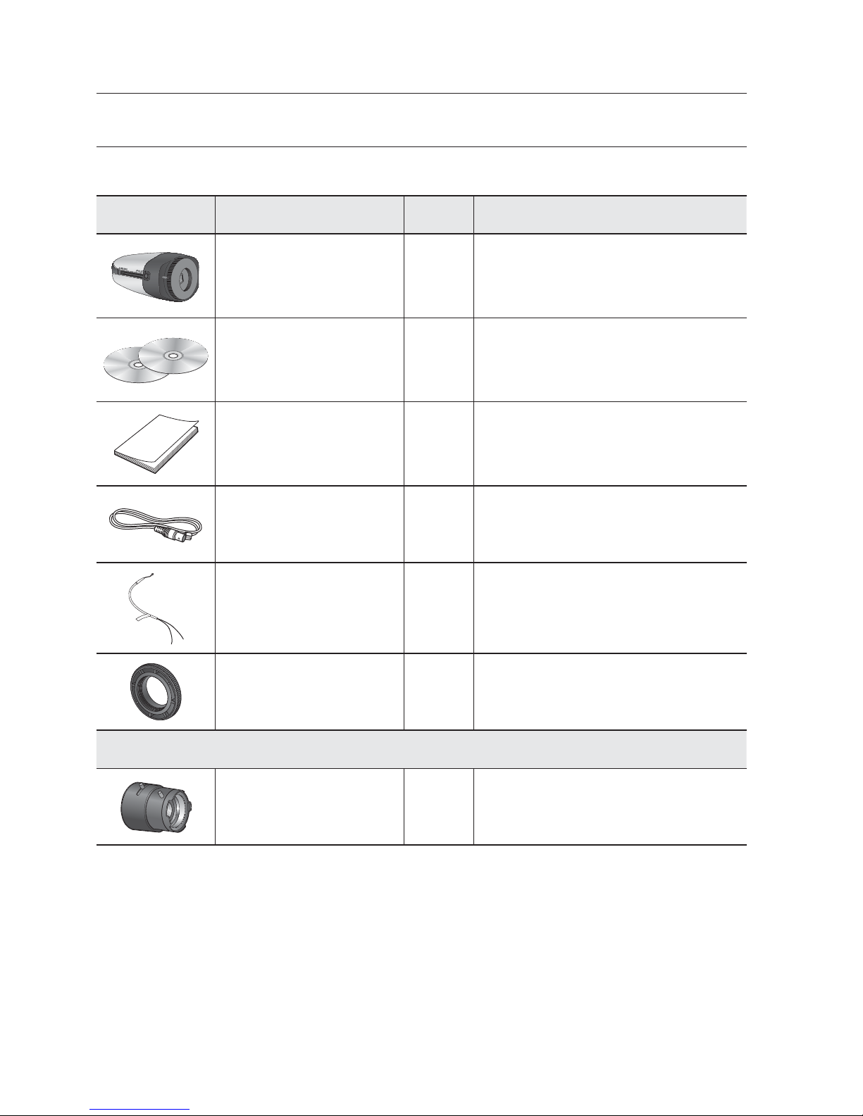
WHAT’S INCLUDED
Please check if your camera and accessories are all included in the product package.
Appearance Item Name Quantity Description
Camera 1
Instruction book,
Installer S/W CD,
CMS S/W DVD
2
Quick Guide (Optional) 1
Cable for the testing monitor 1
Used to test the camera connection to a
portable display device
Alarm Cable 1 Used to connect to Alarm input
C Mount Adapter 1 Used to install the C Mount camera lens
Lens Options (not included)
CS/C Lens Optional lens to be inserted in a camera
English _11
● OVERVIEW
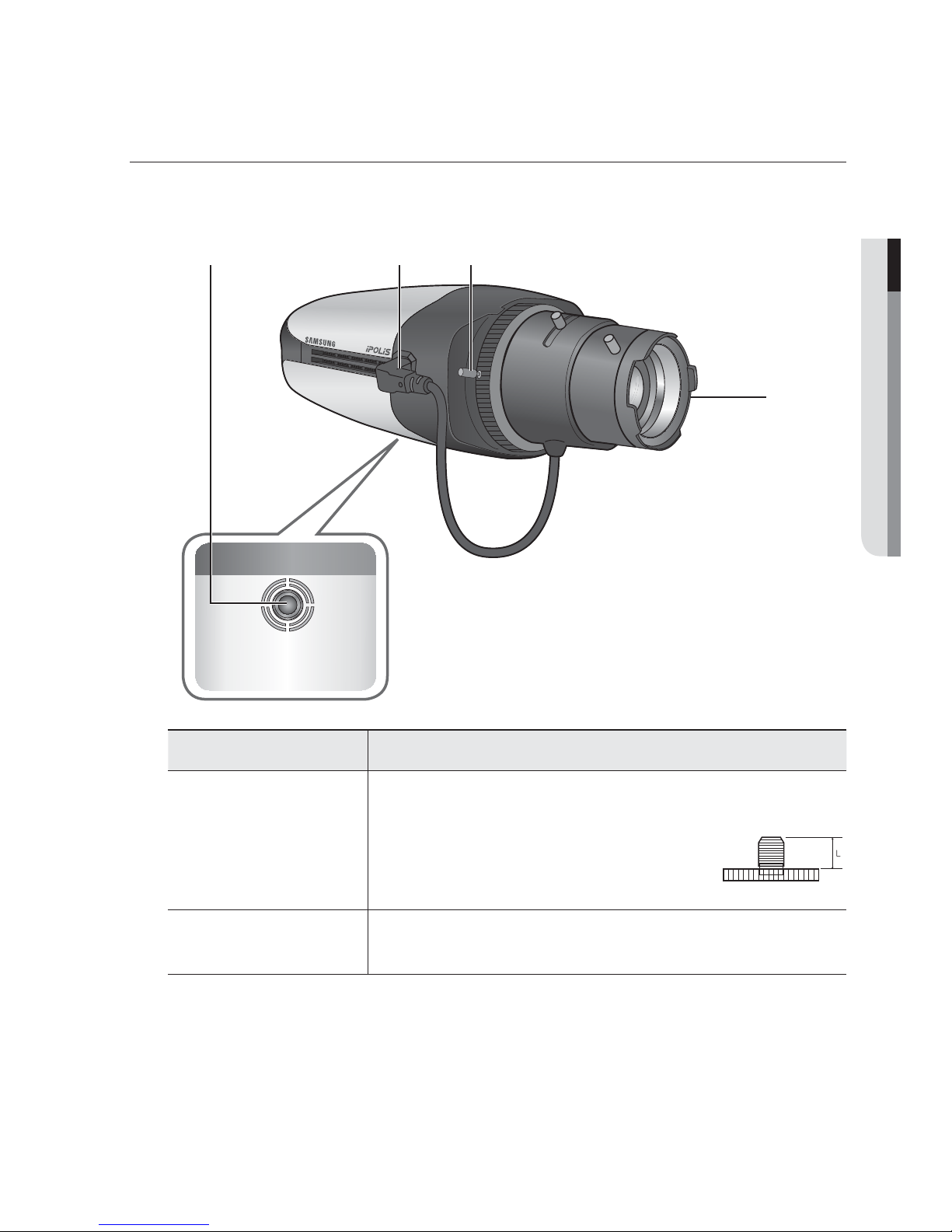
AT A GLANCE
Front Side
Item Description
Mounting Bracket
Screw Hole
Used to fix the camera on a mounting bracket.
The screw size : use this screw to fix the mounting bracket.
1/4" - 20UNC (20THREAD/1")
L : 4.5mm±0.2mm (ISO Standard), or 0.197"
(ASA Standard)
b
Auto Iris Lens
Connector
Used to supply power and output signal to control the iris of the lens.
b c

overview
12_ overview
Item Description
c
FBL Lever
Adjust the FBL (Flange-Back Length) value according to the lens.
Auto Iris Lens
(Optional)
Installed on the lens adaptor.
M
Wipe out a dirty surface of the lens softly with a lens tissue or cloth to which you have applied
ethanol.
Mounting Bracket is not included.
For more information to use mounting bracket, refer to the product’s documentation.
English _13
● OVERVIEW
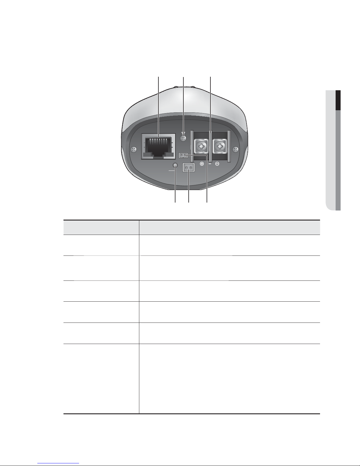
Rear Side
Item Description
Network Port Used to connect a PoE or LAN cable.
b
Lightning protective
grounding port
Used to discharge the lightning current safely outside in order to protect the
camera.
c
Power Port Used to plug the power cable.
Alarm Input Port Used to connect the alarm input signal.
Video Out Port Analog video output port. (for installation)
Reset Button
Resets the camera settings to the default.
Press and hold for about 5 seconds to reboot the system.
J If you reset the camera, the network settings will be adjusted so that
DHCP can be enabled. If there is no DHCP server in the network, you
must run the IP Installer program to change the basic network settings
such as IP address, Subnet mask, Gateway, etc., before you can
connect to the network.
VIDEO
ALARM
IN
ACT LINK
NETWORK
RESET
DC12V
b c

14_ installation & connection
MOUNTING THE LENS
Disconnect the power before proceeding.
M
The C lens and CS lens are not included in the product package.
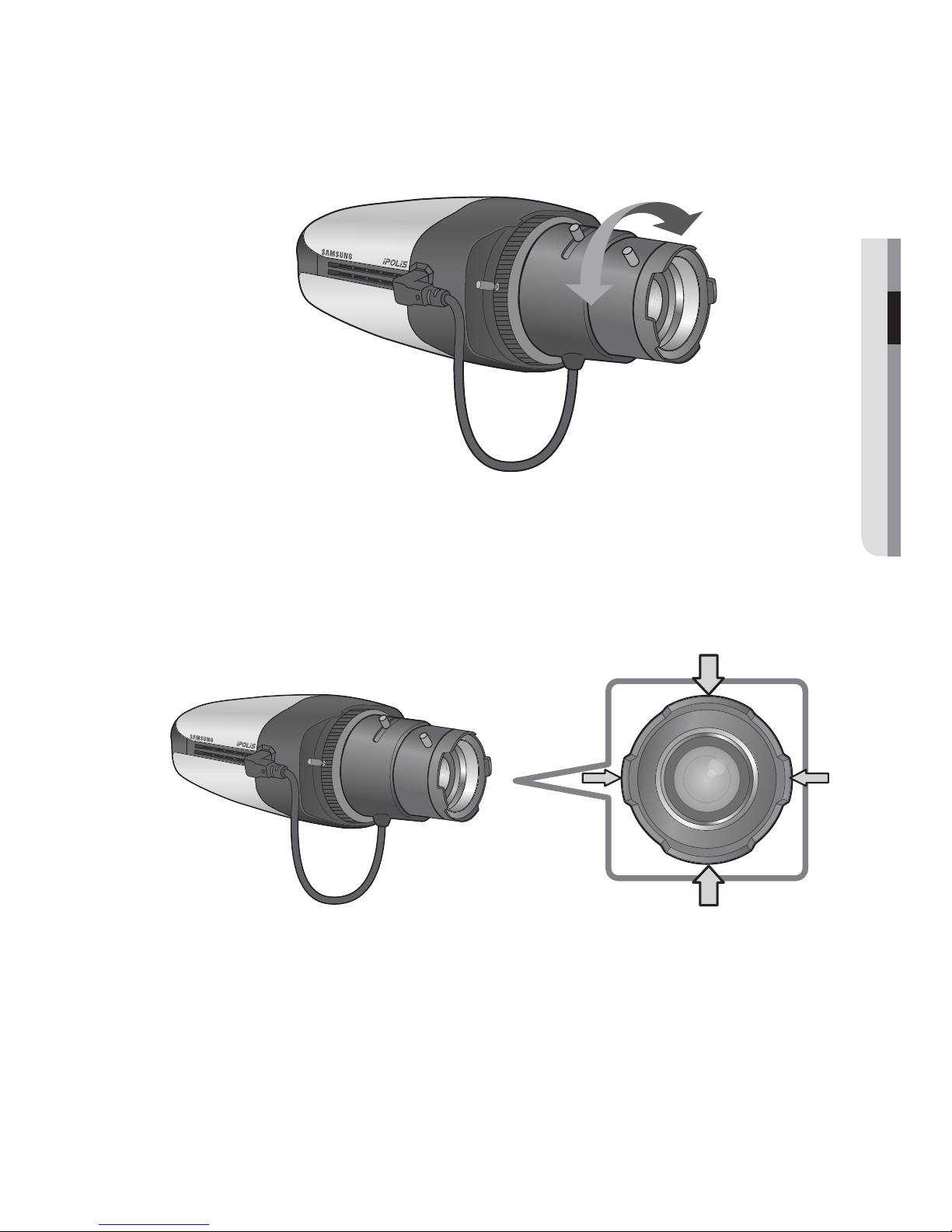
Mounting the lens onto the C/CS mount camera
1. Fit the lens into the mounting screw hole and turn it clockwise. Tighten the screw.
Then, it rotates in SLIP mode.
2. Turn it clockwise until it contacts on the stopper and stops.
3. As you can turn it counter clockwise from the stop point to rotate it in Slip mode,
adjust the angle to your preference within the range.
4. Connect the lens cable to the camera connector.
installation & connection
C/CS Lens
English _15
● INSTALLATION & CONNECTION
5. Use the focus lever and zoom lever to fit the zoom factor and focus. Then, fix the
lens with the camera.
Using a lens with hood
The round hood is mounted on the camera lens, which is designed to prevent flare/ghost/
light spreading. If it is installed improperly, it may cause shading on the screen.
Install the hood so that the wider side is placed vertically; and the narrower side is put
horizontally.
installation & connection
16_ installation & connection
CONNECTING WITH OTHER DEVICE
J
The BNC Out terminal of the product is provided for easier installation, and is not recommended
for monitoring purposes.
If you keep the BNC cable connected, a risk of lightening may cause damage or malfunction to
the product.
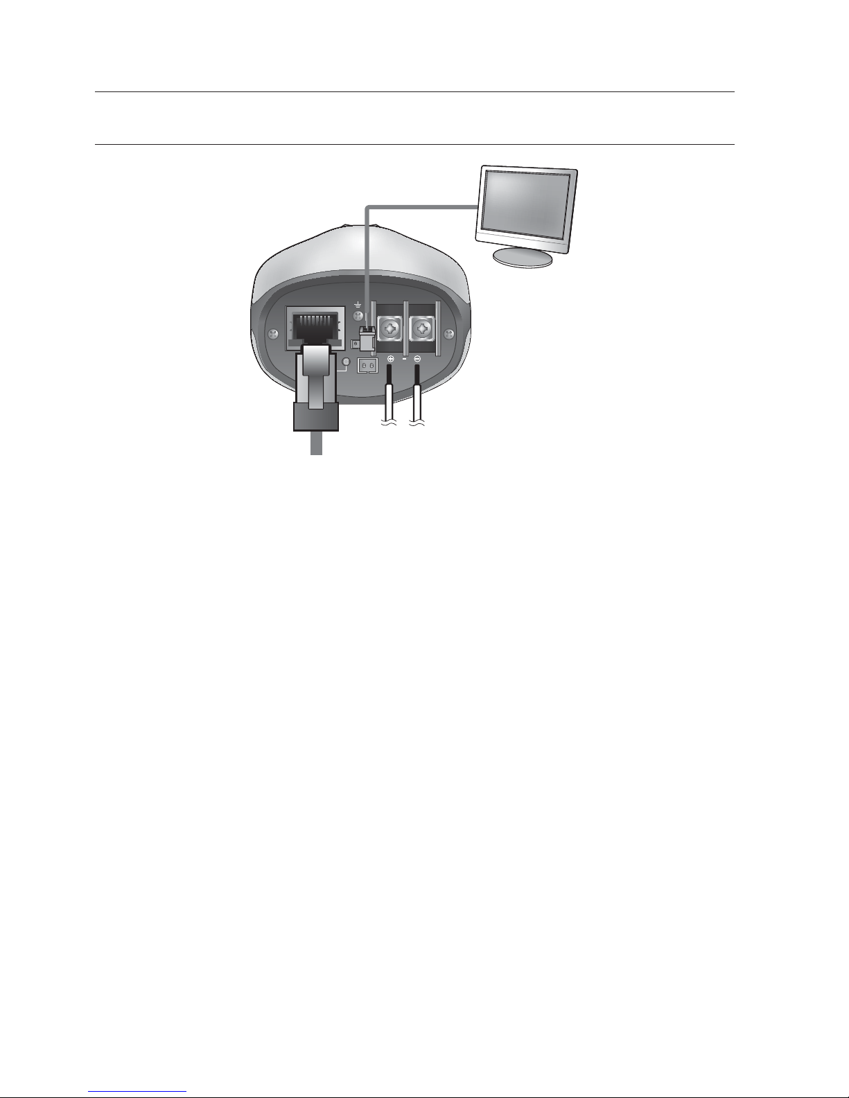
Ethernet Connection
Connect the Ethernet cable to the local network or to the Internet.
Power Supply
Use the screwdriver to connect each line (+, –) of the power cable to the corresponding
power port of the camera.
J
If both PoE and DC12V are applied simultaneously, the product will be supplied with power from
PoE.
-
You can also use a router featuring PoE (Power over Ethernet) to supply power to the camera.
-
Use PoE (Power over Ethernet) that is compliant with the IEEE802.3af protocols.
-
It is advisable to use only one power source from PoE and DC12V.
VIDEO
ALARM
IN
ACT LINK
NETWORK
DC12V
Monitor
(for installation)
Ethernet
Power
English _17
● INSTALLATION & CONNECTION
Be careful not to reverse the polarity when you connect the power cable.
-
Please connect the power adapter when the installation is completed.
-
As shown in the table below, you may encounter a voltage-sag depending on the wire length. If
you use an excessively long wire for camera connection, the camera may not work properly.
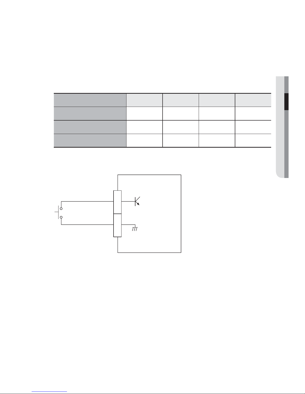
Electrical Resistance of Copper Wire at [20°C (68°F)]
Copper Wire Gauge (AWG) #24(0.22mm2) #22(0.33mm2) #20(0.52mm2) #18(0.83mm2)
Resistance (Ω/m) 0.078 0.050 0.030 0.018
Drop Voltage (V/m) 0.028 0.018 0.011 0.006
Recommended Distance (m) Less than 20 Less than 30 Less than 30 Less than 30
Alarm input Wiring Diagram
ALARM IN
GND
1
2
(5mA sink)
installation & connection
18_ installation & connection
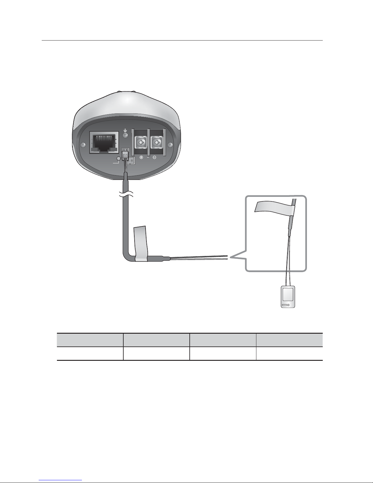
To connect to the alarm input port
Connect the alarm cable to the ALARM IN port in the rear panel.
Port Description Port Description
ALARM IN
Alarm Input Sensor Port
GND
GND port for the sensor
To connect the external sensor
Connect one strand of each signal line (2-strand) of the sensors to the [ALARM IN] port,
and connect the other strand to the [GND] port.
SENSOR
VIDEO
ALARM
IN
ACT LINK
NETWORK
DC12V
B
R
O
W
N
(
A
L
A
R
M
I
N
)
B
L
A
C
K
(
G
N
D
)
RESET
English _19
●
NETWORK CONNECTION AND SETUP
You can set up the network settings according to your network configurations.
CONNECTING THE CAMERA DIRECTLY TO LOCAL AREA
NETWORKING
Connecting to the camera from a local PC in the LAN
1. Launch an Internet browser on the local PC.
2. Enter the IP address of the camera in the address bar of the browser.
M
A remote PC in an external Internet out of the LAN network may not be able to connect to the
camera installed in the intranet if the port-forwarding is not properly set or a firewall is set.
In this case, to resolve the problem, contact your network administrator.
By factory default, the IP address will be assigned from the DHCP server automatically. If there is
no DHCP server available, the IP address will be set to 192.168.1.100.
To change the IP address, use the IP Installer.
For further details on IP Installer use, refer to “Static IP Setup”. (Page
24)
network connection and setup
<Local Network>
Camera
Camera
Local PC
INTERNET
Firewall
External Remote PC
DDNS Server
(Data Center, KOREA)
20_ network connection and setup
network connection and setup
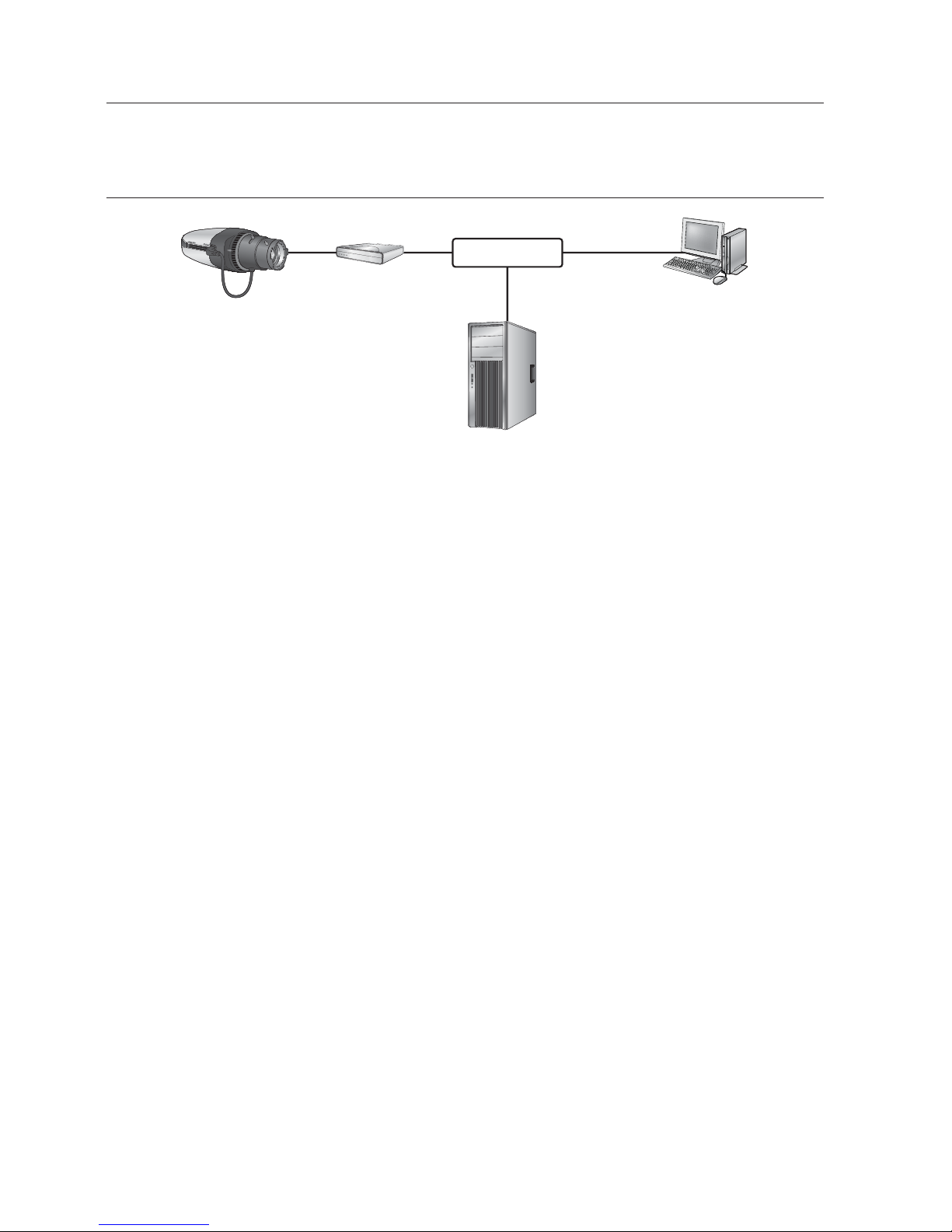
CONNECTING THE CAMERA DIRECTLY TO A DHCP
BASED DSL/CABLE MODEM
1. Use the cross LAN cable to connect the network cable directly to your PC.
2. Run the IP Installer and change the IP address of the camera so that you can use
the web browser on your desktop to connect to the Internet.
3. Use the Internet browser to connect to the camera.
4. Move to [Setup] page.
5. Move to [Network] – [DDNS] and configure the DDNS settings.
6. Move to [Network] – [Interface], and set the network type to [DHCP].
7. Connect the camera, which was removed from your PC, directly to the modem.
8. Restart the camera.
M
For registering the DDNS settings, refer to “Registering with DDNS”. (page 49)
For configuring the DDNS settings, refer to “DDNS”. (page 48)
For setting the network type, refer to “Interface”. (page 47)
Camera
External Remote PC
DDNS Server
(Data Center, KOREA)
DSL/Cable Modem
INTERNET
English _21
●
NETWORK CONNECTION AND SETUP
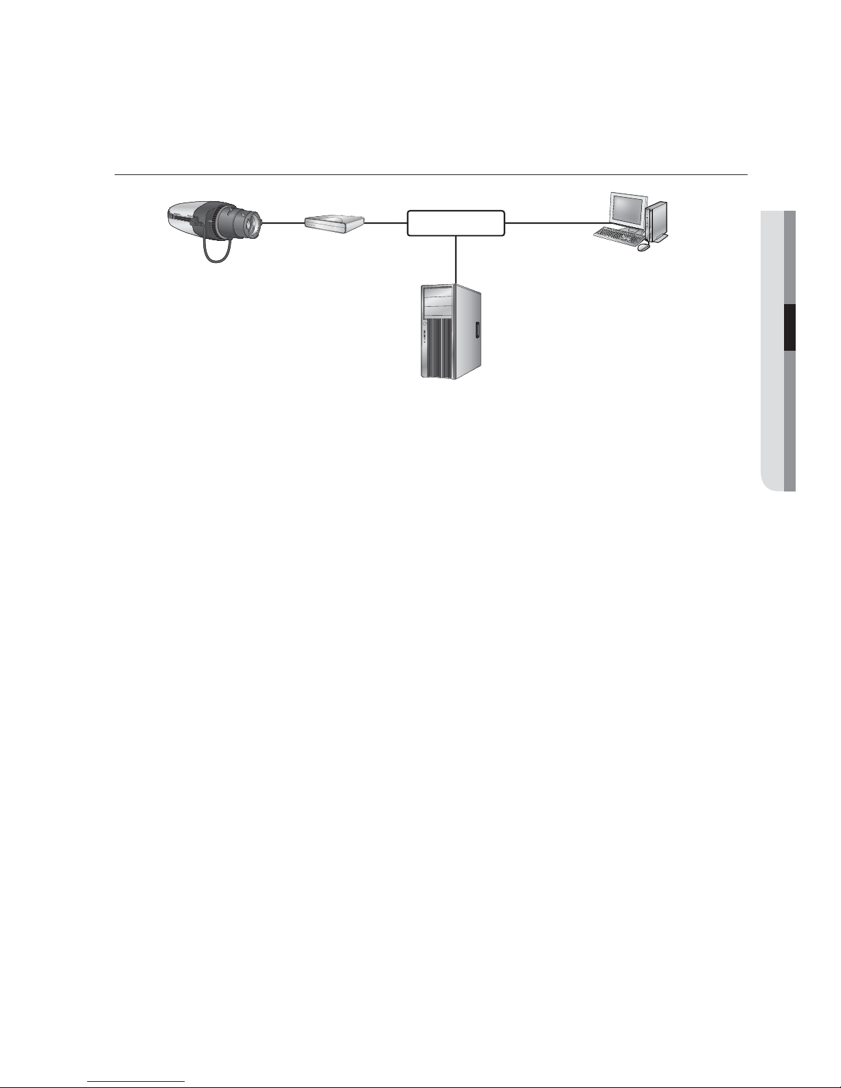
CONNECTING THE CAMERA DIRECTLY TO A PPPoE
MODEM
1. Use the cross LAN cable to connect the network cable directly to your PC.
2. Run the IP Installer and change the IP address of the camera so that you can use
the web browser on your desktop to connect to the Internet.
3. Use the Internet browser to connect to the camera.
4. Move to [Setup] page.
5. Move to [Network] – [DDNS] and configure the DDNS settings.
6. Move to [Network] – [Interface], and set the network type to [PPPoE].
7. Connect the camera, which was removed from your PC, directly to the modem.
8. Restart the camera.
M
For registering the DDNS settings, refer to “Registering with DDNS”. (page 49)
For configuring the DDNS settings, refer to “DDNS”. (page 48)
For setting the network type, refer to “Interface”. (page 47)
Camera
External Remote PC
DDNS Server
(Data Center, KOREA)
PPPoE Modem
INTERNET
22_ network connection and setup
network connection and setup
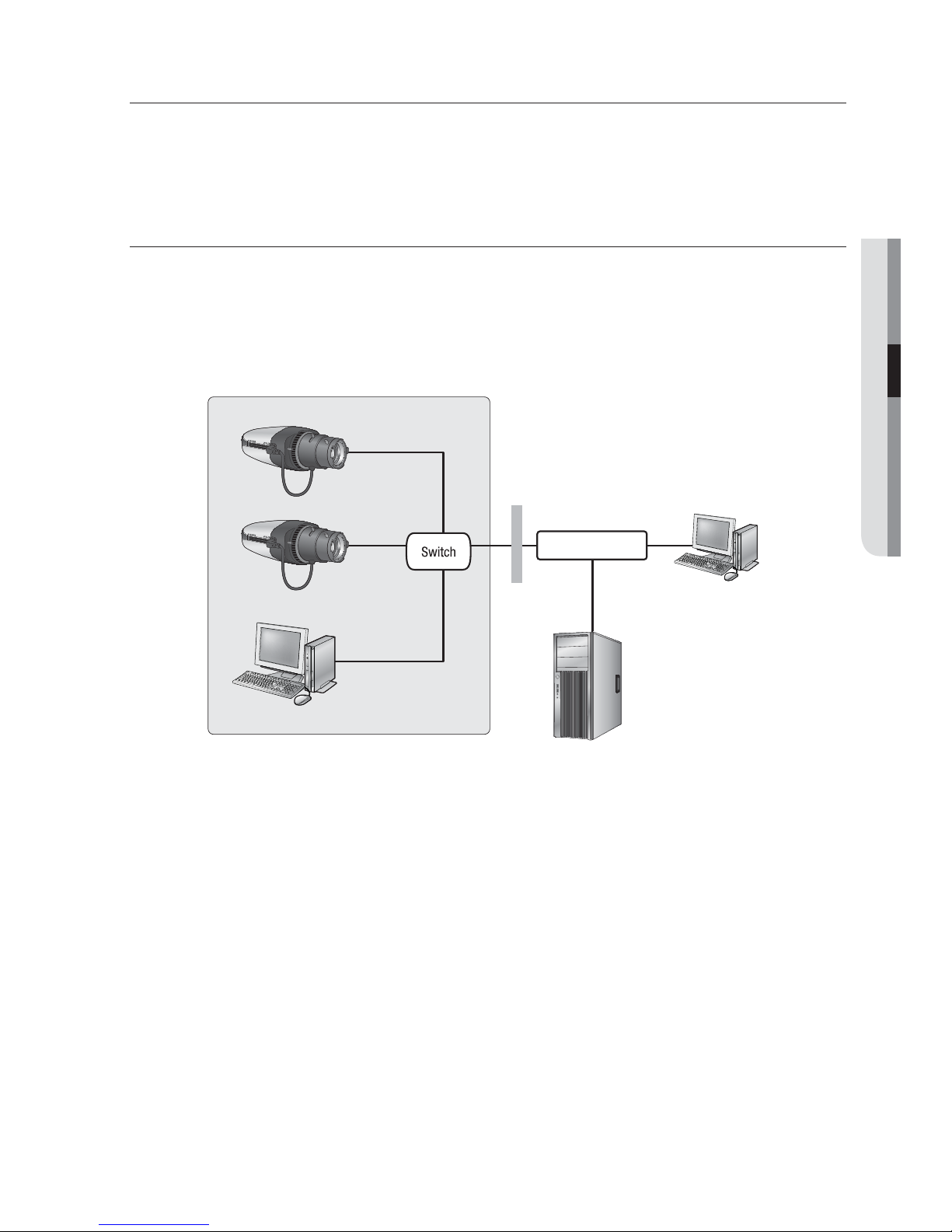
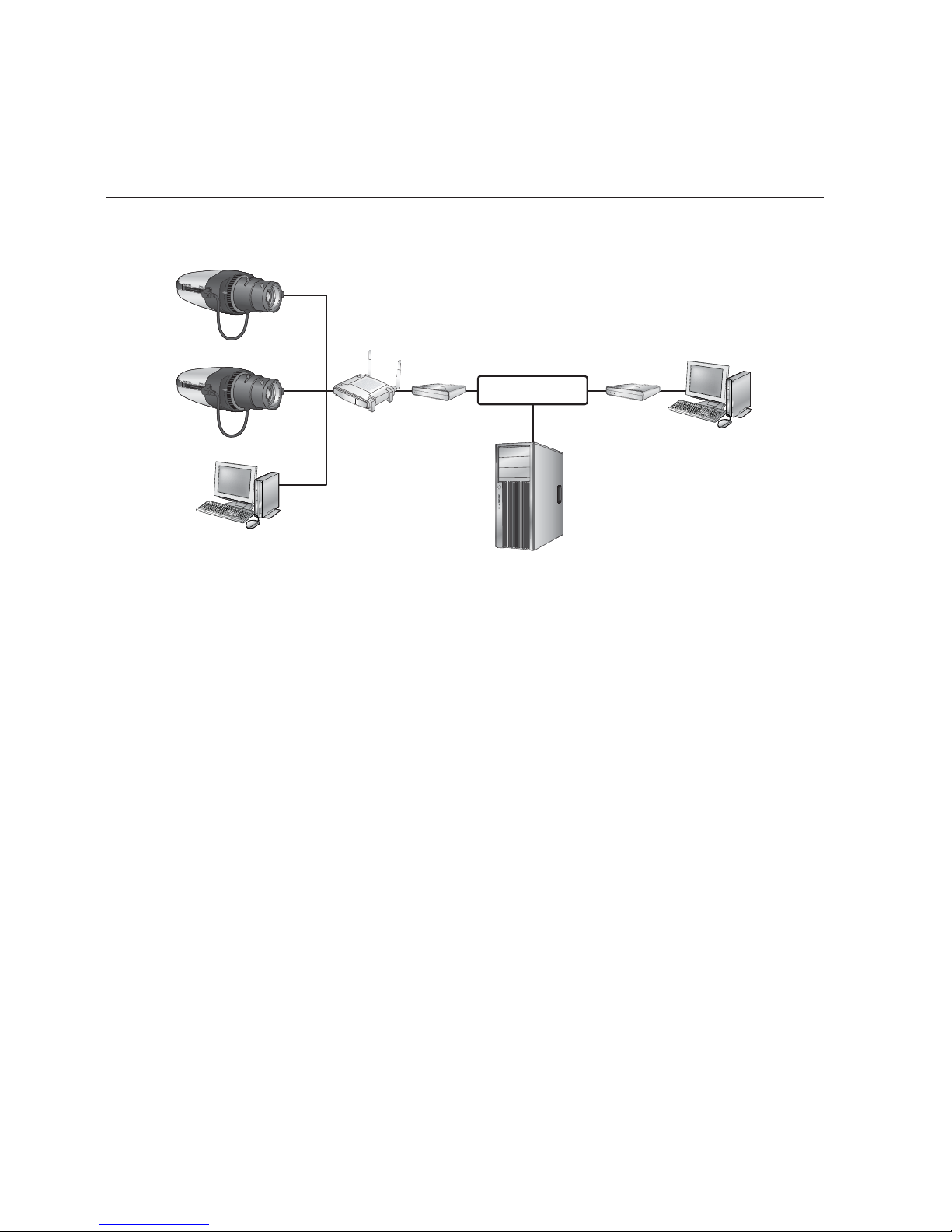
CONNECTING THE CAMERA TO A BROADBAND ROUTER
WITH THE PPPoE/CABLE MODEM
This is for a small network environment such as homes, SOHO and ordinary shops.
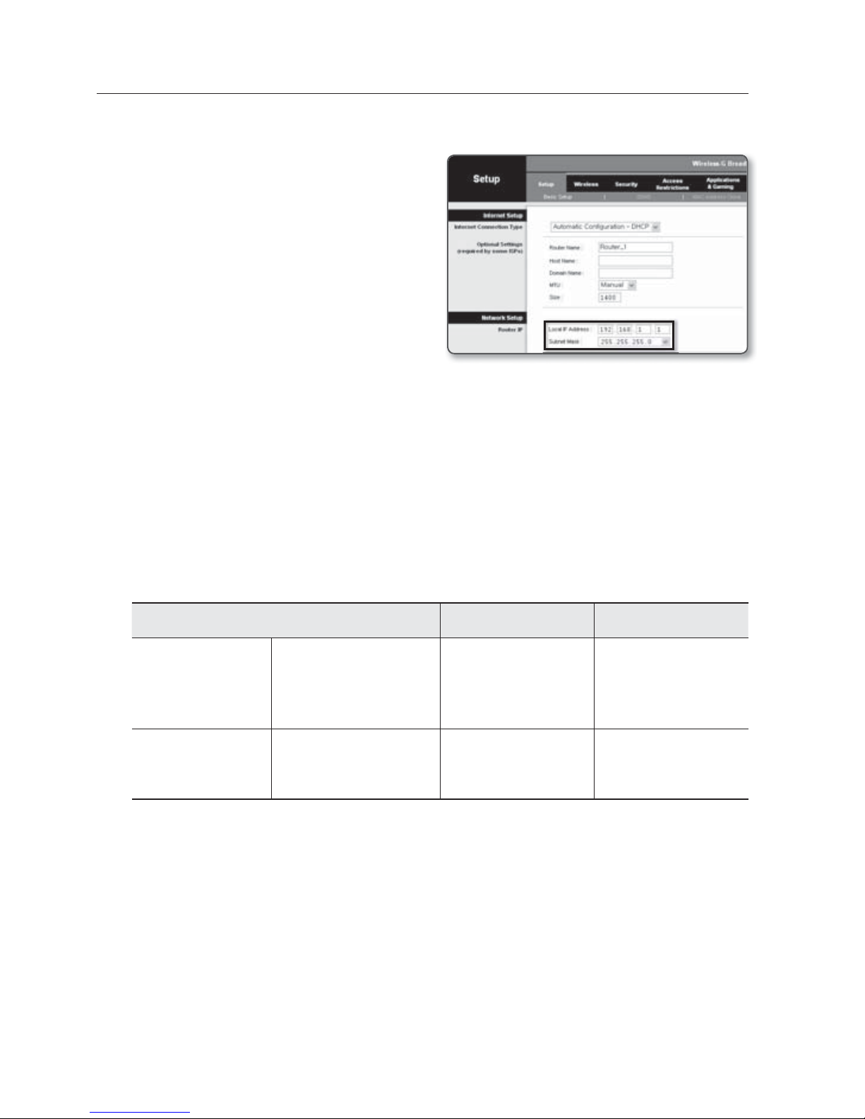
Configuring the network settings of the local PC connected to a
Broadband Router
Configuring the network settings of the local PC connected to a Broadband Router, follow
the instructions below.
• Select : <Network Neighborhood> <Properties> <Local Area Connection>
<Properties> <General> <Internet Protocol (TCP/IP)> <Properties>
<Obtain an IP address automatically> or <Use the following IP address>.
• Follow the instructions below if you select <Use the following IP address>:
ex1) If the address (LAN IP) of the Broadband Router is 192.168.1.1
IP address : 192.168.1.100
Subnet Mask : 255.255.255.0
Default Gateway : 192.168.1.1
ex2) If the address (LAN IP) of the Broadband Router is 192.168.0.1
IP address : 192.168.0.100
Subnet Mask : 255.255.255.0
Default Gateway : 192.168.0.1
ex3) If the address (LAN IP) of the Broadband Router is 192.168.xxx.1
IP address : 192.168.xxx.100
Subnet Mask : 255.255.255.0
Default Gateway : 192.168.xxx.1
M
For the address of the Broadband Router, refer to the product’s documentation.
Refer to the “Port Range Forward (Port Mapping) Setup” section of the Broadband Router’s
documentation. (Page
29)
Camera
Camera
Local PC
Broadband
Router
PPPoE or
Cable Modem
PPPoE or
Cable Modem
External Remote PC
DDNS Server
(Data Center, KOREA)
INTERNET
English _23
●
NETWORK CONNECTION AND SETUP
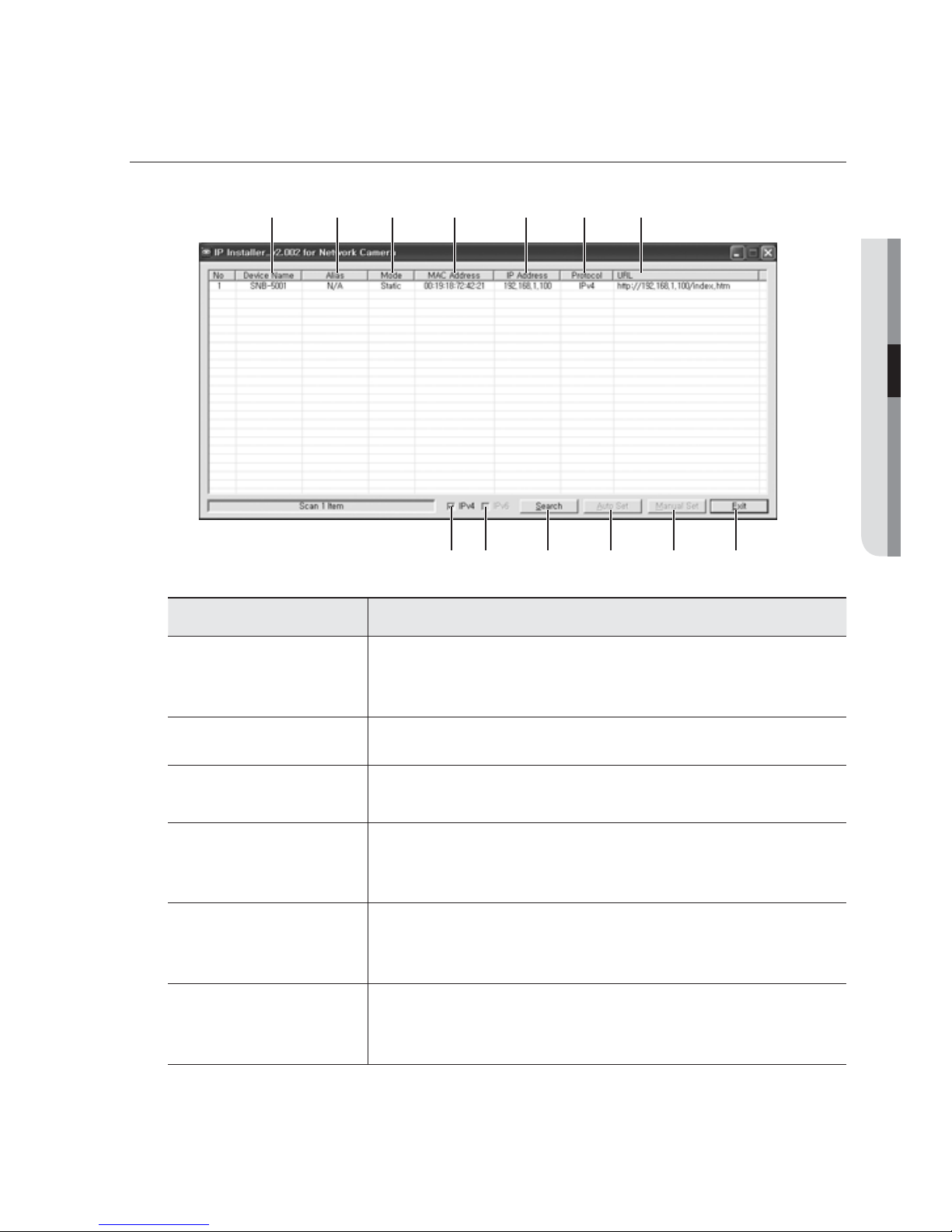
BUTTONS USED IN IP INSTALLER
Item Description
Device Name
Model name of the connected camera.
Click the column to sort the list by model name.
However, search will be stopped if clicked during the search.
b
Alias This function is not currently implemented.
c
Mode
Displays either
<Static>, <Dynamic> or <PPPoE> for the current network
connection status.
MAC(Ethernet)
Address
Ethernet address for the connected camera.
Click the column to sort the list by Ethernet address.
However, search will be stopped if clicked during the search.
IP Address
IP address.
Click the column to sort the list by IP address.
However, search will be stopped if clicked during the search.
Protocol
Network setting for the camera.
The factory default is “IPv4”.
Cameras with the IPv6 setting will be displayed “IPv6”.
b c
m
24_ network connection and setup
network connection and setup
Item Description
URL
DDNS URL address enabling access from the external Internet.
However, this will be replaced with the <IP Address> of the camera if
DDNS registration has failed.
IPv4 Scans for cameras with the IPv4 setting.
IPv6
Scans for cameras with the IPv6 setting.
Activated in an IPv6 compliant environment.
Search
Scans for cameras that are currently connected to the network.
However, this button will be grayed out if neither IPv4 nor IPv6 is checked.
Auto Set The IP Installer automatically configures the network settings.
Manual Set You should configure the network settings manually.
m
Exit Exits the IP Installer program.
M
For the IP installer, use only the installer version provided in the installation CD or use the latest one if
available. You can download the latest version from the Samsung web site (www.
samsungcctv.com).
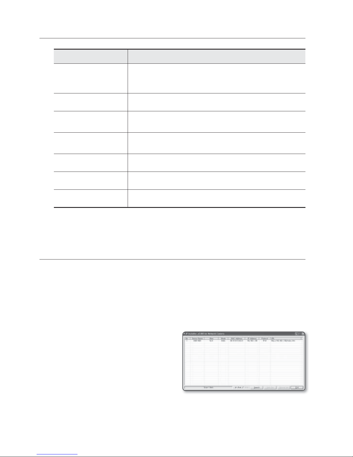
STATIC IP SETUP
Manual Network Setup
Run <IP Installer_vX.XX.exe> to display the camera search list.
At the initial startup, both [Auto Set] and [Manual Set] will be grayed out.
M
For cameras found with the IPv6 setting, these buttons will be grayed out as the cameras do not
support this function.
1. Select a camera in the search list.
Find the MAC (Ethernet) address
labeled on the rear of the camera.
Both the [Auto Set] and [Manual Set]
buttons will be activated.
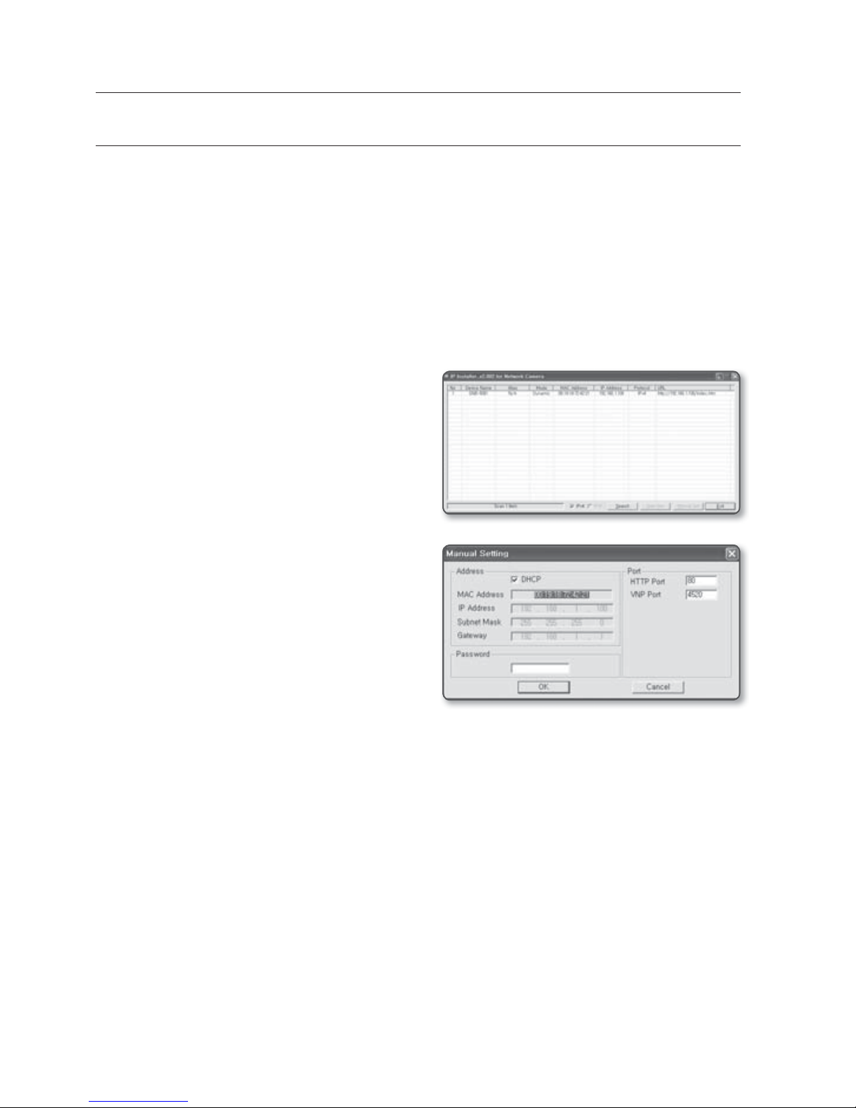
2. Click [Manual Set].
The Manual Setting dialog appears.
The default values of <IP Address>,
<Subnet Mask>, <Gateway>, <HTTP Port> and <VNP Port> of the camera will
be displayed.
English _25
●
NETWORK CONNECTION AND SETUP
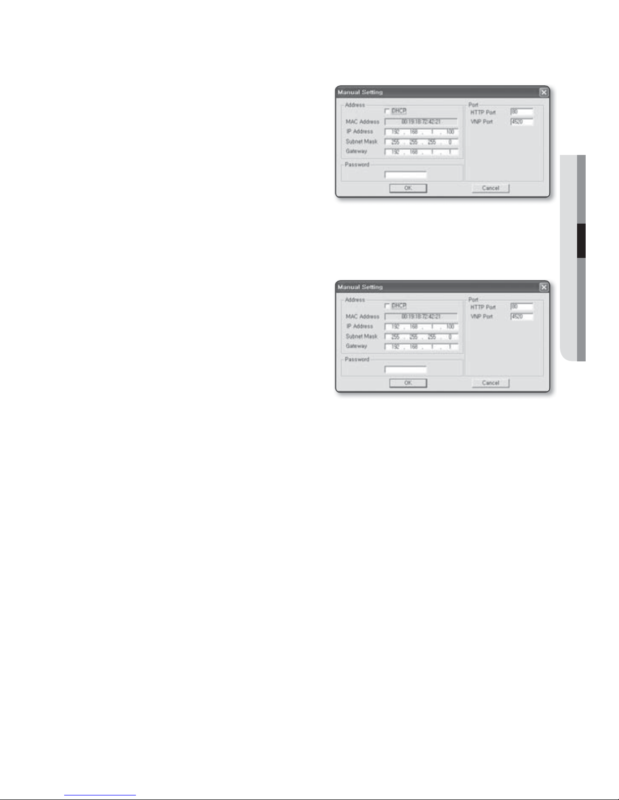
3. In the <Address> pane, provide the
necessary information.
• MAC (Ethernet) Address : The MAC
(Ethernet) address of the applicable
camera will be set automatically so
you don't need to input it manually.
M
You can configure the static IP settings
only if the DHCP checkbox is unchecked.
If not using a Broadband Router
For setting <IP Address>, <Subnet Mask>, and <Gateway>, contact your network administrator.
4. In the <Port> pane, provide necessary
information.
• HTTP Port : Used to access the
camera using the Internet browser,
defaulted to 80. Use the spin button
to change the HTTP Port value.
• VNP Port : Used to control the video
signal transfer, defaulted to 4520.
5. Enter the password.
This is the login password for the “admin” user who accesses the camera.
The default password is “4321”.
J
The default password can be exposed to a hacking thread so it is recommended to change the
password after installing the product.
Note that the security and other related issues caused by the unchanged password shall be
responsible for the user.
If you want to change the password, refer to “Administrator Password Change” of the user
setup. (page 63)
6. Click [OK].
Manual network setup will be completed.
26_ network connection and setup
network connection and setup
If using a Broadband Router
• IP Address : Enter an address falling in
the IP range provided by the Broadband
Router.
ex) 192.168.1.2~254,
192.168.0.2~254,
192.168.XXX.2~254
• Subnet Mask : The <Subnet Mask>
of the Broadband Router will be the
<Subnet Mask> of the camera.
• Gateway : The <Local IP Address> of
the Broadband Router will be the <Gateway> of the camera.
M
The settings may differ depending on the connected Broadband Router model.
For more information, refer to the user manual of the applicable router.
Refer to the “Port Range Forward (Port Mapping) Setup” section of the Broadband Router’s
documentation. (Page
29)
If the Broadband Router has more than one camera connected
Configure the IP related settings and the Port related settings distinctly with each other.
ex)
Category Camera #1 Camera #2
IP related settings
IP Address
Subnet Mask
Gateway
192.168.1.100
255.255.255.0
192.168.1.1
192.168.1.101
255.255.255.0
192.168.1.1
Port related settings
HTTP Port
VNP Port
8080
4520
8081
4521
M
If the <HTTP Port> is set other than 80, you must provide the <Port> number in the address bar
of the Internet browser before you can access the camera.
ex) http://IP address : HTTP Port
http://192.168.1.100:8080
English _27
●
NETWORK CONNECTION AND SETUP
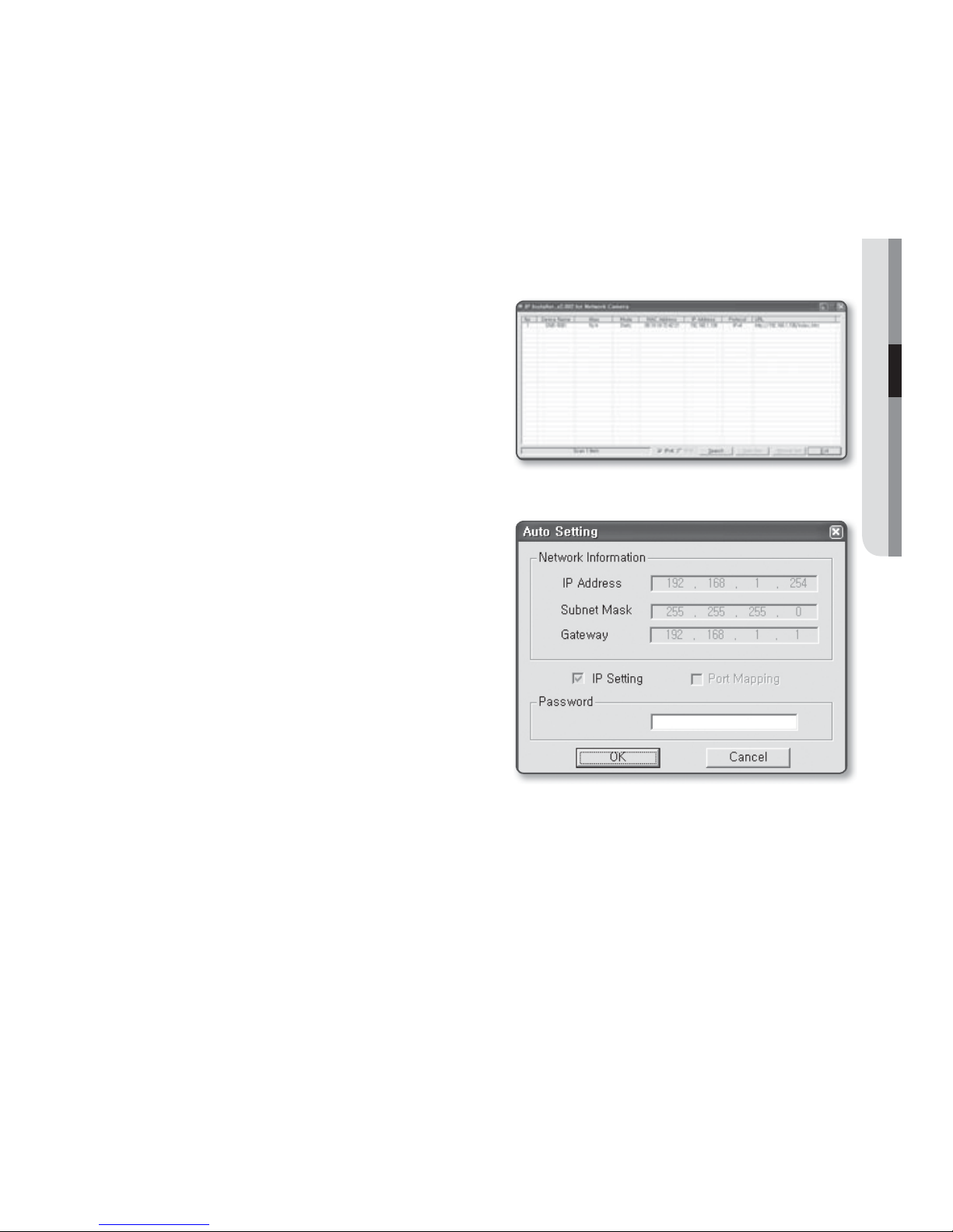
Auto Network Setup
Run <IP Installer_vX.XX.exe> to display the camera search list.
At the initial startup, both [Auto Set] and [Manual Set] will be grayed out.
M
For cameras found with the IPv6 setting, these buttons will be grayed out as the cameras do not
support this function.
1. Select a camera in the search list.
Find the MAC (Ethernet) address
labeled on the rear of the camera.
Both the [Auto Set] and [Manual Set]
buttons will be activated.
2. Click [Auto Set].
The Auto Setting dialog appears.
The <IP Address>, <Subnet Mask>,
and <Gateway> will be set automatically.
3. Enter the password.
This is the login password for the
“admin” user who accesses the camera.
The default password is “4321”.
The default password can be exposed to
a hacking thread so it is recommended to
change the password after installing the
product.
Note that the security and other related issues
caused by the unchanged password shall be
responsible for the user.
If you want to change the password, refer to
“Administrator Password Change” of the user setup. (page 63)
4. Click [OK].
Auto network setup will be completed.
28_ network connection and setup
network connection and setup
DYNAMIC IP SETUP
Dynamic IP Environment Setup
• Example of the Dynamic IP environment
- If a Broadband Router, with cameras connected, is assigned an IP address by the
DHCP server
- If connecting the camera directly to modem using the DHCP protocols
- If IPs are assigned by the internal DHCP server via the LAN
Checking the Dynamic IP
1. Run the IP Installer on the user’s local
machine to display cameras allocated
with <Dynamic IP> addresses in the
list.
2. Select a camera in the list, and click
[Manual Set] to check the <Dynamic
IP> of the camera.
If you uncheck <DHCP>, you can
change IP to <Static>.
 Loading...